
VDV 457 eng
150
gmm VDV Recommendation 457 4/2018 Automatic Passenger Counting Systems (APCS) Recommendations for the Application of APCSs within Public Transport and Regional Rail Transport, Version 2.1
Transcript of VDV 457 eng
gmm
VDV Recommendation 4574/2018
Automatic Passenger Counting Systems (APCS)
Recommendations for the Application of APCSs within Public Transport and Regional Rail Transport, Version 2.1

The English translation of VDV Recommendation 457 was supported by VDV Industrieforum e.V. and the following companies:
VDV Recommendation 457 | 4/2018 | 3
VDV Recommendation 457 04/2018
Automatic Passenger Counting Systems (APCS)
Recommendations for the Application of APCSs within Public Transport and Regional Rail Transport, Version 2.1
Overall revision of version 2.0 “Automatic passenger counting systems” working group (chairman: Dr. Rudolf Stagl, MVV, Munich) The VDV Committee on Information Processing and the VDV Subcommittee on Statistics were in charge of the working group. Preparation of version 2.1
XML interfaces
List of authors Dr. Silvia Köhler, BVG, Berlin Stephan Bobinger, MVG, Munich Ronny Branick, DB Vertrieb GmbH, Berlin Bernd‐Michael Cerfontaine, VVS, Stuttgart Sven Krogull, MDV, Leipzig Andreas Luther, DB Vertrieb GmbH, Berlin Dr. Manfred Ritschel, TCAC, Dresden Michael Schulze, MVV, Munich Manfred Starck, HVV, Hamburg Winfried Bruns, VDV, Cologne Dr. Manfred Ritschel, TCAC, Dresden Dr. Silvia Köhler, BVG, Berlin Ronny Branick, DB Vertrieb GmbH, Berlin Prof. Brunner, University of Göttingen David Ellenberger, University of Göttingen Andreas Luther, DB Vertrieb GmbH, Berlin Michael Siebert, Interautomation, Berlin Winfried Bruns, VDV, Cologne Baumann, Berlin Bracher, DResearch, Berlin Branick, Berlin Cerfontaine, VVS, Stuttgart Ebeling, SIGNON, Hamburg Foerster, HVV, Hamburg Friebel, Connective GmbH, Hüttwilen Grettenberger, Iris, Berlin Hagemann, Hanover Herold, COSMO CONSULT BI GmbH, Munich Keppeler, GVS, Hanover Kluge, Berlin Köhler, BVG, Berlin

VDV Recommendation 457 | 4/2018 | 4
Langenhan, Berlin Löhner, WVI, Brunswick Oltrogge, WVI, Brunswick Rebske, Bad Nenndorf Schmidt, UVT GmbH, Mainz Schubert, IRIS, Berlin Schüßler, DResearch, Berlin Sonderegger, Neuhausen am Rheinfall Tröller, Neuhausen am Rheinfall Vogel, PTV, Karlsruhe Winfried Bruns, VDV, Cologne
© The user is responsible for the correct and careful application of the Recommendation. If the user observes a potential danger or
irregularities in connection with the application of this Recommendation, he is requested to inform the VDV directly. Any liability of the VDV
and persons involved in the preparation of this Recommendation is excluded to the maximum extent permitted by law.
© Verband Deutscher Verkehrsunternehmen e. V. Cologne 2018 | All rights reserved, including the rights of the reprint of excerpts, the
photomechanical reproduction, the duplication and distribution via special processes (e.g. data processing) and the translation.
VDV Recommendation 457 | 4/2018 | 5
Preface
To be able to realise decision, control and verification processes, reliable statistical data are needed. Thus, e.g. data on variables, structures and the distribution of the demand for transport over the day are essential within public transport and regional rail transport to realise demand‐oriented, revenue‐sharing processes. Moreover, reliable statistical data are needed as verification parameters for the financing of the transport performance in accordance with Regulation (EC) No 1370/2007 as well as for the planning of transport services and calls for tenders. Therefore, transport companies, competent authorities and transport associations increasingly require and evaluate demand‐oriented data.
Not only the quality of the statistical data and the degree of aggregation of the transport demand data, but also the effort and cost for the collection and update of these data are important. Distinction is made between a traffic census with a public opinion poll and a traffic census exclusively based on automatic passenger counting systems (APCS). A traffic census with a public opinion poll provides thorough information about the passengers’ behaviour (starting point and destination of journeys, kinds of ticket used etc.), but is very expensive and time‐consuming. Therefore, it is usually only made every 3 – 5 years.
A traffic census exclusively based on automatic passenger counting systems provides less data, i.e. only the transport volume parameter (number of passengers transported per line) and the transport performance parameter (km) within the considered period, by detecting or calculating the number of persons boarding and alighting a vehicle at each stop and the occupation between any two stops, but it is much more inexpensive. Moreover, automatic passenger counting systems can be used together with public opinion polls on the transport behaviour and to update traffic flow data. Therefore, many urban and regional transport companies equip their buses and/or rail vehicles with such systems.
It is especially important that the results of the counting and the extrapolation that concern several kinds of vehicles and are made by several transport companies can be exactly compared with one another. This requirement is essential if the data are to be used e.g. as a calculation basis for the revenue sharing within a transport association or for compensation payments. Therefore, it is absolutely essential that uniform system solutions are available for public transport and regional rail transport. The revised VDV Recommendation 457 is to fulfil this requirement.
It always has to be born in mind that terms specific to one mode of transport are used in a generic sense. Thus, e.g. “station load” also means “stop load”.
All requirements, recommendations and general advice concerning automatic passenger counting systems are explained in detail in this revised VDV Recommendation in the following chapters:
— 1 Scope of application and functional requirements;
— 2 Statistical requirements for the APCS;
— 3 Count journey planning elements;
— 4 Sample size and level of equipment needed;
— 5 Availability of count journeys in the timetable/cycle;
— 6 Check and correction of the quality of count journeys;

VDV Recommendation 457 | 4/2018 | 6
— 7 Requirements for the counting accuracy;
— 8 Correction and balancing procedure;
— 9 Possible standard solutions for special operating/technical cases;
— 10 Plausibility checks and corrections;
— 11 Extrapolation.
Specific advice, information on specific subject matters and specific requirements are given in:
— Annex A: Check list for the quality management concerning the operation of the APCS;
— Annex B: Rules for verifying and certifying the counting accuracy;
Annex C: Rules for accepting a background system;
— Annex D: Framework specification;
— Annex E: Interface specification;
from the point of view of the users for application in real projects.
As regards the practical application attention is drawn to the following:
a) VDV Recommendation 457, inclusive of its annexes, is a consistent, complete document. Its advice, recommendations and rules can only be applied within this textual and methodical context. It is regarded as non‐expedient only to implement one solution or some partial solutions.
b) The concrete use case and the existing technical, economic and organisational conditions of the transport company in question shall always be described. This applies particularly to the preparation of specifications. The framework specification in this VDV Recommendation is for general orientation purposes only and cannot replace a thorough analysis of the actual conditions and the objectives of the application of an APCS in a transport company. The transport company shall specify the specific requirements in its call for tenders on the basis of the given possibilities and the actual conditions.
c) When it is being planned to introduce an APCS, it always has to be borne in mind that it is a complex process, which includes both technical and organisational processes. Therefore, it has to be examined which know‐how the transport company has itself, which additional personnel is needed and how the APCS can be integrated into the planning and operational structure of the company. Annex A comprises a check list with the quality management processes that have to be considered at the planning stage and that can be realised during the operation.
d) The planning of the introduction of an APCS is very complex, very important and very time‐consuming. Experience gained from numerous reference projects has taught us that at least one year is needed for the following typical stages of work:
— determination of the functional and statistical requirements;
— preparation of company‐specific requirements specifications;
— call for tenders/award;
— final preparation of company‐specific performance specifications (detailed specification);
— installation of the single systems;
— system integration tests;
VDV Recommendation 457 | 4/2018 | 7
— comparative counting to certify the counting accuracy;
— system acceptance;
— reference applications.
If the general conditions are observed, individual, innovative system solutions can be realised. The single system components of the various manufacturers can be so designed that they are compatible to one another or can be integrated into existing systems.
In this way each transport company is able to realise its optimal solution by way of components from several manufacturers.
Supplement to the preface of this edition (version 2.1)
The present version 2.1 of VDV Recommendation 457 includes requirements for the counting accuracy (chapter 7) as well as supplements and modifications concerning the verification of the statistical non‐distortion of APCSs (Annex B, B.1 and B.2).
Already in version 2.0 of VDV Recommendation 457 it was pointed out in 13.2.3 that it was the intention to update it when sensors with greater counting accuracy and less spread of the count values had been developed. Therefore, the working group subjected to counting accuracy has dealt with the verification of the statistical non‐distortion together with representatives from industry and science on behalf of the VDV Subcommittee on Statistics. The result is concrete, verified proposals for the verification of the statistical non‐distortion on the basis of empirical data from practical applications. These data include the qualification of the sample planning in consideration of the users and manufacturers’ risks, i.e. that statistically distorted APCSs are approved or – vice versa – that statistically non‐distorted APCSs are not approved (B.1). Moreover, the t‐test procedure described in version 2.0 has been replaced by the more transparent equivalence test procedure to ensure that an APCS can only be certified if it has been proved in the manual comparative counting that its deviations in counting accuracy do not exceed a statistical limit defined already at the sample planning stage of the comparative counting. This new procedure, inclusive of an exemplary calculation, is described in B.2.
The procedure for verification of the statistical non‐distortion on the basis of the equivalence test and the modified sample planning in consideration of faults of the 1st kind and the 2nd kind should be applied to all public calls for tenders for automatic passenger counting systems published as from 30.06.2019. It is not recommended to apply it to existing systems or to systems for which the calls for tenders have been made already or to systems that are being procured.
If you have any comments to these modifications, you are welcome inform to the VDV Subcommittee on Statistics and its “counting accuracy” working group.
VDV Recommendation 457 | 4/2018 | 8
Table of Contents
Preface 5
Table of Contents 8
Abbreviations / Terms and Definitions 12
1 Scope of Application and Functional Requirements 14
2 Statistical Requirements for the APCS 17
2.1 Overview 17
2.2 Statistical Quality of APCS Data 17
3 Count Journey Planning Elements 20
3.1 Count Journey Planning in Case of Planned Availability 20
3.1.1 Assignment Criteria 20
3.1.2 Count Journey Planning 20
3.2 Count Journey Planning in Case of Random Availability 22
3.2.1 Assignment Criteria 22
3.2.2 Count Journey Planning 22
4 Sample Size and Level of Equipment Needed 24
4.1 Sample Size and Level of Equipment Needed in Case of Planned Availability 24
4.1.1 Determination of the Sample Size 24
4.1.2 Determination of the Level of Equipment Needed in the Vehicles 25
4.2 Sample Size and Equipment Needed in Case of Random Availability 26
4.2.1 Equipment Strategy 26
4.2.2 Determination of the Level of Equipment Needed in the Vehicles 27
5 Availability of Count Journeys in the Timetable/Cycle 31
5.1 Plannable Availability of Count Journeys 31
5.2 Random Availability of Count Journeys 31
6 Check and Correction of the Quality of Count Journeys 32
6.1 Check and Correction in Case of Planned Availability 32
6.2 Check and Correction in Case of Random Availability 33
7 Requirements for the Counting Accuracy 35
VDV Recommendation 457 | 4/2018 | 9
8 Correction and Balancing Procedure 36
8.1 Balance Settlement 36
8.2 Waiting Room Effect 37
9 Possible Standard Solutions for Special Operating/ Technical Cases 38
9.1 Cases Specific to Public Transport 38
9.2 Cases Specific to Regional Rail Transport 38
9.2.1 Production Form 38
9.2.2 Offer Concepts 40
9.2.3 Vehicle Concept 40
9.2.4 Distinction after Coach Classes 42
9.2.5 Different Degrees of Occupation in the Same Coach Class 42
9.2.6 Monitoring of the Process Chain 43
10 Plausibility Checks and Corrections 44
11 Extrapolation 45
11.1 Stratum‐bound Extrapolation from Sample 45
11.2 Extrapolation on the Basis of the Performance Block Procedure 45
11.3 Extrapolation on the Basis of the Vehicle Concept 47
Annex A: Check List for the Quality Management concerning the Operation of the APCS 48
Annex B: Rules for Verifying and Certifying the Counting Accuracy 58
B.1 Manual Comparative Counting 58
B.1.1 Sample Planning 58
B.1.2 Explanations and Recommendations concerning the Parameters to be Selected 58
B.1.3 Example of Sample Planning 59
B.2 Counting Accuracy 60
B.2.1 Verification Level, Parameters and Requirements 60
B.2.2 Determination of Counting Errors 62
B.3 End of the Revision of Comparative Counting for Certifying the Counting Accuracy 66
B.3.1 General Requirements 66
B.3.2 Manual Comparative Counting for Certifying the Counting Accuracy 67
B.3.3 Comparative Counting by way of (Video) Image Recording 73
Annex C: Rules for Accepting a Background System 79
C.1 Objective 79
C.2 System Acceptance Scenarios 80
C.2.1 Test Contents 80
VDV Recommendation 457 | 4/2018 | 10
C.2.2 Description 81
C.3 Re‐certification of the Counting Accuracy via Data from the Background System 86
C.3.1 Task 86
C.3.2 Mathematical‐statistical Approaches 86
C.3.3 Re‐certification 87
Annex D: Framework Specification 89
D.1 Preliminary Remarks about the Framework Specification 89
D.2 Vehicle Equipment – On‐board Systems 90
D.2.1 Fundamentals, Context and Requirements 90
D.2.2 Sensors or Detection Systems 91
D.2.3 Signals Needed 93
D.2.4 Central APC Components in the Vehicle 94
D.2.5 On‐board Interfaces 97
D.2.6 Tracking 97
D.2.7 Data Collection 99
D.2.8 Data Management 101
D.2.9 Data Supply and Data Transfer 103
D.2.10 Installation Planning, Cabling and Mounting in the Vehicle 104
D.2.11 Fitting Conditions 104
D.2.12 Organisational Requirements 108
D.3 Background System 109
D.3.1 Basic Requirements 109
D.3.2 System Architecture and System Environment 111
D.3.3 Interfaces, Consistency and Logging 112
D.3.4 Functionality 114
D.3.5 Documentation 126
D.4 Data Integration 127
D.4.1 VDV Recommendations and VDV Reports 127
D.4.2 Timetable and Network Data (VDV Recommendation 452) 129
D.4.3 Data Communication in the Vehicle (Generation, Storage and Check of Data – VDV 457‐1 Interface) 129
D.4.4 Transfer of Data from the APC‐OBU to a Control Centre/Radio Station (VDV 457‐2 Interface) 130
D.4.5 Interfaces in the Background System (VDV 457‐3 Interface) 131
D.4.6 Actual Vehicle Operating Data Interface (VDV 457‐4 Interface) 132
D.4.7 Vehicle Availability Data Interface (VDV 457‐5 Interface) 132
D.4.8 Further Possible Interfaces 132
D.4.9 Data Management and Administration 132
D.4.10 Transfer of Legacy Data 132
D.4.11 Formats 133
VDV Recommendation 457 | 4/2018 | 11
D.4.12 Special Radio Data Transmission Features 133
Annex E: Interface Specification 134
E.1 Interface between On‐board Unit and Sensors/Door Unit ‐ VDV 457‐1 Interface 134
E.1.1 Examples of Queries and Replies 135
E.2 Raw Data Interface ‐ VDV 457‐2 Interface 136
E.2.1 WayPointsMessage, OperationErrorMessage and PassengerCountingMessage 136
E.2.2 CountingArea and Counting 137
E.3 Count Data Interface ‐ VDV 457‐3 Interface 139
E.3.1 OperationErrorMessage and PassengerCountingServiceJourney 139
E.3.2 PassengerCountingMessage 140
E.3.3 CountingArea 141
E.4 Actual Vehicle Operating Data ‐ VDV 457‐4 Interface 146
E.5 Vehicle Availability Data Interface ‐ VDV 457‐5 Interface 147
List of Figures 148
Imprint 149
Translator’s note:
In case of doubt or differences to the German version of this Recommendation the German version is valid.
VDV Recommendation 457 | 4/2018 | 12
Abbreviations / Terms and Definitions
Actual data Values measured by the APCS – unlike the target data
APC Automatic passenger counting
APC on‐board unit Computer for the independent functional detection, recording and processing of door‐specific raw data The vehicle equipment consists of a central basic vehicle component, i.e. the APC‐OBU, and one or several components for detection of the passengers (sensors). Other usual terms are basic vehicle component, evaluation computer in the vehicle, central device, central OBU or APC on‐board control unit. The function of the APC‐OBU can be combined with other functions like the ticket printer in one device.
APC‐OBU APC on‐board unit
APCS Automatic passenger counting system
APCS‐BGS APC background system
AVMS Automatic vehicle monitoring system This term is obsolete; the present term is: Intermodal transport control system (ITCS)
CONE Central on‐board electronic system
Count data Original data from the door sensors or the detection system
Count journey Journey of a vehicle, during which certain events are registered
Day type Day of the week, i.e. Monday, Tuesday, Wednesday, Thursday, Friday, Saturday, Sunday, public holiday
Detection system Technical system for detection of the passenger flow in a vehicle (mainly active or passive sensors or a visual system or another kind of system depending on the state of the art)
VDV Recommendation 457 | 4/2018 | 13
Intermediate halt Halt which is not integrated into the target data and at which passengers board or alight along the route between any two stops. In principle, only buses can make intermediate halts.
ITCS Intermodal transport control system (predecessor: AVMS)
Kind of day Definition concerning the journeys of a timetable according to the specific day. Each transport company defines its own kinds of days or its own kinds of groups of days, e.g. schooldays, holidays. A day of operation has exactly one kind of day.
Kind of group of days Combination of several kinds of days to a group according to its day type, e.g. Monday – Friday, Saturday as well as Sunday and public holidays. Further free definitions and combinations should be possible.
Master data / target data Data that are taken over from the planning systems of the transport company and stored in the APCS‐BGS as route and timetable data
Measurement data Recorded, reduced actual data of a count journey, which are transferred to the background system
On‐board unit (OBU) Computer in the vehicle with different functions, e.g. AVMS/ITCS, ticket printer, APCS; see also “APC on‐board unit”
Processing Processing of measurement data for the evaluation as a function of parameters like maximum number of non‐serviced stops between the starting point and the terminal of a journey
Raw count data See “raw data”
Raw data Non‐reduced count data recorded in the vehicle
Raw data block Data block recorded at each halt of the vehicle
Sensor See “detection system”
Transformation Validation of measurement data and assignment to target data (count journeys planned)
Transformation quote Quote of successful assignment of measurement data to target data (count journeys planned) in percentage
VDV Recommendation 457 | 4/2018 | 14
1 Scope of Application and Functional Requirements
It gets more and more important to transport companies and transport associations to use APCSs. Firstly, because it becomes ever more difficult to finance the classic traffic censuses (manual counting with public opinion polls) for the sample size that is needed for statistical purposes, e.g. to be able to share the revenue correctly. Secondly, because the results of traffic censuses, e.g. the transport volume parameter and the transport performance parameter, have to be updated at relatively short intervals, i.e. every 2 – 5 years.
An APCS can be applied in different ways. Thus, e.g. the number of vehicles to be equipped with the APCS can differ. Moreover, the counting vehicles can be operated in different ways and the count data can be processed differently. Finally, the objective of the data collection can differ.
To be able to collect systematic route‐ and/or network‐specific data for the planning of the transport, the capacity and the operation, for the earnings statements concerning the single routes, for billing purposes and for the revenue sharing (inclusive of an adequate procedure based on counting parameters), the application of APCS data is of particular importance.
Transport associations also have to consider non‐integrated solutions for APCSs, if any, and to ensure that statistically equivalent data records on the transport demand are available in a uniform data structure within the association. Such data records are the APCS data as well as data generated by other systems, e.g. the traveller detection system of DB AG (RES) and/or data collected manually.
As regards the handling of these data, reference is made to VDV Recommendation 951 entitled “Retrieval and Linkage of Demand Data within Public Transport”.
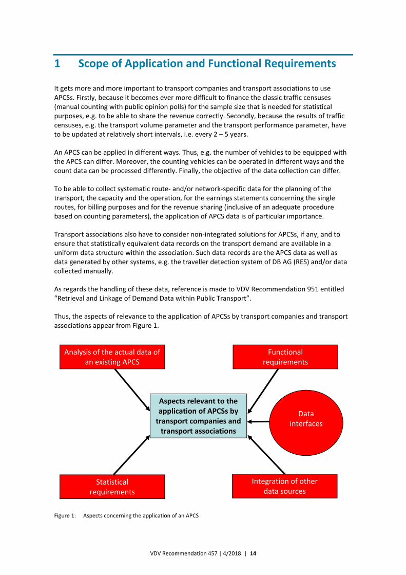
Thus, the aspects of relevance to the application of APCSs by transport companies and transport associations appear from Figure 1.
Figure 1: Aspects concerning the application of an APCS
Aspects relevant to the application of APCSs by transport companies and transport associations
Analysis of the actual data of an existing APCS
Functional requirements
Statistical requirements
Integration of other data sources
Data interfaces
VDV Recommendation 457 | 4/2018 | 15
The decision on the application of an APCS within a public transport system mainly depends on the results that can be achieved with the APCS, the accuracy of the APCS as well as the first costs for its implementation and the overheads for its operation in comparison or combination with conventional, manual data collection methods. This VDV Recommendation goes into detail with the data that can be retrieved by way of an APCS and with the statistical quality of an APCS.
Cost‐benefit aspects are not included in this VDV Recommendation.
It is explicitly noted that count data from an APCS cannot replace the results of traffic censuses with manual counting and opinion polls. This applies particularly to parameters like way chains, starting point‐destination relations, proportion values of the various kinds of fares and frequencies of use. Only the passengers can provide this information and therefore it can only be collected within the scope of an opinion poll. As regards the complementary connection between the two kinds of data collection – especially with a view to the revenue sharing within transport associations – reference is made to VDV Recommendation 951.
As far as the method presented in this VDV Recommendation goes, it can be ensured that:
— data from traffic flow collections with qualitative proportions (e.g. population proportion) can be updated via proportionality factors with count data from the APCS;
— data for qualitative parameters (e.g. population proportion) that cannot be retrieved from the APCS can be transformed to transport volume and/or transport performance data on the basis of the data collected by the APCS.
Moreover, it has to be ensured that data counted manually, e.g. on:
— courses or line variants operated by other contractors (who do not use APCSs or whose systems cannot be adapted or have not been approved);
— hailed shared taxis and door‐to‐door services, which cannot be counted as they cannot be technically assigned to timetables,
can be entered into the APCS background system and checked, processed and extrapolated in accordance with mathematical‐statistically reliable methods. In this respect reference is made to the requirements for the framework specification of APCS background systems specified in Annex D.
It also has to be considered that, in the long term, methods for detection of the passenger flows will be available in the form of the system concepts defined within the scope of the VDV Core Application (development variant 3b), which will make common passenger counting superfluous. However, there is no critical overlapping of the systems at the state of the art and with the present time frame. Further information is given in the “VDV‐Kernapplikation – Machbarkeits‐studie In‐Out‐Systeme (MIOS)” (en:Feasibility Study of In‐out Systems on the Basis of the VDV Core Application), which was prepared by VDV Kernapplikations GmbH & Co. KG on behalf of the Federal Ministry of Transport, Building and Urban Development (BMVBS).
From a statistical point of view, it has to be borne in mind that the results generated by APCSs in a sample
— are expected, estimated values that occur at a defined accuracy (determined by the relative sampling errors) and at a defined probability (determined by the confidence level) as a population;
— include accidental counting errors.
See 2.2 for further information.
VDV Recommendation 457 | 4/2018 | 16
The following results are available for the periods defined:
— transport volume in persons (P), i.e. the number of persons transported on a certain route is counted;
— occupation of the vehicle, which is calculated on the basis of the transport volume;
— the transport performance in passenger kilometres (Pkm), which is calculated with the help of a distance matrix.
The following can be aggregated/derived on the basis of the above‐mentioned results:
— the mean transport distance per person transported on a certain route (direct aggregation);
— the mean transport distance per person transported on a certain route by a certain transport company (indirect derivation with the help of the transfer factors to be determined within the scope of an opinion poll).
Moreover, extrapolated results can be generated for the transport volume and/or the transport performance for spatially limited units (fare zones, territorial entities etc.). The results are of importance both as values collected directly and as extrapolated values.
Therefore, the complete APCS shall ensure that the necessary statistical quality is reliably achieved upon completion of all process steps. This does not only apply to the population, but also to the single parameters and the single transport companies as well as the necessary extrapolations.
Thus, it has to be ensured that the APCS data can, above all, be used as expected, estimated values
— by the transport companies and competent authorities for their planning of capacities and transport services (with consideration of all requirements for application of the data in respect of confidentiality protection and competition);
— for revenue‐sharing parameters, inclusive of updating and demand‐oriented keys for cost‐sharing;
— for the update of traffic censuses via proportionality factors;
— for line‐success calculations and/or transport performance financing contracts;
— for the stratum‐bound merging of opinion poll data collected manually within the scope of traffic censuses.
It is explicitly noted that the application of an APCS involves complex technical and organisational processes and courses of action, which have to be permanently checked and controlled.
Annex A includes a check list for the quality management concerning the operation of an APCS, from which it appears which quality assurance processes have to be realised during the operation and considered in the decision‐making phase.
VDV Recommendation 457 | 4/2018 | 17
2 Statistical Requirements for the APCS
2.1 Overview
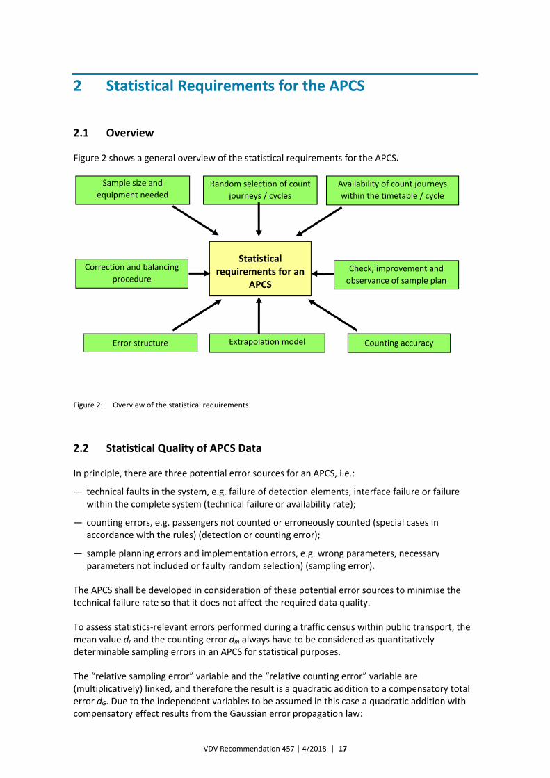
Figure 2 shows a general overview of the statistical requirements for the APCS.
Figure 2: Overview of the statistical requirements
2.2 Statistical Quality of APCS Data
In principle, there are three potential error sources for an APCS, i.e.:
— technical faults in the system, e.g. failure of detection elements, interface failure or failure within the complete system (technical failure or availability rate);
— counting errors, e.g. passengers not counted or erroneously counted (special cases in accordance with the rules) (detection or counting error);
— sample planning errors and implementation errors, e.g. wrong parameters, necessary parameters not included or faulty random selection) (sampling error).
The APCS shall be developed in consideration of these potential error sources to minimise the technical failure rate so that it does not affect the required data quality.
To assess statistics‐relevant errors performed during a traffic census within public transport, the mean value dr and the counting error dm always have to be considered as quantitatively determinable sampling errors in an APCS for statistical purposes.
The “relative sampling error” variable and the “relative counting error” variable are (multiplicatively) linked, and therefore the result is a quadratic addition to a compensatory total error dG. Due to the independent variables to be assumed in this case a quadratic addition with compensatory effect results from the Gaussian error propagation law:
Statistical requirements for an
APCS
Sample size and
equipment needed Availability of count journeys
within the timetable / cycle
Error structure Counting accuracy Extrapolation model
Random selection of count
journeys / cycles
Correction and balancing
procedure Check, improvement and
observance of sample plan
VDV Recommendation 457 | 4/2018 | 18
where
dG is the compensatory total error;
dr is the sampling error;
dm is the counting error.
This means that e.g. a relative sampling error of 3 % or 0.03 and a random counting error of 2 % or 0.02 are added to a compensatory total error of 3.6 % or 0.036.
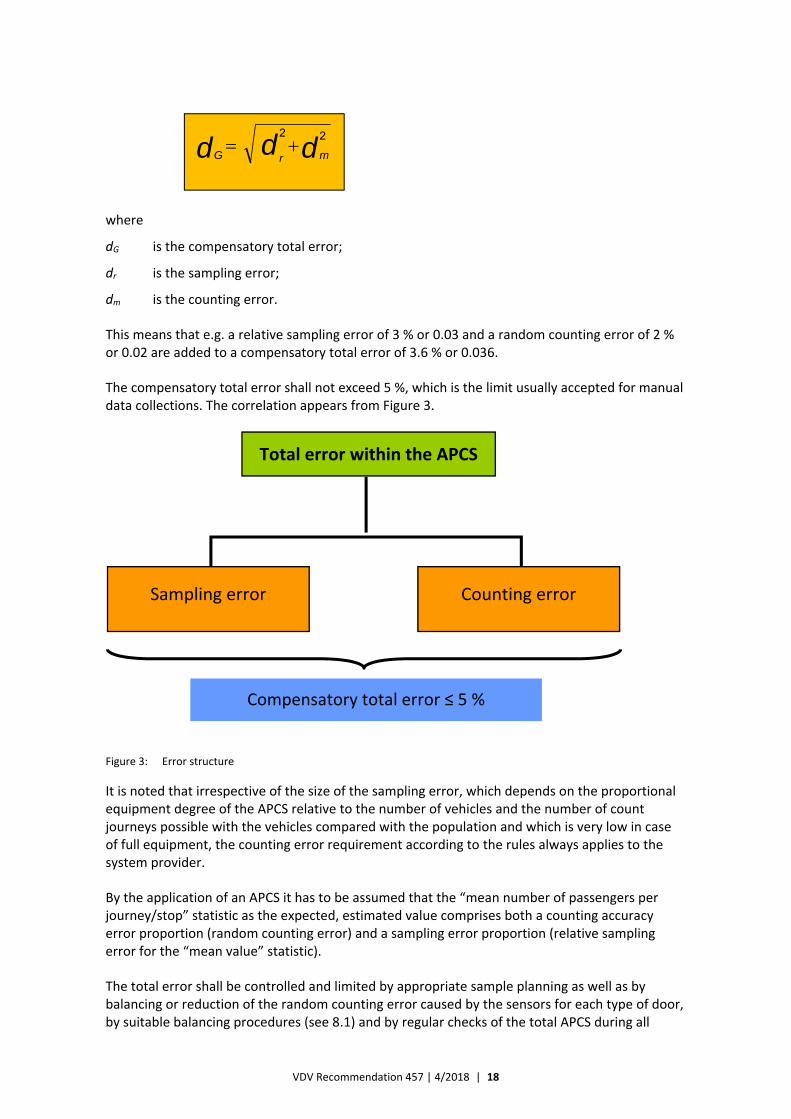
The compensatory total error shall not exceed 5 %, which is the limit usually accepted for manual data collections. The correlation appears from Figure 3.
Figure 3: Error structure
It is noted that irrespective of the size of the sampling error, which depends on the proportional equipment degree of the APCS relative to the number of vehicles and the number of count journeys possible with the vehicles compared with the population and which is very low in case of full equipment, the counting error requirement according to the rules always applies to the system provider.
By the application of an APCS it has to be assumed that the “mean number of passengers per journey/stop” statistic as the expected, estimated value comprises both a counting accuracy error proportion (random counting error) and a sampling error proportion (relative sampling error for the “mean value” statistic).
The total error shall be controlled and limited by appropriate sample planning as well as by balancing or reduction of the random counting error caused by the sensors for each type of door, by suitable balancing procedures (see 8.1) and by regular checks of the total APCS during all
Total error within the APCS
Sampling error Counting error
Compensatory total error ≤ 5 %
ddd mrG
22
VDV Recommendation 457 | 4/2018 | 19
process steps. Reference is made to Annex A entitled “Check List for the Quality Management concerning the Operation of the APCS”.
The success of these measures can be checked by way of:
— periodic or event‐related comparative counting to certify the counting accuracy, depending on the operational necessity in each single case due to modification of the technical equipment, the firmware or the organisation, e.g. readjustment of the sensors, application of new balancing methods;
— periodic re‐certification of the counting accuracy in the form of specific mathematical‐statistical procedures in the APCS background system in respect of the kind and the stringency of correlation between the reference functions of the automatically counted persons boarding or alighting;
— calculation and permanent verification of the sample size that is necessary for statistical purposes on the basis of the defined quality parameters and the actual relative spread to the mean value of persons boarding relative to the reference unit considered.
It is expected from an APCS that it generates expected, estimated values with minimum and maximum confidence limits for statistics of the P and Pkm parameters. At least the following statistical quality parameters are to be applied:
— confidence level of ≥ 95 %, i.e. S 0.95 (or 95 %)
— relative error of the population proportion, mean value ≤ 5 %, i.e.
dr 0.05 (or 5 %)
— relative spread as a relation to the spread to the mean value, i.e. V = 1.0 (or 100 %).
The relative spread is to be applied with reference to the standard deviation/mean value P (persons boarding) from a counting. This value shall either be calculated a priori in a statistically reliable way by way of a pilot sample to be verified in respect of its size and its stratification or it shall be taken over from available statistical analyses or it shall be estimated. From comparative counting it appears that a value of V = 100 % or 1.0 is acceptable if no quantified statement exists. It is highly recommended to verify the counting after its completion. To verify the necessary sample size and the resulting level of APCS equipment needed in the vehicles, it is also highly recommended to use relative spread parameters calculated on an appropriate mathematical‐statistical basis. Therefore, it is required that the relative spread is determined together with other statistical parameters (relative sampling error) of the APCS and that it is applied to the APCS for the permanent planning within the scope of the count journey planning.

VDV Recommendation 457 | 4/2018 | 20
3 Count Journey Planning Elements
3.1 Count Journey Planning in Case of Planned Availability
3.1.1 Assignment Criteria
The method of the count journey planning in case of planned availability, which is described below, is especially intended for buses, tramcars, light rail vehicles and metro vehicles operated within urban public transport.
The criteria for such an assignment are e.g. that
— each vehicle in a train consist is equipped with an APCS;
— the position of a counting vehicle in the train consist is known;
— counting vehicles can always be at disposal for a certain cycle;
— the number of vehicles in a train consist is relatively constant.
These conditions can also apply to other modes of transport, if appropriate.
3.1.2 Count Journey Planning
If the above‐mentioned criteria are fulfilled, the structure of the count journey planning in case of planned availability usually includes the four consecutive elements shown in Figure 4.
If the solutions are intended for transport associations, it is meaningful to include a superior control tool so that the general statistical conditions can be set and so that it is possible to check the realisation of the settings to achieve consistency and to ensure mutual confidentiality.
Figure 4: Structure of the count journey planning in case of planned availability
These four count journey planning elements can be united to two blocks, which leads to the following course of action:
Determination of the sample size (number of count journeys / cycles needed in the count period)
Random selection of count journeys / cycles among all planned journeys
Integration of the count journeys / cycles into the timetable
Check of the quality of the count journeys performed and correction, if necessary
VDV Recommendation 457 | 4/2018 | 21
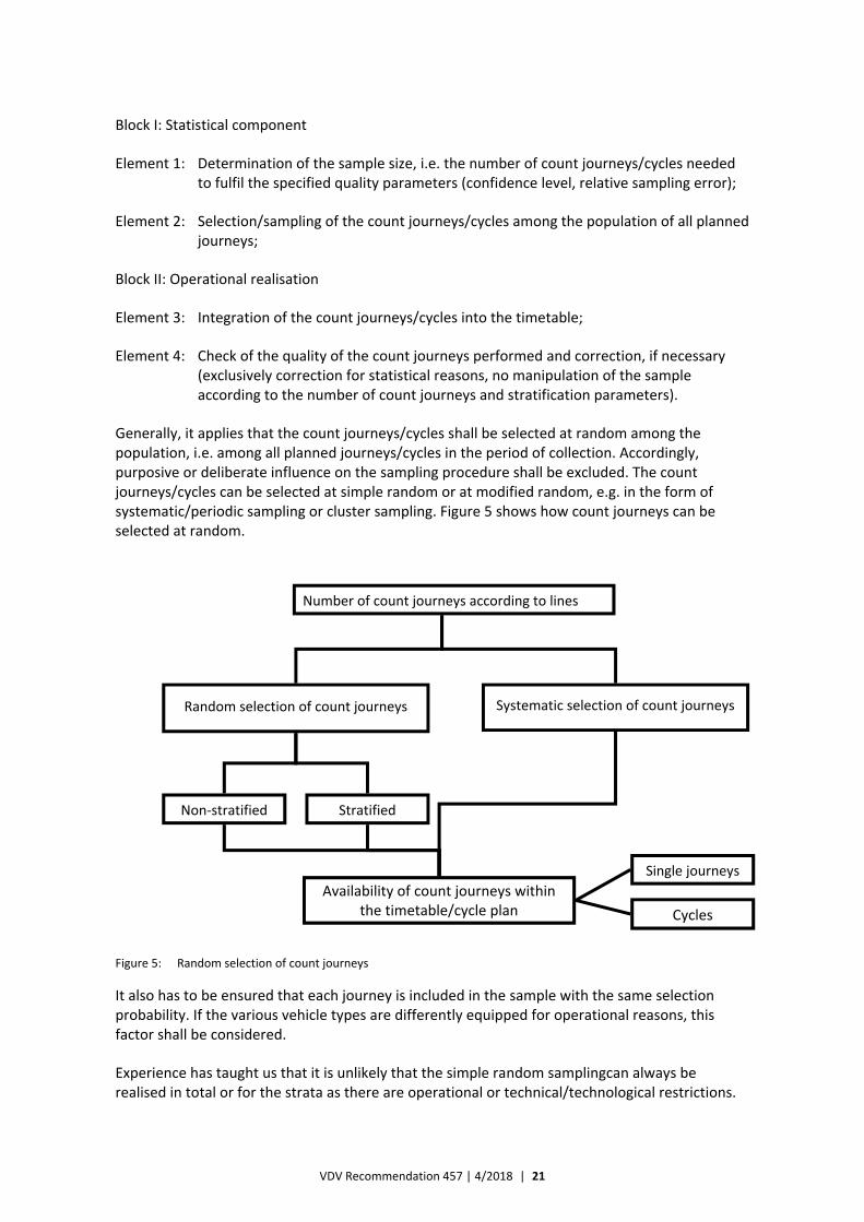
Block I: Statistical component
Element 1: Determination of the sample size, i.e. the number of count journeys/cycles needed to fulfil the specified quality parameters (confidence level, relative sampling error);
Element 2: Selection/sampling of the count journeys/cycles among the population of all planned journeys;
Block II: Operational realisation
Element 3: Integration of the count journeys/cycles into the timetable;
Element 4: Check of the quality of the count journeys performed and correction, if necessary (exclusively correction for statistical reasons, no manipulation of the sample according to the number of count journeys and stratification parameters).
Generally, it applies that the count journeys/cycles shall be selected at random among the population, i.e. among all planned journeys/cycles in the period of collection. Accordingly, purposive or deliberate influence on the sampling procedure shall be excluded. The count journeys/cycles can be selected at simple random or at modified random, e.g. in the form of systematic/periodic sampling or cluster sampling. Figure 5 shows how count journeys can be selected at random.
Figure 5: Random selection of count journeys
It also has to be ensured that each journey is included in the sample with the same selection probability. If the various vehicle types are differently equipped for operational reasons, this factor shall be considered.
Experience has taught us that it is unlikely that the simple random samplingcan always be realised in total or for the strata as there are operational or technical/technological restrictions.
Number of count journeys according to lines
Systematic selection of count journeys Random selection of count journeys
Non‐stratified Stratified
Availability of count journeys within the timetable/cycle plan
Single journeys
Cycles
VDV Recommendation 457 | 4/2018 | 22
The calls for tenders of the transport companies shall include appropriate specifications for the kind of day stratum and the time stratum, which correspond to the relevant specific conditions for the transport company in question.
Irrespective of the sampling procedure, a sample shall be generated by way of appropriate algorithms in the count journey planning via random selection and it shall be stratified proportionally to the population (i.e. all journeys in the count period) in respect of size and time. The strata of the sample are created inhomogeneously to one another and homogeneously as such. Possibilities of subsequent (dynamic) stratification for reduction of the spread of strata are listed in Annex D.
Rules for the handling and consideration of journeys that are unexpectedly performed by a counting vehicle out of the actual count journey planning shall be given in the specifications of the transport company in question.
3.2 Count Journey Planning in Case of Random Availability
3.2.1 Assignment Criteria
The method of the count journey planning in case of random availability, which is described below, is especially intended for regional rolling stock.
The criteria for such an assignment are e.g. that
— vehicles equipped with APCSs are operated in train consists in which not all vehicles are equipped with APCSs;
— the position of a counting vehicle in the train consist is not always known;
— counting vehicles cannot (always) be at disposal for a certain train movement or cycle;
— the number of vehicles in a train consist can deviate from the desired number;
— different vehicle types can be operated in different vehicle combinations;
— train units can be increased, reduced or branched during the regular journey.
These conditions can also apply to other modes of transport, if appropriate.
3.2.2 Count Journey Planning
In case of random availability of the vehicles equipped with APCSs in cycles there is no explicit count journey plan; the vehicles are integrated into cycles without considering the secondary conditions of the APCS (i.e. at random in respect of the APCS) and the resulting count data are evaluated for the result of the random sample.
To ensure that the sample specification is not observed a priori, it is very important to suitably plan the level of equipment needed and to strictly monitor the return of collected data. The calculation of the number of count journeys needed, i.e. the determination of the minimum sample size, is orientated towards the requirements for statistical accuracy and the desired stratification structure. Therefore, it does not differ from the recommendations given in 3.1.
In case of random availability, the minimum sample size cannot be purposively realised in a count journey plan. Therefore, the minimum number of count journey cycles (statistical requirement)
VDV Recommendation 457 | 4/2018 | 23
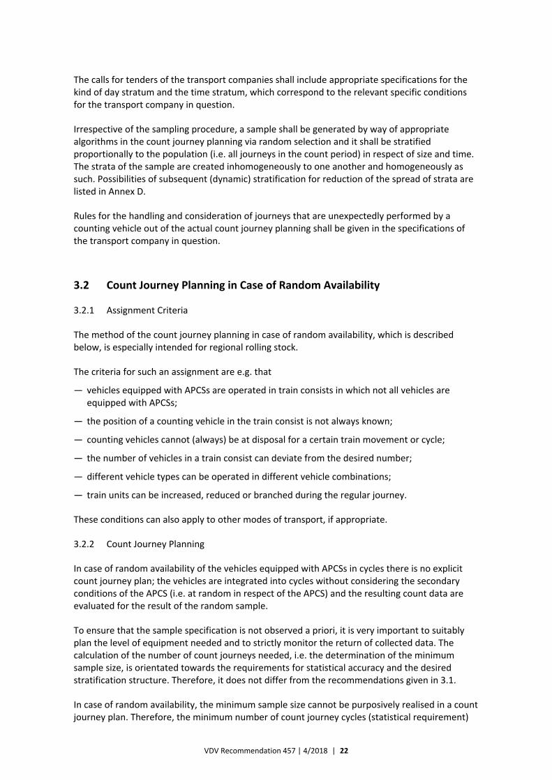
shall be ensured by a suitable – usually higher – proportion of vehicles equipped with APCSs. Usually, the additional collection for a big proportion of the train movements improves the quality of the data collected.
Considering the above‐mentioned conditions, the following structure of the count journey planning in case of random availability results. The elements in Figure 6 that are shaded in grey have been adapted in comparison with the situation described in 3.1 and the elements that are shaded in yellow are new supplementary elements.
Figure 6: Structure of the count journey planning in case of random availability
This overview is based on a train concept at the journey verification level. If the vehicle concept is applied, the sample made shall also be checked at the vehicle‐collecting level, especially if it cannot be verified that the vehicles can be placed at any position with the same probability.
Determination of the sample size (number of count journeys / cycles needed in the count period)
No APC‐specific planning of the count journeys / cycles among all planned journeys
Availability of the vehicles without considering secondary conditions of the APC (i.e. at random or independently in respect of the APC)
Check of the quality of the count journeys performed and correction, if necessary
Check of the sample made (comparison of the desired count journeys and the actual count journeys)
Verification of the random or equiprobable sampling of the actual count journeys in the sample proportional to the population
VDV Recommendation 457 | 4/2018 | 24
4 Sample Size and Level of Equipment Needed
4.1 Sample Size and Level of Equipment Needed in Case of Planned Availability
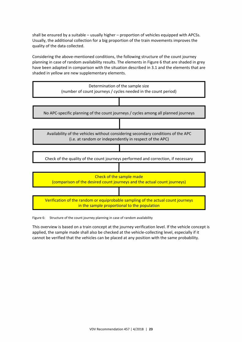
The statistical component for the application of an APCS results from the steps shown in Figure 7.
Figure 7: Sample size and level of equipment needed
4.1.1 Determination of the Sample Size
In step 1 the sample size needed n (i.e. the number of count journeys) is determined. It applies that n = f (S, dr, V). The sampling error dr and the confidence level S are the basic quality criteria of any sample‐based traffic census, inclusive of the APCS. Moreover, the relative spread V shall be considered as the spread quotient and the mean. The sample size per line, i.e. the number of necessary count journeys (or cycles), shall be determined in accordance with the specified quality parameters (confidence level, relative sampling error) for the count period for the count journey planning of the APCS in accordance with the general methodological principles of sample planning.
These principles and the most important sample planning variables in the heterograde case are described below. The sample planning is not explained in greater detail in this VDV Recommendation. Reference is made to the relevant statistical principles.
Usually, the sample size is determined by way of the following equation:
222
22
)1( rdNVkNVkn
(1)
where
n is the sample size (number of journeys/cycles) in the period of collection;
Step 1: Determination of the sample size (count journeys / cycles)
Step 3: Random selection of the count journeys / cycles according to the defined stratum structure
Step 2: Determination of the number of vehicles to be equipped with APCSs to cover the count journeys / cycles
VDV Recommendation 457 | 4/2018 | 25
V is the relative spread (spread/mean quotient);
dr is the maximum permissible relative sampling error;
k is the table value (depending on S = confidence level);
N is the number of journeys/cycles in the period of collection (population).
It shall be possible for the user to enter the variables for the confidence level and the relative sampling error in a variable and parameterisable way.
The most important variable of calculation step 1 for determination of the necessary sample size is the estimation of the spreads. It shall be possible for the user to use the “relative spread” parameter as a result variable generated by the APCS or to enter it variably. It can be based on secondary data from traffic censuses or drawn from these secondary data or it can be estimated.
As soon as count journey data are available, the real spread is to be drawn from the background system as the result variable. As a planning size for the relative spread in a reference application the relative spread of the passengers transported per journey can be set to V = 100 % (= 1.0). Thus, the planning of the size of count journeys needed for a first reference application is conservative. The other data are to be made available to the APCS by internal systems.
Necessary corrections shall be suitably considered in the count journey planning. For this purpose, the proportion of utilisable data records collected during the count journeys, the proportion of utilisable data records gathered from the technical application coefficient of the vehicles and the proportion of data records rejected in subsequent test procedures shall be considered.
Availability errors also lead to uncertainty. Therefore, it is proposed to increase the calculated sample size by a corrective, e.g. +10 %, which considers the practical problems with reduction of count journeys a priori.
4.1.2 Determination of the Level of Equipment Needed in the Vehicles
It is also necessary to determine the number of vehicles that have to be equipped with APCSs if the determined sample size is to be realised. The number of vehicles to be equipped with APCSs is determined by way of the following equation:
)()(
ZkFnAn
(2)
where
n(A) is the number of vehicles to be equipped with APCSs;
n is the number of count journeys needed for statistical purposes (sample size);
F is the number of count journeys that a vehicle equipped with an APCS can perform in the period of collection (journey period, failure ratio etc.);
k(Z) is the application coefficient of the APCS (e.g. APCS failure, generation of non‐utilisable data records).
By the determination of the F parameter the down time due to the maintenance of the vehicle (kilometric performance, technical supervisory authority, warranty periods, actual average down
VDV Recommendation 457 | 4/2018 | 26
times or down time according to experience) as well as the down time and maintenance of the vehicle specifically caused by the APCS shall be considered.
By the estimation of the k(Z) parameter it has to be considered that utilisable data might not be available although the counting has been made because data records have to be rejected in the subsequent test steps and balancing procedures. This difference shall be considered both in the sample planning and in the planning of the level of equipment needed.
The following parameters shall be considered in this connection:
— workshop reserve: coefficient considering the average failure frequency for usual technical reasons (preventive and corrective maintenance);
— operation reserve: coefficient considering non‐counting times for operational reasons (modification of the cycle plan in the form of e.g. exchange of vehicles, wrong position of the vehicle in the depot, non‐scheduled operation with any vehicle combination etc.);
— system reserve: coefficient considering system‐conditioned failures (faults in the raw data, failure/maloperation of system components, rejection of the journey during the transformation or the balancing due to non‐observance of the set parameters. In case of non‐autonomous systems with logical tracking via the distance: non‐detection of the journey due to operational, non‐plannable diversions).
If it is not possible to reliably determine these values, the following equation can be included in the calculation:
FcBAn )( (3)
where
n(A) is the number of vehicles to be equipped with APCSs;
B is the vehicle fleet;
c is the sampling fraction of the count journeys;
F is the increase factor to be considered due to e.g. the down times of the vehicles and non‐utilisable data (this parameter can be set to F = 2 according to experience from comparable cases within public transport).
Experience has taught us that it suffices to equip 10 % of the vehicle fleet with an APCS, but this figure may vary in the concrete case / for each concrete route and depends on the sample size and the restrictions (depots, vehicles, operation, cycle conditions).
4.2 Sample Size and Equipment Needed in Case of Random Availability
4.2.1 Equipment Strategy
For the count journey planning based on random availability it also applies to an APCS that suitable detection equipment shall be fitted at all doors of a vehicle so that all passengers boarding or alighting are registered and that it shall be possible to determine the occupation of the vehicle and thus the transport performance on the basis of the data collected by the APCS. As train‐units are restricted by driver’s cabs at both ends, all outer doors shall be equipped with APCSs. By analogy, this also applies to buses and tramcars.
VDV Recommendation 457 | 4/2018 | 27
In regional rail transport locomotive‐hauled passenger coaches are often operated. Such a train formation consists of many single vehicles, which can be combined to a train consist in nearly any way. Each single passenger coach can be boarded and alighted via outer doors and – at the end of each coach – via transition doors 0F
1.
If APC equipment is fitted at all outer doors of all passenger coaches in a train consist, such a train can be regarded as one train‐unit from an APCS aspect, which means that all rules for train‐units can be applied.
If it is intended to realise such an equipment strategy (“train concept”), it is important to bear in mind that the APCS is defective for the entire train as soon as a single door is not monitored. Apart from any functional malfunction of the APCS door equipment this means that the APCS only functions if no coach without an APCS is integrated into the train consist. To achieve reliable application of a train concept, it has to be ensured – for the entire life of the APCS – that only passenger coaches equipped with APCSs make up a train consist and that a defect coach is only replaced by a coach equipped with an APCS.
Thus, to ensure that the investment pays in the long term, it is important to consider whether the concrete train formation will remain predictable for a very long time.
As an alternative to the train concept each single passenger coach can be regarded as a separate, autonomous vehicle (“vehicle concept”). In this case APC equipment shall be fitted at all outer doors and all transition doors. If a coach is defective, only the count result of a single coach and not that of a complete train is missing.
If the APCS of a passenger coach is fully autonomous and if all accesses to a coach are monitored electronically, the vehicle concept can be handled in the same way as the concept for motor vehicles in multiple traction. However, the additional requirements specified in chapter 9 shall be observed.
Thus, in case of the vehicle concept it is not necessary to equip all passenger coaches of a train with an APCS and therefore the train formation only has to be considered to a certain degree2. In this case the APCS also functions if a defect coach equipped with an APCS is replaced by a coach not equipped with an APCS or if the train formation has to be adapted due to a modified market structure.
4.2.2 Determination of the Level of Equipment Needed in the Vehicles
To determine how much equipment is needed in the vehicles in case of random availability of the counting vehicles according to the calculation formula mentioned in 4.1.2, a factor shall be added that considers the degree of deviation of operation of the vehicles from the equal distribution and thus increases the level of equipment needed.
Thus, the following equation applies:
VZkF
nAn (4)
1 Generally, “transition doors” are all doors or passenger transitions that can be used during the journey.
2 Of course, it has to be ensured that a sufficient number of coaches equipped with APCSs is operated.
VDV Recommendation 457 | 4/2018 | 28
where
n(A) is the number of vehicles to be equipped with APCSs;
n is the number of count journeys needed for statistical purposes (minimum sample size);
F is the number of count journeys that a vehicle equipped with an APCS can perform in the period of collection (journey period, failure quote etc.);
k(Z) is the application coefficient of the APC equipment (e.g. APCS failure, generation of non‐utilisable data records);
V : is the correction factor due to the lack of availability.
Due to empirical data it is estimated that V amounts to 2 for regional rail transport. Thus, to collect the minimum data, twice as much APC equipment is needed in vehicles for regional rail transport, provided that the other conditions are the same. This means that some strata are served by vehicles equipped below average and that the probability increases that the sample size to be realised according to the statistical requirement is not reached in the smallest stratum. Consequently, the so‐called APCS network collapses for operational reasons because vehicles are operated in several, rather disjoint (i.e. separate) partial networks although the vehicles are operated at random. In such a case each partial network is to be considered as an independent network by the determination of the level of equipment needed in the vehicles and by the assignment of the vehicles equipped.
Usually, it is very difficult to estimate the size of the correction factor without further examination, especially in case of complex networks. Therefore, it is highly recommended to validate the estimation of the level of equipment needed in the vehicles by way of comprehensive simulation calculations before an APCS is put into operation.
If relevant vehicle operation data from past periods are available, they should be processed and vehicles should be virtually marked at random according to the Monte Carlo method as vehicles equipped with APCSs. Then it can be assumed that count data are available for all marked vehicles in the real applications3. Thereafter, these performance blocks are analysed to find out to which degree they would fulfil the necessary sample size, i.e. whether train movement data were fully collected and whether the distribution according to train numbers or line and weekday groups corresponds to the specification.
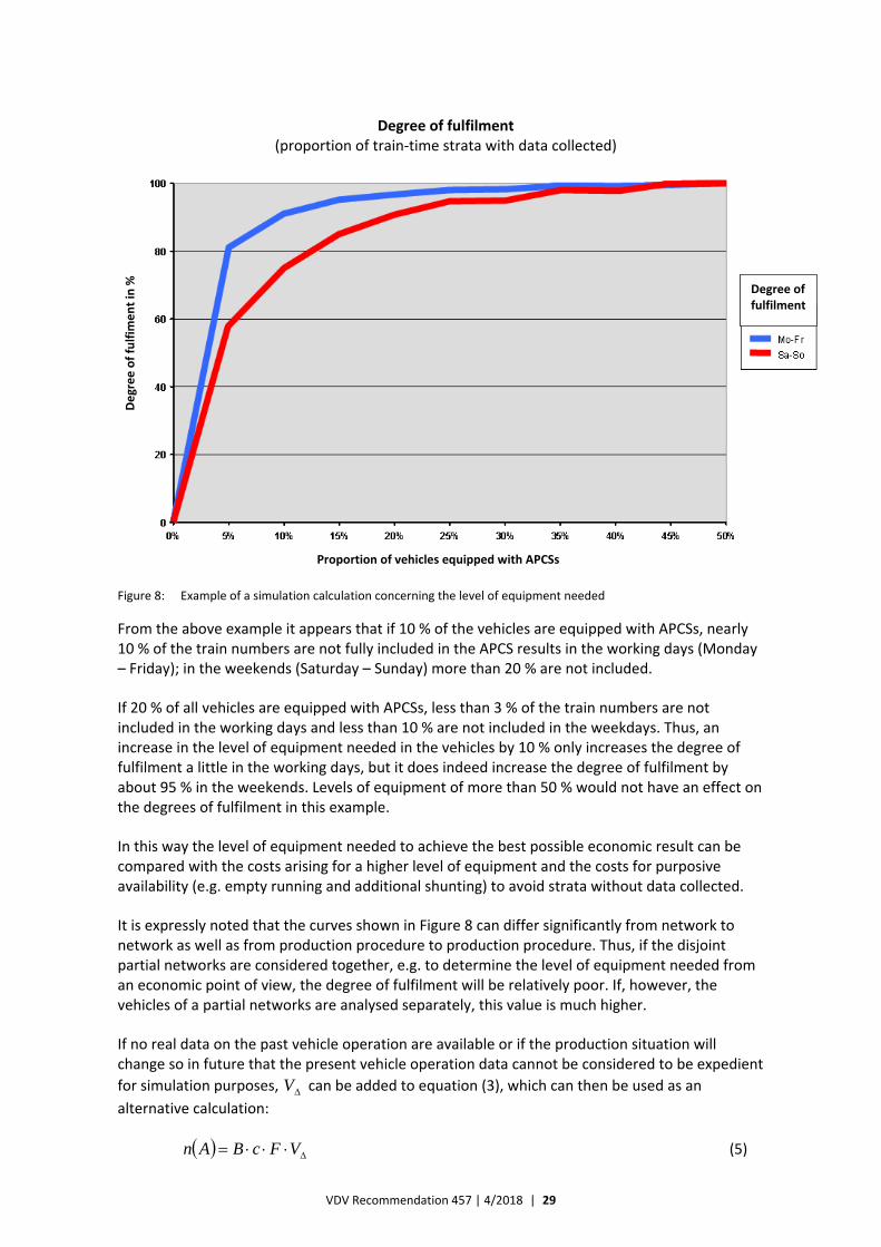
If such a simulation is repeated a sufficient number of times, also with different levels of equipment needed, stable estimated values concerning the degree of fulfilment of the sample specification can be derived, which also include all interruptions of real train operation. Figure 8 shows a fictive example of such a simulation calculation for a stratification structure based on single train numbers and weekday groups.
3 If necessary, this value can be reduced by the application coefficient of the APC equipment mentioned in 4.1.2.
VDV Recommendation 457 | 4/2018 | 29
Figure 8: Example of a simulation calculation concerning the level of equipment needed
From the above example it appears that if 10 % of the vehicles are equipped with APCSs, nearly 10 % of the train numbers are not fully included in the APCS results in the working days (Monday – Friday); in the weekends (Saturday – Sunday) more than 20 % are not included.
If 20 % of all vehicles are equipped with APCSs, less than 3 % of the train numbers are not included in the working days and less than 10 % are not included in the weekdays. Thus, an increase in the level of equipment needed in the vehicles by 10 % only increases the degree of fulfilment a little in the working days, but it does indeed increase the degree of fulfilment by about 95 % in the weekends. Levels of equipment of more than 50 % would not have an effect on the degrees of fulfilment in this example.
In this way the level of equipment needed to achieve the best possible economic result can be compared with the costs arising for a higher level of equipment and the costs for purposive availability (e.g. empty running and additional shunting) to avoid strata without data collected.
It is expressly noted that the curves shown in Figure 8 can differ significantly from network to network as well as from production procedure to production procedure. Thus, if the disjoint partial networks are considered together, e.g. to determine the level of equipment needed from an economic point of view, the degree of fulfilment will be relatively poor. If, however, the vehicles of a partial networks are analysed separately, this value is much higher.
If no real data on the past vehicle operation are available or if the production situation will change so in future that the present vehicle operation data cannot be considered to be expedient
for simulation purposes, V can be added to equation (3), which can then be used as an
alternative calculation:
VFcBAn (5)
Degree of fulfilment (proportion of train‐time strata with data collected)
Degree of fulfim
ent in %
Degree of fulfilment
Proportion of vehicles equipped with APCSs
VDV Recommendation 457 | 4/2018 | 30
where
n(A) is the number of vehicles to be equipped with APCSs;
B is the vehicle fleet;
c is the sampling fraction of the count journeys;
F is the increase factor to be considered due to e.g. the down times of the vehicles and non‐utilisable data (this parameter can be set to F = 2 according to experience from comparable cases within public transport).
V : is the correction factor due to the lack of availability.
In most applications the correction factor V lies between 1 and 4. If the recommendations in
4.1. are followed, the optimal level of equipment needed lies between 10 % and 40 %. To estimate the level of equipment needed as exactly as possible, the general technical conditions (e.g. distribution of the depots, structure of the network and the vehicle cycles, kind of vehicles and operating conditions for the vehicles) are to be examined and considered.
It is noted that the equations refer to the selected concept, i.e. either to the train concept or to the vehicle concept. In case of a train concept the population is the number of all trains in the sample period. In case of a vehicle concept the population is the number of all vehicles in the sample period. As regards the level of equipment needed for statistical purposes the availability of vehicles equipped with APCSs in a train shall also be considered.
VDV Recommendation 457 | 4/2018 | 31
5 Availability of Count Journeys in the Timetable/Cycle
5.1 Plannable Availability of Count Journeys
Count journeys shall be so planned that it is ensured that the count journeys selected at random among the population of planned journeys are reliably and firmly included in the operation in the form of single or clustered count journeys. If the timetable data are considered, the availability of the relevant planning systems shall be checked in advance. Various kinds of clusters can be made, e.g. timetable days, timetable half‐days or cycles.
Further availability restrictions shall be observed, e.g. depot dependency due to workshop capacities or blocking of routes or route sections for single types of vehicles e.g. due to the condition of the road in question or due to a contract with a third party to operate certain vehicles on certain lines for advertising purposes or due to the traction (coaches/vehicles that cannot be coupled to one another).
Moreover, some general operating conditions have to be considered:
— driver‐vehicle dependency due to special services (e.g. parking in the open);
— cycle connections (e.g. connection of partial cycles to extend or shorten trains);
— ability of vehicles to make dynamic depot changes;
— separate availability according to depots and/or vehicle types;
— scheduled diversions (e.g. in case of dependency between non‐autonomous systems and the master system in the vehicle, e.g. supply of master data by the AVMS/ITCS);
— exchange of vehicles;
— exclusion of cycles with irrelevant journeys (e.g. no transport association fare and journeys not covered by Section 42 of the German Law on Passenger Transport (PBfG)).
5.2 Random Availability of Count Journeys
Usually, count journeys with random availability of the vehicles equipped with APCSs are not planned. However, the count data collected during count journeys at random availability shall be continuously and carefully monitored to fulfil the minimum sample size.
VDV Recommendation 457 | 4/2018 | 32
6 Check and Correction of the Quality of Count Journeys
6.1 Check and Correction in Case of Planned Availability
It is important for the acceptance and statistical significance of the sample planning and the sample performance that they are verified on the basis of both the count journeys actually performed and defined strata parameters. In practice, it has turned out that planned count journeys cannot always be realised for various reasons, which has been considered to a sufficient degree.
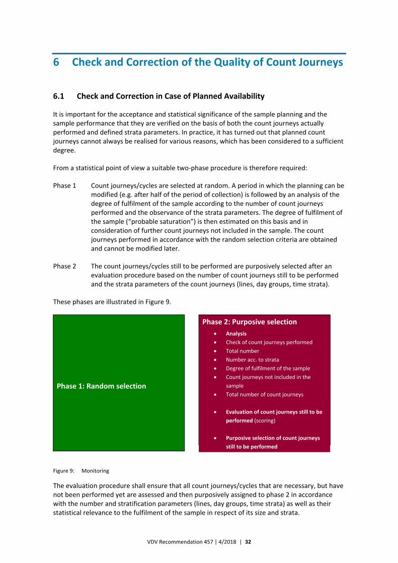
From a statistical point of view a suitable two‐phase procedure is therefore required:
Phase 1 Count journeys/cycles are selected at random. A period in which the planning can be modified (e.g. after half of the period of collection) is followed by an analysis of the degree of fulfilment of the sample according to the number of count journeys performed and the observance of the strata parameters. The degree of fulfilment of the sample (“probable saturation”) is then estimated on this basis and in consideration of further count journeys not included in the sample. The count journeys performed in accordance with the random selection criteria are obtained and cannot be modified later.
Phase 2 The count journeys/cycles still to be performed are purposively selected after an evaluation procedure based on the number of count journeys still to be performed and the strata parameters of the count journeys (lines, day groups, time strata).
These phases are illustrated in Figure 9.
Figure 9: Monitoring
The evaluation procedure shall ensure that all count journeys/cycles that are necessary, but have not been performed yet are assessed and then purposively assigned to phase 2 in accordance with the number and stratification parameters (lines, day groups, time strata) as well as their statistical relevance to the fulfilment of the sample in respect of its size and strata.
Phase 1: Random selection
Phase 2: Purposive selection
Analysis
Check of count journeys performed
Total number
Number acc. to strata
Degree of fulfilment of the sample
Count journeys not included in the
sample
Total number of count journeys
Evaluation of count journeys still to be
performed (scoring)
Purposive selection of count journeys
still to be performed
VDV Recommendation 457 | 4/2018 | 33
Thus, it has to be ensured that a sample proportional to the population in respect of size and strata is realised on the basis of phase 1 (random selection) and phase 2 (purposive selection).
6.2 Check and Correction in Case of Random Availability
Instead of random selection of count journeys/cycles (phase 1 acc. to 6.1) vehicles are selected without consideration of whether they are equipped with APCSs or not.
The degree of fulfilment of the sample specificationF
4 and especially the equal distribution of the count journeys across all strata over time – as in case of the purposive availability of vehicles – are permanently monitored.
The following shall be documented:
a) minimum number of count journeys to be performed per stratum and count period (count
journeys planned = minimum sample size);
b) number of successful count journeys per stratum and count period (count journeys
performed).
In this way it can be checked and verified whether the vehicles equipped with APCSs were systematically and purposively assigned to certain cycles – contrary to the explicit requirement – in the normal process. Moreover, non‐fulfilment of the sample specification can be determined and phase 2 (“purposive selection”) can – in exceptional cases – be initiated in the form of a requirements list to the vehicle depot manager towards the end of the period considered. Thus, purposive availability can also occur in exceptional cases.
The observance of the sample specification can be verified by checking the sample realised and the random or equiprobable selection of the count journeys proportional to the population in the count sample. It is noted that the verification shall also be made for APCSs with full availability of the vehicles in identical ways. In the end this means verification of the compilation of a count journey plan based on random selection as well as its realisation.
The following shall be verified:
a) Fulfilment of the sample according to the number of count journeys in the count period in
compliance with the valid specification for the sampling error and the confidence level as
well as according to the sample sizes relative to the population, which are to be mentioned
by the regional rail transport company (number of all journeys in the period of collection),
and the variation coefficient.
For this purpose, the following parameters shall be known:
‐ n i.e. the sample size realised (number of count journeys performed);
‐ N i.e. the number of journeys/cycles in the period of collection (population);
‐ dr i.e. the relative sampling error realised;
‐ V i.e. the relative spread realised (spread/mean quotient P).
4 Consideration of the requirements for sampling errors and the confidence level (cf. 2.2)
VDV Recommendation 457 | 4/2018 | 34
b) Selection of the count journeys/cycles from the population at random as well as exclusionF
5
of purposive or deliberate influence on the selection and thus observance of the principle of
equal selection probability to all journeys.
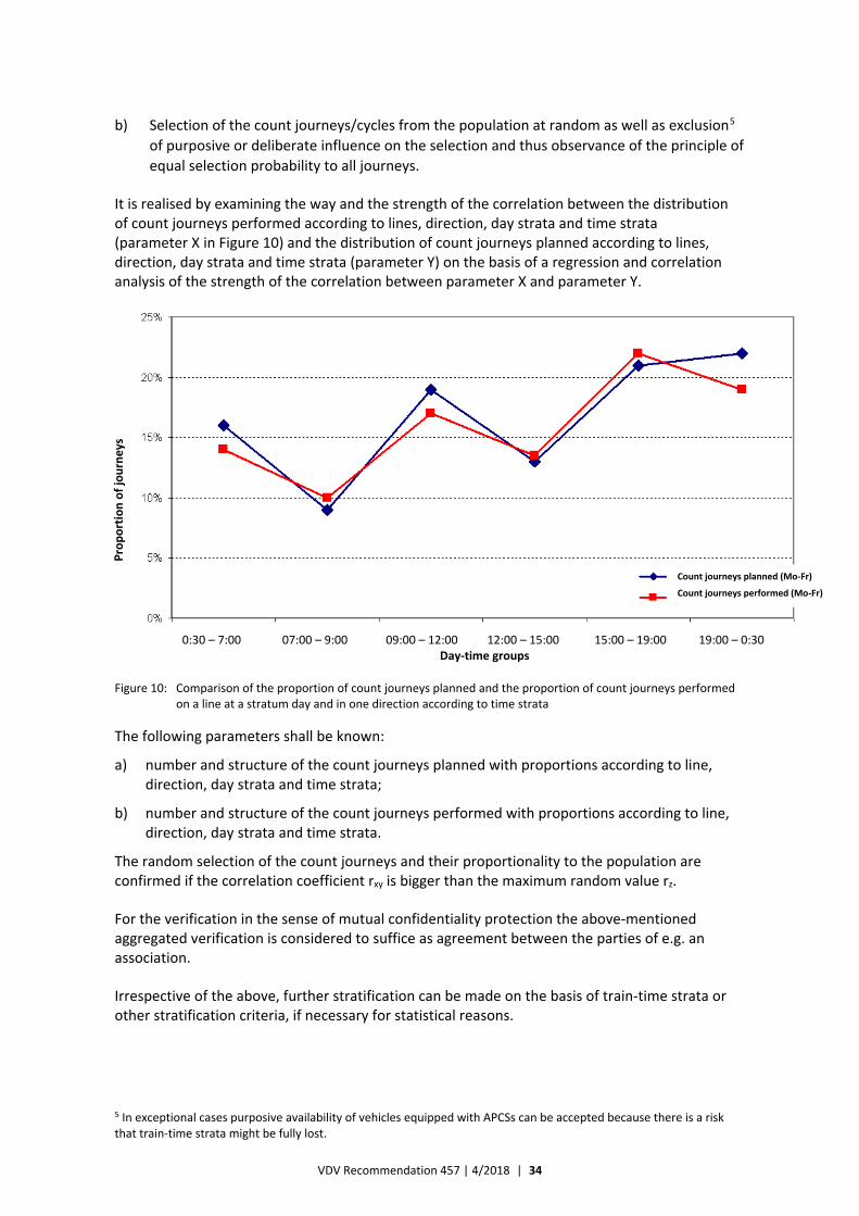
It is realised by examining the way and the strength of the correlation between the distribution of count journeys performed according to lines, direction, day strata and time strata (parameter X in Figure 10) and the distribution of count journeys planned according to lines, direction, day strata and time strata (parameter Y) on the basis of a regression and correlation analysis of the strength of the correlation between parameter X and parameter Y.
Figure 10: Comparison of the proportion of count journeys planned and the proportion of count journeys performed on a line at a stratum day and in one direction according to time strata
The following parameters shall be known:
a) number and structure of the count journeys planned with proportions according to line, direction, day strata and time strata;
b) number and structure of the count journeys performed with proportions according to line, direction, day strata and time strata.
The random selection of the count journeys and their proportionality to the population are confirmed if the correlation coefficient rxy is bigger than the maximum random value rz.
For the verification in the sense of mutual confidentiality protection the above‐mentioned aggregated verification is considered to suffice as agreement between the parties of e.g. an association.
Irrespective of the above, further stratification can be made on the basis of train‐time strata or other stratification criteria, if necessary for statistical reasons.
5 In exceptional cases purposive availability of vehicles equipped with APCSs can be accepted because there is a risk that train‐time strata might be fully lost.
Proportion of journeys
Count journeys planned (Mo‐Fr)
Count journeys performed (Mo‐Fr)
0:30 – 7:00 07:00 – 9:00 09:00 – 12:00 12:00 – 15:00 15:00 – 19:00 19:00 – 0:30 Day‐time groups
VDV Recommendation 457 | 4/2018 | 35
7 Requirements for the Counting Accuracy
When an APCS is introduced, its counting accuracy has to be defined mathematical‐statistically. Moreover, the counting accuracy of the APCS shall be verified when it has been installed.
The counting accuracy of the APCS is decided by counting the passengers boarding and alighting at the doors. Systematic deviations or errors (tendency to count too many or too few passengers) and random errors can occur.
To observe the counting accuracy of the APCS in respect of the “transport volume” (P) parameter and the “transport performance” (Pkm) parameter, the following barriers have to be observed at the counting vehicle category verification level:
a) the differences in the sums of the automatic count values of passengers boarding and alighting at all halts during all count journeys shall not exceed 1 % of the manual count values per category of counting vehicles (vehicle type or door type);
b) ≤ 5 % of all door halts shall be faulty; a door halt is faulty if it deviates more than one third [33.3 %] from the value counted manually and if it also deviates by more than one person; or
c) ≤ 5 % of all halts of a counting vehicle shall be faulty; a single result of all doors of a counting vehicle at a halt is regarded as faulty if it deviates more than 20 % from the value counted manually and if it also deviates by more than one person;
d) the statistical test of the statistical non‐distortion shall be performed on the basis of the equivalence test and thus exclude the existence of systematic errors.
As regards all other requirements, methodical rules and requirements for certifying the counting accuracy and for applying the equivalence test, inclusive of an example, reference is made to Annex B entitled “Rules for Verifying and Certifying the Counting Accuracy”.
VDV Recommendation 457 | 4/2018 | 36
8 Correction and Balancing Procedure
8.1 Balance Settlement
Appropriate plausibility and correction procedures have to be implemented into the APCS.
The statistical requirements for the algorithm have to be specified in respect of balance settlement via software.
To balance random counting errors and to ensure the plausibility, the balance between passengers boarding and passengers alighting shall be settled after a suitable balance algorithm for all journeys assigned and to be corrected. This balance algorithm can only balance differences between passengers boarding and passengers alighting that have been defined in the requirements for the counting accuracy and that have been caused by the permitted random counting errors.
The algorithm for balance settlement shall not be used to balance a big difference between passengers boarding and passengers alighting that has arisen for another reason, e.g. due to systematic errors or big deviations from the permitted (defined) counting errors. Therefore, it is important to ensure that big differences in the balance that have arisen from such errors are detected when the data are verified and that the affected count journeys are deleted. It shall be possible to parameterise these settings in the APCS as the number of passengers boarding and alighting can be rather low in regional rail transport or at the beginning/end of the daily operation within urban transport.
Moreover, it shall be examined for the journey/journey chain whether the balance difference reaches a set value valid for the error defined. Journeys that exceed such a set value shall be deleted and shall not be included in the balance settlement. This setting shall be parameterised in the APCS.
In this way it gets obvious whether the reason for a deviation in the result is caused by an error of the APCS (sensors) or by an error of the algorithm for the balance settlement (software).
The algorithm for the balance settlement shall ensure that
— there are no negative occupation values;
— the balance is settled in the narrow sense, i.e. in the sense of removal of a positive final occupation value (of a journey or a journey chain in the form of “persons who remain seated”),
according the principles of simplicity, transparency, interpretability of the variables and traceability and with the expectation that the erroneous value for boarding is identical with that for alighting.
A procedure with the following logical steps, which are only specified in general terms in this VDV Recommendation, shall be applied.
These steps shall be examined under real conditions and determined accordingly. They are not explained in great detail because the solutions already include the providers’ specific know‐how. This also applies to the fact that it shall not only be possible to balance journeys, but also journey chains.

VDV Recommendation 457 | 4/2018 | 37
a) In principle, passengers alighting (A) at the first stop and passengers boarding (B) at the last stop are set to 0 if no passenger should then stay in the vehicle according to the plan (“persons who remain seated”). In case of a journey chain passengers alighting (A) at the first stop of the first journey of a journey chain and passengers boarding (B) at the last stop of the last journey of the journey chain are set to 0.
b) The mean of the sum of passengers boarding and the sum of passengers alighting as well as the correction of the difference amounts to B ≠ A both for the passengers boarding and for the passengers alighting
— due to the principle of lack of reason at all stops;
— according to a random selection at defined stops;
— according to the probability of occupation at the stops at which most passengers board and alight;
— due to further plausibility criteria.
c) No negative occupation values are allowed.
Important points of the algorithm for balance settlement in case of balance differences arisen exclusively due to random counting errors are the balance settlement according to the mean of the sum of passengers boarding and the sum of passengers alighting and the decision on a correction stop. It is not allowed to settle the balance on the basis of the highest or lowest value or only on the basis of the value of passengers boarding or alighting.
8.2 Waiting Room Effect
In principle, the counting sensors cannot register whether the same passenger boards and alights several times at the same halt. Therefore, it is not possible either to directly realise the per se meaningful requirement only to count persons boarding at a station of a train movement if they are still in the train in the adjacent section of movement, i.e. persons who did not alight again before the train departs, as passengers boarding. The same applies to the requirement only to count persons who stayed in the previous section of movement as passengers alighting.
Thus, it can occur that a person boards a train and then alights at the same station, i.e. that he/she uses the train as a waiting room. This is the case if
— the train stops for a relatively long time at the station;
— there are only few alternative possibilities of stay at the station.
Therefore, only persons who leave the train during its halt phase within a fixed period after the arrival of the train shall be regarded as passengers alighting. It shall be assumed that persons who leave the train after this period boarded it at the same halt (i.e. that they use the train as a waiting room).
Thus, it shall be required that count values are available for passengers boarding and alighting within a fixed period after the arrival of the train and for passengers boarding and alighting after this period, respectively.
This procedure relates to the outer doors that determine the station load in the two periods and to the balance of the transition doors for the halt phase; the negative balance is assigned to the passengers alighting and the positive to the ones boarding.
VDV Recommendation 457 | 4/2018 | 38
9 Possible Standard Solutions for Special Operating/ Technical Cases
9.1 Cases Specific to Public Transport
Experience has taught us that there might be certain special cases by the detection of transport volumes and transport performances, which depend on the operating or technical conditions as well as further general conditions (also due to methodical rules concerning the revenue‐sharing process). There is no standard solution for these special cases, but standardisation should be strived for.
Standard solutions should be offered at least for the detection of the transport volume and the transport performance. Thus, e.g. the following should be considered:
— differentiated spatial proportions (e.g. fare zones) allowing for occupation (also virtual passengers boarding in a subsequent fare zone if the fare zone border is passed) as well as passengers boarding and alighting;
— association areas allowing for journeys into and out of these areas;
— association areas allowing for zone borders as well as special transport areas within the fare zones (e.g. urban transport in a small area);
— ring lines or other adequate linking of journeys provided by the timetable, the roster or the cycle plan;
— overcrowding of vehicles (passengers who alight and reboard to allow the passenger turnaround);
— territorial entities (e.g. counties) for settlement of enterprise‐specific transport performances on behalf of e.g. competent authorities;
— turning circles;
— twin stops (halts twice at one stop within the line course or two halts at the same stop, e.g. at the terminal stop and the first stop).
These requirements shall be specified in great detail in the specifications.
9.2 Cases Specific to Regional Rail Transport
9.2.1 Production Form
Regional rail transport can be performed very differently. Contrary to buses and tramcars, trains operated within regional rail transport often
— consist of several vehicles;
— include different types;
— have two coach classes.
Moreover, there are many different type series with different technical conditions and different door geometries.
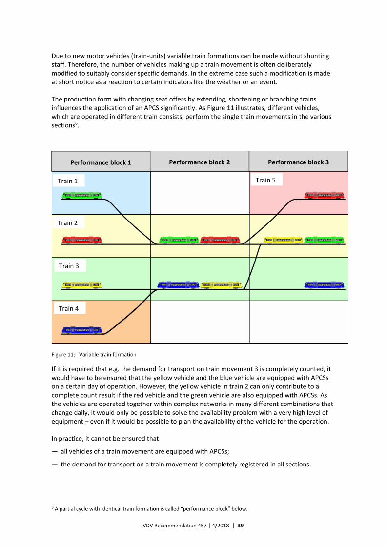
VDV Recommendation 457 | 4/2018 | 39
Due to new motor vehicles (train‐units) variable train formations can be made without shunting staff. Therefore, the number of vehicles making up a train movement is often deliberately modified to suitably consider specific demands. In the extreme case such a modification is made at short notice as a reaction to certain indicators like the weather or an event.
The production form with changing seat offers by extending, shortening or branching trains influences the application of an APCS significantly. As Figure 11 illustrates, different vehicles, which are operated in different train consists, perform the single train movements in the various sections6.
Figure 11: Variable train formation
If it is required that e.g. the demand for transport on train movement 3 is completely counted, it would have to be ensured that the yellow vehicle and the blue vehicle are equipped with APCSs on a certain day of operation. However, the yellow vehicle in train 2 can only contribute to a complete count result if the red vehicle and the green vehicle are also equipped with APCSs. As the vehicles are operated together within complex networks in many different combinations that change daily, it would only be possible to solve the availability problem with a very high level of equipment – even if it would be possible to plan the availability of the vehicle for the operation.
In practice, it cannot be ensured that
— all vehicles of a train movement are equipped with APCSs;
— the demand for transport on a train movement is completely registered in all sections.
6 A partial cycle with identical train formation is called “performance block” below.
Performance block 1 Performance block 2 Performance block 3
Train 1
Train 2
Train 3
Train 4
Train 5
VDV Recommendation 457 | 4/2018 | 40
Consequently, the proportion to be examined has to be modified from the complete train movement to a section of the train movement, i.e. to a so‐called performance block. Then the APCS provides:
— data collected for single performance block movements;
— data collected for parts of the seat offer in case of multiple traction.
Thus, a train result consists of several performance block movements made during several days. It has to be born in mind that not all parts of the train movement might provide utilisable data. The evaluation of values for these parts of the train movement shall be made via suitable procedures.
9.2.2 Offer Concepts
Sometimes the availability of rail vehicles is planned for cycles of several days, which serve many single train movements. If the train number is changed, the passengers alighting shall be assigned to the number for the train arriving and the passengers boarding to the train departing.
If the train stands still for a relatively long time at a station, it shall be assumed that the passengers alight relatively quickly if this station is their destination station. If passengers only alight after a certain period of standstill, it shall be assumed that they did not go by the train and that they just boarded it at the station in question to stay in it for a short while, i.e. that they used the train as a “waiting room”.
This behaviour is of considerable importance because the transport performance would be systematically (and sometimes clearly) overestimated without suitable correction. As all passengers alighting are counted to one train number and all passengers boarding to another train number, these passengers would increase the demand for transport despite the subsequent balancing of the counting error7. Therefore, all passengers who alight after a fixed period of standstill of the train shall be deducted from the number of passengers boarding. Only then shall the assignment to a train number be made.
Consequently, the APCS in the vehicle shall be able to divide the count values of a stop into at least two periods8..
9.2.3 Vehicle Concept
Contrary to train‐units, passenger coaches9 cannot only be boarded and alighted at the halts, but also during the journey via transition doors. Therefore, the counting cannot be limited to certain system states of the vehicle, e.g. vehicle stands still, door is released and door is open, as in case of e.g. a bus, but has to include the transition doors between the single coaches.
Consequently, the definition has to be broader. Passengers boarding and alighting are always defined for the period of a halt and for the station in question. The occupation is derived from these variables by balancing the train movement from one halt to the next.
7 See 8.2.
8 This requirement for the APCS equipment shall be considered by the supplier of the APCS.
9 The term “passenger coach” also includes subspaces of train‐units (a concept in which motor vehicles are partially equipped).
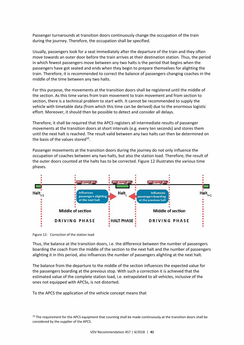
VDV Recommendation 457 | 4/2018 | 41
Passenger turnarounds at transition doors continuously change the occupation of the train during the journey. Therefore, the occupation shall be specified.
Usually, passengers look for a seat immediately after the departure of the train and they often move towards an outer door before the train arrives at their destination station. Thus, the period in which fewest passengers move between any two halts is the period that begins when the passengers have got seated and ends when they begin to prepare themselves for alighting the train. Therefore, it is recommended to correct the balance of passengers changing coaches in the middle of the time between any two halts.
For this purpose, the movements at the transition doors shall be registered until the middle of the section. As this time varies from train movement to train movement and from section to section, there is a technical problem to start with. It cannot be recommended to supply the vehicle with timetable data (from which this time can be derived) due to the enormous logistic effort. Moreover, it should then be possible to detect and consider all delays.
Therefore, it shall be required that the APCS registers all intermediate results of passenger movements at the transition doors at short intervals (e.g. every ten seconds) and stores them until the next halt is reached. The result valid between any two halts can then be determined on the basis of the values stored10.
Passenger movements at the transition doors during the journey do not only influence the occupation of coaches between any two halts, but also the station load. Therefore, the result of the outer doors counted at the halts has to be corrected. Figure 12 illustrates the various time phases.
Figure 12: Correction of the station load
Thus, the balance at the transition doors, i.e. the difference between the number of passengers boarding the coach from the middle of the section to the next halt and the number of passengers alighting it in this period, also influences the number of passengers alighting at the next halt.
The balance from the departure to the middle of the section influences the expected value for the passengers boarding at the previous stop. With such a correction it is achieved that the estimated value of the complete station load, i.e. extrapolated to all vehicles, inclusive of the ones not equipped with APCSs, is not distorted.
To the APCS the application of the vehicle concept means that
10 The requirement for the APCS equipment that counting shall be made continuously at the transition doors shall be considered by the supplier of the APCS.
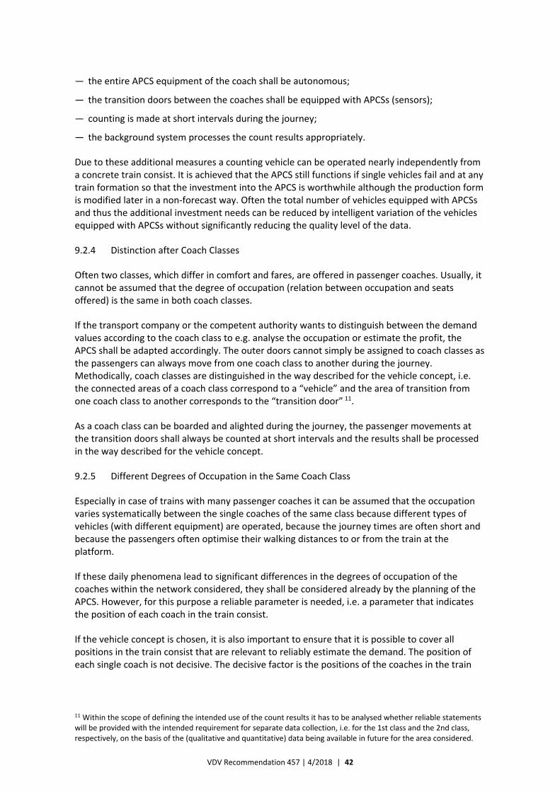
VDV Recommendation 457 | 4/2018 | 42
— the entire APCS equipment of the coach shall be autonomous;
— the transition doors between the coaches shall be equipped with APCSs (sensors);
— counting is made at short intervals during the journey;
— the background system processes the count results appropriately.
Due to these additional measures a counting vehicle can be operated nearly independently from a concrete train consist. It is achieved that the APCS still functions if single vehicles fail and at any train formation so that the investment into the APCS is worthwhile although the production form is modified later in a non‐forecast way. Often the total number of vehicles equipped with APCSs and thus the additional investment needs can be reduced by intelligent variation of the vehicles equipped with APCSs without significantly reducing the quality level of the data.
9.2.4 Distinction after Coach Classes
Often two classes, which differ in comfort and fares, are offered in passenger coaches. Usually, it cannot be assumed that the degree of occupation (relation between occupation and seats offered) is the same in both coach classes.
If the transport company or the competent authority wants to distinguish between the demand values according to the coach class to e.g. analyse the occupation or estimate the profit, the APCS shall be adapted accordingly. The outer doors cannot simply be assigned to coach classes as the passengers can always move from one coach class to another during the journey. Methodically, coach classes are distinguished in the way described for the vehicle concept, i.e. the connected areas of a coach class correspond to a “vehicle” and the area of transition from one coach class to another corresponds to the “transition door” 11.11F
As a coach class can be boarded and alighted during the journey, the passenger movements at the transition doors shall always be counted at short intervals and the results shall be processed in the way described for the vehicle concept.
9.2.5 Different Degrees of Occupation in the Same Coach Class
Especially in case of trains with many passenger coaches it can be assumed that the occupation varies systematically between the single coaches of the same class because different types of vehicles (with different equipment) are operated, because the journey times are often short and because the passengers often optimise their walking distances to or from the train at the platform.
If these daily phenomena lead to significant differences in the degrees of occupation of the coaches within the network considered, they shall be considered already by the planning of the APCS. However, for this purpose a reliable parameter is needed, i.e. a parameter that indicates the position of each coach in the train consist.
If the vehicle concept is chosen, it is also important to ensure that it is possible to cover all positions in the train consist that are relevant to reliably estimate the demand. The position of each single coach is not decisive. The decisive factor is the positions of the coaches in the train
11 Within the scope of defining the intended use of the count results it has to be analysed whether reliable statements will be provided with the intended requirement for separate data collection, i.e. for the 1st class and the 2nd class, respectively, on the basis of the (qualitative and quantitative) data being available in future for the area considered.
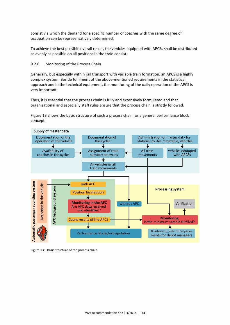
VDV Recommendation 457 | 4/2018 | 43
consist via which the demand for a specific number of coaches with the same degree of occupation can be representatively determined.
To achieve the best possible overall result, the vehicles equipped with APCSs shall be distributed as evenly as possible on all positions in the train consist.
9.2.6 Monitoring of the Process Chain
Generally, but especially within rail transport with variable train formation, an APCS is a highly complex system. Beside fulfilment of the above‐mentioned requirements in the statistical approach and in the technical equipment, the monitoring of the daily operation of the APCS is very important.
Thus, it is essential that the process chain is fully and extensively formulated and that organisational and especially staff rules ensure that the process chain is strictly followed.
Figure 13 shows the basic structure of such a process chain for a general performance block concept.
Figure 13: Basic structure of the process chain
VDV Recommendation 457 | 4/2018 | 44
10 Plausibility Checks and Corrections
It is a basic requirement that plausibility checks are made before count journeys are taken over and that non‐consistent count journeys, i.e. the resulting count data, are rejected.
Count journeys can be rejected e.g. if:
— they do not correspond to planned journeys;
— less than a parameterisable proportion of the halt locations (number of registered halt locations / number of planned halt locations) was registered (it should be noted that journeys with 0 passengers are not unusual at the beginning/end of the daily operation);
— their actual departure time at the first halt deviates more than a parameterisable interval from the planned departure time (above all within regional rail transport or if the interval between vehicles is ≥ 30 min; usually not applicable to urban transport);
— the actual times at the halts are not in ascending order;
— the maximum occupation of a route section during the journey clearly exceeds the vehicle capacity (adjustable parameter);
— the maximum journey‐time relation (actual journey time / planned journey time) exceeds a certain (adjustable) factor at a route element during the journey;
— neither boarding passengers nor alighting passengers are registered by (at least) one sensor in the complete period of registration (requirement for sensor‐exact message or detection);
— the difference in balance exceeds a certain adjustable set value (both a relative value and an absolute value are to be specified) or if the trains passing or the occupation are negative.
These requirements shall be specified in great detail in the specifications. This VDV Recommendation only includes facts that refer directly to statistical requirements. The exact specification shall be prepared by the transport company in consideration of its general conditions.
It shall always be possible to adjust the parameters. It should be possible for the software provider to specify certain parameters depending on the specific situation of the transport company/transport association (e.g. solutions for the transport association). The rejected journeys should be explicitly marked and displayed for check purposes.
The count data shall always be acquired in a reproducible way. It has to be ensured that all parameters that act directly on the generation of the count data are linked to them in a tamper‐proof way.
VDV Recommendation 457 | 4/2018 | 45
11 Extrapolation
11.1 Stratum‐bound Extrapolation from Sample
The mean number of persons transported per journey Pm is determined on the basis of a random sample by way of the sampling fraction c.
The extrapolation is made to the total number P of persons transported in the period of collection in accordance with the following equation:
(6)
i.e. by multiplication of the mean of passengers counted Pm by the number of journeys in the period of collection F(a) or by the corresponding quotient n / c. The sampling fraction c is the relation between the number of count journeys n and the number of journeys in the period of collection F(a).
If the sample is stratified, the extrapolation shall be made per stratum to begin with. Thereafter, the values of the single strata are added.
11.2 Extrapolation on the Basis of the Performance Block Procedure
11.1 specifies that the total of number of persons transported12 shall be extrapolated stratum for stratum from the product of the mean of passengers boarding per count journey and the number of course and train movements of the population. It is a condition for this approach that each count journey supplies data on all passengers boarding all vehicles equipped with APCSs at all halts.
As it has already been explained above, this assumption is not correct in case of the performance block procedure. In this case the train movement shall be divided into single vehicle movements, which are to be grouped to performance blocks (identical train formation). Thus, the timetable, i.e. the sum of all journeys, cannot be the only kind of information about the population of the offer. To estimate the expected total demand for transport on the basis of the count results of the single vehicles on the single sections of movement, it has to be known which vehicles were actually operated. Usually, such information is known anyway for other reasons.
If this nomenclature is extended by analogy,
P = i
imi aWP )( (7)
12 As in all pure countings the term “persons transported” mean the number of passengers transported per line or per train. It is assumed that a passenger on a line/train does not change trains. In this case this variable corresponds to the number of passengers boarding.
cnPaFPP mm )(
VDV Recommendation 457 | 4/2018 | 46
applies,
where
i is the section of movement;
Wi(a) is the number of vehicles operated in this section in the period of collection;
Pmi is the mean of the counted passengers boarding per journey of the vehicle in section i.
Here, too, the information shall also be provided for each stratum. If necessary, coaches of the same class or vehicles with the same degree of occupation shall also be considered.
It is obvious that this basic structure leads to systematic underestimation of the population if no further action is taken, i.e. if the actual count values (Pmi) are not available for all combinations of sections and strata. Although the process of monitoring count journeys can reduce this risk, e.g. by purposive selection of count journeys, it cannot be excluded that this case occurs in practical applications, particularly in case of short periods of collection. Therefore, the extrapolation procedure shall include suitable measures (e.g. clustering of sections or imputation procedure).
Beside the mere registration of the number of passengers transported per stratum13 estimated values are needed for
— passengers boarding per halt;
— passengers alighting per halt;
— occupation / transport performance per section,
for any combination of train number and weekday group, especially in case of rail transport. However, it is only possible to successfully determine such estimated values if consistency conditions have also been fulfilled in respect of content by the count data for the previous occupation, passengers boarding and alighting and the subsequent occupation. They are fulfilled by way of the correction and balancing procedure described in chapter 8 for each single vehicle, but not if performance blocks of a train movement are connected over several days of collection 4F
14. In this case it shall be assumed that the demand for transport varies at random and that the consistency conditions are offended against for halts with changing performance blocks. The count results shall then be logically balanced before the extrapolation.
Thus, it shall be decided which parameter, i.e. transport volume (passengers boarding and alighting) or transport performance, shall be taken over from the count data and which parameter shall be adapted. Rules for prevention of systematic distortion of the results shall be agreed upon.
Finally, characteristic features of the variable train formation are that the seat offer varies during the train movement and that vehicles also change train numbers with passengers on‐board (branching and interconnection). This means that a train movement can get or lose passengers at a station without physical passengers boarding or alighting and thus being counted at the outer doors by the APC devices.
13 Often a stratum is a combination of line, daytime slots and weekday groups or (within rail transport) of train number and weekday groups.
14 of the identical stratum.
VDV Recommendation 457 | 4/2018 | 47
11.3 Extrapolation on the Basis of the Vehicle Concept
It is a condition for the vehicle concept, according to which some vehicles of a counting train are equipped with APCSs and passengers can move from passenger coach to passenger coach via transition doors, also during the journey, that the performance block procedure is applied. All adaptations and requirements also apply to the vehicle concept.
In addition, the balance between passenger movements through the transition doors shall be considered in the vehicle concept as it influences both the occupation for a section of movement and the station load for the stops. The reference point for the occupation on a section of movement is the mean of time between the beginning and the end of the section, i.e. distinction shall be made between two balance values following one another in the driving phase.
Moreover, the passengers who are counted at the outer doors as boarding and alighting at the halt shall be separately corrected by way of transition door balances before the halt, at the halt and after the halt. In this way a positive balance at the transition doors during the halt phase increases the number of passengers boarding, whereas a negative balance increases the number of passengers alighting.
Practically, the passenger movement before the halt station is similar to the alighting behaviour (e.g. preparation for alighting, early leaving of the passenger coach). The passenger movement after the halt station is rather similar to the boarding behaviour (e.g. looking for a seat). Consequently,
— the passenger movement through the transition doors during the driving phase shall be considered separately for the section before the halt station (2nd half) and the section after the halt station (1st half) in the form of separate balances;
— the balance before the halt station mainly adapts the number of passengers alighting (a positive balance reduces the number of passengers alighting; a negative balance increases this number);
— the balance after the halt station mainly adapts the number of passengers boarding (a positive balance increases the number of passengers boarding; a negative balance reduces this number).
Thus, it is not the objective to make small corrections in the numbers for the driving phase, but to adapt them in accordance with the different functions of the section before the halt station and the section after the halt station, respectively. Upwards and downwards adaptation of the station load as a function of the plus/minus signs of the balances prevents overestimation of the station load on average.
The restriction in the form of the term “mainly” in the second and third bullets is made because adaptation is not always possible if a balance exceeds the number of passengers boarding or alighting at the outer doors.

VDV Recommendation 457 | 4/2018 | 48
Annex A: Check List for the Quality Management concerning the Operation of the APCS
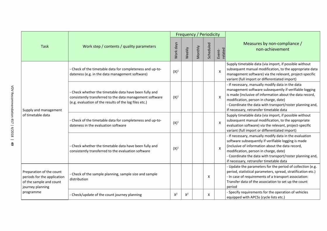
VDV Reco
mmen
datio
n 457 | 4
/2018 |
49
Task Work step / contents / quality parameters
Frequency / Periodicity
Measures by non‐compliance / non‐achievement
Work days
Wee
kly
Monthly
Sched
uled
Even
t‐
related
Supply and management
of timetable data
‐ Check of the timetable data for completeness and up‐to‐
dateness (e.g. in the data management software) (X)1 X
Supply timetable data (via import, if possible without
subsequent manual modification, to the appropriate data
management software) via the relevant, project‐specific
variant (full import or differentiated import)
‐ Check whether the timetable data have been fully and
consistently transferred to the data management software
(e.g. evaluation of the results of the log files etc.)
(X)1 X
‐ If necessary, manually modify data in the data
management software subsequently if verifiable logging
is made (inclusive of information about the data record,
modification, person in charge, date)
‐ Coordinate the data with transport/roster planning and,
if necessary, retransfer timetable data
‐ Check of the timetable data for completeness and up‐to‐
dateness in the evaluation software (X)1 X
Supply timetable data (via import, if possible without
subsequent manual modification, to the appropriate
evaluation software) via the relevant, project‐specific
variant (full import or differentiated import)
‐ Check whether the timetable data have been fully and
consistently transferred to the evaluation software (X)1 X
‐ If necessary, manually modify data in the evaluation
software subsequently if verifiable logging is made
(inclusive of information about the data record,
modification, person in charge, date)
‐ Coordinate the data with transport/roster planning and,
if necessary, retransfer timetable data
Preparation of the count
periods for the application
of the sample and count
journey planning
programme
‐ Check of the sample planning, sample size and sample
distribution X
‐ Update the parameters for the period of collection (e.g.
period, statistical parameters, spread, stratification etc.)
‐ In case of requirements of a transport association:
Transfer data of the association to set up the count
period
‐ Check/update of the count journey planning X2 X2 X ‐ Specify requirements for the operation of vehicles
equipped with APCSs (cycle lists etc.)
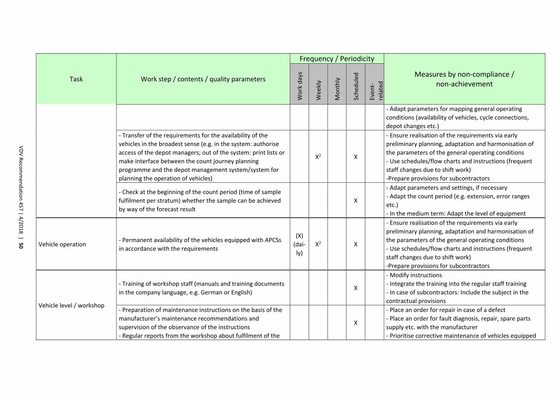
VDV Reco
mmen
datio
n 457 | 4
/2018 |
50
Task Work step / contents / quality parameters
Frequency / Periodicity
Measures by non‐compliance / non‐achievement
Work days
Wee
kly
Monthly
Sched
uled
Even
t‐
related
‐ Adapt parameters for mapping general operating
conditions (availability of vehicles, cycle connections,
depot changes etc.)
‐ Transfer of the requirements for the availability of the
vehicles in the broadest sense (e.g. in the system: authorise
access of the depot managers; out of the system: print lists or
make interface between the count journey planning
programme and the depot management system/system for
planning the operation of vehicles)
X2 X
‐ Ensure realisation of the requirements via early
preliminary planning, adaptation and harmonisation of
the parameters of the general operating conditions
‐ Use schedules/flow charts and instructions (frequent
staff changes due to shift work)
‐Prepare provisions for subcontractors
‐ Check at the beginning of the count period (time of sample
fulfilment per stratum) whether the sample can be achieved
by way of the forecast result
X
‐ Adapt parameters and settings, if necessary
‐ Adapt the count period (e.g. extension, error ranges
etc.)
‐ In the medium term: Adapt the level of equipment
Vehicle operation ‐ Permanent availability of the vehicles equipped with APCSs
in accordance with the requirements
(X)
(dai‐
ly)
X2 X
‐ Ensure realisation of the requirements via early
preliminary planning, adaptation and harmonisation of
the parameters of the general operating conditions
‐ Use schedules/flow charts and instructions (frequent
staff changes due to shift work)
‐Prepare provisions for subcontractors
Vehicle level / workshop
‐ Training of workshop staff (manuals and training documents
in the company language, e.g. German or English) X
‐ Modify instructions
‐ Integrate the training into the regular staff training
‐ In case of subcontractors: Include the subject in the
contractual provisions
‐ Preparation of maintenance instructions on the basis of the
manufacturer’s maintenance recommendations and
supervision of the observance of the instructions
‐ Regular reports from the workshop about fulfilment of the
X
‐ Place an order for repair in case of a defect
‐ Place an order for fault diagnosis, repair, spare parts
supply etc. with the manufacturer
‐ Prioritise corrective maintenance of vehicles equipped
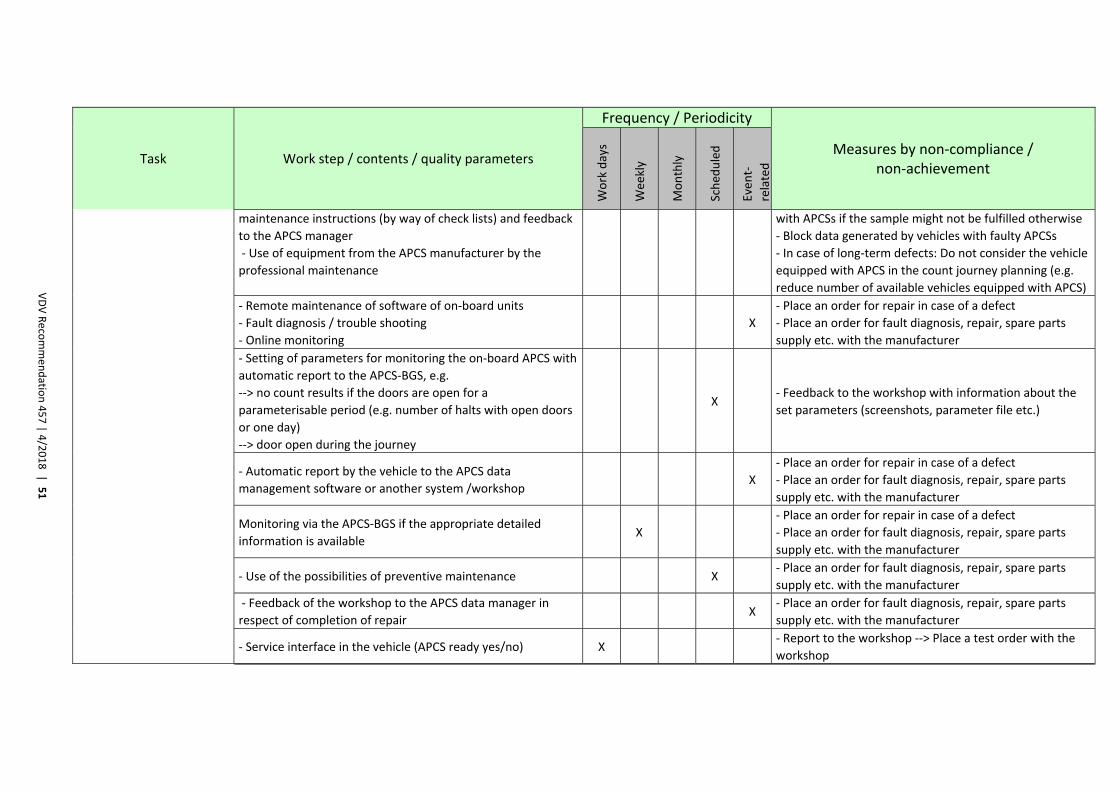
VDV Reco
mmen
datio
n 457 | 4
/2018 |
51
Task Work step / contents / quality parameters
Frequency / Periodicity
Measures by non‐compliance / non‐achievement
Work days
Wee
kly
Monthly
Sched
uled
Even
t‐
related
maintenance instructions (by way of check lists) and feedback
to the APCS manager
‐ Use of equipment from the APCS manufacturer by the
professional maintenance
with APCSs if the sample might not be fulfilled otherwise
‐ Block data generated by vehicles with faulty APCSs
‐ In case of long‐term defects: Do not consider the vehicle
equipped with APCS in the count journey planning (e.g.
reduce number of available vehicles equipped with APCS)
‐ Remote maintenance of software of on‐board units
‐ Fault diagnosis / trouble shooting
‐ Online monitoring
X
‐ Place an order for repair in case of a defect
‐ Place an order for fault diagnosis, repair, spare parts
supply etc. with the manufacturer
‐ Setting of parameters for monitoring the on‐board APCS with
automatic report to the APCS‐BGS, e.g.
‐‐> no count results if the doors are open for a
parameterisable period (e.g. number of halts with open doors
or one day)
‐‐> door open during the journey
X ‐ Feedback to the workshop with information about the
set parameters (screenshots, parameter file etc.)
‐ Automatic report by the vehicle to the APCS data
management software or another system /workshop X
‐ Place an order for repair in case of a defect
‐ Place an order for fault diagnosis, repair, spare parts
supply etc. with the manufacturer
Monitoring via the APCS‐BGS if the appropriate detailed
information is available X
‐ Place an order for repair in case of a defect
‐ Place an order for fault diagnosis, repair, spare parts
supply etc. with the manufacturer
‐ Use of the possibilities of preventive maintenance X ‐ Place an order for fault diagnosis, repair, spare parts
supply etc. with the manufacturer
‐ Feedback of the workshop to the APCS data manager in
respect of completion of repair X
‐ Place an order for fault diagnosis, repair, spare parts
supply etc. with the manufacturer
‐ Service interface in the vehicle (APCS ready yes/no) X ‐ Report to the workshop ‐‐> Place a test order with the
workshop
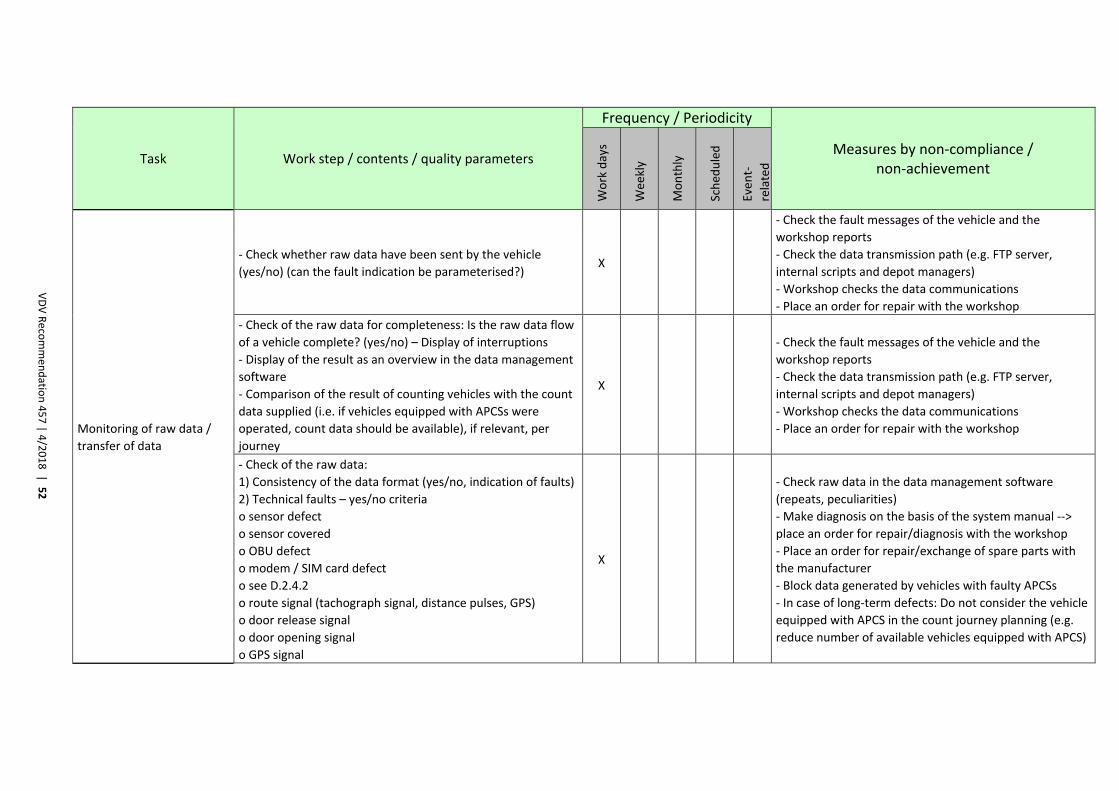
VDV Reco
mmen
datio
n 457 | 4
/2018 |
52
Task Work step / contents / quality parameters
Frequency / Periodicity
Measures by non‐compliance / non‐achievement
Work days
Wee
kly
Monthly
Sched
uled
Even
t‐
related
Monitoring of raw data /
transfer of data
‐ Check whether raw data have been sent by the vehicle
(yes/no) (can the fault indication be parameterised?) X
‐ Check the fault messages of the vehicle and the
workshop reports
‐ Check the data transmission path (e.g. FTP server,
internal scripts and depot managers)
‐ Workshop checks the data communications
‐ Place an order for repair with the workshop
‐ Check of the raw data for completeness: Is the raw data flow
of a vehicle complete? (yes/no) – Display of interruptions
‐ Display of the result as an overview in the data management
software
‐ Comparison of the result of counting vehicles with the count
data supplied (i.e. if vehicles equipped with APCSs were
operated, count data should be available), if relevant, per
journey
X
‐ Check the fault messages of the vehicle and the
workshop reports
‐ Check the data transmission path (e.g. FTP server,
internal scripts and depot managers)
‐ Workshop checks the data communications
‐ Place an order for repair with the workshop
‐ Check of the raw data:
1) Consistency of the data format (yes/no, indication of faults)
2) Technical faults – yes/no criteria
o sensor defect
o sensor covered
o OBU defect
o modem / SIM card defect
o see D.2.4.2
o route signal (tachograph signal, distance pulses, GPS)
o door release signal
o door opening signal
o GPS signal
X
‐ Check raw data in the data management software
(repeats, peculiarities)
‐ Make diagnosis on the basis of the system manual ‐‐>
place an order for repair/diagnosis with the workshop
‐ Place an order for repair/exchange of spare parts with
the manufacturer
‐ Block data generated by vehicles with faulty APCSs
‐ In case of long‐term defects: Do not consider the vehicle
equipped with APCS in the count journey planning (e.g.
reduce number of available vehicles equipped with APCS)
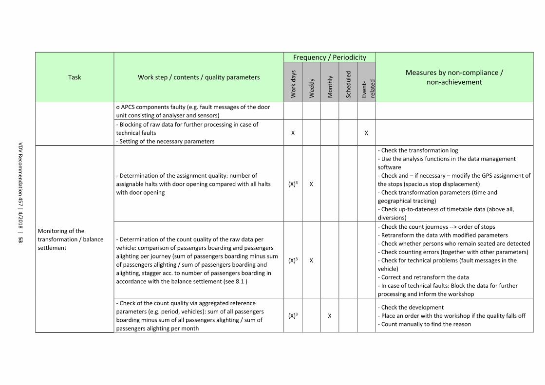
VDV Reco
mmen
datio
n 457 | 4
/2018 |
53
Task Work step / contents / quality parameters
Frequency / Periodicity
Measures by non‐compliance / non‐achievement
Work days
Wee
kly
Monthly
Sched
uled
Even
t‐
related
o APCS components faulty (e.g. fault messages of the door
unit consisting of analyser and sensors)
‐ Blocking of raw data for further processing in case of
technical faults
‐ Setting of the necessary parameters
X X
Monitoring of the
transformation / balance
settlement
‐ Determination of the assignment quality: number of
assignable halts with door opening compared with all halts
with door opening
(X)3 X
‐ Check the transformation log
‐ Use the analysis functions in the data management
software
‐ Check and – if necessary – modify the GPS assignment of
the stops (spacious stop displacement)
‐ Check transformation parameters (time and
geographical tracking)
‐ Check up‐to‐dateness of timetable data (above all,
diversions)
‐ Determination of the count quality of the raw data per
vehicle: comparison of passengers boarding and passengers
alighting per journey (sum of passengers boarding minus sum
of passengers alighting / sum of passengers boarding and
alighting, stagger acc. to number of passengers boarding in
accordance with the balance settlement (see 8.1 )
(X)3 X
‐ Check the count journeys ‐‐> order of stops
‐ Retransform the data with modified parameters
‐ Check whether persons who remain seated are detected
‐ Check counting errors (together with other parameters)
‐ Check for technical problems (fault messages in the
vehicle)
‐ Correct and retransform the data
‐ In case of technical faults: Block the data for further
processing and inform the workshop
‐ Check of the count quality via aggregated reference
parameters (e.g. period, vehicles): sum of all passengers
boarding minus sum of all passengers alighting / sum of
passengers alighting per month
(X)3 X ‐ Check the development
‐ Place an order with the workshop if the quality falls off
‐ Count manually to find the reason
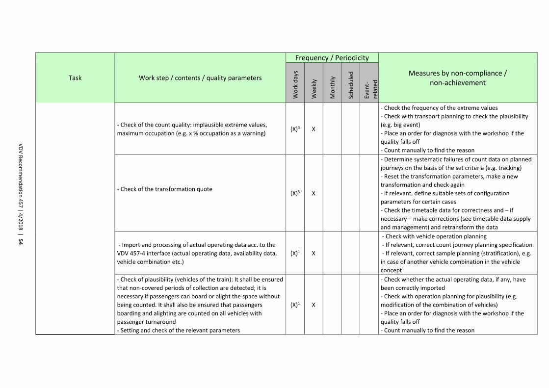
VDV Reco
mmen
datio
n 457 | 4
/2018 |
54
Task Work step / contents / quality parameters
Frequency / Periodicity
Measures by non‐compliance / non‐achievement
Work days
Wee
kly
Monthly
Sched
uled
Even
t‐
related
‐ Check of the count quality: implausible extreme values,
maximum occupation (e.g. x % occupation as a warning) (X)3 X
‐ Check the frequency of the extreme values
‐ Check with transport planning to check the plausibility
(e.g. big event)
‐ Place an order for diagnosis with the workshop if the
quality falls off
‐ Count manually to find the reason
‐ Check of the transformation quote
(X)3 X
‐ Determine systematic failures of count data on planned
journeys on the basis of the set criteria (e.g. tracking)
‐ Reset the transformation parameters, make a new
transformation and check again
‐ If relevant, define suitable sets of configuration
parameters for certain cases
‐ Check the timetable data for correctness and – if
necessary – make corrections (see timetable data supply
and management) and retransform the data
‐ Import and processing of actual operating data acc. to the
VDV 457‐4 interface (actual operating data, availability data,
vehicle combination etc.)
(X)1 X
‐ Check with vehicle operation planning
‐ If relevant, correct count journey planning specification
‐ If relevant, correct sample planning (stratification), e.g.
in case of another vehicle combination in the vehicle
concept
‐ Check of plausibility (vehicles of the train): It shall be ensured
that non‐covered periods of collection are detected; it is
necessary if passengers can board or alight the space without
being counted. It shall also be ensured that passengers
boarding and alighting are counted on all vehicles with
passenger turnaround
‐ Setting and check of the relevant parameters
(X)1 X
‐ Check whether the actual operating data, if any, have
been correctly imported
‐ Check with operation planning for plausibility (e.g.
modification of the combination of vehicles)
‐ Place an order for diagnosis with the workshop if the
quality falls off
‐ Count manually to find the reason
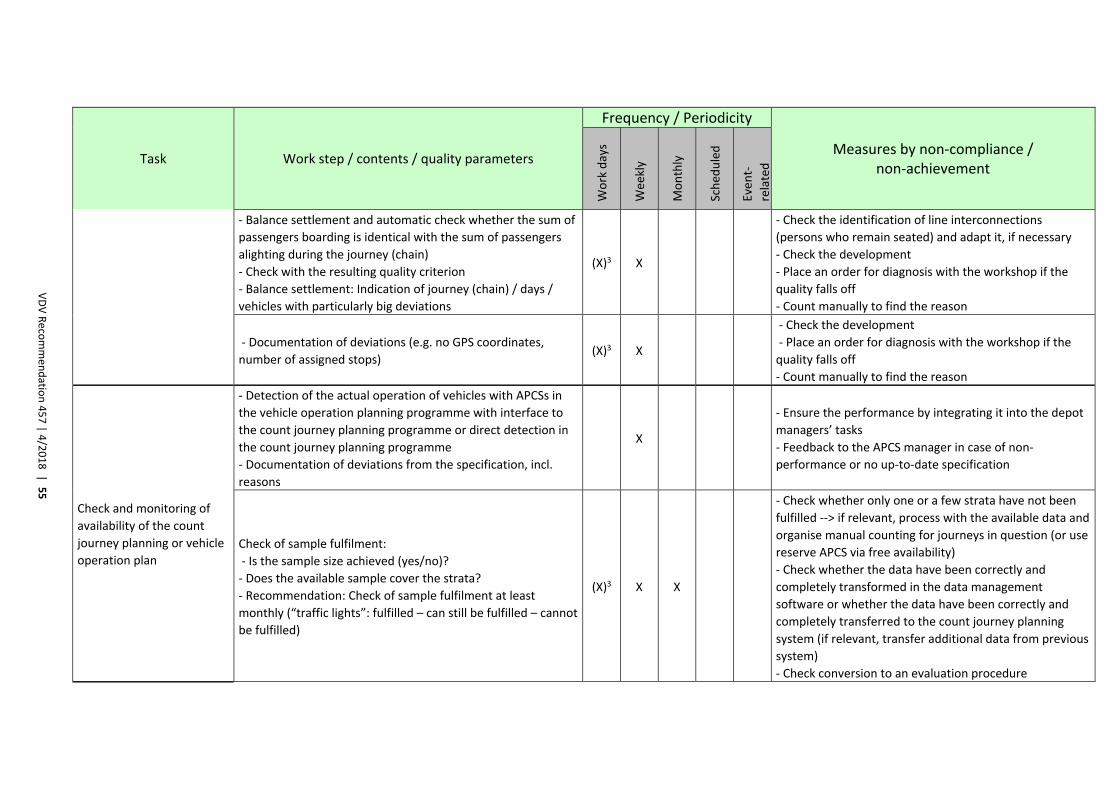
VDV Reco
mmen
datio
n 457 | 4
/2018 |
55
Task Work step / contents / quality parameters
Frequency / Periodicity
Measures by non‐compliance / non‐achievement
Work days
Wee
kly
Monthly
Sched
uled
Even
t‐
related
‐ Balance settlement and automatic check whether the sum of
passengers boarding is identical with the sum of passengers
alighting during the journey (chain)
‐ Check with the resulting quality criterion
‐ Balance settlement: Indication of journey (chain) / days /
vehicles with particularly big deviations
(X)3 X
‐ Check the identification of line interconnections
(persons who remain seated) and adapt it, if necessary
‐ Check the development
‐ Place an order for diagnosis with the workshop if the
quality falls off
‐ Count manually to find the reason
‐ Documentation of deviations (e.g. no GPS coordinates,
number of assigned stops) (X)3 X
‐ Check the development
‐ Place an order for diagnosis with the workshop if the
quality falls off
‐ Count manually to find the reason
Check and monitoring of
availability of the count
journey planning or vehicle
operation plan
‐ Detection of the actual operation of vehicles with APCSs in
the vehicle operation planning programme with interface to
the count journey planning programme or direct detection in
the count journey planning programme
‐ Documentation of deviations from the specification, incl.
reasons
X
‐ Ensure the performance by integrating it into the depot
managers’ tasks
‐ Feedback to the APCS manager in case of non‐
performance or no up‐to‐date specification
Check of sample fulfilment:
‐ Is the sample size achieved (yes/no)?
‐ Does the available sample cover the strata?
‐ Recommendation: Check of sample fulfilment at least
monthly (“traffic lights”: fulfilled – can still be fulfilled – cannot
be fulfilled)
(X)3 X X
‐ Check whether only one or a few strata have not been
fulfilled ‐‐> if relevant, process with the available data and
organise manual counting for journeys in question (or use
reserve APCS via free availability)
‐ Check whether the data have been correctly and
completely transformed in the data management
software or whether the data have been correctly and
completely transferred to the count journey planning
system (if relevant, transfer additional data from previous
system)
‐ Check conversion to an evaluation procedure
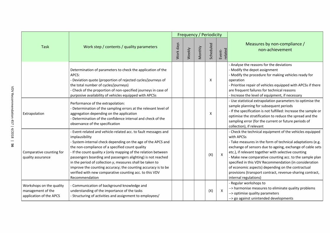
VDV Reco
mmen
datio
n 457 | 4
/2018 |
56
Task Work step / contents / quality parameters
Frequency / Periodicity
Measures by non‐compliance / non‐achievement
Work days
Wee
kly
Monthly
Sched
uled
Even
t‐
related
Determination of parameters to check the application of the
APCS:
‐ Deviation quote (proportion of rejected cycles/journeys of
the total number of cycles/journeys)
‐ Check of the proportion of non‐specified journeys in case of
purposive availability of vehicles equipped with APCSs
X
‐ Analyse the reasons for the deviations
‐ Modify the depot assignment
‐ Modify the procedure for making vehicles ready for
operation
‐ Prioritise repair of vehicles equipped with APCSs if there
are frequent failures for technical reasons
‐ Increase the level of equipment, if necessary
Extrapolation
Performance of the extrapolation:
‐ Determination of the sampling errors at the relevant level of
aggregation depending on the application
‐ Determination of the confidence interval and check of the
observance of the specification
X
‐ Use statistical extrapolation parameters to optimise the
sample planning for subsequent periods
‐ If the specification is not fulfilled: Increase the sample or
optimise the stratification to reduce the spread and the
sampling error (for the current or future periods of
collection), if relevant
Comparative counting for
quality assurance
‐ Event‐related and vehicle‐related acc. to fault messages and
implausibility
‐ System‐internal check depending on the age of the APCS and
the non‐compliance of a specified count quality
‐ If the count quality x (only mapping of the relation between
passengers boarding and passengers alighting) is not reached
in the period of collection y, measures shall be taken to
improve the counting accuracy; the counting accuracy is to be
verified with new comparative counting acc. to this VDV
Recommendation
(X) X
‐ Check the technical equipment of the vehicles equipped
with APCSs
‐ Take measures in the form of technical adaptations (e.g.
exchange of sensors due to ageing, exchange of cable sets
etc.), if relevant together with selective counting
‐ Make new comparative counting acc. to the sample plan
specified in this VDV Recommendation (in consideration
of economic aspects) depending on the contractual
provisions (transport contract, revenue‐sharing contract,
internal regulations)
Workshops on the quality
management of the
application of the APCS
‐ Communication of background knowledge and
understanding of the importance of the tasks
‐ Structuring of activities and assignment to employees/
(X) X
‐ Regular workshops to
‐‐> harmonise measures to eliminate quality problems
‐‐> optimise quality parameters
‐‐> go against unintended developments
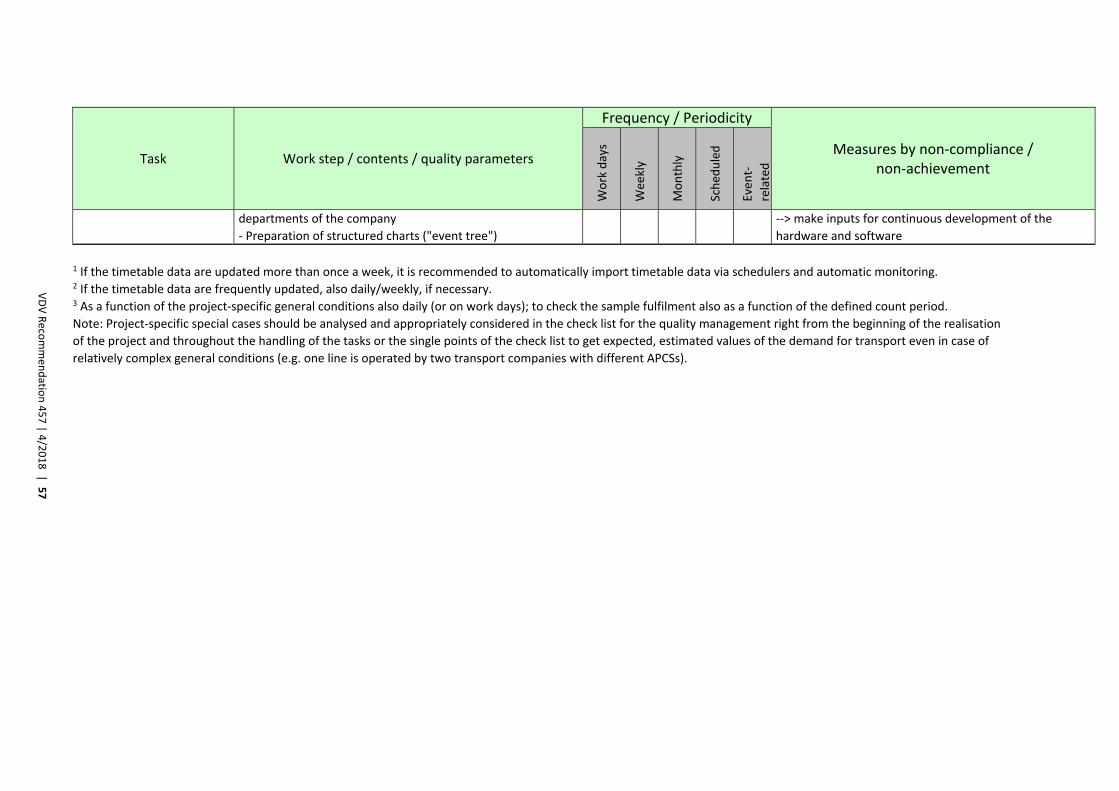
VDV Reco
mmen
datio
n 457 | 4
/2018 |
57
Task Work step / contents / quality parameters
Frequency / Periodicity
Measures by non‐compliance / non‐achievement
Work days
Wee
kly
Monthly
Sched
uled
Even
t‐
related
departments of the company
‐ Preparation of structured charts ("event tree")
‐‐> make inputs for continuous development of the
hardware and software
1 If the timetable data are updated more than once a week, it is recommended to automatically import timetable data via schedulers and automatic monitoring. 2 If the timetable data are frequently updated, also daily/weekly, if necessary. 3 As a function of the project‐specific general conditions also daily (or on work days); to check the sample fulfilment also as a function of the defined count period.
Note: Project‐specific special cases should be analysed and appropriately considered in the check list for the quality management right from the beginning of the realisation
of the project and throughout the handling of the tasks or the single points of the check list to get expected, estimated values of the demand for transport even in case of
relatively complex general conditions (e.g. one line is operated by two transport companies with different APCSs).
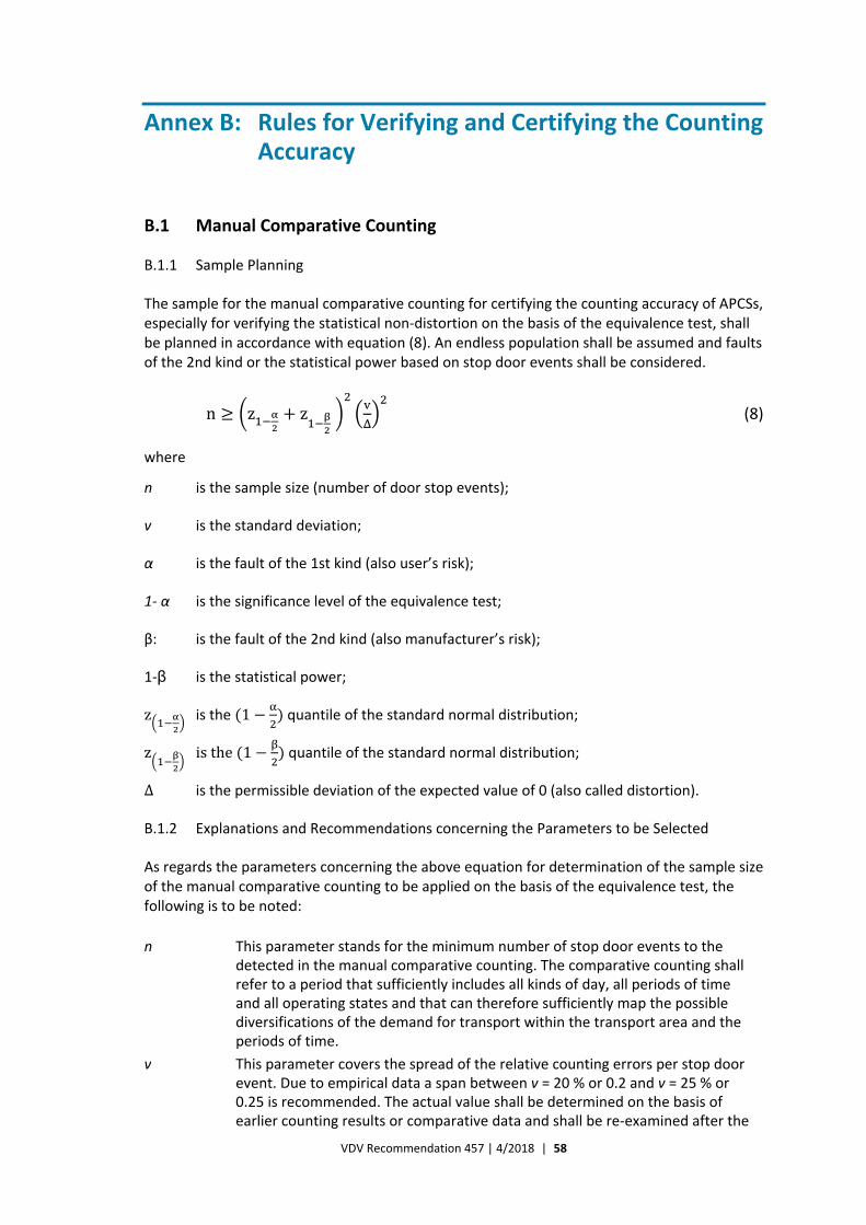
VDV Recommendation 457 | 4/2018 | 58
Annex B: Rules for Verifying and Certifying the Counting Accuracy
B.1 Manual Comparative Counting
B.1.1 Sample Planning
The sample for the manual comparative counting for certifying the counting accuracy of APCSs, especially for verifying the statistical non‐distortion on the basis of the equivalence test, shall be planned in accordance with equation (8). An endless population shall be assumed and faults of the 2nd kind or the statistical power based on stop door events shall be considered.
n z z (8)
where
n is the sample size (number of door stop events);
v is the standard deviation;
α is the fault of the 1st kind (also user’s risk);
1‐ α is the significance level of the equivalence test;
β: is the fault of the 2nd kind (also manufacturer’s risk);
1‐β is the statistical power;
z is the 1 quantile of the standard normal distribution;
z isthe 1 quantile of the standard normal distribution;
Δ is the permissible deviation of the expected value of 0 (also called distortion).
B.1.2 Explanations and Recommendations concerning the Parameters to be Selected
As regards the parameters concerning the above equation for determination of the sample size of the manual comparative counting to be applied on the basis of the equivalence test, the following is to be noted:
n This parameter stands for the minimum number of stop door events to the detected in the manual comparative counting. The comparative counting shall refer to a period that sufficiently includes all kinds of day, all periods of time and all operating states and that can therefore sufficiently map the possible diversifications of the demand for transport within the transport area and the periods of time.
v This parameter covers the spread of the relative counting errors per stop door event. Due to empirical data a span between v = 20 % or 0.2 and v = 25 % or 0.25 is recommended. The actual value shall be determined on the basis of earlier counting results or comparative data and shall be re‐examined after the
VDV Recommendation 457 | 4/2018 | 59
evaluation. In the calls for tenders the manufacturers should be requested to provide empirically validated values for v for the planning of the sample for the comparative counting.
α It should be assumed that faults of the 1st kind (user’s risk in case of the equivalence test) amounts to α = 5 % or 0.05.
1‐ α This parameter indicates the probability of non‐occurrence of a fault of the 1st kind. If α = 5 % or 0.05, it amounts to 0.95.
β It should be assumed that faults of the 2nd kind (manufacturer’s risk in case of the equivalence test) amounts to β = 5 % or 0.05.
1‐β This parameter indicates the statistical power, i.e. the probability of non‐occurrence of a fault of the 2nd kind. If β = 5 % or 0.05, it amounts to 0.95.
z This value can be found in many tables, e.g.: Table 5.6 (page 262) in “Angewandte Statistik: Methodensammlung mit R” (en: Applied Statistics: Methods with R), which has been written by Hedderich & Sachs and published by Springer‐Verlag GmbH in 2016. If α = 5 %, a value of 1.959960 or – rounded off – 1.96 results for the 97.5 % quantile of the standard normal distribution.
z This value can be found in many tables, e.g.: Table 5.6 (page 262) in “Angewandte Statistik: Methodensammlung mit R” (en: Applied Statistics: Methods with R), which has been written by Hedderich & Sachs and published by Springer‐Verlag GmbH in 2016. If β = 5 %, a value of 1.959960 or – rounded off – 1.96 results for the 97.5 % quantile of the standard normal distribution.
Δ This parameter represents the maximum permissible deviation (distortion) in the equivalence test. This value should be defined and specified to a span between 0.01 and 0.02 depending on the mode of transport. It is recommended to set ∆ = 0.01 as the maximum permissible deviation (distortion) in the equivalence test if the APCS data are to be used for the revenue sharing by transport associations. Moreover, competent authorities should define standard values for all modes of transport in calls for tenders concerning the transport performance; these values should not exceed 0.02.
It is recommended to increase the sample size needed for statistical purposes (number of stop door events) for the manual comparative counting for the certification of the counting accuracy by about 15 % depending on the specific conditions in the period of interest. In this way the effect of halts without passenger turnaround and the effect of losses are compensated if data collected automatically are not available for all boarding and alighting passengers counted manually for the comparative calculation, e.g. because data records have been eliminated. It is recommended to collect data on the number of stop door events without passenger turnaround in the form of either comparative data or small pilot samples and to consider them by the planning of the comparative counting. It is also recommended to limit the proportion of stop door events without passenger turnaround to maximum 10 %. The relevant preliminary analyses or assumptions are to be documented and included in the documentation of the certification of the counting accuracy. If the result indicates that the extended sample will not be fulfilled either, it can be necessary to adapt the given values.
B.1.3 Example of Sample Planning
The sample size n amounts to 6,147 stop door events to be collected on this statistical‐mathematical basis if the following parameters are applied in equation (8):
α 5 % or 0.05
β 5 % or 0.05
VDV Recommendation 457 | 4/2018 | 60
α 5 % or 0.05
v 0.2
∆ 001
z 1.96
z 196
B.2 Counting Accuracy
B.2.1 Verification Level, Parameters and Requirements
For practical reasons it is recommended to use the vehicle categories as the verification level. They shall be so defined in respect of the types of vehicle and the types of door that all vehicle categories are detected proportionally during the comparative counting.
If desired, the verification level can also be the transport company. In this case it has to be ensured that all vehicle categories are detected at the transport company verification level during the comparative counting. Transport associations shall specify the reference to the verification level to ensure that the accuracies of the count results are comparable. This is particularly important if count data are applied for the revenue sharing.
To observe the counting accuracy of the APCS in respect of the “transport volume” (P) parameter and the “transport performance” (Pkm) parameter, the following barriers have to be observed at the relevant verification level:
a) the differences in the sums of the automatic count values of passengers boarding and alighting at all halts during all count journeys shall not exceed 1 % of the manual count values per verification level (verification of the global non‐distortion);
b) ≤ 5 % of all door stop events shall be faulty; a door stop event is faulty if it deviates more than one third [33.3 %] from the value counted manually and if it also deviates by more than one person (verification of a single deviation); or
c) ≤ 5 % of all halts shall be faulty; a single result of all doors of a counting vehicle at a halt is regarded as faulty if it deviates more than 20 % from the value counted manually and if it also deviates by more than one person;
d) the statistical test of the statistical non‐distortion shall be performed on the basis of the equivalence test (verification of the statistical non‐distortion).
B.2.1.1 Supplementary Specification of the Transport Volume (P)
In justified, exceptional cases, i.e. depending on the intended application of the count data, the customer can deviate from the requirement given in barrier a) if the total error resulting from the sum of the sampling error for the statistical mean value dr based on a significance level of 95 % or 0.95 and the random counting error does not exceed 5 %. A sampling error is the maximum permissible sampling error for the statistical mean value dr that can be realised by an APCS on the basis of actual level of equipment and the sample size to be realised at all times with this equipment (number of count journeys) in proportion to the population.
VDV Recommendation 457 | 4/2018 | 61
However, the implied bigger error interval for the counting accuracy according to barrier a) does not reduce the requirement for the counting accuracy of the APCS in the vehicles. The requirement for counting accuracy of the APCS in the vehicles, which is specified in barrier a), still applies. The bigger error interval for the counting accuracy exclusively applies to the count data after the balance settlement in the APCS‐BGS.
It is allowed to combine these requirements for observance of the counting accuracy with minimum requirements for frequency classes of passengers boarding and alighting if they are justified from a mathematical‐statistical point of view and if their basis is disclosed.
To certify the counting accuracy at the halt or door halt level either barrier b) or barrier c) shall be applied.
B.2.1.2 Supplementary Specification of the Transport Performance (Pkm
The counting accuracy of the APCS in respect of the “transport performance” (Pkm) parameter is determined on the basis of the occupation between any two stops, which is in turn determined on the basis of the number of passengers boarding and the number of passengers alighting and via multiplication of the occupation with the distance between these two stops after having applied the algorithm for balance settlement described in 8.1.
Thus, the counting accuracy of the transport performance parameter can only be confirmed at this level. Reference is also made to Annex C, especially to C.2.2.4.
B.2.1.3 Special Cases
By the verification for the determination of the counting accuracy it has to be ensured at the state of the art that special cases are detected, considered and evaluated in such a way that a non‐distorted result can be mapped on the basis of the persons counted.
Therefore, the verification for the determination of the counting accuracy shall consider cases often occurring within public transport or comparable special cases, e.g.:
— persons standing in the doors;
— rucksacks;
— dogs;
— big pieces of luggage;
— bicycles;
— walking frames;
— prams;
— wheelchairs (differentiation between wheelchairs with seated persons and wheelchairs without seated persons, if relevant);
— wheelchair lift,
and compensate for these cases without distorting the total number of passengers boarding and alighting. Thus, these special cases shall not be counted as passengers boarding or alighting, but they shall be detected, logged and included in the evaluation to explain deviations from the comparative counting.
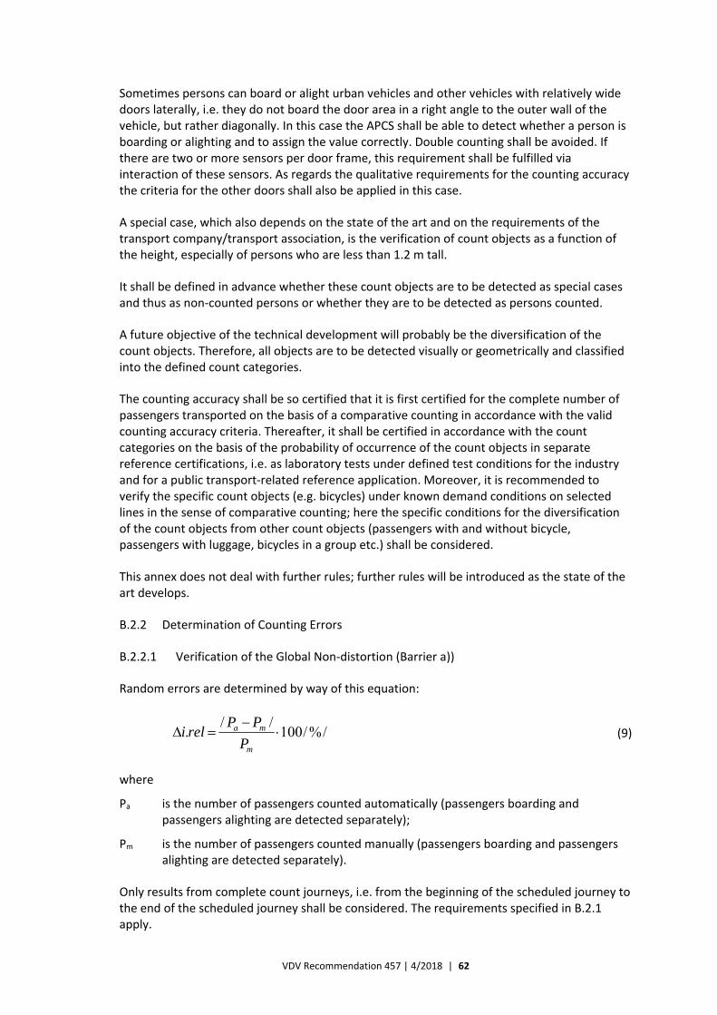
VDV Recommendation 457 | 4/2018 | 62
Sometimes persons can board or alight urban vehicles and other vehicles with relatively wide doors laterally, i.e. they do not board the door area in a right angle to the outer wall of the vehicle, but rather diagonally. In this case the APCS shall be able to detect whether a person is boarding or alighting and to assign the value correctly. Double counting shall be avoided. If there are two or more sensors per door frame, this requirement shall be fulfilled via interaction of these sensors. As regards the qualitative requirements for the counting accuracy the criteria for the other doors shall also be applied in this case.
A special case, which also depends on the state of the art and on the requirements of the transport company/transport association, is the verification of count objects as a function of the height, especially of persons who are less than 1.2 m tall.
It shall be defined in advance whether these count objects are to be detected as special cases and thus as non‐counted persons or whether they are to be detected as persons counted.
A future objective of the technical development will probably be the diversification of the count objects. Therefore, all objects are to be detected visually or geometrically and classified into the defined count categories.
The counting accuracy shall be so certified that it is first certified for the complete number of passengers transported on the basis of a comparative counting in accordance with the valid counting accuracy criteria. Thereafter, it shall be certified in accordance with the count categories on the basis of the probability of occurrence of the count objects in separate reference certifications, i.e. as laboratory tests under defined test conditions for the industry and for a public transport‐related reference application. Moreover, it is recommended to verify the specific count objects (e.g. bicycles) under known demand conditions on selected lines in the sense of comparative counting; here the specific conditions for the diversification of the count objects from other count objects (passengers with and without bicycle, passengers with luggage, bicycles in a group etc.) shall be considered.
This annex does not deal with further rules; further rules will be introduced as the state of the art develops.
B.2.2 Determination of Counting Errors
B.2.2.1 Verification of the Global Non‐distortion (Barrier a))
Random errors are determined by way of this equation:
/%/100//.
m
ma
PPPreli (9)
where
Pa is the number of passengers counted automatically (passengers boarding and passengers alighting are detected separately);
Pm is the number of passengers counted manually (passengers boarding and passengers alighting are detected separately).
Only results from complete count journeys, i.e. from the beginning of the scheduled journey to the end of the scheduled journey shall be considered. The requirements specified in B.2.1 apply.
VDV Recommendation 457 | 4/2018 | 63
B.2.2.2 Verification of a Single Deviation (Barrier b) or c))
The verifications for observance of the random errors per stop door event or halt are made in accordance with the requirements specified in B.2.1 (barrier b) or barrier c)).
B.2.2.3 Verification of the Statistical Non‐distortion (Barrier d))
After the verification for observance of the random errors it is verified in barrier d) whether the count results of the sensor include systematic counting errors or not and thus whether the hypothesis of statistical non‐distortion can be kept up.
For this purpose, the equivalence test is introduced as the statistical procedure. This test is based on the parameters specified in B.1.1 and B.1.2 and on the theoretical assumption of a normal distribution for the empirical frequency distribution of the count values. The assumption of a normal distribution corresponds to the state of the art and has not been modified substantially as against the previous procedure. Nevertheless, further supplementary and parallel examinations are made to include possible blurs by the application of the equivalence test if the empirical frequency distribution of the counted values deviates from the normal distribution.
The application of the equivalence test ensures that an APCS can be certified if it appears from the manual comparative counting that the counting accuracy deviations of the APCS does not exceed a statistical limit defined already at the sample planning stage of the comparative counting (0.01 or 0.02).
This verification and the direct check whether the confidence interval is within the equivalence range are made on the basis of the equivalence test in accordance with equation (10):
z ⋅√
Δ (10)
where
D is the mean of the relative differences between the manual counting and the automatic counting. For this purpose, the absolute differences between persons counted automatically and persons counted manually per stop door event shall be detected (separately for passengers boarding and passengers alighting). Then the mean shall be calculated and divided by the number of boarding passengers counted manually;
is the 1 quantile of the standard normal distribution;
is the empirical standard deviation from the mean of the relative differences between the manual counting and the automatic counting;
n is the number of stop door events collected.
The equivalence test has been passed if the complete confidence interval is within the equivalence range specified beforehand [‐ ∆, + ∆]. It is recommended that the maximum permissible deviation is between 0.01 and 0.02
The procedure for checking the equivalence criterion includes the following steps:
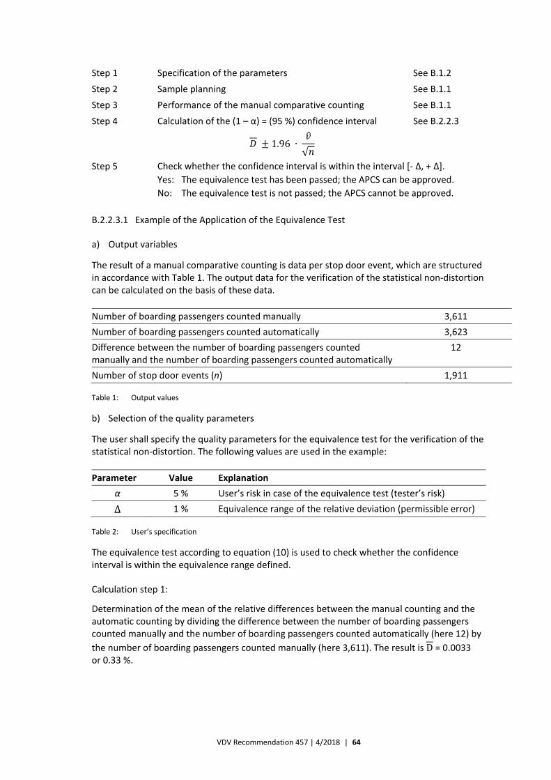
VDV Recommendation 457 | 4/2018 | 64
Step 1 Specification of the parameters See B.1.2
Step 2 Sample planning See B.1.1
Step 3 Performance of the manual comparative counting See B.1.1
Step 4 Calculation of the (1 – α) = (95 %) confidence interval See B.2.2.3
1.96 ∙
√
Step 5 Check whether the confidence interval is within the interval [‐ ∆, + ∆].
Yes: The equivalence test has been passed; the APCS can be approved.
No: The equivalence test is not passed; the APCS cannot be approved.
B.2.2.3.1 Example of the Application of the Equivalence Test
a) Output variables
The result of a manual comparative counting is data per stop door event, which are structured in accordance with Table 1. The output data for the verification of the statistical non‐distortion can be calculated on the basis of these data.
Number of boarding passengers counted manually 3,611
Number of boarding passengers counted automatically 3,623
Difference between the number of boarding passengers counted manually and the number of boarding passengers counted automatically
12
Number of stop door events (n) 1,911
Table 1: Output values
b) Selection of the quality parameters
The user shall specify the quality parameters for the equivalence test for the verification of the statistical non‐distortion. The following values are used in the example:
Parameter Value Explanation
α 5 % User’s risk in case of the equivalence test (tester’s risk)
Δ 1 % Equivalence range of the relative deviation (permissible error)
Table 2: User’s specification
The equivalence test according to equation (10) is used to check whether the confidence interval is within the equivalence range defined.
Calculation step 1:
Determination of the mean of the relative differences between the manual counting and the automatic counting by dividing the difference between the number of boarding passengers counted manually and the number of boarding passengers counted automatically (here 12) by
the number of boarding passengers counted manually (here 3,611). The result is D = 0.0033 or 0.33 %.
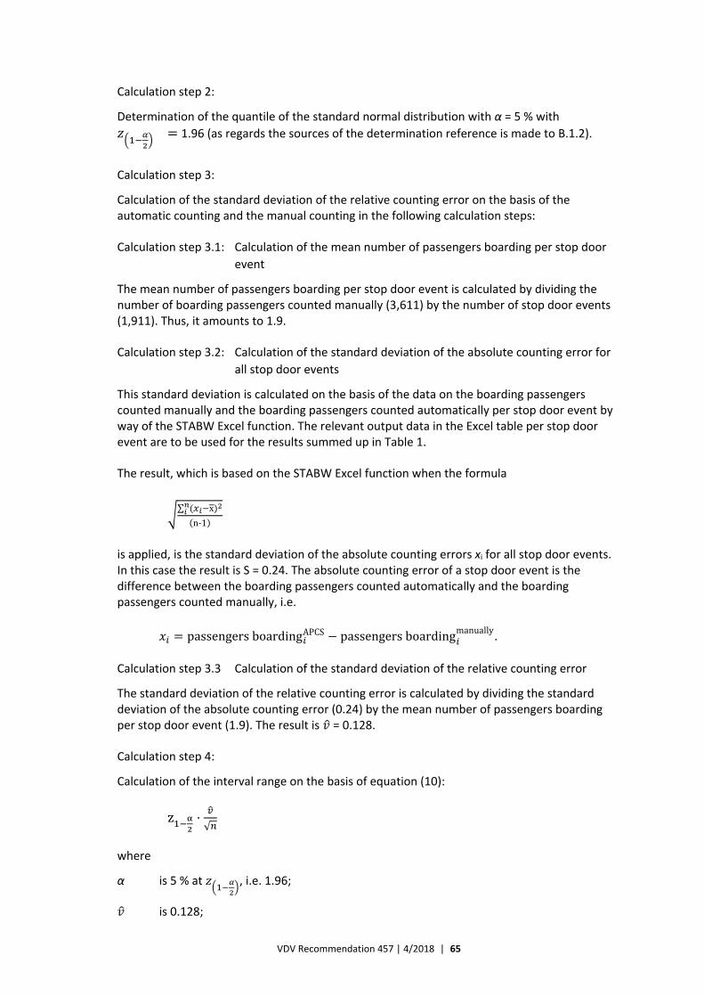
VDV Recommendation 457 | 4/2018 | 65
Calculation step 2:
Determination of the quantile of the standard normal distribution with α = 5 % with
1.96 (as regards the sources of the determination reference is made to B.1.2).
Calculation step 3:
Calculation of the standard deviation of the relative counting error on the basis of the automatic counting and the manual counting in the following calculation steps:
Calculation step 3.1: Calculation of the mean number of passengers boarding per stop door
event
The mean number of passengers boarding per stop door event is calculated by dividing the number of boarding passengers counted manually (3,611) by the number of stop door events (1,911). Thus, it amounts to 1.9.
Calculation step 3.2: Calculation of the standard deviation of the absolute counting error for
all stop door events
This standard deviation is calculated on the basis of the data on the boarding passengers counted manually and the boarding passengers counted automatically per stop door event by way of the STABW Excel function. The relevant output data in the Excel table per stop door event are to be used for the results summed up in Table 1.
The result, which is based on the STABW Excel function when the formula
∑ x
n‐1
is applied, is the standard deviation of the absolute counting errors xi for all stop door events. In this case the result is S = 0.24. The absolute counting error of a stop door event is the difference between the boarding passengers counted automatically and the boarding passengers counted manually, i.e.
passengersboardingAPCS passengersboardingmanually.
Calculation step 3.3 Calculation of the standard deviation of the relative counting error
The standard deviation of the relative counting error is calculated by dividing the standard deviation of the absolute counting error (0.24) by the mean number of passengers boarding per stop door event (1.9). The result is = 0.128.
Calculation step 4:
Calculation of the interval range on the basis of equation (10):
z ⋅√
where
α is 5 % at , i.e. 1.96;
is 0.128;
VDV Recommendation 457 | 4/2018 | 66
n is 1.911.
Thus, the value for the interval range amounts to 0.57 % or 0.0057.
Calculation step 5:
When the interval range of 0.57 % or 0.0057 is applied and when the mean of the relative
differences between the manual counting and the automatic counting amounts to 0.0033 or 0.33 % in accordance with equation (10):
z1 α2⋅√,
the result is
— a lower barrier of ‐0.0024 or 0.24 %;
— an upper barrier of 0.009 or 0.9 %.
Thus, the confidence interval [+0.0090 – ‐0,0024] is fully within the determined equivalence range of the relative deviation [+0.01 – ‐0.01] (permissible error).
The system can be accepted with the verification of the statistical non‐distortion.
B.3 End of the Revision of Comparative Counting for Certifying the Counting Accuracy
B.3.1 General Requirements
B.3.1.1 Counting Accuracy Certification
By the certification of the counting accuracy distinction is to be made between:
— initial certification before putting the APCS into operation within the scope of a comparative counting;
— event‐ or case‐related certification depending on the requirements;
— periodic re‐certification of an APCS in operation.
The below descriptions refer to the initial certification before putting the APCS into operation.
By analogy, as appropriately and depending on the actual situation, these requirements shall also be applied to event‐ or case‐related certifications after having put the APCS into operation if components, especially sensors and their firmware, are so modified that the counting accuracy is directly influenced.
The requirements for periodic re‐certification of an existing APCS are an integral part of the rules on preparation, performance and evaluation of the system acceptances for APCS background systems (see C.3).
B.3.1.2 Size of the Comparative Counting
The manual comparative counting or a comparative counting based on video recording or recording with an imaging method should preferably include all vehicles equipped with APCSs
VDV Recommendation 457 | 4/2018 | 67
of a transport company, but it shall at least include each type of vehicle, each type of door and each type of sensor. Moreover, it shall be made on lines that represent the network in respect of size, spatial and time structure of the transport volume, transport flow and special operating or technical conditions. Special features like bulk boarding (lines/journeys with e.g. many pupils at certain times of the day) and other typical situations shall always be considered. The spatial size of the area to be analysed in the form of a comparative counting shall depend on real data on the demand for transport and the transport offer.
Thus, the sample shall not only be mathematical‐statistically planned, but also always consider special features and be coordinated with the transport company in question.
B.3.2 Manual Comparative Counting for Certifying the Counting Accuracy
B.3.2.1 Requirements for Performance of the Comparative Counting
B.3.2.1.1 General Requirements
The count data shall be collected in the vehicles during the journey. It is recommended to collect them by way of electronic devices, but a count form can also be used.
The counting procedure depends on the mode of operation of the APCS. Both the occupation before the beginning of the journey and after the end of the journey as well as the passengers boarding and alighting during the journey can be counted. Depending on where the counting persons board and alight along the journey, they shall include themselves in the counting.
To assure the quality of the data collected manually, it is recommended not only to count the passengers boarding and alighting, but also the occupation so that all variables can be validated by way of the parameters, i.e. passengers boarding, passengers alighting and occupation.
In principle, all persons who board and alight by themselves (inclusive of the persons counting and the driver) are counted as passengers boarding and alighting. This also applies to the first stop and the terminal. Please see B.2.1 for special cases.
Generally, all pieces of information are collected to be able to reconstruct the real route and the journey time of the vehicle collecting the data as well as the relevant special features by the evaluation.
B.3.2.1.2 Grouping of the Ppersons Counting
The grouping of the persons counting shall always be orientated towards the objective, which is to ensure that all persons boarding and alighting are counted correctly at each door so that the data automatically collected can be validated numerically exactly and in a tamper‐proof way. Therefore, the persons counting shall be grouped in such a way that the optimal comparability with the count data generated automatically is achieved.
To fulfil this requirement, it is recommended always to let two persons count the passengers at each door with a standard width without barrier rails. One person should count the passengers boarding and the other one the passengers alighting. Alternatively, each person counts both the passengers boarding and the passengers alighting. In this case only the results with identical values are used. The optimal method depends on the vehicle, the passenger volume and the door width.

VDV Recommendation 457 | 4/2018 | 68
If the door is narrow and only allows one lane or if only boarding or alighting is allowed at a door, it is allowed to deviate from this requirement. All special cases shall be analysed separately.
If it is being considered to reduce the number of persons counting for cost reasons, it shall always be born in mind that the data are to be used for correct, consistent and tamper‐proof certification of the data collected automatically.
B.3.2.1.3 Guidelines for the Persons Counting
It shall be ensured that the data resulting from the manual comparative counting are complete, consistent, correct, traceable and tamper‐proof. This objective can be achieved by way of electronic devices or count forms.
Important parameters or data complexes are:
a) order of stops with times of departure;
b) passengers boarding/alighting;
c) passengers re‐boarding/re‐alighting at the same stop – as a subset of passengers boarding/ alighting;
d) information about the special cases according to B.2.1;
e) journey‐related comments (early departure, field for free text to describe special events);
f) stop‐related comments (bulk boarding/alighting, slow‐moving boarding/alighting, other kind of staying under the sensor, delay > 15 min);
g) occupation before the beginning of the journey and after the end of the journey;
h) field for comments, e.g. whether the person counting left the vehicle between the journeys;
i) signature by the person counting/personalised log‐in.
Figure B.1 shows a possible user surface of an electronic device.
Figure B.1: Example of a user surface of a pocket PC
Figure B.2 shows a possible count form.
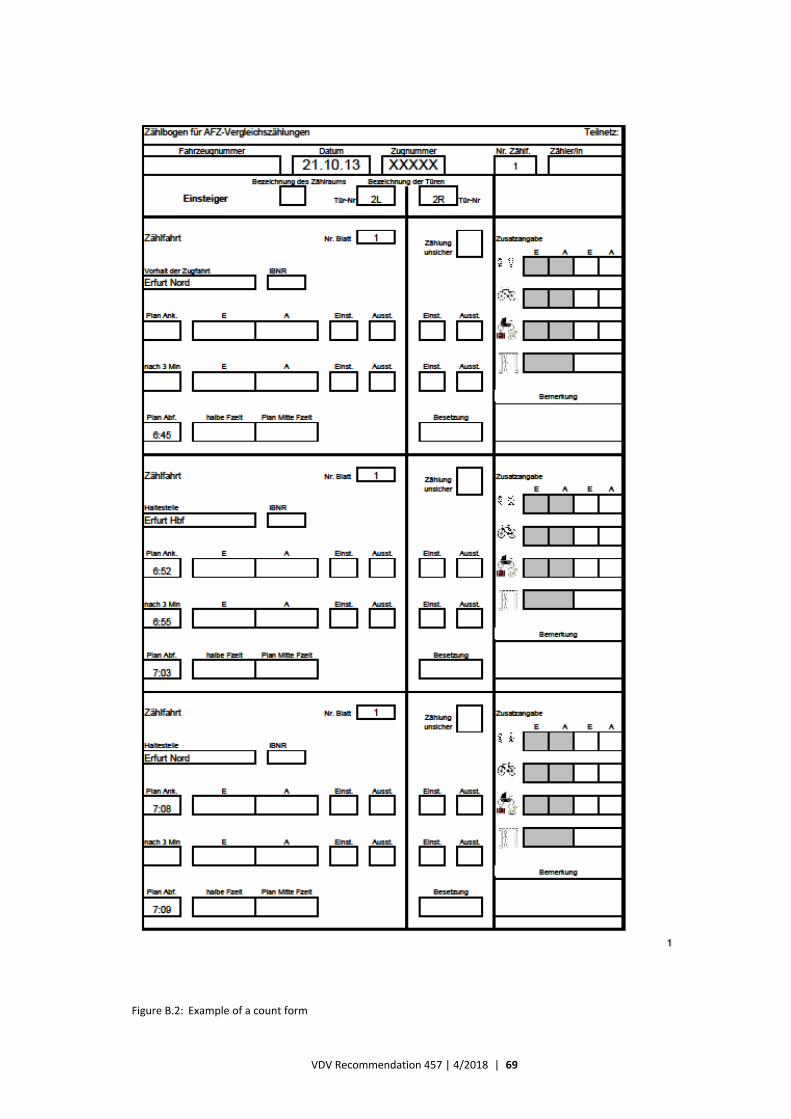
VDV Recommendation 457 | 4/2018 | 69
Figure B.2: Example of a count form

VDV Recommendation 457 | 4/2018 | 70
To begin with, the supplier and the transport company shall coordinate the user surface of the electronic device or the count form, respectively. Stop strings are used as the data basis. Timetable data are provided by the transport company.
The persons counting are briefed about the APCS. It shall be ensured that they do not affect the comparative counting by making systematic errors or inapplicable evaluations of the order of events.
The persons counting shall observe the following guidelines:
— A prepared form or a defined input mask shall be used for each count journey (from terminal to terminal). Name, date and time of day as well as counting position (door, lane) shall be entered if this information has not been noted in the form already. By analogy, this also applies to electronic devices, to which this information might have been transferred already.
— At first, the passengers boarding at the first scheduled stop are counted. In the end, the passengers alighting at the last scheduled stop are counted within the period of counting. The trips to and from the depot are not included in the counting.
— All persons counting board and alight exactly once at each terminal. By analogy, this applies at the beginning and the end of the counting. Deviations shall be noted in the field for comments.
— The persons counting shall always also count themselves and the driver as persons boarding/alighting.
— It is important always to enter the number of persons boarding and alighting at the correct stop.
Exceptions, e.g. if reliable counting is not ensured due to many passengers boarding and alighting, shall be documented.
It is required:
— to explicitly mark stops which the vehicle passes without stopping or at which no door is opened despite a halt;
— to enter “0” if the door was open and no one boarded or alighted;
— to enter all values on paper count forms (e.g. in case of ad hoc journeys) with a ballpoint or a felt pen (no pencil);
— that all entries are clear and understandable;
— to note the number of passengers boarding and alighting as slashes or figures on paper count forms. Several figures can be separated by commas (e.g. “17, 2, 1”) if several groups are to be collected;
— that the passengers alighting at the terminal are always assigned to the journey that ends at that terminal and that passengers boarding at the terminal are always assigned to the journey that begins at that terminal;
— to detect a value pair (passengers boarding and passengers alighting) before and after the “period of alighting” up to the next departure if a compensation for the “waiting room effect” has been implemented. The period of alighting is defined as the period up to which all passengers of the arriving journey have left the vehicle;
VDV Recommendation 457 | 4/2018 | 71
— to assign all passengers boarding and alighting to the same stop in case of twin stops or several halts at one stop, even if the vehicle moves forwards and if the doors are opened several times;
— that persons who board a vehicle and alight it again at the same stop to e.g. get a piece of information from the driver (passengers re‐boarding/re‐alighting at the same stop) are counted, also if they just board or alight to make room or to help with a pram or luggage. These passengers shall also be counted separately in the “passengers re‐boarding/re‐alighting at the same stop” column;
— that persons who board or alight laterally because more there are than one lane shall also be counted as passengers boarding or alighting. These passengers shall also be counted separately in the “passengers boarding/alighting laterally” column;
— that persons boarding or alighting via separate driver’s cab doors, e.g. a driver, are also counted if they board via this door and alight via a passenger door or vice versa;
— that doormen or other staff of the user who are active at stops within the range of the sensors of open doors are not counted as passengers boarding or alighting, but entered in the “doormen” column;
— that the rules specified in B.2.1 apply to the handling of persons e.g. < 120 cm;
— that further special cases, e.g.:
— small children on the arms of adults;
— rucksacks;
— dogs;
— big pieces of luggage;
— bicycles;
— walking frames;
— wheelchairs without seated persons,
are not counted as passengers boarding or alighting, but as separate special cases;
— that uncertainties about the actual number of persons, the correct column, a possible transposition of passengers boarding and passengers alighting etc. are entered separately as comments;
— that intermediate halts are included as independent stops, which shall be considered by the programming of the data‐collecting device.
B.3.2.2 Requirements for the Validation of the Comparative Counting
As soon as possible, the data shall be transferred to the server of the company in charge of the fieldwork or they shall be entered manually in its office.
Thereafter, the data shall be validated. This validation shall include at least the following:
— check for completeness;
— check for extreme values/values deviating considerably;
— check for a complete and correct order of stops;
— check for mathematical conclusiveness of the results.

VDV Recommendation 457 | 4/2018 | 72
If some results of a journey are inconclusive and cannot be explained by clear input errors and if the deviation between passengers boarding and passengers alighting exceeds 2 % per journey, the data for this journey shall be re‐collected.
Journeys stopped for operational reasons shall be rejected and the data for these journeys shall be re‐collected.
It is not allowed to manually correct the numbers of passengers boarding and alighting later. However, clear input errors may be corrected later. This also applies to the handling of passengers boarding and alighting at the terminals as regards the assignment to the relevant stop/journey in consideration of the passengers boarding and alighting at the same stop.
B.3.2.3 Documentation of the Data records
It is possible and recommended for tamper‐ and court‐proof verification to record the door‐specific comparative counting with video or image recording devices and to evaluate it afterwards, provided that the requirements for the quality assurance and the method are not modified further.
At least the following documents shall be handed over to the transport company:
— menu guide/count form;
— daily operation schedule;
— error logs.
The company in charge of the fieldwork is obligated to save the fieldwork data collected electronically or manually as well as the other count documents and to hand them over to the transport company.
B.3.2.4 Requirements for the Transfer of Data Collected Automatically
The supplier of the APCS shall ensure that data collected automatically can be converted to an Excel format or to another format agreed upon.
The APCS shall provide the following data:
— number of passengers boarding and alighting at each stop;
— unique names of the stops/stop numbers;
— clear and exact journey identification;
— identification parameters of the count journeys (line, direction, date, departure time, cycle, vehicle, order of stops) to ensure clear assignment of manual and automatic comparative journeys.
If possible, the journey identification for the automatic counting shall also be used for the manual counting.
B.3.2.5 Quality Assurance of the Comparative Counting
As the requirements for the accuracy of a manual comparative counting shall be at least as high as the requirements for the counting accuracy of the APCS, the below‐mentioned requirements are made for the quality test of the data in addition to the special requirements for the selection of the persons counting.
VDV Recommendation 457 | 4/2018 | 73
For the comparison with the figures of passengers boarding and alighting that are collected automatically only those manual count journeys shall be included for which the number of passengers boarding does not deviate by more than 2 % from the number of passengers alighting, inclusive of the passengers seated before the beginning of the journey or after the end of the journey, respectively, per journey and for which there is no further inaccuracy that cannot be plausibly corrected. All other journeys shall be excluded from further evaluation. However, the sum of boarding passengers counted manually shall not deviate by more than 1 % from the sum of alighting passengers counted manually for all journeys included in the comparative counting.
In principle, the number of passengers alighting at the first stop and the number of passengers boarding at the last stop shall be set to 0 by the evaluation of the previous journey and the following journey, respectively, if no passenger stays in the vehicle (“persons who remain seated”).
The number of passengers alighting at the first stop of the first journey of a journey chain and the number of passengers boarding at the last stop of the last journey of a journey chain shall be set to 0. The rules concerning the waiting room effect (cf. 8.2) shall be applied accordingly.
B.3.3 Comparative Counting by way of (Video) Image Recording
B.3.3.1 Kinds of Recording
Below “video” and “video recording system” mean all imaging procedures and systems that allow unambiguous detection of a single person or a defined count object per se and in his/her/its natural movement at least at the quality of state‐of‐the‐art video technologies. They do not include systems that require further interpretation, e.g. (software) logistic interpretation, to determine whether it is a single person or a defined count object.
Thanks to the application of new technologies, e.g. video sensors or other video imaging systems, in public transport vehicles and regional rail vehicles passengers boarding and alighting can either be directly counted manually by persons counting them in the vehicles, just as in case of other sensor types, or subsequently via the video image.
For this purpose, video image data have to be recorded during the comparative count journeys and be saved for the evaluation period. The following two configurations are possible for the recording:
— configuration 1: recording of video images by way of additional video cameras in the door area;
— configuration 2: recording of the video image data by the APC image sensor.
Experience from the fully manual counting in the vehicle has taught us that certain situations cannot be fully recorded. Therefore, video data recording of the boarding and alighting is recommended in addition to the manual comparative counting as it facilitates the subsequent fault analysis and evaluation.
The decision on fully manual comparative counting in the vehicle or on manual comparative counting with additional video image recording depends on the project and on economic criteria. Thus, e.g. the following should be considered by the decision‐making:
Advantages of video recording:
VDV Recommendation 457 | 4/2018 | 74
— the counting can be repeated by re‐playing the video sequence (slow motion, freeze frame etc.);
— manual counting at the computer;
— reduction of staff costs as the persons counting do not have to go to and depart from the counting vehicle;
— reduction of staff costs as the persons counting do not have “natural” count breaks like journey time between count halts;
— counting during normal working hours (less staff costs for persons counting, no costs for journeys in private cars to and from the count location);
— documentation of the boarding/alighting and the archiving.
Disadvantages of video recording:
— additional costs and technical effort for equipping the vehicle with video sensors (configuration 2) or additional video cameras (configuration 1);
— higher staff costs if persons counting are needed in addition to the additional video cameras (configuration 1);
— security aspect concerning additional cameras (passengers’ privacy protection, vandalism);
— time factor; the comparative counting is a separate project (configuration 1);
— less flexibility (exchange of vehicles; transfer of persons counting etc. (configuration 1));
— the video technology cannot detect the original occupation, i.e. counting persons are also needed).
If the manufacturer of the APCS provides a (configuration 1 or 2) video recording system, he shall describe its properties and the necessary playback software and include it in the tendering documents. The specific requirements for comparative counting by way of the video image are mentioned in the following subchapters and shall be considered.
Configuration 1 systems shall continuously record the complete count journey if the external recorder is not informed about the door state (open/closed). For this purpose, it can be connected to appropriate vehicle signals or these signals can be transferred to it. It is only allowed to deviate from this requirement if an alternative with verified reliability is proposed.
In case of configuration 2 systems the image sensors are controlled via the door signal. Therefore, it suffices to record images when the door is open and to save these video image data.
B.3.3.2 Data Security (of the Video Images) in the Vehicle
Unauthorised access to the video data during the recording in the vehicle shall be excluded by suitable technical measures. Therefore, the additional video camera (configuration 1) shall be so installed that it is covered.
B.3.3.3 Data Privacy Protection (of the Video Images) in the Vehicle
The data privacy protection rules valid in the area of operation shall always be observed.
If video images are recorded from above and without face recognition, the relevant data privacy protection rules shall be observed. Experience has taught us that the recording has to
VDV Recommendation 457 | 4/2018 | 75
be approved by the authorities for data privacy protection reasons. This aspect shall always be settled before a decision on video‐based comparative counting is made.
The supplier of a configuration 1 or configuration 2 system shall present the necessary data privacy protection approvals.
B.3.3.4 Technical Requirements for the Video Recording
It shall be ensured that video recording is made of each door opening.
All video cameras and, if relevant, the transient recorder or the data logger (e.g. for passengers detected by the APCS) shall be synchronised in time, e.g. by way of cameras with synchronisation input for the image frequency. Alternatively, a GPS‐/NTP‐based time signal can be used.
The recording is made as a video file. Compression procedures can be applied if they do not affect the evaluability of the data.
The data privacy protection rules shall be observed when the video recordings are examined and played. This requirement can be fulfilled by providing a special playback software or appropriate codes free of charge. Distortions, e.g. with fisheye lenses, are harmless as long as the video images are sufficiently sharp.
An identification text (e.g. “camera 1 bus 2”) as well as the date and the time of recording shall be faded into the video image.
Moreover, the following can occur in the image:
— count values for passengers boarding and alighting (project‐dependent);
— door number;
— time stamp (YY,MM,DD; hh,mm,ss).
As an alternative to fading information into the image, the identification, the date and the time can be saved with the video stream and shown in the playback software.
In case of continuous recording it is recommended to record the following data for the comparative counting at the video image to facilitate the subsequent evaluation:
— stops, if an appropriate signal can be received from the IBIS vehicle bus; or
— GPS positions, which are to be recorded synchronously;
— tapping of the door signal.
If the door signal is recorded, the recording is activated when the door is open and deactivated when it is closed. In this way it is possible to do without data recording between the halts (at which the door is open). If the recording is continuous, jumping to the halts with passenger turnaround shall be possible. In this case the values are to be marked with bookmarks in the playback software to allow purposive jumping in the video sequences.
If use is made of GPS coordinates, the assignment shall be independent via an assignment list (stops and coordinates), which is stored in the background system.
VDV Recommendation 457 | 4/2018 | 76
The digital recording of the video images shall be equidistant and consist of at least 12 images/sec. The geometric image resolution (number of pixels) should amount to at least 0.1 megapixel.
The vision panel of the camera shall be so selected that both passengers boarding and passengers alighting are clearly detected in the area under the sensors. The cameras shall be so selected that clear evaluation is also possible under unfavourable lighting and visibility conditions. The light sources available in the vehicle shall not be supplemented by light amplifiers (visible light and close infrared), not even in the (dark) morning and evening hours.
B.3.3.5 Requirements for the Assignment of the Manual Count Data to Timetable Journeys
If the counting accuracy is evaluated at the journey or stop level or if it is evaluated in respect of transport performance (Pkm) and transport volume (P) after a balance settlement, the manual count data (“count data flow”) shall always be assigned to the timetable data. This matching can be made in the following ways:
a) manual matching of the numbers of boarding and alighting passengers counted manually to the stops and journeys by entering the values into ready‐made tables/matrices with pre‐assigned fields for the timetable data (e.g. journey number, stop number, time of departure);
b) automatic matching of the numbers of boarding and alighting passengers counted manually to stops and journeys by way of project‐specific identification parameters to be specified (e.g. stop number, journey number) via appropriate software algorithms.
In case of b) it is important that the identification parameters are precisely recorded in the vehicle (tracking information – see above).
B.3.3.6 Requirements for the Installation/Reliability of the Devices for the Comparative Counting (Configuration 1)
The complete system shall have its own power supply system or be supplied with power via the on‐board power supply system.
The separate video system shall be so installed that the following requirements are fulfilled:
— no or little nuisance to the passengers;
— non‐accessible to passengers;
— robust, vibration‐free installation;
— robust and safe cabling (no risk of stumbling).
Moreover, it shall be accepted and confirmed by the transport company.
The deinstallation of the video cameras shall not free residues and shall also be accepted and confirmed by the transport company.
B.3.3.7 Additional Requirements for the Transfer of Data
The data volumes from the recording and storage of video images for e.g. one day can be so big that they cannot be transferred via the usual standardised data transmission paths. As regards configuration 1 it shall also be borne in mind that it is not always possible to connect
VDV Recommendation 457 | 4/2018 | 77
the additional device to the central systems in the vehicle and to the standard data transmission paths provided in the vehicles (WLAN, mobile telecommunications etc.).
In this case it shall be possible to transfer the video data to external data carriers. These data carriers shall be so labelled or the files shall be so coded that the data can be clearly assigned to a vehicle and a door as well as to a date and a time of recording.
The memory unit of the data carrier shall be so designed that it is possible to record video image data at stops of an average workday for a vehicle in line service. It shall also be possible for the operating staff of the transport company to exchange data carriers without special knowledge of data carriers.
B.3.3.8 Technical and Organisational Requirements for the Evaluation of Video‐based Comparative Counting
If possible, uniform, standardised media players should be used by the evaluation of the video images. They should have the following technical features:
— fast‐forward;
— slow motion;
— jumping to certain points (e.g. time stamps) in the video recording.
The staff (persons counting) evaluate the video images by looking at/checking the video images and manually counting the passengers boarding and alighting. Each counting person counts the passengers boarding and alighting at one door in a defined period of time on the basis of journeys selected at random within the period of collection.
The counting should be based on the four‐eyes principle, i.e. two counting persons evaluate the video recordings per stop and door on their own. Software compares the figures of the first person counting with those of the other one counting. If there are deviations, an administrator is consulted, who finally decides whether the count result is valid or not. If manual data, i.e. data collected per video, are questionable, they are to be rejected for the door in question and thus for the complete journey in question.
Time intervals are defined for the manual counting of the video images on the basis of the timetable in the period of collection. It is assumed that the vehicle is empty at the beginning and the end of the period of collection (except for one driver). The driver, who is already or still in the vehicle at the beginning or the end of the period of collection, respectively, is regarded as present before or after the time interval. It shall be ensured that there are evaluable video images to all halts in the time interval defined. If data are faulty or lacking, it shall be decided whether they are to be rejected for the door in question and thus for the complete journey in question or whether the complete day of collection is to be rejected, which might especially be relevant by the determination of the occupation.
Each time interval has a unique number. Moreover, header data with the following information are included:
— date;
— counting vehicle;
— time from/to;
— cycle according to the timetable;
VDV Recommendation 457 | 4/2018 | 78
— door number.
In principle, the data area does not differ from that of the manual counting. If, however, there is no assignment to timetable data, there are the following differences:
— a sequence number or a bookmark and the time interval are assigned to each stop so that the relevant video images can be found (more easily) later;
— the stops are not assigned to journeys;
— terminals are not considered, e.g. to compensate for the waiting room effect.
B.3.3.9 Quality Assurance
As the results of the manual comparative counting are regarded as “perfect” in the statistical sense, the persons counting the passengers via video shall be briefed about the special conditions for the evaluation of video images.
The video recordings should be kept and archived for any subsequent evaluation, provided that data privacy protection rules do not forbid this step. If so, manual count documents prepared during the video evaluation can be archived instead. In this case the above‐mentioned four‐eye principle is recommended. Thus, the video recording is available as a recording to be analysed during the project and is deleted or destroyed after the end of the project upon acceptance of all parties involved. If the result of the manual counting of the video evaluation is doubted, the manufacturer of the APCS can look into the video recording and the manual count documents.
As regards the evaluation of the transport performance (Pkm) the rules specified in B.2.1 apply. The occupation figures determined via the APCS (on the basis of the raw data of the APCS) and the “video evaluation” (i.e. the manual comparative counting on the basis of the video recording) are homogeneously multiplied by the actual distances on the basis of the actual distances stored. If the timetable data do not include actual distances, the actual distances of the APCS can be used instead.
It always has to be ensured that identical distance data are used for the Pkm from the APCS and for the Pkm from the video evaluation. Moreover, it shall be ensured that only stops for which there are values from both the APCS and the video evaluation are included in the evaluation of the Pkm. If the occupation is negative, there is no such pairwise evaluation of the Pkm (see B.2.1).
VDV Recommendation 457 | 4/2018 | 79
Annex C: Rules for Accepting a Background System
C.1 Objective
When the APCS is to be accepted, the specifications and functions of the APCS background system (APCS‐BGS), which are defined in the target specification and the performance specification, shall be examined.
The below‐mentioned acceptance criteria are a test criteria guideline and recommended by experts. The project‐specific system architecture as well as the organisational and process structure of the APCS are decisive for the application of the test criteria. Thus, e.g. the count journey planning test steps are superfluous if all vehicles are equipped with APCSs.
Bearing these project‐specific criteria in mind, the following test contents are recommended:
a) export and import of target data and actual data;
b) count journey planning:
— sample planning;
— random selection of count journeys;
— availability of count journeys in the timetable/cycle;
c) check/correction of count journeys (monitoring);
d) extrapolation;
e) further functions:
— analysis of the quality of the P/Pkm count data;
— transformation quote;
— transfer of manual counting information;
f) re‐certification of the counting accuracy.
This system‐neutral description does not consider specific organisational and process structures by the operation of an APCS. In the specific case the test steps shall be adapted to specific features (e.g. use of integrated clients).
Within the scope of the system acceptance it is verified with real values or reference data whether expected, estimated values are generated during the complete process chain for the transport volume (P) population and the transport performance (Pkm) population in the organisational and process structure defined and in the resulting system architecture.
Beside the content and functional requirements for the APCS‐BGS especially the interfaces to the supply of the APCS‐BGS with target data and actual data as well as the functional interaction between the APCS‐BGS and the transport companies shall be tested in the form of reference applications.
The complete process chain up to the extrapolation shall be examined by an external expert within the scope of the system acceptance.
The result of this system acceptance is a condition for the formal acceptance of the APCS.
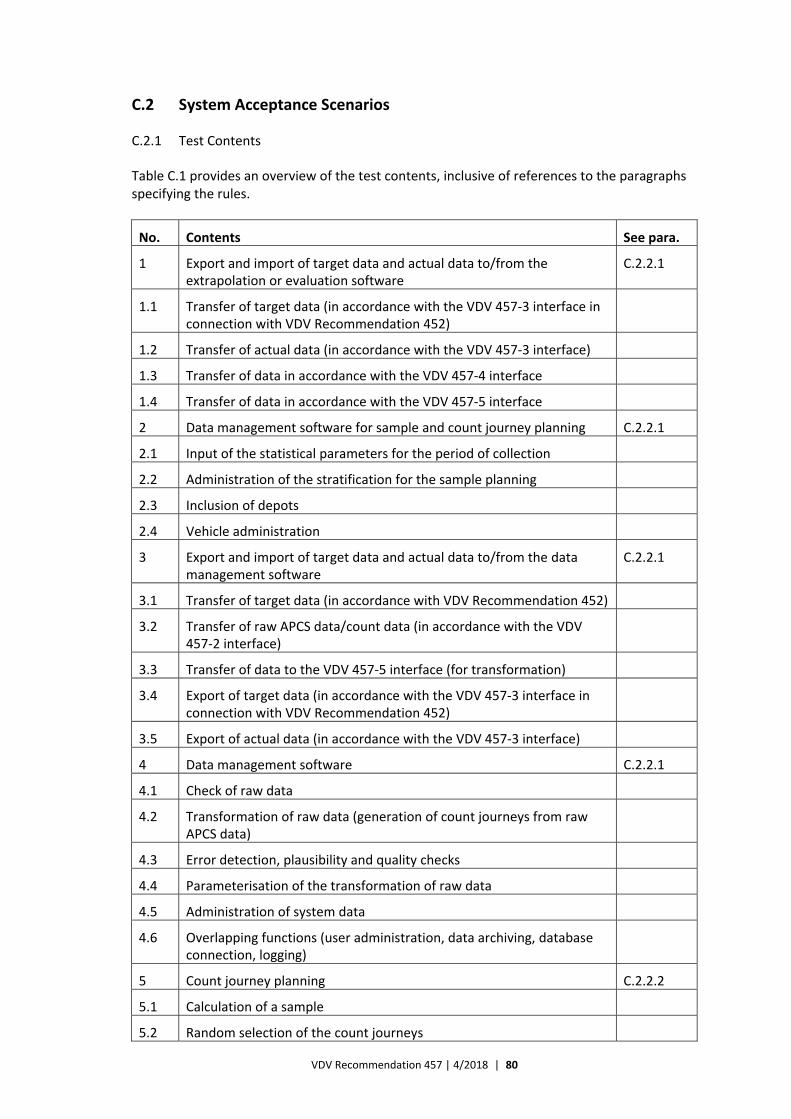
VDV Recommendation 457 | 4/2018 | 80
C.2 System Acceptance Scenarios
C.2.1 Test Contents
Table C.1 provides an overview of the test contents, inclusive of references to the paragraphs specifying the rules.
No. Contents See para.
1 Export and import of target data and actual data to/from the extrapolation or evaluation software
C.2.2.1
1.1 Transfer of target data (in accordance with the VDV 457‐3 interface in connection with VDV Recommendation 452)
1.2 Transfer of actual data (in accordance with the VDV 457‐3 interface)
1.3 Transfer of data in accordance with the VDV 457‐4 interface
1.4 Transfer of data in accordance with the VDV 457‐5 interface
2 Data management software for sample and count journey planning C.2.2.1
2.1 Input of the statistical parameters for the period of collection
2.2 Administration of the stratification for the sample planning
2.3 Inclusion of depots
2.4 Vehicle administration
3 Export and import of target data and actual data to/from the data management software
C.2.2.1
3.1 Transfer of target data (in accordance with VDV Recommendation 452)
3.2 Transfer of raw APCS data/count data (in accordance with the VDV 457‐2 interface)
3.3 Transfer of data to the VDV 457‐5 interface (for transformation)
3.4 Export of target data (in accordance with the VDV 457‐3 interface in connection with VDV Recommendation 452)
3.5 Export of actual data (in accordance with the VDV 457‐3 interface)
4 Data management software C.2.2.1
4.1 Check of raw data
4.2 Transformation of raw data (generation of count journeys from raw APCS data)
4.3 Error detection, plausibility and quality checks
4.4 Parameterisation of the transformation of raw data
4.5 Administration of system data
4.6 Overlapping functions (user administration, data archiving, database connection, logging)
5 Count journey planning C.2.2.2
5.1 Calculation of a sample
5.2 Random selection of the count journeys
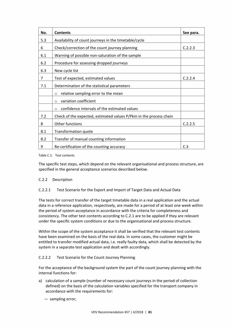
VDV Recommendation 457 | 4/2018 | 81
No. Contents See para.
5.3 Availability of count journeys in the timetable/cycle
6 Check/correction of the count journey planning C.2.2.3
6.1 Warning of possible non‐saturation of the sample
6.2 Procedure for assessing dropped journeys
6.3 New cycle list
7 Test of expected, estimated values C.2.2.4
7.1 Determination of the statistical parameters
o relative sampling error to the mean
o variation coefficient
o confidence intervals of the estimated values
7.2 Check of the expected, estimated values P/Pkm in the process chain
8 Other functions C.2.2.5
8.1 Transformation quote
8.2 Transfer of manual counting information
9 Re‐certification of the counting accuracy C.3
Table C.1: Test contents
The specific test steps, which depend on the relevant organisational and process structure, are specified in the general acceptance scenarios described below.
C.2.2 Description
C.2.2.1 Test Scenario for the Export and Import of Target Data and Actual Data
The tests for correct transfer of the target timetable data in a real application and the actual data in a reference application, respectively, are made for a period of at least one week within the period of system acceptance in accordance with the criteria for completeness and consistency. The other test contents according to C.2.1 are to be applied if they are relevant under the specific system conditions or due to the organisational and process structure.
Within the scope of the system acceptance it shall be verified that the relevant test contents have been examined on the basis of the real data. In some cases, the customer might be entitled to transfer modified actual data, i.e. really faulty data, which shall be detected by the system in a separate test application and dealt with accordingly.
C.2.2.2 Test Scenario for the Count Journey Planning
For the acceptance of the background system the part of the count journey planning with the internal functions for:
a) calculation of a sample (number of necessary count journeys in the period of collection defined) on the basis of the calculation variables specified for the transport company in accordance with the requirements for:
— sampling error;
VDV Recommendation 457 | 4/2018 | 82
— confidence level;
— variation coefficient (relative spread);
— population (number of planned journeys in the period of collection);
b) random selection of count journeys;
c) availability of count journeys (inclusive of all interfaces);
is verified by creating a sample.
C.2.2.2.1 Calculation of a Sample
The customer or an external expert shall examine the calculation for the number of necessary count journeys in the defined period of collection on the basis of the calculation variables and the statistical parameters specified (sampling error, confidence level, variation coefficient and population) in the period of collection and make a binding statement on the observance of the statistical requirements for the sampling planning within the scope of the certification.
The calculated sample is accepted if it has been calculated correctly on the basis of the specified parameters of the population, i.e. the maximum permissible sampling error, the significance level and the variation coefficient, and on the basis of the stratification structure defined.
C.2.2.2.2 Random/Equiprobable and Proportional Selection of Count Journeys
Within the scope of the acceptance it shall be tested whether the count journeys selected for the sample have been selected by random, i.e. whether the principle of equal selection probability has been observed. Moreover, it shall be verified that the selection was made proportionally to the population (population of all journeys in the period of collection) in respect of size and time.
Thus, it shall be tested whether all journeys are included in the sample at the same selection probability. Moreover, it shall be tested whether the information about the operational restrictions of the collection in the form of e.g. building or event measures, which the customer has provided, is considered by the distribution of the selected count journeys.
At this stage of the acceptance the kind and strength of the correlation between the planned journeys and the count journeys shall be determined and verified by way of regression and correlation calculations within the scope of a mathematical‐statistical analysis. Moreover, it shall be examined whether the structure within the population of planned journeys has been realised adequately with the selected count journeys, i.e. whether the various strata like lines, line variants, kind‐of‐day strata and time strata as well as seasonal strata have been considered.
The data shall be transferred to the customer or the external expert by the supplier of the background system as planned journeys and actual journeys in the diversification arising due to the above‐mentioned stratification parameters.
If there is significant dependency between the planned journeys and the count journeys, which is expressed by the correlation coefficient r in the form of r > 0.8 > maximum random value of the correlation coefficient rZ, the random, equiprobable and proportional selection of count journeys is confirmed. Thus, it is analysed whether the correlation between the time structure of the planned journeys and the selected count journeys is statistically reliable.
VDV Recommendation 457 | 4/2018 | 83
C.2.2.2.3 Availability of Count Journeys in the Timetable/Cycle
Jt this stage it is tested whether the journeys or cycles, which have been selected by random for the sample in consideration of all restrictions by the administration of the availability of the vehicles in respect of level of equipment, availability, distribution of locations and other restrictions, can be assigned to the existing timetables/cycle plans and operated accordingly. The acceptance also includes simulation of modified availability of the vehicles as well as simulation of modified target data and parameters. Moreover, the reaction of the system is tested.
C.2.2.3 Check/Correction of the Count Journey Planning
By analogy to the acceptance of the count journey planning the non‐fulfilment of count journeys according to strata as well as the preparation of a new list for the count journeys on the basis of actual events or by deletion of count journeys are simulated at the stage of check/ correction of count journeys.
The following acceptance criteria shall be observed:
— detection of non‐fulfilment of count journeys within the period remaining for necessary reactions;
— statistical assessment of the dropped journeys in respect of their relevance to the strata‐conform fulfilment of the sample in proportion to the population;
— preparation of a new cycle list for the – now assessed – selection of journeys for the complete, strata‐conform fulfilment of the sample plan.
At this stage it shall be tested whether the APCS‐BGS supplier’s calculations concerning the statistical assessment of the dropped journeys, which make up the basis for the selection for assignment into the new cycle list, are correct and whether the possible saturation of the original sample is correct according to the population and the stratification parameters.
Thus, depending on the relevant organisational and process structure, the functional interrelation between several organisational units of a transport company or the competent levels of a transport association can be tested in a comprehensive APCS by way of these test scenarios.
The following is included:
— transfer of specifications for the count journey planning by the APCS‐BGS;
— availability within the transport company with logging;
— feedback function to the APCS‐BGS with status of realisation;
— monitoring of the APCS‐BGS on the basis of the status of realisation;
— estimation of the degree of saturation of the sample;
— statistical assessment of the dropped journeys;
— transfer of new specifications for the count journey planning by the APCS‐BGS;
— availability within the transport company with logging;
— feedback function to the APCS‐BGS with status of realisation.
VDV Recommendation 457 | 4/2018 | 84
C.2.2.4 Test of Expected, Estimated Values
For the acceptance of the process chain and thus for all count data preparation steps (plausibility tests, transformation as well as balance settlement and extrapolation) it shall be verified with this test scenario that statistically reliable estimated values have been reached for the transport volume (P) and the transport performance (Pkm) for a defined period across all process chain steps in a comparison with a statistically consistent manual extrapolation from the sample to the population. If it is not possible to provide data from comparative counting, data files from journeys already collected shall be applied in the test.
This test step includes the test about deviation of the results of the comparative counting from the actual result after completion of all process chain steps.
For the background systems, which are part of the process chain, and thus for the following steps:
— check and transformation of raw data;
— preparation of count data (balance settlement);
— extrapolation,
a test scenario based on the data of the comparative counting is used as described below to certify the counting accuracy for the parameters P and Pkm.
C.2.2.4.1 Reference Values
The reference values for the counting accuracy for the parameters P and Pkm result from the comparative counting to certify the counting accuracy. Originally, the certification of the counting accuracy is the test for observance of the counting accuracy at the sensors without further process steps (e.g. balance settlement), which does not suffice for the final evaluation of the application of the data as expected, estimated values.
C.2.2.4.2 Test Step 1
Calculation of the transport volume/transport performance of the APCS, which is determined on the basis of the sample for the comparative counting, across all process chain steps to demonstrate that the expected, estimated values have been reached for the P/Pkm para‐meters within a defined period of time (e.g. count period) or a defined area (e.g. fare zone) when all calculation steps in the process chain have been passed on the basis of APCS data.
Step 1.1 transfer of the raw data
Step 1.2 analysis of the quality of the data
Step 1.3 transformation (transformation quote)
Step 1.4 balance settlement
Step 1. 5 extrapolation
Step 1.6 calculation of the expected, estimated values P and Pkm in the context with statements about the following statistical parameters:
— sampling error;
— upper and lower limits of the confidence intervals;
— variation coefficient (means/relative spread).
VDV Recommendation 457 | 4/2018 | 85
C.2.2.4.3 Test Step 2
It is assumed that consistent APCS data are available from either a comparative counting or another sample for a defined period of time and that these data are to be extrapolated to the population by the background system. Faulty data records are to be eliminated for both the manual extrapolation and the automatic extrapolation.
At this test step the results that are calculated by the APCS‐BGS when all calculation steps, inclusive of the balance settlement, have been passed, are compared with the result of a statistically consistent manual extrapolation of the sample to the population.
For this purpose, the APCS data (P and Pkm) that are extrapolated via the background system after the balance settlement are to be compared with the APCS data for P and Pkm that are extrapolated manually.
In this connection the confidence interval is generated for the value that is extrapolated to the reference period (e.g. period of collection) on the basis of the APCS data from the sample of the comparative counting, which were automatically counted and processed by the APC‐BGS. The confidence interval shall not exceed ±5 %. If it exceeds this maximum value, the sample shall be increased.
The confidence interval is generated in the same way for the values of the APCS data of the sample of the comparative counting, which are manually extrapolated, by way of the calculated sampling error. This confidence interval shall not exceed ±5 % either. If it exceeds this maximum value, the sample shall be increased subsequently.
C.2.2.4.4 Acceptance Criterion
It shall be verified that the expected, estimated value of the extrapolation, which is calculated on the basis of the validation with the background system, does not deviate more than ±5 % from the expected, estimated value determined in the manual extrapolation.
C.2.2.5 Other Functions
C.2.2.5.1 Transformation Quote
The required transformation quote shall be calculated on the basis of the real data from the system acceptance so that it can be assessed whether it is fulfilled. The transformation quote is calculated by way of the following equation:
%100RDÜ
ADHGSTQ F
FE
where
ETQ is the fulfilment of the transformation quote;
FADHGS is the number of detected count journeys of a vehicle per time unit that fulfil all test criteria;
FRDÜ is the number of planned journeys actually performed by a vehicle per time unit.
A transformation quote of ≥ 95 % is recommended.
VDV Recommendation 457 | 4/2018 | 86
C.2.2.5.2 Transfer of the Manual Counting Information
It shall be verified that manual counting data used in comparative counting and manual counting data used to supplement automatic counting (e.g. external count data that have been taken over via the relevant specific interfaces e.g. for operational reasons) can be marked as external count data and extrapolated as expected, estimated values on the basis of a standardised procedure.
C.3 Re‐certification of the Counting Accuracy via Data from the Background System
C.3.1 Task
It is a requirement for periodic and event‐related re‐certification of the counting accuracy of the sensors that a mathematical‐statistical solution with reference to the relation between passengers boarding and passengers alighting is implemented in the APCS‐BGS. Adequate models and test procedures are described below for the journey level.
The objective is an automatic test procedure for all vehicles via the APCS‐BGS or in a special subsystem. It shall be ensured that it is only possible to apply procedures that consider the comparison of boarding and alighting passengers counted automatically, the reference to the standardised results of the comparative counting and the test for statistical non‐distortion. It is assumed that the test is performed per vehicle, but it shall be performed for at least each type of sensor, each type of door and each firmware version.
C.3.2 Mathematical‐statistical Approaches
It is the objective to apply a procedure for testing the mathematical‐statistical correlation between the boarding and alighting passengers counted automatically and the boarding and alighting passengers counted automatically within the scope of the certified, journey‐related counting. This procedure shall be implemented in the BGS.
The mathematical‐statistical background of this approach is the statistical correlation between boarding passengers (B) counted automatically and alighting passengers (A) counted automatically per journey. This correlation is to be determined when the statististical non‐distortion test has been passed.
It is assumed that the statistical correlation also results for boarding and alighting passengers counted automatically during the regular operation. It is determined on the basis of the difference between boarding and alighting passengers counted automatically and boarding and alighting passengers counted manually, which has been verified in respect of statistical non‐distortion.
The mathematical‐statistical correlation between the boarding and alighting passengers counted automatically shall be determined as the reference function as a result of the certification of the counting accuracy.
If the regression function is linear, the following results:
Bauto. certified = a ∙ Aauto. certified + b
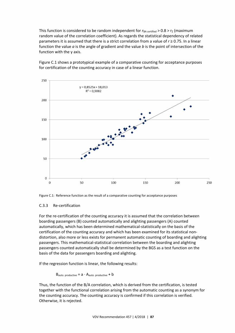
VDV Recommendation 457 | 4/2018 | 87
This function is considered to be random independent for rBA certified > 0.8 > rZ (maximum random value of the correlation coefficient). As regards the statistical dependency of related parameters it is assumed that there is a strict correlation from a value of r ≥ 0.75. In a linear function the value a is the angle of gradient and the value b is the point of intersection of the function with the y axis.
Figure C.1 shows a prototypical example of a comparative counting for acceptance purposes for certification of the counting accuracy in case of a linear function.
Figure C.1: Reference function as the result of a comparative counting for acceptance purposes
C.3.3 Re‐certification
For the re‐certification of the counting accuracy it is assumed that the correlation between boarding passengers (B) counted automatically and alighting passengers (A) counted automatically, which has been determined mathematical‐statistically on the basis of the certification of the counting accuracy and which has been examined for its statistical non‐distortion, also more or less exists for permanent automatic counting of boarding and alighting passengers. This mathematical‐statistical correlation between the boarding and alighting passengers counted automatically shall be determined by the BGS as a test function on the basis of the data for passengers boarding and alighting.
If the regression function is linear, the following results:
Bauto. productive = a ∙ Aauto. productive + b
Thus, the function of the B/A correlation, which is derived from the certification, is tested together with the functional correlation arising from the automatic counting as a synonym for the counting accuracy. The counting accuracy is confirmed if this correlation is verified. Otherwise, it is rejected.
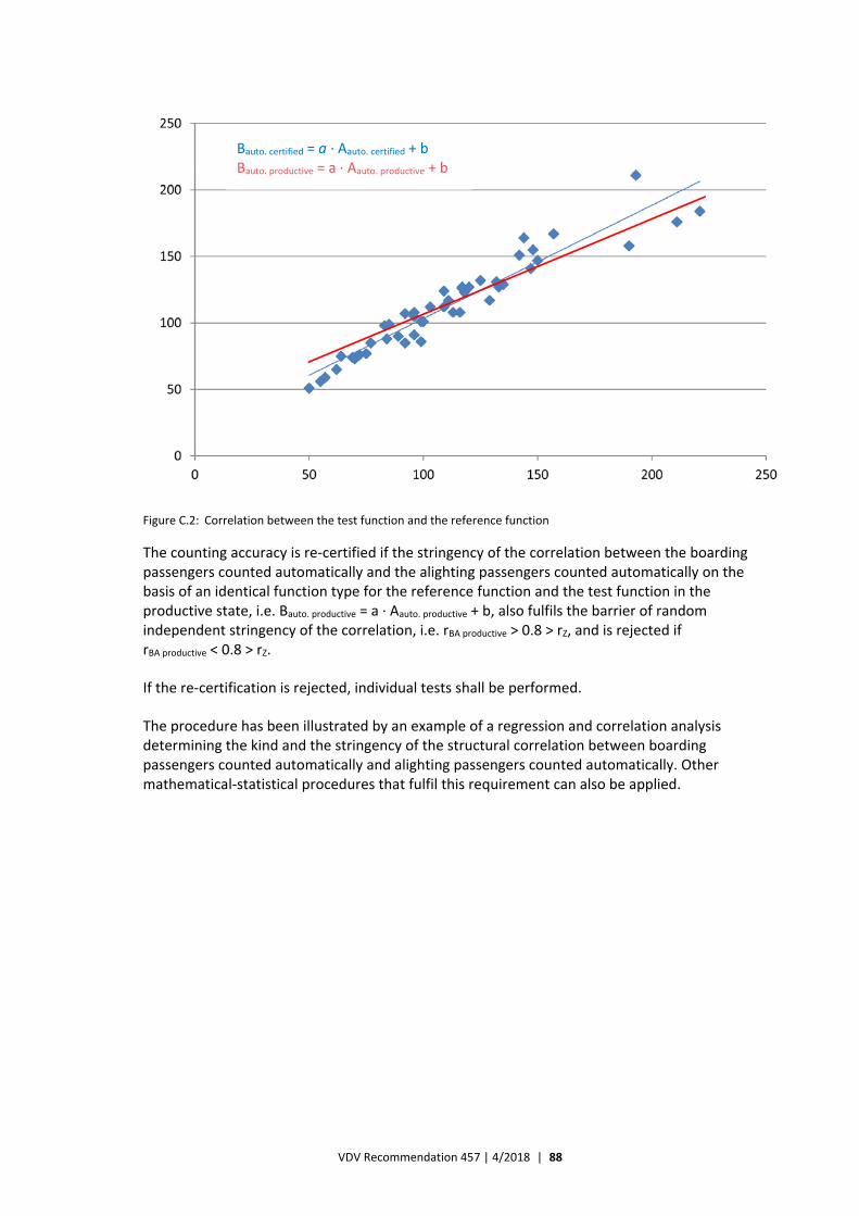
VDV Recommendation 457 | 4/2018 | 88
Figure C.2: Correlation between the test function and the reference function
The counting accuracy is re‐certified if the stringency of the correlation between the boarding passengers counted automatically and the alighting passengers counted automatically on the basis of an identical function type for the reference function and the test function in the productive state, i.e. Bauto. productive = a ∙ Aauto. productive + b, also fulfils the barrier of random independent stringency of the correlation, i.e. rBA productive > 0.8 > rZ, and is rejected if rBA productive < 0.8 > rZ.
If the re‐certification is rejected, individual tests shall be performed.
The procedure has been illustrated by an example of a regression and correlation analysis determining the kind and the stringency of the structural correlation between boarding passengers counted automatically and alighting passengers counted automatically. Other mathematical‐statistical procedures that fulfil this requirement can also be applied.
Eaut produktiv = a Aaut produktiv + b
Eaut testiert = a Aaut testiert + b Bauto. certified = a ∙ Aauto. certified + b Bauto. productive = a ∙ Aauto. productive + b
VDV Recommendation 457 | 4/2018 | 89
Annex D: Framework Specification
D.1 Preliminary Remarks about the Framework Specification
The basis for a call for tenders for automatic passenger counting systems (APCSs) is a specification that includes all functional and cost‐relevant requirements for the APCS in respect of:
— the vehicle equipment – on‐board systems see D.2
— the background systems see D.3
— the data integration on the basis of the VDV data model see D.4
This framework specification is intended to be a support by the specification of the requirements for the APCS, which is to be made by the transport company preparing the concrete call for tenders.
A uniform structure of specifications supports calls for tenders for data processing systems and for further functional areas.
Especially the compatibility of e.g.:
— the on‐board system;
— the data transfer to the background system;
— the background system
shall be ensured.
Moreover, a uniform requirements specification at the functional level and with defined interfaces for:
— sensors and the OBU;
— raw data and the background system;
— the background system and the downstream systems
shall ensure compatibility for the suppliers.
The framework specification is only and can only serve as a basis for a concrete specification. It does not replace thorough analysis of the actual conditions and the objectives for the application of the APCS in the concrete transport company. Thus, it can neither be regarded as complete nor as universally applicable.
The specific requirements of the tendering transport company shall be specified on the basis of the concrete situation and feasible options. Therefore, the framework specification is also available in a Word version.
In this sense, the framework specification does not only include the requirements, but also comments for better understanding and easier handling as well as examples. These comments and examples should not be included in the actual specification of the transport company and are therefore written in italics.
VDV Recommendation 457 | 4/2018 | 90
The complete framework specification shall always be seen in context with the contents of the relevant chapters of this VDV Recommendation.
D.2 Vehicle Equipment – On‐board Systems
D.2.1 Fundamentals, Context and Requirements
The below descriptions do not refer to products available on the market and are expressly considered to be product‐ and system‐neutral. Thus, the functional requirements specified in D.2 and D.3 can be assigned to either the vehicle (if it is supplied with e.g. the valid timetable/ network data) or the background system. It shall be borne in mind that differences between the timetable or network data in the vehicle and the background system can lead to complications.
The vehicle equipment shall consist of a central basic vehicle component, the so‐called APC on‐board unit (APC‐OBU) (see “Abbreviations / Terms and Definitions”) and one or several state‐of‐the‐art components for detection of passengers. The APC‐OBU monitors and controls the transfer of data to and from these components, which are mainly state‐of‐the‐art sensors or other kinds of detection systems and which are to be fitted in the vehicle in a vandalism‐proof, fail‐safe way and so that unauthorised persons cannot access them.
Figure D.1 shows a prototypical system configuration of an APCS. It only illustrates the state of the art and does not exclude further development. Innovations are always welcome and desired.
The transformation, the count journey planning and the extrapolation are regarded as functions that can be realised in one or several programme modules. Therefore, there are one or several interfaces.
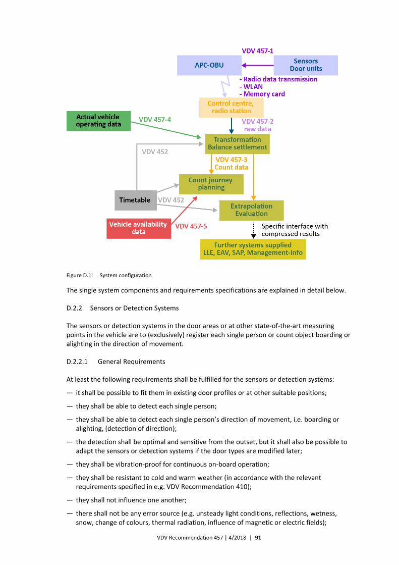
VDV Recommendation 457 | 4/2018 | 91
Figure D.1: System configuration
The single system components and requirements specifications are explained in detail below.
D.2.2 Sensors or Detection Systems
The sensors or detection systems in the door areas or at other state‐of‐the‐art measuring points in the vehicle are to (exclusively) register each single person or count object boarding or alighting in the direction of movement.
D.2.2.1 General Requirements
At least the following requirements shall be fulfilled for the sensors or detection systems:
— it shall be possible to fit them in existing door profiles or at other suitable positions;
— they shall be able to detect each single person;
— they shall be able to detect each single person’s direction of movement, i.e. boarding or alighting, (detection of direction);
— the detection shall be optimal and sensitive from the outset, but it shall also be possible to adapt the sensors or detection systems if the door types are modified later;
— they shall be vibration‐proof for continuous on‐board operation;
— they shall be resistant to cold and warm weather (in accordance with the relevant requirements specified in e.g. VDV Recommendation 410);
— they shall not influence one another;
— there shall not be any error source (e.g. unsteady light conditions, reflections, wetness, snow, change of colours, thermal radiation, influence of magnetic or electric fields);
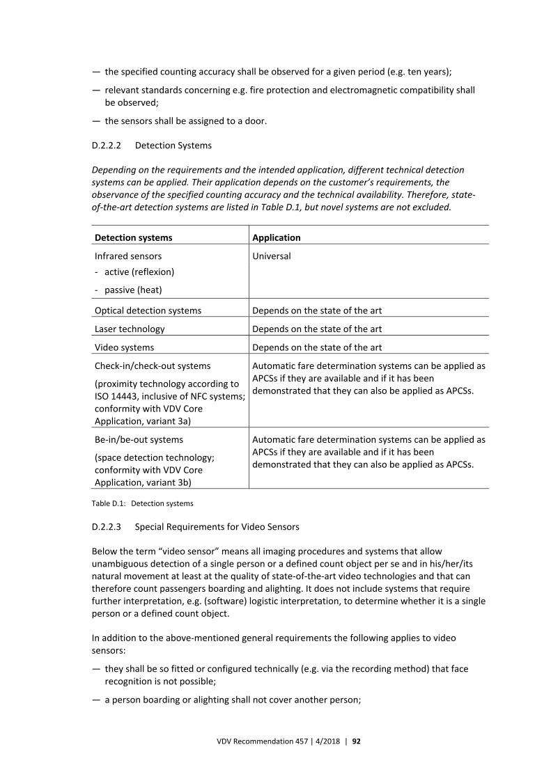
VDV Recommendation 457 | 4/2018 | 92
— the specified counting accuracy shall be observed for a given period (e.g. ten years);
— relevant standards concerning e.g. fire protection and electromagnetic compatibility shall be observed;
— the sensors shall be assigned to a door.
D.2.2.2 Detection Systems
Depending on the requirements and the intended application, different technical detection systems can be applied. Their application depends on the customer’s requirements, the observance of the specified counting accuracy and the technical availability. Therefore, state‐of‐the‐art detection systems are listed in Table D.1, but novel systems are not excluded.
Detection systems Application
Infrared sensors Universal
‐ active (reflexion)
‐ passive (heat)
Optical detection systems Depends on the state of the art
Laser technology Depends on the state of the art
Video systems Depends on the state of the art
Check‐in/check‐out systems
(proximity technology according to ISO 14443, inclusive of NFC systems; conformity with VDV Core Application, variant 3a)
Automatic fare determination systems can be applied as APCSs if they are available and if it has been demonstrated that they can also be applied as APCSs.
Be‐in/be‐out systems
(space detection technology; conformity with VDV Core Application, variant 3b)
Automatic fare determination systems can be applied as APCSs if they are available and if it has been demonstrated that they can also be applied as APCSs.
Table D.1: Detection systems
D.2.2.3 Special Requirements for Video Sensors
Below the term “video sensor” means all imaging procedures and systems that allow unambiguous detection of a single person or a defined count object per se and in his/her/its natural movement at least at the quality of state‐of‐the‐art video technologies and that can therefore count passengers boarding and alighting. It does not include systems that require further interpretation, e.g. (software) logistic interpretation, to determine whether it is a single person or a defined count object.
In addition to the above‐mentioned general requirements the following applies to video sensors:
— they shall be so fitted or configured technically (e.g. via the recording method) that face recognition is not possible;
— a person boarding or alighting shall not cover another person;

VDV Recommendation 457 | 4/2018 | 93
— it shall be avoided that the sensors are covered by fitting them at a suitable height over the area in which the passengers boarding and alighting are to be counted;
— they shall be so set that recording at the edges of the area to be detected does not affect the counting accuracy significantly.
In addition to the actual counting of passengers boarding and alighting and the subsequent provision of the count values, the APCS shall be able provide video recordings for e.g. comparative counting.
It shall also be possible for the user to switch video recordings on and off via a service software by way of parameters stored in the background system or on a central APC unit or a door unit.
Other cameras that have been temporarily or permanently fitted in the vehicle for other applications can also be used for the comparative counting recordings. The requirements for such camera systems are specified in B.3.3.4.
The useful lives of the video sensors shall correspond to those of other sensor types.
It should be possible to detect children (also on the arms of adults), bicycles, prams, walking frames, big dogs, big pieces of luggage, wheelchairs and persons boarding or alighting laterally with the video sensors. These count objects are to be separately detected so that these values can be separately transferred to the interfaces (see Annex E, E.1 – E.3).
D.2.2.4 Sensor Groups
If the door clearance is relatively big, it can be necessary to install several sensors to detect several persons alighting and boarding simultaneously. Usually, the sensors for a door are united to a group.
It is also possible to make further superior sensor groups for a vehicle that has several doors or for a train unit that consists of several vehicles.
D.2.3 Signals Needed
D.2.3.1 Door and Route Signals
The count technology is only activated when the vehicle stands still and its doors are opened (boarding and alighting). To detect this state, the APC‐OBU always need information about both criteria.
Moreover, special features shall be considered, e.g.:
— halts at stops without opening the doors and without passenger turnaround;
— passing of halts, halts upon demand;
— halts on route;
— halts at twin stops, i.e. at stops at which the doors are opened and closed several times;
— multiple starting at the same stop during a line‐service journey;
— counting at transition or intermediate doors.
VDV Recommendation 457 | 4/2018 | 94
D.2.3.2 Door Signals
The “door open” signal, which initiates the counting, and the “door closing” signal, which stops the counting, are to be directly transferred to the APC‐OBU via the existing on‐board technology or via separate door sensors for each door. It shall be possible to open the doors at least twice at each location (e.g. during the operation in winter). The counting shall also be activated if only one or some doors of a vehicle are opened. Only the count sensors of the open door(s) shall be activated.
If video‐based sensors (or imaging procedures) are applied (see D.2.2), the door state (open, closed) shall also always be determined via the software logistics of the sensors on the basis of the image information. In this case there is no need to connect the door signal.
The sensor/door component shall immediately detect the opening or closing of a door, also in case of visual detection of the door opening or without application of the door contact/signal. It shall be ensured that passenger turnaround is not detected and that boarding or alighting passengers are not counted when the door is closed.
D.2.4 Central APC Components in the Vehicle
D.2.4.1 General Requirements
As the central basic vehicle component, the APC on‐board unit (APC‐OBU) monitors and controls the transfer of data to and from the door components and checks the technical plausibility. These data are stored temporarily. The APC‐OBU shall be able to detect errors and malfunctions and to mark the relevant count data accordingly. The fault message shall be transferred simultaneously to both the diagnostic system of the vehicle and the back office to avoid that faulty count journeys are recorded for a long time.
In the simplest case all door sensors are connected to the same APC‐OBU in the vehicle. Hierarchic and/or parallel arrangements can be realised if e.g. several sensors are united to a group.
The following signals/parameters are to be provided and transferred to the APC‐OBU:
— vehicle number (optional);
— door release signal;
— door signal (optional);
— route signal (route/speed);
— sensor (group) identification (configuration of the system);
— fault messages;
— time, date, etc.
— tracking (logical, physical, GPS, see D.2.6).
Depending on the technical solution of the APC‐OBU, the following data and tasks can also be transferred (tagging):
— line, course, direction.
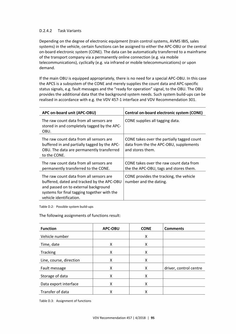
VDV Recommendation 457 | 4/2018 | 95
D.2.4.2 Task Variants
Depending on the degree of electronic equipment (train control systems, AVMS IBIS, sales systems) in the vehicle, certain functions can be assigned to either the APC‐OBU or the central on‐board electronic system (CONE). The data can be automatically transferred to a mainframe of the transport company via a permanently online connection (e.g. via mobile telecommunications), cyclically (e.g. via infrared or mobile telecommunications) or upon demand.
If the main OBU is equipped appropriately, there is no need for a special APC‐OBU. In this case the APCS is a subsystem of the CONE and merely supplies the count data and APC‐specific status signals, e.g. fault messages and the “ready for operation” signal, to the OBU. The OBU provides the additional data that the background system needs. Such system build‐ups can be realised in accordance with e.g. the VDV 457‐1 interface and VDV Recommendation 301.
APC on‐board unit (APC‐OBU) Central on‐board electronic system (CONE)
The raw count data from all sensors are stored in and completely tagged by the APC‐OBU.
CONE supplies all tagging data.
The raw count data from all sensors are buffered in and partially tagged by the APC‐OBU. The data are permanently transferred to the CONE.
CONE takes over the partially tagged count data from the the APC‐OBU, supplements and stores them.
The raw count data from all sensors are permanently transferred to the CONE.
CONE takes over the raw count data from the the APC‐OBU, tags and stores them.
The raw count data from all sensors are buffered, dated and tracked by the APC‐OBU and passed on to external background systems for final tagging together with the vehicle identification.
CONE provides the tracking, the vehicle number and the dating.
Table D.2: Possible system build‐ups
The following assignments of functions result:
Function APC‐OBU CONE Comments
Vehicle number X
Time, date X X
Tracking X X
Line, course, direction X X
Fault message X X driver, control centre
Storage of data X X
Data export interface X X
Transfer of data X X
Table D.3: Assignment of functions
VDV Recommendation 457 | 4/2018 | 96
The APC‐OBU needs a direct signal from the tachograph of the vehicle for the identification of the “vehicle stops” state.
D.2.4.3 Fault Diagnosis, Plausibility Tests, Parameterisation
The APC‐OBU registers passengers boarding and alighting. The APCS background system (APCS‐BGS) settles the balance. For test purposes it should be possible to reset the balance in the vehicle (direct comparative counting in the vehicle).
The APCS shall test itself for proper functioning during the operation.
A fault shall be stored in the recorded data immediately after its occurrence and the user shall be informed accordingly.
A fault or malfunction correction shall also be identified in the recorded data.
Irrespective of whether the APC‐OBU is separated from the APCS‐BGS, it shall be possible to realise overlapping, stepwise monitoring of the counting by distinguishing between failures and obvious malfunctions or variations in the quality of the result by way of the following:
— technical sensor functions:
— check whether the sensors send signals when the door is open (sensor function, cabling, connection);
— logics of the sensor function:
— check whether the signals of one lane or door are logical and interpretable, i.e. whether passengers boarding and alighting are detected;
— check the plausibility of the date and time recording.
The tests are performed in consideration of the concrete system architecture and the distribution of the functionalities. Malfunctions and failures shall be indicated to the user immediately to avoid malfunctions.
Thus, distinction is to be made between:
a) faults that arise within the on‐board system during the data collection and processing and are determined by way of internal, automatic plausibility tests; these faults shall be specified;
b) faults that are caused by defect technical components or that arise because necessary tagging data are not provided by third‐party systems.
If the fault diagnosis includes plausibility tests, they should be parameterisable. The tests performed, their triggers and their detectability in the data supplied by the vehicle shall be an integral part of the documentation.
In case of solutions for transport associations uniform criteria for such settings shall be considered in accordance with the state of the art to avoid systematic rejection of certain raw data or journeys of a single transport company.
All variables that are included in a plausibility or fault test and that therefore contribute to blocking journeys or data records shall be so generated that they are parameterisable and can be adjusted by the user.
VDV Recommendation 457 | 4/2018 | 97
These functions can be made either in the vehicle or by the background system.
D.2.4.4 Special Features by the Application of Video Technology
Below the term “video technology” means all imaging procedures and systems that allow unambiguous detection of a single person or a defined count object per se and in his/her/its natural movement at least at the quality of state‐of‐the‐art video technologies. It does not include systems that require further interpretation, e.g. (software) logistic interpretation, to determine whether it is a single person or a defined count object.
It shall be detected if the sensor unit is covered by e.g. passengers standing directly under the camera and this state shall be recorded as a fault or warning in the count data so that it is possible to deal separately with the relevant door data record in the background system afterwards.
Service software shall make it possible to see the passenger turnaround in real time as a live recording of a video that temporarily records a door unit in the vehicle.
The user should not be allowed to parameterise settings for determination of the number of passengers boarding and alighting via the video recording, not even by modifying the number of boarding and alighting passengers counted in the vehicles and in systems outside the vehicles.
Additional parameters that influence the quality of the determination of the number of passengers boarding and alighting by way of the video images shall be documented. It shall be possible to adjust the settings that the manufacturer can configure in the door unit (via a laptop or GSM dial in) or via parameters that can be adjusted in the background system so that it is not necessary to install another software when parameters are to be modified.
D.2.5 On‐board Interfaces
In principle, an autonomous or integrated configuration of the APC‐OBU can be realised.
In case of an autonomous configuration no interface is needed for identification of the location (e.g. separate GPS module). Only an interface to a door and route signal is needed. In case of an integrated configuration there are interfaces to an IBIS or an electronic ticket printer. The physical and logical data interface is the IBIS vehicle bus in accordance with VDV Recommendation 300 and VDV Recommendation 301 as well as updates and supplements, if any, on the basis of new technologies. The data shall be transferred fully automatically to and from the vehicle, e.g. via GSM, mobile telecommunications (GPRS, UMTS, LTE) or WLAN.
If it is being planned to install these interfaces in vehicle components, it shall be examined whether they are available for each vehicle. If necessary, special measures shall be planned and calculated. It shall also be ensured that the network inside the vehicle is sufficiently high‐performance.
D.2.6 Tracking
D.2.6.1 General Information
It is important that boarding and alighting passengers are assigned correctly to the single halts in the APCS.
VDV Recommendation 457 | 4/2018 | 98
Examples of standard solutions are APCSs that receive data on the stop locations from an existing on‐board electronic system (e.g. IBIS, IP‐Com, ticket printer and GPS module) or an autonomous GPS/DGPS.
Distinction is to be made between a procedure that assigns the stop online and a procedure that assigns the stop offline.
The online assignment is made in the vehicle. When the vehicle stands still, the stop, i.e. its number or name, is determined via e.g.:
— beacon‐supported position detection (logical/physical);
— detection of coordinates via GPS/DGPS.
The stop data can be supplied by another vehicle system, e.g. IBIS/ITCS, or the APCS itself.
The offline assignment is made by the background system when the data have been transferred from the vehicle. The master data are applied. The tracking can be made via e.g.:
— position detection;
— detection of coordinates via GPS/DGPS.
Any information about the line/course or the cycle can be supporting or decisive. As these data are not available as actual values in each company, the system shall also be able to process/ transform these data without this target information (fully autonomous counting system).
Usually, an APCS does not require that the vehicle already knows the stop.
It is important to clearly define the responsibility for the tracking function. If e.g. the tracking (stop assignment) is transferred from another system, this other system is responsible for the quality of the information. It is also important to agree upon an appropriate system of coordinates, e.g. WGS 84.
It shall be possible to detect the stops without impairing the APCS. The detection shall also function if the driver intervenes manually during the journey. It shall not be possible for the driver to manually adjust the positions.
D.2.6.2 Logical Tracking
By tradition, tracking is often realised in vehicles to perform necessary functions or tasks in the fields of passenger information, ticket validation, sales technology etc. When an APCS is to be introduced, it should be the objective that data can be transferred from the existing tracking system if it fulfils the relevant conditions.
Often fully logical tracking does not suffice for the daily operation, especially in case of line mutations, deviations from the route (due to e.g. road work, traffic jams, several lanes or accidents) and the priority at light signal installations. This also applies to the application of these data in APCSs as the reasons for faulty tracking are not reproducible.
Usually, physical tracking systems (infrared beacons, telecommunication beacons, induction loops, rail contacts, light barriers etc.) are applied in addition to the logical tracking for the synchronisation at defined single points along the route.
VDV Recommendation 457 | 4/2018 | 99
Therefore, it has to be thoroughly analysed whether the requirements for the APCS can be fulfilled in the concrete application. If the vehicles cannot provide tracking information (e.g. in tunnels along the route), it might be necessary to implement reproducible algorithms for the automatic assignment of the count data to halts in the background system.
D.2.6.3 GPS Tracking
A special kind of physical tracking is the GPS tracking.
In case of GPS tracking the telecommunication with the satellites is often insufficient and critical for the intended purpose, e.g. in narrow valleys, in tunnels, on bridges, at roofed stops and in street canyons. Therefore, it should be supported by the tachograph (odometer).
Nevertheless, it has turned out that the GPS can be applied together with an APCS. If GPS modules are available in an AVMS/ITCS system, the GPS data should be used by both systems. In this connection it is important to point out that metre‐exact tracking cannot be ensured with standard GPS devices. However, it is noted that
— GPS tracking has been improved by new procedures likes EGNOS;
— metre‐exact tracking is not always necessary if the capture range (e.g. circles or polygons) can be freely defined in the background system. (Sometimes stop‐related capture ranges should be possible to map the different general conditions for urban transport and regional transport.)
D.2.7 Data Collection
D.2.7.1 Basic Principles
D.2.7.1.1 Counting of Passengers Boarding and Alighting
The number of passengers boarding and alighting at each passenger‐relevant halt shall be registered. If the vehicle is afterwards operated on a section (settable parameter) that is shorter than a reference section to be set, too, and if the doors are opened again, the additional passenger turnarounds shall be recorded as single events. The background system matches the event to the stop.
The following applies:
— the driver need not operate the APC‐OBU;
— if the APCS is based on direct GPS tracking, it is assumed that the APC‐OBU does not need an interface to the network and timetable data in the vehicle. The background system matches the data;
— the APC‐OBU should be able to detect any halt of e.g. buses, i.e. also halts out of the permissible stop areas (halt upon demand) and unscheduled intermediate halts between two official stops. This also applies to the passing of demand‐based stops and – if relevant – to any other event, which is to be defined in the specifications of the transport company. Thus, the principle applies that each intermediate event shall be separately recorded.
All count data and all location‐ and time‐related information that allows identification of the journeys shall be stored in an APC‐OBU in the vehicle for each stop and each intermediate halt.
If single system modules are faulty or deviate from the above requirements, a clear note shall be entered in the relevant raw data records or a processible error log shall be prepared.
VDV Recommendation 457 | 4/2018 | 100
Animals, prams, bicycles and pieces of luggage shall not be counted as passengers. Any counting of them as defined or other count objects remains unaffected.
D.2.7.1.2 Storage of Data in the APCS of the Vehicle
The data in the APCS shall be saved in the vehicle as the fall‐back solution irrespective of whether they are transferred automatically to e.g. a background system. The data memory of the APCS shall be appropriately dimensioned for this purpose.
Optionally, the internal data memory can be supplemented with a memory card for the data exchange as the fall‐back solution. It should be possible to parameterise the standard interval at which the memory cards are exchanged and output. It is recommended that it amounts to 14 days. Both data media should be able to record all events occurring for at least twice as many calendar days as the standard interval. It should only be allowed to overwrite the data in the internal data memory if they have already been output via the data media or an automatic transmission system or if a warning signal has been dealt actively with. The oldest data should always be overwritten first.
D.2.7.2 Identification of Stops and Journeys
The following requirements can be functionally assigned to either the APC‐OBU or a background system with software independent of the manufacturer of the on‐board systems. Planned values, e.g. distances between any two stops and scheduled journey times between any two stops (usually from the departure at a stop to the departure at the next stop, but waiting times can also be included), shall be defined as a function of the lines or line sections. If there are several journey times for lines or line sections, i.e. if different “kinds of journey time” are applied, it shall be possible to process them in the data evaluation.
Usually, there are scheduled departure times, but not scheduled arrival times. In an exceptional case the departure time consists of the journey time and the waiting time.
It shall also be possible to process several halts at one stop.
Key data for the identification of a journey can be e.g.:
— line number, train number;
— course or cycle number (from the AVMS/ITCS);
— line section number (i.e. different ways are given different line section numbers);
— direction of movement;
— kind of day (date), kind of group of days or mixture of kind of days;
— first stop of the journey;
— departure time at the first stop of the journey;
— vehicle number.
It shall be possible to include further data, if necessary.
VDV Recommendation 457 | 4/2018 | 101
D.2.7.3 Special Requirements for the Application of Video Sensors5F
15
The software for the registration of passengers boarding and alighting shall be at least state of the art for software analysing video images without face recognition.
It is recommended to evaluate sensor images recorded at the door unit to determine the number of passengers boarding and alighting. If it is decided not to follow this recommendation and to evaluate sensor images recorded in a central unit in the vehicle, it shall be ensured that they can be reliably and fully transmitted in the vehicle and that the data transmission capacity is sufficient. It should not be a condition for the operation of the video sensors that the video images are transferred to a background system via data transmission systems (e.g. GPRS/UMTS/EDGE) for capacity reasons. The transmission of video data should be adapted to the specific project and consider the general operating conditions of the transport company.
There shall be one or several separate technical connections to the door unit for the transmission of the video data to a recorder. These connections shall be able to supply the external data recorder with power and to transmit the video images and the log files.
D.2.8 Data Management
This VDV Recommendation includes general requirements for the data management. The following requirements can be functionally assigned to either the APC‐OBU or a background system with software independent of the manufacturer of the on‐board systems.
D.2.8.1 Transformation Quote, Data Processing and Concatenation
It shall be possible to evaluate the journeys individually and sufficiently exactly in consideration of the user’s specific operating conditions.
The minimum transformation quote should amount to 90 % of the count journeys if only some of the vehicles are equipped with APCSs. If all vehicles are equipped with APCSs, other transformation quotes (e.g. 70 %) can be agreed upon for economic reasons, provided that the sample size needed for statistical purposes is reached and that there is no systematic distortion.
Correct and appropriate timetable and network data shall be available. The sample shall always be fulfilled in respect of the number of journeys and the stratification parameters. Count journeys that do not fulfil the parameterisable criteria and are rejected as invalid shall be provided with an error code and identified as invalid.
It is determined whether the transformation quote is fulfilled on the basis of the planned journeys of a cycle, which are taken from the timetable programme. It is recommended to record and identify the transformation quote per vehicle.
If there is a system error in a data block, it shall be possible to evaluate all remaining journeys that are not affected by this error.
The terminology of the evaluation programme (see also D.3) shall correspond to the terminology of the VDV standard. Key data for identification of a journey are e.g. the line/
15 See D.2.2.3 for the definition of video sensors.
VDV Recommendation 457 | 4/2018 | 102
course number, the vehicle/passenger coach number and the train number. The details shall be specified in the actual specifications.
It shall be possible to control the transformation via parameters, e.g.:
— maximum number of non‐serviced stops between the starting point and the terminal of a journey;
— maximum early departure and maximum delay of a journey;
— permitted line and line section changes in the cycle;
— maximum way deviation between any two stops.
These parameters shall be accessible to the user and it shall be possible to adjust und log them. They shall be explicitly mentioned in the specifications.
It shall be allowed to pass/drop stops.
Further technical standards concerning the operation shall be defined in the actual specifications, e.g.:
— intermediate halts;
— shortened journeys;
— ring line;
— twin stop with several halts;
— re‐boarding and re‐alighting of persons at stops (e.g. driver or passengers at terminals (waiting room effect));
— terminal without distinction between boarding or alighting.
The APCS should include standard solutions for the mapping of these situations.
It is also required never to lose information about “plan deviations”, which is the generic term for early departure and delay, from the departure time at the stops for transformed journeys.
The measurement data from the vehicle shall not be modified during the processing.
Several route variants, e.g. from several consecutive days or from different timetable periods, shall be allowed. It shall be possible to specify timetable data without restricted validity. It shall also be possible to simultaneously provide the timetable data from several timetable periods and to have timetables for each day.
The archiving of data shall depend on the purpose.
The import of timetable data for periodic updating of the master data shall be ensured. Further details are found in D.4.
The evaluation software shall be able to make a daily state analysis of the hardware and software components of the system.
Data can be concatenated into data records and groups in the APC‐OBU, but the original measurement data of the vehicle shall never be modified. If the data are transformed in the
VDV Recommendation 457 | 4/2018 | 103
vehicle, the requirement for non‐modification of the measurement data of the vehicle means that both the raw data and the transformed data shall be transferred from the vehicle.
D.2.8.2 Data Tagging
The original count data are to be so tagged in the APC‐OBU that they can be clearly assigned to a defined journey (line/course) in respect of time and location. At least partial tagging (indexing) shall be made by the APC‐OBU if a solution has been found to complete it correctly in the APC‐OBU or the background system after the data transmission.
D.2.8.3 Counting Accuracy
The verification of the observance of the counting accuracy is made on the basis of the specifications in Annex B.
D.2.9 Data Supply and Data Transfer
D.2.9.1 General Requirements
The IBIS vehicle bus according to VDV Recommendation 300 or according to the IP‐Com standard shall supply the data for the tagging of the count data. The APC‐OBU can also be directly supplied with data via a defined standard interface.
For the central evaluation of data all count and analysis data saved in the vehicle and all other data saved for detection of the journey or errors shall be transferred to a unit in the vehicle.
The data collected in the vehicle shall be transferred to the background system via a state‐of‐the‐art, automatic data transmission system.
The data communication shall be independent and well‐tried. Moreover, it shall not interfere with existing systems or be interfered by other systems. The following, state‐of‐the‐art standard solutions are recommended:
— WLAN;
— infrared;
— memory card (Smart Card);
— data communications.
The general conditions to be observed for the data transfer (e.g. number and locations of receiving stations/buffers, data transfer rate and frequencies) shall be specified and coordinated with the user before the realisation of the APCS. In this connection it shall also be examined whether existing transmission facilities can be used.
The data from e.g. the stationary buffers shall be automatically transferred to the APCS‐BGS via suitable, state‐of‐the‐art transmission facilities of the buffers.
The fall‐back solution can be read‐out of data via a memory card, a reader station or a laptop or via suitable transmission technology (e.g. RS 232 or Bluetooth).
It shall be ensured by appropriate means that no data are lost or corrupted if the data transfer is interrupted or discontinued and that the data transfer can be continued or repeated later. Moreover, it shall be ensured that identical data are not transmitted several times.
VDV Recommendation 457 | 4/2018 | 104
D.2.9.2 Requirements for the Application of Video Technology 6F
16
The data memory of the door unit or the APC‐OBU shall be so dimensioned that it is possible to save the data volumes generated in the concrete application. This applies particularly to the recording of video images for comparative counting.
It shall be possible to transfer the data via an external data medium. Considering the actual conditions, it shall also be possible to transfer them via mobile telecommunications.
As a very big data memory – in comparison with the one needed for the daily operation – is needed for comparative counting by way of video files, it should be possible to connect an autonomous data memory for the storage of video data (count data from the video sensors) in the vehicle. In this way it is avoided to transfer big data volumes via the standard data transmission paths, i.e. capacity problems are overcome.
The data can be transmitted from the vehicle to the background system in the same way as the data collected by other sensor technologies, e.g. mobile telecommunications (GPRS, UMTS, LTE).
D.2.10 Installation Planning, Cabling and Mounting in the Vehicle
D.2.10.1 Installation Planning
The vehicle manufacturer or the equipment manufacturer should be responsible for the clarification of all technical and organisational questions. Therefore, it is recommended that he inspects the vehicles, looks into the technical documents and contacts the competent representatives of the transport company.
The tender shall include detailed parts lists and documentation of the installation planning (at least for each type of vehicle). The further complete planning is an integral part of the performance specifications. The documentation should fulfil the usual standards of the transport company. These documents do not release the manufacturer from providing additional materials and additional expenditure of time free of charge, if necessary, to ensure that the performance specified in the contract is realised.
D.2.10.2 Cabling and Mounting
The cabling in the vehicle shall be reduced to a minimum. The cable connections shall be simple and vibration‐proof. It shall be easy to dismount all components. Sensor clamps shall be provided in the vehicle to facilitate the mounting and setting of the sensors. It shall be immediately possible for the workshop staff to make the work correctly and easily. Fire protection aspects shall also be considered. If staff training is necessary, it shall be included in the tender.
D.2.11 Fitting Conditions
All system components to be mounted in and on the vehicle shall be mechanically, electrically and electronically compatible with the vehicle. If necessary, the fixed systems shall be mounted in appropriate cabinets in telecommunications rooms.
16 See D.2.4.4 for the definition of video technology.
VDV Recommendation 457 | 4/2018 | 105
The necessary interfaces shall be coordinated between the manufacturer and the user. The necessary details shall be specified in the specification.
The manufacturer or instructed staff should (be able to) fit the APCSs. The average time needed for the fitting of an APCS and for exchanging units shall be specified.
Any constructional modification on or in the vehicle and within the infrastructure shall be documented and, if necessary, approved by the competent technical supervisory authorities or the user’s responsible staff.
D.2.11.1 Fitting of System Components in the Vehicles
The manufacturer and the user shall agree on the arrangement of the system components in the vehicle. Particular attention shall be paid to the following conditions, which shall always be observed:
— the minimum clearance height in the door room shall always be observed. Modification at the door areas (panels above/beside the door) shall be coordinated with the user and, if necessary, presented to the supervisory authorities for approval;
— visual modifications, e.g. due to the installation of sensors, should not affect the appearance of the vehicle;
— the system components, especially the sensors, shall be so fitted that utmost resistance to vandalism is ensured (e.g. covered components);
— the system components shall be easily accessible for mounting, adjustment and maintenance, and it should be possible to mount, adjust and maintain them with of‐the‐shelf tools;
— all control units and displays shall be integrated into a central device and be easily accessible. It shall also be easy to clearly detect the function state without any tool and without physical effort;
— it shall not be possible to operate the devices wrongly or twice, and other components or devices shall not restrict the operation;
— aerials to be fitted on the outside of the vehicles shall be suited for the clearance within the entire network and it shall be easy to wash the vehicles with the aerials fitted;
— aerials to be fitted in or on the vehicle shall not interfere with the high‐frequency system of the vehicles;
— it shall be ensured that the APCS and its components do not interact with the other systems in the vehicle; if necessary, non‐interaction shall be demonstrated.
D.2.11.2 Power Supply and Cabling
When the power supply is switched on, all system components shall automatically be switched on and be ready for operation within a defined period of time. No further special action shall be necessary.
The APCS shall also function at voltage fluctuations of 15 – 30 % of the nominal voltage. Short voltage depressions of the on‐board power supply system below this value, e.g. at the start of the engine/motor, shall not lead to an undefined state of the APCS or to loss of stored data.
Suitable measures shall be taken to protect the power suppply against positive and negative voltage peaks of the on‐board power supply system. The duration and the size of these voltage
VDV Recommendation 457 | 4/2018 | 106
peaks are defined by the vehicle manufacturer. The supplier shall inform himself accordingly and demonstrate that he observes the specified values.
Continued short circuits in a component of an APCS shall neither impair nor damage other components, especially not power supply components. Accidental reversal of the polarity of the power supply shall not cause damage.
If batteries are used to buffer the power to memory chips, it shall be easy to check that they function.
If the APCS is often switched on and off, i.e. if the vehicle is often made ready for operation or for parking, these actions shall not impair the APCS functions. There shall be galvanic separation between the APCS and the other systems of the vehicle. It shall be ensured that the APCS cannot interfere with other systems of the vehicle.
The operational reliability of APCSs shall not be impaired if the on‐board power supply system is switched off at halts along the route or at the terminals, not even if it is switched off when passengers are still alighting. The APCS shall be powered for a parameterisable period after the switching off of the on‐board power supply system. It shall always be ensured that each passenger turnaround is monitored. In this connection it shall also be considered that the door signal might be influenced by these switching actions.
It is not allowed to connect the APCS directly to the vehicle battery if the APCS cannot be switched off then. The number of components to be mounted shall be reduced to a minimum and to components that are economically exchangeable.
The APCS shall be so designed that it is ready for operation as soon as a component has been exchanged.
When a component has been maintained or exchanged and the APCS has been finally re‐mounted, it shall be easy to detect that the APCS is ready for operation again.
D.2.11.3 Electrical Signals
The signals that the APCS needs from the vehicle for control, assignment and information purposes shall be identified by the manufacturer of the APCS. The way in which these electrical systems are available in the vehicle shall be defined and agreed upon in the detailed specification. Particular attention shall be paid to the rules for acceptance of a route signal or a distance pulse.
D.2.11.4 Electromagnetic Compatibility (EMC)
The manufacturer of the APCS shall demonstrate that neither the complete system nor single components transmit radiation beyond the permissible limit to systems in the vehicle or to other technical systems. He shall ensure that the intended system components fulfil the relevant provisions of the VDE and EN standards for electromagnetic compatibility with third‐party systems.
The customer’s telecommunications systems shall not be interfered.
The manufacturer of the APCS shall demonstrate the electromagnetic compatibility of the installed APCS with the other systems.
VDV Recommendation 457 | 4/2018 | 107
The relevant legal provisions shall be observed.
D.2.11.5 Maintenance of the APCS
It should not be necessary to separately maintain the APCS. In the ideal case, it should not be necessary to set and adjust the sensors of the system to achieve the guaranteed accuracy. The sensors or detection systems shall be arranged in a dust‐ and splash‐proof way (or be waterproof) and they shall be able to work within the temperature range agreed upon.
Any system error shall be reproducible and logged.
D.2.11.6 Test Control Unit
To test the APCS in the vehicle, it shall be possible to see passengers boarding and alighting via a test control unit (with display) or via a web server (online test) or during a count journey (in real‐time operation).
It shall be possible to test and maintain the APCSs in the vehicles via simple notebooks with pin codes. Relevant signals, passengers boarding and alighting at one door unit and all door units, respectively, as well as each single sensor applied within the APCS, if any, shall be shown appropriately.
It is recommended to use test control units and test procedures with a web server (online) or service software that can also be used to transfer the vehicle initialisation data into the counting vehicles.
It should also be possible to make a fault analysis via the test control unit or the service software.
D.2.11.7 Reliability of the APCS
The manufacturer should decide which components are to be installed in the vehicle. The APCS is faulty as soon as one component is faulty.
The mean distance between failures (MDBF) shall be specified for the APCS in the vehicle. It shall be assumed that the APCS is operated for 360 days a year.
The MDBF value is calculated as follows:
Fixed system components are the buffers with transmissions software, the transmission technology and the evaluation software.
The mean time between failures (MTBF) should be achieved for all fixed system components.
The MTBF value is calculated as follows:
The manufacturer shall specify these reliability and availability values for his product in his tender.
VDV Recommendation 457 | 4/2018 | 108
D.2.12 Organisational Requirements
D.2.12.1 Preparation of a Performance Specification
The contractor shall prepare a performance specification for the complete mounting, in which he specifies concrete solutions to the specific requirements of the transport company.
Individual solutions shall be specified for each vehicle type.
When the user has accepted the performance specification, it becomes binding for the subsequent realisation and handling.
D.2.12.2 Installation of the APCS
The deadlines concerning the delivery, installation and putting into service of the APCS are specified in the detailed specification.
D.2.12.3 Obligations of the Manufacturer and the Customer
The manufacturer shall always perform his work in consideration of the valid technical standards and place qualified staff at disposal for all the work.
The manufacturer shall ensure that all questions to e.g. technical matters can be answered in the warranty period.
The customer’s obligations and the tasks that he has to perform by the introduction and operation of the APCS to ensure that the total system functions perfectly shall be agreed upon and documented within the scope of the detailed specification. This applies to the obligation to provide data (timetable data, signals from the vehicle, contractual rules for the data transmission via GPRS/GSM etc.) and to the obligation to perform one‐off tasks (e.g. assignment of GPS coordinates to stops) or permanent tasks (e.g. data administration of timetable modifications). Moreover, it applies to the rules about the provision of an appropriate EDP environment in accordance with the contractor’s specification. Especially the areas of responsibility shall be clearly defined en this connection.
D.2.12.4 General Acceptance
The user reserves his right to accept all installations and software programmes and to request subsequent improvement if an installation is faulty or incorrect according to the provisions of the performance specification.
D.2.12.5 Acceptance of a Vehicle (Type)
Not later than 14 days before a vehicle or a vehicle type is to be put into service and accepted, two copies of the following documents shall be presented to the user:
— description of the APCS and its installation;
— overview drawings;
— circuit and wiring diagrams;
— software documentation;
— radio approval;
VDV Recommendation 457 | 4/2018 | 109
— contractor’s EMC proof.
The user is entitled to request further documents.
D.2.12.6 Documentation
The complete documentation shall be handed over to the user before the first APCS is delivered.
It includes e.g.:
— operating instructions;
— description of the functions;
— instructions on the mounting, putting into service and installation;
— instructions on preventive maintenance, inclusive of maintenance software and test rules;
— instructions on corrective maintenance;
— all design documents;
— circuit diagrams, terminal diagrams, interface descriptions;
— software documentation;
— software descriptions (user manual);
— description of the data privacy protection and the transmission security;
— spare parts list with information about the manufacturers and the prices;
— proof of observance of the electromagnetic compatibility;
— declaration concerning the observance of the acceptance guidelines;
— fire protection certificates (if required for the single components);
— training documents;
— algorithms concerning balance settlement and correction procedures;
— operator manual.
This documentation shall be handed over to the user in paper form (two copies) and on a data medium that the customer is able to read. The descriptions shall be made in a standard word‐processing system.
D.3 Background System
D.3.1 Basic Requirements
This part of the framework specification describes the functional requirements for a background system for an automatic passenger counting system (APCS‐BGS) in a product‐ and system‐neutral way. Thus, the functional requirements specified in D.2 and D.3 can be assigned to either the vehicle or the background system, provided that the conditions for such an assignment can be fulfilled.
VDV Recommendation 457 | 4/2018 | 110
The starting point and the basic consideration are standardisation as well as company‐neutral and ‐overlapping comparability of the count data collected via the APCS.
It is the objective to operate suitable APCS‐BGSs that fulfil all requirements, above all as regards as a uniform method to:
— determine the sample size (number of count journeys);
— select the count journeys from the population of planned journeys;
— make the count journeys available in the timetable/cycle plan;
— check and replan the realisation of the count journeys;
— check the plausibility (cf. chapter 10);
— settle the balance (cf. chapter 8);
— extrapolate.
Moreover, the following is included:
— Plausibility of the days of counting:
— Is the relation between passengers boarding and alighting a vehicle plausible for a complete day of operation?
— Plausibility of the count journeys:
— Is the relation between passengers boarding and alighting a vehicle plausible for the balance settlement?
The monitoring should be automatic. If threshold values are exceeded, the data in question shall be automatically blocked for further processing to demand data and a fault message or a warning shall be generated. It shall be possible to parameterise the setting. Non‐plausible raw data should be separately identified or shown for control purposes.
The supplier of an APCS can offer the subsystems (on‐board system and background system) in one or two tenders. The objective is optimal support of the work process.
Irrespective of the above, it has to be possible to change to APC equipment from another manufacturer.
Therefore, all interfaces of relevance to the transfer of count data and target data shall be disclosed and described.
If the hardware and the background system are offered by different suppliers, these suppliers shall be obligated to clarify the interfaces themselves at their own initiative, bilaterally and cost‐neutrally to the customer to ensure that the hardware components, the software components and the interfaces are compatible. They shall also check the consistency of the data transfers if non‐consistent data are detected and rejected. The references to the interface specification (see Annex E) mainly relate to the consistency in contents.
The administration of the timetable data shall allow planning of count journeys that provide so big and representative sample sizes that the data can be extrapolated.
It shall be planned to operate counting vehicles e.g. for a line or a course. The operation schedules for the counting vehicles shall be generated on this basis. It shall be possible to transfer these operation schedules daily and automatically to the vehicle availability system.
VDV Recommendation 457 | 4/2018 | 111
Procedures to check the plausibility of counting and data and to settle balance differences shall be offered.
D.3.2 System Architecture and System Environment
The system architecture shall be state‐of‐the‐art and be based on common industry standards. Existing IT strategies and IT infrastructure within the transport company shall be considered.
The transport company shall specify its requirements for the APCS. Usually, the following requirements are made:
— clusters possible (the number of defined/active users shall be mentioned);
— client type/operating system;
— server type;
— web client;
— use out of the intranet;
— database (type).
D.3.2.1 Hardware Requirements
The manufacturer shall specify the hardware requirements for e.g. the:
— the database server;
— the application server;
— the workstation;
— the network (application server and workstation) and the communication equipment
to be applied by the APCS‐BGS in consideration of the requirements specified in D.3.2.
The maximum computer time for software processes shall be defined for the actual conditions. The software shall be so designed that these computer times are not exceeded by an EDP environment system provided on the basis of the manufacturer’s specification.
D.3.2.2 Software Requirements
The manufacturer shall specify the software requirements for e.g. the:
— operating system;
— standard software;
— terminal server;
— database;
— remote maintenance
to be applied by the APCS‐BGS in consideration of the requirements specified in D.3.2.
The APCS‐BGS shall be initially installed on the customer’s computers within the scope of the supplier’s training on the spot. A suitable data medium for any subsequent re‐installation shall be handed over to the customer.
VDV Recommendation 457 | 4/2018 | 112
D.3.2.3 Data Supply
Several procedures, which are to be specified in the detailed specification (performance specification), shall be provided for the transfer of the count data. In principle, it shall be ensured that the count data are transferred automatically from the counting equipment and that a consistency check is made simultaneously.
It shall be possible only to transfer selected data (e.g. line‐ and time‐dependent). The data transfer shall be logged. Moreover, a separate error log with the faulty data records shall be generated. It shall be possible to evaluate these logs with standard software products. In case of a fault it should be possible to remove the count data read in without affecting the complete database. The authorisation needed (by the administrator, the person in charge, the manufacturer etc.) for such an action shall be defined in the specification.
The error ratio of the count data shall be determined and monitored. If a freely definable limit is exceeded, a warning signal or a fault message shall be generated. If the count data deviate from freely definable and settable parameters, a count data file (to be defined) can be rejected. Appropriate logging shall be made (e.g. vehicle number, file name, period of counting, sum of passengers boarding, sum of passengers alighting, test result). It shall not be possible to register count files twice by mistake.
As regards the definitions of these interfaces, reference is made the descriptions of on‐board interfaces (see D.2.5) and data integration (see D.4).
Delivery directories, to which the files for the supply of the APCS‐BGS are to be sent, shall be generated for the delivery of the actual data and the target data. It shall be possible for the APCS‐BGS to read out the data from these directories during the import.
The conditions and rules for checking the completeness in the delivery directory before the import to the APCS‐BGS shall be specified. The detailed design is specified in the detailed specification.
D.3.2.4 Backup and Archiving
It shall be possible to store data in a database, to have a separate backup functionality and to store the transferred data. Details are specified in the detailed specification.
D.3.3 Interfaces, Consistency and Logging
D.3.3.1 Target Data Interface
Data exported from the timetable programme are the basic target data for the APCS‐BGS. Usually, the VDV standard interface, which is specified in VDV Recommendation 452, is the standard. It includes a mutual consistency test of the data for completeness and plausibility, i.e. also detection and rejection of non‐consistent data. These rejections shall be logged and be based on parameterised, highly uniform criteria. Further details on the data integration are given in D.4. All target data needed by the APCS shall be transferred at the target data interface. Manual, subsequent administration of the data in the data management software or the evaluation software should be avoided. However, there shall also always be a defined master/target data management.
VDV Recommendation 457 | 4/2018 | 113
The validity of an export of target data results from the days for which the matching calendar is defined. It shall be ensured that the current timetable (daily timetable) is administered daily and can be used as a basis for the assignment of the count data.
New data shall be integrated into the existing files in consideration of their validity. If the validity overlaps, the validity range of the old data shall be so corrected that they can be overwritten by the new data. It shall always be ensured that old data can be stored and archived together with the old timetable.
It shall be specified in the company‐specific requirements specification how target data modifying already existing and transferred target data can be transferred to the APCS‐BGS (e.g. subsequent addition of route attributes). Distinction shall be made between differential data transfer and complete data transfer. Further details are to be specified in the detailed specification.
It shall be specified whether, how and to which extent target data can be subsequently modified for a period for which count journeys already exist.
The maximum computer times for the duration of timetable data imports should be defined in consideration of the actual conditions. The software shall be so engineered that these computer times are not exceeded in an EDP environment system provided in accordance with the manufacturer’s specification.
D.3.3.2 Actual Data Interface
Data exported from the APCS are the basic actual data for the APCS‐BGS. The available information per journey, per stop and per route element shall be transferred. The background system shall examine whether the count journeys have been correctly assigned to their respective target journeys by the feeder system and due to consistency of the target data and the actual data in the APCS‐BGS.
It shall be ensured that the count data cannot be manipulated when they are transferred from e.g. the transport company to the transport association as actual data.
It shall be ensured that data from count journeys with vehicles not equipped with APCSs, i.e. vehicles with manual collection of data, can be transferred to and evaluated by the APCS‐BGS. The manual count data should be so marked that it is possible to distinguish between them and the APCS data.
D.3.3.3 Plausibility Checks and Corrections
The APCS‐BGS shall automatically check the consistency and plausibility of the count data before it accepts them. Therefore, it is necessary to integrate test procedures that generate sound fault messages to the user, irrespective of the actual exceptional circumstances.
The plausibility of the count data shall be checked. Thus, e.g. the following shall be checked:
— vehicle type within the context of the timetable actually realised;
— matching of the stop number to the line;
— date and time data (e.g. count date within the period of collection, ascending order of the times without exception);
— maximum possible numbers of passengers boarding and alighting (defined parameters);
VDV Recommendation 457 | 4/2018 | 114
— journey time between any two stops;
— count‐free intermediate data‐recording periods;
— interruption of the operation.
The user shall decide whether data records with unclear plausibility can be included in the database. This rule shall be further specified in the detailed specification.
The following shall always apply:
— count journeys of vehicles equipped with faulty APCSs shall be blocked for further processing;
— count journeys to which there are no relevant planned journeys in the APCS‐BGS shall be rejected and shall not be included in the extrapolation, with the exception of such journeys that can be clearly matched afterwards. An appropriate editing surface shall be offered;
— it should be possible to manually accept, process or reject count journeys with stop orders that do not exactly match the stop orders in the target timetable, also in case of count journeys for which the feeder system has not assigned intermediate halts to a stop.
The balance settlement algorithm of the APCS‐BGS shall be applied to all journeys assigned and corrected. It shall also balance differences in the balances of passengers boarding and passengers alighting due to random counting errors. The balance can be made for journeys and for journey chains. See chapter 8 for further information about the correction and balancing procedure, which is considered to be an integral part of this framework specification.
D.3.3.4 Logging
In addition to the consistency check each data transfer shall be logged.
The contents of the log shall be easily understandable without knowledge of software programming. The various kinds of errors shall be clear and understandable. The data shall be processed and designated in a user‐friendly way and be evaluated with standard software.
Successful correction and balancing should be indicated to the user or documented in logs.
D.3.4 Functionality
D.3.4.1 General
D.3.4.1.1 Requirements for the Data Management
The applied data model should be disclosed in the system documentation. Moreover, access to the data should be allowed.
The management of the target data in the database should be based on VDV Recommen‐dation 452.
The APCS‐BGS shall store and process the defined target data and the actual data in the defined data structures.
The definition of the timetable (offer of journeys and generation of cycles) shall correspond exactly to the day of operation. It shall be possible to identify any modification (in the
VDV Recommendation 457 | 4/2018 | 115
timetable, line courses etc.) by the validity of the version. Each version shall include a complete, consistent set of target data. If current target data are transferred, a new version shall automatically be made at each transfer. This requirement shall allow daily transfer of actual timetables if the timetable system provides such data.
D.3.4.1.2 Administration
It shall be possible to set up APCS‐BGS users (offer for internal licences). For user identification purposes a password shall be given to each user of the APCS‐BGS.
Only the administrator shall be allowed to enter these passwords. If relevant, a role‐based access right concept shall be realised.
It shall be possible to set all paths, especially the paths of the transfer directories, and the connection information about the access to the database.
It shall be possible to initiate the transfer of target data and actual data and to preset the starting time of these procedures. When the appropriate operator control action has been made, the data shall be transferred automatically. Before the target data and the actual data are accepted, their plausibility shall be checked.
The administrator shall be able to see and evaluate the logs set up at the data transfer.
Only authorised persons shall be able to delete data. The deletion of data shall always be administratively backed up, documented and logged.
The software supplier shall specify which processes (continuous data transfer, transformation, data export, logging, use of operating system parts for programme libraries and registrations etc.) shall be made at regular intervals and which access rights are needed for these purposes.
D.3.4.1.3 Requirements for the Handling of the APCS‐BGS
It shall be possible to install the APCS‐BGS client anywhere. Linkages on the desktop or in the start menu as well as necessary configuration data shall be set up at the installation.
It shall be possible to handle the system without special data processing or programming knowledge.
The functionality shall be provided for all modules via a graphical menu surface.
All menus and dialogues shall be clearly arranged and it shall be possible to use them easily and more or less intuitively.
Inputs shall be checked for completeness and correctness when they have been entered. Attention shall be drawn to faulty inputs, if any. To consider non‐experienced users, it should also be possible to set up the software in such a way that an immediate reaction to each finished input is generated on the screen to confirm the successful input to the user.
Deletion shall only be made after confirmation of a security query and only if it does not make the remaining data inconsistent.
Before result documents are closed, it shall be queried whether they are to be saved.
VDV Recommendation 457 | 4/2018 | 116
If licences have been granted, several users shall be able to work simultaneously with the APCS‐BGS, except to block data records during an ongoing data transfer.
D.3.4.2 Extrapolation
The extrapolation function is needed to extrapolate the data collected in a sample, i.e. the transport volume (passengers transported) and the transport performance (passenger kilometres), to the population (for a certain period).
If the sample is stratified, the extrapolation shall be made stratum for stratum at first. The extrapolated values per stratum are then added to the overall result. Strata for which no data are collected shall be dealt with and shall not be automatically excluded from the extrapolation. Suitable procedures shall be offered.
It shall be possible to set the period of extrapolation.
It shall be possible to variably select and compile the operation, the parts of the operation or the lines on which the extrapolation is to be based.
The user shall be able to make extrapolation for any line section, any route section (line‐overlapping), any area or any fare zone.
To reduce the sampling error for a given number of count journeys, the APCS‐BGS shall stratify the sample in a suitable way. Stratification criteria are lines, line variants, direction of travel, kinds of group of days and times of the day. The stratification shall be specified in the detailed specification. If desired, a procedure for dynamic stratification, for homogenisation of the collection strata and for reduction of the spread of strata can be applied to rigid strata.
All journeys in the period of extrapolation shall automatically be assigned to one of the above‐mentioned strata. The departure time (or another time parameter determining the journey) at the first stop shall be decisive for the time assignment. Alternatively, minute‐exact assignment shall be possible. It shall be possible for the user to set and log these parameters.
Alternatively, the APCS‐BGS shall be able to take over any stratification from a table in a standard database format.
It shall not be possible to select single journeys for certain APCS applications, e.g. for extrapolation to determine the revenue sharing.
D.3.4.3 Evaluation
D.3.4.3.1 General
If the transport company already uses reporting and analysis tools, it shall be examined whether they can be also used for and integrated into the APCS‐BGS.
D.3.4.3.1.1 Basic Evaluation
The count results are to be mapped as:
— transport volume (passengers transported);
— passengers boarding adjusted for passengers re‐boarding;
— transport performance (passenger kilometres).
VDV Recommendation 457 | 4/2018 | 117
The results are based on the determined occupation with the help of a distance matrix.
D.3.4.3.1.2 General Requirements for Analyses/Evaluations
The selection criteria for the evaluation of the counting are e.g.:
— time strata;
— lines;
— line variants;
— direction of travel;
— counting vehicles operated;
— day types;
— from/to stop.
It shall be possible to select each selection criterion as a single criterion and within a combination of criteria.
The user shall be able to define any day, week, month, quarter and year as well as any coherent and non‐coherent period restricted by way of dates for evaluation purposes. It shall always be possible to map timetable periods.
Moreover, the following shall be ensured:
— it shall be possible to evaluate the data for a certain period and to compare different time courses for at least three identical periods (quarters, summer timetables etc.), also over several years;
— it shall be possible to evaluate the data for a certain line, also for line bundles consisting of lines and line sections;
— it shall be possible to compare these evaluations;
— it shall be possible to map route loads and average loads per line and/or line bundle;
— it shall be possible to prepare reports on each single line, lines and stops (route profile) and line loads for single lines to be selected at random for each direction of travel;
— it shall be possible to map hydrographs;
— it shall be possible to group twin stops.
The reports on the single lines should include e.g.:
— grouping of the single lines per kind of vehicle;
— planned kilometres;
— proportion measured;
— number of passengers boarding and alighting;
— balance of passengers boarding and alighting;
— mean number of passengers, rounded off;
— sampling error, standard deviation, variance;
— calculated passenger kilometres, rounded off;
VDV Recommendation 457 | 4/2018 | 118
— utilisation of capacity offered;
— vehicle capacity;
— mean journey distance;
— occupation.
The report should not include information about lines with proportions measured that do not fulfil the specified percentage.
It shall be possible to map all results graphically and in table form.
It shall be possible to output the results in standard programmes. If there are further output possibilities, they shall be specified in the detailed specification upon agreement with the customer. The export interfaces shall be documented and made accessible to the customer in an appropriate way.
The following minimum requirements for graphical evaluation of the reports on the lines, which can be grouped into e.g. lines heavily frequented and lines little frequented, are as follows:
— passenger kilometres / lines;
— journey distances / lines;
— passenger figures / lines;
— passenger figures / journeys of a line;
— passenger figures (passengers boarding, passengers alighting, effective balance, extrapolated) / stops;
— percental utilisation / stops;
— percentage of passengers boarding and alighting relative to the total number of passengers boarding and alighting / stops;
— passenger figures (passengers boarding, passengers alighting, effective balance, extrapolated) / time interval and line;
— occupation.
It should be possible to make the evaluations with use and output of the selection criteria listed (e.g. evaluation according to time strata that can be set accordingly).
It should also be easily possible to make further reports as requested by the user.
The data structures needed for the reporting shall be disclosed so that the transport company can prepare its own reports or subsequently adapt existing reports.
It shall be possible to calculate the following values, irrespective of the way in which the measured values of the sample are evaluated:
— mean;
— minimum value (lower confidence level);
— maximum value (upper confidence level);
— sum;

VDV Recommendation 457 | 4/2018 | 119
— standard deviation/variation coefficient;
— number of values.
If the values of several kinds of evaluation are similar in size and can be mapped on a scale, it shall be possible to analyse them together in one representation.
D.3.4.3.2 Selection of Journeys
It shall be possible to individually determine on which count journeys the evaluation shall be based by selecting the journeys.
The journeys shall automatically be restricted to journeys that serve at least one location of the location set or all locations of the location order. This selection can be further restricted.
It shall be possible to make the selection on the basis of the line, the direction of travel, the line variant and time restrictions, e.g.:
— the date (up to three date ranges);
— the time of the day (up to three times of the day);
— the kind of day or the weekday.
If only a certain time of the day shall be considered, each journey with a scheduled departure time at the first stop of the journey within the determined time range shall be considered.
It shall also be possible to select the journeys via the:
— cycle number;
— vehicle number;
— journey time group.
The selected journeys shall be mapped in a journey overview that can be sorted according to:
— line;
— direction of travel;
— variant;
— cycle;
— scheduled departure time;
— date;
— kind of day;
— vehicle number.
It shall be possible to select single journeys or groups of journeys among the available journeys if the sample size will be sufficiently big.
The total number of journeys that fulfil the specified criteria shall be indicated.
It shall be possible to store the journey selection as a file in a standard format and to further process it with common software like Excel.
VDV Recommendation 457 | 4/2018 | 120
D.3.4.3.3 Passenger Counting
The following kinds of evaluation shall be available to the user with the “passenger counting” function on the basis of the count journeys selected:
— “passengers boarding”, i.e. the number of passengers boarding at a certain location;
— “passengers alighting”, i.e. the number of passengers alighting at a certain location;
— “occupation”, i.e. the number of passengers in the vehicle from one location to the next one;
— “degree of occupation” (utilisation), i.e. the occupation relative to the capacity of the vehicle (number of seats). The vehicle capacity shall be defined in the requirements specification because there are different assessment bases for e.g. seats and standing room;
— “passenger kilometres”, i.e. the number of passengers in the vehicle from one location to the next one multiplied by the distance of travel between these two locations;
— “seat kilometres”, i.e. the number of seats in the vehicle (vehicle capacity definition needed) multiplied by the distance of travel from one location to the next one;
— “seat utilisation”, i.e. the utilisation on the basis of the passenger kilometre result (demand) and the seat kilometre result (offer).
D.3.4.3.4 Representation and Storage
It shall be possible to map all above‐mentioned kinds of evaluation in a table form. If there are several value columns, it shall be possible to mask them in and out as desired. It shall be possible to sort the table after each column and to export it into – at least – the ASCII format.
It shall also be possible to show all above‐mentioned kinds of evaluation as desired by the user, e.g. as bar, dot or line graph in colours that can be freely selected for each value row.
If desired by the customer, the graphic representation can also be exported as raster or vector graphics.
It shall be possible to store the results of the evaluations under any designation in the APCS‐BGS database and to reopen the file later for a table or graphic representation without having to make a re‐calculation.
It shall always be possible to delete stored results from the database.
D.3.4.4 Count Journey Planning
D.3.4.4.1 Tasks
The contents of the “count journey planning” tool shall be structured as follows:
— determination of the sample size (number of count journeys);
— selection of the count journeys among the population of planned journeys;
— availability of the count journeys in the timetable/cycle plan;
— check and replanning of the actual count journey performance.
VDV Recommendation 457 | 4/2018 | 121
To limit the data collection effort and to ensure that a representative sample is collected, a certain number of journeys (minimum sample size) shall be selected at random for the counting.
As regards the bases of the sample planning, the random selection of count journeys, the assignment to the timetable or cycle plan as well as the check and correction of the quality of the count journeys performed reference is made to the chapters 2, 3, 4, 5 and 6 of this VDV Recommendation, which are considered to be integral parts of this framework specification.
If the solution is intended for a transport association, it is meaningful to apply a superior control tool (specification of the general statistical conditions, possibility of checking the realisation of the requirements) for consistency reasons and to increase the confidence level in the association.
D.3.4.4.2 Functional Requirements
D.3.4.4.2.1 General Requirements
The “count journey planning” tool shall control and check the operation of the counting vehicles. It specifies to the user or the depot in which order which cycles are to be equipped with a counting vehicle.
The following is to be processed with the “count journey planning” tool:
— the number of cycles (with indication of the cycle number, the appertaining journeys, the depot, the vehicle type, the kind of day);
— the number of journeys (described in accordance with the identification criteria, i.e. line, line section, direction of travel, from stop, to stop, departure time at the first stop, kind of day);
— the company calendar with matching of the calendar days to the kinds of day;
— the depots;
— the available vehicle types;
— the number of counting vehicles per vehicle type available in the depot on a day of operation.
Moreover, a date is needed in addition to the above‐mentioned parameters to clearly assign the actual data to the target data.
To determine the order in which the cycles shall be spread on the days of counting, the following two procedures shall be realised:
— random selection;
— purposive selection.
The count period shall automatically be divided into two phases:
— phase 1: random selection;
— phase 2: purposive selection.
VDV Recommendation 457 | 4/2018 | 122
For this purpose, the “count journey planning” tool shall permanently determine the time up to which saturation of all necessary sample sizes can be reached. It shall be possible to display the current degree of saturation for any stratum at any time.
If this time exceeds a given day during phase 1, a warning shall be output. If it exceeds a further given day, the random selection procedure shall end and the purposive selection procedure begin. If all necessary sample sizes are reached during phase 1, the random selection procedure shall be continued and the purposive selection procedure shall not be initiated. If the forecast time reaches the end of the period of collection during phase 2, a warning shall be output.
Thus, the “count journey planning” tool shall be used to ensure that all counted journeys, i.e. also the ones not specified by the system itself, are used to fulfil the sample size requirements until the sample sizes have been reached, provided that they fulfil the requirements for consistency and plausibility.
D.3.4.4.2.2 Settings
a) Processing of strata
In the period of collection, it shall be possible to divide the scheduled journeys into strata after the following parameters:
— line;
— line variants;
— direction of travel;
— kind of group of days;
— times of the day.
The applied strata model can be prepared and processed by the user beforehand.
It shall be possible to assign all planned journeys of the line in question to one of the strata. The departure time at the first stop is decisive for the time assignment.
It shall be possible to set several time stratifications for a day.
As regards the stratifications it shall be possible:
— to set up a standard stratification;
— to set up an imported stratification;
— to overwrite a stratification with the standard stratification;
— to overwrite a stratification with an imported stratification;
— to delete a stratification.
Within a stratification it shall be possible:
— to add strata;
— to delete strata;
— to modify the strata limits.

VDV Recommendation 457 | 4/2018 | 123
It shall be possible to assign a time stratification for a day to any number of lines, i.e. also to all lines or just to a special line.
b) Setting up and processing of periods of collection
The user can determine any period of collection.
When the user sets up a period of collection, it shall be possible for him/her to enter any name so that the period of collection can be selected later and cued for processing.
The programme shall support the user when he/she sets up the period of collection, e.g. in the form of a dialogue about the time interval and the settings valid for period.
When a period of collection has be set up, the user provides it with the stratification for this period.
The sample size necessary for the period shall be calculated automatically on the basis of the stratification. The calculation of the sample size is based on the heterograde case. Important statistical parameters are the mean values and the variances of the persons counted. It shall be possible for the user to vary the sampling error parameter and the confidence level parameter. The variation coefficient parameter shall be determined by the APCS‐BGS as a quotient of the standard deviation and the mean value.
It should also be possible to modify the stratification during a period of collection, e.g. if a new line is introduced or an existing line is deleted in the period of counting due to a timetable change.
c) Administration of the availability of vehicles
Exact information about the availability of the vehicles is needed for the relevant days to assign the cycles during the random selection procedure and/or the purposive selection procedure. Therefore, it shall be possible for the user to find this information in the system. As it is stored in timetable systems or e.g. SAP systems, it should be possible to transfer it via interfaces in the rhythm in which the timetable is transferred. Solutions shall be presented for all common timetable systems. The transfer of vehicle availability data should be based on the vehicle availability interface (VDV 457‐5 interface; see Annex E).
The number of vehicles neeeded depends on the following parameters;
— depot;
— vehicle type;
— validity period.
It shall be possible to make the setting for each depot and each type of vehicle for any period in one operator control action. It shall always be possible to modify the setting later. Modifications shall be valid as from the next update of the count journey planning specification.
d) Further settings
For operational reasons it should be possible to restrict the random cycle requirement to certain lines for a certain period.
VDV Recommendation 457 | 4/2018 | 124
To select these lines, there should be a user‐friendly user surface, into which the line number and its period of validity can be entered.
D.3.4.4.2.3 Preparation of the Cycle List
a) Usual flow
To set up or update the count journey planning specification, it shall be possible to cut each calendar day in the period of collection at its beginning and/or at the last day included in the planning.
It shall be possible to assign all cycles that are available according to the data on the type of counting vehicles in the depot in question to each depot and each vehicle type in one calendar day.
The order of the assigned cycles shall be determined specifically for the kind of group of days in the random selection procedure or the purposive selection procedure.
If an assigned cycle ends in another depot than the one in which it began, the vehicle availability in these depots shall be automatically adapted for the next day.
The sample fulfilment forecast shall start automatically when the specification has been fully prepared.
By the determination of the duration of the procedure, journeys already counted corrected can be considered and it may be assumed that journeys already available and journeys still foreseen by the programme are fully performed and provide evaluable count results.
If the sample sizes needed according to the forecast cannot be reached in the period of collection, the random selection procedure shall be stopped and the purposive selection procedure initiated. In this case the programme shall give a warning signal.
It shall always be possible for the user to initiate the forecast on the date at which the sample is fulfilled, irrespective of a specification update.
b) Random selection procedure
All cycles operated in the period of collection within the kind of group of days shall be put into a random order, which is split into kind of day, vehicle type and depot.
The cycle (valid on the calendar day in question according to the kind of day) shall be assigned to a calendar day on the basis of an algorithm to be determined.
When all drawn cycles have been distributed, all cycles shall be put into a further random order, separately for each given criterion.
When a cycle order has been drawn, it shall be kept for several specification updates. The cycles shall be reassigned to the calendar days if the facts, e.g. the vehicle availability, are modified without changing the original order. It should also be possible to check e.g. the departure time irrespective of the cycle number as the cycle number is often modified although the departure time remains constant. Alternatively, it should be possible for the user to make a re‐draw and thus to reject the cycle order valid until then.
VDV Recommendation 457 | 4/2018 | 125
c) Purposive selection procedure
Having checked the count journeys not performed yet, the APCS‐BGS shall make an urgency list of the cycles that still have to be counted in phase 2.
The APCS‐BGS shall determine which journeys are still needed to fulfil and evaluate the sample.
The stratified algorithm that is needed to determine the scores for the journeys and the assignment according to cycles shall be included in the tender.
By the evaluation of the cycles all count journeys already planned and all cycles already assigned during the preparation of the specification shall be considered.
D.3.4.4.2.4 Availability of Counting Vehicles
If the count journey plan cannot be realised, it shall be ensured that the actual availability of the counting vehicles is entered in the programme or automatically transferred from other sources or the timetable.
The availability of the counting vehicles shall be shown for each day for each depot. The following actions shall be assumed:
— the depot manager accepts all cycles from the list that are available as count journeys. If a cycle is rejected, one of the reasons specified in the selection list shall be output. The reasons shall be logged and be understandable later;
— the realisable validities (e.g. for one day) – without moving cycles up or down – shall be specified in the tender;
— it shall be possible to enter the number of the vehicle that occupies or should have occupied the cycle to each cycle.
D.3.4.4.3 Outputs / Exports
D.3.4.4.3.1 Data Export to the Depot
The “count journey planning” tool shall provide the cycles to be tested in the random order with the following information:
— day of operation of the cycle;
— number of the cycle;
— depot at which this cycle starts;
— type of vehicle with which the cycle is performed.
If the infrastructure is available in the company, the depot manager shall be able to log himself directly into the APCS‐BGS to make the count planning, which is then transferred to the depots. If this is not possible, it shall be possible to print a cycle list so that a print can be handed over to the depot manager. To avoid printing of the entire list for the complete period of collection, it shall be possible to enter a date up to which the cycle data shall be printed.
If the depot manager does not have direct access to the APCS‐BGS in the depot and if it is too work‐intensive to print the list due to the number of counting vehicles, it shall be possible to
VDV Recommendation 457 | 4/2018 | 126
export the data into a standard application and to send them to the depots via this application. The data processing infrastructure needed for this action shall be specified in the tender.
It shall be possible to make just as exact planning in the depot with the chosen application as in the APCS‐BGS itself. Moreover, this application shall allow the pre‐formatted print described above.
When the depot has returned the modified data, it shall be possible to automatically transfer them to the “count journey planning” tool in the form of an import.
D.3.4.4.3.2 Further Outputs
It shall be possible to display the count journey planning data in the form of overview lists and to print these lists.
These tabular overviews shall include the following for a period of collection:
— applied stratification, inclusive of information about the necessary sample size, the number of count journeys and the degree of fulfilment of the sample;
— occurring cycles;
— occurring journeys;
— count journey plan;
— report (in table form) on the observance of the cycle list specification.
It shall be possible to sort and filter all overviews in any field and to fade single fields in and out.
D.3.5 Documentation
The documentation and the descriptions shall be handed over to the user both in the hardcopy form and on a data carrier in a common format (in the German language).
The single functions shall be described in such great detail that it is fully and clearly understood how they work and how they interact in each single application. The descriptions shall be illustrated by examples.
The documentation shall consist of three kinds of documentation:
— online support;
— user manual;
— system manual.
The context‐related online support shall provide an overview of the functions available to the user in the given situation. Moreover, it shall describe the surface, the operator input sequence steps as well as the possible options.
The system manual shall support the administrator by the installation and setting up of the APCS‐BGS and shall disclose its modes of operation.
The system manual shall include descriptions of the
— necessary installation steps;
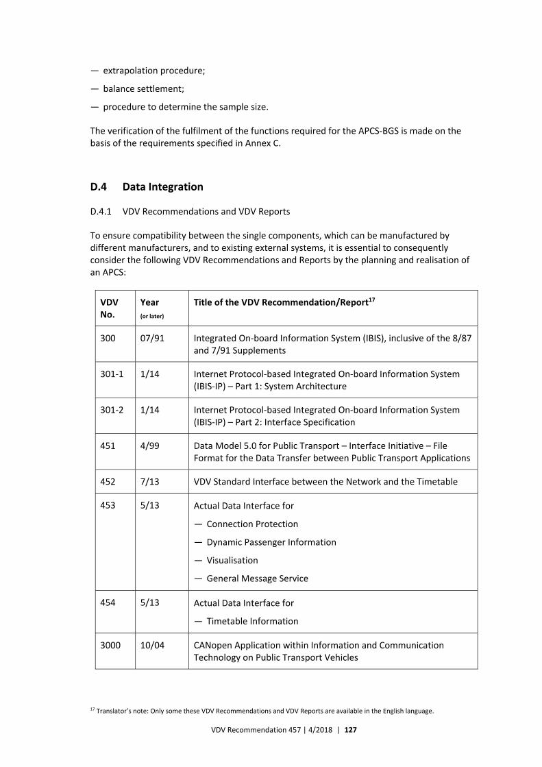
VDV Recommendation 457 | 4/2018 | 127
— extrapolation procedure;
— balance settlement;
— procedure to determine the sample size.
The verification of the fulfilment of the functions required for the APCS‐BGS is made on the basis of the requirements specified in Annex C.
D.4 Data Integration
D.4.1 VDV Recommendations and VDV Reports
To ensure compatibility between the single components, which can be manufactured by different manufacturers, and to existing external systems, it is essential to consequently consider the following VDV Recommendations and Reports by the planning and realisation of an APCS:
VDV No.
Year
(or later)
Title of the VDV Recommendation/Report17
300 07/91 Integrated On‐board Information System (IBIS), inclusive of the 8/87 and 7/91 Supplements
301‐1 1/14 Internet Protocol‐based Integrated On‐board Information System (IBIS‐IP) – Part 1: System Architecture
301‐2 1/14 Internet Protocol‐based Integrated On‐board Information System (IBIS‐IP) – Part 2: Interface Specification
451 4/99 Data Model 5.0 for Public Transport – Interface Initiative – File Format for the Data Transfer between Public Transport Applications
452 7/13 VDV Standard Interface between the Network and the Timetable
453 5/13 Actual Data Interface for
— Connection Protection
— Dynamic Passenger Information
— Visualisation
— General Message Service
454 5/13 Actual Data Interface for
— Timetable Information
3000 10/04 CANopen Application within Information and Communication Technology on Public Transport Vehicles
17 Translator’s note: Only some these VDV Recommendations and VDV Reports are available in the English language.
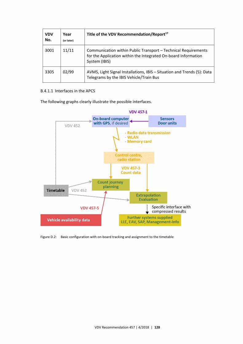
VDV Recommendation 457 | 4/2018 | 128
VDV No.
Year
(or later)
Title of the VDV Recommendation/Report17
3001 11/11 Communication within Public Transport – Technical Requirements for the Application within the Integrated On‐board Information System (IBIS)
3305 02/99 AVMS, Light Signal Installations, IBIS – Situation and Trends (5): Data Telegrams by the IBIS Vehicle/Train Bus
B.4.1.1 Interfaces in the APCS
The following graphs clearly illustrate the possible interfaces.
Figure D.2: Basic configuration with on‐board tracking and assignment to the timetable
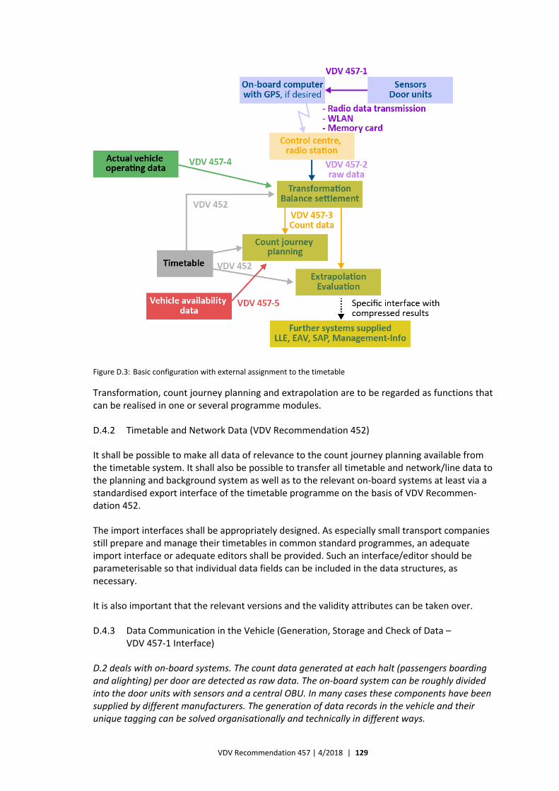
VDV Recommendation 457 | 4/2018 | 129
Figure D.3: Basic configuration with external assignment to the timetable
Transformation, count journey planning and extrapolation are to be regarded as functions that can be realised in one or several programme modules.
D.4.2 Timetable and Network Data (VDV Recommendation 452)
It shall be possible to make all data of relevance to the count journey planning available from the timetable system. It shall also be possible to transfer all timetable and network/line data to the planning and background system as well as to the relevant on‐board systems at least via a standardised export interface of the timetable programme on the basis of VDV Recommen‐dation 452.
The import interfaces shall be appropriately designed. As especially small transport companies still prepare and manage their timetables in common standard programmes, an adequate import interface or adequate editors shall be provided. Such an interface/editor should be parameterisable so that individual data fields can be included in the data structures, as necessary.
It is also important that the relevant versions and the validity attributes can be taken over.
D.4.3 Data Communication in the Vehicle (Generation, Storage and Check of Data – VDV 457‐1 Interface)
D.2 deals with on‐board systems. The count data generated at each halt (passengers boarding and alighting) per door are detected as raw data. The on‐board system can be roughly divided into the door units with sensors and a central OBU. In many cases these components have been supplied by different manufacturers. The generation of data records in the vehicle and their unique tagging can be solved organisationally and technically in different ways.
VDV Recommendation 457 | 4/2018 | 130
It is important that the data structures are unambiguously determined. It is a condition for the exchange of data between on‐board systems from different manufacturers.
This interface between the sensors/door units and the central OBU is described in detail in E.1.
The interface makes it possible to connect sensors to the OBU, which is necessary if either the OBU or the sensors were available beforehand or if either of them is to be renewed or modified. Moreover, it makes it possible to combine a new OBU and new sensors from different manufacturers. In E.1 the minimum requirements for the contents in addition to the requirements specified in VDV Recommendations 300 and 301 are defined (e.g. query intervals, status messages) to allow later diagnoses in the downstream systems.
The APC‐OBU can take over the transformation task, which is usually assigned to the background system. The degree of on‐board tagging of the count data can vary much. The complete data records are either generated directly in the vehicle, buffered and passed on to the background system or completed in the background system. The former has the disadvantage that big data volumes have to be stored in the vehicles and transferred.
Depending on the selected transfer technology, the raw data (primary data) or data records have to be buffered in the vehicle. The memory size depends on the intended technical transmission method and the reserve to be defined, which is to prevent loss of data if it is not always possible to transfer data to the background or management system for operational or technical reasons.
All recorded data shall be transferred to the background system, which makes the plausibility check. The status of the on‐board passenger counting system shall also be registered and transferred together with the count data. Optionally, it should be available as a current fault signal. Reference is made to Figure 13, which shows the basic structure of a process chain.
D.4.4 Transfer of Data from the APC‐OBU to a Control Centre/Radio Station (VDV 457‐2 Interface)
By the transmission of data from the vehicle to the control centre distinction is made between use of:
— the existing AVMS/ITCS infrastructure for the supply and transmission of data;
— autonomous data transmission systems.
The transmission itself can take place in accordance with the technical procedure described in D.2.5.
The VDV 457‐2 interface is at the point of transmission of raw count data to the background system.
This interface is important if the background system and the on‐board system have been supplied by different manufacturers. From a long‐term point of view, it is also important for an all‐inclusive (original) solution to ensure its exchangeability and upgrading later. Therefore, it is recommended always to plan and require such an interface.
This interface is at the point at which the data are output by the vehicle and merged in a central server. The mobile telecommunications can expressly take place in proprietary formats or be encrypted. The data collection (radio) station is assigned to the on‐board system and shall provide the raw data of the counting system in a VDV interface format so that they can be
VDV Recommendation 457 | 4/2018 | 131
processed by the background system. The processing is needed by both the operative part of the background system and the evaluation software (inclusive of the extrapolation). In this connection it is important to point out that the fault messages have to remain in the raw data.
By analogy to the two basic concepts of on‐board systems, i.e. the vehicle concept and the train concept, there are two instances, i.e. an instance in which the raw data have already been tracked (line/course/stops are considered to be known, perhaps identified via the index) and an instance in which the data are merely recorded and enhanced by e.g. GPS coordinates.
This information supports the transformation, the evaluation, the plausibility check and the correction of data records as well as the balance settlement and the calibration (of e.g. the distance pulses). Moreover, it includes important facts on the reliability of the APCS. Finally, criteria that can lead to rejection of count journeys and to individual checks (preventive or corrective maintenance) can be derived from the single pieces of information.
This interface between the central on‐board unit and the background systems is described in detail in E.2.
D.4.5 Interfaces in the Background System (VDV 457‐3 Interface)
The so‐called background system includes several functions, which can be offered separately and combined as desired, i.e.:
— count journey planning;
— transformation;
— balance settlement;
— sample check;
— extrapolation;
— evaluation.
Often extrapolation software and evaluation software are already being used, and a further or new counting system is to be connected as an additional data supplier. Then an interface is needed for the processed and plausibility‐checked count data. Count data are transferred per stop and journey in the correct journey order.
Thus, there is a further interface within the background system, i.e. the VDV 457‐3 interface, which is described in detail in E.3.
This interface is needed for the exchange of count data that have been transformed and checked for plausibility and the balance of which has already been settled. It does not include system‐specific status messages. The vehicle, the line, the journey and the stop are known, and – if desired – the count data are specific to a single door.
This interface can also be used to enter manual count data (hardcopy or handheld) into an evaluation system. It shall always be possible for the user to enter the count data per vehicle, per door and per coach class. It is important that persons who remain seated are registered at the end points. Moreover, the detected actual times (arrival and departure) for each stop should be included. It should be possible to detect dropped stops, which are stops with identical actual arrival and departure times.
VDV Recommendation 457 | 4/2018 | 132
The actual vehicle type or the concrete vehicle number shall be included in the count data. Changes in the vehicle combination shall be detected by alternating vehicle types or added/ removed vehicles. Additional optional data fields per stop can include further attributes likes faults and quality factors.
D.4.6 Actual Vehicle Operating Data Interface (VDV 457‐4 Interface)
It has turned out to be practical to perform transformations on the basis of the timetable data, i.e. the actual operating data of the vehicles. This aspect is important because a transformation quote is recommended. The VDV 457‐4 interface (see E.4) has been defined for the transfer of these data to the background system.
D.4.7 Vehicle Availability Data Interface (VDV 457‐5 Interface)
By the application of the count journey planning tool information about the availability of the vehicles equipped with APCSs is needed to plan the operation of the counting vehicles. It is an obvious choice to transfer these data from existing external systems (e.g. a depot management system). The VDV 457‐5 interface has been defined for the transfer of these data to the background system (see E.5).
D.4.8 Further Possible Interfaces
To transfer aggregated passenger counting results to downstream systems, e.g. the reporting system, the controlling system, the revenue‐sharing system, the system concerning supplier's long‐term declarations, management information systems, SAP planning systems and ticket check systems, further interfaces might be needed.
Interfaces that export data from the background system shall be based on general standards and be an integral part of the requirements specification.
D.4.9 Data Management and Administration
Operating data shall be managed and administered in accordance with commercial principles. The following shall be considered:
— all detected count data shall remain in the system and shall not be modified;
— unambiguous access rights shall be awarded;
— only authorised persons may reject or delete data;
— unintended deletion of data shall be prevented by the system, e.g. wastebasket system or inactive data;
— count data shall be stored in a database in a time‐ and spatially structured way;
— backup shall be made.
D.4.10 Transfer of Legacy Data
Transfer of legacy data means transfer of data from legacy background systems. If existing background systems are replaced by new ones, these new systems shall have a parameterisable import interface, via which the legacy data can be transferred. In this connection attention shall especially be paid to the VDV Recommendations and VDV Reports listed in D.4.1 and to common databases.
VDV Recommendation 457 | 4/2018 | 133
These legacy data shall be stored in the new system in a time‐ and spatially structured way and be available for evaluations.
D.4.11 Formats
The formats for interface data should be so selected that they are
— independent of the operating system (text files);
— flexible as regards the contents (keywords, no fixed format);
— easy to expand (self‐writing with keywords);
— easy to process.
Moreover, they should be orientated towards the common standards. Especially CSV and XML formats that fulfil all requirements are suitable.
D.4.12 Special Radio Data Transmission Features
It is justified to have doubts about the data security at vehicle – server interfaces realised by mobile telecommunications or radio data transmission if transparent data formats are used. Transparent formats like XML also generate much data overhead, which is a time factor by radio data transmission. The following two solutions can put things right:
— encryption and lossless compression of the transparent data;
— transmission of the data in proprietary binary formats (manufacturer‐specific, non‐public, non‐human‐readable).
If proprietary transmission formats are applied, the radio units on the vehicle and the server, respectively, make up a closed system. Therefore, it is important to consider the following:
— radio data transmission shall not be a limiting factor as regards the data contents to be transmitted, i.e. in principle it shall be possible to transmit all the information to be included in the VDV 457‐2 interface and no single fields should be filtered out;
— when the vehicle has received the binary data, the server shall make the decrypted CSV or XML data, which have been coded in accordance with the VDV 457‐2 interface, available.
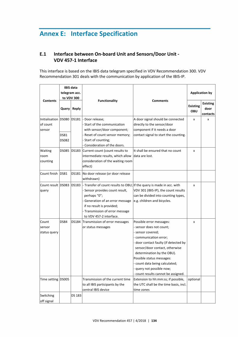
VDV Recommendation 457 | 4/2018 | 134
Annex E: Interface Specification
E.1 Interface between On‐board Unit and Sensors/Door Unit ‐ VDV 457‐1 Interface
This interface is based on the IBIS data telegram specified in VDV Recommendation 300. VDV Recommendation 301 deals with the communication by application of the IBIS‐IP.
Contents
IBIS data
telegram acc.
to VDV 300 Functionality Comments
Application by
Query Reply Existing
OBU
Existing
door
contacts
Initialisation
of count
sensor
DS080
DS181 ‐ Door release;
‐ Start of the communication
with sensor/door component;
‐ Reset of count sensor memory;
‐ Start of counting;
‐ Consideration of the doors.
A door signal should be connected
directly to the sensor/door
component if it needs a door
contact signal to start the counting.
x x
DS81
DS082
Waiting
room
counting
DS085 DS183 Current count (count results to
intermediate results, which allow
consideration of the waiting room
effect)
It shall be ensured that no count
data are lost.
x
Count finish DS81 DS181 No door release (or door release
withdrawn)
Count result
query
DS083
DS183 ‐ Transfer of count results to OBU;
‐ Sensor provides count result,
perhaps “0”;
‐ Generation of an error message
if no result is provided;
‐ Transmission of error message
to VDV 457‐2 interface.
If the query is made in acc. with
VDV 301 (IBIS‐IP), the count results
can be divided into counting types,
e.g. children and bicycles.
x
Count
sensor
status query
DS84 DS184 Transmission of error messages
or status messages
Possible error messages:
‐ sensor does not count;
‐ sensor covered;
‐ communication error;
‐ door contact faulty (if detected by
sensor/door contact, otherwise
determination by the OBU).
Possible status messages:
‐ count data being calculated;
‐ query not possible now;
‐ count results cannot be assigned.
x
Time setting DS005 Transmission of the current time
to all IBIS participants by the
central IBIS device
Extension to hh:mm:ss; if possible,
the UTC shall be the time basis, incl.
time zones
optional
Switching
off signal
DS 183
VDV Recommendation 457 | 4/2018 | 135
Note: The switching off signal event is described in the framework specification (Annex D). The OBU interrogates
the sensors/door components in accordance with the IBIS communication specified in VDV Recommendation 300
x seconds before the switching off.
E.1.1 Examples of Queries and Replies
OBU interrogates the sensor for “preparation of passenger counting” via the VDV 300 data record ID DS80a Situation: Door was opened or released for passenger actuation Sensor reply to the OBU with the VDV 300 data record ID DS181 as confirmation _____________________________________________________________________ OBU interrogates the sensor for “performance of passenger counting” via the VDV 300 data record ID DS81a Situation: Door is closed Sensor reply to the OBU with the VDV 300 data record ID DS181 as confirmation _____________________________________________________________________ OBU interrogates the sensor for “vehicle driving” via the VDV 300 data record ID DS82a Situation: Vehicle is driving, wheel sensor pulse has given the relevant signal Sensor reply to the OBU with the VDV 300 data record ID DS181 as confirmation _____________________________________________________________________ OBU interrogates the sensor for “delivery of result” via the VDV 300 data record ID DS83a Sensor reply to the OBU: — If the status of the sensor is Z=1 (new result available), the sensor replies with the VDV 300
data record ID DS183 as confirmation. — In all other cases the sensor does not reply. _____________________________________________________________________ OBU interrogates the sensor for “mentioning device status” via the VDV 300 data record ID DS84a (DS84a is not specified in VDV 300, but is a quasi‐standard by manufacturers of sensors and OBUs) Sensor reply to the OBU with the VDV 300 data record ID DS184 as confirmation _____________________________________________________________________ OBU interrogates the sensor for “switching off signal” via the VDV 300 data record ID DS84a (DS84a is not specified in VDV 300). This data record is sent by the central IBIS device to signal to the sensors that the operating voltage is switched off in about 10 seconds. Sensor reply to the OBU with the VDV 300 data record ID DS181 as confirmation _______________________________________________________________________ OBU interrogates the sensor for “time setting” via the VDV 300 data record ID DS005 This data record is sent by the central IBIS device to set the time in devices. The sensor does not send a reply to the OBU upon receipt of this data record because it can be sent to several devices simultaneously.
As regards the communication via the ethernet reference is made to VDV Recommen‐dation 301 on IBIS‐IP.
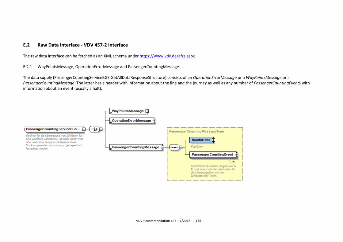
VDV Recommendation 457 | 4/2018 | 136
E.2 Raw Data Interface ‐ VDV 457‐2 Interface
The raw data interface can be fetched as an XML schema under https://www.vdv.de/afzs.aspx.
E.2.1 WayPointsMessage, OperationErrorMessage and PassengerCountingMessage
The data supply (PassengerCountingServiceBGS.GetAllDataResponseStructure) consists of an OperationErrorMessage or a WayPointsMessage or a PassengerCountingMessage. The latter has a header with information about the line and the journey as well as any number of PassengerCountingEvents with information about an event (usually a halt).
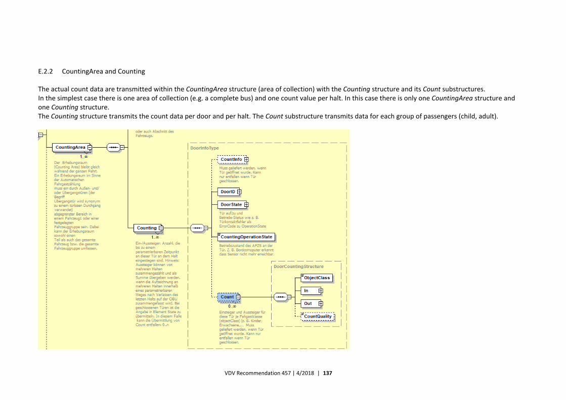
VDV Recommendation 457 | 4/2018 | 137
E.2.2 CountingArea and Counting
The actual count data are transmitted within the CountingArea structure (area of collection) with the Counting structure and its Count substructures. In the simplest case there is one area of collection (e.g. a complete bus) and one count value per halt. In this case there is only one CountingArea structure and one Counting structure. The Counting structure transmits the count data per door and per halt. The Count substructure transmits data for each group of passengers (child, adult).
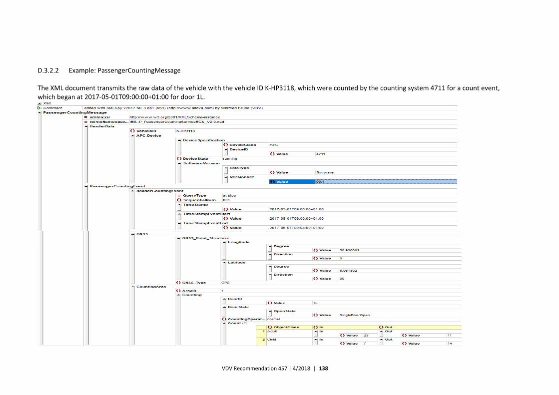
VDV Recommendation 457 | 4/2018 | 138
D.3.2.2 Example: PassengerCountingMessage
The XML document transmits the raw data of the vehicle with the vehicle ID K‐HP3118, which were counted by the counting system 4711 for a count event, which began at 2017‐05‐01T09:00:00+01:00 for door 1L.
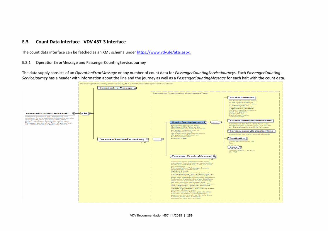
VDV Recommendation 457 | 4/2018 | 139
E.3 Count Data Interface ‐ VDV 457‐3 Interface
The count data interface can be fetched as an XML schema under https://www.vdv.de/afzs.aspx.
E.3.1 OperationErrorMessage and PassengerCountingServiceJourney
The data supply consists of an OperationErrorMessage or any number of count data for PassengerCountingServiceJourneys. Each PassengerCounting‐ServiceJourney has a header with information about the line and the journey as well as a PassengerCountingMessage for each halt with the count data.
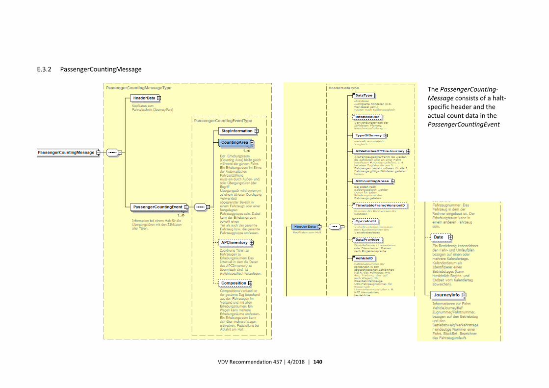
VDV Recommendation 457 | 4/2018 | 140
E.3.2 PassengerCountingMessage
The PassengerCounting‐Message consists of a halt‐specific header and the actual count data in the PassengerCountingEvent
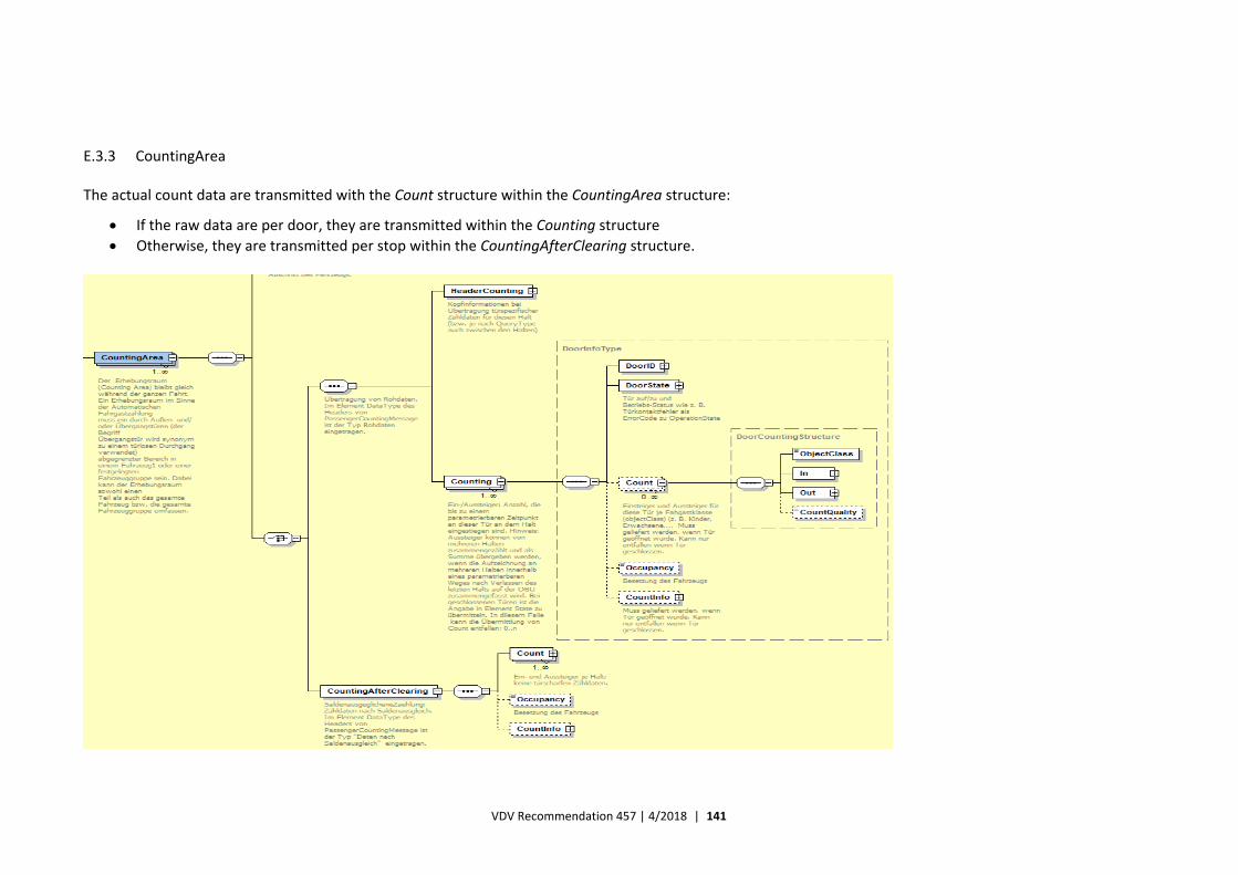
VDV Recommendation 457 | 4/2018 | 141
E.3.3 CountingArea
The actual count data are transmitted with the Count structure within the CountingArea structure:
If the raw data are per door, they are transmitted within the Counting structure
Otherwise, they are transmitted per stop within the CountingAfterClearing structure.
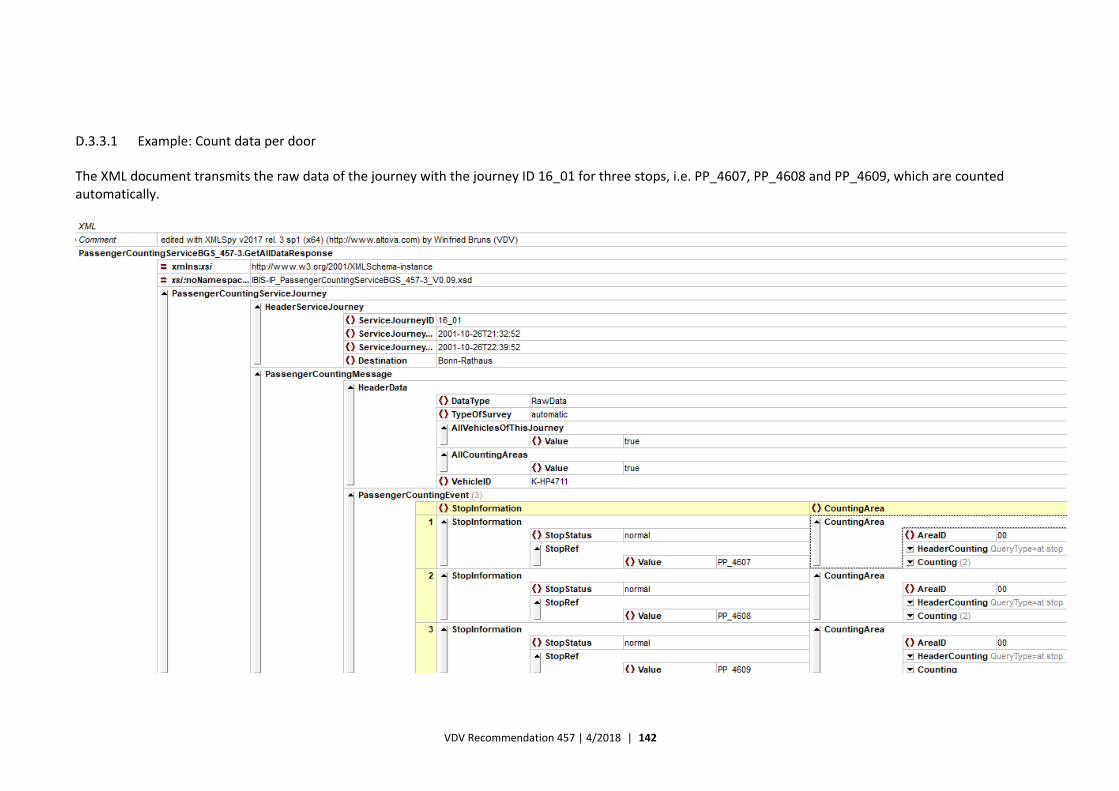
VDV Recommendation 457 | 4/2018 | 142
D.3.3.1 Example: Count data per door
The XML document transmits the raw data of the journey with the journey ID 16_01 for three stops, i.e. PP_4607, PP_4608 and PP_4609, which are counted automatically.
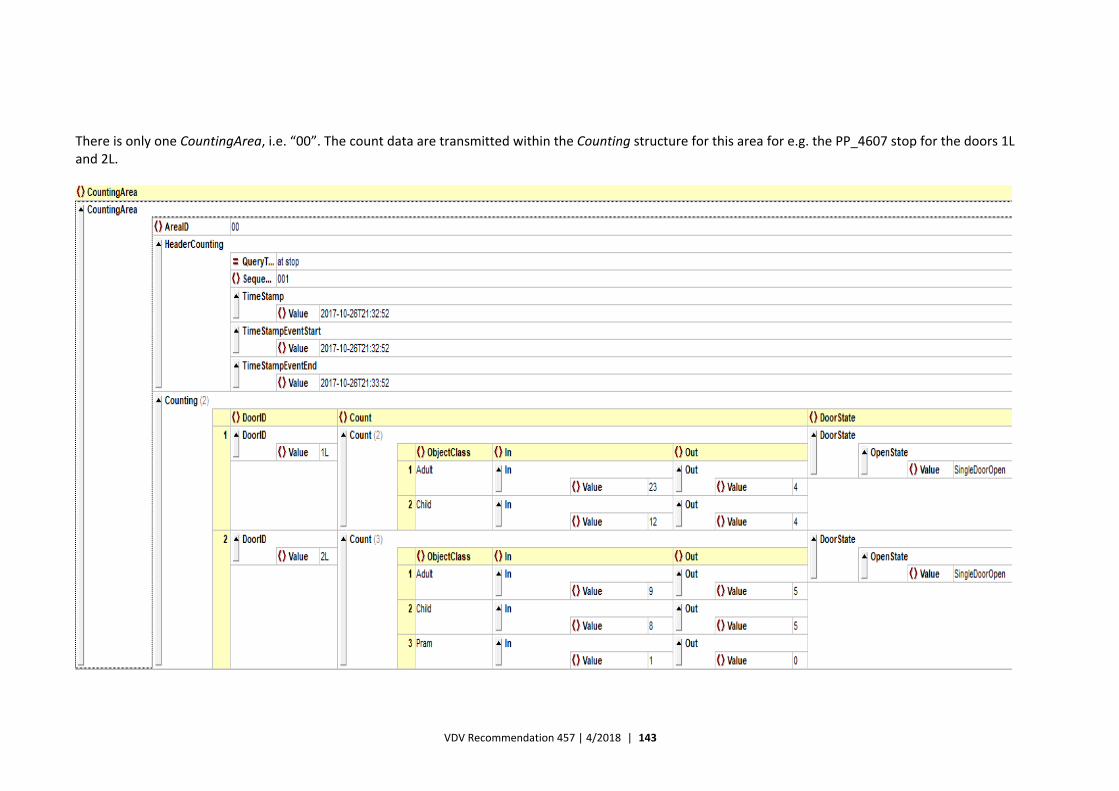
VDV Recommendation 457 | 4/2018 | 143
There is only one CountingArea, i.e. “00”. The count data are transmitted within the Counting structure for this area for e.g. the PP_4607 stop for the doors 1L and 2L.
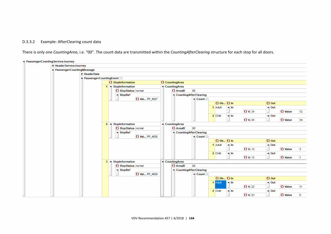
VDV Recommendation 457 | 4/2018 | 144
D.3.3.2 Example: AfterClearing count data
There is only one CountingArea, i.e. “00”. The count data are transmitted within the CountingAfterClearing structure for each stop for all doors.
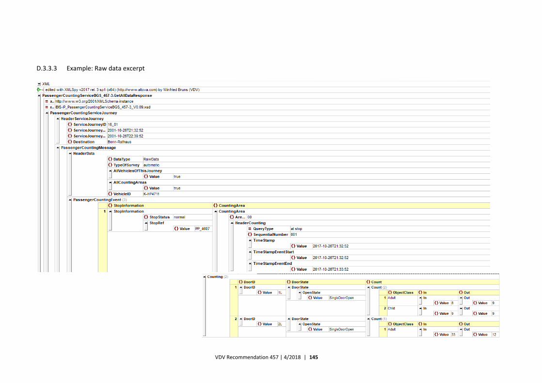
VDV Recommendation 457 | 4/2018 | 145
D.3.3.3 Example: Raw data excerpt
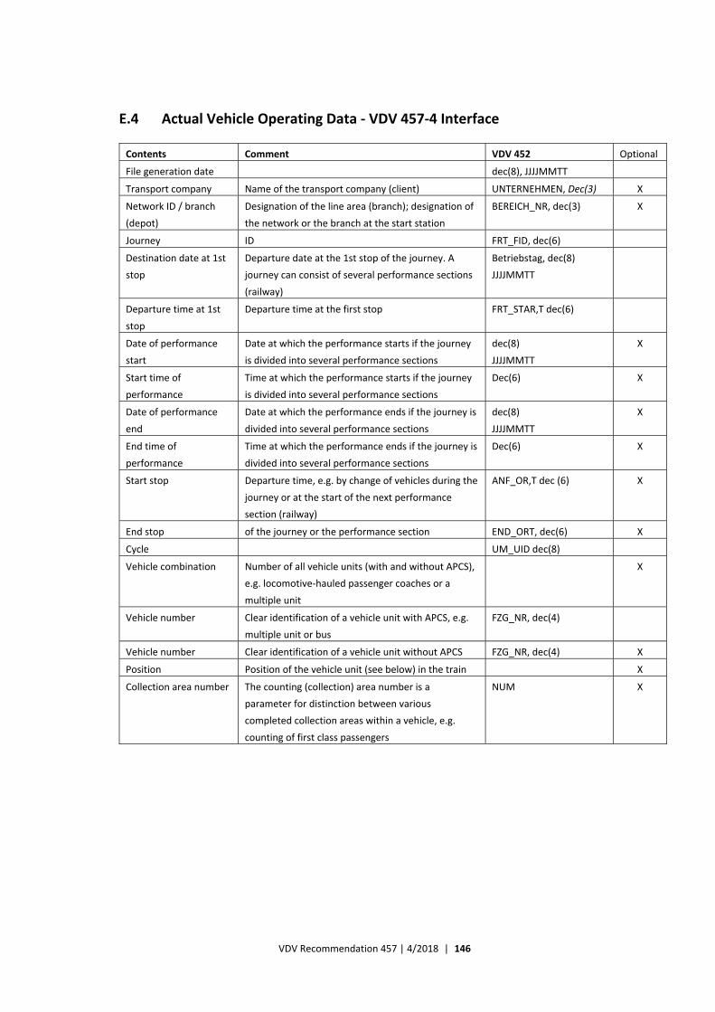
VDV Recommendation 457 | 4/2018 | 146
E.4 Actual Vehicle Operating Data ‐ VDV 457‐4 Interface
Contents Comment VDV 452 Optional
File generation date dec(8), JJJJMMTT
Transport company Name of the transport company (client) UNTERNEHMEN, Dec(3) X
Network ID / branch
(depot)
Designation of the line area (branch); designation of
the network or the branch at the start station
BEREICH_NR, dec(3) X
Journey ID FRT_FID, dec(6)
Destination date at 1st
stop
Departure date at the 1st stop of the journey. A
journey can consist of several performance sections
(railway)
Betriebstag, dec(8)
JJJJMMTT
Departure time at 1st
stop
Departure time at the first stop FRT_STAR,T dec(6)
Date of performance
start
Date at which the performance starts if the journey
is divided into several performance sections
dec(8)
JJJJMMTT
X
Start time of
performance
Time at which the performance starts if the journey
is divided into several performance sections
Dec(6) X
Date of performance
end
Date at which the performance ends if the journey is
divided into several performance sections
dec(8)
JJJJMMTT
X
End time of
performance
Time at which the performance ends if the journey is
divided into several performance sections
Dec(6) X
Start stop Departure time, e.g. by change of vehicles during the
journey or at the start of the next performance
section (railway)
ANF_OR,T dec (6) X
End stop of the journey or the performance section END_ORT, dec(6) X
Cycle UM_UID dec(8)
Vehicle combination Number of all vehicle units (with and without APCS),
e.g. locomotive‐hauled passenger coaches or a
multiple unit
X
Vehicle number Clear identification of a vehicle unit with APCS, e.g.
multiple unit or bus
FZG_NR, dec(4)
Vehicle number Clear identification of a vehicle unit without APCS FZG_NR, dec(4) X
Position Position of the vehicle unit (see below) in the train X
Collection area number The counting (collection) area number is a
parameter for distinction between various
completed collection areas within a vehicle, e.g.
counting of first class passengers
NUM X
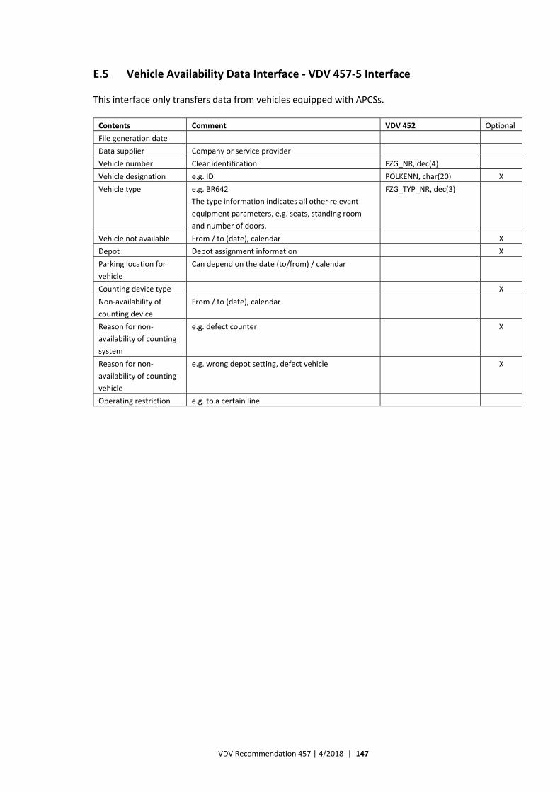
VDV Recommendation 457 | 4/2018 | 147
E.5 Vehicle Availability Data Interface ‐ VDV 457‐5 Interface
This interface only transfers data from vehicles equipped with APCSs.
Contents Comment VDV 452 Optional
File generation date
Data supplier Company or service provider
Vehicle number Clear identification FZG_NR, dec(4)
Vehicle designation e.g. ID POLKENN, char(20) X
Vehicle type e.g. BR642
The type information indicates all other relevant
equipment parameters, e.g. seats, standing room
and number of doors.
FZG_TYP_NR, dec(3)
Vehicle not available From / to (date), calendar X
Depot Depot assignment information X
Parking location for
vehicle
Can depend on the date (to/from) / calendar
Counting device type X
Non‐availability of
counting device
From / to (date), calendar
Reason for non‐
availability of counting
system
e.g. defect counter X
Reason for non‐
availability of counting
vehicle
e.g. wrong depot setting, defect vehicle X
Operating restriction e.g. to a certain line
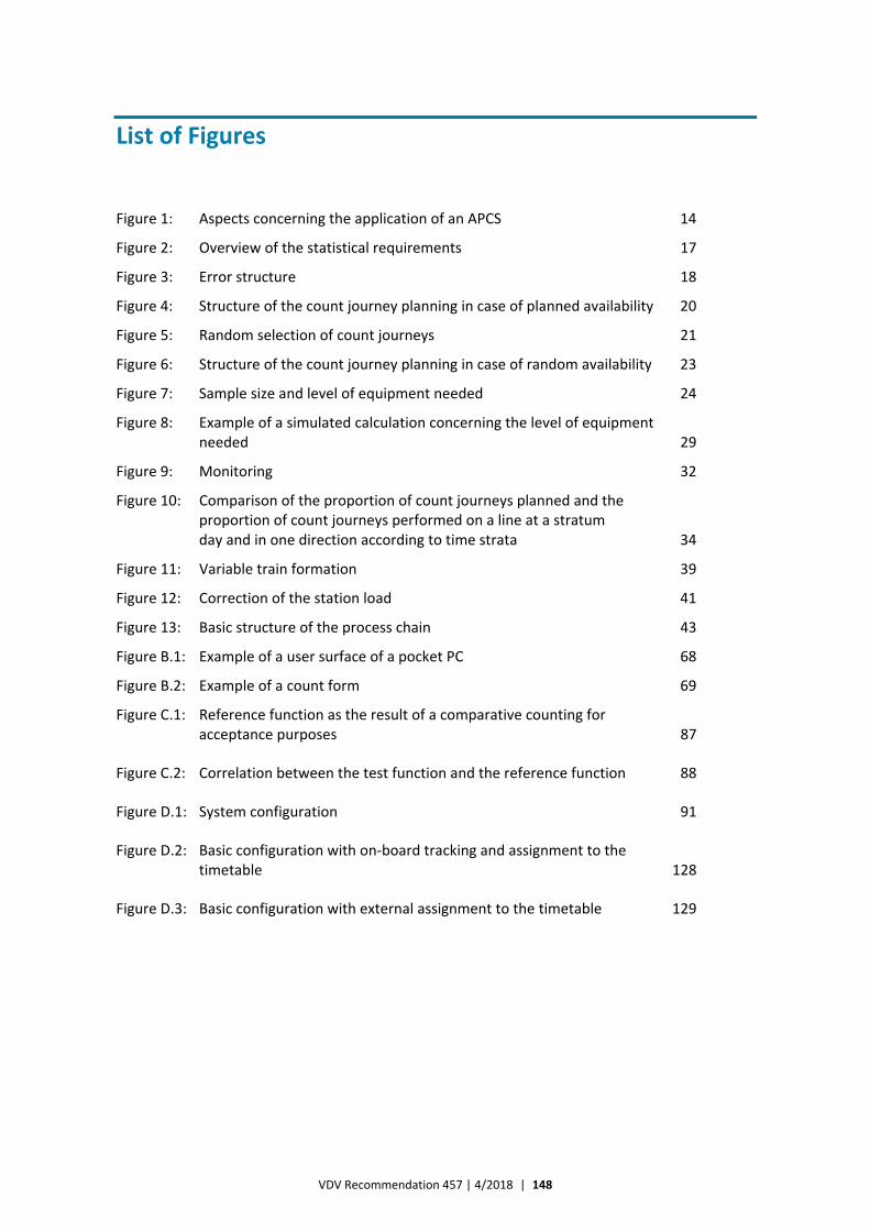
VDV Recommendation 457 | 4/2018 | 148
List of Figures
Figure 1: Aspects concerning the application of an APCS 14
Figure 2: Overview of the statistical requirements 17
Figure 3: Error structure 18
Figure 4: Structure of the count journey planning in case of planned availability 20
Figure 5: Random selection of count journeys 21
Figure 6: Structure of the count journey planning in case of random availability 23
Figure 7: Sample size and level of equipment needed 24
Figure 8: Example of a simulated calculation concerning the level of equipment needed 29
Figure 9: Monitoring 32
Figure 10: Comparison of the proportion of count journeys planned and the proportion of count journeys performed on a line at a stratum day and in one direction according to time strata 34
Figure 11: Variable train formation 39
Figure 12: Correction of the station load 41
Figure 13: Basic structure of the process chain 43
Figure B.1: Example of a user surface of a pocket PC 68
Figure B.2: Example of a count form 69
Figure C.1: Reference function as the result of a comparative counting for acceptance purposes 87
Figure C.2: Correlation between the test function and the reference function 88
Figure D.1: System configuration 91
Figure D.2: Basic configuration with on‐board tracking and assignment to the timetable 128
Figure D.3: Basic configuration with external assignment to the timetable 129

VDV Recommendation 457 | 4/2018 | 149
Imprint
Verband Deutscher Verkehrsunternehmen e. V. (VDV) Kamekestr. 37‐39 ∙ 50672 Cologne ∙ Germany T +49 (0)221 57979‐0 ∙ F +49 (0)221 57979‐8000 [email protected] ∙ www.vdv.de
Contact
Winfried Bruns T 49 (0)221 57979‐120 F 49 (0)221 57979‐8120 [email protected]

Verband Deutscher Verkehrsunternehmen e. V. (VDV) Kamekestr. 37‐39 ∙ 50672 Cologne ∙ Germany T +49 (0)221 57979‐0 ∙ F +49 (0)221 57979‐8000 [email protected] ∙ www.vdv.de