VDOT GOVERNANCE DOCUMENT CONSTRUCTION MANUAL CONSTRUCTION ... · PDF filevdot governance...
349
VDOT GOVERNANCE DOCUMENT CONSTRUCTION MANUAL CONSTRUCTION DIVISION REVISED MAY 2016
Transcript of VDOT GOVERNANCE DOCUMENT CONSTRUCTION MANUAL CONSTRUCTION ... · PDF filevdot governance...

VDOT GOVERNANCE DOCUMENT
CONSTRUCTION MANUAL
CONSTRUCTION DIVISION
REVISED MAY 2016
VIRGINIA
DEPARTMENT OF TRANSPORTATION
i
Introduction
This Manual has been prepared to inform and assist construction inspection personnel in
the performance of their duties and in the documentation of project activities. This is not
a specification document and its content is not legally binding upon any Department
contract and should be recognized as a guide only. References to certain sections of
the Specifications appear throughout in order to relate certain inspection activities to
an applicable Specification.
Recognizing that any manual of this type must undergo continuous revisions, each
recipient is requested to submit suggested changes through appropriate channels to the
Scheduling and Contract Division. Approved changes, additions, or deletions will be
issued as the need arises. Each recipient of the Manual is responsible for keeping the
contents of their copy up to date.
This Construction Manual is presented with the sincere belief that it will aid in
maintaining the high quality construction standards which have been established over the
years by the Department.
August 2004 (revised May 2016)
ii
Table of Contents
GENERAL ........................................................................................................................ 1
County, City and Town Codes ........................................................................................ 2
COUNTIES ................................................................................................................ 3
CITIES AND TOWNS .............................................................................................. 6
Field Organization of the Department ......................................................................... 12
Area Construction Engineer ..................................................................................... 13
Distinguishing Features of this Position .............................................................. 13
Examples of Duties of this Position ......................................................................... 13
Construction Manager .............................................................................................. 15
Distinguishing Features of this Position .............................................................. 15
Examples of Duties of this Position ..................................................................... 15
Inspector Senior ....................................................................................................... 16
Distinguishing Features of this Position .............................................................. 16
Examples of Duties of this Position ..................................................................... 16
Inspector ................................................................................................................... 17
Distinguishing Features of this Position .............................................................. 17
Examples of Duties of this Position ..................................................................... 17
Inspector Trainee ...................................................................................................... 19
Distinguishing Features of this Position .............................................................. 19
Examples of Duties of this Position ..................................................................... 19
Federal Highway Administration and United States Department of Transportation ... 20
Ethical Conduct ............................................................................................................ 21
Integrity .................................................................................................................... 21
Hatch Act ................................................................................................................. 21
Title 5 (Section 118K) HATCH ACT ............................................... 21
Public Relations ........................................................................................................... 23
General ..................................................................................................................... 23
Contractor-Inspector Relations ................................................................................ 23
GENERAL PROVISIONS ........................................................................................... 25
General Provisions ....................................................................................................... 26
Award and Execution of Contracts .......................................................................... 26
Pre-Construction Conference ................................................................................... 26
Progress Schedule and Plan of Operations .............................................................. 28
Section 104 – Scope of Work ...................................................................................... 30
Section 104.04 Maintenance During Construction .................................................. 30
Section 104.04(d) Delays ..................................................................................... 30
Section 104.04(e) Connections and Entrances ..................................................... 31
Section 104.04(f) Grading Operations ................................................................. 32
Section 104.05(a) Signs ....................................................................................... 32
Section 104.06 Cleanup ....................................................................................... 32
Section 105 – Control of Work .................................................................................... 34
iii
Section 105.02 Plans and Working Drawings .......................................................... 34
Section 105.03 Conformity with Plans and Specifications ...................................... 34
Section 105.05 Coordination of Plans, Standard Drawings, Specifications,
Supplemental Specifications, Special Provisions, and Special Provision Copied Notes
................................................................................................................................... 35
Section 105.11 Authority and Duties of Inspector ................................................... 35
Section 105.13 Removal of Unacceptable and Unauthorized Work ........................ 35
Section 105.15 Acceptance ...................................................................................... 36
Section 105.16 Submission and Disposition of Claims ........................................... 37
Section 106 – Control of Material ................................................................................ 38
General ..................................................................................................................... 38
Section 106.03 Local Material Sources (Pits and Quarries) .................................... 39
Section 106.05 Rights for and Use of Materials Found on the Project .................... 40
Section 106.08 Storing Materials ............................................................................. 41
Section 107 – Legal Relations and Responsibilities to the Public ............................... 42
Storm Water Pollution Prevention (SWPP) Plan ..................................................... 42
Contractor SWPP Plans ....................................................................................... 43
Changes and Deficiencies .................................................................................... 43
Section 107.08 Railway-Highway Provisions ......................................................... 43
Section 107.10 Barricades and Warning Signs ........................................................ 43
Section 107.11 Use of Explosives ........................................................................... 45
Section 107.14 Environmental Stipulations ............................................................. 46
Erosion and Siltation Control ............................................................................... 46
Pollution ............................................................................................................... 47
Section 108 – Prosecution and Progress of Work ........................................................ 48
Section 108.09 Determination and Extension of Contract Time Limit ................... 48
Suspension of Work Due to Fault of Contractor .................................................. 49
SECTION 109 - MEASUREMENT AND PAYMENT .............................................. 50
Section 109.01 Measurement of Quantities ............................................................. 50
Scales ................................................................................................................... 50
Accuracy of Measurement for Payment ............................................................... 50
Section 109.05 Extra and Force Account Work ...................................................... 51
Work Orders ......................................................................................................... 52
Section 109.06 Eliminated Items ............................................................................. 54
Section 109.07 Partial Payments .............................................................................. 55
Withholding of Estimate ...................................................................................... 56
Section 109.08 Payment for Material on Hand ........................................................ 58
Section 109.09 - Final Payment ............................................................................... 58
SECTION 110 - MISCELLANEOUS PROVISIONS ................................................. 60
Section 110.01 Common Carrier Rates .................................................................... 60
Section 110.02 Labor and Wages ............................................................................ 60
1. Posters .......................................................................................................... 61
2. Interviews of Contractor's Employees ......................................................... 61
3. Statement of Compliance - Form C-56 ........................................................ 61
4. Payrolls ........................................................................................................ 61
5. Payroll Information ...................................................................................... 62
iv
6. Corrections ................................................................................................... 63
7. Other Requirements ..................................................................................... 63
8. Violations ..................................................................................................... 63
9. Determining Wage Classification ................................................................ 63
10. Convict Labor On Federal-Aid Projects .................................................. 64
Section 110.03 Equal Employment Opportunity ..................................................... 64
Equal Employment Opportunity Actions and Documentations ........................... 64
Section 110.04 Use of Disadvantaged and Minority Business Enterprises (DBE and
MBE) ........................................................................................................................ 67
Section 110.05 Construction Safety and Health Standards ...................................... 68
Section 110.06 Bulletin Boards and the Posting of Official Notices ....................... 68
Required Notices and Posters .............................................................................. 68
Fraud Poster - Form C-58 .................................................................................... 69
Wage Rates Information Poster - Form C-59 and Wage Rates ............................ 69
MATERIALS ............................................................................................................... 70
Section 200 – Materials ................................................................................................ 71
General ..................................................................................................................... 71
Inspector Certifications ............................................................................................ 72
Minimum Acceptance Sampling Requirements ....................................................... 72
Density Testing Requirements ................................................................................. 72
Materials Division Intranet/Internet Links ............................................................... 73
ROADWAY CONSTRUCTION ................................................................................. 74
Section 301 – Clearing and Grubbing .......................................................................... 75
Excavation Areas ..................................................................................................... 75
Embankment Areas .................................................................................................. 75
Disposal of Combustible Materials .......................................................................... 76
Disposal of Material Outside the Right-Of-Way ..................................................... 76
Disposal of Firewood ............................................................................................... 76
Measurement and Payment ...................................................................................... 77
Inspector's Checklist ................................................................................................ 77
Section 302 – Drainage Structures ............................................................................... 78
General ..................................................................................................................... 78
Foundation and Bedding .......................................................................................... 78
Pipe Installation ........................................................................................................ 79
Backfill ..................................................................................................................... 79
Method of Measurement .......................................................................................... 80
Inspector's Checklist for Pipe ................................................................................... 80
Box Culverts ............................................................................................................ 80
Location of Structure ........................................................................................... 81
Excavation and Foundation Exploration .............................................................. 81
Forming ................................................................................................................ 81
Reinforcing Steel .................................................................................................. 81
Mixing and Placing Concrete ............................................................................... 82
Removal of Forms .................................................................................................... 82
Box Culvert Header Forms Removal ................................................................... 82
Backfilling ............................................................................................................ 83
v
Records ................................................................................................................ 83
Inspector's Checklist for Box Culverts ..................................................................... 83
Section 303 - Excavation and Earthwork ................................................................. 85
Description ............................................................................................................... 85
Erosion and Siltation Control ................................................................................... 85
Earth Berms and Slope Drains ............................................................................. 85
Incremental Seeding ............................................................................................. 85
Check Dams ......................................................................................................... 86
Baled Straw Silt Barriers ...................................................................................... 86
Temporary Silt Fences, Geotextile Fabric Silt Fences, and Filter Barriers .......... 86
Definitions of Terms ................................................................................................ 87
Removal of Unsuitable Materials ............................................................................ 89
Embankments ........................................................................................................... 90
Earth Embankments ............................................................................................. 90
Rock Embankments ................................................................................................. 92
Hydraulic Embankment ........................................................................................... 92
Disposal of Surplus Materials .................................................................................. 93
Tolerances ................................................................................................................ 93
Inspector’s Checklist ................................................................................................ 94
Section 304 – Constructing Density Control Strips ..................................................... 95
General ..................................................................................................................... 95
Tolerances ................................................................................................................ 95
Roadways ............................................................................................................. 95
Aggregate Shoulders ............................................................................................ 96
Asphalt Shoulders ................................................................................................ 96
Section 305 – Subgrade and Shoulders ........................................................................ 97
Shaping and Compacting the Subgrade ................................................................... 97
Finishing Subgrade .................................................................................................. 98
Shoulders .................................................................................................................. 98
A. Prime Coat ................................................................................................... 98
B. Asphalt Surface Treatment ........................................................................... 98
C. Asphalt Concrete Shoulder .......................................................................... 98
Method of Payment .................................................................................................. 99
Inspector's Checklist ................................................................................................ 99
Section 306 – Lime Stabilization ............................................................................... 100
Description ............................................................................................................. 100
Placement Limitations ............................................................................................ 100
Preparation of Roadbed .......................................................................................... 100
Application of Lime ............................................................................................... 100
Mixing .................................................................................................................... 101
Compaction and Finishing ..................................................................................... 101
Protection and Curing ............................................................................................ 102
Method of Measurement ........................................................................................ 102
Inspector's Checklist .............................................................................................. 102
Section 307 - Hydraulic Cement Stabilization ........................................................... 103
Description ............................................................................................................. 103
vi
Weather Limitations ............................................................................................... 103
Materials ................................................................................................................ 103
Preparation of Existing Surface ............................................................................. 104
Application ............................................................................................................. 104
Compacting and Finishing ..................................................................................... 105
Construction Joints ................................................................................................. 105
Protecting and Curing ............................................................................................ 105
Method of Measurement ........................................................................................ 106
Inspector's Checklist .............................................................................................. 106
SECTION 308 - SUBBASE COURSE ...................................................................... 107
Description ............................................................................................................. 107
Construction Methods ............................................................................................ 107
Method of Measurement ........................................................................................ 108
Inspector's Checklist .............................................................................................. 108
SECTION 309 - AGGREGATE BASE COURSE .................................................... 109
Materials ................................................................................................................ 109
Sampling and Testing ............................................................................................ 109
Construction Methods ............................................................................................ 109
Method of Measurement ........................................................................................ 110
Inspector's Checklist .............................................................................................. 110
Section 310 – Tack Coat ............................................................................................ 111
Description ............................................................................................................. 111
Method of Measurement ........................................................................................ 111
Inspector's Checklist .............................................................................................. 111
Section 311 - Prime Coat ........................................................................................... 112
Description ............................................................................................................. 112
Materials ................................................................................................................ 112
Construction ........................................................................................................... 113
Measurement and Payment .................................................................................... 115
Inspector's Checklist .............................................................................................. 115
SECTION 312 - SEAL COAT ................................................................................... 116
Description ............................................................................................................. 116
Materials ................................................................................................................ 116
Weather Limitations ............................................................................................... 116
Equipment .............................................................................................................. 116
Construction Methods ............................................................................................ 117
Project Records ...................................................................................................... 118
Basis of Payment .................................................................................................... 119
Inspector’s Checklist .............................................................................................. 119
SECTION 313 - ASPHALT SURFACE TREATMENT .......................................... 120
General ................................................................................................................... 120
Materials ................................................................................................................ 120
Procedures .............................................................................................................. 120
Inspector's Checklist .............................................................................................. 120
SECTION 315 - ASPHALT CONCRETE PAVEMENT .......................................... 122
Description ............................................................................................................. 122
vii
Placement Limitations ............................................................................................ 122
Cold Weather Paving Limitations ...................................................................... 124
Equipment .......................................................................................................... 125
Hauling Equipment ............................................................................................ 125
Asphalt Concrete Paving Machines ................................................................... 125
Rollers ................................................................................................................ 126
Miscellaneous Tools .......................................................................................... 126
Conditioning of Existing Surface ....................................................................... 126
Spreading and Finishing ........................................................................................ 128
A. Wavy Surface (Short Choppy Waves) ....................................................... 128
B. Wavy Surface (Long Waves) ..................................................................... 128
C. Excessively Open Surface Texture ............................................................ 128
D. Varying Surface Texture ............................................................................ 128
E. Bleeding Patches on Surface ...................................................................... 129
F. Irregular Rough Spots in Pavement ........................................................... 129
Compaction ............................................................................................................ 131
Inspector's Checklist .............................................................................................. 133
SECTION 316 - HYDRAULIC CEMENT CONCRETE PAVEMENT ................... 136
Description ............................................................................................................. 136
Materials ................................................................................................................ 136
Equipment .............................................................................................................. 137
Setting Forms ......................................................................................................... 138
Conditioning of Subgrade or Subbase Course ....................................................... 138
Concrete Pavement - Slip Form Method ................................................................ 140
Test Specimens ...................................................................................................... 140
Strike-Off of Concrete and Placement of Reinforcement ...................................... 141
Joints ...................................................................................................................... 141
Dowel Supporting Assemblies ........................................................................... 141
Tiebars ................................................................................................................ 142
Tie Bolts ............................................................................................................. 142
Sawing ................................................................................................................ 142
Final Strike-Off, Consolidation and Finishing ....................................................... 142
Station Numbers and Dates .................................................................................... 143
Curing .................................................................................................................... 144
Surface Test ........................................................................................................... 144
Removing Forms .................................................................................................... 144
Sealing Joints ......................................................................................................... 145
Protection of Pavement .......................................................................................... 145
Checking Finished Grade and Cross Slope .................................................... 145
Tolerance in Pavement Thickness .......................................................................... 145
Basis of Payment .................................................................................................... 145
Inspector's Checklist .............................................................................................. 147
BRIDGES AND STRUCTURES .............................................................................. 150
Section 401 - Structure Excavation ............................................................................ 151
Description ............................................................................................................. 151
Preparation of Foundations For Footings ............................................................... 151
viii
Cofferdams and Shoring ........................................................................................ 152
Backfill Material .................................................................................................... 152
Placement ............................................................................................................... 153
Backfilling Weepholes ........................................................................................... 153
Records .................................................................................................................. 154
Inspector's Checklist .............................................................................................. 154
Section 403 – Bearing Piles ....................................................................................... 156
Description ............................................................................................................. 156
Suitability of Foundation ....................................................................................... 157
Test Piles vs. Production Piles ............................................................................... 157
Order Lists ............................................................................................................. 158
Methods Used to Estimate Bearing Pile Bearing Capacities ................................. 158
Glossary of Terms .................................................................................................. 161
Estimating the Stroke ............................................................................................. 166
Preparation Prior to Pile Driving ........................................................................... 167
Observations During Pile Driving .......................................................................... 168
Additional Considerations ..................................................................................... 169
Preboring ............................................................................................................ 169
Jetting ................................................................................................................. 169
Unusual Driving ................................................................................................. 169
Accuracy of Driving .......................................................................................... 170
Inspector’s Checklist .............................................................................................. 173
Hammer List .......................................................................................................... 174
Section 404 - Hydraulic Cement Concrete Operations .............................................. 182
General ................................................................................................................... 182
Materials ................................................................................................................ 182
Forms ..................................................................................................................... 182
Placement and Consolidation ................................................................................. 182
Construction Joints ................................................................................................. 182
Bonding Construction Joints .................................................................................. 183
Removal of Forms and Construction of Superimposed Elements ......................... 183
Curing of Concrete ................................................................................................. 183
Bridge Deck Curing ........................................................................................... 184
Protection of Concrete ........................................................................................... 184
Hot Weather Concrete Placement .......................................................................... 184
Expansion and Fixed Joints ................................................................................... 185
Bearing Areas ......................................................................................................... 186
Finishing Concrete Surfaces .................................................................................. 186
Inspector's Checklist .............................................................................................. 188
SECTION 405 - PRESTRESSED CONCRETE ........................................................ 190
Description ............................................................................................................. 190
Handling, Storage and Erection ............................................................................. 190
Tolerances .............................................................................................................. 190
Inspector's Checklist .............................................................................................. 191
Section 406 – Reinforcing Steel ................................................................................. 192
Description ............................................................................................................. 192

ix
Protection of Material ............................................................................................ 192
Placing and Fastening ............................................................................................ 192
Splicing and Lapping ............................................................................................. 193
Inspector's Checklist .............................................................................................. 194
SECTION 407 - STEEL STRUCTURES .................................................................. 195
Materials ................................................................................................................ 195
Shop Drawings ....................................................................................................... 195
Welds ..................................................................................................................... 195
Drifting of Holes .................................................................................................... 198
High-Strength Bolts ............................................................................................... 198
Alignment at Bearings and Transverse Connections ............................................. 199
Handling and Storing Materials ............................................................................. 199
Inspector's Checklist .............................................................................................. 199
Section 410 – Railings and Parapets .......................................................................... 202
Description ............................................................................................................. 202
Metal Railing ......................................................................................................... 202
Concrete Railing and Parapet ................................................................................. 202
Method of Measurement ........................................................................................ 203
Inspector’s Checklist .............................................................................................. 203
SECTION 411 - PROTECTIVE COATING OF METAL IN STRUCTURES ......... 204
General ................................................................................................................... 204
Materials ................................................................................................................ 204
Certifications .......................................................................................................... 204
Procedures .............................................................................................................. 205
Surface Preparation ............................................................................................ 205
Application of Coating ....................................................................................... 205
Quality Control .................................................................................................. 207
Contractor's Record Keeping ............................................................................. 207
Environmental Protection ...................................................................................... 207
Environmental Plan ............................................................................................ 207
Monitoring ......................................................................................................... 207
Storage and Disposal of Waste Material ............................................................ 207
Health and Safety Plan ....................................................................................... 208
Inspector's Checklist .............................................................................................. 208
SECTION 412 – WIDENING, REPAIRING, AND RECONSTRUCTING EXISTING
STRUCTURES .......................................................................................................... 210
Description ............................................................................................................. 210
Procedures .............................................................................................................. 210
Bridge Superstructure Repairs ............................................................................... 210
Bridge Deck Overlay Repairs ................................................................................ 211
Latex or Silica Fume Overlay ............................................................................ 212
Bridge Substructure Repairs .................................................................................. 213
Shotcrete ................................................................................................................ 213
Inspector's Checklist .............................................................................................. 217
SECTION 414 - RIPRAP .......................................................................................... 219
General ................................................................................................................... 219
x
Stockpiled Dry Riprap ........................................................................................... 220
Procedures .............................................................................................................. 221
Mortared Riprap ..................................................................................................... 221
Grouted Riprap ....................................................................................................... 222
Inspector's Checklist .............................................................................................. 222
Section 415 – Concrete Slope Protection ................................................................... 223
General ................................................................................................................... 223
Method of Measurement ........................................................................................ 223
Inspector’s Checklist .............................................................................................. 224
SECTION 419 - BRIDGE CONDUIT SYSTEMS AND LIGHTING SYSTEMS ... 225
Description ............................................................................................................. 225
Materials ................................................................................................................ 225
Installation .............................................................................................................. 225
Inspector's Checklist .............................................................................................. 226
INCIDENTAL CONSTRUCTION ........................................................................... 227
Section 501 – Underdrains ......................................................................................... 228
Description ............................................................................................................. 228
Installation .............................................................................................................. 228
Method of Measurement ........................................................................................ 228
Inspector’s Checklist .............................................................................................. 229
Section 502 – Incidental Concrete Items ................................................................... 230
General ................................................................................................................... 230
Procedures .............................................................................................................. 230
Inspector’s Checklist .............................................................................................. 232
Section 503 – Right-of-Way Monuments .................................................................. 234
General ................................................................................................................... 234
Method of Measurement ........................................................................................ 234
Section 504 – Sidewalks, Steps and Handrails .......................................................... 235
Sidewalks ............................................................................................................... 235
Steps ....................................................................................................................... 236
Handrails ................................................................................................................ 236
Inspector’s Checklist .............................................................................................. 236
Section 505 – Guardrail and Median Barrier ............................................................. 238
General ................................................................................................................... 238
Method of Measurement ........................................................................................ 238
Inspector’s Checklist .............................................................................................. 239
Section 507 – Fences ................................................................................................. 241
Construction Methods ............................................................................................ 241
Method of Measurement ........................................................................................ 242
Inspector’s Checklist .............................................................................................. 242
Section 508 – Demolition of Pavement And Obscuring Roadway ............................ 243
Description ............................................................................................................. 243
Method of Measurement ........................................................................................ 243
Section 509 – Patching Hydraulic Cement Concrete Pavement ................................ 244
Method of Measurement ........................................................................................ 244
xi
Inspector's Checklist .............................................................................................. 244
Section 511 – Allaying Dust ...................................................................................... 246
General ................................................................................................................... 246
Inspector’s Checklist .............................................................................................. 246
Section 512 – Maintaining Traffic ............................................................................. 247
General ................................................................................................................... 247
Inspector’s Checklist .............................................................................................. 250
Construction Pavement Markings .......................................................................... 250
Construction Pavement Markers ............................................................................ 251
Impact Attenuators ................................................................................................. 252
Temporary Signalization ........................................................................................ 252
Traffic Barrier Service ........................................................................................... 253
Inspector’s Checklist .............................................................................................. 253
Section 515 – Planing Pavement ................................................................................ 255
General ................................................................................................................... 255
Method of Measurement ........................................................................................ 255
Inspector’s Checklist .............................................................................................. 255
Section 516 – Demolition of Buildings and Clearing Parcels ................................... 256
Measurement and Payment .................................................................................... 256
SECTION 519 - SOUND BARRIER WALLS .......................................................... 257
Procedures .............................................................................................................. 257
Precast Sound Barrier Wall ................................................................................ 257
Metal Sound Barrier Wall .................................................................................. 257
Method of Measurement ........................................................................................ 258
Inspector's Checklist .............................................................................................. 258
ROADSIDE DEVELOPMENT ................................................................................. 259
Section 601 – Selective Tree Removal, Trimming, and Cleanup .............................. 260
General ................................................................................................................... 260
Measurement and Payment .................................................................................... 260
Section 602 - Topsoil ................................................................................................. 261
General ................................................................................................................... 261
Construction Methods ............................................................................................ 261
Preparation of Subsoil ........................................................................................ 261
Handling and Placing Topsoil ............................................................................ 261
Depth .................................................................................................................. 261
Seeding ............................................................................................................... 261
Method of Measurement ........................................................................................ 262
Section 603 - Seeding ................................................................................................ 263
Description ............................................................................................................. 263
Procedures .............................................................................................................. 263
Drainage ............................................................................................................. 263
Application of Lime ........................................................................................... 263
Fertilizer ............................................................................................................. 263
Sowing Seed ....................................................................................................... 264
Seeding on Stabilized Shoulders ........................................................................ 265
xii
Temporary Seeding ............................................................................................ 265
Method of Measurement ........................................................................................ 266
Section 604-Sodding .................................................................................................. 267
General ................................................................................................................... 267
Preparing Sod Beds ................................................................................................ 267
Placing Sod ............................................................................................................ 267
Method of Measurement ........................................................................................ 267
Section 605 - Planting ................................................................................................ 268
General ................................................................................................................... 268
Materials ................................................................................................................ 268
Planting Seasons .................................................................................................... 268
Storage ................................................................................................................... 268
Planting .................................................................................................................. 269
Staking and Guying ................................................................................................ 269
Staking ............................................................................................................... 269
Guying ................................................................................................................ 270
Pruning ................................................................................................................... 270
Period of Establishment ......................................................................................... 270
Guarantee ............................................................................................................... 270
Method of Measurement ........................................................................................ 271
Wetland Mitigation Construction ............................................................................... 271
General ................................................................................................................... 271
Coordination .......................................................................................................... 272
Project Showings ................................................................................................ 272
Pre-Construction Conference ............................................................................. 272
Source of Materials ............................................................................................ 272
Commencement of Construction ....................................................................... 273
Plan Changes ...................................................................................................... 273
Requests for Substitutions .................................................................................. 273
Confirmation of Subgrade Elevations ................................................................ 273
Confirmation of Final Grade .............................................................................. 274
Disturbances of Approved Final Grades ............................................................ 274
Hydrologic Monitoring Devices ........................................................................ 274
Pre-planting Hydrologic Monitoring ................................................................. 274
Plant Material Inspection ................................................................................... 275
Planting Inspection ............................................................................................. 275
Establishment Period ......................................................................................... 275
Final Planting / Mitigation Site Inspection ........................................................ 276
INSPECTOR'S CHECKLIST FOR WETLAND MITIGATION SITES .............. 277
Section 606 – Soil Retention Coverings .................................................................... 279
General ................................................................................................................... 279
Construction ........................................................................................................... 279
Method of Measurement ........................................................................................ 279
Inspector’s Checklist .............................................................................................. 279
Section 607 – Herbicide Spraying ............................................................................. 281
General ................................................................................................................... 281
xiii
Application ............................................................................................................. 281
Method of Measurement ........................................................................................ 281
Section 608 – Mowing ............................................................................................... 282
General ................................................................................................................... 282
Method of Measurement ........................................................................................ 282
TRAFFIC CONTROL DEVICES ............................................................................. 283
SECTION 700 - GENERAL ...................................................................................... 284
Description ............................................................................................................. 284
Working Drawings ................................................................................................. 284
Procedures .............................................................................................................. 284
Grounding .......................................................................................................... 284
Foundation ......................................................................................................... 284
Erection of Poles, Post and Sign Structures ....................................................... 285
Conductor Cables ............................................................................................... 285
Conduit Systems ................................................................................................ 286
Electrical Service ............................................................................................... 286
Inspector’s Checklist .............................................................................................. 287
Section 701 – Traffic Signs ........................................................................................ 288
General ................................................................................................................... 288
Materials ................................................................................................................ 288
Procedures .............................................................................................................. 288
Fabrication ......................................................................................................... 288
Transporting and Storing ................................................................................... 288
Erection .............................................................................................................. 289
Method of Measurement ........................................................................................ 289
Inspector’s Checklist .............................................................................................. 289
SECTION 702 – DELINEATORS ............................................................................ 291
General ................................................................................................................... 291
Procedures .............................................................................................................. 291
Method of Measurement ........................................................................................ 291
Inspectors Checklist ............................................................................................... 291
SECTION 703 – TRAFFIC SIGNALS ..................................................................... 292
General ................................................................................................................... 292
Equipment .............................................................................................................. 292
Prosecution of Work .............................................................................................. 292
Equipment Color .................................................................................................... 292
Mounting Controller Cabinets ............................................................................... 293
Installing Signal Heads .......................................................................................... 293
Rigging Details ...................................................................................................... 294
Testing Equipment ................................................................................................. 294
Method of Measurement ........................................................................................ 294
Inspector's Checklist .............................................................................................. 294
Section 704 – Pavement Markings and Markers ....................................................... 296
General ................................................................................................................... 296
Materials ................................................................................................................ 296

xiv
Pavement Markings ................................................................................................ 296
Pavement Markers ................................................................................................. 297
Snow-plowable Raised Pavement Markers ........................................................ 297
Raised Pavement Markers .................................................................................. 298
Method of Measurement ........................................................................................ 298
Inspector’s Checklist .............................................................................................. 298
APPENDIX A .............................................................................................................. 300
Department Equipment .............................................................................................. 300
Engineering Equipment .......................................................................................... 300
Vehicular Equipment ............................................................................................. 301
Publications ............................................................................................................ 302
WEB Sites .............................................................................................................. 302
APPENDIX B .............................................................................................................. 304
Terms for Subgrade and Pavement Structures ........................................................... 304
General ................................................................................................................... 304
1. Figure: B-2 Location of Subgrade and Pavement Structure Courses ........ 305
APPENDIX C .............................................................................................................. 306
Project Records .......................................................................................................... 306
General ................................................................................................................... 306
Accuracy ............................................................................................................ 306
Clarity ................................................................................................................ 306
Legibility ............................................................................................................ 306
Completeness ..................................................................................................... 306
Self Checking ..................................................................................................... 307
Project Diary .......................................................................................................... 308
Inspector’s Daily Report ........................................................................................ 309
State Force Operations ........................................................................................... 310
1. Plans ........................................................................................................... 310
2. FHWA Approval ........................................................................................ 311
3. Detailed Estimate ....................................................................................... 311
4. Diary and Summary ................................................................................... 311
5. Cost Keeping Records ................................................................................ 311
6. Exceptions .................................................................................................. 312
APPENDIX D .............................................................................................................. 313
Road and Bridge Stakeout ......................................................................................... 313
General ................................................................................................................... 313
Slope Stakes ........................................................................................................... 313
Fine Grade Stakes .................................................................................................. 313
Bridge Stakeouts .................................................................................................... 314
2. 3 Survey Stake Marking ............................................................................. 315
3. Figure: D-4 Slope Stakes on Tangent ........................................................ 316
Project Inspector's Responsibilities - Bridge Stakeout .......................................... 317
xv
Project Inspector’s Responsibilities- Box Culvert Stakeout .................................. 317
Use of Instruments ................................................................................................. 317
Transit ................................................................................................................ 317
Levels ................................................................................................................. 318
Chaining ............................................................................................................. 320
Checking Plan Dimensions and Elevations ........................................................... 318
Vertical Curve ........................................................................................................ 321
4. Figure: Vertical Curve ............................................................................... 321
Circular Curves ...................................................................................................... 323
5. Figure: Circular Curve Drawing ................................................................ 325
6. Figure: Reverse Curve Drawing ................................................................ 325
APPENDIX E .............................................................................................................. 329
Safety Rules ........................................................................................................... 329
Construction and Maintenance .............................................................................. 329
General ................................................................................................................... 331

1
GENERAL

2
COUNTY, CITY AND TOWN CODES
The Commonwealth of Virginia was originally sub-divided into 100 counties. A coding
system has been developed in which the counties are given a 2 digit number from 00 to 99,
and cities and towns have a 3 digit number from 100 to 350. This coding system is used to
identify counties, cities, and towns in the project numbers. Counties are grouped together
into Districts according to their geographical location.
There are Nine Districts
l. Bristol
2. Salem
3. Lynchburg
4. Richmond
5. Hampton Roads
6. Fredericksburg
7. Culpeper
8. Staunton
9. Northern Virginia

3
COUNTIES
County Code County District
00
Arlington
Northern Virginia
01 Accomack Hampton Roads
02 Albemarle Culpeper
03 Alleghany Staunton
04 Amelia Richmond
05 Amherst Lynchburg
06 Appomattox Lynchburg
07 Augusta Staunton
08 Bath Staunton
09 Bedford Salem
10 Bland Bristol
11 Botetourt Salem
12 Brunswick Richmond
13 Buchanan Bristol
14 Buckingham Lynchburg
15 Campbell Lynchburg
16 Caroline Fredericksburg
17 Carroll Salem
18 Charles City Richmond
19 Charlotte Lynchburg
20 Chesterfield Richmond
21 Clarke Staunton
22 Craig Salem 23 Culpeper Culpeper
24 Cumberland Lynchburg
25 Dickenson Bristol
26 Dinwiddie Richmond
28 Essex Fredericksburg
29 Fairfax Northern Virginia
30 Fauquier Culpeper
31 Floyd Salem
32 Fluvanna Culpeper
33 Franklin Salem
34 Frederick Staunton
35 Giles Salem
36 Gloucester Fredericksburg
37 Goochland Richmond
38 Grayson Bristol
39 Greene Culpeper
40 Greensville Hampton Roads
41 Halifax Lynchburg
42 Hanover Richmond

4
43 Henrico Richmond
44 Henry Salem
45 Highland Staunton
46 Isle of Wight Hampton Roads
47 James City Hampton Roads
48 King George Fredericksburg
49 King & Queen Fredericksburg
50 King William Fredericksburg
51 Lancaster Fredericksburg
52 Lee Bristol
53 Loudoun Northern Virginia
54 Louisa Culpeper
55 Lunenburg Richmond
56 Madison Culpeper
57 Mathews Fredericksburg
58 Mecklenburg Richmond
59 Middlesex Fredericksburg
60 Montgomery Salem
62 Nelson Lynchburg
63 New Kent Richmond
65 Northampton Hampton Roads
66 Northumberland Fredericksburg
67 Nottoway Richmond
68 Orange Culpeper
69 Page Staunton
70 Patrick Salem
71 Pittsylvania Lynchburg
72 Powhatan Richmond
73 Prince Edward Lynchburg
74 Prince George Richmond
76 Prince William Northern Virginia
77 Pulaski Salem
78 Rappahannock Culpeper
79 Richmond Fredericksburg
80 Roanoke Salem
81 Rockbridge Staunton
82 Rockingham Staunton
83 Russell Bristol
84 Scott Bristol
85 Shenandoah Staunton
86 Smyth Bristol
87 Southampton Hampton Roads
88 Spotsylvania Fredericksburg
89 Stafford Fredericksburg
90 Surry Hampton Roads
91 Sussex Hampton Roads

5
92 Tazewell Bristol
93 Warren Staunton
95 Washington Bristol
96 Westmoreland Fredericksburg
97 Wise Bristol
98 Wythe Bristol
99 York Hampton Roads

6
CITIES AND TOWNS
County Code City or Town Code City or Town District
95
140
Abingdon
Bristol
01 160 Accomack Hampton Roads
12 161 Alberta Richmond
00 100 Alexandria Northern Virginia
15 162 Altavista Lynchburg
05 163 Amherst Lynchburg
97 164 Appalachia Bristol
06 165 Appomattox Lynchburg
42 166 Ashland Richmond
09 141 Bedford Salem
01 167 Belle Haven Hampton Roads
21 168 Berryville Staunton
97 101 Big Stone Gap Bristol
60 150 Blacksburg Salem
67 142 Blackstone Richmond
01 169 Bloxom Hampton Roads
92 143 Bluefield Bristol
33 170 Boones Mill Salem
16 171 Bowling Green Fredericksburg
21 172 Boyce Staunton
58 173 Boydton Richmond
87 174 Boykins Hampton Roads
87 175 Branchville Hampton Roads 82 176 Bridgewater Staunton
95 102 Bristol Bristol
82 177 Broadway Staunton
12 178 Brodnax Richmond
58 178 Brodnax Richmond
15 179 Brookneal Lynchburg
11 180 Buchanan Salem
81 103 Buena Vista Staunton
67 181 Burkeville Richmond
65 182 Cape Charles Hampton Roads
87 183 Capron Hampton Roads
92 184 Cedar Bluff Bristol
19 185 Charlotte C.H. Lynchburg
02 104 Charlottesville Culpeper
58 186 Chase City Richmond
71 187 Chatham Lynchburg
65 188 Cheriton Hampton Roads
64 131 Chesapeake Hampton Roads
86 189 Chilhowie Bristol
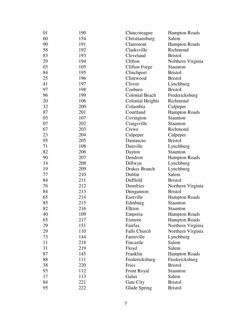
7
01 190 Chincoteague Hampton Roads
60 154 Christiansburg Salem
90 191 Claremont Hampton Roads
58 192 Clarksville Richmond
83 193 Cleveland Bristol
29 194 Clifton Northern Virginia
03 105 Clifton Forge Staunton
84 195 Clinchport Bristol
25 196 Clintwood Bristol
41 197 Clover Lynchburg
97 198 Coeburn Bristol
96 199 Colonial Beach Fredericksburg
20 106 Colonial Heights Richmond
32 200 Columbia Culpeper
87 201 Courtland Hampton Roads
03 107 Covington Staunton
07 202 Craigsville Staunton
67 203 Crewe Richmond
23 204 Culpeper Culpeper
95 205 Damascus Bristol
71 108 Danville Lynchburg
82 206 Dayton Staunton
90 207 Dendron Hampton Roads
14 208 Dillwyn Lynchburg
19 209 Drakes Branch Lynchburg
77 210 Dublin Salem
84 211 Duffield Bristol
76 212 Dumfries Northern Virginia
84 213 Dungannon Bristol
65 214 Eastville Hampton Roads
85 215 Edinburg Staunton
82 216 Elkton Staunton
40 109 Emporia Hampton Roads
65 217 Exmore Hampton Roads
29 151 Fairfax Northern Virginia
29 110 Falls Church Northern Virginia
73 144 Farmville Lynchburg
11 218 Fincastle Salem
31 219 Floyd Salem
87 145 Franklin Hampton Roads
88 111 Fredericksburg Fredericksburg
38 220 Fries Bristol
93 112 Front Royal Staunton
17 113 Galax Salem
84 221 Gate City Bristol
95 222 Glade Spring Bristol

8
81 223 Glasgow Staunton
35 224 Glen Lyn Salem
68 225 Gordonsville Culpeper
81 226 Goshen Staunton
71 227 Gretna Lynchburg
82 228 Grottoes Staunton
07 228 Grottoes Staunton
13 229 Grundy Bristol
41 230 Halifax Lynchburg
01 231 Hallwood Hampton Roads
53 232 Hamilton Northern Virginia
27 114 Hampton Hampton Roads
82 115 Harrisonburg Staunton
76 233 Haymarket Culpeper
25 234 Haysi Bristol
29 235 Herndon Northern Virginia
53 236 Hillsboro Northern Virginia
17 237 Hillsville Salem
61 238 Holland Hampton Roads
83 239 Honaker Bristol
74 116 Hopewell Richmond
71 331 Hurt Lynchburg
38 240 Independence Bristol
03 241 Iron Gate Staunton
51 242 Irvington Fredericksburg
87 243 Ivor Hampton Roads
91 244 Jarrett Hampton Roads
40 244 Jarratt Hampton Roads
52 245 Jonesville Bristol
01 246 Keller Hampton Roads
55 247 Kenbridge Richmond
19 248 Keysville Lynchburg
51 249 Kilmarnock Fredericksburg
66 249 Kilmarnock Fredericksburg
58 250 LaCrosse Richmond
12 251 Lawrenceville Richmond
83 252 Lebanon Bristol
53 253 Leesburg Northern Virginia
81 117 Lexington Staunton
54 254 Louisa Culpeper
53 255 Lovettsville Northern Virginia
69 159 Luray Staunton
15 118 Lynchburg Lynchburg
56 256 Madison Culpeper
76 155 Manassas Northern Virginia
76 152 Manassas Park Northern Virginia
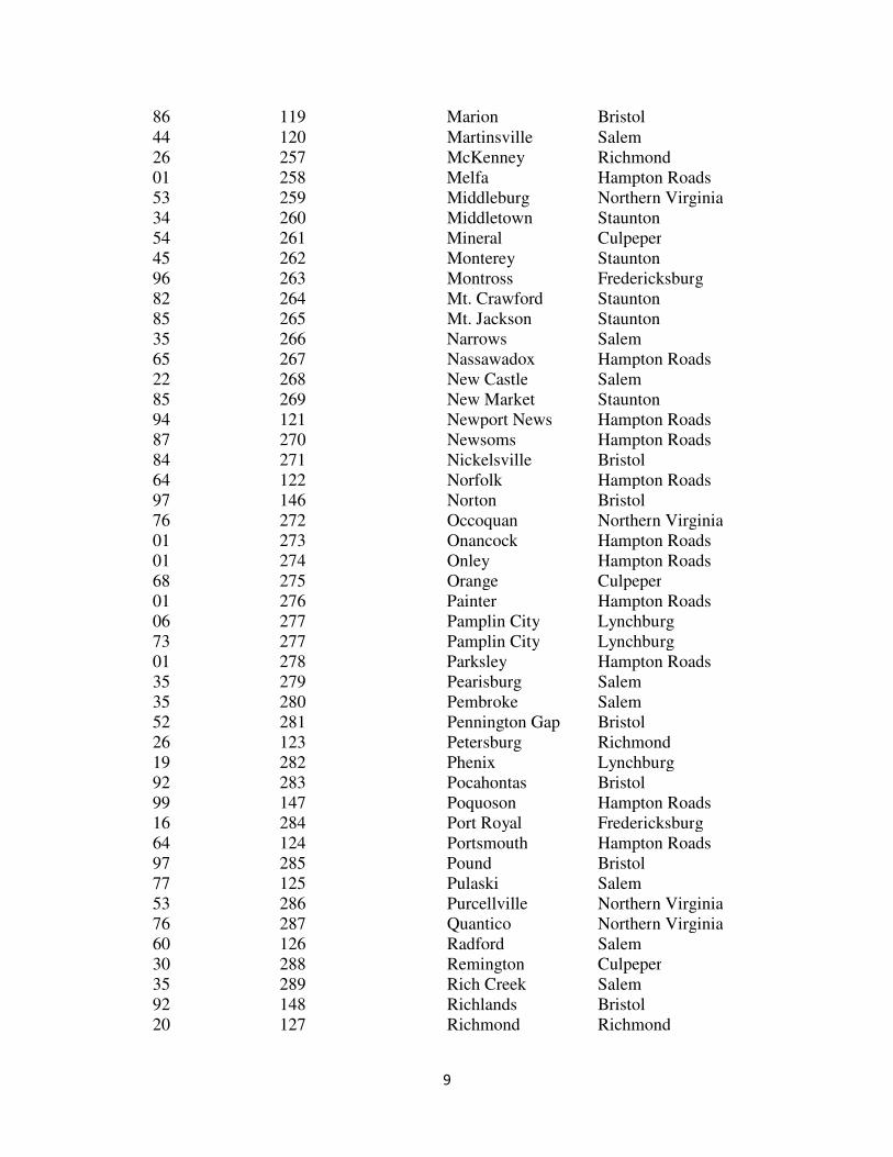
9
86 119 Marion Bristol
44 120 Martinsville Salem
26 257 McKenney Richmond
01 258 Melfa Hampton Roads
53 259 Middleburg Northern Virginia
34 260 Middletown Staunton
54 261 Mineral Culpeper
45 262 Monterey Staunton
96 263 Montross Fredericksburg
82 264 Mt. Crawford Staunton
85 265 Mt. Jackson Staunton
35 266 Narrows Salem
65 267 Nassawadox Hampton Roads
22 268 New Castle Salem
85 269 New Market Staunton
94 121 Newport News Hampton Roads
87 270 Newsoms Hampton Roads
84 271 Nickelsville Bristol
64 122 Norfolk Hampton Roads
97 146 Norton Bristol
76 272 Occoquan Northern Virginia
01 273 Onancock Hampton Roads
01 274 Onley Hampton Roads
68 275 Orange Culpeper
01 276 Painter Hampton Roads
06 277 Pamplin City Lynchburg
73 277 Pamplin City Lynchburg
01 278 Parksley Hampton Roads
35 279 Pearisburg Salem
35 280 Pembroke Salem
52 281 Pennington Gap Bristol
26 123 Petersburg Richmond
19 282 Phenix Lynchburg
92 283 Pocahontas Bristol
99 147 Poquoson Hampton Roads
16 284 Port Royal Fredericksburg
64 124 Portsmouth Hampton Roads
97 285 Pound Bristol
77 125 Pulaski Salem
53 286 Purcellville Northern Virginia
76 287 Quantico Northern Virginia
60 126 Radford Salem
30 288 Remington Culpeper
35 289 Rich Creek Salem
92 148 Richlands Bristol
20 127 Richmond Richmond
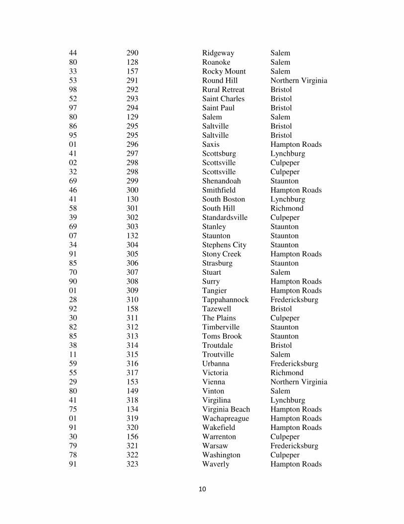
10
44 290 Ridgeway Salem
80 128 Roanoke Salem
33 157 Rocky Mount Salem
53 291 Round Hill Northern Virginia
98 292 Rural Retreat Bristol
52 293 Saint Charles Bristol
97 294 Saint Paul Bristol
80 129 Salem Salem
86 295 Saltville Bristol
95 295 Saltville Bristol
01 296 Saxis Hampton Roads
41 297 Scottsburg Lynchburg
02 298 Scottsville Culpeper
32 298 Scottsville Culpeper
69 299 Shenandoah Staunton
46 300 Smithfield Hampton Roads
41 130 South Boston Lynchburg
58 301 South Hill Richmond
39 302 Standardsville Culpeper
69 303 Stanley Staunton
07 132 Staunton Staunton
34 304 Stephens City Staunton
91 305 Stony Creek Hampton Roads
85 306 Strasburg Staunton
70 307 Stuart Salem
90 308 Surry Hampton Roads
01 309 Tangier Hampton Roads
28 310 Tappahannock Fredericksburg
92 158 Tazewell Bristol
30 311 The Plains Culpeper
82 312 Timberville Staunton
85 313 Toms Brook Staunton
38 314 Troutdale Bristol
11 315 Troutville Salem
59 316 Urbanna Fredericksburg
55 317 Victoria Richmond
29 153 Vienna Northern Virginia
80 149 Vinton Salem
41 318 Virgilina Lynchburg
75 134 Virginia Beach Hampton Roads
01 319 Wachapreague Hampton Roads
91 320 Wakefield Hampton Roads
30 156 Warrenton Culpeper
79 321 Warsaw Fredericksburg
78 322 Washington Culpeper
91 323 Waverly Hampton Roads

11
07 136 Waynesboro Staunton
84 324 Weber City Bristol
50 325 West Point Fredericksburg
51 327 White Stone Fredericksburg
47 137 Williamsburg Hampton Roads
46 328 Windsor Hampton Roads
97 329 Wise Bristol
85 330 Woodstock Staunton
98 139 Wytheville Bristol
12
FIELD ORGANIZATION OF THE DEPARTMENT The field organization of the Department is divided into nine districts. Each district is
directed by a District Administrator who is aided by two or more District Engineers and a
staff, consisting of engineers, technicians, maintenance, and administrative personnel.
The District Engineers and the staff are assigned specific responsibilities associated with
the construction and maintenance of highways located within the boundaries of the
district. The districts are sub-divided into three to six residencies which include one to
four counties, depending upon size, road mileage and other factors.
The District Construction Management organization includes the Area Construction
Engineers, Construction Managers, Contract Administrators, and Inspectors. The District
Construction Engineer is responsible to the District Administrator for the oversight of all
construction and maintenance projects in the District and has the responsibility of
determining that all construction and maintenance projects are being constructed in
compliance with the plans and Specifications. Through delegated representatives, the
District Construction Engineer provides the necessary guidance and instruction to the
Project Inspectors to achieve this end. The Area Construction Engineer periodically
inspects the project and verifies the project records. The Area Construction Engineer’s
verifications are noted in the project records. At the completion of the project the Area
Construction Engineer or duly authorized representative, inspects the Contractor's work
and notes any unfinished items. When the work is completed the Area Construction
Engineer, acting under the authority of the Chief Engineer, accepts the project.
13
Area Construction Engineer
Distinguishing Features of this Position
The A r e a C onstruction Engineer leads and guides construction inspection staff and
managers to achieve district contract goals for safety, quality, schedule, and budgeting for
construction and maintenance contracts. Provide direction, leadership, and professional
engineering advice to CM’s and inspectors and serve as responsible charge engineer for
highway construction functions.
Examples of Duties of this Position
(1) Evaluate project development process to ensure they adequately address constructability and bidability issues prior to advertisement of project. Review plans and contract special provisions prior to beginning construction work.
(2) Manage contract construction budgets for all assigned projects to meet performance goals. Coordinate with FHWA in the preparation and review of work orders, NOIs, and claims to validate necessity of work and level of federal participation.
(3) Conduct on-site field visits to ensure all elements of design and construction are within scope of contract and within established standards and specifications.
(4) Manage VDOT and consultant resources and partner with contractors to facilitate on-time completion of projects. Review, coordinate and schedule projects and monitor progress throughout construction phase. Work to resolve issues that may delay projects through partnering with all stakeholders.
(5) Provide leadership in dispute resolution; perform analyses and lead negotiations.
(6) Manage and facilitate contract and construction quality improvement. Conduct follow-up CQIP review for all correctable non-compliant questions from original review within 2 weeks of original review. Sign and distribute report to DCE, CQIP Manager and inspector of original review and project staff.
(7) Interpret plans, schedule, and contract requirements. Provide technical advice and decision to contractors, design and field staff in consultation with Engineer of Records / others. Conduct meetings with engineering and construction groups to address project issues and maintain consistency.
(8) Conduct on-site field visits and document findings to appropriate parties; perform follow-up assessments to evaluate implementation effectiveness.
(9) Discuss inspection needs with CM’s and authorize assignments of Inspectors to projects, to ensure adequate inspection coverage.
(10) Checks and approves records of work performed for final cost determination such

14
as work books and monthly estimates.
(11) Manage and ensure the training of C M ’ s a n d Inspectors, evaluates
performance, and recommends promotions and transfers.
15
Construction Manager
Distinguishing Features of this Position
The Construction Manager supervises the inspection activities on a group of highway
projects. This work involves responsibility for making assignments, supervising, and
providing technical advice to Inspectors. Emphasis is placed on the application of a
broad knowledge of field testing and inspection techniques to assure that the quality of
workmanship and materials conform with plans and Specifications and that construction
is progressing in accordance with the terms of the contract. Discussions are held with
Contractors and Inspectors and decisions are made in the field to resolve problems
requiring interpretations of Specifications and plans. Construction Managers serve as
liaison between the field and the District office to keep the Area Construction Engineer
abreast of the progress and problems on construction projects. Supervision is received
from the Area Construction Engineer through periodic discussions and the review of
reports.
Examples of Duties of this Position
(1) Determines inspection needs and assigns Inspectors to projects to ensure adequate
inspection coverage; instructs subordinates on inspection techniques and field testing
methods.
(2) Interprets contract requirements for subordinates and contractors through the analysis
of plans and Specifications.
(3) Investigates complaints from landowners arising out of conflicts between
construction and right-of-way agreements.
(4) Prepares correspondence and non-routine reports relative to the status of a project.
(5) Reviews monthly progress estimates and brings discrepancies to the attention of
Inspectors; checks and approves records of work performed for final cost
determination such as work books and monthly estimates.
(6) Maintains a perspective overview regarding federal, state, and local laws regulating
construction procedures, safety practices and working conditions.
(7) Inspects work in progress, to assure that methods, materials, and equipment conform
to approved standards.
(8) Supervises the training of Inspectors, evaluates performance, and recommends
promotions and transfers.

16
Inspector Senior
Distinguishing Features of this Position
The Inspector Senior monitors and performs all types of inspection work on both
complex and routine highway projects, or acts as a specialist and advisor to other
Inspectors on certain phases of the work requiring specialized talent and experience.
Assignments are of an independent nature and include responsibility for inspecting and
monitoring the inspection work on a complex project.
The Inspector Senior is responsible for assigning assistant Inspectors in a manner which
will assure that all phases of the work will be given adequate inspection.
Supervision is received from the Construction Manager or Area Construction Engineer
by periodic visits and reviews of records and reports. The Inspector's authority is limited
in that changes in plans and Specifications requested or recommended must be reviewed
and approved by a Construction Manager or Area Construction Engineer to whom
authority has been delegated.
Examples of Duties of this Position
(1) Inspects all phases of work on a project and advises the Contractor's superintendent or
other representative of necessary action to ensure conformance with plans, Specifications
and the contract.
(2) Inspects grading projects, paving projects, demolition projects, special design bridge
projects, signal projects, signing projects, utility projects and special projects.
(3) Reviews the performance of assistant Inspectors daily; advising them as necessary.
(4) Answers questions from assistant Inspectors and the Contractor concerning contract
requirements and their application.
(5) Reviews the "Inspector's Daily Reports" for preparation of entries for the project
diaries, as built plans, materials books, and work books.
(6) Prepares or checks construction progress reports and monthly progress estimates;
makes necessary corrections and forwards them to the Construction Manager or the Area
Construction Engineer.
(7) Performs occasionally any or all of the duties of an assistant Inspector when required
by volume of work.
(8) Monitors training of Inspectors assigned to the project.
17
Inspector
Distinguishing Features of this Position
The Inspector inspects phases of construction on a complex highway construction project
under the supervision of a Senior Inspector or independently inspects a routine highway
construction project. Assignments are of an independent or subordinate nature,
depending on the scope or complexity of the project, and are made by the Construction
Manager or Area Construction Engineer. The work is distinguished from the trainee
level by the requirements for relatively independent decisions, actions, and relationships
in dealing with Contractors or the public. Training and supervision of trainees are
responsibilities of the position.
Supervision is generally received from the Construction Manager or the Area
Construction Engineer. Considerable freedom of action is allowed and specific
instructions are required only as a result of changes in plans and Specifications,
nonconformance by a Contractor, or questions raised by the Inspector.
Examples of Duties of this Position
(1) Inspects assigned phases of work on a project and makes official contact with
Contractor's superintendent or other representative to ensure conformance with plans,
Specifications and other contract documents.
(2) Frequently checks line, grade and dimensions of roadways and structures with an
engineer's level and theodolite and advises the Contractor of any discrepancies.
(3) Checks method of construction where specific methods are stated and requires action
to correct any variance in methods employed.
(4) Ascertains that warning or directional signs are erected and maintained for the safety
and convenience of employees and the public, keeping in mind commercial and
private entrances and traffic flow.
(5) Prepares or reviews the "Inspector's Daily Reports" for preparation of entries for the
project diaries, as built plans, materials books, and other end of contract documents.
(6) Records or monitors the recording of materials received, showing quantities estimated
to be required, and quantities received, used and tested.
(7) Checks materials, or materials documents, to make sure they have been tested, or
performs routine physical tests and analysis on sample materials on the job, sends
additional samples to the District or Central Office laboratories for verification of
results.

18
(8) Prepares or checks weekly and monthly project progress reports, giving physical
progress and percent of total work completed, currently and cumulatively.
(9) Maintains accurate project records.
19
Inspector Trainee
Distinguishing Features of this Position
The Inspector Trainee performs daily assigned inspection tasks in a training capacity
preparatory to assuming the duties of an Inspector. Assignments follow a plan of on-the-
job training, the primary purpose of which is to provide experienced inspection personnel
for future highway projects. The work includes measuring, testing, and checking
materials, methods, and installations to ensure conformance by the Contractor with the
plans, specifications, and the contract. Supervisory control is intensive initially, but is
progressively decreased as knowledge of the work increases.
Examples of Duties of this Position
(1) Inspects excavations, drainage structures, road surfaces and structures to compare the
work performed with plans and Specifications, conferring frequently with higher level
Inspectors or engineering personnel to clarify or interpret details.
(2) Checks elevations against reference points using a hand level or wye level. Prepares
routine reports and records involving the application of basic geometric and
trigonometric principles. Learn use of level and transit survey instruments.
(3) Prepares an "Inspector's Daily Report" which includes the details of the Contractor's
work activities and lists the location of work, materials, equipment, and labor forces used.
(4) Becomes familiar with plans, Specifications, standards and related material when not
occupied with regular assignments or whenever so directed by higher level Inspectors.
(5) Advises Contractor's supervisory personnel of necessary actions to conform to plans
and Specifications.
(6) Assist in preparing project records.
20
FEDERAL HIGHWAY ADMINISTRATION AND
UNITED STATES DEPARTMENT OF
TRANSPORTATION
On highway projects for which part of the money is furnished by the Federal
Government, the terms of federal participation are set forth in an agreement between the
Department and the Federal Highway Administration (FHWA). Such an agreement
provides that the work is to be performed in accordance with predetermined standards
embodied in the plans and Specifications, in other approved standard drawings, and in
any special provisions necessitated by conditions peculiar to the project.
The contract for the project is awarded by the State with the concurrence of the FHWA.
Administration of the contract is a function of the Department and its Engineers and
Inspectors. However, Engineers from the FHWA may make inspections of Federal-aid
projects at times selected by them.
The relationship between the FHWA and the Department does not directly involve the
Contractor. FHWA representatives inspect the project for the purpose of reviewing the
adequacy of the Department's inspection procedure as evidenced by the prosecution of
the work in accordance with the commitments contained in the State-Federal Agreement.
The FHWA's representative has neither the responsibility nor the authority to deal
directly with the Contractor. The FHWA's representative should be advised of important
developments and changes affecting the prosecution of the work during routine visits to
the project or as necessitated by conditions.
21
ETHICAL CONDUCT
Integrity Absolute integrity on the part of Department personnel is essential if public confidence in
the Department is to be maintained. Integrity embraces everything that touches a
person's ability to do his job: resourcefulness, decisiveness, adaptability, stability, moral
courage and tenacity.
Employees of the Department must be guided in their actions by the highest of ethical
standards. Information gained through association with the Department may not be used
for personal profit or gain, nor may normal business associations with Contractors be
used to the personal advantage of an employee.
An employee of the Department is subject to dismissal if they accept gifts or gratuities
from anyone doing business with the Department. The term "gifts and gratuities"
includes, but is not limited to, monies, credits, discounts, seasonal or special occasion
presents (Christmas, birthday, weddings, etc.), edibles, drinks, household appliances and
furnishings, clothing, loans of goods or money, tickets to sporting events or theaters,
transportation, vacations, travel or hotel expenses, and any form of entertainment.
No employee of the Department shall engage in any transactions involving property
owned or controlled directly or indirectly by the Commonwealth or the Department for
personal profit, gain, or convenience.
No employee shall engage in any outside employment or business without first
submitting a request for authority to participate in such off duty activities to their
Division Administrator or District Administrator.
Any action of unethical conduct by Contractor personnel should be reported immediately
to the Construction Manager.
Hatch Act By virtue of the use of Federal-aid Funds for highway construction by the Department,
employees are subject to provisions of the Hatch Act, a Federal Law concerning political
activity. A portion is quoted below:
Title 5 (Section 118K) HATCH ACT
"No officer or employee of any State or local agency whose principal employment is in
connection with any activity which is financed in whole or in part by loans or grants
made by the United States or by any Federal agency shall (1) use his official authority or
influence for the purpose of interfering with an election or a nomination for office, or
coerce, attempt to coerce, command, or advise any other such officer or employee to pay,

22
lend or contribute any part of his salary or compensation or anything else of value to any
party, committee, organization, agency, or person for political purposes. No such official
or employee shall take any active part in political purposes. No such official or employee
shall take any active part in political management or in political campaigns. All such
persons shall retain the right to vote as they may choose and to express their opinions on
all political subjects and candidates."
23
PUBLIC RELATIONS
General
Courtesy and consideration are necessary in all contacts with the public because the
entire Department is judged by the actions of its employees. Although employees may
not obligate the Department to any course of action or any expense without due
authorization, they should always be as tactful and helpful as conditions permit. The
media of communication with the public are many: newspapers, radio, television, service
clubs, Chambers of Commerce, city and county officials, and direct contact with
individuals.
The Inspector is not authorized to release official information to any news media. The
Inspector should tactfully refer such queries to the Construction Manager. As the
authorized representative of the Department, the Construction Manager may or may not
release the information. The Construction Manager may refer the matter to the Public
Affairs Office. In either case, the media should get the most factual information
available.
In dealing with residents along the project, the Project Inspector must endeavor to
maintain friendly relations. Frequently, requests will be made on which he will not have
authority to act. In such case the Inspector must make every effort not to offend people
making these requests. The Inspector should advise such parties that they will discuss
such matters with their Construction Manager. After doing so, the Inspector should
personally take the answer back to the interested persons. If the answer or solution
offered does not satisfy the resident, then such person may be referred to the Inspector's
supervisor.
Contractor-Inspector Relations
A good Contractor-Inspector relationship can be maintained if these suggestions are
considered:
(1) Treat the Contractor fairly and impartially.
(2) Study the Contractor's viewpoint and be friendly but impersonal. Do not put yourself
under obligation to the Contractor.
(3) Be ready to advise the Contractor when requested, but do not make snap decisions.
(4) Issue all instructions only to the Contractor or the Contractor's representative.
(5) Write and retain copies of specific instructions given.
(6) Discuss the Contractor's schedule and coordinate inspection with such schedule.

24
(7) Do not be arbitrary or become involved in pointless argument with the Contractor or
other personnel regarding matters not related to the work.

25
GENERAL PROVISIONS

26
GENERAL PROVISIONS
Award and Execution of Contracts
After bids are read and tabulated, the successful bidder is determined. This involves
checking all unit prices, quantities, and extensions to determine if any errors have been
made by the bidder. These tabulations are submitted along with the Engineer's estimate
to the Chief Engineer, who recommends to the Board that they be either awarded or
rejected. The bid of the lowest responsible bidder must generally be within the tolerance
of the Engineer's estimate.
After receiving Board approval on State or certification acceptance projects, the contract
is awarded. On Federal oversight projects, FHWA concurrence is required before award.
At the time of execution of the contract, the successful bidder shall furnish a performance
and payment bond.
The contract is then executed by the Department and a copy is distributed to the
Contractor, the surety, the various Department offices, and to FHWA and municipalities,
when applicable.
The District Administrator notifies the Contractor to proceed with the work. This is done
as soon as possible in order to give the Contractor the full advantage of the contract time
limit.
Pre-Construction Conference
As soon as possible after the project has been awarded, the Construction Manager is to
arrange a conference with the Contractor and interested parties for the purpose of
reviewing construction details, proposed schedules, and utility coordination. Prior to this
meeting, the Area Construction Engineer, Construction Manager and Project Inspector
should have studied the plans and Special Provisions and made a field inspection of the
project so that they will be well informed as to contract requirements and existing
conditions.
Among those who may be included in the conference are the following:
1. Representatives of the District Office, such as the Structure and Bridge Engineer,
Traffic Engineer, Utilities Engineer, Materials Engineer, Environmental Manager,
Contract Manager and the Civil Rights Manager.
2. Area Construction Engineer and principal assistants, including the Project
Inspector.
3. The Contractor and principal personnel.

27
4. Representatives of the utilities involved.
5. Municipal or County Representatives, if involved.
6. Railroad officials, if applicable, and any other interested parties involved.
On projects involving railroads, railroad officials require a minimum of two weeks notice
prior to the date of the pre-construction conference.
Among the subjects to be discussed at the conference are the following:
1. Contractor's proposed sequence of construction, operating schedules, computation
of workday charges, time schedule, and completion date requirements.
2. Work to be sublet, stipulations to be included in the subcontract agreements,
insofar as progress of the job and work to be done, Engineer-Contractor relations
and responsibility towards subcontractors, authorized representatives.
3. Labor provisions, necessary posters, Engineer's inspection, and investigating
procedures with regard to labor requirements.
4. Legal relations and responsibilities; cooperation with utility owners, the public,
and other Contractors; licenses and permits in connection with execution of the
work, local ordinances.
5. Special requirements and unusual conditions, conflicts and problems anticipated
clarification of construction details and Specification requirements, procedures for
assessment of time.
6. Coordination and the scheduling of work between the Contractor and the various
utility companies.
7. Inspection procedures, notification to the Engineer of material orders, furnishing
samples and the time and place of testing and accepting materials, field office,
storage and use of materials.
8. Haul road requirements; location and scheduling o f bypass construction,
crossroad closures and access facilities; general responsibilities with regard to
traffic convenience.
9. Employee and public safety, sanitary provisions.
10. Appointment of the project safety officer(s) for administration of the Construction
zone safety requirements and procedures.
28
11. Delegation of authority by the Contractor and the Engineer, lines of
communication, equipment and personnel.
12. A list of suppliers should be furnished the Engineer indicating where the
Contractor proposes to obtain materials for the project.
13. Pertinent outlines of the Federal Labor Compliance Regulations.
14. Civil Rights and DBE/WBE or MBE requirements.
15. Review of requirements for Contractor's notice of intent to file a claim.
16. Environmental concerns to include applicable permits, compliance with
environmental laws and Contractor’s responsibilities.
17. The Contractor Performance Evaluation (CPE) process shall be discussed with the
Contractor in detail at the Pre-Construction Meeting. Discussion should include
the various reports which includes the questions the Contractor will be scored on,
appeals process and frequency of reports. For any Subcontractor not present at
the Preconstruction Meeting, the Contractor shall be responsible to inform them
of the CPE Process.
Progress Schedule and Plan of Operations
After notice of award the Contractor shall attend a scheduling conference with the
Engineer to develop a schedule in the form of a general outline of the Contractor's work
plan. The Contractor shall also attend a preconstruction conference called by the
Engineer at which time the Contractor's planned or contemplated operations will be
discussed. The scheduling conference and the preconstruction conference may be held
separately or simultaneously.
Within 15 days after the preconstruction conference, the Contractor shall submit a
detailed schedule covering the next six weeks of construction. The Contractor shall
submit an updated six week schedule every two weeks until the working schedule is
submitted for the remainder of the project.
Within 45 days after the preconstruction conference, the Contractor shall submit to the
Engineer for approval, a working schedule for the remainder of the project showing the
sequence and interdependence of activities required for completion of the work, the date
on which he will commence work and the contemplated dates for completing items of
work. The working schedule should include diagrams, bar charts, and tabular schedule
report showing start and finish dates. Intermediate completion milestones shall be
indicated and critical activities to accomplish those milestones shall be shown. The
diagram shall clearly depict the order, interdependence, and duration for each activity.
The critical path shall also be depicted. The diagram shall be neatly lettered and legibly
drawn. A written narrative of the working schedule shall be submitted and describe each
29
element shown. The narrative shall list the Contractor's work days per week, holidays,
number of shifts per day, and number of hours per shift.
It is incumbent upon the Department to expeditiously provide usable facilities for the
public in keeping with timing commitments made during public hearings and to affected
municipalities and organizations.
Timely completion is also essential to the project because the cost to the Department for
the administration of the contract including engineering, inspection, and supervision will
increase as time required to complete the work is increased.
Evaluation of progress is made by comparing the actual work completed to date with the
Contractor's anticipated progress shown on the latest accepted schedule.
The progress schedule indicates the amount of work to be performed within given time
periods as percentages of the contract dollar value. The progress schedule provides a
means of measuring the Contractor's progress throughout the life of the project. Early
detection of deficient progress is critical to preventing or mitigating delays in project
completion. The Project Inspector should be alert to detect delays or lack of progress on
the project. Such delays should be brought to the attention of the Contractor and the
Construction Manager. This will help prevent the Contractor's progress from becoming
deficient to the extent of removal from the bidders list.
Form C-13, Contractors' Progress Schedule for Construction Projects, or similar
Contractor generated form, is to be used if Special Provisions do not specify an earnings
schedule.
Schedules are to be submitted by the Contractor to the Area Construction Engineer.
The Area Construction Engineer is to review the schedules to determine if the planned
rate of work is sufficient to complete the contract within the time allotted and to see that
the progress proposed for the completion of each item or group is realistic.
30
SECTION 104 – SCOPE OF WORK
Section 104.04 Maintenance During Construction
Project maintenance as used herein relates more to the prosecution of work which could
adversely affect traffic than maintenance of traffic itself. It is intended that the
Contractor actively prosecute operations to the timely completion of that work. As an
example, the Contractor should not close a section of road to traffic until he is prepared to
begin work on that specific portion of road. In addition and whenever practicable,
connections with other roads and entrances should be kept in a condition which allows
for the safe and reasonably comfortable passage of vehicles. This may require stage
construction of entrances and roadway in order to provide such continual passage as
noted in Section 104.04(e).
Section 104.04(d) Delays
The Specifications state in part that “Two-way traffic shall be maintained at all times,
unless otherwise approved. The Contractor shall not stop traffic without permission.”
Providing for the uninterrupted flow of traffic during construction may involve careful
sequencing and scheduling of the work and other measures either described in the
contract or required in the form of a plan developed by the Contractor for Department
approval. Every reasonable effort should be made at the field inspection stage to
recognize the need for and to develop plans to accommodate closures. Such planning
should be reflected in special provisions or plans for handling traffic or in describing the
sequence of construction.
In the event a contract does not include specific language permitting temporary closures
and they are found to be necessary during construction, closure should only be permitted
upon the approval of the District Administrator. In addition, any closure on an Interstate
route should be concurred with by FHWA.
There are certain operations over existing roadways which, because of the potential
hazard to motorists, necessitates the temporary or momentary closing of all lanes over
which such work is to occur. The planning of such closures must be thorough in order to
minimize the length of time motorists are delayed. Such planning should include, but is
not limited to, the following considerations:
1. Development of a satisfactory plan for minimizing the time involved in
performance of the overhead work, such as erecting structural members in units
of two members with diaphragm connected for stability, thus eliminating the
delay involved in bracing or tying off each member; or, in the case of continuous
steel members, the construction of temporary bents on which the sections can be
supported during the performance of field splices.
2. Scheduling temporary closures during off-peak traffic periods.
31
3. Providing an adequate number of signs, barricades, and flaggers to safely
execute the closure.
4. Mobilizing all materials, equipment, and personnel at the site prior to the closure.
5. Detours should be carefully selected and reviewed with the Regional Traffic
Engineer as well as with local municipalities involved.
As a general rule, State roads are not to be closed for more than 10 minutes during any
single closure. Closures of more than 10 minutes should be handled by detour unless the
detour travel time will exceed the period of closure.
When closures are specifically permitted in the contract or approved during construction,
the Public Affairs Office is to be advised by the Construction Manager in sufficient time
for the public to be properly forewarned.
Appropriate State or local police should be informed and their presence requested during
the closure of roadways involving high-speed or high-density traffic.
Section 104.04(e) Connections and Entrances
By law, all property owners adjacent to a project are guaranteed access to their property
unless restricted by limited access laws. The Specifications place the responsibility upon
the Contractor for furnishing and maintaining connections and entrances during
construction.
Connections and entrances are not to be disturbed by the Contractor until necessary. The
Inspector and the Contractor should keep in mind the effects of wet weather. All
disturbed connections and entrances are to be maintained in such a manner that surface
water will drain away from the area. Connections and entrances are to be maintained in a
passable condition throughout the construction period. Permanent surfacing should be
placed as soon as practicable whenever a connection or entrance can be completed to line
and grade in a continuous operation. However, temporary stabilization or surfacing may
be required whenever the connection or entrance must be constructed in stages.
When an entrance is replaced, the new entrance should be as good as or better than the
entrance that existed prior to construction. Confer with the property owner prior to
replacement and discuss the proposed entrance with the property owner in the presence of
the Contractor’s representative. The Inspector should point out to the landowner where
the new entrance will be located, the approximate grade, and the manner in which the
grade will be transitioned along the roadway. In the event the explanation of the location
does not agree with the understanding stated by the landowner, the Inspector should
simply state a request will be made of superiors to re-check the location as shown on the
construction plans. The Inspector must not assume the responsibility to agree to changes
requested by the landowner.
32
An entrance should be rebuilt as far back beyond the right-of-way line as it was
disturbed. In some cases, grading beyond the right-of-way lines may be necessary to
eliminate a steep grade. An adequate amount of stone must be placed on the new
driveway entrance or mailbox turnouts. This may be the difference between good and
poor relations with the property owner throughout the duration of the project. All
entrances are to be inspected by the Area Construction Engineer or appointed
representative together with the Project Inspector and the District Right-of-Way Agent
prior to completion of the project.
Section 104.04(f) Grading Operations
Contractor’s proposed construction methods on projects should be carefully reviewed to
ensure that the vertical clearance of grade separation structures is not temporarily reduced
below 14’-2” during construction, unless such reduction is unavoidable. The Department
of Motor Vehicles' Permit Manual allows the issuance of blanket permits for vehicle
heights up to and including 14’-0”. Holders of these blanket permits are seriously
affected when the vertical clearance of a structure is temporarily or permanently reduced
below 14’-2”. Any temporary reduction in vertical clearance of grade separation
structures will require notification in accordance with Department policies.
Section 104.05(a) Signs
The Contractor is required to maintain existing permanent traffic control signs for the life
of the project within the project limits, which includes any removal, relocating,
installation and/or reinstallation and storage of signs, as determined by the Engineer.
Section 104.06 Cleanup
General housekeeping must be a continuous process throughout the construction project
in the interest of safety and appearance.
Before a project is finally accepted, the Project Inspector and staff must ascertain that the
Contractor has complied with the contract requirements and that the following items have
been completed according to the Specifications:
1. Trash, construction debris and other waste materials have been removed and
disposed of in an acceptable manner.
2. Drainage ditches and live streams have been cleared of masonry and other
construction debris.
3. Drainage structures and culverts are clean and free from obstructions.
4. Proper drainage achieved on pavement surfaces, paved gutters, deck slabs, bridge
seats, etc.
33
5. Mailboxes, turnouts, entrances, etc. disturbed by construction have been
satisfactorily replaced.
6. Property drainage claims settled.
7. Concrete surfaces given specified finishes, including smoothness and texture.
8. Disturbed ground surface restored to original lines or graded in accordance with
plans.
9. Adjacent property, utility lines, fences, etc. damaged during construction have
been repaired.
10. Finished surfaces that have been marred have been touched up.
11. Shoulders and side slopes of fills have been dressed and sloped to drain.
12. General appearance of the project is neat and orderly.
13. Borrow pits, disposal areas, quarries, storage areas and all areas occupied by the
Contractor shall be cleaned of all rubbish, excess material, and temporary
structures.

34
SECTION 105 – CONTROL OF WORK
Section 105.02 Plans and Working Drawings Shop drawings submitted for review shall be identified by the complete project and job
designation numbers and items or component materials shall be identified by the specific
contract item number and the Specification reference indicated in the contract. Work
should not be performed nor materials ordered prior to the review of submittals except at
the Contractor's risk.
The Inspector or Construction Manager shall insure that a Professional Engineer's
certification is included on shop drawing submittals for lighting and traffic control items
as noted in Section 105.02 of the Specifications.
All shop drawings should be reviewed and returned to the Contractor within 30 days from
the date of receipt or 45 days if a railroad, municipality, or other entity as noted in the
contract or on the plans is involved in review of specific shop drawings. In addition
some items may be submitted in accordance with the "Pre-Approved Traffic Control
Device Listing."
The Inspector or Construction Manager should state a return due date on all shop
drawings submittals forwarded for review by designers, consultants, municipalities,
allowing sufficient time to comply with the 30 or 45 day return.
If any shop drawings are returned late to the Contractor, the Inspector should note in the
project dairy the reason for delay and if the delay will have any impact on the
Contractor's project schedule.
Section 105.03 Conformity with Plans and Specifications It is the responsibility of the Inspector to inspect the work for conformity with the plans,
Specifications and Special Provisions. Tolerances for many Specification requirements
are given in the Specifications or Special Provisions; however, experience and good
judgment (common sense) are needed to properly apply the Specifications in order to
produce the desired results.
No Specification can cover all situations; however, the Specifications are intended to
cover most situations and circumstances, and deviations from the Specifications should
not be common. Inspectors should seek the advice and approval of the Area Construction
Engineer in cases where deviations may be necessary.
On the other hand, there are occasions where the specified tolerances may be met, but the
work should be rejected. A classic example would be grade at top of earthwork. Section
303.05(a) establishes a tolerance of 0.10 foot above or below theoretical grade.
However, if deviations from theoretical grade occur abruptly or in such proximity as to
be readily discernible, the work should not be accepted until the Contractor has
35
reconstructed or otherwise corrected the affected area to conform to the specified
tolerance in such a manner as to provide a smooth riding surface.
Section 105.05 Coordination of Plans, Standard Drawings,
Specifications, Supplemental Specifications, Special Provisions,
and Special Provision Copied Notes
The Contract documents are intended to be complementary to each other, but
occasionally one may contradict another. Should a contradiction be observed, the
following order of priority shall apply:
1. Special Provision Copied Notes
2. Special Provisions
3. Plans
4. Supplemental Specifications
5. Road and Bridge Specifications
6. Calculated dimensions
7. Scaled dimensions
Section 105.11 Authority and Duties of Inspector
Authorities and duties of the Inspectors are as outlined in the "Field Organization of the
Department." It is not the responsibility or within the authority of the Inspector to act as
a Foreman or Superintendent for the Contractor or to give instructions to employees of
the Contractor. Section 105.06 requires the Contractor to provide a competent
Superintendent on the project. The Inspector is to communicate on matters related to the
project with the Superintendent.
Inspection Services Performed By Consultants - The Department utilizes Consultants for
the performance of specific inspection services in accordance with contract agreements.
The Project Inspector should note pertinent information pertaining to these services in the
project records so that the Consultant's billings can be verified and approved for payment.
Section 105.13 Removal of Unacceptable and Unauthorized
Work
In almost every instance in which an important component of the contracted work is
rejected, we can expect the Contractor to question the basis for the rejection. Before
36
reordering replacement material, the Contractor wants to be reasonably certain that our
decision to "reject" is justified.
No one is expected to be an expert in the evaluation of the many materials which we use;
therefore, it behooves the individual, whether they be serving in an inspector or engineer
capacity at the project level, to call upon the appropriate "specialist" in the Department to
render a decision of confirmation or to call upon someone else who is otherwise able to
offer a satisfactory explanation for the condition(s) which prompted the initial decision to
reject the material.
We cannot afford the luxury of acting solely on our own judgment in the rejection of
materials or workmanship involving large sums of money and many manhours of labor.
The authority we have been given to "reject" is tempered with responsibility to fully
evaluate that which is in question. Further, since time is important to both parties of the
contract, we have the added responsibility to be prompt in seeking confirmation of our
judgment.
The above procedure or philosophy naturally does not apply to materials or workmanship
which is obviously improper, defective, or not as specified. Examples include: Incorrect
size bars or location of bends in reinforcing steel, broken pipe, un-approved substitutions
involving the type of material specified, rejection of "perishable" items such as hydraulic
cement concrete which fails under test to conform to the specified requirements and
which also fails under re-test.
Whenever it does become necessary to reject material or workmanship, field personnel
should not become involved in suggesting or directing what course of action the
Contractor should or must follow. Section 105.13 states in part: "Unacceptable work
shall be remedied or removed immediately and replaced in an acceptable manner at the
Contractor's expense except that, the Engineer may accept the work at reduced price
when such acceptance is considered to be in the best interest of the public." Hence, there
are at least two courses of action open to the Contractor (and perhaps more). The
Contractor should be given an opportunity to decide and propose the course of action to
the Department for our consideration without having been unduly influenced at the
outset. It may be that the only practical solution is to remove the work, but don't be
guilty of jumping to this conclusion. At the outset, simply tell the Contractor that the
work is unacceptable and that, after reviewing the possible alternatives, the Department is
to be advised of what the Contractor proposes to do to correct the deficiency.
Section 105.15 Acceptance
Partial Acceptance: If at any time during the prosecution of the project the Contractor
completes a unit or portion of the project, such as a structure, an interchange, slopes,
pavement, or a section of a roadway, in its entirety, he may ask the Engineer to make
final inspection of such work. If the Engineer finds upon inspection that the work
conforms to the requirements of the Contract and that acceptance is in the interest of the
public, he may accept the work as being completed, and the Contractor will be relieved of
37
further responsibility for the work as specified in Section 107.16. Partial acceptance shall
in no way void or alter any terms of the Contract.
If any damage attributable to causes beyond the control of the Contractor is sustained by
the accepted unit or portion of the project, the Engineer may authorize the Contractor to
make necessary repairs. In the absence of contract prices covering the items of repair, the
work will be paid for in accordance with the requirements of Section 109.05.
Final Acceptance: Upon receipt of written notice from the Contractor of presumptive
completion of the entire project, the Engineer will make an inspection. If all construction
provided for and contemplated by the contract is found completed to his satisfaction, the
inspection will constitute the final inspection and the Engineer will make the final
acceptance. The Contractor will be notified by letter of such acceptance within five days
of such inspection. A copy of the acceptance letter is to be transmitted to the Scheduling
and Contract Division. In addition to the acceptance letter, the Contractor is to be
provided a copy of the Form C-5 issued for the starting and completion of contract work.
Other involved parties, such as FHWA or cities, should perform their inspection at the
same time as the Area Construction Engineer, if not prior.
Section 105.16 Submission and Disposition of Claims
Due to the sensitive nature of potential claims and the documentation and procedures
required for handling of same, a Claims Manual has been assembled. Please refer to the
Claims Manual for instruction and guidance.
38
SECTION 106 – CONTROL OF MATERIAL
General
Most materials are sampled, tested, and approved for use prior to shipment to the project.
Such approval is given subject to the provision that the material will not be detrimentally
altered during shipping, storage, handling, and inclusion in the work.
Specified requirements governing the sampling and testing of materials are outlined in
the Manual of Instructions - Materials Division. The Inspector should be familiar with
the Materials Manual and pertinent instructional memoranda issued by the Materials
Division.
Materials arriving on the project with evidence of inspection (stamp, seal, or certification)
should be visually inspected, particularly for signs of contamination, segregation,
structural damage and other physical impairments which could have resulted from the
handling operations. The Inspector should always act promptly upon the results of visual
inspection of materials. The following courses of action are to be taken:
1. Accept material that bears proper evidence of inspection and that passes visual
inspection.
2. Suspend the use of material that bears proper evidence of inspection but does
not pass visual examination. Obvious defects in the material should be
rejected immediately by the Inspector. If there is a doubt about the acceptance
of the material, the Project Inspector should immediately notify the
Construction Manager and the District Materials Engineer of the action taken
and request their assistance in making a more adequate evaluation of the
material to establish the basis for acceptance or rejection. The Inspector is to
record in the diary all actions and decisions made and those who assisted in
making the final determination. Make sure that the Contractor's representative
is promptly informed of the final determination.
3. Reject material that bears evidence of inspection but, based upon visual
examination, is not in close conformity with Specification requirements.
4. Promptly sample and submit for tests those materials that arrive on the project
and do not bear evidence of inspection unless the item, according to the
Manual of Instructions - Materials Division, may be accepted on the basis of
visual inspection or by certification of test results.
5. Take the necessary action to ensure that all guaranties or warranties normally
furnished by manufacturers or which may be required in the contract,
including those covering signal equipment, are furnished or assigned to the
Department by the Contractor, in writing. Such guaranties or warranties must
include necessary information to identify, by serial number or other
39
appropriate means, the items being guarantied or warrantied. This may
necessitate the Contractor requiring an additional copy of the invoice from the
supplier in the event the guaranty or warranty is on the back of same. The
guaranties and warranties are to be maintained in the project file.
Section 106.03 Local Material Sources (Pits and Quarries) The Contractor is required to submit to the Engineer for approval a detailed sketch
showing the approximate boundaries of the proposed borrow pit, quarry, or disposal
areas, and the direction of flow of water on and away from the area affected. The
Contractor must also submit in writing, a plan to minimize erosion and siltation of nearby
streams or natural drainage areas, and to provide for the restoration of the disturbed areas.
The proposed sites are to be reviewed with the District Environmental Manager before
approval.
In order for the Department and its Contractors to operate within the provisions of the
Surface Mining Act and the specific waiver provided for pits and quarries operating to
produce materials exclusively for highway projects, it is necessary that appropriate
notification be made. The District Administrator or his appointed representative is to
furnish the following information:
a. Name of Contractor or company operating the pit or quarry.
b. Name and address of official who is in charge of the operation.
c. Project number(s) of the project(s) for which the material is being
furnished.
d. The location of the pit or quarry - sufficiently detailed to pinpoint on a
county or city map.
This information is to be forwarded to:
Department of Mines, Minerals and Energy
Division of Mineral Mining
P.O. Box 3727
Charlottesville, Virginia 22903
Borrow pits and quarry sites are to be concealed from view of the completed roadway
and any existing public roadway by selecting an out of sight area, by providing screening
between the site and the roadway, or by other use of the site after the removal of the
material.
Upon receipt of approval, the Inspector should contact the Survey Party Supervisor and
request the borrow pit site to be cross sectioned. A diagram of the borrow pit is to be
shown in the slope stake notebook, giving the designation number of the pit, property
owner's name, property lines, a definite location distance from centerline of the road and
a tie-in with definite stations, if possible. The diagram should also show the property
referenced base line, base line bearing, and property or county separator lines. This
40
applies both to staking out and taking of finals. All references to the base line and bench
marks are to be so placed that they will be entirely outside of the area likely to be
disturbed by the operation in and around the borrow pit.
The borrow pit area should be cleared, grubbed and topsoil removed before cross sections
are taken. This will define the area in which the Contractor intends to work and eliminate
the possibility of not having the intended work area covered by cross sections. Once the
pit has been opened and any unsuitable material is encountered, this material should be
stockpiled separate from the topsoil stockpile.
Cross sections are taken at sufficient intervals to cover all breaks in the ground and insure
accurate computations of quantities. In the event a borrow pit covers two or more
properties, all property lines shall be clearly shown in the cross section notes and on the
diagrammatic sketch, in order that the amount of material removed from each property
can be determined.
The Contractor is responsible for erosion and sediment control and restoration of the
borrow pit, quarry site or disposal area. During operations, the Contractor shall at all
times have a person certified as an Erosion and Sediment Control Contractor by the
Department of Conservation & Recreation (DCR) present. The Contractor’s certified
representative shall be responsible for ensuring adherence to all applicable DCR
requirements.
The Contractor's approved plan may include the continued use of the quarry site or
disposal area beyond the date of final acceptance. However, any restoration work done
after the acceptance of the project will be performed at the Contractor's expense. Any
plan for continued use of the site beyond the life of the project must be in accordance
with Sec. 106.03 and in full compliance with applicable State Mining Laws.
Section 106.05 Rights for and Use of Materials Found on the
Project
The Specifications give the Contractor the right to use in the construction, material found
in the excavation. For example, if the Contractor finds material in a cut that can be used
as subbase material, he is allowed to use such excavation as subbase material. The
Contractor is not required to use this material as embankment material. When excavated,
this material should be paid for at the contract unit price for excavation and when placed
as subbase material, this material should also be paid for at the contract unit price for
subbase material. However, the Contractor must furnish, at no cost to the Department,
suitable embankment material to replace the regular excavation used as subbase material.
The Contractor will not be permitted to sell material secured within the right-of-way
unless the contract provides for the Contractor to retain ownership of salvageable
material. Such violations should be brought to the immediate attention of the
Construction Manager.
41
Section 106.08 Storing Materials All materials should be stored in such a manner as to be readily accessible for inspection
and protected from damage which would lessen their quality or fitness for the work. This
would include damage due to weather or the introduction of deleterious materials.
The Inspector should insure that the Contractor does not store equipment or materials
within traffic clear zones, even for short periods of time, unless such storage has been
approved and adequate protection provided.
Written permission, with a clause not to hold the Department responsible for any damage
that may occur, must be furnished prior to storage of any material on private property. At
the completion of the use of the property, the Contractor must furnish a signed release
from the property owner.
42
SECTION 107 – LEGAL RELATIONS AND
RESPONSIBILITIES TO THE PUBLIC
Storm Water Pollution Prevention (SWPP) Plan The Storm Water Pollution Prevention (SWPP) Plan, also referred to as the Erosion and
Sediment Control (ESC) Plan, Storm Water Management (SWM) Plan and related Road
and Bridge Specifications and Standards contained within all contract documents, are
required for all land-disturbing activity of 10,000 square feet or greater (2,500 square feet
or greater in Tidewater Virginia).
The Contractor is responsible for the installation, maintenance, inspection, and ensuring
the functionality of all erosion and sediment control measures on a daily basis and all
other stormwater and pollutant runoff control measures identified within the plans,
specifications, permits, and contract documents.
The Contractor shall take all reasonable steps to minimize or prevent any stormwater or
non-stormwater discharge, which has a reasonable likelihood of adversely affecting
human health, public and/or private properties.
The Contractor shall develop erosion and sediment control plan(s) and stormwater
management plan(s) for submission and acceptance by the Engineer prior to usage of any
support facilities, off-site borrow and disposal areas, construction materials or equipment
storage areas, and other industrial storm water discharge directly related to the
construction process.
The Contractor is responsible for conducting inspections in accordance with the
requirements of Section 107.14(a). The Contractor and/or Subcontractor shall document
such inspections by completion of form C-107 (a) and (b) (Construction Runoff Control
Inspection Form and Continuation Sheet) in strict accordance with directions contained
within the form.
The Contractor shall not discharge into state waters sewage, industrial wastes, other
wastes, or any noxious or deleterious substances or otherwise alter the physical,
chemical, or biological properties of state waters and make them detrimental to the public
health, animal or aquatic life, the use of such waters for domestic or industrial
consumption, for recreation or for other uses.
The Contractor shall quickly notify the Engineer upon the discovery of or potential of any
unauthorized, unusual, extraordinary, or non-compliant discharge from the construction
activity, but in any case not later than 24 hours after said discovery.
The Contractor shall submit to the Engineer within 5 days of the discovery of the
discharge a written report describing details of the discharge to include its volume,
location, cause, and any apparent or potential effects on private and/or public properties
43
or endangerment to public health, as well as steps being taken to eliminate the discharge.
A completed form C-107 (a) and (b) shall be used for such reports.
Contractor SWPP Plans
The Contractor shall provide SWPP Plans that document the location and description of
potential pollutant sources such as vehicle fueling, storage of fertilizers or chemicals,
sanitary waste facilities, construction and waste materials etc. prior to any such pollutant
sources being brought onto the project site. Such documentation shall include a
description of the controls to reduce, prevent, and control pollutants from these sources
including spill prevention and response. The Contractor shall submit such documentation
in accordance with Section 107.14(b)1 to the Engineer and, thereby, immediately
becoming a component of the project SWPP Plan and subject to all corresponding
requirements contained therein.
Changes and Deficiencies
The Contractor shall report to the Engineer when any planned physical alterations or
additions are made to the construction activity or deficiencies in the project plans or
contract documents are discovered that could significantly change the nature or increase
the quantity of the storm water pollutants discharged from the construction activity.
Section 107.08 Railway-Highway Provisions
In the event that construction work is to be performed in close proximity to railway
facilities, the Inspector should be thoroughly familiar with the requirements of the
railway provisions contained in the contract and this section of the Specifications.
Particular care should be exercised in regard to rail traffic safety.
Section 107.08 of the Specifications expressly prohibits entrance onto or over railroad
right-of-way unless a flagman or watchman is present. A particular area of concern
centers on the incidental swinging of construction materials or equipment, even
momentarily, over railroad right-of-way when no flagman or watchman is present.
Department inspection personnel as well as Contractor personnel should be alert to the
potential for equipment or construction failure which may not be on railroad right-of-
way, but close enough in proximity to effect damage or delays to the railway.
Department inspection personnel should carefully review construction scheduling and
sequencing with the Contractor to minimize, if not avoid, time consuming and costly
delays. Scheduling should be such that work in proximity to the railroad is continuously
prosecuted once started so that the recall of flagmen to the project is minimized.
Section 107.10 Barricades and Warning Signs
The Inspector should be thoroughly familiar with the requirements of Sections 104.04,
107.10, 512, the Work Area Protection Manual and the project special provisions in
44
regard to the Contractor's responsibility to maintain channelizing devices and warning
signs during construction.
The Contractor must take reasonable precautions for the security of Department furnished
signs; however, the Contractor should not be held responsible for the damage or loss of
signs by causes beyond his control, when such signs are being properly utilized or stored.
Negligent exposure and abusive handling of signs is a concern, especially in light of the
number of signs furnished by the Department. The unnecessary exposure of signs left
along side the roadway when no longer needed and the careless handling and storage of
signs which result in damage or loss would be considered negligence on the part of the
Contractor and, consequently, the Contractor would be required to make restitution for
such damages and losses.
Although the Contractor is not responsible for loss or damage beyond his control, it is
still incumbent upon the Contractor to notify the Department immediately of such loss or
damage in order for an evaluation to be made. In the event signs are not being properly
cared for, the Contractor should be advised of his responsibility in accordance with
contract requirements.
The Contractor is to erect, maintain, and relocate, as deemed necessary by the Engineer,
signs furnished by the Department for use within the limits of the projects. In addition,
the Contractor is to furnish, erect, and maintain all other traffic control devices unless
otherwise stated.
Existing signs should not be removed unless the sign is to be re-erected at a more
appropriate location, or the sign message is no longer applicable or the message is
adequately conveyed on another sign that has been erected in the vicinity. This should be
determined by the Project Inspector, with the assistance of a representative of District
Traffic Engineering. The Project Safety Officer and Project Inspector should constantly
re-evaluate the signing of the project as the work progresses.
Temporary signs and channelizing devices are frequently struck by vehicles and
equipment or blown down by high wind. Be on constant alert for such conditions and
bring them to the immediate attention of the Contractor. Particular attention should also
be paid to insure that signs and traffic control devices are promptly removed when no
longer needed. Serious hazards are created when signs such as "Flagger Ahead" and
"Detour" are left in place when the message is no longer applicable.
The legibility and effectiveness of many signs and channelizing devices located on
construction projects are extremely poor because of the presence of heavy coatings of
wheel splash and dust. The "maintenance" required of the Contractor in Section 107.10
and the Work Area Protection Manual includes the cleaning and replacement, if deemed
necessary by the Inspector, of signs and channelizing devices as frequently as necessary
to keep the sign message legible and the channelizing devices in proper condition to
function as designed.
45
The District Traffic Engineer should be called upon to assist in the evaluation of signing
and channelizing devices of projects as needed.
Section 107.11 Use of Explosives
Blasting operations should always be conducted under careful, competent supervision to
prevent damage to adjacent property and injury to persons. The location and size of the
area in which blasting is to be done and the strength of the charges set therein will
determine, to a great extent, the procedure required.
Explosives must be stored in a secure manner in compliance with federal, state, local law
and ordinances.
The Contractor is responsible for notifying property and utility owners having a structure
above or below ground in the area of the proposed charge. Such notification does not
relieve the Contractor of responsibility should damage occur.
Blasting areas must be properly signed to inform all persons of the potential danger and
to insure that all mobile radio units and cellular phones are turned off when in the
immediate vicinity of explosive charges. The effectiveness of the signs is reduced and
the public is unnecessarily inconvenienced if these signs remain in place permanently.
The Contractor should display the signs immediately before the explosive charges are
placed, and then cover or remove the signs after the charge is set off.
All wells and springs that might be affected by the blasting operation should be checked
prior to and after the blasting operation and the results noted in the Project Diary.
The Inspector should observe the blasting operation and warn the Contractor of any
anticipated damage of which he is aware. However, the Contractor is solely responsible
for all damages caused by the blasting operation. A complete record of any damage and
the resulting corrective measures should be included in the Project Diary.
Entries in the Project Diary should also include the time the charge was set off and the
location of the charge.
The day to day information concerning the type and amount of explosive, number and
average depth of holes, including the location and detonation time for each charge, is to
be secured from the Contractor and made a part of the project records. This information
should be compiled for all blasting related to the project in any way.
46
Section 107.14 Environmental Stipulations Erosion and Siltation Control
The Inspector shall be very familiar with the requirements of this section of the
Specifications, the standard plan sheet on erosion control and The Manual On
Erosion and Sedimentation Control which should be on every project.
The Contractor must adhere to the requirements of all environmental permits issued
for the project. The Contractor must exercise every reasonable precaution
throughout the duration of the project to prevent siltation of rivers, streams, and
impoundments (lakes, reservoirs). Some preventive measures are listed below:
1. Construct permanent drainage facilities and other contract work as soon as
possible in conjunction with earthwork operations.
2. Shape top of earthwork and construct berms along edges of fills.
3. Provide drains to carry off rainwater and ground water from cuts and
embankments located in vicinity of streams and rivers. Care must be taken to
keep loose material from washing into drainage areas, streams, and rivers.
4. Install siltation dams shown on plans and check with Construction Manager as
to whether others are needed.
5. Equipment should be allowed only in streams where channel changes or other
contract work make this necessary. Frequent crossing of live streams with
construction equipment is not permitted. Temporary bridges or other structures
are to be used when equipment will be crossing frequently.
6. Review the Contractor's approved erosion and siltation control plan and call
attention to deficiencies.
7. Temporary control measures require the attention of the Contractor to ensure
their proper function. Some items to watch are; cleaning silt basins, replacing
straw bales, cleaning out behind bales, checking barriers to see that no water is
washing under or around them.
8. Seeding should progress as closely behind the construction activities as possible
and temporary seeding should be employed where needed in accordance with
Section 603 herein.
9. Material excavated from channels should be placed so as to prevent its re-entry
into the stream. Protective devices should be employed to assure that erosive
material will not be washed into the stream in case of heavy rain.
47
10. Cofferdams and causeways should be constructed of non-erodible material and
continually maintained to prevent siltation.
11. The project should be reviewed continually by the Project Inspector along with
the Construction Manager and Contractor's Representative to evaluate control
measures and to see if any additional measures are needed.
Pollution
Every effort should be made to prevent or minimize pollution, whether air, water, or
noise pollution, as a result of construction activities. The Inspector should be
familiar with the local ordinances and contract requirements in this regard.
The contract may have a general permit issued by the Corp of Engineers stating how
work adjacent to or in bodies of water is to be performed. It is very important that
the Contractor adheres to the restrictions and guidelines established in the permit. If
noncompliance is discovered by the Corp of Engineers the project may be shut down
and the Department may receive severe fines and penalties for noncompliance.
48
SECTION 108 – PROSECUTION AND PROGRESS
OF WORK
Section 108.09 Determination and Extension of Contract Time
Limit On fixed date projects when the contract is not executed within 60 calendar days after
the opening of bids, and such delay is not the fault of the Contractor, the Contract time
limit is to be extended by the number of days beyond 60 days to contract execution . The
day on which bids are opened will be the first day of the 60-day period.
Section 108.02 of the current Specifications declares the Notice to Proceed to be the date
of contract execution, unless otherwise indicated in the Contract. This section also
requires the Contractor to notify the Engineer in writing at least 24 hours prior to the date
on which he intends to begin work.
Weather: Detailed diary entries must be kept in order to accurately substantiate the effect
upon the work of all individual weather events which occur throughout the life of the
project.
Unforeseen Conditions: The Contractor must bear the cost associated with loss of time
(delays) caused by weather events to the extent described in the Specifications as well as
for delays caused by his own negligence, lack of planning, poor supervision, incompetent
personnel, inadequate coordination of the work or equipment breakdowns. However, the
Department agrees to consider granting extensions of time for delays which occur “due to
unforeseen causes beyond the control of and without the fault or negligence of the
Contractor.” Alterations in plans or character of work resulting in substantial increases,
strikes affecting the delay of materials, delayed utility adjustments to be performed by the
utility owner and national or international disasters (wars, floods, etc.) are a few
examples of delays considered to be beyond the control of the Contractor. The
Contractor does have the responsibility to make every reasonable effort to make up for
these delays and thus to complete the work on time.
The following action should be taken upon the first indication that the Contractor will be
delayed as a result of a cause beyond his control:
1. The Inspector should notify the Construction Manager or the Area Construction
Engineer and report the cause for the delay.
2. A discussion should be held with the Contractor and the Area Construction
Engineer level for the purpose of establishing the extent of the delay.
3. The Area Construction Engineer should discuss the details of the delay with the
Federal Highway Administration Area Engineer in all instances in which (FO)
Federal funds are involved.
49
4. Upon completion of these discussions, the Area Construction Engineer should
immediately make a recommendation regarding the delay to the District
Administrator (or Designee), or if authorized, the Area Construction Engineer
should make the decision on what, if any, time extension to allow. (In this case,
steps 5 and 6 do not apply)
5. The District Administrator (or Designee) should then review the Area
Construction Engineer’s recommendation, together with all supporting evidence
relative to the delay.
6. The District Administrator (or Designee), upon evaluating the recommendation
will notify the Area Construction Engineer as to the appropriate time extension to
be allowed.
In the event there is a disagreement between the Department and the Contractor as to the
appropriate and proper adjustment in the fixed time completion date, adjustment will be
made in accordance with what is considered by the Department to be a fair and equitable
adjustment, recognizing the Contractor’s right to file claim for the adjustment up to 60
days after the final estimate is paid by the Department.
A shutdown form should be prepared and submitted when, in the judgment of the
Inspector, a shutdown is justified. The following guidelines should be used in
determining the justification for a shutdown:
Suspension of Work Due to Fault of Contractor
Suspension of work due to the fault or negligence of the Contractor is not considered to
be “shutdowns” and no extension of contract time is to be allowed. Such suspensions are
to be handled by letter and Form C-12 should not be distributed.
50
SECTION 109 - MEASUREMENT AND PAYMENT
Section 109.01 Measurement of Quantities
Scales
The sealing of scales shall be performed by the Department of Agriculture and Consumer
Services, Division of Weights and Measures as outlined in the Manual of Instructions -
Materials Division, Section 107.
The scale owner, whether it be the material producer, supplier, or Contractor, is
responsible for requesting Division of Weights and Measures to seal his scales at least 10
days prior to the anticipated date of operation or seal expiration date. When the scales
require servicing, the scale owner will be responsible for obtaining an approved scale
repair person or manufacturer's representative to perform such service prior to inspection
by Division of Weights and Measures. If Division of Weights and Measures cannot test
and approve the scales prior to the anticipated date of use or the seal expiration date,
Division of Weights and Measures will advise the scale owner of such and, if so
requested, will advise the District Materials Engineer. The District Materials Engineer
may authorize the temporary use of the scales.
When the District Materials Engineer receives the repair person's signed "Scales
Inspection and Service Report" indicating that the scales conform to the applicable
requirements, and Division of Weights and Measures advises that it cannot inspect the
scales prior to the anticipated date of use or seal expiration date, then the scale owner
may request temporary approval from the District Materials Engineer to use the scales. If
the scales are determined to be satisfactory for use and upon receipt of verbal approval
from the District Administrator, the District Materials Engineer will then notify the scale
owner in writing that the scales have been temporarily approved for a period of time not
to exceed 30 calendar days. The scales must be inspected and sealed by the Division of
Weights and Measures during the 30 day period.
If the inspection by Division of Weights and Measures reveals that the scales are not
functioning properly and if the necessary repairs or adjustments cannot be made by the
scale repair person immediately, the District Materials Engineer will then notify the scale
owner by phone and confirm by letter that the scales have been taken out of service for
state work until properly repaired and then sealed by Division of Weights and Measures.
No additional temporary approval will be given.
Accuracy of Measurement for Payment
The day to day field quantities should be measured, computed, or otherwise tabulated to
one digit beyond that accuracy necessary for final quantities. Final quantities are to be
measured or computed in the appropriate units and to the accuracy stated in the "Post
Construction Manual."
51
Section 109.05 Extra and Force Account Work
Occasionally, on contract projects, it becomes necessary to perform extra work or work
not included in the contract. If the Department and the Contractor are not in agreement
on the amount to be paid for the work, the Engineer may set up a unit price or may
require the work to be performed on a Force Account basis. Under Force Account
provisions, the Department pays up to allowable costs of the Contractor's equipment and
labor necessary to do the work. The Contractor is compensated for the work on the basis
of records kept by the Inspector and the invoices for materials.
Form C-115, Contract Force Account Authorization must be submitted and approval
obtained prior to commencement of work. The District Administrator has the authority to
approve authorizations within the project budget The Inspector should be familiar with
Form C-115 and be able to furnish the pertinent information. Information should include
a brief but complete description of the work to be performed, a definite location by
station numbers, a listing of all anticipated classifications of labor and rate for each
classification, a listing of materials and equipment to be used, giving the weekly and
hourly rates. Notation should be made on Form C-115 for any equipment not covered by
the current "Blue Book" and for which rates have been agreed upon based on prevailing
area rates or those being paid by the Contractor at the time of the authorization. A
statement is to be prepared which sets forth reasons for the extra work. When necessary,
a detailed explanation should be included in the letter of transmittal.
Force Account work is paid for in accordance with the Specifications. The Project
Inspector should keep accurate daily records of the work as it is accomplished. At the
end of each day the Contractor's representative and the Inspector should compare records
of the work performed. This record is to be submitted in duplicate to the Contractor's
representative weekly for signature on Form C-116. The Construction Manager and the
Contractor each receive one signed copy.
All bills for materials used must be properly supported by copies of the invoices for the
materials received on the job. Freight costs and taxes are considered to be part of the cost
of the material used on Force Account work.
Payrolls for labor on Force Account work are required and must show the name of the
employee, job classification, the rate of pay actually paid by the Contractor, the dates on
which the work was performed and the number of hours worked daily by each employee
on Force Account.
Bills for equipment used on Force Account must show the number of hours each piece of
equipment worked each day, the dates on which the work was performed, and sufficient
description of the equipment so that the rate of pay can be determined. The rate of pay
for equipment must not exceed applicable rate established in Section 109.05 of the
Specifications.
52
At the conclusion of the work, the entire Force Account charge is to be summarized. The
Contractor must furnish invoices, payrolls, freight bills, etc. to support the charges.
All documentation records are to be furnished to the District for final cost verification.
District cost verification is to be part of the Final Review operation and should be
accomplished immediately following the completion of each Force Account
authorization. Verification of such costs is ultimately the responsibility of the District
Administrator.
Work Orders
Unforeseen conditions may arise during the prosecution of the work which will
necessitate extra work which was not contemplated and was not included in the contract.
When such conditions arise, the Project Inspector, Construction Manager, and Area
Construction Engineer should examine the situation and determine the need for a Work
Order.
Procedures established in Construction Directive Memorandum CD 2006-02, Contract
Change Management: Work Orders, Force Accounts, and Contract Expenditures, must be
followed.
Once the need for a change has been recognized, a decision should be obtained promptly
and the Contractor advised immediately so that he may begin planning his work
accordingly and preparing his work order price. Accordingly, the following policy and
procedures are hereby established.
1. After the need for a work order or force account has been determined and prior to
obtaining the Contractor's agreement to the work order or force account, the District
Administrator is to ascertain that adequate funds to finance the work are
appropriated. In negotiating work orders, any time extension necessary is to be
agreed upon by the Department and the Contractor and such time set forth in the
respective work order. Also, when the cost of the work is to be paid for in part or
entirely from sources other than State or Federal-Aid project funds, the sources and
percent of participation are to be clearly shown on the work order. If a municipality
is participating in the cost, they should be apprised of the need and cost of the work.
2. The Area Construction Engineer is to inform the FHWA Area or District Engineer
of all impending work orders on Federal Oversight projects, including the need for
performing the work along with an assessment of the unit prices obtained from the
Contractor as well as any time extension. A concerted effort is to be made at this
time to obtain FHWA concurrence in the work, unit prices, and time extension. The
FHWA representative's position concerning the work is to be recorded by the
Construction Manager in the project records showing the date of discussion and
name of the representative with whom discussed.

53
3. The District Administrator or his designee may approve work orders within the
project budget.
4. Prior to authorizing work on Federal Oversight projects at the District level, the
FHWA must have made a firm commitment for approving the work, including the
unit prices. In the event the FHWA representative concurs in the need but not the
prices obtained, and it is necessary that the work be performed immediately, the
District Administrator may authorize proceeding with the work
5. Work orders, except on Federal Oversight projects, which are approved by the
District Administrator do not require additional signatures of approval and are to be
distributed by the District Office. The original Form C-10 and one copy of all
pertinent support documentation including the Contractor's cost breakdown, are to
be sent to the Scheduling and Contract Division for Central Office distribution.
6. Work orders on Federal Oversight projects require formal approval by the FHWA.
The original Form C-10 and two copies of all pertinent support documentation
including the Contractor's cost breakdown, are to be submitted to the FHWA for
approval.
7. Work orders exceeding the project budget must be approved by the Central Office
prior to proceeding with the work. The original and one copy of Form C-10 and
one copy of all pertinent support documentation, including the Contractor's cost
breakdown, are to be submitted to the Scheduling and Contract Division.
Notification of approval will be relayed to the District by e-mail and copies of the
approved Form C-10 will then be furnished by transmittal to the District for
distribution. As soon as the District Office receives e-mail approval, the District is
to either notify the Contractor directly or notify the Construction Manager and have
his office notify the Contractor by telephone that he may proceed with the work. A
record is to be made of the time and date of the telephone conversation and to
whom the release was relayed by telephone.
The Project Inspector should be familiar with Form C-10 for work order providing the
following information:
1. Full description of work - "What do you want to do?"
2. Location of proposed work - "Where are you going to do this work?"
3. Necessity for work - "Why is the work necessary?" Make this explanation
detailed and complete. Remember that the Work Order will have to be approved
by personnel who may be unfamiliar with the details of the project. They must
understand the reason for the work.
4. Estimate of quantities and costs broken down by project (showing unit prices).
54
5. Time extension - The Contractor and Construction Manager should agree on time
extension and this is to be shown on the Form C-10.
After the preliminary draft of the Work Order is complete, it is submitted to the
Construction Manager for recommendations.
The Construction Manager then routes the Work Order through the proper channels as
established in Construction Directive Memorandum CD 2006-2 for approval. The
Contractor will not be allowed to begin the work detailed in the Work Order until the
work order is approved.
When it becomes necessary to perform additional work for which reasonable prices
cannot be secured from the Contractor, the Engineer may determine the price or the work
will then have to be performed by force account.
Section 109.06 Eliminated Items
There are times when various items of the contract are eliminated or materially changed.
When the Contractor has purchased material for such items prior to notification that the
item has been changed or eliminated, the Department may purchase this material from the
Contractor if requested to do so.
It is especially important that the Contractor be notified in writing as soon as
possible if items are being eliminated which require project specific materials to be
fabricated, constructed, or manufactured such as sign structures, reinforcing steel,
drop inlets, structural steel, etc. Prompt written notification will increase the potential
for minimizing the costs associated with an eliminated item.
Written notification to the Contractor is not necessary for minor underruns of items
where some portion of the contract quantity will be eliminated and there are no
fabricated, constructed, or manufactured project specific materials involved. Examples
would be underruns of aggregate material, excavation, paved ditch, flaggers, etc.
However, if the entire quantity of an item is being eliminated or if a “significant change”
underrun of a major item will occur, written notification should be made to the
Contractor.
Payment to the Contractor for materials, when purchased by the Department, will be
limited to the Contractor's cost for the material and freight cost. Costs incurred by the
Contractor's forces to deliver the material to a VDOT storage site may be paid as well.
Material and freight costs must be evidenced by invoices to the Contractor from the
supplier and carrier, and other applicable associated costs must be adequately supported;
however, no additional compensation will be made for overhead or anticipated profit.
Procedures for payment are as follows:
55
If the Contractor performs any work necessary for the installation of an eliminated item
prior to written notification of the elimination being provided to the Contractor, then the
Department should compensate the Contractor for the actual cost of any work performed
for the installation of the eliminated item. A Work Order should be prepared to
document the amount of the compensation and to authorize the payment of the
compensation.
If the Contractor has already purchased materials for use in the eliminated item prior to
written notification of the elimination being provided to the Contractor, then the
Department should compensate the Contractor for the materials unless the Contractor
elects to retain the materials for his own use elsewhere.
If the Contractor elects to be compensated for already purchased materials and cannot
return them to the supplier, the District Administrator (or designee) must decide if the
Department wants to take ownership of the materials or if the Department wants the
contractor to retain and dispose of the materials. This decision should be based on the
potential for use of the materials by the Department for other purposes. The Department
should only take ownership of materials and place them in inventory if there is a very
high probability that the materials can be used by the Department for other purposes.
If the Department chooses to take ownership of the materials, the Contractor should be
compensated for the actual cost of the materials including freight and taxes, as evidenced
by invoice. A Work Order should be prepared to document the amount of the
compensation and to authorize the payment of the compensation.
If the Department chooses to have the Contractor remove and dispose of the materials
from the right of way and/or any property adjacent to the project that he does not own or
control, then the Contractor should be compensated for the actual cost of the materials (or
any restocking fees if the materials are returned to the supplier), freight, taxes, and any
disposal costs, as evidenced by invoice. A Work Order should be prepared to document
the amount of the compensation and to authorize the payment of the compensation.
In most cases, any compensation costs paid to the Contractor for eliminated items should
be charged to the established UPC charge source for the project. If the contract has
Federal funding, all costs associated with eliminated items should be charged as non-
participating unless otherwise approved by the FHWA. If the Department has decided to
take ownership of the materials, then the charge for the cost of the materials can be
redistributed to an appropriate inventory funding source by journal voucher.
Section 109.07 Partial Payments
Partial payments are made once each month for work performed and materials furnished.
Lump sum items not covered by specific payment provisions require judgment to
determine the degree of completeness and hence the amount of the partial payment. The
following guide may be used to determine the amount which should be paid in partial
payments.
56
1. Sign items
One-third of the contract unit price for the sign support may be paid when
foundations are complete, two-thirds of the contract unit price when the sign
support is in place and 100 percent of the contract price will be paid when the
remainder of the installation has been completed.
2. Select material, subbase, and base material (aggregate-type material)
The quantity of material in the various stages of completion on the road should be
estimated and an equitable quantity paid for at the contract price. Seventy-five
percent of the estimated quantity of material placed will be paid for at the contract
price when the material is placed on the road prior to compaction. (The delivered
material has a certain value and a partial payment maybe made for it.)
When questionable material is being placed or extenuating circumstances are
involved, the quantity for which partial payment is made should be reduced.
3. Drop inlets and other items paid on a complete unit basis
Partial payments may be allowed on these items on a percentage basis. For
instance, 6 drop inlets may be approximately 50 percent complete; therefore, a
partial payment can be made in the amount for 3 complete inlets.
4. Landscaping
On planting projects, the Inspector may allow 25 percent of the cost of each plant
upon completion of digging and backfilling the hole with topsoil.
Withholding of Estimate
The Department may withhold payment of the Contractor's monthly progress estimate for
the Contractor's failure to comply with contract requirements for submission of:
1. Payrolls
2. Form C-28 - Hourly Rates Paid by Contractor
3. Contractor's Progress or Earning Schedule
4. Contractor's Plan of Operation
5. Form C-57 - Contractor's Monthly E.E.O. Report
6. Minority Contracting/Procurement/Supplier Activity Report
7. Form C-62 - Contractor's Semi-annual Training Report
8. And for unresolved property damage claims
57
With the exception of requirements concerning the progress schedule and the plan of
operation, the Department's policy concerning the withholding of estimates due to late
submission of documentation is to be as follows:
1. The Contractor is to be allowed a one estimate "grace period." In effect, payment
will not be with held unless initial or subsequent submissions are 30 or more days
delinquent.
2. The Contractor is to be given a courtesy telephone call as close as possible to the
original due date advising of the late documentation.
3. If, during the course of a contract a particular contractor is continually late with
submittals, he may be advised in writing (copy to appropriate Quality
Construction Engineer) that the policy concerning "grace periods" and "courtesy
calls" is being rescinded and that future estimates will be withheld in strict
accordance with the governing specifications or provisions.
4. In the event that the late forms or payrolls are those of a subcontractor, it may be
necessary to withhold a portion of the monthly estimate. If the Contractor
provides documentation of his efforts to obtain the late forms or payrolls from the
subcontractor, then only work performed by that subcontractor shall be withheld
from payment on the monthly estimate until the forms or payrolls are submitted.
In any instance in which it becomes necessary to withhold payment of an estimate, the
Contractor is to be advised, in writing, that payment is being withheld; the reason(s) for
withholding payment and that payment cannot be released until such time as the specified
requirement(s) has been met. After the Contractor has complied with the specified
requirement(s), the estimate is to be immediately submitted to the Fiscal Division for
processing. In the case where a portion of an estimate has been withheld due to late
forms for payrolls by a subcontractor, that portion withheld shall be paid on the next
estimate following receipt of the forms or payrolls.
When it is necessary to withhold payment, the Contractor must be notified in writing of
the action being taken and the reasons for such action.
After the Contractor has complied with the contract requirements, the withheld estimate
may be processed
If the Contractor's Monthly Estimate is not to be withheld for noncompliance, then every
effort for timely payment should be made. Furthermore, Contractor's Monthly Estimate
should clear the District Office within 8 working days after the estimate closing date.
The Department will deduct an amount equivalent to 5 percent of the monthly progress
estimate on all unbonded contracts and will retain such monies until final payment is made
in accordance with the requirements of Section 109.09. The balance less all previous partial
payments will be vouchered for payment. After 50 percent of the total contract value has
58
been completed and 5 percent has been retained on this amount, the Department will make
the remaining partial payments in full provided the Contractor is maintaining a satisfactory
rate of progress. Total contract value will be considered to mean the original amount of the
contract except when the contract is increased or decreased by more than 20 percent, in
which case, the adjusted total will be considered as the total contract value. The Department
will not deduct retainage on bonded contracts provided the Contractor achieves and
maintains a satisfactory rate of progress.
If the Contractor’s progress falls more than 10 percent behind the latest approved
progress schedule on either a bonded or unbonded contract, the Contractor may be
notified that if the next monthly progress estimate shows a delinquency of more than 10
percent, progress will be considered unsatisfactory and 5 percent retainage will be
withheld each month the Contractor is behind the progress schedule by more than 10
percent.
When the percentage of time used exceeds the percentage of work completed by more
than 10 percent, the Contractor may be notified that if the next monthly progress estimate
shows a delinquency of more than 10 percent, progress will be considered unsatisfactory
and 5 percent retainage will be withheld on either bonded or unbonded contracts for each
month the percentage of time used exceeds the percentage of work completed by more
than 10 percent.
On bonded contracts, when the Engineer determines that the Contractor’s progress is
considered satisfactory in accordance with these requirements, the 5 percent retainage
previously withheld because of unsatisfactory progress will be released in the next
monthly progress estimate and the remaining monthly progress estimates payments will
be made in full provided satisfactory progress continues to be made. The Department
will continue to deduct 5 percent retainage on unbonded contracts as provided for herein.
Section 109.08 Payment for Material on Hand
Prior to payment for material on hand, the Contractor must make a written request to the
Department specifying the material for which payment is requested. The request should
include invoices or bills from the supplier and certification or evidence of testing and
approval as applicable. A copy of such letter must be in the project files.
Each month the Contractor must provide a certified inventory of materials on hand for
which payment has been requested, on Forms C-22.
No payment for material on hand will be made on the estimate if the Contractor has not
provided the certified inventory.
Section 109.09 - Final Payment
The final estimate is due for payment within 90 days after acceptance of the project. To
accomplish this, it is essential that all project notebooks be completed and turned in at the
59
earliest date possible. As structures and other construction items on which separate
books are maintained, and completed, the Project Inspector should finalize these books
and turn them in to the Construction Manager for review. The Construction Manager
will then give the books to the Area Construction Engineer for review. The books will
then be forwarded to the District Office for checking by appropriate Sections within the
District. All project books and records are to be turned in to the District within 10
calendar days after acceptance of the project.
The Construction Manager is to make the projects "As Built" plans available to the
survey party at the earliest possible time so that an on-the-ground spot check of
measurements shown therein may be made in sufficient detail to enable the Survey Party
to verify the "As Built" plans. The Survey Party's check will be an independent operation
from that of the Inspector.
In order that the final survey may be completed as soon as possible, the Survey Party may
begin the survey prior to acceptance of the project as various features of the work are
completed; therefore, the Project Inspector should advise the Construction Manager as
various features of the work, including structures, have been completed to the extent that
the final survey may be started.
The complete final data should be submitted to the Scheduling and Contract Division by
the District as soon as the final is completed, but not less than 10 days prior to the due
date for payment. The Department may withhold final payment due to the Contractor's
delay in fulfilling the contract such as: dressing and seeding of borrow pits and disposal
areas, resolving property damage claims, submitting or correcting data forms and
payrolls. However, certifications regarding payment will not be a prerequisite to the
issuance of final payment on contracts that require a payment bond. The Contractor
should be reminded that a delay in final payment caused by any action on his part will
extend the 90 day time limit accordingly.
60
SECTION 110 - MISCELLANEOUS PROVISIONS
Section 110.01 Common Carrier Rates This section of the specification provides for additional compensation to the Contractor
or for a credit to the Department, as the case may be, as a result of changes in common
carrier rates and taxes by public authority during the life of the project.
The request from the Contractor for additional compensation as a result of increased rates
is to be accompanied with a statement from the local common carrier or petroleum tank
truck carrier to the effect that the rates were changed on a certain date. This statement
must include the rates prior to the change and the rates after the change. The Contractor
is to submit receipted bills to the Construction Manager covering the increase. These
bills are to be thoroughly checked by the field offices and payment included in the next
progress estimate covering the additional freight. If the information is not available at the
time the progress estimate is made up, it may be included in the final.
Rail freight rates are controlled by public authority and any properly documented request
may be authorized for payment by the District. Truck haulers, however, are not generally
covered under the provisions of this section. Therefore, any claim for increased common
carrier rates for truck haulers submitted by Contractors in accordance with Section
110.01 of the Specifications must be accompanied by the following:
The name of the hauler.
Origin and destination of the shipment.
Information concerning the contract between the Contractor or supplier and the
hauler, such as the establishment of the rate structure and provisions for adjustment.
Each claim should be transmitted to the Scheduling and Contract Division.
Any increase as a result of common carrier rate change is not to be considered as progress
and no extension of time is to be granted as a result thereof.
Section 110.02 Labor and Wages It is a requirement of all highway contracts that Federal and State labor regulations be
observed throughout the prosecution of the work. Inspectors should have a good working
knowledge of these regulations in order to evaluate compliance by the Contractor. This
section will provide further explanation of the regulations affecting labor.
Enforcement of Labor Provisions - Since labor regulations are as much a part of the
contract as the performance of the work itself, the Department has the responsibility to
assure itself that such regulations are observed throughout the life of the contract.
61
Routine checks should be made for compliance with labor regulations and records
prepared to document the results. Checks should be made upon the following:
1. Posters
The required posters and wage rates must be posted as required in the
Specifications.
2. Interviews of Contractor's Employees
To ensure compliance on Federal-aid projects, Project Personnel will conduct
random, on-the-job interviews with several employees of the Contractor to
determine the actual wages being paid, and whether the employee is properly
classified in the work he is doing. The first interviews should be performed
within the first 30 days after the contractor has fully mobilized. Subsequent
interviews should be performed no less than semi-annually and when new work
crews are assigned to the project. The results of the interviews by the Project
Personnel are to be recorded in the project diary. Payrolls for that week are to be
checked to see that the figures obtained during the interview were reported
correctly. This should be recorded in the diary.
3. Statement of Compliance - Form C-56
The Contractor and Subcontractors are required to submit with the payroll a
Weekly Statement of Compliance, Form C-56 (WH-348) on Federal-aid projects.
This affidavit relates to Anti-Kickback regulations, the Davis Bacon Act, Work
Hours Act and Fringe Benefits and is required throughout the course of the work.
4. Payrolls
On Federal-aid contracts, the Contractor and approved Subcontractors must
submit a copy of their weekly payroll to the Project Inspector within two weeks
after the pay period ends. Additional copies may be obtained on mutual
agreement with the Contractor. All approved Subcontractors' payrolls must be
forwarded through the prime Contractor to the Project Inspector and each must
bear certification that it has been reviewed by the prime Contractor. Each
Contractor and Subcontractor payroll is to be checked by the Project Inspector at
such frequency as to assure that conformance with wage provisions of the contract
is attained. The first two payrolls received from the Contractor and each
Subcontractor on a project are to be thoroughly checked to ensure their
correctness. Discretion should be used to determine the need for checking any
further successive payrolls, dependent upon the number of errors found in the
initial checks. Upon determining that the Contractor or Subcontractor, as
applicable, is complying with the wage regulations of the contract, subsequent
payrolls need only be checked on a periodic basis with such frequency as to
62
ensure continued compliance; however, it should be ascertained that each
subsequent payroll contains the required statement of compliance.
Following are guidelines to clarify payroll requirements on Federal Aid projects when
contractors rent another contractor’s equipment with operator and the renting of
equipment with operator from an equipment service company:
1. Rental of another contractor’s equipment with operator: The equipment operator
must be shown on the contractor’s or approved subcontractor’s payroll and paid by
the contractor or subcontractor for whom the operator worked.
2. Rental of equipment with operator from a bonafide equipment service company:
The equipment service company is NOT considered a subcontractor. The operator
must be shown on a certified payroll. This payroll can be the contractor’s or
approved subcontractor’s payroll. It is satisfactory to accept certified payrolls
from the equipment service company.
5. Payroll Information
Payrolls must contain the following information:
a) The employee's full name, address and Social Security Number (the
employee's full name and Social Security Number need only appear on the
first payroll on which his name appears. The employee's address need only
appear on the first payroll unless a change of address necessitates a submittal
to reflect the new address.)
b) A code in the name column to identify minority or non-minority employees.
FHWA recommends:
1. B = Black
2. H = Hispanic
3. I = American Indian or Alaskan Native
4. A = Asian or Pacific Islander
5. O = Other
c) The employee's classification as listed on the posted predetermined minimum
wage rate schedule.
d) The employee's basic hourly wage rate and where applicable, the overtime
hourly wage rate. The payroll should indicate separately the amounts of
employee and employer contributions to fringe benefit funds and programs.
Any fringe benefits paid to the employee in cash must be so indicated on the
payroll. It is suggested that the straight-time basic rate and cash in lieu of
fringes be separately stated in the hourly rate column, thus $6.25/.80.
63
e) The employee's daily and weekly hours worked in each classification
including actual overtime hours worked.
f) Itemized deductions made (all deductions not required by law must be
authorized by the employee).
g) Net wages paid.
6. Corrections
If it is found that the payroll has discrepancies, such discrepancies should be
called to the attention of the Contractor(s) and corrections made promptly. The
original payroll submitted should NOT, under any circumstances, be returned to
the Contractor. Corrections are to be made by supplemental payrolls prepared
and submitted in the same manner as the original. Under certain conditions
copies of canceled checks may be required as evidence of payment to affected
employees.
7. Other Requirements
Payrolls not submitted within two weeks from the end of a pay period are to be
considered "late." A delinquency of three weeks or more in the submission of
payrolls by either the prime or any subcontractor will be sufficient cause to
withhold payment of any monthly or semi-final progress estimate. No further
payments will be made until payroll submissions are brought within the
prescribed submission time. No monthly or semi-final progress estimate is to be
withheld for payment due to payroll discrepancies such as clerical errors.
8. Violations
Violation of the labor requirements regarding wages is a serious matter. The
Inspector is to report any complaints of violation of the labor standards to the
Construction Manager for further investigation.
9. Determining Wage Classification
In checking payrolls and hearing complaints with regard to wage difficulties, the
Inspector will be confronted with the problem of determining the actual
classification in which an employee is working. Seldom is the solution clear-cut
nor has the Inspector authority to determine definitely the classification in which
the Contractor's employee belongs. For example, the Inspector does not have
sufficient information to distinguish between the duties of a carpenter's helper and
those of a carpenter. When a wage dispute arises, the Inspector should observe
the man's work and then consult the Construction Manager for assistance in
resolving the dispute.
64
10. Convict Labor On Federal-Aid Projects
Between the time of the award of the contract and acceptance of a Federal-aid
project, convict labor supervised by VDOT personnel is not to be used within the
project limits. Any instance in which convicts are observed working within the
limits of a construction project should be called to the attention of the
Construction Manager immediately. Inmates paroled to Contractors under State
or Federal work release programs may be employed.
Section 110.03 Equal Employment Opportunity
Equal Employment Opportunity Actions and Documentations
(1) Project EEO File to be documented with the following data:
a) Name and address of Contractor:
Project No.
Contract Amount - $
Date Work Started
Estimated Peak Employment Date:
b) Obtain and file a copy of EEO policy statement formally adopted by the
Contractor.
c) Determine and place on file the name of the Contractor's designated EEO
Officer and what position of authority the EEO Officer holds with the
contracting firm.
(2) Project Inspector should determine if Contractor practices the following
(Contractor should provide back-up data for project files):
a. Dissemination of Policy:
1. Staff - All supervisory personnel should be indoctrinated with and
practice the Contractor's EEO policy.
2. Orientation - All new staff members that are authorized to hire,
supervise, promote, and discharge employees are indoctrinated with
the EEO policy.
3. Meetings - Not less than every six months the EEO officer should
conduct a meeting to review and explain EEO policy and its
implementation.
65
4. Notices - All notices and poster (Executive Order 11246) setting forth
Contractor's EEO policy are placed on bulletin boards that are readily
accessible to employees and prospective employees.
b. Recruitment:
1. Advertisements by Contractor for employees shall use the quotation
"An Equal Employment Opportunity Employer."
2. Contractor should recruit minorities and females, and document
contacts made with State employment agencies, schools, colleges, and
minority and female group organizations.
3. Encourage present employees to refer minority and female group
members for employment.
c. Personnel Actions:
1. Ensure that job site personnel are not discriminated against as far as
working conditions and employee facilities.
2. Payroll should reflect no discrimination in wage practices for each
classification.
3. Administration of discrimination complaints - document nature of
complaint and final disposition.
d. Training and Promotion:
1. As the work force demands, training programs should be implemented,
i.e., pre-apprenticeship, apprenticeship, and on the job training, to
increase the skills of minority group employees.
2. All current and new employees should be made aware of available
training programs.
e. Unions:
If Contractor relies wholly or partially upon unions as a source for work
force, then the union agreement should have an EEO clause in regard to
employment and training.
f. Subcontracting:
66
Contractor shall try to use minority group subcontractors or subcontractors
with meaningful minority group representation. Subcontractors are
required to comply with the Contractor's contract obligations.
g. Records and Reports:
1. Number of minority group members in each classification.
2. Progress or efforts to hire or train minorities through unions.
3. Progress or efforts to hire minorities through newspaper ads, minority
group organizations, and U.S. or State employment services.
4. Progress or efforts in contracting minority group subcontractors or
material suppliers.
5. Contractor and Subcontractor must submit Form C-57, due each
month for the first three months of construction and every July
thereafter, indicating the number of minority and non-minority group
employees in each work classification.
6. Contractors and Subcontractors should be reminded at the pre-
construction conference of their obligation to submit a Form CC-
257 on a monthly basis directly to the applicable Office of
Federal Contract Compliance Programs (OFCCP) if they have any
Federal- aid projects.
(3) Project Inspectors will maintain a file to indicate the following information on
projects which include Trainees on Construction Projects:
a) Selected work classification for which training is to be provided.
b) Completed Trainee Enrollment Form.
c) Record of Trainee status (includes hours of training accomplished each
week with cumulated total).
d) Certificate of completion or reason not completed.
Form C-67, Weekly Trainee Report, was developed for use on non-Federal-aid projects
which have Special Provisions for Trainees as a part of the Contract documents. In the
event training is provided in accordance with the Special Provision during a week, each
Contractor (prime or sub) providing the training is to complete Form C-67 for the week,
sign in the appropriate space and submit same to the Project Inspector in triplicate.
67
After the Inspector determines that the information is correct, to the best of his
knowledge, his signature is to be affixed in the appropriate space. The original of Form
C-67 is to be transmitted to the District Office, one copy is to be furnished the Contractor
and the other copy maintained on the project by the Inspector.
Contractors may elect to use Form C-67 on Federal-aid projects; however, it will still be
necessary that trainees be shown on weekly payrolls.
Section 110.04 Use of Disadvantaged and Minority Business
Enterprises (DBE and MBE)
This section provides for the utilization of disadvantaged (DBE) firms on federal aid
contracts and minority (MBE) firms on non-federal aid contracts Achievable DBE
requirements are established on federal aid contracts and achievable MBE potential
achievements are established on non-federal aid contracts. VDOT’s project personnel are
responsible for assuring that DBE/MBE firms are actually used to perform the designated
work, and that their work meets the guidelines established for performance of a
commercially useful function in order for credit to be allowed.
On federal aid contracts with DBE requirements established, the prime Contractor is
required to submit a progress schedule that also shows DBE participation, which is to be
checked against Form C-111 in the contract. Copies of the actual subcontract with each
DBE must be submitted no later than seven (7) days prior to the Notice to Proceed. The
Contractor's progress in using DBEs is to be checked against the progress schedule and
the latest Form C-111 by comparison with the current Form C-63.
Forms C-63 and C-63A must be submitted by the prime for each applicable subcontractor
for each month in which participation occurs and verification is available on federal aid
projects. On state funded projects, the prime must submit Forms C-63 and C-63A at the
end of the project. Verification is to be made from Form C-63A or copies of canceled
checks with appropriate identifying notations.
If substitute or additional DBE/MBE firms are to be used, their certification status is to be
checked to assure it is current at the time their names are submitted. Before such
participation can be shown on Form C-63, either a revised Form C-111, including a
properly executed Form C-63A (federal) or Form C-61A, including a properly executed
Form C-63A (non-federal) must be submitted. This form must show the current status of
ALL commitments, not just those to be added.
Project personnel are responsible for completing Schedule "B" for all DBE/MBEs who
perform work on a VDOT project and for actively participating in any compliance
reviews that may be scheduled.
The final inspection letter must indicate whether or not the Contractor has met the DBE
project goal. If the DBE goal has not been achieved, the Contractor is to be advised of
possible sanctions and the right of appeal.
68
The level of effort by the Contractor in meeting or exceeding the DBE requirements or
the MBE potential achievements on the contract or their attempts to do so; or, their
efforts in soliciting appropriate involvement if no requirement or potential achievement is
established, will be a relevant factor in determining the Contractor's performance rating
for future prequalification.
Section 110.05 Construction Safety and Health Standards
The Department's policy is to keep informed of Virginia's Safety Code and the
Occupational Safety and Health Administration Standards (OSHA), abide by the Codes
and Standards, and cooperate fully with the Federal OSHA Inspectors and State
Department of Labor and Industry in having the Contractor perform his operations in
compliance with said rules and regulations.
NOTE: Virginia's Safety Code can differ in some instances but can be no less stringent
than the OSHA Standards.
By having a thorough knowledge of the Safety Rules and Regulations, we will be better
equipped to call unsafe practices to the Contractor's attention and perhaps prevent
accidents that could cause serious injury or death. This knowledge will also make us
better qualified to exercise the authority given the Engineer in Section 105.01 of the
Specifications to suspend work on projects, when necessary, due to unsafe practices.
Serious violations noted by Department personnel should be called to the Contractor's
immediate attention. If the Contractor does not take prompt and proper action, then these
violations should be promptly reported through the Construction Manager to the Virginia
Department of Labor and Industry so that they can take the necessary action to ensure
compliance. The Department's personnel are required to adhere to these same safety
standards and regulations. A good rule to follow is "Stay Alert to Stay Alive."
Section 110.06 Bulletin Boards and the Posting of Official
Notices
Required Notices and Posters
Highway construction contracts partially or fully financed by Federal-aid provide that
certain information be displayed in a conspicuous place on the project so that interested
persons may become acquainted with labor regulations. This information is to be
displayed on two readily accessible, weatherproof bulletin boards erected within project
limits (not inside the Inspector's or Contractor's office) and maintained by the Contractor
until completion of the project.
69
Fraud Poster - Form C-58
On all Federal Interstate, Appalachian, Primary, Urban, and Secondary Projects, Form C-
58 is to be posted in at least two places on the project and one location is to be selected
where it is most likely to be seen by the Contractor's personnel. This poster is NOT to be
placed on the inside of the Inspector's or Contractor's office. The information presented
on the "Fraud Poster" is in regard to the "Anti-Kickback" Act and provides spaces at the
bottom for the name of persons to whom violations are to be reported.
Wage Rates Information Poster - Form C-59 and Wage Rates
On all Federal-aid projects, the "Wage Rate Information" poster, Form C-59, is to be
posted in at least two places on the project with one location being where it is most likely
to be seen by the Contractor's personnel. Attached to the bottom of this poster should be
a copy of the predetermined minimum wage rates assigned to the project. Additional
rates established shall be added to all posters on the project as soon as they have been
approved. The name of the State Highway representative is to be shown in space
provided on the poster as indicated below:
CONSTRUCTION MANAGER
VDOT
ADDRESS
In addition, Contractors are required to post the prescribed equal opportunity posters on
all Federal-aid projects.
The following equal opportunity posters are to be posted:
(1) Executive Order No. 11246 as amended by Executive Order 11375 (Form C-60)
(2)"Equal Opportunity is the Law" - GPO: 1966 0-218-692
(3) Contractor’s and Subcontractors’ “Equal Employment Opportunity Policy”
statement.

70
MATERIALS
71
SECTION 200 – MATERIALS
General
It is the responsibility of the Project Inspector to assure that all materials incorporated
into the work have been tested and approved or are covered by acceptable certification as
applicable. Requirements and procedures for testing and acceptance are as specified in
Section 200 of the Specifications and as outlined in the Manual of Instructions-Materials
Division. Materials Division personnel normally test materials at the source. Also,
certain outside agencies test materials at the source for the Department.
The project file should contain test reports or certifications to cover all materials received
on the project except those accepted on the basis of "visual inspection." Generally such
test reports should have been received within 2 weeks after receipt of the material.
Materials occasionally arrive on a project with specific identification that indicates the
material has been tested and approved (stamp, seal, etc.); however, close visual
inspection indicates that the material, in fact, does not conform to Specifications. When
such a situation develops, the following procedure should be followed:
The Inspector refuses or rejects the use of a material.
It should be noted here that the rejection of a material on a visual basis may not
always be completely valid; for example, an Inspector may feel that a
specification aggregate is either out of gradation specification or contaminated;
however, these factors may not be determined without the benefit of a retest. In
these situations the Inspector should contact the District Materials Engineer for
assistance.
In other instances, however, visual inspection might completely suffice for the
rejection of the material since the material is unquestionably altered. A classic
example of this would be a broken section of concrete pipe.
The Inspector should then advise the Area Construction Engineer of the situation
and the District Materials Engineer should be immediately notified.
The District Materials Engineer will then investigate and provide a retest if
necessary, such a retest directed toward proper evaluation of the true character of
the material. The Inspector will then properly document the situation by
recording the developments in the project diary.
The Inspector should ensure that a Source of Materials Form C-25 has been submitted by
the Contractor and forwarded to the District Materials Engineer. The Source of Materials
should include all materials to be incorporated into the project. In the event of changed
conditions, work orders or substitutions by the Contractor, updated Sources of Materials
will be required for any material not previously submitted. The C-25 must clearly show
72
the specifications/certifications necessary to evaluate materials utilized as part of the
work order. Upon return from the Materials Division, the Inspector should post a copy
and ensure that the materials received on the project are from the sources and suppliers
that have been approved. The Inspector should pay special attention to the testing
requirements established by the Materials Division in the right column of Form C-25.
The Inspector should refer to Section 200 of the Manual of Instruction-Materials
Division for minimum acceptance sampling requirements.
The Contractor may request to substitute other material for that specified. The Contractor
must submit with such request certain documentary proof in accordance with Section
200.02 of the Specifications. Written approval of the request must be in the project file
prior to allowing the use of substitute materials.
Inspector Certifications
Inspectors are required to be certified by the Materials Division in Asphalt Field,
Concrete Field, Soils and Aggregate Compaction, Pavement Marking and Nuclear Safety.
Certification training can be scheduled through the District Materials Engineer. Once
certified, it is the Inspector’s responsibility to maintain the required certifications.
Minimum Acceptance Sampling Requirements
Minimum Acceptance Sampling requirements are located in Section 200 of the Manual
of Instructions-Materials Division. Sampling rates given are the minimum required
under ideal conditions. When conditions are otherwise, the number of samples and tests
should be established as is necessary to attain the uniformity and level of workmanship
intended by the specifications.
The initial testing frequency should be established by the Engineer at a substantially
greater frequency than the minimum required, until the Engineer is satisfied that the type
of material and the Contractor’s equipment and methods can consistently produce a
finished product well within the specifications. At this point, the frequency of testing
should be gradually reduced until the minimum frequency is reached. If failing tests are
noted, the frequency of testing should be increased until the material and workmanship
are found to be within the specifications.
Density Testing Requirements
The proper density of soils and aggregate used in the construction of pavement structures
is critical to the performance of those structures. Inspectors must ensure conformance
with the requirements established in the Manual of Instructions-Materials Division.
Specific requirements are found in the following section of the Manual of Instructions-
Materials Division:

73
Embankments -Section 300 of the Manual of Instructions-Materials Division
Aggregate Base, Subbase and Select Material Courses-Section 300 of the Manual of
Instructions-Materials Division
Aggregate Shoulder Material-Section 300 of the Manual of Instructions-Materials
Division
Backfill for Pipe and Box Culverts-Section 300 of the Manual of Instructions-Materials
Division
Backfill for Abutments, Gravity and Cantilever Retaining Walls-Section 300 of the
Manual of Instructions-Materials Division
Mechanically Stabilized Earth Walls-Section 300 of the Manual of Instructions-
Materials Division
Asphalt Concrete Base Course-Section 500 of the Manual of Instructions-Materials
Division
Asphalt Concrete Intermediate and Surface Courses-Section 500 of the Manual of
Instructions-Materials Division
Materials Division Intranet/Internet Links
To access the Manual of Instructions – Materials Division, Approved List of Materials,
Virginia Test Methods or Materials Division forms click on the following link:
http://www.virginiadot.org/business/resources/Materials/Approved_Lists.pdf
To access the Materials Division Welder Certification Database the following link is
provided: http://insidevdot/C12/Materials/Lists/Tool%20Kit/AllItems.aspx

74
ROADWAY CONSTRUCTION
75
SECTION 301 – CLEARING AND GRUBBING
Excavation Areas
All trees, undergrowth, stumps, etc., except those trees and shrubs designated to remain
in place, shall be cleared and grubbed. The choice of equipment is left to the Contractor
as long as the equipment will perform the work in a safe and satisfactory manner.
However, there may be limitations to this choice of equipment as may be required by
contract specifications for noise control or by local ordinances.
In the event of the discovery of prehistoric ruins, Indian or "early settler" sites, burial
grounds, relics, fossils, meteorites or other articles of archeological and paleontological
interest during the prosecution of the contract, work must be immediately suspended at
the site. The Inspector should notify the Construction Manager or Area Construction
Engineer who in turn will contact the Environmental Engineer at the Central Office and
advise him of the site's location. Preserve the plot until the site has been evaluated. The
intention of the Department is to preserve all items of a historical value found during
construction.
Private or public property adjacent to the right-of-way, and all natural growth and
improvements thereon, must be continually protected from damage by equipment and
construction operations. When or where such damage is done by the Contractor's
equipment and operation, it shall be his sole responsibility to rebuild, repair, or make
good such damage or injury at his expense. The manner in which a Contractor preserves
and protects such property should be of his selection as long as it is reasonable and
consistent with good construction practice. The Inspector should refrain from directing
how this should be accomplished unless it is specifically covered by the plans or
Specifications. However, the Inspector should document all efforts to prevent the
Contractor from damaging private property.
Trees and shrubs which will not interfere with the use of a highway and its drainage
system are often selected to remain in place for their scenic, historical, environmental, or
other value. Precautionary measures must be taken to protect selected trees from damage
during all phases of construction. Branches of trees extending over the roadbed are to be
trimmed to give a clear height of at least 20 feet above the roadway surface.
Embankment Areas
All trees and undergrowth are to be cleared and grubbed as noted on the plans or in the
Specifications. In some areas the trees and any existing stumps need not be grubbed out
but cut off as close to natural ground as practicable and left in place. This is normally
allowed only in areas where the undisturbed stumps will be a minimum depth below the
subgrade or side slopes of the embankment as set forth by the Specifications.
76
Disposal of Combustible Materials
Burning of combustible materials is governed by the laws and regulations of the State.
Highway construction is particularly affected by the regulations of the Department of
Environmental Quality and the Department of Forestry. For areas in or adjacent to
national forests, the regulations of the National Forest Service are also applicable.
Inspectors should ensure that the Contractor does not burn any materials such as rubber
tires, asphaltic materials, crankcase oil, impregnated wood, or other rubber or petroleum
based materials.
The Contractor shall never be permitted to burn toxic or hazardous materials or
containers for such materials.
Open burning permitted does not exempt or excuse the Contractor from the
consequences, liability, damages, or injuries which may result from such conduct, nor
does it excuse or exempt the Contractor from complying with all applicable laws,
ordinances, regulations, and orders of the governmental entities having jurisdiction.
The Contractor should make a reasonable effort to minimize the amount of material that
is burned. Such efforts shall include, but are not limited to, the removal of pulpwood,
sawlogs, and firewood.
The material to be burned shall consist of brush, stumps and similar land clearing refuse
generated at the site and shall not include demolition material or any refuse brought in
from other sites.
The burning shall be attended at all times.
Disposal of Material Outside the Right-Of-Way
The Contractor may dispose of all or part of clearing debris or other surplus material
outside the right-of-way. This is permitted if the Contractor secures approval from the
Engineer and complies with the requirements of Section 106.04. The Contractor must
fulfill the terms of his approved plan regardless of property owner's willingness to accept
a lesser restoration effort.
Disposal of Firewood
Trees, limbs and other timber having a diameter of 3" and greater will not be burned,
buried or otherwise wasted, and shall be disposed of as saw logs, pulpwood, firewood or
other usable material or if designated on plans or Right of Way Agreements as reserved
by the property owner, and will be cut in specified lengths and piled where designated.
77
Brush, limbs, and root mat less than 3" in diameter will be utilized to form brush silt
barriers. Any material not needed to form silt barriers may then be disposed of or burned
as permitted by the specifications and local ordinances.
Measurement and Payment
Payment for clearing and grubbing is based on a lump sum, acre, or unit basis as stated in
the contract.
When the lump sum unit of measurement is specified, the actual area need not be
recorded unless the construction limits are changed and the area to be cleared and
grubbed is altered by more than the limit specified in the contract. Otherwise, enter a
Note in the Project Diary which reads as follows: "Clearing and Grubbing was
performed in accordance with the plans and is to be paid for on a lump sum basis -
100%."
When the "lump sum" area is altered by more than the limit specified in the contract, the
dimensions of the additional areas actually cleared and grubbed are to be measured, the
boundaries shown with respect to stationing and centerline, and the area computations
shown in the Project Diary.
When payment is on a lump sum basis, the Project Diary should contain an estimate of
the actual area cleared or grubbed and payment on the monthly progress estimates will be
based on the percent the total area cleared and grubbed to date. When payment is on an
acre or unit basis, accurate measurements, and computations for the amount of work
performed must be shown in the Project Diary.
Inspector's Checklist
1. Is the clearing and grubbing confined to the construction limits?
2. Are all items that are within 5 feet of the top of the earthwork directly beneath the
pavement structure and shoulders being removed?
3. Are trees and other vegetation disposed of properly?
78
SECTION 302 – DRAINAGE STRUCTURES
General Excavation should be adequate to accommodate the structure to be installed and should
provide sufficient working space and room for forms and bracing if required. The trench
for a culvert should be prepared according to the applicable Safety Standards.
All lines should be cleaned periodically, especially after a prolonged wet spell. Materials
such as silt, gravel, and debris, should not be allowed to accumulate in the pipe to such an
extent that the material threatens to halt the flow of water. Silt and larger material may
be removed by the use of drag type equipment. High pressure water may be used only
when the necessary precautions have been taken to prevent and control the siltation and
erosion of drainage areas.
Foundation and Bedding It is essential that the foundation beneath the structure be firm, but not unyielding, and
uniform throughout the length of the installation. If the structure is to be placed on two
different types of material or entirely on rock, the Project Inspector should have the
condition examined to see if special precautions need to be taken.
The Road and Bridge Standards governing the installation of pipe culverts and storm
sewers specify 4 inches of bedding under all types of pipe on normal earth foundations.
Bedding material is specified for several reasons:
1. Provides exploration which could reveal the presence of boulders or rock
pinnacles which would otherwise lay undetected immediately beneath the pipe.
2. The use of a granular backfill material immediately beneath the pipe serves to
block the intrusion of silty clay or other small particles which would be carried
into the pipe at the joints.
3. The bedding material assists in maintaining uniform support for the pipe
throughout its length.
4. The use of selected bedding material facilitates the proper shaping of the
foundation.
The Road and Bridge Standards require the removal of rock or unyielding material
beneath the pipe for a minimum of l/2-inch per foot of fill height. In order to determine if
this criteria is satisfied, it is necessary to probe or determine the profile of the unyielding
material, boulders or rock pinnacles. It is the Contractor's responsibility to do this on all
sizes of pipe; except for routine entrance or crossover pipe involving 12 through 30 inch
diameter pipe unless the fill height exceeds 15 feet.
79
Local material is to be used for replacement of unsuitable or unyielding material, unless
suitable local material absolutely is not available or accessible. Acceptable local
materials include coarse sand, sandy loam, and sandy gravels. Materials which contain a
high percentage of fines such as clay and silt soils are unacceptable because of the poor
supporting capacity in wet environments. The Project Inspector should refer any doubts
about the acceptability of local bedding material to the Area Construction Engineer.
The 4-inch layer of bedding material may be eliminated or reduced in depth under
entrance pipe as directed by the Engineer, depending upon the type of material
encountered. However, bedding will be used as shown on the standard drawings under
all entrance pipe situated in live streams or where the foundation material is weak or
unyielding.
On all cross drainage culverts in which the foundation must be undercut to remove
unsuitable or unyielding material, local material is to be used to backfill up to within
approximately 8 inches of the bottom of the pipe, provided the material is such that its
supporting capacity will not be appreciably reduced when it becomes wet and providing
the material is free from unyielding material larger than 4 inches.
It is important that the foundation bedding be properly shaped before the pipe is placed.
Pipe Installation
Many different procedures are used to establish the grade in the bottom of the trench.
When checking the flow line grade, be sure to hold the grade rod in a vertical position.
All pipes should be inspected prior to backfilling the trench.
The joints of all rigid pipe must be sealed in accordance with the Section 302 of the
Specifications. Check all lines over 36 inches in diameter after backfilling. Joints that
have become unsealed should be resealed with approved materials from the inside.
Corrugated metal pipe culverts should normally be laid with separate sections joined
firmly together, with the outside laps of circumferential joints pointing upstream, and
with longitudinal laps on the sides.
Backfill
Backfilling should be accomplished in accordance with the Road and Bridge Standards.
The pipe should be uniformly backfilled and compacted on both sides in order to avoid a
buildup of the load on the pipe as the fill settles and also to minimize the settlement of the
pavement directly over the pipe. An adequate number of compaction tests are to be
performed at pipe and box culverts to properly evaluate the density obtained in those
areas.
80
Method of Measurement
The Inspector's diary entries for pipe installation should include the length of each joint,
number of joints and location of line with respect to stationing. When partial sections of
pipe are used to make a closure, each partial section is to be measured along the flow line
to the nearest tenth (l/10) of a linear foot.
Payment for pipe culverts will be based on the actual length used and will include
backfill material as indicated in the Road and Bridge Standards.
Inspector's Checklist for Pipe
1. Is the trench excavated to the required depth?
2. Did the Contractor explore the foundation?
3. Is the pipe obtained from the source indicated on the approved Form C-25 Source of
Materials and does it have the required stamp or certifications?
4. Was the pipe unloaded, stored, and moved in such a way that it was not damaged?
5. Is the pipe of the correct gage or strength?
6. Is the culvert placed so as to best meet field conditions and is the pipe long enough?
7. Are the proper invert and outfall elevations established?
8. Is the Contractor shaping the pipe bedding properly?
9. Is the pipe installed with tight joints and properly installed joint material?
10. Is the Contractor backfilling the trench using four inch compacted lifts?
11. Does the density of each lift meet the minimum requirements?
12. Is the pipe protected against heavy construction loads?
Box Culverts
Concrete box culverts are to be constructed in accordance with the plans, Standard
Drawings, Section 404 and other applicable sections of the Specifications.

81
Location of Structure:
The Inspector should check on location as to stationing, barrel length compared to
roadway cross section, skew and flow lines and check survey stake-out out in accordance
with current survey manual.
Invert elevations in relation to finished streambed should also be verified.
Excavation and Foundation Exploration
Secure the data necessary to compute minor structure excavation quantities.
The Contractor and Inspector should explore the adequacy of the sub-foundation in
accordance with Section 401. Foundation material should be uniform for the entire
length of the structure. Where unsuitable materials, rock or combinations of rock and soil
are encountered, special treatment may be needed. In these instances, notify the Area
Construction Engineer.
Minor structure excavation will be measured and computed in accordance with Section
303 of the Specifications.
The Inspector should check Contractor's plan for bypass of drainage water.
Forming
Form dimensions must be checked to ensure dimensions are in accordance with the plans
or Standard Drawings. Forms must be well built, with tight joints and smooth surfaces.
Forms must be oiled or wetted before use.
Reinforcing Steel
Certain box culvert reinforcing bars (such as: J, J-l, K and L bars) are designated on the
Standard Plans for the BC series to be placed alternately. In general, the sets of each of
these bars have the same spacing. In a few instances the design does not permit making
these spacings the same. For all cases, the Typical Section shows these bars as
alternating with each other. Where spacings differ and it is obviously not possible to
obtain true alternation, it is intended that the independent spacings be adhered to and
adjusted only to the extent that clearances between any two adjacent bars will be 1 1/2
times the specified maximum size of coarse aggregate, but not less than 1 1/2 inches in
order to provide for proper placement of the concrete.
82
Mixing and Placing Concrete
Concrete must be accurately batched and delivered in accordance with the applicable
Specifications.
Required finishing tools must be on hand.
Reinforcing steel must be secured in proper position before concrete placement.
Be sure all spacers are removed and accounted for.
Finish concrete to neatlines. Prohibit the use of free water during finishing of concrete.
Provide the proper curing environment for fresh concrete.
Oversee the making of test cylinders if the Contractor plans early form removal or to
backfill the culvert before the prescribed time has elapsed.
If curing compound is used, be sure it is thoroughly mixed and properly applied. Curing
compound must not be used on surfaces that are to be abutted with additional concrete.
Removal of Forms
Box Culvert Header Forms Removal
It will be satisfactory to permit the removal of the header form in box culvert
construction and the placement of concrete in the adjoining sections after a delay of not
less than 12 hours (measured from the end of the concreting operation to the beginning of
the removal of the header form), provided a sectional type header form is used that will
permit its removal without disturbing the reinforcing steel protruding from the previous
placement and provided the appropriate precautions are taken to prevent the application
of load or force on protruding bars. A work bridge should be used over the protruding
bars in floor and top slabs to prevent workers from stepping upon such bars and thereby
causing injury to the “green” concrete in which the bars are embedded.
In the event the protruding bars cannot be properly protected, the header form shall
remain in place not less than two days or until the concrete has attained at least 30
percent of the design compressive strength.
The Contractor may remove forms by curing time requirements or cylinder break
requirements.
Require tie-bar holes and minor honeycomb to be patched as soon as possible after form
removal.
83
Backfilling
Use suitable material at proper moisture content.
Place in layers conforming to the Specification requirements.
Compact each layer thoroughly.
Backfill both sides of culvert or arch at same time.
Run compaction tests on every third lift at random locations or more often as practicable.
Records
Concrete and reinforcing steel is normally paid for by plan quantities in accordance with
Section 109. Accurate records of concrete, reinforcing steel, etc, placed, should be kept
in the event the Contractor disputes the plan quantities.
Inspector's Checklist for Box Culverts
1. Is the Contractor's mix design approved?
2. Is the Contractor prepared to furnish the concrete at an adequate rate?
3. Is the equipment necessary to perform all tests and to make test cylinders at the site?
4. Are all the test results and other information entered on the Forms TL-28?
5. Is the Contractor's placing and finishing equipment free from dirt and accumulations
of hardened concrete?
6. Do the mixing, delivery and placement times conform to Specification requirements?
7. Are the form dimensions correct and is the bracing adequate?
8. Are the forms clean? All sawdust, dirt and other foreign material including ponded
water must be removed.
9. Are the forms oiled or thoroughly wetted?
10. Do forms for exposed surfaces have an approved liner?
11. Do the metal ties or anchorages within the forms conform to the Specifications?
12. Do the dimensions and location of all chamfer strips agree with the plans?
84
13. Are all keyways formed correctly?
14. Are all embedded fixtures such as pipe sleeves, conduits and weep holes positioned
correctly and attached to prevent movement when concrete is placed?
15. Does the condition and position of the reinforcing steel conform to the specifications?
16. Is the joint filler material of proper type and correctly positioned?
17. Are pile heads clean and properly prepared?
18. Are foundation and form elevations correct?
19. Are water stops installed properly?
20. Has contractor stakeout been checked and does this match current grade and stream
bed elevations for correct length of box culvert and wing height?
21. If box culvert is to be stage constructed, has reinforcing steel been checked for correct
lap length?
85
SECTION 303 - EXCAVATION AND EARTHWORK
Description
One of the most critical stages of roadway construction is the foundation on which the
roadway is to be constructed. The use of proper suitable material cannot be over
emphasized. The use of proper erosion control measures is important during the
earthwork phase of roadway construction.
Erosion and Siltation Control
Prior to performing land disturbing operations the proper erosion and siltation control
measures need to be taken. The Inspector must first verify that the Contractor has been
qualified by the Department of Conservation and Recreation (DCR). This DCR certified
person must be on the job site during all land disturbing activities.
Erosion and siltation control devices are to be installed in accordance with the plans,
Specifications and the Department of Conservation and Recreation Erosion and
Sedimentation Control Handbook.
The Inspector must ensure that the Contractor maintains erosion and siltation control
devices during the life of the project. The entire project is to be inspected for deficiencies
after each rainfall and at least daily during periods of prolonged rainfall. Corrective
actions are to be taken immediately. They should also be checked daily to see if they are
properly located for effectiveness.
Sediments are to be removed when the wet storage capacity has reached 50 percent.
Geotextile fabric that has decomposed or becomes ineffective but is still needed shall be
replaced. Temporary erosion and sediment control devices shall be removed within 30
days after final site stabilization.
Earth Berms and Slope Drains
The top of temporary earth berms are to be shaped to allow runoff of rainwater and
constructed and compacted along the top edges of embankment to intercept runoff
rainwater. Temporary slopes drains are used to intercept runoff and shall be securely
fastened when installed. Slope drains must be capable of being shortened or lengthened.
Incremental Seeding
Cut and fill slopes shall be shaped as required and seeded as the work progresses. Seed
and mulch shall be applied as specified in Section 603 in the following sequence:
86
1. Slopes with a vertical height of 20 feet or more shall be seeded in 3 equal
increments. Slopes with a vertical height of more than 75 feet shall be seeded in
25-foot increments.
2. Slopes with a vertical height of less than 20 feet but more than 5 feet shall be
seeded in 2 equal increments.
3. Slopes with a vertical height of 5 feet or less may be seeded in one operation.
Seeding operations are to begin within 48 hours of achieving the appropriate grade or
when grading operations are not to resume for more than 15 days.
Check Dams
Checks dams must be installed at 25-foot intervals below the outfall end of drainage
structures, unless otherwise indicated on the plans.
Straw check dams are not to be installed in streams and shall only be install where shown
on the plans to create settlement pools. Settlement pools are to be cleaned regularly as
needed. Removed material should be deposited in a location where it will not re-enter the
stream or drainage way.
Baled Straw Silt Barriers
Baled straw silt barriers may be used instead of temporary filter barriers with the
approval of the Engineer in non-critical areas.
Temporary Silt Fences, Geotextile Fabric Silt Fences, and Filter Barriers
Temporary Silt Fences: Fences shall be installed as shown on the plans and as directed
by the Engineer. Fabric shall be extra strength and posts shall be spaced not more than 6
feet apart. Posts shall be inclined toward the silt load area at least 2 degrees but not more
than 20 degrees. Fabric shall be firmly secured to the posts. Fabric shall be entrenched
into the ground at least 4 inches. Fabric may be spliced only at posts and with an overlap
of at least 6 inches. The top of fabric shall be installed with a 1 inch tuck or reinforced
top section. The height of the silt fence shall be 36 inches.
Geotextile Fabric Silt Barriers: Existing fences or brush barriers used along the
downhill side of toes of slope or below pipe culverts shall have standard strength
geotextile fabric attached at locations shown on the plans. The fabric shall be entrenched
at least 4 inches and the top shall have a 1 inch tuck or be reinforced.
Brush barriers are installed prior to major earth disturbing operations and must be
trimmed so as not to puncture fabric. Fabric is to be installed to the brush barrier and
horizontal and vertical splices shall have a 6 inch overlap.

87
Temporary Filter Barriers: Barriers consist of standard strength fabric or 10 ounce
burlap and are secured to posts spaced not more than 3 feet apart and driven at least 12
inches into the ground. At least 3 supports shall be used. The fabric shall be entrenched
at least 4 inches and the top shall have a 1 inch tuck or be reinforced. The height shall be
at least 15 inches but not more than 18 inches.
Definitions of Terms
Regular Excavation - Removal of all materials as necessary within the construction
limits as defined below.
1. Cut Sections
All material down to a point one foot below either the elevation of the top
of earthwork or the elevation of unsuitable material shown on the plans.
2. Fill Sections
(a) Fill height less than 5 feet - All material down to a point one foot
below (l) the bottom of rootmat or topsoil, (2) unsuitable material
shown on plans or (3) original ground if no topsoil or root mat is
present and no unsuitable material is shown on plans.
(b) Fill height greater than 5 feet - All material down to a point one foot
below either the original ground or the elevation of unsuitable material
as shown on the plans.
Undercut Excavation - The removal of unsuitable material below the regular
excavation limits as defined above, or below the limits of normal excavation for
minor structures less than 48” span.
Unsuitable Material - Material deemed to be unfit for incorporation into the work
due to poor bearing capacity, excessive moisture, or other reasons. Unsuitable
material may be designated on the plans or encountered during construction.
Removal of unsuitable material is to be measured as regular excavation or undercut as
defined above or as minor structure excavation.
Borrow Excavation - Suitable material from sources outside the project typical
sections used primarily for embankments. Borrow is generally measured at the
source by cross sections.
Select Borrow - Borrow material having specified physical characteristics such as
specified CBR values.
Embankment - A structure of soil, broken rock, or soil aggregate between the
embankment foundation and the subgrade, commonly referred to as “fill.”
88
Minor Structure Excavation - The removal of material below original ground level
for the purpose of placing or constructing a culvert, drop inlet or other minor
structure.
Special Minor Structure Excavation - Minor structure excavation specified as such
on the plans and contract for separate payment because of unusual conditions which
may require special equipment or procedures.
Regular Excavation
Regular excavation normally includes all materials encountered regardless of their nature
or the manner in which they must be removed. The Inspector should ascertain from the
plans which quantities are designated “plan quantities” and which quantities require
measurement.
Generally all excavation which conforms to the project typical sections will be included
in the “plan quantities.” Topsoil stripped from cut areas is generally included in the plan
quantities. Removal of unsuitable material, not shown on plans, stripping of topsoil and
rootmat in fill sections, and excavation of side ditches will usually require measurement
(Inspector should compute the quantity removed by the average-end-area method). Such
measurements and computations for all measured excavation must be included in the
project records.
The rounding of the top of the cut slope is customarily shown on the plans. Although the
radius of this curve is specified, the curve may be modified to meet local conditions and
benefit the control of erosion. The radius of rounding throughout the length of the cut
slope may also be modified to advantage by using a longer radius as the height of the cut
decreases.
Borrow Excavation and Select Borrow
Borrow must be obtained from approved sources and should not be placed until
authorized by the Engineer. The suitability of the material source must be approved by
the Materials Division. Generally, the amount of borrow is measured in its original
position. Survey cross-sections at the source before and after the operations should be
taken and the quantity of material computed from these measurements.
Undercut Excavation
Undercut excavation, when not a bid item but authorized by the Engineer, will be paid for
at twice the unit price per cubic yard for regular excavation.
In certain instances a bid item for undercut excavation will be included in the contract.
Whenever this occurs, all undercut excavation encountered, irrespective of whether or not
89
such material is shown on the plans, will be paid for at the unit price bid for undercut
excavation, NOT at twice the unit price for regular excavation.
Minor Structure Excavation
Excavation for culverts having spans or openings of less than 48 inches will be included
in the cost of the culvert therefore no measurement will be made. However, excavation
of rock or unsuitable material which falls below the lower theoretical slab or culvert
thickness or below the normal foundation excavation plane, whichever is the greater
depth, will be measured and paid for as undercut excavation according to Section 303
Measurement and Payment.
Excavation for culverts having spans of 48” or greater and excavation for minor
structures is measured for payment as minor structure excavation. The limits of payment
are vertical planes up to 18” outside the neat lines of the culvert, the original groundline
or regular excavation payline, whichever is lower and the lower excavation limit for
normal earth foundations or the bottom of the lower theoretical slab, whichever is the
lower. If unsuitable material is encountered below the normal excavation limits then its
removal, as necessary, is to be paid for as minor structure excavation and so noted.
Excavation for wingwalls, end walls, and end sections for pipe and box culverts of 48” or
larger diameter will not be measured. Payment for such excavation will be based on the
ratio of the plan area of all wingwalls, end walls, or end sections to the plan area of the
culvert barrel. The width of the barrel will be the normal span or opening of the pipe or
box culvert, and the length of the barrel will be from out to out of the culvert. The wall
thickness and the 18” outside of the neatlines of the culvert will not be included in
computing the ratio shown on the plans.
The excavation quantity for the barrel section (measured from out to out of the culvert
and including wall thickness and the 18” outside the two major plan view dimensions or
the width in accordance with Standard PB-l from the neatline of the barrel) is to be
increased by the ratio shown on the plans to give the total cubic yards of minor structure
excavation.
When the length of the culvert barrel changes by 10 percent or more from the plan length,
the Inspector is to re-compute the ratio to the nearest whole percent and show the
calculations in the project records with the appropriate culvert.
Removal of Unsuitable Materials
Unsuitable material may be encountered either above or below the finished grade line.
All unsuitable material must be removed and disposed of legally. Sometimes material
which is designated as unsuitable on the plans is found to be suitable during construction
because the moisture content may have changed since the material was initially tested. If
it is above the normal grade line, then such material should be used in embankments in
lieu of borrow. If such material is below the normal grade line but designated to be
90
removed, then it should be left and the Inspector should immediately notify the Area
Construction Engineer and request an on site review of the material.
The method of measurement and payment for removal of unsuitable material will depend
upon where it is encountered and whether it is designated on the plans as unsuitable
material.
Embankments
Earth Embankments
Prior to the construction of an embankment, the area that will serve as its foundation
should be carefully inspected. All areas of questionable supporting capacity should be
given special attention. The presence of soft or very wet conditions may suggest the need
for removal of certain unsuitable materials, installation of underdrain facilities to remove
spring or seepage water, or merely the need for aeration to dry the material. Conditions
of this type should always be called to the attention of the Construction Manager.
Embankments to be placed over swampy areas, composed of materials which will not
support the weight of the hauling equipment, may be constructed by end-dumping
successive loads in a uniformly distributed layer and of a thickness capable of supporting
the hauling equipment while placing subsequent layers. The use of compacting
equipment will not be required on this initial layer; however, the remainder of the
embankment is to be constructed in layers and compacted in accordance with the
Specifications. The initial layer should have an adequate thickness to develop a working
platform or mat. If the initial layer is too thin, water will seep upward into the compacted
layers through shear cracks in the mat.
In constructing embankments on slopes steeper than 4:l, particular attention should be
given to obtaining a good interlock between the sloping foundation and the new
embankment. All vegetation should be removed to prevent the formation of slippage
planes. Proper interlock between the surfaces can usually be provided by “benching” the
existing slope.
When embankments are placed over an existing roadway, the surface should be scarified
to such a degree that ample bond will be assured between the existing surface and the
embankment. When the existing surface is bituminous concrete or hydraulic cement
concrete, Section 510 of the Specifications will also govern.
Hauling, Spreading and Shaping:
Prior to beginning the construction of an embankment, the limits of construction should
be clearly outlined by construction stakes. The Inspector should check a sufficient
number of stakes placed either by the Contractor or the Department’s survey party to be
reasonably sure of their accuracy. The use of this system of checks will reduce the
91
chances for error in embankment widths and heights. Corrective measures are difficult
and costly.
Washes, holes and other low areas in the embankment foundations should be filled and
compacted prior to beginning the construction of the first lift of embankment. The first
lift should begin in the low areas with the intent of eventually providing an embankment
layer approximately parallel to the finished grade. As the earth materials are being
dumped and spread, large roots, and other objectionable materials must be removed,
unless they are outside the areas beneath the roadbed.
The selection of the equipment used to haul excavation is left to the Contractor’s option;
however, it must conform to the requirements of Section 105.14. Material may be spread
with the hauling equipment or it may be spread by the use of blade graders, bulldozers or
other equipment.
Hauling over fills should not be confined to the same path or track but should be spread
out over the entire width of the embankment to avoid ruts and to insure uniform
compaction.
Localized “soft spots” will ruin the ability of the fill to support a roadway. Loaded
equipment will often indicate these “soft spots” in compacted layers. The Inspector
should watch the material under the tires of the loaded equipment. If the material
“pumps” when the equipment passes over it, that particular spot should be investigated
and if necessary scarified and recompacted or removed and replaced.
At the end of each working day, the surface of the embankment should be graded to
allow runoff of rain water. Then, if a shower occurs during the night or the following
morning, water will not be trapped on top of the fill. The fill will dry out quickly,
enabling the Contractor to resume his operations. However, the Project Inspector is
reminded of the provisions of Section 107.14, wherein the Contractor is required to take
special precautions to prevent the siltation of our water resources (rivers, streams, and
impoundments).
Layer Thickness:
The Specifications restrict the depth of soil which can be placed in a single layer in an
effort to ensure adequate and uniform compaction throughout each layer.
Moisture Content:
Every soil has a particular moisture content, known as optimum moisture, at which that
soil can be compacted to its maximum density. Therefore, the success of compaction
operations is dependent to a large extent on proper moisture control. If the proper
amount of moisture is uniformly distributed throughout the embankment layer, rarely will
there be any difficulty in obtaining satisfactory compaction.

92
Earth Embankment Compaction:
In-place density tests for checking compaction should be made using the specified
equipment and procedures outlined in the Manual of Instructions - Materials Division.
Rock Embankments
Placing:
The construction methods for placing rock embankments will depend upon the size of the
boulders or stone and the quantities involved. Ordinarily, rock embankments are
constructed in layers extending over the full width of the roadway, with the layer
thickness conforming to the requirements of the applicable Specifications. By exercising
skill in handling, the coarse and fine materials can usually be distributed so that voids
between the larger pieces will be filled with small pieces and earth to make the
embankments as dense as possible.
When material is placed in the fill by the end-dumping method, each load should be
dumped on top of the previous layer and pushed into place. Allowing material to roll into
place by dumping over the edge of completed work shall not be permitted. Oversize
pieces of rock, not suitable for placement in a given layer should be reduced to proper
dimensions or moved to a portion of the fill where large rock can be satisfactorily used.
Compaction:
When rock is present in the embankment material in considerable proportions, moisture
control procedures are of little benefit and density tests for checking compaction are not
considered feasible. When it is not possible to properly perform meaningful tests due to
high rock content, this fact is to be noted on the appropriate report of field densities.
Hydraulic Embankment
There will be occasions where it may be desirable to obtain embankment material from
sources under or adjacent to water. When the material selected for embankment use is
beyond the reach of dragline equipment and located below the water table (river, swamp,
or lake bed), excavation and movement of the material can be done efficiently by
hydraulic dredging. Even if the material is not covered by water but is adjacent to it,
dredging equipment may prove very competitive with other types of excavation
equipment. The dredge pump draws water and suspended material through a pipe line to
the point of discharge. Some materials can be excavated by suction alone, but the
tougher, more cohesive materials require agitation or cutting to loosen and stir them prior
to pickup by the suction intake.
Frequently, the embankment foundation area contains an overburden of muck or
unsuitable material which must be removed prior to placement of the excavated material.
If job site conditions permit, this may be handled by the same equipment that will be used
93
to excavate and place the embankment material. Suitable disposal areas must be
provided for all unsuitable material removed from the embankment and borrow source
areas.
Selection of material from within the area to be excavated must be given the same careful
attention as if it were from a surface borrow source. All unsuitable material should be
removed from the proposed work area before the embankment material is excavated.
During production, the material being discharged on the embankment area should be
observed for contamination by abnormal amounts of unsuitable material. Material such
as clay balls in sand, has a tendency to settle out in the vicinity of the discharge and form
a pocket of undesirable material which can produce instability. Such material should be
removed prior to the completion of the work.
The embankment material is usually pumped through the pipe system directly to the
embankment site where it is shaped and compacted by a bulldozer or other suitable
equipment. The applicable Specifications will describe the manner of spreading,
manipulating, and compacting the material.
The Inspector should not permit a hydraulic fill to be placed over a portion of fill already
placed by conventional methods. The hydraulic fill material may over saturate the
existing material necessitating removal and replacement of the entire fill.
The yardage of borrow material placed by the hydraulic method is determined from cross
sections of the material in its final position.
Disposal of Surplus Materials
It may be determined during the grading of a project that the required excavation will
yield more suitable material than can be placed in the embankment. Generally,
embankment construction should be completed before any suitable material is wasted. In
any event, calculations should always be made to ensure that the remaining excavation is
sufficient to complete the embankments prior to wasting material. Material should not be
wasted until authorized in writing by the Engineer or his authorized representative.
Usually, surplus material can be used to flatten slopes or fill medians to provide for
greater safety.
Tolerances
Finished grade of subgrade shall be within 1/10th
foot of the theoretical grade.
Slopes shall not deviate from the theoretical grade by more than 0.5 foot.
94
Inspector’s Checklist 1. Does the Contractor have a person who has a current Department of Conservation and
Recreation Erosion and Sediment Control Contractor certification on the project
while installing Erosion and Siltation Control Devices and conducting land
disturbance operations?
2. Are all Erosion and Siltation Control devices being installed or constructed as
required?
3. Are Erosion and Siltation Control devices being maintained as required?
4. Is the Contractor stripping topsoil only over an area that is to be actively worked
within 15 days?
5. Is incremental seeding being performed as specified?
6. Is the roadway being graded in such a manner as to provide proper drainage?
7. Are grading operations limited to only the area necessary to perform the work?
8. Is excavation for structures accomplished to suitable foundation?
9. If unsuitable material shown on the plans was found to be suitable, is it being used in
embankments instead of borrow?
10. Is backfill material being placed in layers not more than 6 inches, loose, and
compacted?
11. Is embankment material being placed on both sides of structures simultaneously?
12. Is surplus material being used to flatten slopes if possible?
13. Are existing slopes being benched to receive embankment material?
14. Is embankment material being rolled to the outside of the fill and compacted at + / -
20 percent of optimum moisture content and compacted to 95 percent of theoretical
maximum density?
15. Is the finished grade of the top of the earthwork and slopes being constructed within
the specified tolerances?
95
SECTION 304 – CONSTRUCTING DENSITY
CONTROL STRIPS
General
Density Control Strips are sections of a pavement structure that are used to determine the
target density required for that particular course of the structure. Materials used to
construct the control strips must be from the same source and of the same type as those to
be used in constructing the remainder of the course. Compaction equipment must be of
sufficient size and weight to obtain uniform density throughout the depth of the layer
being compacted.
One control strip shall be constructed at the beginning of each roadway and shoulder
course and for each lift in each course. Additional control strips will be required if there
is a change in the source of the material being used or if there is a significant change in
the composition of the material from the same source. The Inspector should divide the
project into control strips and tests sections to define areas represented by each series of
tests. Specific requirements for the size of control strips and test sections can be found in
Virginia Tests Methods–010. (http://virginiadot.org/business/materials-download-
docs.asp) This website also has the necessary forms to be used to record the information
and determine the Control Strip Density.
Control strips must be constructed using the same methods to be used for the remainder
of the course. Rolling of the control strip must continue until no appreciable increase in
density is obtained by additional passes of the roller.
Upon completion of the rolling, the average density of the control strip will be
determined by ten tests taken randomly within the control strip using a nuclear density
gauge.
Each control strip shall remain in place and become a section of the completed roadway.
Tolerances
If the average density of a test section does not conform to the requirements below, the
entire test section must be re-compacted or re-worked until the required density is
obtained. If an individual test within the test section does not conform to the
requirements, the entire area represented by that test must be re-compacted or re-worked
until the required density is obtained.
Roadways
The density for each test section is evaluated based on five tests performed at random
sites within the test section. The average density for each test section must be at least 98
96
percent of the average density obtained in the control strip. Each individual test within a
test section must be at least 95 percent of the average density obtained in the control strip.
Aggregate Shoulders
The density for each test section is evaluated based on five tests performed at random
sites within the test section. The average density for each test section must be 95 +/- 2
percent of the average density obtained in the control strip. Each individual test within
the test section must be 95 +/- 5 percent of the density obtained in the control strip.
Asphalt Shoulders
The density for each test section is evaluated based on five tests performed at random
sites within the test section. The average density for each test section must be at least 98
percent of the average density obtained in the control strip. Each individual test within
the test section must be at least 95 percent of the density obtained in the control strip.
97
SECTION 305 – SUBGRADE AND SHOULDERS
Shaping and Compacting the Subgrade
The subgrade is the earth surface upon which the pavement structure or shoulder is
constructed. It is most important that the subgrade be constructed of the best available
materials with particular emphasis being placed on the subgrade in fill sections. The
Inspector should see that satisfactory materials are placed during all stages of the grading
operation. Any soft, unstable, or unsuitable material encountered in cuts or fills is to be
removed and replaced with satisfactory material. Measurement of unsuitable material
removed in subgrade preparation should be accomplished by taking measurements before
the excavation is backfilled.
The method and rate of testing shoulder materials are specified in the Manual of
Instructions - Materials Division.
Standard Shoulder Design and Slope - Most of the shoulder slopes in the Book of
Standards are self-explanatory. The term “7 percent algebraic differences” (7% Alg.
Diff.) may be more easily understood by the following example:
Find the difference in elevation between the left edge of pavement (LEP) and the
right edge of pavement (REP). This can be determined from the plans or from
actual field measurements and computations.
(LEP) 310.08’
(REP) 309.12’
Difference 0.96’
Divide this difference by the width of pavement (24’) to determine the rate of
superelevation.
0.96’ =0.04 ft./ft. or 4%
24’
Subtract the rate of pavement superelevation from 7%.
0.07 7%
-0.04 or -4%
0.03 3%
The slope of the shoulder on the high side (LEP) should be 0.03 ft./ft. (sloping downward
3 hundredths of a foot per foot of width).
Shoulders should have a pleasing appearance to the eye. Sometimes, these precise
standards will require minor adjustment to maintain a pleasing appearance. Major
98
adjustments indicate an error. Do not make major adjustments without checking the
grades and calculations.
Finishing Subgrade
At times, a small amount of additional material must be added so that the surface can be
graded to plan elevation. The existing surface should be scarified before any additional
material is placed. This prevents planing and slippage between the two layers. The
subgrade should be recompacted according to the requirements of the Specifications.
After the subgrade preparation has been completed, it should be thoroughly checked by
using a level, string line, crown board, or other means to determine that the subgrade is
within Specification tolerance and conforms to the typical cross-section.
Shoulders
Water tends to collect under both asphalt and hydraulic cement concrete pavements,
especially at sag points in the vertical grade. Cross drainage through the shoulder must
be provided. Care must be taken to avoid contaminating the subbase or base course
under the shoulder areas with lime, cement or excessive fines, or to over compact such
areas and thus block cross drainage. Occasionally, it will be necessary to install drains at
intervals through the shoulders to accommodate the amount of water which collects just
beneath the pavement.
A. Prime Coat
A prime coat, if required should be applied on the base shoulder course using the
materials and rate of application specified prior to the placement of asphalt
concrete. The base should be cleared of all mud, dirt, dust, and caked or loosened
material prior to the application of the prime coat.
B. Asphalt Surface Treatment
Asphalt surface treatment work is described in Section 313.
C. Asphalt Concrete Shoulder
Asphalt concrete used for the shoulder surface should be summarized separately
in the project records but combined with like items on the project estimate. Keep
the same records for this operation that you would keep for any asphalt paving
operation. Since the pay item is in tons, the Inspector should assure himself that
the material is placed at the proper rate.
99
Method of Payment
Payment for material placed in shoulders is based on the contract price for the individual
items that comprise the shoulder.
Inspector's Checklist
1. Is the subgrade scarified 6 inches deep for a distance of 2 feet beyond the proposed
edge of pavement?
2. Is suitable material used?
3. Is the subgrade compacted to 100 percent density?
4. Is the subgrade within plus or minus 20 percent of optimum moisture?
5. Is the aggregate shoulder material compacted within plus or minus 2 percentage
points of optimum moisture to the required density?
100
SECTION 306 – LIME STABILIZATION
Description
Lime Stabilization consists of stabilizing unsuitable roadbed material (clay type soils in
particular) by the addition of lime. The amount of lime necessary for stabilization will be
determined by laboratory tests of samples of the soil to be treated. The rate of lime to be
applied will be specified on the plans or directed by the Engineer. The depth and width
of treatment will be designated on the plans.
Placement Limitations
Lime stabilization shall not be permitted when aggregate or the surface on which the
course is to be placed is frozen. Manipulation shall not be started until the surface is free
from mud and frost and the temperature is at least 40 degrees Fahrenheit.
Preparation of Roadbed
The subgrade should be properly constructed and conditioned before any lime is applied.
All soft spots, ruts, and grade deficiencies should be corrected by removing, replacing or
regrading. Sufficient drains should be cut through windrowed material on the shoulders
at the end of the work day to drain the roadbed.
The prepared roadbed should be scarified to the depth and width required for stabilization
as indicated on the plans.
Application of Lime
Lime is usually delivered to the project in self-unloading truck transports. Each truck
shipment must have the weight of lime certified on public scales or the weight of lime
must be determined on a set of approved scales furnished by the Contractor. It is
essential that the weight of lime be known prior to its use.
Lime must be distributed with a reasonable degree of uniformity. Dry lime must not be
spread when the wind will cause an excessive loss, or when blowing lime becomes
objectionable. In distributing lime, a uniform speed of the vehicle must be maintained
and care exercised to secure a small lapping of the longitudinal strips.
Frequent checks on the rate of application must be made. The actual area of spread for
each shipment should be compared with the theoretical area of spread as determined from
the specified rate. The two areas should not differ appreciably.
101
When the slurry method of application is used, lime and water are mixed and applied
through spray bars from tank trucks equipped with agitating equipment to keep the lime
in suspension. The proportion of the lime-water slurry depends upon the required percent
of lime, the optimum moisture content of the soil or base material, and the field moisture
content in the soil at the time of application.
Care should be exercised to avoid exceeding the optimum moisture content of the soil.
Drying back to allowable moisture content can be very slow and time consuming.
Lime should not be spread on more area than can be satisfactorily mixed within the time
limit specified. This requirement is necessary to prevent loss of lime to wind or rain.
The spreading operation should be well coordinated with the mixing and sealing
operations. When the application of lime is extended too far in advance of the other
operations, moisture and density control procedures are complicated by the gradual
change in physical properties of the lime treated mixture.
Mixing
Generally, the same mixing procedure is used for both the dry method and the slurry
method of application. The lime must be mixed with the soil, brought to the proper
moisture content, and left to age before the final mixing. While aging, the mixture should
be placed in a windrow or spread over the roadbed and the surface sealed with a steel
wheel or pneumatic-tire roller. Care should be taken during initial mixing to manipulate
lime to the proper depth and width in order that the moist clay lumps will be in contact
with the lime during the curing period.
Compaction and Finishing
The compaction and finishing of lime treated material should be governed by the
applicable Specifications.
Due to variations in soil conditions, the Inspector should run a proctor test prior to the
final compaction tests. A new proctor test should be made when the soil conditions
visually change, when the compaction test results vary appreciably or according to
instructions by the District Materials Engineer.
Fluffing is usually associated with the lack of curing, particularly during hot weather.
The surface should be kept moist during the curing period, but repeated flooding of the
surface should be avoided. The loss of stability in the top 1/4" to 3/4" of the lime
stabilized course is usually attributed to the removal of lime by repeated flooding or
excessive manipulation of the surface.
102
Protection and Curing Construction equipment, except for sprinkling equipment, and private vehicles should be
prohibited from traveling over the lime stabilized roadbed until completion of the curing
period or application of the next course. The Contractor is required to moist cure the
lime stabilized roadbed for 7 days after final grading and compaction. During the
ensuing curing period, the Contractor may place the next course. However, if the
Contractor does not place the next course by the end of the curing period, the Contractor
may have to place an asphalt cover material at the application rates specified on the plans
at no additional cost to the Department.
Method of Measurement Lime stabilization is measured and paid for by tons of lime or fly ash, square yards of
manipulation and cubic yards or tons of aggregate material.
Sufficient test coverage for the amount of lime used should be included in the project
records.
Entries in the diary should include the location of the work, the number of square yards
processed, the amount of lime received and used, instructions given to the Contractor,
and any unusual conditions or items of interest.
Inspector's Checklist
1. Is the surface free of mud and frost, and the temperature at least 40 degree F prior to
starting manipulation?
2. Is the roadbed scarified to the proper depth and width?
3. Is the application rate as shown on the plans?
4. Is the equipment used applying the lime at a uniform rate?
5. Is the lime and water properly mixed and the surface sealed by rollers?
6. Is the material compacted to the required density?
7. Is the material protected and properly cured?
103
Description
SECTION 307 - HYDRAULIC CEMENT
STABILIZATION
Certain types of soil may be strengthened by the addition of cement. The increase in
strength makes it possible to substitute this mixture for granular subbases and bases. This
form of stabilization is commonly known as "soil cement."
The cement may be added to existing material in place. This is usually done using a self-
propelled or self-powered machine. The material in place is scarified, cement and water
added, and then mixed by the same machine in one pass. Other machines may be utilized
that require a separate pass for each operation.
If the central plant method of adding cement is used, the material is mixed with the
cement in a pugmill, then the blended material is hauled to the roadway. This method is
used when cement is mixed with granular subbase or base material.
The Superintendent and the Project Inspector should discuss the construction procedure
prior to starting the actual operation. This discussion should include methods for
controlling traffic, the method of pulverizing the soil, distributing water, mixing, shaping,
compacting, and curing the layer.
The Inspector is to inspect all equipment the Contractor intends to employ in his
operation. Equipment should be in proper working order before the Contractor begins.
Weather Limitations
Hydraulic Cement stabilization is not permitted when the aggregate or surface on which
it is to be placed is frozen. Manipulation operations will not be started until the air
temperature is 40 degrees Fahrenheit in the shade and rising. When the material may be
exposed to freezing temperatures within 24 hours of curing, the Contractor shall protect
the stabilized material from freezing for 7 days or place the next course within 4 hours of
completion of the operation.
Materials
Cement must conform to the requirements of Section 214 of the Specifications.
Water should be free from substances deleterious to the hardening of soil cement. Only
water conforming to the requirements of Section 216 of the Specifications is to be used.
Water approved for drinking may be accepted without further test.
104
Preparation of Existing Surface The Contractor is not required to compact the roadbed to the required density until after it
is stabilized. Prior to the application of cement, the roadbed is to be graded to the
approximate lines of the cross sections. Any low, soft, or yielding areas are to be
corrected. The surface is to be firm enough to support the construction equipment and in
condition that the required compaction can be obtained.
Application
1. Mixed in Place Method
The cement is to be placed on the soil in such quantities that the specified cement
content for the layer is obtained when mixing has been completed. The amount of
cement required per square yard should be computed and the actual rate being
applied should be checked continuously. The most accurate method of
calculating the rate of application is by comparing the desired area of spread with
the actual area of spread.
Immediately after the soil and cement have been mixed, water is to be added and
mixed sufficiently to bring the soil to optimum moisture content. Sufficient
equipment should be available to complete the wetting and mixing of the layer
within the time specified. If more than one pass of the mixer is required, at least
one pass should be made before water is added.
Tests should be continuously taken on the wetted mixture to insure that the
desired moisture is incorporated into the mixture. Soil-cement that has the proper
moisture content will make a firm cast when squeezed in the hand. If the cast
falls apart, more water is needed. If there is excess moisture, it will show up on
the palm of your hand. After all mixing water has been applied, mixing must
continue until a uniform mixture of soil, cement, and water has been obtained.
2. Central Plant Method
The most common type of central mixer is the pugmill, consisting of revolving
blades or paddles on a shaft. There may be one or two shafts in the mixer,
depending on its capacity. The mixer is charged from the top and discharged
through the bottom in batch mixing, and charged at one end and discharged at the
other in continuous mixing. The proportioning of material is controlled by batch
weights or volumes in batch mixing and by adjustable gate openings in
continuous mixing.
Not more than 60 minutes shall elapse from the time mixing starts until the start
of compaction.
105
Compacting and Finishing During and after compaction, the surface of the layer is to be shaped to required lines,
grade and cross sections. All roller imprints and other marks made by equipment are to
be removed. The moisture content of the material must be maintained at optimum during
finishing operations by lightly sprinkling the surface.
Construction Joints Each day's operation shall tie into the section placed the previous day. This shall be done
by re-mixing approximately 2 feet of the previously placed section. An amount of 50
percent of the required cement shall be placed in these sections.
When a completed section remains undisturbed for more than 24 hours, a transverse
construction joint shall be cut in the completed section to form an approximately vertical
face.
Protecting and Curing After the treated course has been compacted as specified, it is to be cured and protected
in accordance with the Specifications. Various interpretations have been given to this
Section of the Specifications; however, the intent is that during the first 7 days after the
stabilization is placed, the Contractor has the option of curing by application of any of the
following:
(l) The next course
(2) Moisture
(3) Asphalt Cover material
(4) Other approved cover material
The next course must be in place or asphalt cover material applied on or before the eighth
day.
The most desirable method of curing is by application of the next course immediately
after depth and density have been approved. This eliminates the necessity for moist
curing and asphalt cover material.
In the event the next course is placed within 7 days after stabilization, the asphalt material
specified on the plans for curing is to be eliminated from the Contract. In the event the
next course is not placed within 7 days, the liquid asphalt material specified on the plans
may need to be applied. Liquid asphalt used for curing will not be measured for separate
payment.
106
Method of Measurement
Entries in the Project Diary must include the location of the work, the amount of cement
received and used, the number of square yards stabilized, and any instructions given to
the Contractor.
Hydraulic Cement Stabilization is measured and paid for by tons of hydraulic cement,
square yards of manipulation and cubic yards or tons of aggregate material.
Sufficient test coverage for the amount of hydraulic cement used should be included in
the project records.
Inspector's Checklist
1. Is the roadbed prepared to the required grade?
2. Is cement stabilization performed in accordance with the weather limitations?
3. Does the Contractor protect the stabilized material if freezing is expected during the
first 24 hours of curing?
4. Is the roadbed properly scarified prior to placement of the cement?
5. Is the cement uniformly applied at the required application rate?
6. Is optimum moisture maintained?
7. Does compaction start within 60 minutes of the start of mixing at the plant?
8. Is the stabilized material compacted to the required density?
9. Are construction joints installed as required?
10. Is the stabilized section properly protected?
107
SECTION 308 - SUBBASE COURSE
Description The subbase course consists of furnishing and placing one or more courses of mineral
aggregate on a prepared subgrade. The purpose of the subbase course is:
1. To provide a free draining material.
2. To provide a frost resistant material on which to support other base or surface
courses.
3. To prevent pumping of underlying soils.
4. To distribute traffic wheel loads transmitted to the embankment.
The designed thickness and width of the subbase course shown on the plans are
dependent upon the geographic location, soil conditions and anticipated traffic.
Construction Methods The subgrade should be checked in accordance with Section 305 prior to placing of
subbase material.
The subbase material must be placed on the roadway by means of an approved
mechanical spreader.
If the total depth of material is more than 6 inches, the material is to be placed in 2 or
more equal layers and compacted. The maximum depth in any one lift is not to exceed 6
inches unless vibrating or other type of approved compaction equipment is used. In this
case, the depth may be increased to 10 inches compacted, if approved by the Area
Construction Engineer.
The Inspector should check the grade and the shape of the finished surface. This can be
performed in one of several ways.
The string line method is applicable when distances are not so great that the sag of the
line is excessive. First, mark the correct grades on stakes situated on the edges of the
work. Stretch a string line taut between the stakes and raise the string in the center the
same amount that the center of the plan cross section is crowned. The vertical distance
between the string and the actual grade will be the same at all points if the cross section is
correct.
108
These checks should be made at the roadway centerline, each travel lane centerline, and
edges of pavement, at each Station (every 30 meters for Metric projects). If checks
indicate that the surface is out of tolerance, more frequent checks should be made.
Method of Measurement
Material will be paid for on a tonnage or cubic yard basis. The Inspector should ascertain
that sufficient weigh tickets and evidence of testing or test reports have been received
before making payment. A partial payment of 75% may be made if the material has been
placed but not shaped and compacted. When the material is paid for by the ton, the
weigh tickets and corresponding TL-102A are to be maintained in the project records.
Inspector's Checklist
1. Is the material placed on subgrade using an aggregate spreader as specified?
2. Is the subbase course compacted at specified moisture?
3. Is the subbase surface scarified, reshaped and re-compacted if the surface became
uneven or distorted?
4. If the thickness is deficient, does the Contractor scarify the subbase prior to adding
more material?
5. Does the depth of the subbase course meet the tolerances of the plan depth?
109
SECTION 309 - AGGREGATE BASE COURSE
Materials
Unless specifically waived by special provisions, all base material is to be mixed in a
pugmill before being spread on the road. This requirement includes pit material that will
conform to the Department's grading requirements in place. Pugmill mixing of material
produces a more uniform material.
Sampling and Testing
Sampling and testing of aggregate base material is generally performed at the pugmill.
Plant sampling requirements are explained further in the Manual of Instructions -
Materials Division.
If material remains exposed, it may become contaminated. This includes such
contaminates as mud from truck tires. Material thought to be contaminated should be
retested. If the retest proves the material to be contaminated, it should be removed and
replaced at the Contractor's expense.
Construction Methods
A. Placing
Prior to placing aggregate material, the course upon which the material is to be placed
should be carefully examined. Soft spots, ruts, and grade deficiencies should be
corrected by removing, replacing, or regrading material where necessary. The Contractor
should direct his hauling activity so that truck traffic is distributed over the entire width
of the surface and not concentrated in one area.
The material should be placed according to the requirements of the Specifications. The
aggregate is not to be dumped in piles, but is to be spread by use of spreaders.
Precautions should be taken to avoid segregation; that is, the large stone separating from
the fine portions. When segregation occurs, the Contractor must remove and replace the
aggregate material or remix the material to conform to the requirements of the
Specifications.
The maximum thickness of material which may be placed in one layer is limited to 6
inches compacted, unless approved by the Engineer. If vibratory compaction equipment
is used, the thickness of the layers may be increased with the approval of the Area
Construction Engineer. If the specified thickness of the base course exceeds the
maximum layer which can be effectively compacted in one spread, the course is to be
constructed in at least two equal layers.
110
It is very important that the moisture content of the material be at or near optimum, at the
time the aggregate is spread and compacted. Water added to the surface aids only the
material near the surface. The material at the bottom of the layer does not receive the
additional moisture; therefore, ultimate compaction will be less at that level.
The Inspector must perform density and moisture tests in accordance with the Manual of
Instructions - Materials Division and Section 200 of this Manual.
B. Checking Grade
The final inspection operation of aggregate base course construction is to check grade
and the shape of the finished surface. This can be performed in one of several ways.
The string line method is applicable when distances are not so great that the sag of the
line is excessive. First, mark the correct grades on stakes situated on the edges of the
work. Stretch a string line taut between the stakes and raise the string in the center the
same amount that the center of the plan cross section is crowned. The vertical distance
between the string and the actual grade will be the same at all points if the cross section is
correct.
These checks should be made at the roadway centerline, each travel lane centerline, and
edges of pavement, at each Station (every 30 meters for Metric projects). If checks
indicate that the surface is out of tolerance, more frequent checks should be made.
Method of Measurement
The weigh tickets and corresponding TL-102As are to be maintained as part of the
project records. Payment is to be made by tonnage or cubic yards, as specified.
Inspector's Checklist
1. Is material visually inspected for segregation when delivered to the project?
2. Is the material placed on a properly graded and compacted course?
3. Is the material placed using an approved aggregate spreader?
4. Is the material placed in layers that meet the requirements of the Specifications?
5. Is the material shaped to the proper grade?
6. Is the material placed and compacted at optimum moisture?
7. Are weigh tickets, Forms TL-102As and density reports filed as part of the project
records?
111
SECTION 310 – TACK COAT
Description A tack coat consists of applying an asphalt material, usually at a specified rate per square
yard, upon an existing pavement surface to ensure a thorough bond between the old and
new courses. Tack coats are used primarily in connection with asphalt pavements and are
most important in helping to prevent slippage or pushing of the new surface under the
strain of daily traffic.
There are certain conditions for which the use of tack will be beneficial; however, tack
should not be used indiscriminately nor should it be applied in excessive quantities. Tack
coat is usually needed: (l) when overlaying existing hydraulic cement concrete
pavement; (2) when the existing asphalt course has been allowed to become dirty; and (3)
when the existing asphalt course has been used by traffic. The Inspector should consider
the conditions which produce a need for tack and use such material only where needed.
Tack coats should be applied over the surface evenly in a thin mist or fog. A very light
coverage is adequate. Too much tack will cause slippage rather than adhesion between
the two layers. Excessive tack will also bleed and cause flushing at the surface along
construction joints.
The Contractor should be cautioned against applying tack coats too far in advance of the
placement of the next layer or course. If this is allowed, the tack coat will collect a film
of dust and result in poor adhesion.
Method of Measurement Tack coat will not be considered for separate payment unless specified in the contract as
a pay item.
Inspector's Checklist 1. Does the type and grade of liquid asphalt comply with the contract requirements?
2. Is the liquid asphalt heated to the required temperature?
3. Does the Contractor take precautions to avoid splattering adjacent items?
4. Are the vertical surfaces of adjacent pavements cleaned properly?
5. Is the liquid asphalt applied at the specified rate per square yard?
112
SECTION 311 - PRIME COAT
Description A prime coat consists of applying a liquid asphalt material, usually at a specified rate per
square yard, directly upon the surface of a base or foundation course which is to receive
some type of asphalt wearing surface. Its purpose is to penetrate the existing surface, to
coat and bond any loose mineral particles to the surface, to provide a dust-free surface for
subsequent asphalt applications and to promote adhesion between the existing surface
and any superimposed course.
The preparation of the surface prior to priming is important. The surface should be
graded and compacted in accordance with the plans and Specifications. Best results are
obtained when the existing material is neither too wet nor too dry. When the course is
too dry, the prime will "ball up." A good practice is to moisten the existing surface about
an hour prior to priming. This will normally ensure that a sufficient amount of moisture
is present for good penetration.
It is not always necessary to apply the prime at the rate shown on the plans. The exact
rate should be determined by local experience in the area. If the prime puddles or runs,
the rate of application should be decreased. If the coverage is spotty or not complete, the
rate of application should be increased. Uniform, complete coverage is important. Lean
spots should be sprayed with additional prime. Sand cover material can be used to blot
up the excess prime from "fat spots."
When the prime has sufficiently penetrated the subgrade, the asphalt courses can be
placed. Sufficient penetration can be judged by stepping on the primed area. If no prime
"picks up" or sticks to the soles of the shoes, the overlying course may be placed. When
the prime sticks to the soles of the shoes, further time should be allowed for penetration
and evaporation of the emulsion agent.
Inspectors should be especially conscious of the wind during priming operations. Minute
globules of prime will drift in the wind, causing damage to property. Although such
damage is the Contractor's responsibility, the Inspector should "encourage" the
Contractor to take appropriate precautions to avoid property damage, and halt any
operation which is causing property damage until appropriate preventive measures are
employed.
Materials The Inspector should be sure the liquid asphalt material has been tested and approved for
use. There are various ways to do this. One is to visually inspect the distributor being
loaded from a tested source; another is to remove an approved seal from the distributor.
113
Contractor personnel may remove an approved seal from a storage tank or tank car and
hand carry it to the Inspector only if the tank car arrives after normal working hours.
If there is no visual evidence of testing, the Inspector should take a field sample and
submit it to the District Materials Laboratory for testing as directed by the Manual of
Instructions - Materials Division. The asphalt material should not be used until the
sample has been tested and approved.
The Inspector should be aware of the proper place to take a sample from a distributor.
The most representative sample can be taken by dipping a container through a manhole.
The sample is not normally taken from the hand hose since material collects in the hose
which is not representative of the material in the tank. However, if the Inspector elects to
take the sample from the hand hose, the valve should be held open for the material to
flow for a short period of time before sampling. Only then can the Inspector be assured
that the material obtained is a representative sample.
Construction
All equipment proposed for use must be inspected for compliance with the requirements
of the applicable Specifications. The Inspector should be cautioned that final approval or
disapproval must be based on end results.
The inspection, calibration, or adjustment of the major parts of asphalt distributors are
discussed below; however, all adjustments found necessary are to be performed by the
Contractor and not by the Inspector.
Asphalt Material Distributor
A. Tank:
The tank consists of an insulated shell with flues, a thermometer, baffle or surge
plates, a manhole and an overflow pipe. The capacities of distributor tanks vary
considerably. All distributors are equipped with a float-type gauge and a measuring
stick for determining the amount of material in the tank. The measuring stick
should be marked in increments of not more than 10 gallons.
B. Heating System:
The heating system consists of one or two burners and an equal number of heating
flues. Each burner fires directly into a flue which transfers heat to the asphalt
material. The heating system should be checked to make certain that it is capable of
maintaining the asphalt material at the desired application temperature. When
being heated, the asphalt material must be circulated. Care should be taken that the
application temperature of the material is not exceeded.
114
C. Circulating System:
The circulating system consists of a pump and lines passing through the distributor
tank to the spray bar and to the hand spray. The pump should be checked to make
certain that it is capable of circulating the asphalt material through the tank and the
spray bar and developing and maintaining a constant, uniform pressure along the
entire length of the spray bar so that an equal amount of material will be sprayed
from each nozzle without atomizing the asphalt material or emitting a distorted fan.
The control for the valve system, by which the discharge of asphalt material from
the nozzles is regulated, should be inspected and adjusted as found necessary.
There should be no slack in the linkage from the control to the valve system so that
all of the nozzles will be completely closed immediately when the control is
operated. The pump tachometer or pressure gauge, which registers the pump
discharge, should be checked for accuracy.
D. Spray bar:
In order to ensure that the spray bar is in proper working condition, the following
inspections and adjustments must be made:
1. Nozzles:
Spray nozzles should be removed from the spray bar, cleaned, and examined
for size, wear, and damage to the edges of the nozzle opening. Uniform
distribution of the asphalt material depends on the nozzles being in good
condition and being the proper size. Usually, the smallest size nozzle available
for a distributor will provide the most uniform distribution. The nozzles should
be set so that the slots make the angle with the spray bar recommended by the
manufacturer of the distributor.
2. Spray Bar Height:
The height of the spray bar should be set so that the exact number of laps of
asphalt material desired will be obtained. The height for a double lap can be
determined by closing every other nozzle, operating the distributor at the
proper speed or pressure, and raising or lowering the spray bar by not more
than one half of an inch at a time until it is determined by visual observation
that exactly one single lap of material is being applied. When the closed
nozzles are opened, a double lap of material will be applied. For a triple lap,
close the second and third, fifth and sixth, etc., nozzles and follow the above
procedure.
115
Measurement and Payment
A. The final "pay" quantity of liquid asphalt material will be the quantity of gallons
shown on the delivery tickets for full loads distributed, plus the converted quantities
for partial loads. (Correction factors based on material at 600
F can be found in the
Manual of Instructions - Materials Division.)
B. Records for documentation should include the following:
1. Test reports covering liquid asphalt material.
2. Test reports on cover aggregate used.
3. Delivery tickets of liquid asphalt material used.
4. TL-102 weigh sheets and certified delivery tickets for cover aggregate used.
Inspector's Checklist
1. Does the cover material conform to the Specification requirements for aggregate
material?
2. Are temperature limitations adhered to if asphalt is used as a cover material?
3. Is the surface to be primed shaped to the required grade and section, free from ruts,
corrugations, segregated material or other irregularities; and uniformly compacted?
4. Is the prime protected from traffic until the asphalt penetrated?
116
SECTION 312 - SEAL COAT
Description
A seal coat consists of applying a liquid asphalt material, at a specified rate per square
yard, upon an existing surface and immediately placing a single, uniform application of
cover aggregate on the liquid asphalt material. The cover aggregate is then promptly
embedded in the asphalt material by rolling. Seal coats are used to lengthen the service
life of an existing pavement surface by waterproofing, slightly increasing its strength, and
improving the skid resisting texture of the surface.
Materials
Aggregate will be tested and approved at the source as part of the Department's Quality
Assurance program. The Inspector should ensure that the necessary Forms TL-102A
indicate the material has been tested. If the material has been shipped without being
tested, the Inspector should reject the material.
The Inspector should inspect each load of coarse aggregate visually for cleanliness and
segregation even though the material is being delivered from tested stock. Extremely
dirty, dusty, or dry stone should not be. Dust prevents proper adherence between the
liquid asphalt material and the aggregate.
Liquid Asphalt must conform to the requirements of Section 210. If necessary during
construction, the viscosity may be changed one grade by the Engineer at no change to the
contract price.
Weather Limitations
An important factor which must be considered when constructing penetration type surfaces is the weather. Construction operations should not proceed when the existing surface is wet, when it is foggy, raining, or threatening rain, or when the air temperature
is below 50°F or the surface temperature is below 70oF.
Equipment
A minimum of one rubber-tired roller is required to be used on seal coat construction.
The pneumatic tires "knead" the surface which produces a tighter (more dense,
waterproof) surface. The gross load of the roller should be adjustable to apply 200-350
pounds per inch of rolling width.
The exact load per inch of rolling width is determined from information furnished by the
manufacturer of the equipment. Since the unit load transmitted varies with tire pressure,
the exact tire pressure should be known before referring to the manufacturer's
117
informational guide or handbook. Generally, a nine-wheel pneumatic-tire roller with a
gross load of 6-10 tons will apply a load of 200-350 pounds per inch of rolling width.
This loading is based on a tire pressure of 90 psi.
Construction Methods
The construction operations are of the utmost importance in asphalt penetration work.
Even the most precise design will be of no value if the construction operations are not
properly performed, such as:
A. Cleaning the Surface
The existing surface should be thoroughly cleaned with a rotary power broom or
other means necessary to remove dirt and dust. Failure to do so will cause a lack
of adhesion between the liquid asphalt and the aggregate.
B. Traffic Control
Traffic control is essential to the construction of penetration type surface. Traffic
must be controlled in such a manner that interruption and damage to the work will
be avoided, that construction personnel will be protected and that the traffic itself
will be protected from hazards created by the construction operations.
C. Application of Asphalt Material
Asphalt materials cool rapidly; therefore, the distribution of the material should be
coordinated with the spreading of the cover aggregate. The time lapse between
the distribution of the asphalt material and the application of the cover aggregate
should be kept to an absolute minimum in order to obtain greater wetting action
and hence better bond with the aggregate.
The transverse joints on seal coats and on surface treatments should be carefully
made so that they will not be rough and unsightly. This can be done successfully
by starting and stopping each application of asphalt material and cover aggregate
on a sheet of building paper. The longitudinal joints for seal coats and surface
treatments which are not placed to the full width of the roadway in a single pass
should also be carefully controlled. Since it is not practical to use building paper
on these joints, it is considered better to have a slight buildup due to overlapping
the adjacent passes than to have a gap in the surface.
D. Application of Cover Aggregate
The application of the cover aggregate should be scheduled so that the time lapse
before the asphalt material is covered will be the absolute minimum. This is
particularly important when emulsions are being used as these quickly lose their
adhesive qualities. Asphalt emulsions should normally be covered within 2
118
minutes after application. Care should be exercised in the spreading of the
aggregate so that it is spread to a uniform depth of approximately one particle
thickness. Since excess aggregate will not adhere to the asphalt material, the rate
of application should be carefully evaluated. The desired uniform rate of
application can be obtained by using an aggregate spreader. If the spreader has
been properly adjusted and operated at constant speed, seldom should there be a
reason for spreading any cover aggregate by hand.
In order to spot check the rate at which aggregate material is being applied, the
following measurements and calculations should be made:
The weight of aggregate (pounds) on a truck is divided by the area (square
feet) of roadway surface covered by that truck load. The weight of
aggregate on a truck is given on the weigh ticket and the area of the
surface covered is obtained by multiplying the length of spread by the
width of spread measured to the nearest even foot. Divide the answer by 9
to convert pounds per square foot to pounds per square yard. Appreciable
deviations from the specified rate of application should be brought to the
immediate attention of the Contractor.
E. Rolling
The rolling operation should immediately follow the application of the aggregate
material in order to embed the particles while the liquid asphalt material is still
soft and tacky. The operation should begin at the outside edge of the surface and
progress toward the center. Rolling should be discontinued when the asphalt
material has set or hardened.
F. Excess Cover Aggregate
When placing seal coats and surface treatments in half widths, the loose aggregate
should be removed from along the longitudinal joint before the adjacent lane is
surfaced.
Usually there will be some loose aggregate particles on a new surface after the
rolling operation has been completed. It is recommended that this loose aggregate
be broomed off in the cool part of the morning when the asphalt material is hard
and the bonded aggregate particles will not be disturbed.
Project Records The project records for seal coats should include as a minimum:
1. The date of application.
2. The quantities of materials received.
119
3. The quantities of material used.
4. The beginning and ending station numbers for each application.
5. The quantity and type of liquid asphalt material used and the application
temperature.
6. Delivery tickets, weigh tickets and corresponding TL-102A(s).
7. Sufficient test report coverage for materials used.
Basis of Payment
Seal coats are to be measured in gallons of liquid asphalt and tons of cover material
applied.
Inspector’s Checklist
1. Is the surface cleaned properly prior to placement of the liquid asphalt?
2. Is building paper used at the beginning of each spread?
3. Is the specified rate of application of liquid asphalt and cover material maintained?
4. Is the cover material applied immediately following the liquid asphalt?
5. Is the rolling operation begun immediately following the application of the cover
material?
6. Is traffic controlled in such a manner as to not damage the surface?
120
SECTION 313 - ASPHALT SURFACE TREATMENT
General
A single course surface treatment is similar to seal coat except that it is usually applied to
a prepared non-asphaltic base for the purpose of waterproofing the wearing surface.
Materials
Asphalt shall conform to the applicable requirements of Section 210. Asphalt may be
changed one viscosity grade by the Engineer during construction.
Cover material shall conform to the applicable requirements of Sections 202 and 203.
Coarse aggregate shall be a minimum Grade B. Lightweight aggregate shall conform to the
requirements of Section 206. Cover material shall not be hauled directly from a washing
plant for immediate use in the work.
Procedures
Asphalt surface treatment consists of applying one or more seal coats or a prime coat
followed by one or more seal coats. The Contractor shall have a certified Asphalt Paving
Technician present during the paving operation.
Penetration courses shall not be placed when surfaces are wet, when the air temperature is
below 50 degrees F, or when the surface temperature is below 70 degrees F. The surface
temperature shall be measured prior to placement. The Contractor is responsible for
furnishing a properly calibrated infrared instrument for this purpose
The prime coat shall be permitted to cure prior to the next application of asphalt.
During the period between application of the prime coat and the seal coat, the primed
surface shall be kept in repair. Holes, ravels, and areas deficient in primer shall be patched
and repaired with asphalt-treated materials by penetration methods or other approved
procedures.
The application rates of asphalt surface treatment materials will be furnished to the
Contractor by the Department. The Inspector should verify that the Contractor is applying
the materials at the correct rate by measuring the length and width and comparing the square
yardage against material delivery tickets.
As soon as the final layer is placed, controlled traffic may be permitted thereon.
Inspector's Checklist
1. Does the Contractor have a certified Asphalt Paving Technician on the project?
121
2. Are weather and surface conditions as required?
3. Is the spread of asphalt no more than 6 inches wider than the width of cover material
being applied?
4. Is the temperature of the asphalt maintained between 160 and 175 degrees during
application?
5. Is each application of asphalt immediately followed by an application of cover
material?
6. Are the application rates of the asphalt and cover material as specified?
7. Is the rolling started immediately following the application of the cover material?
8. Is excess material lightly broomed of the wearing surface as required?
122
SECTION 315 - ASPHALT CONCRETE PAVEMENT
Description The various mixtures used by the Department are designated as follows:
The "SM" (surface) mixes are placed as the course upon which traffic rides.
The "IM" (intermediate) mixes can be used as the surface course but are generally
used immediately beneath the surface course and directly above the base course.
They are also referred to as "binder" courses.
The "BM" (base) mixes are placed as the initial asphalt course which typically lies
directly above the subbase or subgrade.
The “C” (curb) mixes are used for asphalt curbing work.
The Contractor designs the job mix based on the Department's Specifications. The job
mix is then submitted to the District Materials Engineer for approval and will be
approved or disapproved, based on the recommendation of the Materials Division. The
Contractor must secure the Department's approval of the job mix formula for each type of
asphalt concrete in the contract prior to being used. An approved job mix formula for the
mix specified should be a part of the project records prior to beginning work on the
course in which that mix is to be used.
At the start of production of a mix not previously used on a state roadway, the Contractor
shall place 100 to 300 tons or up to one day’s production as directed by the Engineer at
an approved site (may be project site) so the Engineer can examine the mixing plant's
process control, the Contractor’s placement procedures, surface appearance, of the mix
compaction patterns of the Contractor’s roller(s) and correlation of the nuclear density
device.
Placement Limitations An important factor which must be considered when constructing asphalt concrete
courses is the weather.
Asphalt concrete mixtures shall not be placed when weather or surface conditions are such
that the material cannot be properly handled, finished or compacted. The surface upon
which asphalt mixtures are to be placed shall be free of puddled water and the base
temperature shall conform to the following:
(a) When the base temperature is above 80 degrees F, mixture laydown will be
permitted at any temperature conforming to the limits of Section 211.
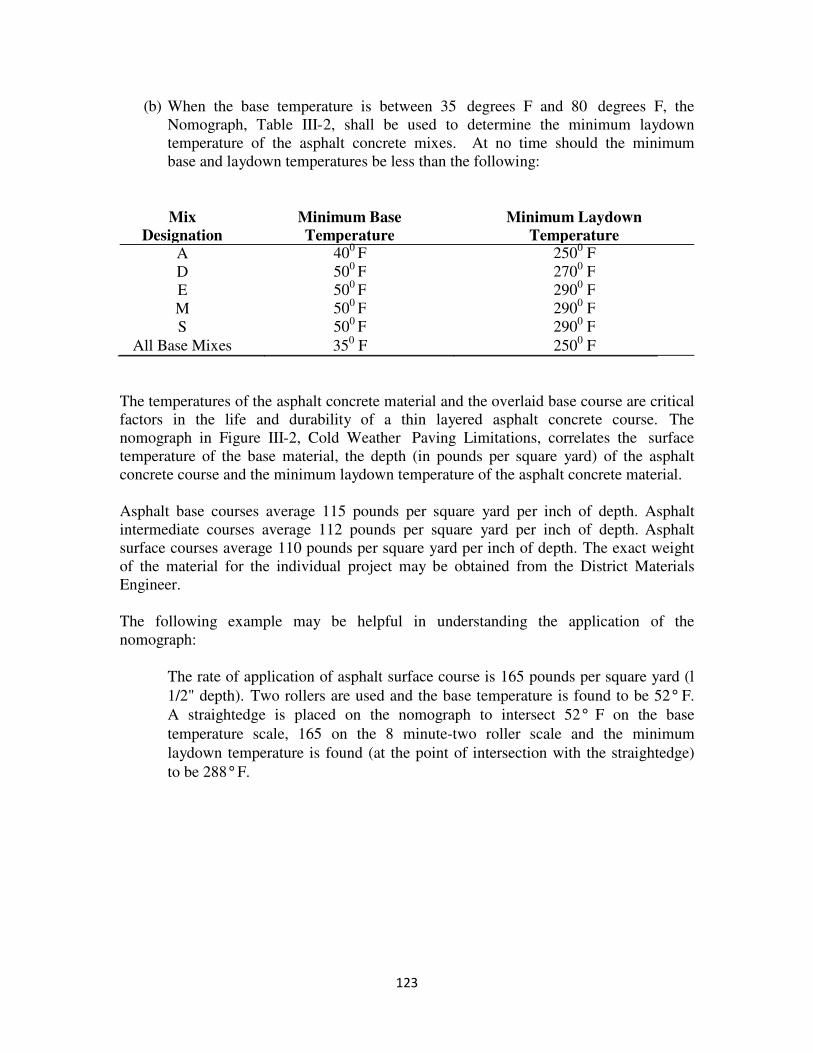
123
(b) When the base temperature is between 35 degrees F and 80 degrees F, the
Nomograph, Table III-2, shall be used to determine the minimum laydown
temperature of the asphalt concrete mixes. At no time should the minimum
base and laydown temperatures be less than the following:
Mix
Designation
Minimum Base
Temperature
Minimum Laydown
Temperature A 40
0 F 250
0 F
D 500
F 2700
F
E 500
F 2900
F
M 500
F 2900
F
S 500
F 2900
F
All Base Mixes 350
F 2500
F
The temperatures of the asphalt concrete material and the overlaid base course are critical
factors in the life and durability of a thin layered asphalt concrete course. The
nomograph in Figure III-2, Cold Weather Paving Limitations, correlates the surface
temperature of the base material, the depth (in pounds per square yard) of the asphalt
concrete course and the minimum laydown temperature of the asphalt concrete material.
Asphalt base courses average 115 pounds per square yard per inch of depth. Asphalt
intermediate courses average 112 pounds per square yard per inch of depth. Asphalt
surface courses average 110 pounds per square yard per inch of depth. The exact weight
of the material for the individual project may be obtained from the District Materials
Engineer.
The following example may be helpful in understanding the application of the
nomograph:
The rate of application of asphalt surface course is 165 pounds per square yard (l
1/2" depth). Two rollers are used and the base temperature is found to be 52° F.
A straightedge is placed on the nomograph to intersect 52° F on the base
temperature scale, 165 on the 8 minute-two roller scale and the minimum
laydown temperature is found (at the point of intersection with the straightedge)
to be 288° F.
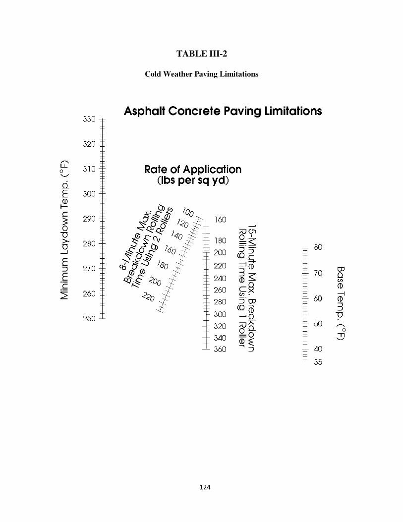
124
TABLE III-2
Cold Weather Paving Limitations
125
Note: Intermediate and base courses which are placed at rates of application which exceed
the application rates shown in Table III-2 shall conform to the requirements for the
maximum application rate shown for 8 minute and 15 minute compaction rolling as per
number of rollers used.
Equipment
The Inspector should make an inspection of the Contractor's paving equipment, checking
the condition and adjustment of the component parts. By making this inspection prior to
beginning paving operations, obvious deficiencies in the condition of the equipment may
be discovered and corrected (by the Contractor), thus avoiding delays once the work is
underway. The Inspector should realize that the finished product is the best indicator of
equipment suitability and performance.
Hauling Equipment
Trucks used for hauling asphalt concrete should be inspected for tight, clean, smooth
metal bodies. A tarpaulin, in good condition, is to be used to cover the hot material. The
tarpaulin prevents a cold crust from forming on top of the load. To be effective, the
tarpaulin should be secured at both ends of the truck body.
Prior to loading, each truck body should be sprayed with a thin coat of aliphatic
hydrocarbon invert emulsion release agent, lime solution or other approved material to
prevent the mixture from adhering thereto; however, too much oil or solution will puddle
and is detrimental to the asphalt concrete. Only a thin film is necessary. Excess oil or
solution should be drained off by tilting the bed before the truck is loaded.
Truck drivers should stop slightly short of the paver when backing up to empty their load.
This assures that the paver is in motion when it contacts the truck. If the truck bumps the
paver, the shock will be transferred to the finished surface through the screed. Any
contact between the body of the truck and the paver will be reflected in the texture of the
finished pavement. Contact between a truck and a paver should occur only at the push
rollers. Insist that the Contractor correct the cause for any contact at other points.
The Contractor should arrange his hauling operation so that each load of material arrives
on the project at fairly constant intervals. During long waits, the screed of the paver
settles into the mat and leaves depressions. Consequently, the uniform delivery of
materials is a contributing factor in the construction of a smooth riding surface.
Asphalt Concrete Paving Machines
The Inspector should familiarize himself with the mechanical features of all machinery
used on the project, so that an intelligent appraisal of the condition and adjustment of
each machine may be made. Handbooks of operating instructions are available from each
manufacturer, in which various adjustments and operating details are shown.
126
Rollers
Steel wheel rollers should be checked to determine that the wheels are capable of rolling
in a true plane. The steering and driving mechanism of all rollers must be free of
excessive play or backlash and the motor and driving transmission free from oil leaks.
Each roller should be fitted with a water tank connected to spray bars and mats on each
wheel. The wetting mats should be checked for excessive wear and the spray bars
checked for proper operation. The drive wheel should be located in the front of the roller.
Pneumatic-tire rollers must be equipped with smooth tires in good condition and of equal
size, ply, and inflation. Tire pressures and loading of the roller may be varied to give
ground contact pressures desirable. All wheels should roll true, without wobble or creep.
Miscellaneous Tools
A check should be made to see that the Contractor has available on the project an
adequate supply of asphalt rakes, lutes, shovels, brooms, straightedge and other small
tools. The Contractor is to be properly equipped with portable channelization devices,
cones or other means of protecting the freshly laid mixture from damage by traffic.
Conditioning of Existing Surface
The paving sequence should be considered and agreed upon by the Inspector and the
Contractor prior to actual construction. Once agreed upon, the sequence should not be
changed without good reason. The best surface is usually obtained when the pavement is
constructed with a minimum of interruptions.
Prior to beginning the paving operation, the Inspector should thoroughly check the
surface on which the paving material is to be placed. If the surface is:
A. Soil
The underlying material should be primed with low viscosity asphalt which should
be allowed to penetrate the soil. The grade of asphalt will be designated on the
typical section of the plans. The priming operation is described in Section 311.
When asphalt concrete to be placed has a total thickness of 4 inches or more,
priming with asphalt material will not be required on aggregate subbase or base
material.
B. Existing Hydraulic Cement Concrete Pavement
Prior to placement of asphalt concrete, longitudinal and transverse joints and cracks
in hydraulic cement concrete shall be sealed by the application of an approved joint
sealing compound.
127
C. Hydraulic Cement Concrete Base
This pavement should be prepared in accordance with Section 316 of the
Specifications. The concrete base should be allowed to cure until the concrete has
achieved the required modulus of rupture.
In the absence of beam tests, the overlay is not to be placed until 14 days after the
concrete is placed. Once the concrete base has attained the specified strength or
age, an asphalt tack should be sprayed thereon before placing the asphalt concrete
overlay. Tack coat operations are described in Section 310.
The pavement should be cleaned thoroughly before the tack material is applied to
remove all dust, dirt. Such deleterious materials reduce the adhesion of the tack.
Although not required by the Specifications, a rotary power broom appears to do
the best job and is probably the most economical tool for this purpose.
Tack material shall be uniformly applied with a pressure distributor.
D. Existing Asphalt Concrete Pavements
The method to be used in the repair of existing pavements will usually be
specified. In many cases the cause for failure in the existing pavement is due to a
failure in the base. Corrective measures will differ according to the type and
condition of the supporting materials and the severity of the distress in the
pavement.
Potholes should be filled and compacted before spreading the first course. If the
hole is filled while laying the first course, problems will be encountered while
rolling. First, the compactive effort of the roller might not reach the full depth of
the hole. Second, the roller will try to "shove" asphalt in front of the roller over
the hole.
Where deviations in the pavement are severe, a leveling course should be placed
prior to laying the surface course. The contract will usually call for a leveling
course where such is felt necessary at the time of the field inspection.
Contact surfaces of curbing, gutters, manholes, and other structures projecting into or
abutting the pavement and cold joints of asphalt shall be painted with a thick, uniform
coating of asphalt prior to placement of asphalt mixture.
128
Spreading and Finishing The Inspector should visually inspect each truck load of asphalt mixture for uniformity
and make an occasional check on the temperature of the mixture being delivered. The
requirements for the temperature of the mixture at the time of placing are stated in
placing limitations of the Specifications and this Manual.
The use of any haul truck whose frame comes in contact with the paving machine or
which bears down on the paving machine when dumping the mixture will not be
permitted. The result of either or both of these conditions will be a rough surface.
To begin paving operations, the screed should be heated to the proper temperature and
the grade controls set to construct the transverse joint. Do not change unless necessary.
As the paver proceeds, the grade or thickness control device must be adjusted to give the
spread required by the plans. As continuity of operations is essential to securing a good
pavement surface, the speed of the paver should be regulated by the plant's production.
By observing the surface texture behind the machine and checking the surface texture
with a straightedge, a malfunction in the paver or non-uniformity of mixture may be
detected. The Inspector must insist on prompt action to locate and correct any trouble
that occurs. Some of the most common difficulties encountered, together with possible
causes, are listed below:
A. Wavy Surface (Short Choppy Waves)
Worn or poorly adjusted tracks or drive chains; truck driver setting brakes too
tightly; excessive paving machine speed; push rollers not operating freely; or
some material may be falling in front of the paver.
B. Wavy Surface (Long Waves)
Excessive variation in amount of mix carried in the auger box ahead of tampers or
screed; rolling too early; roller operation too fast; over-controlling screed.
C. Excessively Open Surface Texture
Improper adjustment of tamper bar; improper speed of tamper bar; screed plate
rough or galled; excessive paving machine speed.
D. Varying Surface Texture
Insufficient mixing; overmixing; overheating of mixture; dry mixing period too
long; segregation of mix in trucks; worn or damaged screed plate.
129
E. Bleeding Patches on Surface
Asphalt concrete not uniformly mixed; excessive moisture in mix.
F. Irregular Rough Spots in Pavement
Roller standing on fresh surface; abrupt reversing of roller; truck backing into
paver; poor workmanship at transverse joints.
The pavement edge shall be marked by a string line or guide line placed far
enough ahead of the paver to maintain continuity. The line should be secured at
intervals such that it is held taut without sagging. Check the alignment of the
guide line to be certain that the correct alignment, width, and elevation of the
pavement will be assured.
The Contractor should be encouraged to maintain a constant height of material in
front of the screed. Large variations in the height of the material affect the
thickness of the finished surface. Uniform delivery of materials will minimize
this problem.
When the paving machine is equipped with an automatic grade control unit, it is
essential that the paving crew and Inspector be thoroughly familiar with its
operations and adjustments. When this unit malfunctions, it tends to compound
its errors; therefore, the paver must be stopped immediately, the pavement
corrected and the malfunction located and corrected before proceeding with
paving operations. Essentially the automatic grade control unit divorces the
screed from the upward and downward movement of the floating arms which
attach the screed to the machine, and transfers this control to the unit equipped
with a sensor element which travels on a rigidly set control guide line.
The Specifications limit the thickness of asphalt concrete which may be placed in
a single lift or layer. Limiting the depth of application improves the likelihood
that the course will have the desired strength and stability. The depth limitations
should not be exceeded, except with the approval of the Area Construction
Engineer.
If the plan thickness specified in a course exceeds the total amount that may be
placed in one layer, two or more layers may be required to place the entire course.
Good construction practices dictate that the layers in a course be of approximately
equal thickness.
The best basis for making an adjustment in the rate of material being laid is to
measure the distance traveled by a paver while spreading a truck load of material.
The actual application rate can be computed even more accurately if the
determination is based upon the spread of more than one truck. A comparison
between the actual and the plan tonnage spread in a given area is a good basis for
130
controlling all asphalt operations. Since there is a natural tendency to place more
than the specified rate, the Inspector should maintain a good check on the actual
weight per square yard placed.
1) Longitudinal Joints
When a pavement lane is constructed in more than one strip, each longitudinal
joint should be offset from each underlying joint by approximately 6 inches;
however, the longitudinal joint in the surface course is to be located at lane lines.
The screed should overlap the previously laid lane to ensure enough material to
completely fill the joint.
When matching the edge of a previously laid section of pavement, the screed of
the paver should overlap the existing edge from one to two inches and the
thickness control should be adjusted to leave the material slightly higher than the
previously laid section of pavement. Overlapping this edge will force more than
enough material into this area so that the joint is completely filled and moisture
proof. The height of the material above the previously laid edge of pavement
should be adjusted so that when the longitudinal joint is properly compacted, the
pavement will be uniform in cross-section within the tolerances specified.
2) Transverse Joints
Transverse joints should be constructed in such a manner as to provide a smooth
riding surface. The edge of existing joint should be cut back until it is
perpendicular to the edge of the pavement and vertical. The previous course
should be completely exposed to the joint.
A good construction procedure is to place blocks between the screed unit and the
existing surface when beginning operations at a transverse joint. This ensures that
the thickness of a new mat will be slightly higher than the existing surface. If the
screed is allowed to "pull off" the existing pavement, the thickness of the new
pavement will be low when compacted.
The Inspector's routine duties include the verification of weigh tickets and the
control of the location and length of spread of each load; however, the principal
duty is to ensure that the pavement is constructed to the correct grade and cross-
section set forth in the plans, and with a uniform surface texture and smooth
riding surface. To achieve these results, the Inspector must continually check the
surface on which the pavement is to be placed, the mixture in the trucks, surface
texture behind the machine, and rolling operation. The Inspector must also
evaluate the finished surface using a straightedge and string line for proper crown
and smoothness.
Paving in tandem and squaring-up at the end of each work day has been the general
practice of the Department to providing a hazard free travel way for the general public.
131
Although, consideration may be given to eliminating squaring-up at the end of each
work day if the following requirements are met:
1. Uneven roadway signing is used to advise the public.
2. The difference in elevation of adjacent lanes must not exceed 1 1/2 inches
compacted.
3. Temporary pavement marking is provided on a daily basis when needed.
Safety and convenience of the traveling public is of utmost importance; therefore, the
proximity of the ends of adjacent lanes should not be so close as to cause abrupt
maneuvers of vehicles when changing lanes. Additional consideration should be
given to type of traffic, speed, and potential problems such as ponding water.
Compaction
Rolling of the longitudinal joint should be done immediately behind the paving
operations. The rolling operation should follow the paver as closely as possible without
cracking the mat or having the mix pick up on the roller wheels. Rolling should continue
until the required density is achieved. The finish rolling should be completed while the
material is still workable enough for removal of any roller marks.
The roller wheels should be kept moist with only enough water to avoid picking up the
material. Rollers should move at a slow but uniform speed with drive roll or wheels
nearest the paver. Changes in direction should be effected gradually and rollers allowed
to roll or slowly brake to a complete stop before reversing. When rollers are parked on
the pavement they should be parked at a 45-degree angle with the centerline so that
subsequent rolling operations will remove any depressions resulting from the parked
rollers.
When the nuclear field density testing method is used to determine proper compaction,
control strips are to be constructed in accordance with the provisions of Section 304. The
District Materials personnel should be notified if assistance is needed.
Details of Inspection
Some of the more important details of inspection and corresponding corrective action for
construction of hot-mix asphalt concrete pavements are listed below:
A. Check condition and adjustment of paving machines and rollers.
B. See that traffic control is organized and functioning properly; make sure required
signs are in place.
132
C. Check application of tack coat; be certain adjoining surfaces such as gutter, curbs,
manholes, are properly tacked. All surfaces should be clean before tack is
applied. Tack coats should be applied evenly over the pavement surface.
D. Examine pavement base, see that required patching and pre-leveling is done;
make check on paving depths or spread before paving begins.
E. See that paver guide lines are set properly.
F. Check transverse joint for smoothness and appearance.
G. Watch trucks dumping into paver hopper for adverse effect on paver operation.
Each truck should empty completely and material should not accumulate in
corners.
H. Check temperature of the mixture.
I. Maintain constant inspection of mat behind paver for signs of roughness or non-
uniformity of mixture.
J. See that longitudinal joints are raked and compacted properly.
K. Make frequent checks of the spread.
L. Watch rolling operations; see that best rolling sequence is used to fit conditions;
watch for excessive speed of rollers. Check to assure that the desired pavement
contour is being achieved.
M. Inspectors should ensure that the finished grade elevations and design cross slopes
are within specified tolerances. The finished grade elevations should be checked
at the roadway centerline, each travel lane centerline, edge of pavement, and edge
of shoulder at each Station (every 30 meters for Metric projects). If checks
indicate that the surface is out of tolerance, more frequent checks should be made.
N. Keep records of truckloads used each day.
O. Make sure the project is in good order before you leave at the end of the day;
check warning lights, channelizing device. Drive through or approach the work
and attempt to view the situation through the eyes of an out-of-state motorist who
is totally unfamiliar with the route and construction work being performed.
Records for Documentation Should Include:
A. All weigh tickets must be checked by the Project Inspector. Numbering each
ticket will help maintain the trucks in the proper sequence.
133
All delivery tickets should include: (l) name of Contractor; (2) project number(s)
(3) date; (4) truck identification number; (5) load number; (6) type of material and
(7) net weight.
B. Any portion of a load not used must be returned to the plant and weighed. The
weighmaster should record the corrected weight on Form TL-102a and notify the
Project Inspector. The Inspector should record the weight of material returned on
the appropriate delivery ticket.
C. A record of the temperature checks taken on the project.
D. A copy of the approved mix design.
E. Copy of depth measurements recorded from cores, and density reports.
Inspector's Checklist
1. Do the trucks hauling asphalt have tight, clean, smooth metal bodies?
2. Are trucks equipped with operable backup alarms?
3. Are the trucks hauling asphalt equipped with the proper cover to protect the mixture?
4. Does the asphalt paver produce a finished surface as required?
5. Do the rollers leave the surface in an acceptable condition?
6. Are the weather and surface conditions during placement of the asphalt mixture as
required?
7. Are the minimum laydown temperatures as specified?
8. Are intermediate and base courses exceeding the application rate given in Table III-2
placed as specified?
9. Has the surface of existing pavement or base that is irregular been corrected as
required?
10. Have longitudinal and transverse cracks in hydraulic cement concrete been sealed
prior to placement of asphalt?
11. Have all contact surfaces and cold joints of asphalt been painted as required prior to
asphalt placement?
12. Is a tack or prime coat of asphalt applied as specified?
134
13. Are asphalt cutbacks or emulsions applied and allowed to form a tacky residue prior
to the application of the paving mixture?
14. Is tack or prime coats which have been damaged or contaminated been repaired prior
to placing the paving mixture?
15. Have irregularities in the existing surface that would result in a compacted thickness
of over 3 inches been repaired as specified?
16. Has a continuous line been placed and maintained to control pavement width and
alignment?
17. Has the longitudinal joint of each layer been offset approximately 6 inches or as
specified?
18. Is the certified Asphalt Concrete Paving Technician inspecting and straight edging
each layer as required prior to compaction?
19. Are the specified rates and depth adhered to when placing asphalt concrete base,
intermediate and surface course?
20. Does rolling begin immediately after placement and continue until the mixture is
thoroughly and uniformly compacted?
21. Are there sufficient rollers to obtain the required compaction of the mixture?
22. Has the rolling of the mixture been accomplished as required by the Specifications?
23. In areas not accessible to rollers, has the material been compacted as required?
24. Are the edges of the pavement surface true curves or tangents as required?
25. Are the surfaces of the compacted courses protected until the material has cooled
sufficiently to support traffic without marring?
26. Does the density of the compacted course meet the requirements as specified?
27. Did the Contractor furnish and operate a nuclear density gage, which had been
calibrated within the previous 12 months by an approved calibration service, in
accordance with the requirements of this section?
28. Has a control strip been constructed for each roadway, shoulder course, and each lift
of each course as required?
135
29. Have the required number of density tests been taken by the Contractor on specified
courses?
30. Have the rollers continued until roller marks are eliminated and the required density
has been obtained?
31. Has a transverse joint been cut on the previous run as specified?
32. Has a brush coat of asphalt been applied to transverse joints as directed?
33. Have joints adjacent to curbs, gutters, or adjoining pavement been set up to a height
sufficient to receive full compression under the rollers?
34. Has the Contractor cut the testing samples and replaced the material as required?
35. Has the Contractor taken corrective actions to fix surface areas out of tolerance prior
to determining the pavement thickness?
36. Does the thickness of the base course meet the requirements?
136
SECTION 316 - HYDRAULIC CEMENT CONCRETE
PAVEMENT
Description
The construction of concrete pavement is a highly mechanized operation which requires
inspection of a vast quantity of material and a working knowledge of numerous types of
equipment. Inspectors assigned to this work should be thoroughly familiar with the
Specifications, Special Provisions, construction details, and sequence of operations. Prior
to the start of paving work, a meeting should be held between the Contractor's
supervisory personnel and the Project Inspector to discuss the sequence of operations.
Materials
The Inspector must be familiar with the source and type of aggregate intended for use,
mix proportions, moisture content determination, method of determining scale weights,
batching equipment, tests and reports. A review of the Manual of Instructions - Materials
Division and the Study Guide for the Hydraulic Cement Concrete Certifications School
will be helpful.
All sources supplying concrete to the Department shall be required to have present during
the batching operations, a Certified Concrete Batcher or a Certified Concrete Technician.
A Certified Concrete Batcher is that person who actually performs the batching
operation. He shall never initiate adjustments and will be permitted to implement
adjustments only at the direction of the Certified Concrete Technician, unless his
certification carries this special authorization. A Certified Concrete Technician is that
person who is capable of performing adjustments in the proportioning of materials used
to produce the specified concrete, should such adjustments prove necessary. Certification
shall be by the Department, awarded upon satisfactory completion of an examination.
The concrete producer shall so plan his batching operations so that delays do not occur
due to the absence of certified personnel. In cases of emergency, the concrete producer
shall have readily available for service a Certified Concrete Batcher or a Certified
Concrete Technician to replace the regular personnel assigned to these jobs. Should
cases of extreme emergency arise during actual batching operations, this requirement will
be temporarily waived by the Engineer in order to complete the placing of concrete on
the portion or section of a structure involved. Additional batching operations shall not be
initiated until the services of a Certified Concrete Batcher and Certified Concrete
Technician have been obtained.
The Project Inspector will never assume by act or word the responsibility of batch control
adjustments, calculations, or the setting of dials, gages, scales, and meters.
137
Equipment Equipment plays an important role in concrete paving. The Inspector should familiarize
himself with the mechanical features of all machinery used on the project so that an
intelligent appraisal of the condition and adjustment of each machine can be made.
Handbooks of operation instructions are available from equipment manufacturers which
explain various adjustments and operating procedures.
In the event the manufacturer's instructions for an individual piece of equipment differ
from the procedure outlined herein, comply with the manufacturer's instructions. All
paving machinery should be correctly adjusted within the first 100 feet of operation.
Examine each machine's performance carefully and require adjustments as soon as the
need for such is indicated. Continued use of an unsatisfactory piece of equipment can
only result in an excessive amount of corrective work.
Equipment that rides on forms should have a scraper that will keep the top of the forms
and the wheels clean of concrete.
Placing Reinforcing Steel for Continuously Reinforced Pavement: At each location
where five or more consecutive days will elapse between placement operations, a "leave
out" joint shall be installed as detailed on the plans. Longitudinal bars shall be positioned in
the finished pavement within ±1/2 inch of the specified vertical position and ±1 inch of the
specified horizontal position with a cover of at least 2 inches.
Pre-bent deformed tie bars, Grade 40 or 60, may be used in the joint between the mainline
and ramp pavement to facilitate the use of the slipform paver. Bars shall be pre-bent with
equipment designed especially for fabricating 90-degree bends in 5/8-inch deformed bars
without damage to the bars. Side forms of the slipform paver shall be designed in a manner
so that the pre-bent tie bars can be inserted in an appropriate slot and will pass between the
edge of the pavement and the inside face of the trailing forms as the paver advances.
When reinforced concrete pavement is placed in two layers, the entire width of the bottom
layer shall be vibrated and struck off to such length and depth that the sheet of fabric or bar
mat may be laid full length on the concrete in its final position without further manipulation.
The reinforcement shall then be placed directly on the concrete, after which the top layer of
concrete shall be placed, struck off, and screeded. Any portion of the bottom layer of
concrete that has been placed more than 30 minutes without being covered with the top layer
shall be removed and replaced with freshly mixed concrete at the Contractor’s expense.
When reinforced concrete is placed in one layer, the reinforcement may be positioned in
advance of concrete placement or placed by approved mechanical or vibratory means in
fresh concrete after spreading.
Reinforcing steel shall be straight, and its surface condition shall conform to the
requirements of Section 406.
138
Setting Forms Forms should be checked to ensure that they are straight, clean, and oiled; the face is
perpendicular to the base, flanges are not bent; and locking devices are in proper working
order.
The subgrade on which forms are to rest is to be cut true to grade, usually from a
reference string line. When forms are set, they are to be firmly supported for their full
lengths.
Pins must be adequate in length to avoid perceptible movement by equipment and locked.
Locking devices must be properly fastened. Width between the edges of pavement must
be set correctly. After forms are set, it is advisable to sight along the top of the forms to
detect obvious deviations in grade or alignment.
Conditioning of Subgrade or Subbase Course After forms are set or track path cut for slip form paving, the fine grade should be
checked. If the base is low, material should be added and recompacted in accordance
with the Specifications. The Inspector should check the grade by measuring down to the
subgrade from a taut string or wire across the forms at random intervals. Loose material
often accumulates at the inside edge of the forms. Any loose material found here should
be removed. The slab thickness is most often checked at the edges, so the depth should
be double checked here. The thickness of a concrete slab affects the final payment for
such work and most Contractors appreciate a close check.
The moisture condition of the subbase should also be checked. If the subbase is too dry,
water needed for hydration of cement will be "pulled out" of the concrete. The subgrade
should be uniformly moist, but not muddy, at the time the concrete is placed.
Final tests and depth checks for the subgrade or base course should be completed by the
Materials Section prior to the start of the paving operation as outlined in the Manual of
Instructions - Materials Division.
Placing Concrete - Regardless of whether concrete is mixed in site mixers, stationary
mixers, or truck mixers, it is the responsibility of the job site Inspector to determine that it
is properly mixed and meets Specification requirements for slump, air content,
uniformity, and desired workability at the time of discharge into the spreader or forms.
The Inspector at a paving mixer must see that dry batches are delivered in the proper
manner and condition and are dumped in the skip without loss of materials and should
check to see that the skip empties all material into the mixer without waste. The mixer is
to be regulated so that some water flows into the drum in advance of cement and
aggregate and shall continue to flow for a specified period after all the cement and
aggregates are in the drum. Proper blending of ingredients is important for proper
mixing.
139
The Specifications regulate the amount of time that can elapse between the introduction
of cement to the mix and discharge of the mix. These maximum time limits apply to
concrete delivered in both agitating and non-agitating type trucks.
Concrete must be placed on the subgrade in such a manner as to prevent segregation and
to require a minimum of redistribution (additional movement). Paving mixer buckets are
best discharged while still in motion moving away from the paver. Concrete dumped in
piles causes non-uniformity of consolidation and additional strain on the forms and
spreader. This, in turn, will probably cause increased finishing work to obtain a good
riding surface. When it is necessary to spread concrete by hand, it should be done with a
shovel instead of a rake or similar tool. Vibrators should never be used to move concrete.
Extreme caution must be employed when placing concrete around joint assemblies,
dowels, expansion joints to avoid displacement of these items.
Normally, the mixing and placing of concrete pavement should be discontinued when the
ambient air temperature is below 400
F. When concrete is mixed and placed at
temperatures lower than those noted above, it should be produced, delivered and finished
in a manner to provide for a minimum loss of heat. Finished concrete must be cured and
protected in a manner that will protect it during the period in which it is susceptible to
frost and freeze damage.
In cold weather, the Contractor is required to cover pavement with insulating material to
prevent the slab from freezing. The surface temperature of the concrete is required to be
kept above 40°F for the first 72 hours. The blanketing material must be kept in place an
additional 48 hours in the event freezing air temperatures are expected to continue.
Hot, dry or windy conditions cause rapid surface drying, rapid temperature changes and
undesirable high temperatures in the concrete during the early stages of hardening. Such
condition(s) often cause the loss of moisture from the pavement surface faster than it can
be replaced by normal bleeding thereby causing plastic shrinkage cracks to form. It may
be necessary under extreme conditions to cool the mixing water and aggregate stockpiles
in order to lower the temperature of the concrete. In any event, the curing medium must
be applied at the earliest possible time.
Prior to the start of paving operations, the Inspector should check to see that the
Contractor has sufficient material on hand, such as burlap, polyethylene sheeting or other
approved material, to properly protect the pavement surface in case of rain. Sudden
showers which might occur during paving operations or immediately after finishing
operations, require the exposed surface of the fresh concrete to be covered to prevent
washing the cement particles out of the surface. Mixing and placing of concrete should
cease immediately in the event of rain.
If rain continues only for a short period, the protective covering may be removed and
finishing completed. In case the rain continues, finishing may be accomplished by
140
rolling back a few feet of protective cover at a time and replacing it immediately after
finishing.
Concrete Pavement - Slip Form Method
The Contractor may elect to use the slip form method of paving in lieu of the
conventional form type method. Prior to beginning slip form operations, the base
material must be uniformly compacted and free from irregularities.
Special attention must be given to the track path of the slip form paving equipment.
Some slip form pavers use the track path as the profile grade. The track path is normally
located on the edge of the base material. In this case, the supporting material must be
compacted and graded to match the plan profile grade.
The tracks of the slip form paving equipment must not be allowed to run over concrete
spills or other material. Such obstructions, if left unattended, will bring about
irregularities in the concrete finish. Spills and other material in the track path are to be
removed.
The Contractor may elect to use a control guide wire (string line) for both roadway
alignment and profile grade. The Inspector should spot check the control guide wire
from the fine grade hubs. The control guide wire should be taut, free from obstructions
and without measurable sag between supports. A final check of the control guide wire is
to be made prior to paving by sighting along the wire for irregularities.
The concrete should be of such consistency that it can be spread, consolidated, and
finished in a single pass without appreciable slumping of the outer edges. Edge slump
can be compensated for by slightly tapering the trailing forms in a front-to-back
convergence such that the concrete will be extruded upward. However, the consistency
of the concrete is an extremely important control in slip form paving. An ideal concrete
slump is 1 1/2 to 2 inches.
The method of installing headers is to be reviewed with the Contractor's representative
prior to the paving operation. Special techniques are necessary for the placement of
additional reinforcement and maintaining the proper profile grade. The Contractor
should plan the concrete delivery in such a manner that the header can be placed opposite
a finish grade hub.
Caution should be taken to avoid paving when rain is imminent. A sudden shower can
produce serious consequences in the quality of the paving texture.
Test Specimens
The Manual of Instructions - Materials Division outlines the procedures that apply to
concrete test beams.
141
Strike-Off of Concrete and Placement of Reinforcement The concrete spreader should be adjusted so that concrete is struck off uniformly across
the entire width of spread.
When wire mesh is used, the mesh may be placed by means of two layer construction of
the concrete or by the use of an approved placing machine which vibrates the
reinforcement into proper position after full thickness of concrete is placed. When mesh
is placed by means of two layer construction no more than 30 minutes is to elapse before
placing the top layer of concrete. If an approved placing machine is used, it must be
checked for proper adjustment to assure that all reinforcement is positioned at the proper
depth and that it does not move out of position during the remaining finishing operations.
A continual check should be maintained for the location of reinforcement regardless of
the method of installation.
When wire mesh, bar mat, or continuous reinforcement is required, it should be stored off
the ground in a manner that will avoid damage and be kept clean. Wire mesh and
reinforcing steel are to be free from dirt, oil, paint, grease and excessive rust at the time
the concrete is placed.
Joints Dowel Supporting Assemblies
When dowel supporting assemblies are required for transverse joints, they must be laid
out and marked in such a manner that the exact centerline of the assembly can be
reestablished. Generally, they are held in correct position by the use of metal stakes or
pins that are left in the base material. It is very important that all dowels in a dowel
assembly be parallel to each other and form a straight line. If not, a "locked joint" will
result; a condition in which the normal expansion and contraction movement designed to
occur at the joint is prevented from occurring.
Prior to placement, dowel assemblies should be visually inspected. Occasionally, metal
burrs will be found that will create a locked joint if placed in the concrete. These burrs
are the result of the shearing operation at the manufacturer's plant. The assembly can be
used once these burrs are removed by filing, grinding or otherwise corrected.
The free end of all dowel assemblies should be painted with an approved coating material
or tar paint. In addition, before placing, the free end of the bars should be coated with
asphalt or other approved lubricant. Dowel caps are required for the free end of all
expansion joints. The spacing of all joints should be in accordance with the requirements
of the plans, Standards, and Specifications.
142
Tiebars
Tiebars installed across the centerline should be parallel to the surface and installed as
shown in the Standards. Unless an approved mechanical device, operating immediately
behind the spreader or behind the strike off of a slip form paver, is used for the
installation, the tiebars must be installed ahead of placing the concrete and held securely
in position.
Tie Bolts
Tie bolts used for multiple lane paving must be placed in proper position on the face of
the roadway forms, as shown in the Standards.
Sawing
The time for sawing will vary with weather and atmospheric conditions as well as the
hardness of the coarse aggregate. Slight raveling is not objectionable and generally is an
indication that sawing is being done at the proper time. Joints must be sawed over the
exact center of load transfer devices and perpendicular to the surface. If sawing is not
performed at the proper time, random or uncontrolled cracks will occur.
Final Strike-Off, Consolidation and Finishing
Immediately after spreading, the concrete should be screeded and consolidated by means
of approved mechanical finishing and vibrating equipment.
The purpose of the finishing machine is to not only provide some additional
consolidation of the concrete, but also to produce a reasonably smooth, plane surface at
the elevation and cross section specified.
When the spreader and finishing machine are in proper adjustment, there will be a
uniform roll of concrete in front of each screed. The roll in front of the first screed
should be larger than the roll in front of the back screed. The roll of concrete in front of
the back screed should be sufficient (about as large as a man's wrist) to provide a uniform
surface. If an excess of concrete is being carried forward in front of the screeds, it will
tend to float or lift the machine off the forms. In addition, there will be "surging" behind
the screed to complicate the proper function of the trailing equipment. As the work
progresses, the tilt and speed of the screeds may need to be adjusted to adapt to the
particular mix being used, to eliminate tearing, and to control the amount of surge. With
stiff, harsh mixes, the screed's oscillating speed should normally be rapid with a long
stroke and slow forward speed. With more fluid mixes, the screed action should be
decreased, both in speed and length of stroke with the forward speed increased. The
number of screedings will be determined by field conditions. Excess screedings should
be avoided since it tends to result in undesirable quantities of low-strength mortar on the
surface. The finishing machine wheels and the top of the forms should be kept clean at
all times.
143
Vibrators, which may be attached to the back of the spreader, the front of the finishing
machine, or on a separate carrier, must conform to the Specifications and be mounted in
such a manner that they will not come in contact with reinforcement, subgrade, or forms.
The entire width of the pavement must be thoroughly vibrated in a manner that will be
effective for the full depth. All vibration should be controlled by the forward movement
of the spreader so that vibration automatically ceases when the forward movement of the
spreader is stopped.
After consolidating and screeding, the concrete is to be floated to remove irregularities
left by previous operations and by shrinkage. This operation may be done by the use of
longitudinal or a transverse float. The time of floating will depend on field conditions.
Floating should be held to a minimum during the period when the worst bleeding is
occurring in order to avoid the over dispersion of cement particles in the surface paste.
The longitudinal float should be operated so that the entire surface area is covered at least
twice. This is accomplished by overlapping the previous transverse pass by one half the
length of the float. Excessive floating should be avoided. If excessive cutting or filling is
required, the equipment should be checked and necessary adjustments made to eliminate
the condition. When operating properly, the longitudinal float should carry a small roll of
concrete along all but approximately the rear 2 feet of its length.
When the transverse float is used, the time of operation must be adjusted to field
conditions. This will be similar to the requirements for using a longitudinal float. The
screed or screeds working ahead of the transverse float should carry a uniform roll of
concrete so that the transverse float will leave a smooth uniform surface free of screed
marks with a minimum of surging.
Regardless of the type of float used, a continuous operation at a uniform rate of speed is
necessary for obtaining the most desirable finished product.
Normally, the addition of water to the surface to facilitate finishing is not permitted;
however, the practice of wetting the surfaces of the finishing equipment with a fine mist
spray is acceptable provided large droplets of water are not conveyed directly to the
concrete surface.
Station Numbers and Dates
Stenciling Station Numbers and Dates - Before concrete takes its final set and after
finishing operations are completed, the Contractor shall stencil station numbers and dates
into the pavement in accordance with the standard drawings. The dies for numbering and
dating will be furnished by and remain the property of the Department. Dies or numerals
lost or damaged by the Contractor shall be replaced at his expense.
144
Curing
The "curing of concrete" is the operation which is performed to assist the cement
hydration process to take place in such a manner that the concrete will be strong, durable
and reasonably impervious. The natural tendency is for the water present on or near the
surface to evaporate and thus cause a cessation of the hydration process. When
conditions of low humidity, high wind, high temperatures, or combinations of the
aforementioned occur, the rate of evaporation can take place almost as rapidly as if a
giant blotter were to be placed on the surface.
When the rate of evaporation at the surface exceeds the rate at which water escapes
(bleeds) to the surface, plastic shrinkage cracking is likely to occur. If such cracks extend
down through the full depth of pavement, the structural capacity of the pavement is lost.
Rain water and deicing chemicals will gain entry through the cracks and cause rapid
deterioration of the pavement through freeze and thaw action.
The ability of an approved curing material to prevent the escape of moisture from the
concrete is related primarily to the promptness and completeness of the application.
Curing material must be applied as soon as practicable after the surface has been
textured.
Liquid Membrane
Curing compound is to be applied uniformly at the specified rate. Frequent checks
should be made of the quantity used in relation to surface area to insure proper rate of
application. Since white pigment particles will settle out of solution, all curing
compound must be mixed thoroughly before and while it is used. Should the curing
agent be damaged by rain or other causes, the pavement should be immediately covered
by an additional application of curing compound.
Surface Test
An soon as possible after concrete has set, the surface should be checked with a
straightedge or other specified device. All irregularities varying by more than the
Specification requirements should be corrected with an approved cutting tool. The
Inspector should consult with the Area Construction Engineer before ordering surface
corrections.
Removing Forms
Side forms should not be removed from freshly placed concrete until the concrete has set
for the specified time. The concrete should be hardened to the extent that spalling or
145
other damage will not occur. Immediately upon removal of forms, any honeycomb must
be patched and the edges of pavement cured in an approved manner.
Sealing Joints
Joints, whether sawed or formed, must be cleaned and surface dry at the time of sealing.
The sealing of joints with approved material should be completed prior to opening the
pavement to any traffic including the Contractor's equipment.
Protection of Pavement
The edges and the surface of the pavement should be protected against damage by the
public, and the Contractor's forces and equipment. The Contractor should be warned of
the advisability of posting watchmen along sections of newly placed concrete in order to
discourage acts of malicious vandalism until the concrete has attained sufficient set.
Checking Finished Grade and Cross Slope
Inspectors should ensure that the finished grade elevations and design cross slopes are
within specified tolerances. The finished grade elevations should be checked at the
roadway centerline, each travel lane centerline, edge of pavement, and edge of shoulder
at each Station (every 30 meters for Metric projects). If checks indicate that the surface
is out of tolerance, more frequent checks should be made.
Tolerance in Pavement Thickness
Prior to final acceptance, the Materials Division will core the pavement to determine the
actual thickness. The thickness will be determined by the average caliper measurement
specified in Section 316 of the Specifications.
If pavement thickness is not within the allowable tolerance, deductions for deficient
pavement will be made in accordance with the specified method of adjusting unit price.
However, the adjusted unit price for deficiencies need not appear on the monthly progress
estimate unless specified instructions to do so are issued by the District Office.
Basis of Payment
Normally, pavement is measured in square yards. The width for calculations may be
taken from the typical cross sections. The length should be measured horizontally along
the centerline of pavement.
All paving records and reports should be kept current and complete. The project records
must include sufficient test reports or certifications to cover the material used:
1. Wire mesh.
146
2. Steel reinforcing bars.
3. Tie bars.
4. Dowel assemblies.
5. Expansion joint material.
6. Joint sealing material.
7. Curing compounds or materials.
8. Other materials for which test are required.
The following information should be included in the "Inspector's Daily Report."
1. The amount of concrete received and used. If a batch or load of concrete is
wasted or rejected, then a reason should be noted on the appropriate ticket and in
the "Inspector's Daily Report."
2. Stations between which pavement was placed and the number of square yards
placed.
3. Record of Test Beams made or broken as outlined in the Manual of Instructions -
Materials Division.
4. Contractor's labor and equipment.
5. Concrete pavement curing temperature ranges
6. The location of any joints which are not placed according to plans.
A field paving book is to be maintained for the daily paving train tests and measurements.
The following tests and checks are to be located by time and station and initialed by the
Inspector:
1. Air content test.
2. Consistency test.
3. Concrete and air temperatures.
4. Reinforcement cover checks.
5. Pavement depth checks.
147
When not in use in the field, the field paving book should be stored with the project
records.
Inspector's Checklist
1. Does the Contractor have a Certified Concrete Field Technician present during
placement of pavement?
2. Is the concrete sufficiently cohesive to prevent detrimental sloughing of the edges
when the slip form method is used?
3. Does the Contractor have sufficient equipment and tools to place and finish the
concrete pavement as required?
4. Does the Contractor have sufficient equipment on hand to protect the concrete from
freezing?
5. Do the forms and bulkheads meet the requirements of this section?
6. Do the vibrators being used meet the requirements of this section?
7. Does the surface of the concrete base course meet the requirements when tested under
a 10 foot straightedge and also have a heavy broomed texture?
8. Are "leave out" joints installed when required and as detailed on the plans?
9. Are the side forms of the slip form paver designed so that tie bars can be placed as
specified?
10. Have the forms been pinned sufficiently and locked in place to hold line and grade as
required?
11. Prior to concrete placement, are the forms cleaned and oiled?
12. Is the alignment and grade of the forms checked and corrected as required by the
Contractor?
13. Is the concrete placed and finished in accordance with this section?
14. Has the concrete in an adjoining lane attained the strength requirements before
mechanical equipment is operated on it?
15. If random or uncontrolled cracking occurs, have concrete joints or slabs been repaired
as specified?
148
16. Are the deformed tie bars and longitudinal joints installed as specified?
17. Are approved devices used to form the joints and the groove sealed with joint
material as required?
18. Are saw cut joints in accordance with the requirements of this section?
19. Are transverse expansion joints properly formed and sealed with filler placed at the
proper grade and elevation?
20. Are transverse contraction joints installed as specified?
21. Are the plain dowels held in place as required?
22. Is the free end of each dowel treated as specified?
23. Are isolation joints formed for structures in the pavement as required?
24. Is concrete mechanically vibrated to prevent voids and segregation?
25. Does the riding surface have a gritty texture and is it grooved as required?
26. Is the surface and sides of the pavement sprayed uniformly with curing compound
which is continuously and effectively agitated during application?
27. Is the PE film being used for curing the type specified for the time of the year?
28. Has the Contractor maintained the surface temperature of the concrete as specified?
29. Is the curing material placed as early as possible in hot, low humidity or windy
weather?
30. Is the paved riding surface in compliance with the requirements of this section?
31. Are the forms left in place for the required time before removal?
32. Are major honeycombed areas removed and replaced?
33. Are all joints thoroughly cleaned and sealed prior to opening the pavement to traffic?
34. Is the joint for hot-poured, or silicone sealer sealed only if the air temperature is at
least 40 degrees F.?
35. Is the hot-poured sealer material stirred during heating and prevented from bonding to
the filler as specified?

149
36. Is the sealer applied and tooled to form a recess as specified?
37. Is the contractor protecting the pavement from the effects of rain and all traffic as
specified?
38. Does the pavement meet the thickness tolerance?

150
BRIDGES AND STRUCTURES
151
SECTION 401 - STRUCTURE EXCAVATION
Description
Foundations are a very important part of bridge construction. If the underlying soil will
not support the design loads, damaging settlements or overturning may result. For this
reason, the Inspector should pay particular attention to the type and condition of material
encountered during excavation. The materials encountered should be compared with the
substrata shown on the plans. Significant variations should be reported to the Area
Construction Engineer.
During excavation, nearby buildings, utilities, sloping ground surfaces, or other
substructure elements may be damaged. While inspecting such operations, be mindful of
the possibility that it may become necessary to modify adjacent slopes or to support the
sides of the excavation, thereby preventing damage to adjoining property; however, this
is the Contractor's responsibility. Bring the possibility of property damage to the
Contractor's attention, leave the necessary corrective measures to his initiative and
document such notification in the Inspector's Daily Report.
Preparation of Foundations For Footings
Stability is the key to a good foundation. Generally, dense sands or gravels have the
desired stability. Clays may be acceptable. However, muck and soft clays should be
removed.
Rock, if sound, will provide a satisfactory foundation. Sedimentary types of rock may
have voids and should be investigated by probing, sounding or drilling before any
concrete is placed. Rock surfaces upon which concrete is to be placed should be
relatively level. When sloping rock is encountered at or near footing elevation, the rock
should be stepped or serrated.
Not only rock, but all foundation materials must be thoroughly examined. If there occurs
a large difference in the types of soil or combination of soil and rock within a footing,
advise the Area Construction Engineer. Abnormal conditions encountered during
excavation are to be noted in detail in the diary along with a description of the physical
characteristics of the material upon which the footing is placed. Normally, the Area
Construction Engineer is to examine and approve all foundations prior to the placing of
concrete in footings. The name of the person approving the foundation and the date of
approval should be noted in the diary.
Ground water is often encountered above the desired foundation elevation. This water
must be prevented from saturating the foundation soils. One way of preventing saturation
is by constructing sumps in the excavation. These serve as receptacles for excess water
and expedite pumping operations. All sumps should be located outside the footing forms.
In addition, other precautions may have to be taken to ensure that water flow will not
152
wash cement from freshly placed concrete. Water from foundations is not to be pumped
directly back into the stream.
Before the Contractor can begin work on, over, or under Railway property, approval must
be obtained. The Contractor must submit to the Department his plan of operations for
shoring, sheeting, or cofferdaming for construction of pier foundations and other
excavation adjacent to the railway tracks. The Contractor may be required to show
information in sufficient detail so that his design can be easily checked or may be
required to submit his design calculations. This information should be submitted to the
District Administrator for review and subsequently submit the Contractor's plan directly
to the Railway for their approval.
Cofferdams and Shoring
A cofferdam is a structure, generally of a temporary nature, constructed for the purpose
of keeping water and earth out of the excavation area. Normally a cofferdam is placed
before excavation begins. A simple type of cofferdam is a box-like enclosure of sheet
piling within which the excavation is made, pumped dry, and the foundation constructed.
When an underwater foundation must be constructed in the dry, a layer of concrete may
be used to seal the bottom of the cofferdam. In this situation, a layer of concrete is
deposited within the cofferdam by means of a tremie. After the concrete has cured, the
water inside the cofferdam is pumped out. The weight of the concrete seal resists the
pressure created by the water on the outside of the cofferdam and prevents water from
entering. Once the cofferdam is pumped out, the area can be cleaned and the footing
constructed.
Cofferdams must be of sufficient size to accommodate the necessary form work, drainage
details such as sumps, clearance for batter piles, and clearance for minor deviations that
occur in the installation of the walls.
Shoring refers to temporary support of the sides of an excavation and must conform to
the Federal OSHA Standards and Virginia OSHA Standards. It is a wall type structure
constructed of wood or steel and is installed as the excavation proceeds. Although the
Contractor is responsible for the adequacy of shoring used, any seemingly unsafe
condition should be brought to the attention of the Contractor and the Area Construction
Engineer.
Backfill Material
The key to a stable backfill is the use of good materials and proper placement techniques.
Intermittent inspection is essential to the obtainment of a properly constructed backfill.
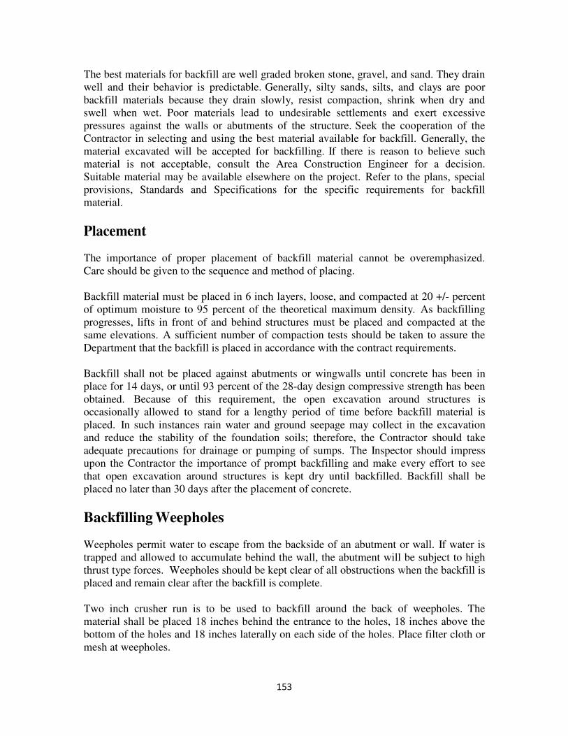
153
The best materials for backfill are well graded broken stone, gravel, and sand. They drain
well and their behavior is predictable. Generally, silty sands, silts, and clays are poor
backfill materials because they drain slowly, resist compaction, shrink when dry and
swell when wet. Poor materials lead to undesirable settlements and exert excessive
pressures against the walls or abutments of the structure. Seek the cooperation of the
Contractor in selecting and using the best material available for backfill. Generally, the
material excavated will be accepted for backfilling. If there is reason to believe such
material is not acceptable, consult the Area Construction Engineer for a decision.
Suitable material may be available elsewhere on the project. Refer to the plans, special
provisions, Standards and Specifications for the specific requirements for backfill
material.
Placement
The importance of proper placement of backfill material cannot be overemphasized.
Care should be given to the sequence and method of placing.
Backfill material must be placed in 6 inch layers, loose, and compacted at 20 +/- percent
of optimum moisture to 95 percent of the theoretical maximum density. As backfilling
progresses, lifts in front of and behind structures must be placed and compacted at the
same elevations. A sufficient number of compaction tests should be taken to assure the
Department that the backfill is placed in accordance with the contract requirements.
Backfill shall not be placed against abutments or wingwalls until concrete has been in
place for 14 days, or until 93 percent of the 28-day design compressive strength has been
obtained. Because of this requirement, the open excavation around structures is
occasionally allowed to stand for a lengthy period of time before backfill material is
placed. In such instances rain water and ground seepage may collect in the excavation
and reduce the stability of the foundation soils; therefore, the Contractor should take
adequate precautions for drainage or pumping of sumps. The Inspector should impress
upon the Contractor the importance of prompt backfilling and make every effort to see
that open excavation around structures is kept dry until backfilled. Backfill shall be
placed no later than 30 days after the placement of concrete.
Backfilling Weepholes
Weepholes permit water to escape from the backside of an abutment or wall. If water is
trapped and allowed to accumulate behind the wall, the abutment will be subject to high
thrust type forces. Weepholes should be kept clear of all obstructions when the backfill is
placed and remain clear after the backfill is complete.
Two inch crusher run is to be used to backfill around the back of weepholes. The
material shall be placed 18 inches behind the entrance to the holes, 18 inches above the
bottom of the holes and 18 inches laterally on each side of the holes. Place filter cloth or
mesh at weepholes.
154
Records
The project records are to include the following field information and calculations:
1. Original ground level notes including sketch indicating location of irregularities.
2. The actual elevation of the footing bottom.
3. The actual horizontal dimensions of the excavated area. (Pay quantity is to
include the actual material excavated limited to 18 inches outside of footing
neatlines.)
4. When the footing is to be keyed into rock, record the actual dimensions of the
excavated area.
5. The vertical limits of excavation are from the bottom cross sections of the footing
to the original ground cross sections. When structure excavation is in a fill area,
excavation above the original ground will not be included for payment. When
footing is on piles, fill to top of footing and excavate to bottom. Pay to top of
footing in this case.
6. Structure excavation calculations.
7. Date, name and title of person who approved the foundation.
Inspector's Checklist
1. Is an area staked off 18 inches around the neatlines of the footing and record original
ground elevations, including irregularities, prior to excavation operations?
2. Does the Inspector verify the Contractor's layout of excavation area?
3. Does the Contractor install the required erosion and siltation control devices?
4. Does the Contractor verify the need for cofferdams or shoring to retain the
embankment in compliance with applicable safety codes during excavation?
5. Does the Inspector check the plans for the bottom elevation of the footing and notify
the Contractor not to exceed this elevation?
6. Does the Contractor examine the foundation for proper location, dimensions, grade
and stability? The Contractor is to explore at least five feet below the contemplated
foundation elevation. Usually, three to five drilled holes or rod soundings are
sufficient to determine the adequacy of the sub-foundation. Note location of
exploration in project records.
155
7. Does the Inspector notify the Area Construction Engineer and/or District Bridge
Engineer for inspection and approval of foundation?
8. Does the Inspector record foundation irregularities and computed excavation
quantities?
9. Is the foundation cleaned of loose materials prior to placement of concrete?
10. Are the concrete strength requirements met prior to form removal and subsequent
backfill?
11. Is the backfill placed in uniform lifts and compacted properly?
12. Has the material used for backfill been approved by the Engineer?
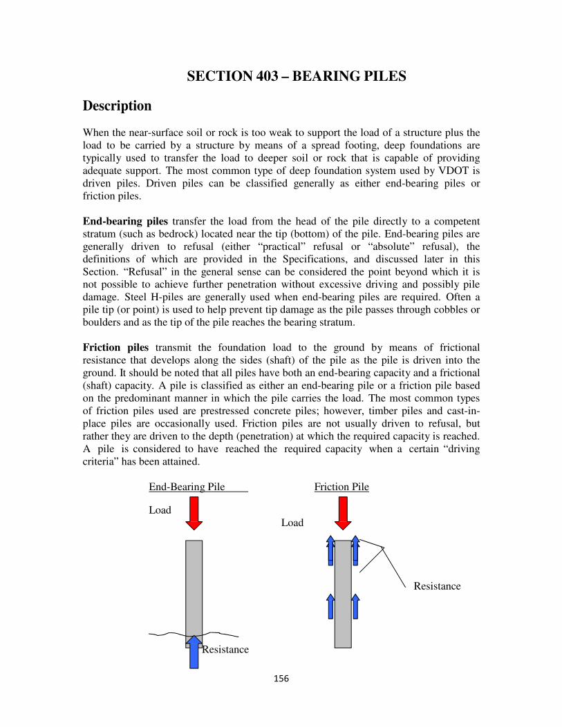
156
SECTION 403 – BEARING PILES
Description
When the near-surface soil or rock is too weak to support the load of a structure plus the
load to be carried by a structure by means of a spread footing, deep foundations are
typically used to transfer the load to deeper soil or rock that is capable of providing
adequate support. The most common type of deep foundation system used by VDOT is
driven piles. Driven piles can be classified generally as either end-bearing piles or
friction piles.
End-bearing piles transfer the load from the head of the pile directly to a competent
stratum (such as bedrock) located near the tip (bottom) of the pile. End-bearing piles are
generally driven to refusal (either “practical” refusal or “absolute” refusal), the
definitions of which are provided in the Specifications, and discussed later in this
Section. “Refusal” in the general sense can be considered the point beyond which it is
not possible to achieve further penetration without excessive driving and possibly pile
damage. Steel H-piles are generally used when end-bearing piles are required. Often a
pile tip (or point) is used to help prevent tip damage as the pile passes through cobbles or
boulders and as the tip of the pile reaches the bearing stratum.
Friction piles transmit the foundation load to the ground by means of frictional
resistance that develops along the sides (shaft) of the pile as the pile is driven into the
ground. It should be noted that all piles have both an end-bearing capacity and a frictional
(shaft) capacity. A pile is classified as either an end-bearing pile or a friction pile based
on the predominant manner in which the pile carries the load. The most common types
of friction piles used are prestressed concrete piles; however, timber piles and cast-in-
place piles are occasionally used. Friction piles are not usually driven to refusal, but
rather they are driven to the depth (penetration) at which the required capacity is reached.
A pile is considered to have reached the required capacity when a certain “driving
criteria” has been attained.
End-Bearing Pile Friction Pile
Load
Load
Resistance
Resistance
157
The term “driving criteria” will be used throughout the remainder of this Section instead
of the previous term “blow count.” Driving criteria is the driving resistance (blow count)
that is observed under the action of a specific hammer operating at a specific stroke. It is
important to remember that reporting a “blow count” by itself is basically meaningless.
The blow count should always be accompanied, at a minimum, by the hammer stroke that
was observed during the occurrence of that blow count. For example, if it has been
determined that the driving criteria for a specific hammer for a project is determined to be
a minimum of 20 blows per foot (bpf) under a minimum hammer stroke of 7 ft. If the
driving resistance is observed to be 20 bpf under a hammer stroke of 8 ft., the driving
criteria have been satisfied, and the pile will likely be acceptable. On the other hand, if
the driving resistance is observed to be 20 bpf under a hammer stroke of 5 ft., the driving
criteria have not been satisfied, and the pile is not acceptable. Additional pile penetration
will be required. The driving criteria depend on several factors, many of which will
change throughout the course of a project.
The selection of pile type is left to the judgment of the Engineer who designed the
foundation and is based on various design considerations. If, however, there are any
questions or concerns that, based on field observations, may adversely affect the type of
pile indicated on the plans, contact the Area Construction Engineer. It is possible that the
designers were not aware of these conditions when designing the foundations. The Area
Construction Engineer should contact the District Bridge Engineer for direction regarding
this issue.
Prior to beginning pile driving work, the Inspector should review the anticipated work
plan with the Contractor. He/she should be sure that the Contractor is fully aware of all
pertinent Specifications, Special Provisions, and the notes on the plans. This kind of
communication will help reduce conflicts and misunderstandings that may occur between
the Contractor and the Inspector.
Suitability of Foundation
During foundation excavation work, it might be determined that piles are not required
under a portion of (or the entire) foundation. If so, explore the bearing layer according to
the Specifications and submit the findings to the Area Construction Engineer. The Area
Construction Engineer should contact the District Bridge Engineer for direction regarding
this condition.
Test Piles vs. Production Piles
Pile driving usually involves the placement of two types of piles: test piles and
production piles. Not all projects require that test piles be driven. Projects that utilize
steel H-piles as end-bearing piles may not have test piles. If test piles are required on a
project, their quantity and location will be clearly indicated on the plans. Test piles are
installed prior to production piles and are used to establish the driving criteria and, in the
case of prestressed concrete piles and timber piles, pile lengths for the Contractor’s order
158
list. After installation, the test piles are usually incorporated into the foundation as
production piles, provided they were not damaged during placement.
When driving tests are required, the Contractor shall install the test pile with the same
equipment and in the same manner that he plans to install the subsequent production
piles. The Inspector should carefully monitor the installation of the test piles.
Subsequent production piles that appear to drive significantly different than the test piles
should be brought to the attention of the Area Construction Engineer, as this might be an
indication of a problem.
Order Lists
When precast (prestressed) piles or timber piles are being used, the Contractor is required
to submit an order list to the Engineer for review and approval prior to placing an order
with the pile supplier. This order list is usually developed after the test piles are driven,
and the Contractor feels that he has a good estimate of the pile length required for the
project. On most projects, the required pile lengths will vary from one substructure unit
to another. In many cases, the pile lengths approved by the Engineer will be slightly
longer than the embedment indicated during the test pile work, in order to have some
contingency length in case subsurface conditions change unexpectedly between test pile
locations.
Methods Used to Estimate Bearing Pile Bearing Capacities
a) Loading Tests: When required, a load test involves the incremental application of
a static load to the top of a pile (usually a test pile) and the measurement of the
movement of the pile as the load is applied. The maximum load applied to the
pile is usually 200% to 300% of the load required for design, unless failure of the
pile occurs first. This test is usually a compressive load test; however, uplift
(tensile) and lateral load tests can be also performed. The apparatus required to
perform this test usually involves a large reaction beam held in position by several
reaction piles located adjacent to the test pile. A hydraulic jack is used to apply
the load, and a load cell is used to measure the load. Dial gauges, wire-and-mirror
gauges and survey points are generally used to measure the movement at the top
of the pile under the applied load. In some cases, if measurements of pile
deflection at various points along the length of the pile are required, telltale
gauges might be used. Telltale gauges consist of vertical rods that extend to
particular locations within the pile. The movement of these rods can be measured
as the load is being applied to the pile.
The Inspector is responsible for completing Form C-4 Pile Loading Test Data and
recording all load test data, as well as all pertinent observations and occurrences
during the test. The completed form should be submitted to the Area
Construction Engineer and District Bridge Engineer for review.
159
The load test is typically used only on large projects, particularly those on which
the design capacities of the piles are higher than usual.
b) Pile Driving Analyzer (PDA): While the load test is performed on a pile after it
has been fully driven into the ground, the PDA (also referred to as Dynamic Pile
Test) is a test that is performed on a pile (usually a test pile) during its installation
into the ground. Before pile driving begins, strain gauges and accelerometers are
attached near the top of the pile. Wires connect these gauges to a computer
located nearby. As the pile is driven into the ground, the PDA is able to measure
numerous parameters and estimate several important values, including the static
capacity of the pile, the driving stresses that occur within the pile, the
performance of the hammer, and possible pile damage. This work is performed by
one of the companies on the Department’s list of approved PDA firms.
For friction piles, after the test pile is initially driven, the Contractor is usually
required to wait a minimum of five days, after which a restrike is usually required.
The reason for this requirement is that the capacity of a friction pile changes over
time. In other words, the process of driving a pile into the ground causes
tremendous changes within the soil that surrounds the pile and the water within
the soil. Over time, these changes gradually reach some condition of equilibrium,
and it is this long-term equilibrium condition that we want to measure. The PDA
is used during the restrike of the pile as well.
c) Driving Formulas: These formulas are found in the Specifications and should be
used with extreme caution. These are approximate relationships that have a wide
margin for error. However, if neither load tests nor PDA are indicated on the
project, they can be used to establish driving criteria (also referred to as the “blow
count required for safe bearing”). The formulas shown in the Specifications are
shown below, rewritten in a slightly different format:
For single-acting steam hammers: C = 12(P)
(2WH) – 0.1(P)
For double-acting steam hammers: C = 12(P)
2H(W+Ap) – 0.1(P)
For gravity hammers: C = 12(P)
2(WH) – P
For diesel hammers: C = 12(P)
1.6(E) – 0.1(P)
160
Where:
C = blow count required for safe bearing, in blows per foot (bpf)
P = theoretical safe bearing capacity of the pile, (pounds)
W = weight of striking parts of hammer (ram weight), (pounds)
H = height of hammer fall, or stroke, (feet). For double-acting hammers,
this might be referred to as equivalent stroke.
A = area of piston, (square inches)
p = steam pressure at the hammer, (psi)
E = equivalent energy, (foot-pounds)
Example: – Friction Pile
Using the appropriate driving formula given above, determine the driving criteria to be
recorded on the “Required Blow Count” table of Form C-1 Pile Driving Record for the
following situation:
Hammer: ICE 70-S open-ended diesel hammer.
Ram Weight: 7000 lbs.
Stroke Range: 4.0 ft. to 10.0 ft.
Pile: 24-inch prestressed concrete pile.
Design Capacity: 84 tons.
Solution:
During the initial test pile phase of the project, it was observed that, for this particular
hammer at this particular site, the observed hammer stroke varied from 5 ft. (for the
weakest soil layers) to 8 ft. (for the strongest soil layers). Therefore, the driving
criterion for each stroke within this range needs to be determined.
Using the following equation, a table can be developed.
C = 12(P)
1.6(E) – 0.1(P)
Stroke, (ft.) Ram Weight (lbs.) Energy, E (ft.-lbs.) C (bpf)
5 7000 35,000 51
6 7000 42,000 40
7 7000 49,000 33
8 7000 56,000 28
The “C” values shown in the table correspond to the “blow count” that is required for
safe bearing for each of the stroke values noted. To complete the table on Form C-1,
practical and absolute refusal must be calculated for each stroke. Recalling the
definitions of practical and absolute refusal, the table on Form C-1 would be filled out
as follows:
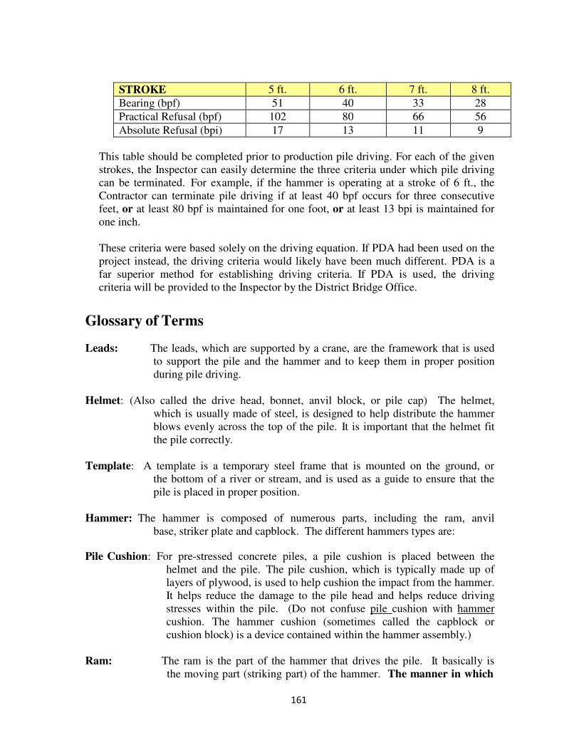
161
STROKE 5 ft. 6 ft. 7 ft. 8 ft.
Bearing (bpf) 51 40 33 28
Practical Refusal (bpf) 102 80 66 56
Absolute Refusal (bpi) 17 13 11 9
This table should be completed prior to production pile driving. For each of the given
strokes, the Inspector can easily determine the three criteria under which pile driving
can be terminated. For example, if the hammer is operating at a stroke of 6 ft., the
Contractor can terminate pile driving if at least 40 bpf occurs for three consecutive
feet, or at least 80 bpf is maintained for one foot, or at least 13 bpi is maintained for
one inch.
These criteria were based solely on the driving equation. If PDA had been used on the
project instead, the driving criteria would likely have been much different. PDA is a
far superior method for establishing driving criteria. If PDA is used, the driving
criteria will be provided to the Inspector by the District Bridge Office.
Glossary of Terms Leads: The leads, which are supported by a crane, are the framework that is used
to support the pile and the hammer and to keep them in proper position
during pile driving.
Helmet: (Also called the drive head, bonnet, anvil block, or pile cap) The helmet,
which is usually made of steel, is designed to help distribute the hammer
blows evenly across the top of the pile. It is important that the helmet fit
the pile correctly.
Template: A template is a temporary steel frame that is mounted on the ground, or
the bottom of a river or stream, and is used as a guide to ensure that the
pile is placed in proper position.
Hammer: The hammer is composed of numerous parts, including the ram, anvil
base, striker plate and capblock. The different hammers types are: Pile Cushion: For pre-stressed concrete piles, a pile cushion is placed between the
helmet and the pile. The pile cushion, which is typically made up of
layers of plywood, is used to help cushion the impact from the hammer.
It helps reduce the damage to the pile head and helps reduce driving
stresses within the pile. (Do not confuse pile cushion with hammer
cushion. The hammer cushion (sometimes called the capblock or
cushion block) is a device contained within the hammer assembly.)
Ram: The ram is the part of the hammer that drives the pile. It basically is
the moving part (striking part) of the hammer. The manner in which

162
the ram is raised and lowered is the main feature that distinguishes
the different hammer types.
Stroke: The stroke is the distance over which the ram travels as it falls (from
the highest point to the lowest point). If the ram freefalls by gravity,
the stroke is the actual distance of the fall. However, if the ram is
“pushed” downward as it travels downward, an equivalent freefall
stroke must be determined.
Energy: There are numerous ways to refer to the energy (or equivalent energy)
that a hammer imparts to a pile. The simplest way is to state that
energy is equal to the weight of the ram multiplied by the hammer
stroke [E = (W)(H)]. This relationship is only applicable to drop
hammers and single-acting hammers, not for double-acting hammers.
For double-acting hammers, an equivalent free fall stroke must be
determined based on the pressure that is built-up within the bounce
chamber of the hammer. The Contractor should provide the Inspector
with information that correlates bounce chamber pressure to equivalent
freefall stroke. For double-acting hammers, the energy is considered
“equivalent” energy because it is calculated using the equivalent
freefall stroke [Equivalent Energy = (W)(Equivalent H)]. A list of pile
hammers is provided at the end of this Section.
The previous two references to energy (E and Equivalent E) are the
terms used in the driving formulas previously presented. It should be
noted that these values do not represent the energy that actually reaches
the pile. There are numerous losses of energy that occur during each
stroke of the hammer. These losses include the friction that the ram
experiences as it travels downward and the losses that occur as the
impact energy passes from the ram (through the hammer cushion, the
helmet and pile cushion) to the top of the pile. The numbers (0.1 and
1.0) in the driving formulas represent an attempt to account for these
energy losses. On projects where PDA is used, the measured energy
will be significantly lower than the energy that is computed by
multiplying W and H, because the PDA is measuring the energy that
actually reaches the gauges mounted near the top of the pile.
Drop Hammer: This type of hammer, sometimes called a gravity hammer, involves
raising a weight (ram) by a cable and allowing the weight to freefall,
striking the pile. This type of hammer is rarely used nowadays,
primarily because it is an inefficient method of driving piles.
Additionally, if great care is not used, there is a high risk that this type
of hammer will overstress the pile causing damage during driving. The
drop hammer should only be used for low capacity piles and only with
approval of the Engineer.
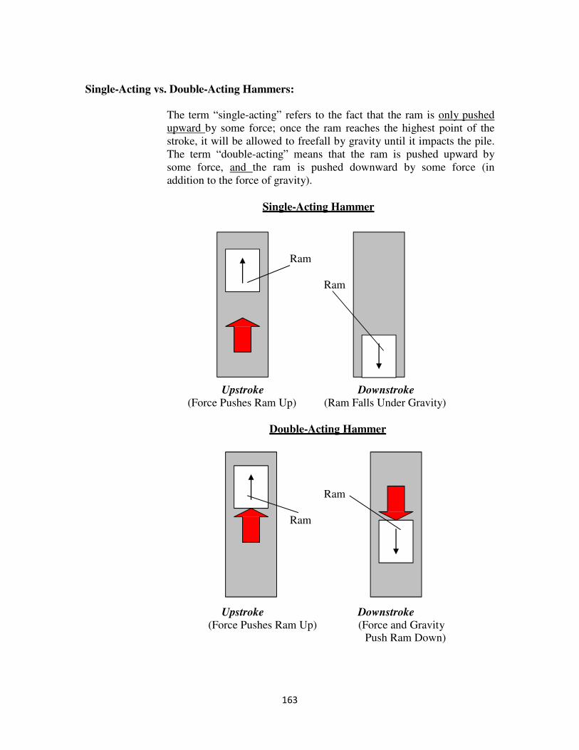
163
Single-Acting vs. Double-Acting Hammers:
The term “single-acting” refers to the fact that the ram is only pushed
upward by some force; once the ram reaches the highest point of the
stroke, it will be allowed to freefall by gravity until it impacts the pile.
The term “double-acting” means that the ram is pushed upward by
some force, and the ram is pushed downward by some force (in
addition to the force of gravity).
Single-Acting Hammer
Ram
Ram
Upstroke Downstroke (Force Pushes Ram Up) (Ram Falls Under Gravity)
Double-Acting Hammer
Ram
Ram
Upstroke Downstroke
(Force Pushes Ram Up) (Force and Gravity Push Ram Down)
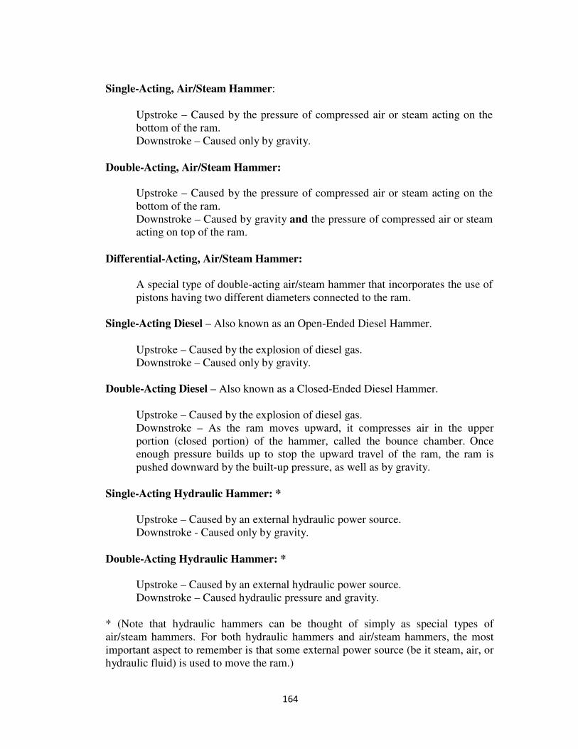
164
Single-Acting, Air/Steam Hammer:
Upstroke – Caused by the pressure of compressed air or steam acting on the
bottom of the ram.
Downstroke – Caused only by gravity.
Double-Acting, Air/Steam Hammer:
Upstroke – Caused by the pressure of compressed air or steam acting on the
bottom of the ram.
Downstroke – Caused by gravity and the pressure of compressed air or steam
acting on top of the ram.
Differential-Acting, Air/Steam Hammer:
A special type of double-acting air/steam hammer that incorporates the use of
pistons having two different diameters connected to the ram.
Single-Acting Diesel – Also known as an Open-Ended Diesel Hammer.
Upstroke – Caused by the explosion of diesel gas.
Downstroke – Caused only by gravity.
Double-Acting Diesel – Also known as a Closed-Ended Diesel Hammer.
Upstroke – Caused by the explosion of diesel gas.
Downstroke – As the ram moves upward, it compresses air in the upper
portion (closed portion) of the hammer, called the bounce chamber. Once
enough pressure builds up to stop the upward travel of the ram, the ram is
pushed downward by the built-up pressure, as well as by gravity.
Single-Acting Hydraulic Hammer: *
Upstroke – Caused by an external hydraulic power source.
Downstroke - Caused only by gravity.
Double-Acting Hydraulic Hammer: *
Upstroke – Caused by an external hydraulic power source.
Downstroke – Caused hydraulic pressure and gravity.
* (Note that hydraulic hammers can be thought of simply as special types of
air/steam hammers. For both hydraulic hammers and air/steam hammers, the most
important aspect to remember is that some external power source (be it steam, air, or
hydraulic fluid) is used to move the ram.)
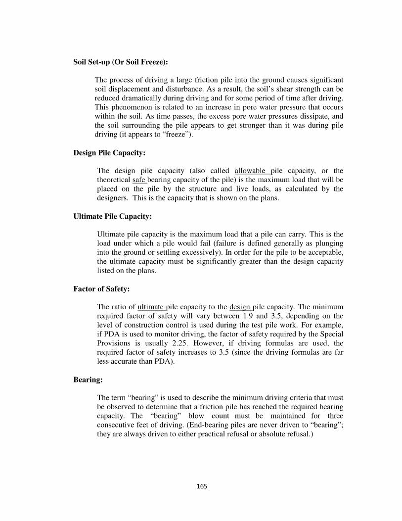
165
Soil Set-up (Or Soil Freeze):
The process of driving a large friction pile into the ground causes significant
soil displacement and disturbance. As a result, the soil’s shear strength can be
reduced dramatically during driving and for some period of time after driving.
This phenomenon is related to an increase in pore water pressure that occurs
within the soil. As time passes, the excess pore water pressures dissipate, and
the soil surrounding the pile appears to get stronger than it was during pile
driving (it appears to “freeze”).
Design Pile Capacity:
The design pile capacity (also called allowable pile capacity, or the
theoretical safe bearing capacity of the pile) is the maximum load that will be
placed on the pile by the structure and live loads, as calculated by the
designers. This is the capacity that is shown on the plans.
Ultimate Pile Capacity:
Ultimate pile capacity is the maximum load that a pile can carry. This is the
load under which a pile would fail (failure is defined generally as plunging
into the ground or settling excessively). In order for the pile to be acceptable,
the ultimate capacity must be significantly greater than the design capacity
listed on the plans.
Factor of Safety:
The ratio of ultimate pile capacity to the design pile capacity. The minimum
required factor of safety will vary between 1.9 and 3.5, depending on the
level of construction control is used during the test pile work. For example,
if PDA is used to monitor driving, the factor of safety required by the Special
Provisions is usually 2.25. However, if driving formulas are used, the
required factor of safety increases to 3.5 (since the driving formulas are far
less accurate than PDA).
Bearing:
The term “bearing” is used to describe the minimum driving criteria that must
be observed to determine that a friction pile has reached the required bearing
capacity. The “bearing” blow count must be maintained for three
consecutive feet of driving. (End-bearing piles are never driven to “bearing”;
they are always driven to either practical refusal or absolute refusal.)

166
Practical Refusal:
As defined in the Specifications, practical refusal is twice the blow count
required for bearing, maintained for one foot.
Absolute Refusal:
As defined in the Specifications, absolute refusal is four times the blow count
required for safe bearing, maintained for one inch.
Estimating the Stroke
It is very important that the hammer stroke be estimated as accurately as possible, at least
to the nearest one-foot (preferably to the nearest half-foot).
Single-acting air/steam hammers and single-acting hydraulic hammers utilize a constant
stroke depending on the available stroke settings. For example, the ICE 160-SH is a
single-acting, hydraulic hammer that has a maximum stroke of 4 ft. With this hammer,
the Contractor can set the stroke to operate at 1 ft., 2 ft., 3 ft., or 4 ft. (full stroke). If the
Contractor chooses for some reason to set the hammer to operate at half stroke, the stroke
will always be 2 ft. for that hammer. During pile driving, if the Contractor increases to
full stroke, the stroke will always be 4 ft. For these hammers, recording the stroke is
usually a simple matter.
Diesel hammers operate differently than air/steam and hydraulic hammers. Diesel
hammers have several different fuel settings that correspond to various magnitudes of
fuel combustion. These fuel settings are not absolutely linked to a specific stroke. For
diesel hammers, the stroke that is achieved during driving is directly related to the
resistance provided by the soil. In other words, for a given fuel setting, the stroke will
tend to increase as the pile penetrates into harder/stiffer ground. Conversely, as the
driving resistance decreases (meaning the pile is penetrating into looser/softer ground),
the stroke will tend to decrease.
The hammer stroke can be estimated or measured during pile driving using the following
methods:
Visual Methods: For drop hammers and single-acting hammers, the stroke can
usually be estimated by simply observing the ram. When an open-ended diesel
hammer is operating, the top of the ram often extends above the top of the hammer
(out of the open end) at the high point of each stroke. Sometimes the stroke can be
determined by viewing this part of the ram relative to the leads. In some cases, the
end of the ram has rings that provide an estimate of the stroke as the ram extends out
of the top of the hammer.
For double-acting hammers, the Contractor must provide a bounce chamber pressure
gauge and provide the relationship between bounce chamber pressure and equivalent
167
freefall stroke. For example, for a certain hammer model, if the bounce chamber
pressure is say 12 psi, the equivalent freefall stroke might be 6 ft.
Timed Methods: For single-acting diesel hammers operating continuously, it is
possible to measure the time that it takes the hammer to strike the pile 10 times, and
use this number to estimate stroke using the following equation:
H = 0.0402 (T)2
– 0.3
Where: H = stroke (ft.)
T = Time (seconds) for 10 hammer blows
For example, if a single-acting diesel hammer (operating continuously) is being used,
and it takes 12 seconds for the pile to be struck 10 times, the stroke is about 5.5 ft.
Note that this equation is only valid for single-acting diesel hammers; it is not
applicable to double-acting diesel hammers.
Some Inspectors might be concerned that, in order to use the timed method, he/she
might not be able to record the blow count that is occurring during that interval of
driving. Because obtaining stroke information is so important, it is acceptable to
miss a blow count every so often during the time at which the Inspector is checking
the stroke. For instance, for every 5 ft. to 7 ft. of pile driven, the driving record
might have a blank in the blow count column, but it would have a value in the stroke
column.
Saximeter: A saximeter operates on the same principle as the one described above;
the saximeter calculates stroke by measuring the time between blows.
Bounce Chamber Pressure: For closed-ended hammers, none of the previous
methods for estimating the stroke are appropriate, since the ram is not freefalling on
the downstroke. In these cases, a bounce chamber pressure gauge must be used to
estimate an equivalent freefall stroke. The Contractor should provide the Inspector
with information that relates the bounce chamber pressure to the equivalent freefall
stroke.
Preparation Prior to Pile Driving Prior to pile driving operations, the Inspector should do the following:
1. Download Forms C-1 and C-4 from FILE:\\0501coconst\public\FORMS
2. Become familiar with the type, size, and location of piles that are being used on
the project. Pay particular attention to the quantity and estimate lengths indicated
at each substructure unit on the plans, because these are the lengths that the
designers estimated would be necessary to support the load. Any significant
168
deviation in estimated pile length should be brought to the attention of the Area
Construction Engineer and the District Bridge Engineer.
3. If prestressed concrete piles or timber piles are used, obtain a copy of the
Contractor’s Pile Order List. Confirm that the production piles (size and length)
provided by the Contractor meet the requirements of the order list.
4. Examine the tips (bottom) of each pile to confirm that the appropriate tip (point)
has been used per the requirements of the plans and Specifications.
5. Confirm that the pile has been marked in one-foot increments so the Inspector can
determine when the driving criteria have been satisfied. For sections of pile that
will be left exposed above the ground surface, remove these marks if they detract
from the appearance of the pile.
6. Confirm that the Contractor will be lifting the pile from the ground and placing it
into the leads in an appropriate manner. This is particularly important for
prestressed concrete piles. The prestressed pile standard sheet in the plans
indicates the number and locations of pile pick-up points, and it is very important
that the Contractor adhere to these requirements. Concrete piles can be damaged
if not lifted correctly, and this damage is usually not easily detected because of
the prestressing force within the pile will tend to close small cracks that may
develop.
7. Position every pile as shown on the plans. The Contractor is responsible for pile
layouts, and the Inspector is responsible for checking these layouts.
8. Confirm that the pile is oriented correctly (either plumb or battered). If battered,
confirm that the Contractor is installing the pile at the correct batter.
9. Confirm that the Contractor is using a hammer that meets the minimum energy
and ram weight requirements that are indicated in the Specifications, listed on the
plans, and the requirements of the Special Provisions.
Observations During Pile Driving
1. Record the blow count and stroke.
2. Record all noteworthy occurrences, including pile rebound.
3. Never overdrive a pile that has attained the driving criteria, unless directed to do
so by the District Bridge Engineer. In some cases, a minimum pile tip elevation
must be reached. In some cases, if driving becomes excessive, the District Bridge
Engineer may direct or approve preboring or jetting to enable the pile to reach a
certain tip elevation.
169
4. If a pile refuses at a tip elevation that is higher than expected, this might be an
indication that an obstruction was encountered (boulder, debris, etc.). A pile that
bears on such an obstruction might not be able to carry the required load, and the
Area Construction Engineer should be contacted.
5. When driving concrete piles, the pile cushion should be examined regularly to
determine that it still meets the requirements of the Specifications.
Additional Considerations
Preboring
In some cases, the Contractor is required to prebore prior to pile installation. Preboring
involves drilling a hole with an auger throughout a portion of the depth necessary for
penetration. When friction piles are to be placed through newly constructed embankment
fill, preboring must be preformed through the fill, after which the pile is placed into the
prebored hole and driven to the required capacity. Preboring operations (other than
through embankment fills) that are not specified on the plans should be allowed only if
authorized by the District Bridge Engineer.
Jetting
Jetting is another method that is sometimes used to facilitate pile penetration, particular
projects located in the coastal region. Jetting involves the use of high-pressure water or
air that flushes away the soil adjacent to the pile. In most cases, jetting is only used to
help the pile pass through a certain stratum that it could not pass by driving alone; it is
rarely used during the entire pile installation. Jetting is most effective in loose to medium
dense granular soils.
Jetting is not advised for friction piles because the jetting process reduces the piles
frictional capacity. Recently, environmental regulations have restricted the locations at
which jetting can be used. As with preboring not called out on the plans, jetting should
only be allowed if authorized by the District Bridge Engineer.
Unusual Driving
An apparent increase (or an apparent decrease) in the driving resistance may indicate that
a pile has been broken or, in the case of cast-in-place piles, the shell may have collapsed.
This occurrence should be recorded and immediately brought to the attention of the Area
Construction Engineer. Each case will have to be evaluated as to whether remedial
actions are required.
When driving steel shells for cast-in-place concrete piles, check adjacent piles that have
been previously installed for possible shell collapse or damage as subsequent piles are
driven in the group. To the extent practical, all driving of the shells of cast-in-place piles
shall be completed for a given substructure unit prior to concrete being placed in any of
170
the piles. Driving shall not be performed within a 15-foot radius of freshly placed
concrete until the concrete has been in place for at least 7 days.
Accuracy of Driving
The Inspector should check the alignment of all piles (vertical and battered) prior to
driving, when the pile is placed within the leads. Vertical piles should be checked with a
carpenter’s level, and battered piles should be checked with a template and carpenter’s
level. When batters piles are required, the leads should be battered at the same angle as
the pile.
Piles shall not be driven with a variation of more than ¼ inch per foot from vertical or the
batter specified. This tolerance should be check immediately after the pile has been fully
driven into the ground.
Once pile driving operations begin, the Contractor and Inspector should periodically
check that the position and alignment of the pile are within tolerance. Piles have a
tendency to change position and direction once driving begins. Periodic checking may
allow the Contractor to make adjustments that can correct the position or alignment of a
pile that is beginning to deviate from its planned location and orientation.
After the piles are driven, the Inspector must make the following three checks to help
ensure that the piles meet the Specifications:
1. Each pile must be no more than ¼ inch per foot from vertical or the batter
specified on the plans (or as directed by the Engineer). This check is made
immediately after the pile is driven.
2. Each pile must be within the position tolerance as described in the Specifications
for that particular type of pile. This check is usually made after all piles within a
section of footing have been driven.
3. All piles under a separate footing or an individually constructed unit are
considered as a group and must conform to the center of gravity (C.G.) tolerances
described in the Specifications.
The following sketches, Determination of Center of Gravity of Pile Group, show a typical
steel pile layout for a bridge abutment. The upper sketch shows the locations of the piles
as indicated on the plans. The lower sketch shows the piles locations after they were
driven into the ground.
Since this foundation consists of steel piles supporting an abutment, each individual pile
must be within 6 inches of plan location. All piles satisfy this requirement.
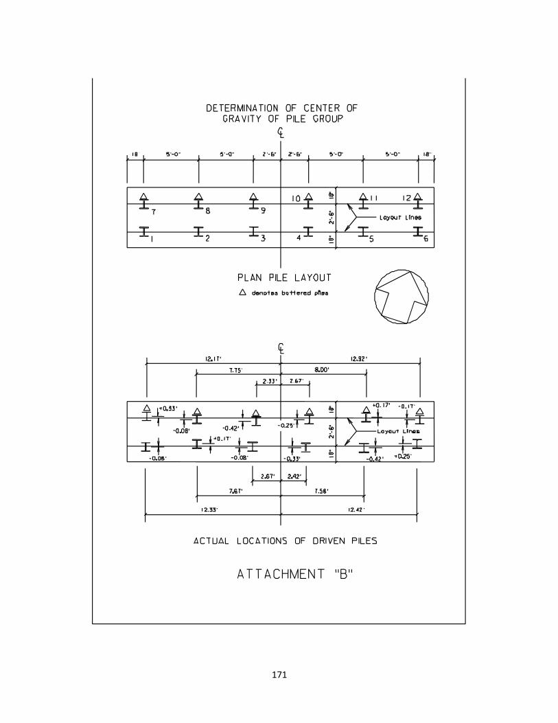
171
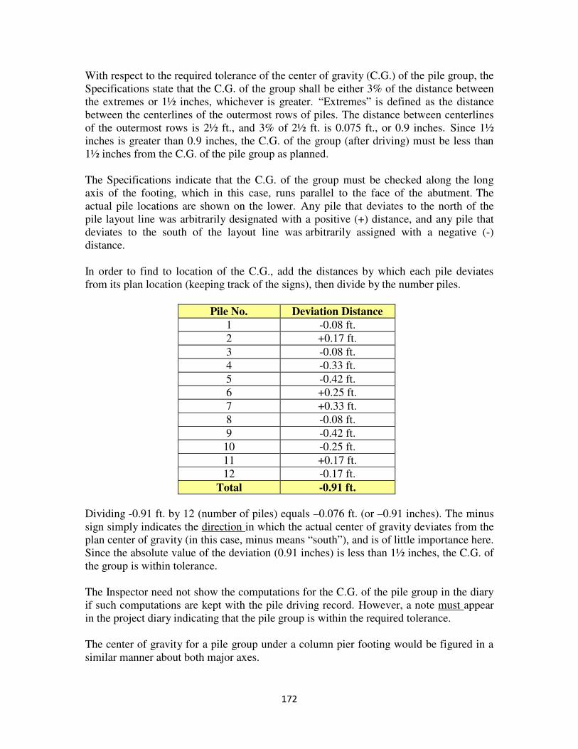
172
With respect to the required tolerance of the center of gravity (C.G.) of the pile group, the
Specifications state that the C.G. of the group shall be either 3% of the distance between
the extremes or 1½ inches, whichever is greater. “Extremes” is defined as the distance
between the centerlines of the outermost rows of piles. The distance between centerlines
of the outermost rows is 2½ ft., and 3% of 2½ ft. is 0.075 ft., or 0.9 inches. Since 1½
inches is greater than 0.9 inches, the C.G. of the group (after driving) must be less than
1½ inches from the C.G. of the pile group as planned.
The Specifications indicate that the C.G. of the group must be checked along the long
axis of the footing, which in this case, runs parallel to the face of the abutment. The
actual pile locations are shown on the lower. Any pile that deviates to the north of the
pile layout line was arbitrarily designated with a positive (+) distance, and any pile that
deviates to the south of the layout line was arbitrarily assigned with a negative (-)
distance.
In order to find to location of the C.G., add the distances by which each pile deviates
from its plan location (keeping track of the signs), then divide by the number piles.
Pile No. Deviation Distance
1 -0.08 ft.
2 +0.17 ft.
3 -0.08 ft.
4 -0.33 ft.
5 -0.42 ft.
6 +0.25 ft.
7 +0.33 ft.
8 -0.08 ft.
9 -0.42 ft.
10 -0.25 ft.
11 +0.17 ft.
12 -0.17 ft.
Total -0.91 ft.
Dividing -0.91 ft. by 12 (number of piles) equals –0.076 ft. (or –0.91 inches). The minus
sign simply indicates the direction in which the actual center of gravity deviates from the
plan center of gravity (in this case, minus means “south”), and is of little importance here.
Since the absolute value of the deviation (0.91 inches) is less than 1½ inches, the C.G. of
the group is within tolerance.
The Inspector need not show the computations for the C.G. of the pile group in the diary
if such computations are kept with the pile driving record. However, a note must appear
in the project diary indicating that the pile group is within the required tolerance.
The center of gravity for a pile group under a column pier footing would be figured in a
similar manner about both major axes.
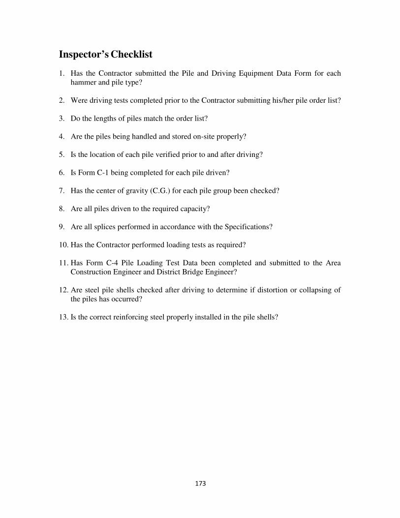
173
Inspector’s Checklist 1. Has the Contractor submitted the Pile and Driving Equipment Data Form for each
hammer and pile type?
2. Were driving tests completed prior to the Contractor submitting his/her pile order list?
3. Do the lengths of piles match the order list?
4. Are the piles being handled and stored on-site properly?
5. Is the location of each pile verified prior to and after driving?
6. Is Form C-1 being completed for each pile driven?
7. Has the center of gravity (C.G.) for each pile group been checked?
8. Are all piles driven to the required capacity?
9. Are all splices performed in accordance with the Specifications?
10. Has the Contractor performed loading tests as required?
11. Has Form C-4 Pile Loading Test Data been completed and submitted to the Area
Construction Engineer and District Bridge Engineer?
12. Are steel pile shells checked after driving to determine if distortion or collapsing of
the piles has occurred?
13. Is the correct reinforcing steel properly installed in the pile shells?
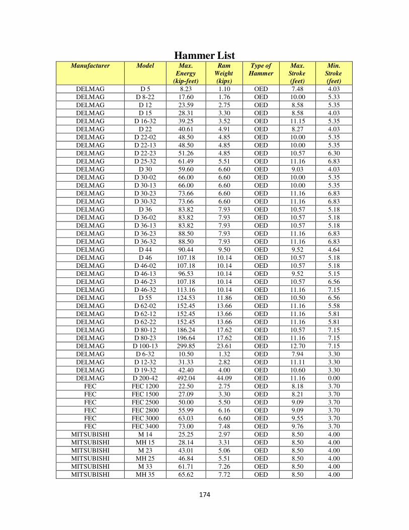
174
Hammer List Manufacturer Model Max.
Energy
(kip-feet)
Ram
Weight
(kips)
Type of
Hammer
Max.
Stroke
(feet)
Min.
Stroke
(feet)
DELMAG D 5 8.23 1.10 OED 7.48 4.03
DELMAG D 8-22 17.60 1.76 OED 10.00 5.33
DELMAG D 12 23.59 2.75 OED 8.58 5.35
DELMAG D 15 28.31 3.30 OED 8.58 4.03
DELMAG D 16-32 39.25 3.52 OED 11.15 5.35
DELMAG D 22 40.61 4.91 OED 8.27 4.03
DELMAG D 22-02 48.50 4.85 OED 10.00 5.35
DELMAG D 22-13 48.50 4.85 OED 10.00 5.35
DELMAG D 22-23 51.26 4.85 OED 10.57 6.30
DELMAG D 25-32 61.49 5.51 OED 11.16 6.83
DELMAG D 30 59.60 6.60 OED 9.03 4.03
DELMAG D 30-02 66.00 6.60 OED 10.00 5.35
DELMAG D 30-13 66.00 6.60 OED 10.00 5.35
DELMAG D 30-23 73.66 6.60 OED 11.16 6.83
DELMAG D 30-32 73.66 6.60 OED 11.16 6.83
DELMAG D 36 83.82 7.93 OED 10.57 5.18
DELMAG D 36-02 83.82 7.93 OED 10.57 5.18
DELMAG D 36-13 83.82 7.93 OED 10.57 5.18
DELMAG D 36-23 88.50 7.93 OED 11.16 6.83
DELMAG D 36-32 88.50 7.93 OED 11.16 6.83
DELMAG D 44 90.44 9.50 OED 9.52 4.64
DELMAG D 46 107.18 10.14 OED 10.57 5.18
DELMAG D 46-02 107.18 10.14 OED 10.57 5.18
DELMAG D 46-13 96.53 10.14 OED 9.52 5.15
DELMAG D 46-23 107.18 10.14 OED 10.57 6.56
DELMAG D 46-32 113.16 10.14 OED 11.16 7.15
DELMAG D 55 124.53 11.86 OED 10.50 6.56
DELMAG D 62-02 152.45 13.66 OED 11.16 5.58
DELMAG D 62-12 152.45 13.66 OED 11.16 5.81
DELMAG D 62-22 152.45 13.66 OED 11.16 5.81
DELMAG D 80-12 186.24 17.62 OED 10.57 7.15
DELMAG D 80-23 196.64 17.62 OED 11.16 7.15
DELMAG D 100-13 299.85 23.61 OED 12.70 7.15
DELMAG D 6-32 10.50 1.32 OED 7.94 3.30
DELMAG D 12-32 31.33 2.82 OED 11.11 3.30
DELMAG D 19-32 42.40 4.00 OED 10.60 3.30
DELMAG D 200-42 492.04 44.09 OED 11.16 0.00
FEC FEC 1200 22.50 2.75 OED 8.18 3.70
FEC FEC 1500 27.09 3.30 OED 8.21 3.70
FEC FEC 2500 50.00 5.50 OED 9.09 3.70
FEC FEC 2800 55.99 6.16 OED 9.09 3.70
FEC FEC 3000 63.03 6.60 OED 9.55 3.70
FEC FEC 3400 73.00 7.48 OED 9.76 3.70
MITSUBISHI M 14 25.25 2.97 OED 8.50 4.00
MITSUBISHI MH 15 28.14 3.31 OED 8.50 4.00
MITSUBISHI M 23 43.01 5.06 OED 8.50 4.00
MITSUBISHI MH 25 46.84 5.51 OED 8.50 4.00
MITSUBISHI M 33 61.71 7.26 OED 8.50 4.00
MITSUBISHI MH 35 65.62 7.72 OED 8.50 4.00
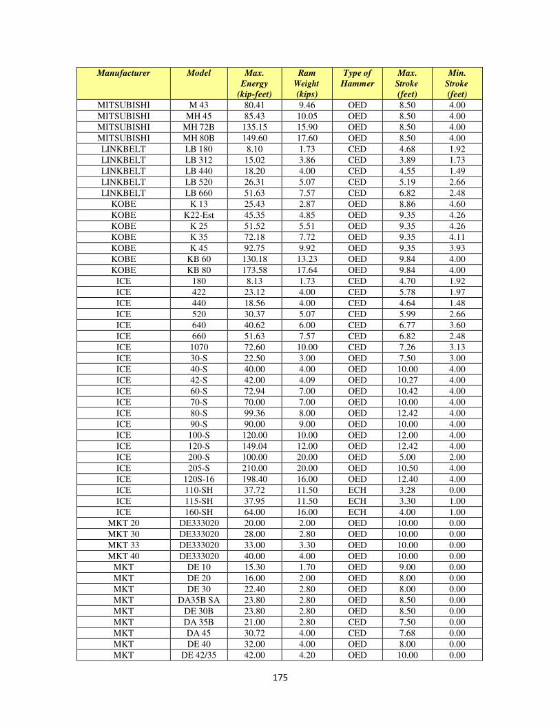
175
Manufacturer Model Max.
Energy
(kip-feet)
Ram
Weight
(kips)
Type of
Hammer
Max.
Stroke
(feet)
Min.
Stroke
(feet)
MITSUBISHI M 43 80.41 9.46 OED 8.50 4.00
MITSUBISHI MH 45 85.43 10.05 OED 8.50 4.00
MITSUBISHI MH 72B 135.15 15.90 OED 8.50 4.00
MITSUBISHI MH 80B 149.60 17.60 OED 8.50 4.00
LINKBELT LB 180 8.10 1.73 CED 4.68 1.92
LINKBELT LB 312 15.02 3.86 CED 3.89 1.73
LINKBELT LB 440 18.20 4.00 CED 4.55 1.49
LINKBELT LB 520 26.31 5.07 CED 5.19 2.66
LINKBELT LB 660 51.63 7.57 CED 6.82 2.48
KOBE K 13 25.43 2.87 OED 8.86 4.60
KOBE K22-Est 45.35 4.85 OED 9.35 4.26
KOBE K 25 51.52 5.51 OED 9.35 4.26
KOBE K 35 72.18 7.72 OED 9.35 4.11
KOBE K 45 92.75 9.92 OED 9.35 3.93
KOBE KB 60 130.18 13.23 OED 9.84 4.00
KOBE KB 80 173.58 17.64 OED 9.84 4.00
ICE 180 8.13 1.73 CED 4.70 1.92
ICE 422 23.12 4.00 CED 5.78 1.97
ICE 440 18.56 4.00 CED 4.64 1.48
ICE 520 30.37 5.07 CED 5.99 2.66
ICE 640 40.62 6.00 CED 6.77 3.60
ICE 660 51.63 7.57 CED 6.82 2.48
ICE 1070 72.60 10.00 CED 7.26 3.13
ICE 30-S 22.50 3.00 OED 7.50 3.00
ICE 40-S 40.00 4.00 OED 10.00 4.00
ICE 42-S 42.00 4.09 OED 10.27 4.00
ICE 60-S 72.94 7.00 OED 10.42 4.00
ICE 70-S 70.00 7.00 OED 10.00 4.00
ICE 80-S 99.36 8.00 OED 12.42 4.00
ICE 90-S 90.00 9.00 OED 10.00 4.00
ICE 100-S 120.00 10.00 OED 12.00 4.00
ICE 120-S 149.04 12.00 OED 12.42 4.00
ICE 200-S 100.00 20.00 OED 5.00 2.00
ICE 205-S 210.00 20.00 OED 10.50 4.00
ICE 120S-16 198.40 16.00 OED 12.40 4.00
ICE 110-SH 37.72 11.50 ECH 3.28 0.00
ICE 115-SH 37.95 11.50 ECH 3.30 1.00
ICE 160-SH 64.00 16.00 ECH 4.00 1.00
MKT 20 DE333020 20.00 2.00 OED 10.00 0.00
MKT 30 DE333020 28.00 2.80 OED 10.00 0.00
MKT 33 DE333020 33.00 3.30 OED 10.00 0.00
MKT 40 DE333020 40.00 4.00 OED 10.00 0.00
MKT DE 10 15.30 1.70 OED 9.00 0.00
MKT DE 20 16.00 2.00 OED 8.00 0.00
MKT DE 30 22.40 2.80 OED 8.00 0.00
MKT DA35B SA 23.80 2.80 OED 8.50 0.00
MKT DE 30B 23.80 2.80 OED 8.50 0.00
MKT DA 35B 21.00 2.80 CED 7.50 0.00
MKT DA 45 30.72 4.00 CED 7.68 0.00
MKT DE 40 32.00 4.00 OED 8.00 0.00
MKT DE 42/35 42.00 4.20 OED 10.00 0.00

176
Manufacturer Model Max.
Energy
(kip-feet)
Ram
Weight
(kips)
Type of
Hammer
Max.
Stroke
(feet)
Min.
Stroke
(feet)
MKT DE 50C 50.00 5.00 OED 10.00 0.00
MKT DE 70C 70.00 7.00 OED 10.00 0.00
MKT DE 50B 42.50 5.00 OED 8.50 0.00
MKT DA55B SA 40.00 5.00 OED 8.00 0.00
MKT DA 55B 38.20 5.00 CED 7.64 0.00
MKT DE 70B 59.50 7.00 OED 8.50 0.00
MKT 50 DE70/50B 50.00 5.00 OED 10.00 0.00
MKT 70 DE70/50B 70.00 7.00 OED 10.00 0.00
MKT 110 DE110150 110.00 11.00 OED 10.00 0.00
MKT 150 DE110150 150.00 15.00 OED 10.00 0.00
MKT DA 35C 21.00 2.80 CED 7.50 0.00
MKT DA 55C 38.20 5.00 CED 7.64 0.00
CONMACO C 50 15.00 5.00 ECH 3.00 0.00
CONMACO C 65 19.50 6.50 ECH 3.00 0.00
CONMACO C 550 25.00 5.00 ECH 5.00 0.00
CONMACO C 565 32.50 6.50 ECH 5.00 0.00
CONMACO C 80 26.00 8.00 ECH 3.25 0.00
CONMACO C 100 32.50 10.00 ECH 3.25 0.00
CONMACO C 115 37.38 11.50 ECH 3.25 0.00
CONMACO C 80E5 40.00 8.00 ECH 5.00 0.00
CONMACO C 100E5 50.00 10.00 ECH 5.00 0.00
CONMACO C 115E5 57.50 11.50 ECH 5.00 0.00
CONMACO C 125E5 62.50 12.50 ECH 5.00 0.00
CONMACO C 140 42.00 14.00 ECH 3.00 0.00
CONMACO C 160 48.75 16.25 ECH 3.00 0.00
CONMACO C 200 60.00 20.00 ECH 3.00 0.00
CONMACO C 300 90.00 30.00 ECH 3.00 0.00
CONMACO C 5200 100.00 20.00 ECH 5.00 0.00
CONMACO C 5300 150.00 30.00 ECH 5.00 0.00
CONMACO C 5450 225.00 45.00 ECH 5.00 0.00
CONMACO C 5700 350.00 70.00 ECH 5.00 0.00
CONMACO C 6850 510.00 85.00 ECH 6.00 0.00
CONMACO C 160 51.78 17.26 ECH 3.00 0.00
VULCAN VUL V12 27.11 2.76 OED 9.84 5.58
VULCAN VUL V18 39.05 3.97 OED 9.84 5.58
VULCAN VUL V25 57.88 5.51 OED 10.50 5.58
VULCAN VUL 01 15.00 5.00 ECH 3.00 3.00
VULCAN VUL 02 7.26 3.00 ECH 2.42 2.42
VULCAN VUL 06 19.50 6.50 ECH 3.00 3.00
VULCAN VUL 08 26.00 8.00 ECH 3.25 3.25
VULCAN VUL 010 32.50 10.00 ECH 3.25 3.25
VULCAN VUL 012 39.00 12.00 ECH 3.25 3.25
VULCAN VUL 014 42.00 14.00 ECH 3.00 3.00
VULCAN VUL 016 48.75 16.25 ECH 3.00 3.00
VULCAN VUL 020 60.00 20.00 ECH 3.00 3.00
VULCAN VUL 030 90.00 30.00 ECH 3.00 3.00
VULCAN VUL 040 120.00 40.00 ECH 3.00 3.00
VULCAN VUL 060 180.00 60.00 ECH 3.00 3.00
VULCAN VUL 30C 7.26 3.00 ECH 2.42 0.00
VULCAN VUL 50C 15.10 5.00 ECH 3.02 1.36
VULCAN VUL 65C 19.18 6.50 ECH 2.95 0.00
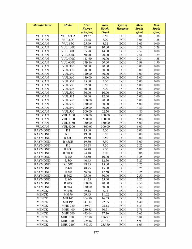
177
Manufacturer Model Max.
Energy
(kip-feet)
Ram
Weight
(kips)
Type of
Hammer
Max.
Stroke
(feet)
Min.
Stroke
(feet)
VULCAN VUL 65CA 19.57 6.50 ECH 3.01 1.38
VULCAN VUL 80C 24.48 8.00 ECH 3.06 1.38
VULCAN VUL 85C 25.99 8.52 ECH 3.05 0.00
VULCAN VUL 100C 32.90 10.00 ECH 3.29 3.29
VULCAN VUL 140C 35.98 14.00 ECH 2.57 0.00
VULCAN VUL 200C 50.20 20.00 ECH 2.51 1.29
VULCAN VUL 400C 113.60 40.00 ECH 2.84 1.38
VULCAN VUL 600C 179.16 60.00 ECH 2.99 1.50
VULCAN VUL 320 60.00 20.00 ECH 3.00 0.00
VULCAN VUL 330 90.00 30.00 ECH 3.00 0.00
VULCAN VUL 340 120.00 40.00 ECH 3.00 0.00
VULCAN VUL 360 180.00 60.00 ECH 3.00 0.00
VULCAN VUL 505 25.00 5.00 ECH 5.00 0.00
VULCAN VUL 506 32.50 6.50 ECH 5.00 0.00
VULCAN VUL 508 40.00 8.00 ECH 5.00 0.00
VULCAN VUL 510 50.00 10.00 ECH 5.00 0.00
VULCAN VUL 512 60.00 12.00 ECH 5.00 5.00
VULCAN VUL 520 100.00 20.00 ECH 5.00 0.00
VULCAN VUL 530 150.00 30.00 ECH 5.00 0.00
VULCAN VUL 540 200.00 40.90 ECH 4.89 0.00
VULCAN VUL 560 300.00 62.50 ECH 4.80 0.00
VULCAN VUL 3100 300.00 100.00 ECH 3.00 0.00
VULCAN VUL 5100 500.00 100.00 ECH 5.00 0.00
VULCAN VUL 5150 750.00 150.00 ECH 5.00 0.00
VULCAN VUL 6300 1800.00 300.00 ECH 6.00 0.00
RAYMOND R 1 15.00 5.00 ECH 3.00 0.00
RAYMOND R 15 19.50 6.50 ECH 3.00 0.00
RAYMOND R 65C 19.50 6.50 ECH 3.00 0.00
RAYMOND R 65CH 19.50 6.50 ECH 3.00 0.00
RAYMOND R 0 24.38 7.50 ECH 3.25 0.00
RAYMOND R 80C 24.48 8.00 ECH 3.06 0.00
RAYMOND R 80CH 24.48 8.00 ECH 3.06 0.00
RAYMOND R 2/0 32.50 10.00 ECH 3.25 0.00
RAYMOND R 3/0 40.63 12.50 ECH 3.25 0.00
RAYMOND R 150C 48.75 15.00 ECH 3.25 0.00
RAYMOND R 4/0 48.75 15.00 ECH 3.25 0.00
RAYMOND R 5/0 56.88 17.50 ECH 3.25 0.00
RAYMOND R 30X 75.00 30.00 ECH 2.50 0.00
RAYMOND R 8/0 81.25 25.00 ECH 3.25 0.00
RAYMOND R 40X 100.00 40.00 ECH 2.50 0.00
RAYMOND R 60X 150.00 60.00 ECH 2.50 0.00
MENCK MH 68 49.18 7.72 ECH 6.37 0.00
MENCK MH 96 69.43 11.02 ECH 6.30 0.00
MENCK MH 145 104.80 16.53 ECH 6.34 0.00
MENCK MH 195 141.12 22.05 ECH 6.40 0.00
MENCK MHU 220 159.07 25.13 ECH 6.33 0.00
MENCK MHU 400 289.55 50.71 ECH 5.71 0.00
MENCK MHU 600 433.64 77.16 ECH 5.62 0.00
MENCK MHU 1000 737.70 126.97 ECH 5.81 0.00
MENCK MHU 1700 1228.87 207.23 ECH 5.93 0.00
MENCK MHU 2100 1547.59 255.80 ECH 6.05 0.00
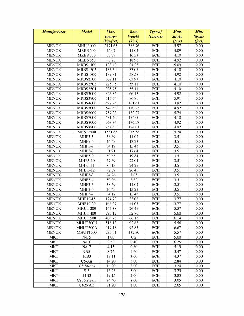
178
Manufacturer Model Max.
Energy
(kip-feet)
Ram
Weight
(kips)
Type of
Hammer
Max.
Stroke
(feet)
Min.
Stroke
(feet)
MENCK MHU 3000 2171.65 363.76 ECH 5.97 0.00
MENCK MRBS 500 45.07 11.02 ECH 4.09 0.00
MENCK MRBS 750 67.77 16.53 ECH 4.10 0.00
MENCK MRBS 850 93.28 18.96 ECH 4.92 0.00
MENCK MRBS1100 123.43 24.25 ECH 5.09 0.00
MENCK MRBS1502 135.59 33.07 ECH 4.10 0.00
MENCK MRBS1800 189.81 38.58 ECH 4.92 0.00
MENCK MRBS2500 262.11 63.93 ECH 4.10 0.00
MENCK MRBS2502 225.95 55.11 ECH 4.10 0.00
MENCK MRBS2504 225.95 55.11 ECH 4.10 0.00
MENCK MRBS3000 325.36 66.13 ECH 4.92 0.00
MENCK MRBS3900 513.34 86.86 ECH 5.91 0.00
MENCK MRBS4600 498.94 101.41 ECH 4.92 0.00
MENCK MRBS5000 542.33 110.23 ECH 4.92 0.00
MENCK MRBS6000 759.23 132.27 ECH 5.74 0.00
MENCK MRBS7000 631.40 154.00 ECH 4.10 0.00
MENCK MRBS8000 867.74 176.37 ECH 4.92 0.00
MENCK MRBS8800 954.53 194.01 ECH 4.92 0.00
MENCK MBS12500 1581.83 275.58 ECH 5.74 0.00
MENCK MHF5-5 38.69 11.02 ECH 3.51 0.00
MENCK MHF5-6 46.43 13.23 ECH 3.51 0.00
MENCK MHF5-7 54.17 15.43 ECH 3.51 0.00
MENCK MHF5-8 61.91 17.64 ECH 3.51 0.00
MENCK MHF5-9 69.65 19.84 ECH 3.51 0.00
MENCK MHF5-10 77.39 22.04 ECH 3.51 0.00
MENCK MHF5-11 85.13 24.25 ECH 3.51 0.00
MENCK MHF5-12 92.87 26.45 ECH 3.51 0.00
MENCK MHF3-3 24.76 7.05 ECH 3.51 0.00
MENCK MHF3-4 30.96 8.82 ECH 3.51 0.00
MENCK MHF3-5 38.69 11.02 ECH 3.51 0.00
MENCK MHF3-6 46.43 13.23 ECH 3.51 0.00
MENCK MHF3-7 54.17 15.43 ECH 3.51 0.00
MENCK MHF10-15 124.73 33.06 ECH 3.77 0.00
MENCK MHF10-20 166.27 44.07 ECH 3.77 0.00
MENCK MHUT 200 147.38 26.46 ECH 5.57 0.00
MENCK MHUT 400 295.12 52.70 ECH 5.60 0.00
MENCK MHUT 500 405.75 66.13 ECH 6.14 0.00
MENCK MHUT700U 516.13 92.83 ECH 5.56 0.00
MENCK MHUT700A 619.18 92.83 ECH 6.67 0.00
MENCK MHUT1000 736.91 132.30 ECH 5.57 0.00
MKT No. 5 1.00 0.2 ECH 5.00 0.00
MKT No. 6 2.50 0.40 ECH 6.25 0.00
MKT No. 7 4.15 0.80 ECH 5.19 0.00
MKT 9B3 8.75 1.60 ECH 5.47 0.00
MKT 10B3 13.11 3.00 ECH 4.37 0.00
MKT C5-Air 14.20 5.00 ECH 2.84 0.00
MKT C5-Steam 16.20 5.00 ECH 3.24 0.00
MKT S-5 16.25 5.00 ECH 3.25 0.00
MKT 11B3 19.15 5.00 ECH 3.83 0.00
MKT C826 Steam 24.40 8.00 ECH 3.05 0.00
MKT C826 Air 21.20 8.00 ECH 2.65 0.00
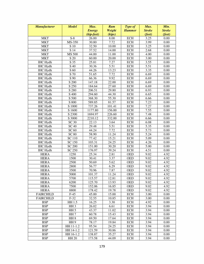
179
Manufacturer Model Max.
Energy
(kip-feet)
Ram
Weight
(kips)
Type of
Hammer
Max.
Stroke
(feet)
Min.
Stroke
(feet)
MKT S-8 26.00 8.00 ECH 3.25 0.00
MKT MS-350 30.80 7.72 ECH 3.99 0.00
MKT S 10 32.50 10.00 ECH 3.25 0.00
MKT S 14 37.52 14.00 ECH 2.68 0.00
MKT MS 500 44.00 11.00 ECH 4.00 0.00
MKT S 20 60.00 20.00 ECH 3.00 0.00
IHC Hydh S 35 25.81 7.27 ECH 3.55 0.00
IHC Hydh S 40 30.36 5.51 ECH 5.51 0.00
IHC Hydh S 60 44.26 13.23 ECH 3.35 0.00
IHC Hydh S 70 51.65 7.72 ECH 6.69 0.00
IHC Hydh S 90 66.36 9.92 ECH 6.69 0.00
IHC Hydh S 200 147.18 22.00 ECH 6.69 0.00
IHC Hydh S 250 184.64 27.60 ECH 6.69 0.00
IHC Hydh S 280 206.51 29.80 ECH 6.93 0.00
IHC Hydh S 400 294.60 44.30 ECH 6.65 0.00
IHC Hydh S 500 368.30 55.30 ECH 6.66 0.00
IHC Hydh S 800 589.85 81.57 ECH 7.23 0.00
IHC Hydh S 1000 737.26 101.41 ECH 7.27 0.00
IHC Hydh S 1600 1177.80 156.00 ECH 7.55 0.00
IHC Hydh S 2300 1694.97 226.60 ECH 7.48 0.00
IHC Hydh S 3000 2210.12 332.00 ECH 6.66 0.00
IHC Hydh SC 30 22.13 3.64 ECH 6.08 0.00
IHC Hydh SC 40 29.48 5.51 ECH 5.35 0.00
IHC Hydh SC 60 44.24 7.72 ECH 5.73 0.00
IHC Hydh SC 80 58.90 11.24 ECH 5.24 0.00
IHC Hydh SC 110 77.42 15.21 ECH 5.09 0.00
IHC Hydh SC 150 103.31 24.25 ECH 4.26 0.00
IHC Hydh SC 200 151.00 30.20 ECH 5.00 0.00
IHC Hydh SC 250 176.97 39.24 ECH 4.51 0.00
HERA 1250 25.34 2.81 OED 9.02 4.92
HERA 1500 30.41 3.37 OED 9.02 4.92
HERA 2500 50.69 5.62 OED 9.02 4.92
HERA 2800 56.77 6.29 OED 9.02 4.92
HERA 3500 70.96 7.87 OED 9.02 4.92
HERA 5000 101.37 11.24 OED 9.02 4.92
HERA 5700 115.57 12.81 OED 9.02 4.92
HERA 6200 125.70 13.93 OED 9.02 4.92
HERA 7500 152.06 16.85 OED 9.02 4.92
HERA 8800 178.42 19.78 OED 9.02 4.92
FAIRCHILD F-45 45.00 15.00 ECH 3.00 0.00
FAIRCHILD F-32 32.55 10.85 ECH 3.00 0.00
BSP HH 1.5 16.25 3.30 ECH 4.92 0.00
BSP HH 3 26.02 6.61 ECH 3.94 0.00
BSP HH 5 43.37 11.02 ECH 3.94 0.00
BSP HH 7 60.78 15.43 ECH 3.94 0.00
BSP HH 8 69.50 17.64 ECH 3.94 0.00
BSP HH 9 78.17 19.84 ECH 3.94 0.00
BSP HH 11-1.2 95.54 24.25 ECH 3.94 0.00
BSP HH 14-1.2 121.59 30.86 ECH 3.94 0.00
BSP HH 16-1.2 138.87 35.27 ECH 3.94 0.00
BSP HH 20 173.58 44.09 ECH 3.94 0.00
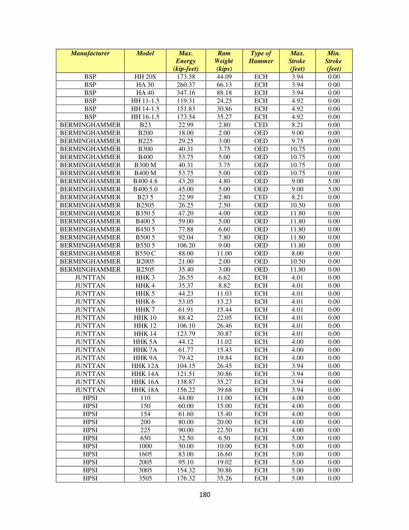
180
Manufacturer Model Max.
Energy
(kip-feet)
Ram
Weight
(kips)
Type of
Hammer
Max.
Stroke
(feet)
Min.
Stroke
(feet)
BSP HH 20S 173.58 44.09 ECH 3.94 0.00
BSP HA 30 260.37 66.13 ECH 3.94 0.00
BSP HA 40 347.16 88.18 ECH 3.94 0.00
BSP HH 11-1.5 119.31 24.25 ECH 4.92 0.00
BSP HH 14-1.5 151.83 30.86 ECH 4.92 0.00
BSP HH 16-1.5 173.54 35.27 ECH 4.92 0.00
BERMINGHAMMER B23 22.99 2.80 CED 8.21 0.00
BERMINGHAMMER B200 18.00 2.00 OED 9.00 0.00
BERMINGHAMMER B225 29.25 3.00 OED 9.75 0.00
BERMINGHAMMER B300 40.31 3.75 OED 10.75 0.00
BERMINGHAMMER B400 53.75 5.00 OED 10.75 0.00
BERMINGHAMMER B300 M 40.31 3.75 OED 10.75 0.00
BERMINGHAMMER B400 M 53.75 5.00 OED 10.75 0.00
BERMINGHAMMER B400 4.8 43.20 4.80 OED 9.00 5.00
BERMINGHAMMER B400 5.0 45.00 5.00 OED 9.00 5.00
BERMINGHAMMER B23 5 22.99 2.80 CED 8.21 0.00
BERMINGHAMMER B2505 26.25 2.50 OED 10.50 0.00
BERMINGHAMMER B350 5 47.20 4.00 OED 11.80 0.00
BERMINGHAMMER B400 5 59.00 5.00 OED 11.80 0.00
BERMINGHAMMER B450 5 77.88 6.60 OED 11.80 0.00
BERMINGHAMMER B500 5 92.04 7.80 OED 11.80 0.00
BERMINGHAMMER B550 5 106.20 9.00 OED 11.80 0.00
BERMINGHAMMER B550 C 88.00 11.00 OED 8.00 0.00
BERMINGHAMMER B2005 21.00 2.00 OED 10.50 0.00
BERMINGHAMMER B2505 35.40 3.00 OED 11.80 0.00
JUNTTAN HHK 3 26.55 6.62 ECH 4.01 0.00
JUNTTAN HHK 4 35.37 8.82 ECH 4.01 0.00
JUNTTAN HHK 5 44.23 11.03 ECH 4.01 0.00
JUNTTAN HHK 6 53.05 13.23 ECH 4.01 0.00
JUNTTAN HHK 7 61.91 15.44 ECH 4.01 0.00
JUNTTAN HHK 10 88.42 22.05 ECH 4.01 0.00
JUNTTAN HHK 12 106.10 26.46 ECH 4.01 0.00
JUNTTAN HHK 14 123.79 30.87 ECH 4.01 0.00
JUNTTAN HHK 5A 44.12 11.02 ECH 4.00 0.00
JUNTTAN HHK 7A 61.77 15.43 ECH 4.00 0.00
JUNTTAN HHK 9A 79.42 19.84 ECH 4.00 0.00
JUNTTAN HHK 12A 104.15 26.45 ECH 3.94 0.00
JUNTTAN HHK 14A 121.51 30.86 ECH 3.94 0.00
JUNTTAN HHK 16A 138.87 35.27 ECH 3.94 0.00
JUNTTAN HHK 18A 156.22 39.68 ECH 3.94 0.00
HPSI 110 44.00 11.00 ECH 4.00 0.00
HPSI 150 60.00 15.00 ECH 4.00 0.00
HPSI 154 61.60 15.40 ECH 4.00 0.00
HPSI 200 80.00 20.00 ECH 4.00 0.00
HPSI 225 90.00 22.50 ECH 4.00 0.00
HPSI 650 32.50 6.50 ECH 5.00 0.00
HPSI 1000 50.00 10.00 ECH 5.00 0.00
HPSI 1605 83.00 16.60 ECH 5.00 0.00
HPSI 2005 95.10 19.02 ECH 5.00 0.00
HPSI 3005 154.32 30.86 ECH 5.00 0.00
HPSI 3505 176.32 35.26 ECH 5.00 0.00
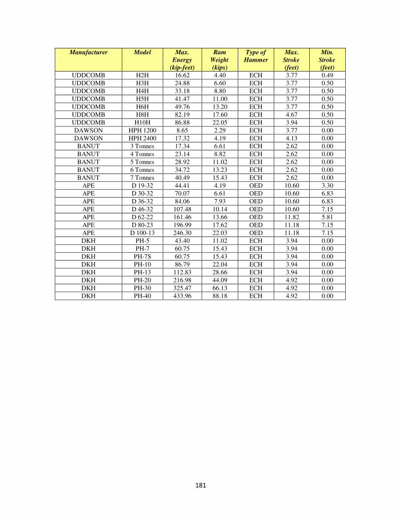
181
Manufacturer Model Max.
Energy
(kip-feet)
Ram
Weight
(kips)
Type of
Hammer
Max.
Stroke
(feet)
Min.
Stroke
(feet)
UDDCOMB H2H 16.62 4.40 ECH 3.77 0.49
UDDCOMB H3H 24.88 6.60 ECH 3.77 0.50
UDDCOMB H4H 33.18 8.80 ECH 3.77 0.50
UDDCOMB H5H 41.47 11.00 ECH 3.77 0.50
UDDCOMB H6H 49.76 13.20 ECH 3.77 0.50
UDDCOMB H8H 82.19 17.60 ECH 4.67 0.50
UDDCOMB H10H 86.88 22.05 ECH 3.94 0.50
DAWSON HPH 1200 8.65 2.29 ECH 3.77 0.00
DAWSON HPH 2400 17.32 4.19 ECH 4.13 0.00
BANUT 3 Tonnes 17.34 6.61 ECH 2.62 0.00
BANUT 4 Tonnes 23.14 8.82 ECH 2.62 0.00
BANUT 5 Tonnes 28.92 11.02 ECH 2.62 0.00
BANUT 6 Tonnes 34.72 13.23 ECH 2.62 0.00
BANUT 7 Tonnes 40.49 15.43 ECH 2.62 0.00
APE D 19-32 44.41 4.19 OED 10.60 3.30
APE D 30-32 70.07 6.61 OED 10.60 6.83
APE D 36-32 84.06 7.93 OED 10.60 6.83
APE D 46-32 107.48 10.14 OED 10.60 7.15
APE D 62-22 161.46 13.66 OED 11.82 5.81
APE D 80-23 196.99 17.62 OED 11.18 7.15
APE D 100-13 246.30 22.03 OED 11.18 7.15
DKH PH-5 43.40 11.02 ECH 3.94 0.00
DKH PH-7 60.75 15.43 ECH 3.94 0.00
DKH PH-7S 60.75 15.43 ECH 3.94 0.00
DKH PH-10 86.79 22.04 ECH 3.94 0.00
DKH PH-13 112.83 28.66 ECH 3.94 0.00
DKH PH-20 216.98 44.09 ECH 4.92 0.00
DKH PH-30 325.47 66.13 ECH 4.92 0.00
DKH PH-40 433.96 88.18 ECH 4.92 0.00
182
SECTION 404 - HYDRAULIC CEMENT CONCRETE
OPERATIONS
General Prior to placement of Hydraulic Cement Concrete, the Inspector must verify that a current
mix deign is on file for the class of concrete to be used. Concrete should be visually
inspected to ensure it is mixed properly. The Inspector should then refer to Table II-17 of
the Specifications to determine the minimum and maximum allowable air content and
consistency (slump). The Inspector should also verify that the temperature of the
concrete is within the limits specified. Attention must be paid to the batch time versus
the placement time to ensure the concrete is placed within the maximum allowable time
range for the temperature of the concrete. Concrete that does not meet the Specifications
will be rejected and removed from the project.
Materials After checking all equipment to be used, the Inspector should make those periodic checks
necessary to ensure that all materials used are within the Specifications limits and that the
concrete conforms to the requirements of the structure design.
Forms Bridge decks shall be constructed in such a manner that the actual thickness is not less
than the design thickness and not more than 1/2 inch more than the design thickness.
Before placing concrete, forms must be completely checked for conformance with the
plans and Specifications, and all irregularities corrected. Forms should also be checked
for ease of removal without injury to the concrete.
Inspectors should verify the dimensions of the forms, proper placement of reinforcing
steel and proper location of chamfer strips.
Placement and Consolidation During the placement of concrete, the Inspector must check the consistency of the
concrete and methods of spreading and consolidation. Forms are to be closely inspected
for leaks, and when discovered, must be caulked immediately.
Construction Joints Construction joints are to be made only where located on the plans, unless otherwise
specified or approved by the Engineer.
183
Unless otherwise specified, construction joints adjacent to earth fill are to be protected by
dampproofing applied for a distance of 3 inches on each side of the joint throughout the
length of the joint. This practice is intended for construction joints placed in reinforced
abutments and thin wall sections of box culverts. An approved waterstop is to be used in
visually exposed areas.
A construction joint may be placed at the junction between a footing and an abutment or
column, although such joints are not generally detailed on the plans.
Bonding Construction Joints
When placing fresh concrete against that which already has set, the old concrete is to be
thoroughly cleaned, roughened, and saturated before placing the new concrete.
Shear keys or inclined reinforcement are to be used as specified to tie various sections
together.
An epoxy bonding compound (Type EP-4) is to be applied to the face of the construction
joint in bridge decks immediately preceding the placement of adjoining concrete unless
otherwise specified.
Removal of Forms and Construction of Superimposed
Elements
The Specifications regulate the minimum time that concrete forms must remain in place
and the time that must elapse before structural steel or prestressed members may be
erected. This time is based on days when the temperature is above 400
F in the shade. If
the Contractor desires, test cylinders can be made according to accepted practice and
cured in the same manner as the structure. The results of strength tests performed on the
test cylinders will determine when the concrete forms can be removed. Particular care
should be taken to see that bridge decks are not loaded with construction equipment prior
to the attainment of the design strength.
Curing of Concrete
The Contractor shall perform evaporation rate testing prior to placement of the concrete.
The proper curing of concrete requires the proper control of four major factors:
Humidity, temperature, wind and protection against disturbance. The concrete is to be
cured under conditions of humidity, temperature, and wind that will produce a uniform
hydration of the cement. Concrete may be satisfactorily cured by either a moisture
application system or by the uniform application of an acceptable curing compound
membrane. Do not permit the use of curing compound if an overlay will be required for
additional surfacing.
184
Bridge Deck Curing
Bridge deck concrete shall be moist cured with white polyethylene sheeting with or
without the use of wet burlap. The concrete shall be maintained in a moist condition by
fogging after screeding and until covered with the white polyethylene sheeting. The
concrete surface shall stay wet under the white polyethylene sheeting until the end of the
moist-curing period. The moist-curing period shall be for at least 7 days and until 70
percent concrete strength (f ’c) is achieved. The initial temperature of the outermost
surfaces of the concrete mass shall be above 50 degrees F for at least 72 hours and above
32 degrees F until the completion of the moist-curing period. When the white
polyethylene sheeting is removed, burlap (if used) shall be removed also. White
pigmented curing compound shall be applied at the rate of 100 to 150 square feet per
gallon while the surface of the concrete deck is damp and free of standing water. Bridge
deck overlay concrete shall be cured in accordance with the requirements of Section 412
of the Specifications.
Protection of Concrete
The Contractor is to make every reasonable effort to protect the concrete from rain or
rapid drying conditions. The concrete surface is not to be walked upon or disturbed for a
minimum of 24 hours. When open-flame heaters are used in the vicinity of combustible
concrete formwork, a watchman is to be provided by the Contractor.
Hot Weather Concrete Placement
Hot weather can have many adverse effects on concrete. Some effects of hot weather on
fresh concrete include an increased water demand, an increased rate of slump, an
increased rate of setting, an increased tendency for plastic shrinkage cracking and an
increased rate in controlling entrained air content. Some effects of hot weather on
hardened concrete include a decreased 28-day strength, an increased tendency for drying
shrinkage and thermal cracking, decreased durability, greater variability of surface
appearance, an increased potential for reinforcing steel corrosion, and increased
permeability. All of these effects can compromise the strength and durability of the
concrete.
Several precautions can limit the damaging effects of hot weather on concrete. The
mixing water can be kept cool, or ice should be used. Do not add water at the project site
to compensate for a loss in slump. Prior to placement, cool all handling equipment by
wetting them with cool water. Mist forms, reinforcing steel and subgrade with cool water
immediately prior to placement. The hours of placement can be limited to the cooler
hours of the day. Placement at night allows for the concrete to attain its primary set
before the heat of the next day. Avoid delays during placement. Following placement,
sunscreens can be erected to control the surface temperature. Adequate curing is critical.
Continuous moist curing should begin as soon as surfaces are finished and should
continue for at least 24 hours.
185
Expansion and Fixed Joints
A. Open and Filled Joints
All joints should be made by the insertion and subsequent removal of a wood strip
or other material. A common tendency of concrete finishers is to plaster over the
wooden strip when finishing the joint. Proper attention should be directed to this
very important detail. The edges of all joints should be tooled to a radius of 1/4"
unless otherwise specified.
Joints are often damaged by construction traffic. Steel wheeled rollers and other
construction equipment can cause spalls at the edges of unprotected joints. Once
broken, these edges can never be satisfactorily repaired. Joints should be kept
clean and free of dirt, pebbles and other incompressible materials in order that the
openings may partially close during expansion of adjoining units of concrete.
All joints are to be completely cleaned immediately prior to filling and sealing.
Remove water and other material that may have collected in the joint. The
Specifications outline the proper procedure to follow when sealing a joint.
Poured or extruded joint sealers are to be installed slightly lower than the deck
surface (1/4" to 3/8") so that traffic does not damage the joint material. Only
tested and approved joint materials are to be used.
B. Steel Joints
Joint openings are given on bridge plans for a design temperature of 60° F.
Should the joint be set at a temperature other than 60° F, a correction must be
applied to the width of the opening. The coefficient of expansion for steel is
0.0000065 (unit per unit of length) per degree Fahrenheit. For example, a joint
opening is given as 1 1/2" at 60° F and the sum of the distances each side of this
joint to the fixed ends in adjacent spans are 165 feet. Assume the temperature to
be 95° F at the time when this joint is positioned. The correction to be made to
this opening would be found by multiplying the difference in degrees temperature
times the length of the bridge between fixed bearing times the coefficient of
expansion of steel. That is (95° - 60°) x 165' x 0.0000065 per degree equals 35 x
165' x 0.0000065 per degree Fahrenheit equals 0.038' which equals 0.456" which
equals 7/16 inch. This correction should be deducted from the plan opening.
Likewise, if the temperature at which the joint is positioned is lower than that
specified on the plans, the correction should be added to the joint opening to give
the specified opening at the plan temperature.
When positioning the rocker assembly under steel beams, the same temperature
corrections are to be used to compute the position of the arm. A standard
temperature at which the arm must be vertical will be specified on the plans. All
calculations are to be based on this standard temperature.
186
Bearing Areas It is absolutely essential that bridge seats, (that is the bearing areas of the beams and
bearing plates), be in strict compliance with the Specifications to avoid failures that may
arise from the load being concentrated on only a portion of the pad. Bridge seat bearing
areas shall be finished plane and level and shall not deviate more than 1/16 inch from plane
or more than 1/32 inch per foot from level or from the slope specified on the plans.
Precautions should be taken during the construction of bridge seats to ensure that they are
within Specification tolerance. Prior to setting the beams, the bridge seats should be
rechecked and deviations corrected if necessary, by grinding and the use of an epoxy
mortar.
Metal bearing plates and the bottoms of prefabricated beams, which are to bear on
elastomeric pads, must be coated with an approved epoxy adhesive and surfaced with an
approved grit. Bridge seats are to be finished to an equivalent roughness.
The intent regarding bridge seats is that a normal floated surface will afford the required
roughness (texture). However, in the event the surface was given a slick troweled finish
or in the event the seat had to be ground down or built up and such corrective work
resulted in a slick surface, the seats would then have to be coated with epoxy and grit in
the same manner in which the bearing plates and bottoms of prefabricated beams were
coated.
The differential height between each bridge seat is more critical than the elevation of
each seat. This is one of the factors that determine the bolster thickness of concrete in the
deck and the ease in erection of structural steel members. Once the elevation of one seat
is established in the field, that seat should be used as a bench mark for establishing the
remaining seats for that pier or abutment.
A sufficient number of depth probes must be taken while the concrete is still plastic to
determine the actual thickness of the bridge deck. A minimum of twelve probes should
be taken (more on long spans or in unusual conditions). The points to be probed are to be
selected at random and recorded in the project records; however, depth probes are not to
be taken over beams with the bolster thickness subtracted from this depth to obtain the
apparent depth. When corrugated metal deck forms are used, the Inspector should
exercise special care to insure that the depth probes are actually taken and measured from
the top of the corrugations.
Finishing Concrete Surfaces A. Class 2, Rubbed Finish
187
The face form for bridge deck sidewalks and brush curbs should be removed as
soon as the concrete will stand without support of the form and the concrete
rubbed prior to initial setting.
For other concrete surfaces requiring a rubbed finish, rubbing should begin as
soon as possible after the forms are removed. The surfaces must be thoroughly
saturated with water for at least 3 hours immediately prior to rubbing and kept
saturated during the rubbing operations.
A common tendency is to use too much mortar in the rubbing operation. The
excess mortar washes or chips off soon after construction, resulting in an
unsightly appearance. Permit the use of only enough mortar to fill the voids on
the surface.
B. Class 6, Bridge Deck Finish
The Specifications require the Contractor to provide access "for the purpose of
finishing, straight edging, making corrections, and for other operations requiring
access to the surface of the deck before grooving the deck surface." This access is
provided by a separate work bridge. The start of bridge deck placement should
not be approved until all necessary equipment is available and assurance has been
obtained from the Contractor that he will utilize such equipment as specified.
The ability to straightedge accurately is primarily based on practice and intuition.
It is not by any means an exact science. Before attempting any straightedging,
check the straightedge to be certain it is straight. Light straightedges warp and
wear easily. To make them totally warp resistant would add too much weight to
the straightedge.
When checking a straightedge, lay it on a flat surface with the edge that will be
used to check the concrete facing up. Using three blocks of equal thickness, place
one of these on each end of the straightedge. Stretch a string line taut and rest it
on top of the blocks. If the straightedge is straight, the third block should just
clear the space between the edge and the line at any point along the edge.
If the block will not slip between the line and the straightedge, there is a hump at
that location. If there is space between the block and the line, there is a sag in the
staightedge at that location. After you are assured the straightedge is straight, the
straightedge operation can begin.
Sweep the area to be checked so that it is free of dirt or other debris. Next, set the
straightedge on the surface, let it rest naturally, step back and carefully evaluate
the surface. Check the surface for high and low areas.
188
Move the straightedge forward one-half the length of the straightedge. Evaluate
the surface at this location, taking into account the information obtained from
previous laps. Repeat this procedure until the desired distance is traversed.
It is important to straightedge the entire deck when checking for compliance with
straightedge requirements. An erroneous conclusion can be obtained by setting
the straightedge down one time. A series of laps is necessary to secure conclusive
information.
Where possible, straightedging should be performed in the presence of the District
Bridge Engineer, Area Construction Engineer, and a representative of the
Contractor.
Do not attempt to define the limits of an area needing correction. You need only
to mark the location of areas which are out of tolerance. The Contractor makes
his own checks as he progresses with the corrective work. He should check and,
if necessary, regrind an increasingly larger area. This procedure should be
repeated until the surface is within tolerance.
Low areas are not to be corrected until viewed by the District Bridge Engineer.
Inspector's Checklist 1. Does the Inspector check the concrete temperature, air content, slump, batch
time/placement time prior to placement of the concrete?
2. Is the concrete placed in such a manner that segregation was minimized?
3. Do all chutes and troughs conform to the Specifications?
4. Does the distance that concrete was dropped conform to the Specifications?
5. Is the concrete deposited as near as possible to its final position?
6. Do the Contractor's vibratory procedures conform to the Specifications?
7. Is the concrete placed in continuous horizontal layers?
8. Are the Specifications adhered to when the operation was temporarily discontinued?
9. Do the reinforcing steel and the anchor bolts maintain their position during placement
of the concrete?
10. Are the curing materials approved prior to use?
11. If used, is curing compound applied at the specified rate?
189
12. Where liquid membrane seal was selected, are the contents of the container
thoroughly agitated before any portion is drawn off for use?
13. In cold weather, does the Contractor make provisions to maintain the temperature of
the curing concrete within the specified limits?
14. Are the correct number of probes taken and recorded in the project diary for
computing overdepths within the ½” construction tolerance?
15. Are approved plans for in place deck forms used and followed?
16. Has a dry run of the screed and form elevations of the deck been checked?
190
SECTION 405 - PRESTRESSED CONCRETE
Description
Prestressed members normally used by the Department are: I-beams, box beams, flat
slab type members and concrete piles. I-beams are used to support conventional deck
slab type construction. Box beams and flat type members are laid side by side to form
the deck but are generally waterproofed and overlaid with a bituminous or latex concrete
riding surface. Concrete piles are used as friction piles for structure supports, particularly
over navigable waters.
Ordinarily, I-beams are designated by types. Type I is 28" high; Type II is 36" high;
Type III is 45" high; Type IV is 54" high. Prestressed slabs and box beams are
rectangular cross sections. In addition, both may have hollow centers or voids which
decrease the dead weight of the members.
Handling, Storage and Erection
It is essential that all prestressed concrete items be picked up only at their predetermined
pick-up points. Prestressed concrete items can be seriously damaged internally if handled
incorrectly.
Prestressed concrete beams are to be stored on a firm base, in a plumb position and
braced to prevent overturning. Supports must be placed in the immediate vicinity of the
bearing areas (not less than 6", nor more than 2/3 the height of the beam, from the end).
After erection, concrete beams must sit flush on their bearing pads and be in acceptable
vertical alignment. The Inspector can check the vertical alignment of the beam, at the
bearing areas, with a plumb bob and rule. The Contractor must maintain acceptable
vertical alignment when pouring struts, diaphragms and the deck slab. Acceptable
vertical alignment for prestressed concrete beams as interpreted from the Specifications is
± l/8" per foot of beam height.
Tolerances
Sufficient spot checks are to be made to ascertain that each prestressed member conforms
to the plans, Specifications and special provisions before being erected. Ordinarily,
beams and piles are inspected, approved for use and stamped VDOT by the plant
inspector before they are shipped. However, the job site Inspector is to check for obvious
discrepancies. The following inspection checks pertain to prestressed beams and
prestressed piles:
Inspect the unit for cracks. Short hairline cracks or slight chipping caused by
movement of the concrete with respect to the casting forms are to be expected.
Occasionally small horizontal cracks appear at the ends of the beams, but these
191
are also acceptable. However, cracks that can be traced continuously around the
member should be questioned because these cracks probably extend through the
entire section. These and other apparent major faults, may affect the structural
integrity of the member, are to be brought to the prompt attention of the Area
Construction Engineer.
All bearing areas are to be plane and level unless otherwise specified. Where
required by Specifications, due to gradients or vertical curves, epoxy sand wedges
are cast on each beam. The casting operation leaves the bearing areas smooth.
Epoxy and grit must be applied to the smooth bearing areas to create the desired
texture. If this was not done at the plant, it will be necessary to perform this
operation on the job site before erection.
Pin positions and the location of all dowels are to conform to the plans.
Camber should be checked. This can be done with a level and a rod or with a
very taut string line. Make checks along the bottom surface of the member.
Sweep should be determined by holding a taut string line on the concave side of a
member at the ends. Once the string is taut the amount of curvature can be
measured with a rule.
Inspector's Checklist
1. Are prestressed concrete units visually inspected for defects when delivered?
2. Is the camber verified to be correct?
3. Are prestressed concrete piles driven only after 7 days and attaining the minimum
design strength?
4. Are prestress units handled and supported properly?
5. Are bearing surfaces parallel to the bottom surface of the unit or as specified on the
plans?
6. Do prestressed units meet the tolerances as specified in Section 405?
7. Is waterproofing performed if required by the plans?
8. Is the beam bearing 100% on bearing pads?
9. Does inspector have approved shop drawings for pre-stressed items?
10. Have shop drawings as required been approved by District Bridge Engineer and used
for construction and erection of pre-stressed members?
192
SECTION 406 – REINFORCING STEEL
Description
Reinforcing steel is placed in concrete to resist such stresses as those due to flexure,
tension, compression, and temperature.
Generally, the number of the bar indicates its diameter in increments of l/8". A No. 8 bar
has a nominal diameter of 1"; a No. 5 bar is 5/8" diameter, etc.
Protection of Material
All reinforcing steel stored on the project should be off the ground and epoxy coated
reinforcing steel must be covered to protect it from the weather. Equipment should never
be allowed to "run over" reinforcing steel.
Particular attention should be given to the handling of epoxy-coated bars. Allowable
repairs should be made in accordance with the Specifications.
As the bars are removed from storage, they should be inspected. The following
conditions determine the criteria for using bars that have rusted:
1. The light rust coating (usually brown to light red in color) that initially appears on
steel is of no serious consequence and can be safely disregarded.
2. Further development of the rusting process leads to a thick scale (dark red in
color). This scale, if it is tight, is not detrimental to bond and may be used in
concrete. It would be well at this point, however, to observe and to determine
whether or not the flake, in fact, is tight and not loose.
3. Further development in the rusting process produces loose, flaky, scaling rust
which can be detrimental to the bond between the concrete and the reinforcing
steel. If this condition occurs, the steel is to be cleaned before use in the concrete.
This cleaning operation can be accomplished either by brushing with burlap and
steel brushes or sandblasting. Reinforcing steel bars which have lost their cross-
sectional area during cleaning are not to be used.
Placing and Fastening
Evidence of inspection does not minimize the Inspector's responsibility to examine the
fabricator's work and to reject reinforcing steel which does not closely conform to plan or
approved details. Sufficient spot checks are to be made of reinforcing steel to verify that
the bars conform to plan dimensions and that all bends conform to the bending diagram.
This check is to be made as soon as practical after the reinforcing steel arrives on the
193
project and prior to placement in the forms. This will allow the Contractor maximum
time to correct any deficiencies.
Once assembled, the mats or individual bars are to be inspected for proper positioning.
This is especially critical in bridge decks due to the relatively thin slab. Consequently,
1/4" tolerance is allowed in the vertical placement of a bar from its plan position. Keep
in mind that vertical spacing of bars is considerably more critical than horizontal spacing.
Slab bolster and chair type bar supports are to be placed in sufficient quantity so as to
properly support the reinforcing steel mats and not to exceed an average spacing of 4'-0"
in each direction. Additional bar supports may be required beneath temporary walkways.
When stay in place forms are used, all bar supports are to be firmly supported and located
in a manner which will ensure that vertical alignment is not lost due to dislocation of
supports.
Bar supports come in many configurations and materials. Stainless steel or galvanized
supports may be accepted by letter of certification from the manufacturer or supplier
which certifies that the bar supports conform to the applicable material and coating
requirements specified in this section of the Specifications. When it is determined that
testing of the supports is necessary, one (1) support sample per type and manufacturer is
to be sent to the Materials Division.
“Standees” (A reinforcing bar support with bent legs resting on the lower mat of bars),
used to support the top mat of steel in deck slabs and slab spans may be used as follows:
On simple slab spans where the top mat of steel is considered temperature steel,
not main reinforcement, “standees” may be used provided they hold the
reinforcing steel to the requirements of Section 406.03 of the Specifications. The
use of “standees” will not be permitted for the top mat of steel on any continuous
slab spans. Each standee shall be firmly tied to the lower mat to prevent slippage.
Splicing and Lapping
Reinforcement shall be furnished in full lengths as indicated on the plans. Except where
shown on the plans, splicing bars will not be permitted without the written approval of the
Engineer. Splices shall be as far apart as possible.
Bars shall be lapped at least 30 bar diameters to make the splice. In lapped splices, bars
shall be placed in contact and wired together. Mechanical butt splicing will be permitted at
longitudinal joints in deck slabs and other locations shown on the plans provided the
mechanical connection develops in tension or compression, as required, at least 125 percent
of the specified yield strength of the bar. Reinforcing steel shall be welded only if specified
on the plans. Welding shall be in accordance with the requirements of Section 407 of the
Specifications.
194
Laps for sheets of welded wire fabric or bar mat reinforcement shall be at least one mesh in
width.
Inspector's Checklist
1. Are samples sent to Materials Division and test reports on file?
2. Is material stored as specified?
3. Do the size dimensions, bends, and hooks of all reinforcing bars conform to the
reinforcing bar schedules shown on the plans?
4. Is the surface condition free of loose mill scale, flaky rust, dirt, oil or other coatings
that would inhibit concrete bond.
5. Is epoxy coated reinforcing steel being used where required?
6. Is epoxy coating intact and free of defects?
7. Is epoxy coated steel left in sun light more than 30 days without covering?
8. Was reinforcing steel tied as specified?
9. Was reinforcing steel supported as specified?
10. Was reinforcing steel placed as specified?
11. Were splices and laps made as specified?
12. Did spacing, location and edge clearances of all reinforcing bar mats conform to the
plans and Specifications?
195
SECTION 407 - STEEL STRUCTURES
Materials
When structural steel arrives on the project, sufficient spot checks are to be conducted to
verify that all material bears evidence of test, conforms to the shop drawings and is not
damaged. Study the match marks on the stringers and diaphragms and compare these to
the shop drawings. This might eliminate some misunderstanding during erection.
Shop Drawings
Complete shop drawings of all structural steel girders and beams, bearing assemblies and
anchorage devices must be submitted by the Contractor for review by the Department. A
copy of shop drawings which have been reviewed by the Structure and Bridge Office are
to be included in the project files. The Inspector should also review these drawings when
they arrive and check them against the contract for obvious discrepancies. If
discrepancies are found, they are to be brought to the prompt attention of the Area
Construction Engineer.
Welds
Welding is the art and science of joining two pieces of metal by establishing a
metallurgical bond between them. There are numerous welding processes which
accomplish this; however, this discussion is limited to manual shielded metal-arc
welding, since this is the process used almost exclusively by field welders.
The mechanical process of arc welding is that an electric arc is concentrated on the edges
of two pieces of metal to be jointed. This electric arc generates heat in the magnitude of
60000
F and melts the metal. The electric arc is introduced to the metal through an
electrode which also melts. The metal, commonly referred to as the base metal, and
electrode form a molten pool and as the electric arc moves on, this pool solidifies and the
metallurgical bond is established.
In joining two pieces of metal, we speak of a welded joint. These joints are either
designated as a fillet weld or groove weld. Many refer to a groove weld as a butt weld.
Welding of these joints may be performed in four positions; flat, horizontal, vertical or
overhead.
Welder Qualification - The most important factor is the welder. All welders must be
qualified in accordance with the American Welding Society's standards and their
qualifications verified by the Materials Division. Prior to a welder performing work on a
project, the Contractor must submit to the Inspector a copy of the welder's certificate of
qualification, and also a certificate stating that the welder has not exceeded any period of
three months since the date of qualification without performing satisfactory welding in
the required process. These documents are to be forwarded to the structural steel section
196
of the Materials Division to be reviewed to determine the validity of the documents
before welding is performed. The pertinent information pertaining to the welder's
certification is to be recorded in the project diary.
In order to expedite the approval process of certification documents for field welding, the
following procedure is to be followed:
1) Upon receipt of the documents, the Project Inspector is to contact, by phone, the
district representative previously designated by the District Administrator as
being responsible for review of welding documents.
2) In the event the welder has been approved on another project in the District, the
district representative can give immediate approval.
3) If the welder has not been previously approved in the District, the district
representative is to contact, by phone, the structural steel section and then advise
the Inspector by phone accordingly.
4) Upon receipt of verbal approval from the district
There are many types of qualification tests which may be conducted and each test permits
a welder to make certain types of welds. Tests will vary in that the following variables
must be considered: type of joint welded; thickness of test plates; electrode used in
welding the sample; and position of test plates. The structural steel section, in reviewing
the welder's certificate, will determine from the test taken, the type of joints that the
welder is qualified to perform, thickness of metal qualified to weld, positions that he is
qualified to weld, and the electrodes that may be used. The Inspector should ensure the
Contractor is qualified to perform the type of weld required.
Electrodes - Welding electrodes used in structural welding must conform to current
Specifications. The Materials Division maintains and distributes to all Inspectors a list of
all acceptable electrodes which may be used without evidence of test. Electrodes must be
kept in a dry location. Electrodes which become damp must not be used. The
classification of all electrodes will be shown on the container and also each individual
electrode will have the classification marked near the grip end of the core wire.
Electrodes have a chemical coating on the core wire. As the electrode melts, this coating
forms a slag on top of the molten metal which protects the metal from the surrounding
air. The air contains oxygen and nitrogen, and if these two elements are allowed to
combine with the molten metal, the weld is weakened by being porous and brittle. The
slag also prevents the molten metal from solidifying representative, the Inspector is to
advise the Contractor and welding (by the Certified Welder) may proceed.
The certification documents are to be submitted in accordance with the procedure
established in the Manual of Instructions, Materials Division. Written approval for
documentation of records will follow through normal channels.
197
The chemistry of the coating, which forms the slag, adds alloying ingredients to the
molten metal, giving the weld certain physical properties which are desirable.
Preparation of Material - Surfaces and edges to be welded must be smooth, uniform and
free from fins, tears, cracks and other defects which would adversely affect the quality or
strength of the weld. Surfaces to be welded and surfaces adjacent to a weld must also be
free from loose scale, slag, rust, grease, moisture, or other material that will prevent
proper welding.
Inspection of Welds - Satisfactory welds exhibit a generally uniform cross section with a
flat or slightly convex face. The surface should have a contour that is relatively even and
smooth. The edges of the weld should be reasonably straight.
Defects which reduce the structural quality of a weld include undersize weld, insufficient
throat, excessive convexity, excessive undercut, overlap and insufficient slag.
The detailed requirements set forth in the Specifications are intended to apply to main
member welds and to other designed welds whose quality is critical to the structural
capacity or performance of the structure. Fillet welds and pile splice welds are generally
not critically designated and visual inspection of such welds is normally satisfactory.
Shop welds are normally evaluated at the fabrication shop as a part of the structural steel
inspection and performed under the administrative supervision of the Materials Division.
Inspection reports are distributed and handled in the same manner as other test reports.
Request for inspection of critically designed field welds, as well as request to resolve the
need for detailed inspection of welds, should be reviewed by the appropriate member of
the district staff (the District Bridge Engineer or the District Materials Engineer). The
district office will be responsible for scheduling all detailed field weld inspection work.
Arrangements are to be made by contacting the structural steel section of the Materials
Division located in the Central Office (Elko). The Materials Division will make all
necessary contacts with the inspection agency or personnel authorized to perform the
inspection of field welds.
Information which should accompany the request for field weld inspection includes: (l)
project and location, (2) amount and type of weld to be inspected, (3) location of the
welds in the structure, (4) type of electrical current available at construction site, (5)
location of nearest water source, (6) telephone number of the Inspector's office, and (7)
date inspection is desired.
A copy of the AASHTO/AWS Bridge Welding Code D1.5 may be obtained from the
District Office.

198
Drifting of Holes If bolt holes are only slightly out of alignment, drift pins may be used to align the
members. If the holes are out of alignment to such extent that forcing the drift pins
would damage the metal surrounding the hole, they should be drilled or reamed in
accordance with the Specifications. Any fabrication error that cannot be corrected by a
slight amount of drifting, drilling, or reaming is cause for rejection.
Heavy sledge hammering or other severe forcing of parts to bring them into alignment
should not be permitted. The making of cuts or adjustments with oxyacetylene torch is
not to be permitted without written approval of the Engineer.
High-Strength Bolts Contact surfaces of all plates are to be free from burrs, rust buildup, oil or any other
material that would prevent the intimate contact of metal surfaces. Any such defect or
material found to be present is to be removed prior to beginning the bolting operation.
Make certain that bolts, nuts and washers are identifiable as being of the specified quality
and approved for use. Bolts from only one manufacturer will be allowed on any one
structure, unless otherwise approved, due to shipping problems. The following table is to
assist the Inspector in identifying the proper bolt dimensions.
Nominal
Bolt Size
Bolt Dimensions, in inches Nut Dimensions, in inches
Heavy Hexagon Structural Bolts Heavy Semi-finished Hexagon Nuts
Width across
flats
Height Thread Length
Width across flats
Height
1/2 7/8 5/16 1 7/8 31/64
5/8 1-1/16 25/64 1-1/4 1-1/16 39/64
3/4 1-1/4 15/32 1-3/8 1-1/4 47/64
7/8 1-7/16 35/64 1-1/2 1-7/16 55/64
1 1-5/8 39/64 1-3/4 1-5/8 63/64
1-1/8 1-13/16 11/16 2 1-13/16 1-7/64
1-1/4 2 25/32 2 2 1-7/32
1-3/8 2-3/16 27/32 2-1/4 2-3/16 1-11/32
1-1/2 2-3/8 15/16 2-1/4 2-3/8 1-15/32
A washer is to be used under the nut or the bolt head, whichever is the element turned in
tightening the fastener.
The Specifications require that every structural bolt be tightened to a minimum tension
based on its diameter. Wrenches that are used to tighten bolts measure torque. The
199
relationship between torque and tension varies with field conditions; therefore, the
wrench must be calibrated at least once each day.
Proper calibration is determined by using a device called a "bolt tension calibrator" which
is to be provided by the Contractor. At least three bolts are to be tightened in the
calibrator to the torque necessary to produce the necessary tension. If a torque wrench is
calibrated, note this reading and use it as the "job inspecting torque." If a power wrench
is used, adjust it so that it "impacts" at a torque that will produce a 5 percent greater
tension in the bolt than minimum. New, clean bolts are to be used in the calibration tests.
The Specifications outline the inspection procedure for each connection. Visually inspect
the bases of the nut and the bolt in each connection tightened with a power wrench. If
their edges are either penned or burred, the Inspector can assume that the connection is
tight.
When tightening either a bolt or a nut, care should be exercised to ensure that the element
not being turned is prevented from rotating, as this will give an incorrect reading. A hand
wrench can be used to hold the element which is to remain stationary.
High-strength bolts, nuts and washers are accepted for use on the project by a "Certificate
of Compliance" as outlined in the Manual of Instructions - Materials Division. The
Inspector's copy of the Certificate of Compliance is to be maintained with the project
records and recorded in the materials book.
Alignment at Bearings and Transverse Connections
The end bearing stiffeners of the steel beam or girder is to be in true vertical alignment
(unless otherwise called for on the plans). Prior to erection, the Inspector can use a
framing square to check the vertical alignment of the girder or beam with respect to the
bearing plate. After erection, the Inspector can use a plumb bob and rule to determine
conformance. The Inspector must ascertain that the structural steel base plate has made
full contact with the bearing assembly and is seated evenly throughout the bearing area.
Handling and Storing Materials
Structural steel beams and girders are to be stored off the ground in a properly drained
area and braced against overturning in an up-right position. All other stored materials
must also be stored off the ground and kept clean.
Inspector's Checklist
1. Has the Contractor submitted working drawings for review by the Engineer of all
structural steel, bearing assemblies, and anchorage devices?
2. Do the working drawings specifically identify each piece other than ASTM A36
steel?
200
3. Do welders have current certifications for the types of welds being made?
4. Do bolts, nuts, and washers meet Specifications?
5. Are bolts identified as required?
6. Are bolts tensioned as required?
7. Is tightness of bolt checked?
8. Does the welding show quality workmanship?
9. Does the Contractor keep welding rods in a hot box?
10. Do the welding electrodes used in structural welding conform to the approved list?
11. Is the surface of the welds relatively even, smooth, and of the required size?
12. Is the welding being performed to avoid undercut?
13. Has welding only been performed in locations as noted on the plans or as approved
by the Engineer?
14. Have welds that do not conform to the specifications been repaired or removed and
replaced or the entire piece rejected?
15. Are the bolt holes no more than 1/16 inch larger than the nominal bolt size?
16. Have the burrs on the outside of the bolt holes been removed?
17. Is field flame cutting of structural steel units not done?
18. Are the structural steel stud shear connectors the size and spacing as shown on the
plans?
19. Do the shear connectors project 2 inches above the bottom of the deck slab and 3
inches below the plane of the top of the deck slab?
20. Has each unit been identified with an erection mark?
21. Has the Contractor furnished the materials order shipping statement and erection
diagrams?

201
22. Were bolt tensioning devices and complete bolt assemblies tested with an approved
tension indicating device at the start of construction and on a periodic basis as
determined by the Engineer?
23. Does the Contractor test calibrated wrenches daily or as directed by the Engineer?
202
SECTION 410 – RAILINGS AND PARAPETS
Description
The object of railing and parapet, in addition to its functional purpose, is to produce a
pleasing, finished appearance for bridges, wing walls, retaining walls, etc. Where metal
railing is to be used, the bridge deck or parapet wall is to be prepared to receive the
railing by having proper surface and alignment of the contact areas. The location of
expansion joints in bridge railing, or parapet, or median barriers should coincide with the
location of expansion joints in the bridge deck.
Metal Railing
Corrosion at the base of the posts is a critical problem with metal railings. Proper
drainage and surface protection for the metal should be provided. For aluminum posts on
concrete, it is important that the base be sealed to prevent contact of the aluminum metal
with the concrete. The base of the aluminum post is usually separated from the concrete
by the use of an aluminum pigmented caulking compound or approved gasket.
Aluminum tubing, which has black carbon streaks after erection, is to be cleaned to
remove the streaks so far as possible. The tubes are to be turned so that the least amount
of streaks remaining is visible from the traffic side of the parapet wall.
When field welding of railing or support brackets is indicated, approved electrodes and
procedures are to be used to produce joints of satisfactory appearance. Finishing by
grinding may be needed for exposed parts of the railing.
Concrete Railing and Parapet
Special care should be exercised by the Contractor to maintain the proper alignment of all
chamfer strips. This, more than any other single factor, determines the finished
appearance of the railing and parapet. The Inspector must verify that chamfer strips are
built into the formwork as required.
The Inspector must also verify that the reinforcing steel is placed as indicated on the
plans and that the height and width of the railing or parapet is correct prior to placement
of the concrete.
Proper consolidation of the concrete is important to eliminate possible honeycombing.
The concrete must be cured using specified methods and forms should be removed only
after the specified time.
After removal of the forms, the proper finish needs to be applied as specified.
203
Method of Measurement Metal and concrete railings (when listed as separate pay items) are to be measured along
the centerline of the top rail (between the extremities of each railing) to the nearest l/10
foot for the entire superstructure. Concrete parapets are to be measured along the face of
parapet, from out to out and to the nearest l/10 foot.
Inspector’s Checklist 1. Are railings and parapets constructed at the proper height?
2. Are metal railings constructed in accordance with the Specification?
3. Are metal railings or metal parapets grounded properly?
4. Are concrete railings, median barriers and parapets given a Class I finish?
5. Is reinforcing steel placed as specified?
6. Are chamfer strips placed as required?
7. Are construction and expansion joints constructed as required?
8. Is there sufficient clearance of reinforced steel to edge of concrete?
204
SECTION 411 - PROTECTIVE COATING OF METAL
IN STRUCTURES
General
Due to environmental concerns, particular attention should be given to Section 411.
Existing metal structures that are to be coated may contain hazardous materials.
Each structure will be properly classified on the plans so the Contractor and Inspector
will be aware of any coatings which may contain hazardous material.
Type A structures do not contain hazardous materials, therefore an expendable,
nondusting, silica-free abrasive can be used and the residue contained, however we do
not treat it as a potential hazardous residue.
Type B structures may contain hazardous materials and must be treated as such.
Prior to beginning work on structures that may contain hazardous material, the Office of
Employee Health and Safety is to be contacted so that affected Inspectors may get a
health screening.
The District Environmental Manager should be contacted to answer questions, provide
assistance and to obtain details on the proper handling, storage, containment, and
transportation of hazardous materials.
Materials
Coatings shall conform to the requirements of Section 231.
Only potable water may be used in cleaning operations.
Abrasives used in cleaning operations shall be one of the following:
1. Expendable abrasives which shall be selected from the Department's
approved products list.
2. Recyclable abrasives which are newly manufactured or re-manufactured
steel.
Certifications
The Inspector must verify that the Contractor has the certifications required to perform
the work. The Contractor is required to submit proof of certification prior to performing
the work.
205
Procedures
Surface Preparation
Inspectors must ensure that surfaces to be coated are free from rust, loose or brittle paint,
chalking, oil, grease, salt, dirt, or other substances that would prevent proper adhesion of
the paint.
Application of Coating
The Contractor shall conform to the requirements of SSPC-PA 1 for applications of
coatings. Coatings must not be applied prior to proper surface preparation. Areas that
had previously been prepared properly, but became soiled, contaminated, or rusted must
be re-cleaned prior to application of coatings.
Coating shall not be applied under conditions shown below, unless recommended by the
manufacturer and approved by the Engineer. Without manufacturer’s recommendation
and the approval of the Engineer, coatings shall not be applied when:
1. air, coating, or metal temperature is below 40 degrees F
2. air, coating, or metal temperature is expected to fall below 40 degrees F before the
coating has cured
3. snow, sleet, or rain is falling
4. moisture is visible on metal
5. humidity is above 85 percent
6. the temperature of the steel or metal surface to be coated may cause blistering as
indicated in the manufacturer’s product data sheet
7. the steel surface temperature is less than 5 degrees F above the dew point or is
expected to fall to that point before the coating has dried or cured, and
8. in no case shall System W as shown in the Table below be applied unless the air,
steel surface and material temperature is above and maintained above 50 degrees
F and rising.
Prior to application of coatings, the surface shall be dry. Coatings shall be applied in a
neat and orderly manner by brushing, rolling, or spraying as recommended by the
manufacturer. However, rollers, daubers, or sheepskins shall not be used to apply zinc-
rich coatings.
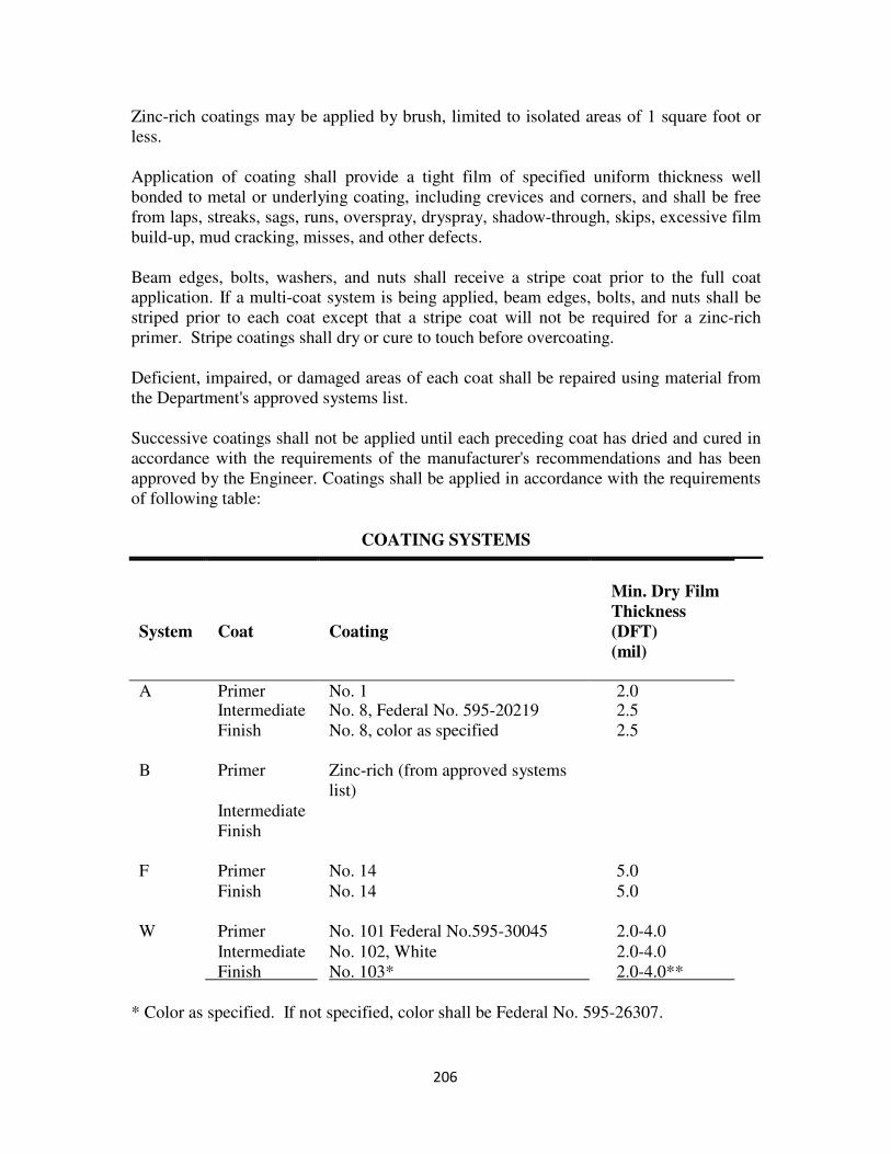
206
Zinc-rich coatings may be applied by brush, limited to isolated areas of 1 square foot or
less.
Application of coating shall provide a tight film of specified uniform thickness well
bonded to metal or underlying coating, including crevices and corners, and shall be free
from laps, streaks, sags, runs, overspray, dryspray, shadow-through, skips, excessive film
build-up, mud cracking, misses, and other defects.
Beam edges, bolts, washers, and nuts shall receive a stripe coat prior to the full coat
application. If a multi-coat system is being applied, beam edges, bolts, and nuts shall be
striped prior to each coat except that a stripe coat will not be required for a zinc-rich
primer. Stripe coatings shall dry or cure to touch before overcoating.
Deficient, impaired, or damaged areas of each coat shall be repaired using material from
the Department's approved systems list.
Successive coatings shall not be applied until each preceding coat has dried and cured in
accordance with the requirements of the manufacturer's recommendations and has been
approved by the Engineer. Coatings shall be applied in accordance with the requirements
of following table:
COATING SYSTEMS
System
Coat
Coating
Min. Dry Film
Thickness
(DFT)
(mil)
A Primer No. 1 2.0 Intermediate No. 8, Federal No. 595-20219 2.5
Finish No. 8, color as specified 2.5
B
Primer
Zinc-rich (from approved systems
list)
Intermediate
Finish
F
Primer
No. 14
5.0
Finish No. 14 5.0
W
Primer
No. 101 Federal No.595-30045
2.0-4.0
Intermediate No. 102, White 2.0-4.0
Finish No. 103* 2.0-4.0**
* Color as specified. If not specified, color shall be Federal No. 595-26307.
207
** DFT shall be no less than specified thickness; however it shall completely cover the
intermediate coat.
Quality Control
Inspector must measure the dry-film thickness of the coating with a Tooke gage when the
thickness of previous coatings is not known. When the thickness of previous coatings is
known a magnetic dry-film thickness gage is to be used. An adhesion test should be
performed.
The Contractor is responsible for repairing test areas at no additional cost.
Contractor's Record Keeping
Section 411 specifies the requirements for the Contractor to maintain daily records. The
Inspector should be familiar with the requirements specified.
Environmental Protection
Environmental Plan
The Contractor has a responsibility to protect the public and the environment from leaded
paint and hazardous material resulting from preparation operations.
If surface preparation operations are required, the Contractor is required to submit a
detailed site-specific environmental plan for review. Once the plan is approved, the
Inspector must ensure the Contractor is in compliance with the plan.
Monitoring
The Inspector must perform continuous visual inspections of containment structures, dust
collectors and abrasive recycling equipment to detect any emissions into the unconfined
space.
Perimeter air monitoring shall be performed as stated in the environmental plan. Should
emissions exceed the limits established in Section 411, the Contractor is required to
notify the Inspector immediately and operations are to be halted until corrective actions
are implemented.
Storage and Disposal of Waste Material
Section 411 contains very specific instructions for storage requirements of waste
material. The Inspector needs to be familiar with these requirements and ensure that they
are adhered to by the Contractor. The Contractor will not be permitted to store hazardous
material on Department property.
208
Health and Safety Plan
The Contractor shall prepare a worker health and safety plan. This plan is to be prepared
and approved by a Certified Industrial Hygienist currently certified by the American
Board of Industrial Hygiene or by a SSPC QP-2 Supervisor/Competent Person.
These plans shall not be submitted to the Engineer for approval, but shall be submitted
for the Engineer’s review and record. After project award but not less than three weeks
prior to commencing operations, the worker health and safety plan shall be submitted to
the Engineer.
In no case shall the Contractor be allowed to begin work prior to the Engineer’s receipt
and review of a satisfactorily complete plan.
The CIH or SSPC QP-2 Supervisor/Competent Person providing plan approval or a
qualified designated representative shall be present during start-up, surface preparation
periods and as needed during removal operations throughout the duration of the project to
ensure the provisions of the worker safety and health plans are properly implemented.
At completion of the project, the CIH or SSPC QP-2 Supervisor/Competent Person shall
submit a written statement of certification for the Engineer’s record, complete with all
revisions including notations of any areas of non-compliance and corrective actions
taken, that the worker health plans fully complied with all regulations and that the plans
were fully implemented.
Inspector's Checklist
1. Did the Contractor submit proof of the required certification prior to beginning work?
2. If a containment structure was erected, was the structure certified by a Professional
Engineer licensed in the Commonwealth of Virginia?
3. Are all surfaces prepared as specified?
4. Did the Contractor contain all solid and liquid waste during surface preparation?
5. Is the coating operation done in accordance with Section 411?
6. Are all surfaces dry prior to coating operations?
7. Has the coating material been tested and approved?
8. Is the coating applied at the specified thickness?
9. Are preceding coats dried or cured and approved by the Engineer prior to subsequent
coats being applied?

209
10. Does the Contractor maintain daily records as specified?
11. Is waste material stored and disposed of as specified?
12. Did the Contractor submit the required worker health and safety plan?
13. Did the Contractor submit the required compliance certification at the end of the
operation?
210
SECTION 412 – WIDENING, REPAIRING, AND
RECONSTRUCTING EXISTING STRUCTURES
Description
On a regular basis, bridges are repaired and reconstructed to prolong the life of the
structure and widened to meet current needs and requirements. There are various types
of repairs that can be made to the substructure and superstructure. Inspectors should
become familiar with the requirements for the various types of repairs specified in
Section 412 of the Specifications when assigned to a project in which widening,
repairing, or reconstructing existing structures are involved.
Procedures
General
Concrete structures are repaired by removing and replacing deteriorated concrete,
thoroughly cleaning concrete and reinforcing steel to remain, and replacing reinforcing
steel if necessary. Cleaning can be performed by sand blasting, water blasting or other
approved methods to remove concrete, rust, oil and other foreign materials that will
prevent achieving a bond with the new concrete. Epoxy coated reinforcing steel is not to
be cleaned by sandblasting.
Areas to be repaired should be sawcut to a depth of 1 inch. Deteriorated concrete should
be removed using hand tools or pneumatic hammers weighing 30 pounds or less.
Pneumatic hammers should be angled toward the area to be removed to prevent damage
to concrete that is to remain. Care should be taken to ensure the existing reinforcing steel
is not damaged.
When existing reinforcing steel has lost ¼ or more of its original cross section, it shall be
lapped with new bars of the same size and shape. News bars must lap the existing bars
30 times the diameter of the bars on each side of the damaged portion.
Where new concrete is to be placed against existing concrete, dowels at least ¾ inch in
diameter are to be installed at no more than 2 feet 6 inch center to center. The dowels
should be installed perpendicular to the existing concrete by drilling and grouting.
Bridge Superstructure Repairs
Type A milling consists of milling the surface of a bridge deck to a depth of ½ inch.
Equipment must be capable of removing ½ inch of concrete uniformly in one pass.
Power hand tools will be needed to work around reinforcing steel and in confined areas.

211
Type A patching consists of repairing the deck surface or milled area to a depth that will
not exposed the reinforcing steel.
Type B patching consists of repairing the deck or milled area to a depth of at least 1 inch
below the top mat of reinforcing steel.
Type C patching consists of repairing the full depth of the deck. For full depth repairs
of 3 square feet or less, forms may be suspended from the reinforcing steel. For larger
areas, blocking must be used to support the forms.
Epoxy-mortar patching is accomplished the same as Type A patching except the depth
is up to and including ¾ inch. Surfaces need to be dry and primed with neat epoxy just
prior to placing the mortar. The surface is to be sprinkled with sand before the epoxy sets
or sandblasted just prior to placement of the seal to ensure bonding.
Crack repairs are done by V-grooving structural and dormant cracks to a depth of ½
inch and blown clean. The groove is then filled with neat epoxy. If latex patches are to
be made, the Contractor may brush latex into the groove if the patches are done
monolithically.
Concrete superstructure surface repairs include repairs to raised medians, median
barriers, beams, diaphragms, parapets, posts, rails, curbs, and sidewalks. These surface
repairs are to be made with Type B patches. When the patches are 2 inches thick or
more, welded wire fabric is needed. The fabric is to be tied to the reinforcing steel if
possible. If not possible, expansion bolts are to be installed and the fabric tied to the
bolts.
Joint opening repairs and reconstruction are accomplished by removing concrete,
repairing or replacing reinforcing steel, cleaning exposed surfaces and re-casting the joint
with hydraulic cement concrete.
Bridge Deck Overlay Repairs
Prior to placing a bridge deck overlay all deck repair concrete must attain at least 93
percent of the minimum designed compressive strength.
The Inspector is to ensure that existing expansion joints and dams are maintained through
the overlay. This is accomplished by installing a bulkhead the same width as the existing
joint and installed to the proposed grade and profile.
If major delays occur during placement of the overlay, a construction dam or bulkhead is
to be installed. For delays of 1 hour or less, the Inspector must ensure that the end of the
placement is protected from drying.
212
Latex or Silica Fume Overlay
Within 24 hours immediately prior to placing the overlay, the entire deck surface is to be
thoroughly cleaned. The edge of the previously placed adjacent overlay shall also be
cleaned.
For at least 1 hour prior to placing the overlay, the deck is to be soaked with water. An
effective method is to cover the soaked deck with plastic to hold in the moisture.
Standing water must be removed prior to placing the overlay.
Overlays are to be placed only when the temperature is 50 degrees F and rising. If the
temperature is above 85 degrees F, the Engineer may require the overlay to be placed at
night or in the early morning hours.
Mixers for latex hydraulic cement concrete are either batch mixers or automatic mobile
continuous mixers. They must conform to the requirements of Section 217 of the
Specifications. The Contractor shall perform yield tests on these mixers prior to
placement of the overlay. Mixers for silica fume concrete shall be truck mixers that
conform to Section 217.
The thickness of the overlay shall be at least 1 ¼ inch. The Contractor may use the
overlay for Type A, B, or C patches or joint and crack repairs, if these repairs are placed
monolithically with the overlay.
Prior to placing the overlay, the latex or silica fume concrete is to be brushed over the
surface of the existing deck. The paste from the latex or silica fume acts as a bonding
agent. The Inspector should ensure that the deck and adjacent vertical surfaces are
coated. This coating must be applied directly ahead of the overlay placement to ensure
that the coating does not become dry prior to the overlay placement. Excess aggregate
from the coating operation must be removed prior to placement of the overlay.
The evaporation rate of surface moisture must be strictly controlled to prevent surface
cracking. If the evaporation rate exceeds 0.05 pounds per square foot per hour, measures
need to be taken to control the evaporation rate. One effective method is to increase the
relative humidity at the surface by fogging.
The surface of latex and silica fume overlays must be protected from drying or cracking
by placing wet burlap on the overlay. This needs to be accomplished immediately
following screeding of the overlay.
Latex and silica fume overlays are to be measured and paid for by the square yard for the
thickness specified in the contract documents.
213
Bridge Substructure Repairs Concrete substructure surface repairs are made using Type B patching along with welded
wire fabric. Prior to jacking and blocking beams, the Contractor must submit his method
of jacking and blocking to the Area Construction Engineer for approval. Unless
approved in writing by the Engineer, structures supported on jacks will not be subjected
to traffic loadings.
Shotcrete When shotcrete is used, repairs shall be done in accordance with the requirements of
Concrete Superstructure Surface Repairs and Bridge Substructure Repairs.
Two classes of Shotcrete are as follows:
Class A - Class A shotcrete shall contain a minimum of 658 pounds of
cementitious material per cubic yard. Class A shotcrete shall have a minimum
compressive strength of 5000 pounds per square inch at 28 days. Class A
Shotcrete is reinforced with either steel or synthetic fibers. When steel fibers are
used, the minimum fiber content shall be 60 pounds per cubic yard. When
synthetic fibers are used, the minimum fiber content shall be 6 3/4 pounds per
cubic yard. The minimum thickness of Class A shotcrete cover over reinforcing
steel shall be 2 inches except in transition areas where shotcrete is feathered to
existing concrete with less than 2 inches of cover or where patches are made on
existing concrete with less than 2 inches of cover over reinforcing steel.
Class B - Class B Shotcrete shall contain a minimum of 635 pounds of
cementitious material per cubic yard. Class B shotcrete shall have a minimum
compressive strength of 4000 pounds per square inch at 28 days. The minimum
thickness of Class B shotcrete cover over reinforcing steel shall be 2 inches
except in transition areas where shotcrete is feathered to existing concrete with
less than 2 inches of cover or where patches are made on existing concrete with
less than 2 inches of cover over reinforcing steel. Where shotcrete containing
silica fume is used, the minimum cover over reinforcing steel shall be 1½ inches.
The Inspector should verify that the Contractor has an approved mix design and
performance test data with the Engineer's approval on file.
Wet Process: Shotcrete subject to freezing and thawing shall contain an air content of 7.0
percent ± 1.5 percent as delivered to the job site. The materials for wet process shotcrete
shall be mixed in accordance with the requirements of Section 217 and applied within 90
minutes after batching.
Dry Process: Solid ingredients for dry-mix shotcrete shall be predampened as needed and
mixed in a batch type or continuous mixer. Most of the mixing water shall be added at the
214
nozzle. Dry-mix shotcrete material shall be applied within 45 minutes after batching or pre-
dampening.
Equipment and Personnel
Prior to starting the work, the Inspector must verify that equipment used to deliver shotcrete
has been approved for use by the Engineer. The equipment shall be capable of discharging
the shotcrete mixture in a continuously smooth stream of uniformly mixed ingredients. Air
added at the nozzle shall be free from oil or other contaminants, and the air pressure shall be
capable of maintaining sufficient nozzle velocity to all parts of the work.
Prior to starting the work, the Inspector is to verify that the nozzleman and supervisors are
qualified as stated in Section 412 of the Specifications.
Surface Preparation
The Inspector should ensure that the perimeter of all areas where concrete is removed
shall be tapered at approximately a 45-degree angle, except that the outer edges of all
areas removed by chipping shall be sawcut perpendicular to the surface to a minimum
depth of 1/2 inch to prevent featheredging unless otherwise approved by the Engineer.
Earth surfaces shall be trimmed to line and grade and shall have adequate support to prevent
displacement during shotcrete placement. Shotcrete shall not be placed on an earth surface
that is frozen, spongy, or subject to free running water at the time of the application of
shotcrete. Active seeps, drips, and flowing water shall be controlled by installation of
suitable drain systems such that water pressure does not build behind shotcrete linings.
Excessive loss of mixing water from the Shotcrete must be prevented. This shall be
accomplished by one of the following procedures:
1. Wet the soil prior to the time of gunning to the extent that it is damp but with no
visible free water on the surface. Puddling, ponding, or freestanding water shall be
eliminated from areas to be shotcreted.
2. As an alternative or when specified, install a moisture barrier system to inhibit the
movement of moisture from the newly placed shotcrete into the earth. Wrinkling
and folding of moisture barrier will not be permitted.
Rock surfaces shall be free of loose material, debris, chips, mud, dirt, and other foreign
matter. The Inspector should verify that surfaces are damp at the time of gunning, and there
is no puddling, ponding, or freestanding water.
Wood forms which are to be removed after use shall have a form release agent applied to
prevent the absorption of moisture and inhibit the bond between shotcrete and the form.
215
Application
Shotcrete shall have a temperature of at least 50 degrees F but not more than 85 degrees F
during application. The ambient and surface temperature shall be 50 degrees F and rising.
At ambient air temperatures above 85 degrees F the Engineer may require placement to be
made at night or during early morning hours.
Shotcrete to be applied to uneven and previously repaired surfaces shall first be applied to
any deep hole, deeply excavated sections, corners, or areas where rebound cannot escape or
be blown free. The thickness of the shotcrete layer shall be such that no sloughing, sagging,
tearing, or debonding will occur. Existing concrete shall be sandblasted within 24 hours of
application and the surface shall be damp just prior to application.
Where a layer of shotcrete is to be covered by a succeeding layer, it shall be first allowed to
develop its initial set. Then all loose, uneven, or excess material, glaze, and rebound shall
be removed by brooming, scraping, or other means. Any surface deposits that take a final
set shall be removed by sandblasting, and the surface cleaned with an air-water blast from
the nozzle. Curing compounds shall not be applied to surfaces that will be covered by an
additional layer of shotcrete.
Shooting wires, ground wires, or other devices acceptable to the Engineer shall be used to
control the line, grade, and thickness of the shotcrete.
During the shotcrete application, the nozzle shall be held perpendicular to, and when
possible, 3 to 5 feet away from the receiving surface and rotated steadily in series of small
oval or circular patterns. Whenever possible, sections shall be gunned in one layer to the
full design thickness. However, for multiple layers of reinforcement, gunning of one layer
of shotcrete may be required for each layer of reinforcement.
When encasing reinforcement, the nozzle shall be held closer than normal and at a slight
upward angle. The mixture may be wetter than normal, but not so wet that sloughing behind
the reinforcement will occur.
Vertical surfaces shall be gunned starting at the bottom. Rebound or previously expended
material shall not be incorporated in the applied layer, and all such material shall be
removed from the surface and work area prior to final set and before placement of shotcrete
on adjacent surfaces. Shotcrete shall not be placed if drying or stiffening of the mixture is
occurring.
Finishing
Prior to the initial set, the shotcrete surface shall be scraped or cut with a trowel or metal
template to obtain an even and aesthetically acceptable appearance. The final finishing shall
be with a wet sponge unless otherwise specified. Trowel or float smoothing will not be
allowed.
216
Curing
After gunning, the surfaces of shotcrete shall be protected from drying or cracking. When
necessary, fogging shall be used prior to the application of moist curing or a curing
compound. Shotcrete shall be moist cured for a period of at least 7 days or cured using a
curing compound conforming to the requirements of Section 220. The rate of application
shall be not less than 1 gallon of curing compound per 100 square feet of surface. The color
of the curing compound shall be approximately that of the existing concrete.
Quality Assurance and Testing
Preconstruction testing may be waived by the Engineer if it can be shown that the crew to be
used is qualified and that the mixture has been successfully used in similar work.
Test panels 24 inches by 24 inches by 4 inches deep containing steel reinforcement
representative of that to be used on the project shall be prepared. Each crew shall gun two
test panels with the mix design to be used on the project and for each gunning orientation to
be encountered on the job. Panels will be cured in the field in the same manner as the
structure for 1 day and transported to the laboratory, where curing shall be continued until
time of testing. For shotcrete jobs of less than 200 square feet, the Contractor shall cut one
of the test panels with a trowel or a metal template before the initial set, in the presence of
the Engineer, to check visually for possible voids under the reinforcement. For larger jobs
where specific evidence of good encasement of reinforcing bars is needed, the Contractor
shall cut cores from the test panels after the concrete has hardened for at least 3 days. Cores
shall be cut through the steel.
The second panels for all jobs shall be used to determine the compressive strength of the
applied shotcrete. Cores shall be 2 inches to 4 inches in diameter and shall be taken
between the reinforcement and tested by the Department at the specified age in accordance
with the requirements of ASTM C42.
In-place shotcrete shall be of uniform quality and free from segregation, honeycombing,
sand pockets, sand lenses, sagging, dry patches, overspray, rebound, or incomplete
encasement of reinforcement. It shall also be free from delamination, cracking, or single
voids with dimensions in excess of 1/4 inch.
The Contractor shall remove and replace or correct defective shotcrete to the satisfaction of
the Engineer.
For compressive strength tests, one test panel shall be prepared for each day’s production or
for each 200 square feet of shotcreting by each crew using the same ingredients and gunning
orientation as the shotcrete applied to the job. These panels shall be cured and delivered to
the designated testing laboratory as earlier specified in this section.
217
Inspector's Checklist
1. Is cleaning performed by sandblasting, waterblasting, or other approved methods in
order to remove concrete or other materials detrimental to achieving a bond?
2. Are areas to be repaired outlined with saw cuts to a depth of at least 1 inch or that
which will clear the top of reinforcing steel?
3. Is all the loose and unsound material removed using hand tools or pneumatic
hammers weighing 30 pounds or less and worked at an angle of 45 to 60 degrees to
the plane of the concrete surface being removed?
4. Is exposed reinforcing bars being cleaned, with sandblasting not done on epoxy
coated steel?
5. Are reinforcing bars that have lost 1/4 or more of their original cross-sectional area
repaired in accordance with this section?
6. Is dust and debris removed by blowing with compressed air or by hosing with water?
7. Are dowels or expansion bolts provided when joining new and existing concrete?
8. Is superstructure surface repair performed in accordance with Type B patching?
9. When concrete surface repairs are made, is a cover of at least 2 inches maintained
over all reinforcing steel, expansion bolts, and welded wire fabric, except in transition
areas, at patches less than 2" in depth over existing concrete?
10. Has the deck repair concrete attained 93% of the minimum design compressive
strength before overlays are placed?
11. Is vehicular traffic not allowed on the bridge until the overlay obtains a compressive
strength of 3,500 psi?
12. Is the end of the overlay placement protected from drying during delays of 1 hour or
less?
13. Within 24 hours immediately preceding the beginning of latex or silica fume concrete
overlay, is the entire surface to be overlaid thoroughly cleaned?
14. Is the surface to be overlaid continuously and thoroughly water soaked for at least 1
hour prior to overlay placement?
15. Is overlay placed only when the ambient air temperature is 50 degrees F and rising?
218
16. Is a thorough, even coating of latex concrete or silica fume brushed onto the prepared
surface prior to overlay placement?
17. Are measures taken to reduce the rate of evaporation if the rate exceeds 0.05 lb/sq
ft/hr during placement?
18. Is the latex concrete surface cured through prompt application of wet burlap, covered
with polyethylene, and kept continuously moist for the initial 48 hour curing period,
followed by 48 hours of air curing?
19. Is concrete removed to a depth as specified on the plans or as directed by the
Engineer?
20. Did the Contractor submit a method of jacking and blocking beams for seat repair for
the Engineer's approval?
21. Was written approval obtained from the Engineer prior to subjecting structures
supported on jacks to traffic loadings?
22. Is the minimum thickness of Class A, Class B, or shotcrete containing silica fume as
specified for cover over reinforcing steel?
23. Is shotcrete delivery equipment approved by the Engineer prior to commencement of
the work?
24. Is gunning of test panels required for approval of inexperienced nozzlemen or
supervisors?
25. Do temperature requirements and application methods conform to the requirements of
this section?
26. Is initial and final finishing performed as specified?
27. Are test panels for compressive strength and for preconstruction testing, if required,
prepared as specified?
28. Have sufficient measurements been taken and recorded to facilitate payment for the
repair performed?
219
SECTION 414 - RIPRAP
General
Since channel changes usually alter the hydraulic characteristics of a stream, riprap is
frequently specified to protect property and roadways from erosion. When riprap is
specified, the type and location will be specified on the plans.
The Project Inspector is to visually examine the slope upon which the plans designate
riprap is to be placed. If the slope material appears coarser than the bedding aggregate
specified, then the Project Inspector is to contact the District Materials Engineer, through
normal channels, for a more detailed investigation to determine the actual need for the
bedding. If the slope is comprised of solid rock or closely consolidated boulders whose
soundness, size, and weight equal or exceed the Specifications for the proposed riprap,
then the riprap may be deleted by the District Materials Engineer.
The Materials Division or the hydraulic section of the Location and Design Division will
be available to assist in establishing the need and proper field location for riprap. The
plans show the general location but the definite limits must be determined based on field
inspections.
Eddy currents often develop at the terminal ends of riprap. These terminals should be
tied into some existing undisturbed features such as a boulder or rock outcrop. The
alignment of riprap should conform as nearly as possible to the existing alignment of the
stream. Any sharp change in alignment causes changes in the characteristic flow of the
stream and can increase the rate of erosion at some point along the stream or river.
The following table may be used as a guide to approximate certain rock dimensions to
equivalent weights. This table is not to be used for acceptance or rejection of riprap
material.
Weight Height Mean Spherical
Diameter
Rectangular
Shape Length
50 lbs. 0.5' 0.8' 1.4'
100 lbs. 0.6' 1.1' 1.75'
150 lbs. 0.67' 1.3' 2.0'
300 lbs. 0.9' 1.6' 2.6'
500 lbs. 1.0' 1.9' 3.0'
1000 lbs. 1.25' 2.2' 3.7'
1500 lbs. 1.5' 2.6' 4.7'
2000 lbs. 1.8' 2.75' 5.4'
2 tons 2.0' 3.6' 6.0'
3 tons 2.3' 4.0' 6.9'
4 tons 2.5' 4.5' 7.6'
10 tons 3.3' 6.1' 10.0'
220
It is essential for Project Inspectors to ensure that Contractors furnish and place the class
of dry riprap specified on the plans. To avoid project delays and minimize material
rejections the following procedures have been developed with the producers.
The classes of dry riprap shall be as follows:
1. Class I: Stones shall weigh between 50 and 150 pounds each. At least 60
percent shall weigh more than 100 pounds, and approximately 10 percent may
weigh 50 pounds or less.
2. Class II: Stones shall weigh between 150 pounds to 500 pounds each. At least
50 percent shall weigh more than 300 pounds, and approximately 10 percent
may weigh 150 pounds or less.
3. Class III: Stones shall weigh from 500 pounds to 1,500 pounds each. At least
50 percent shall weigh more than 900 pounds, and approximately 10 percent
may weigh less than 500 pounds.
4. Class AI: Stones shall weigh between 25 and 75 pounds each, except that
approximately 10 percent may weigh 25 pounds or less and 10 percent may
weigh 75 to 100 pounds.
Stockpiled Dry Riprap
The Inspector is to verify the size and acceptability of the material at the quarry prior to
shipment.
Dry Riprap to be shipped as it is produced
The Inspector is to establish by visual inspection with the Contractor and the producer the
size and percentages required to meet the Department’s Specifications.
The Contractor should furnish a sample of the minimum to maximum size riprap at the
project work site to be used for visual comparison of riprap delivered to the project and a
sample should be maintained at the quarry for the producers benefit. When necessary,
the Inspector may request assistance from the District Material Engineer to visit the
quarry and establish the size and percentages of dry riprap.
221
Procedures
Grading: The Inspector should verify that the slope to receive the riprap has been graded to
within 6 inches of the lines shown on the plans. Riprap or bedding shall not be placed until
the prepared base has been approved by the Inspector.
Bedding: Riprap bedding is placed on the embankment to form a backing for riprap.
Bedding shall be spread uniformly on the prepared base. Compaction of the bedding
material will not be required, but material shall be finished to a reasonably even surface, free
from mounds or depressions.
When geotextile bedding material is required, the entire perimeter of the material shall be
turned down and buried at least 9 inches for anchorage. Adjacent strips of material shall run
only up and down the slope and shall overlap at least 18 inches. Geotextile bedding material
shall not be used on slopes greater than 1:1. Damaged material shall be replaced or repaired
with a patch of the same material overlapping the damaged area by at least 18 inches on all
sides. Material shall be placed loosely so that positioning riprap will not stretch or tear it.
Placing stones: Riprap shall be placed on the embankment as soon as practicable after
bedding has been finished, but no later than 15 days.
Riprap shall be placed to its full course thickness in one operation and in a manner to avoid
displacing underlying material. Riprap stone shall not be dropped onto fabric from a height
greater than 1 foot. Smaller-sized material shall not be dropped onto fabric from a height
greater than 3 feet. Larger stones shall be reasonably well distributed. Hand placing may be
required to the extent necessary to secure the results specified and form uniform slopes.
A tolerance of ±1/4 of the thickness of the maximum-size stone from the lines and grades
shown on the plans will be allowed in the finished surface.
Placing riprap by dumping into chutes or similar methods likely to cause segregation of the
various sizes will not be permitted.
Mortared Riprap
Stone shall be the same size as specified for dry riprap, Class II, and shall be selected to
secure fairly large, flat-surfaced stones that will produce a true and even surface with a
minimum of voids.
Stones shall be placed first and roughly arranged in close contact, with the larger stones
placed near the base of the slope. Spaces between larger stones shall be filled with stones of
suitable size, leaving the surface reasonably smooth and tight and conforming to the contour
required.
222
As each larger stone is placed, it shall be surrounded by fresh mortar, and adjacent stones
shall be shoved into contact. After larger stones are in place, spaces or openings between
them shall be filled with mortar, and smaller stones shall then be placed by shoving them
into position, forcing excess mortar to the surface, ensuring that each stone is carefully and
firmly bedded laterally.
Grouted Riprap
Grout shall consist of 1 part hydraulic cement and 3 parts sand, thoroughly mixed with
water to produce grout having a thick, creamy consistency.
Stones shall be of the same sizes and placed in the same manner as specified for dry riprap,
Class I. Care shall be taken during placing to keep earth or sand from filling spaces between
stones. After stones are in place, spaces between them shall be filled with grout from
bottom to top and the surface swept with a stiff broom. Riprap shall not be grouted in
freezing weather. In hot, dry weather, the work shall be protected from sunlight and kept
moist for at least 3 days after grouting by the use of saturated burlap.
Inspector's Checklist
1. Is all vegetation removed from the slope prior to placement of the riprap?
2. Is the slope graded as required?
3. Is geotextile fabric installed properly if required?
4. Is riprap of the gradation specified?
5. Is riprap keyed into existing toe of fill or stream bed as shown on plans or as directed
by the Engineer?
223
SECTION 415 – CONCRETE SLOPE PROTECTION
General
The plans may require concrete slope protection to be constructed with pre-cast blocks or
"cast-in-place" concrete slabs. When blocks are required, the joints between the blocks
are filled with mortar. In the case of cast-in-place slabs, all joints are ordinary
construction butt joints. Horizontal joints to be continuous on the face of the slope with
vertical joints being staggered perpendicular to the horizontal joint.
Slope protection requires the firm support of bedding material, although it has the
structural strength to "bridge over" small local voids. Adequate drains must be provided
to prevent an uplift force from frost action and from the pressure of water trapped behind
the slope.
A 2 inch bedding of Grade B sand may be specified as bedding material beneath the slope
protection. Weep holes may be formed in the concrete to provide drainage.
Cast-in-place slope protection is used more often than the block type. All slabs are
reinforced and tied together with woven wire fabric. If the slabs are to have the
necessary rigidity and durability, the wire fabric must be positioned at mid depth of the
slab. Frequently, the weight of the fresh concrete pushes the wire below mid depth and
the workers neglect to reposition it accurately. Considerable attention must be given to
this very important detail.
The Contractor may elect to place slope protection in alternate horizontal or vertical
strips and score the perpendicular joints with a jointing tool in lieu of placing the concrete
in alternate blocks.
If the slope protection is for a roadway grade separation rather than a bridge over a
stream, examine the grading plans for ditch line elevations. The ditch line elevations on
the roadway plans should agree with those of the slope protection on the bridge plans.
Any differences are to be brought to the attention of the Construction Manager.
Finally, check the layout of slope protection in the field. All slope protection is to extend
along the slope for a sufficient distance to catch storm water dripping from the outer
edges of the deck. A slight amount of additional concrete here will eliminate a serious
erosion (maintenance) problem.
Method of Measurement
The actual field dimensions (measured to the nearest tenth of a linear foot), pertinent
calculations and detailed sketches necessary to determine the actual area of the slope
protection (rounded to the nearest square yard per abutment), are to be recorded in the
224
project records. If an individual protruding fixture has an area greater than 9 square feet,
that area is to be deducted from the total area of the slope protection.
Inspector’s Checklist
1. Is the subgrade constructed properly?
2. Is the 2 inch bedding material placed properly?
3. Are blocks laid with continuous horizontal joints and staggered joints extending up
and down the slope?
4. Are all joints filled with mortar?
5. Is cast in place edging placed as specified?
6. Is the toe of slope protection in alignment with proposed and/or existing ditch?
225
SECTION 419 - BRIDGE CONDUIT SYSTEMS AND
LIGHTING SYSTEMS
Description As soon as practicable, the Inspector should carefully study the plans, Specifications and
Special Provisions and become familiar with the requirements therein. Layouts should be
checked to determine any omissions or necessary changes.
Materials Electrical materials are to conform to Section 238 and must be approved for use by test
report or certification prior to payment. Occasionally, plans will specify a manufacturer's
brand name, model number, and state "or equal." If the Contractor elects to order an
"equal," he is to submit pertinent details (drawings and manufacturer's specifications) to
the Area Construction Engineer for review and approval prior to ordering such materials.
Installation Installation is to be performed in accordance with Section 700. Conduit is generally
installed in conjunction with the reinforcing steel and is to be placed so as not to interfere
with the proper location of the steel. Conduit should be secured in place to avoid
dislocation or damage which would affect installation of wiring.
Conduit that has been crushed, kinked, or in any way deformed is not to be used in the
work. During installation, conduit is to be kept free of dirt or other objectionable
material. After installation, there should be no obstructions in the conduit that will hinder
the "pulling" of electrical conductors.
The location of the conduit "runs" shown on the plans is for the purpose of circuitry and
bidding only. During construction it may be advantageous to alter or change the runs
somewhat to avoid obstacles unforeseen during design stages.
Conduit field cuts are to be made with a pipe cutter with the ends square. When metal
conduit is properly joined, the ends are butted tightly together. Periodically, the Inspector
should test the couplings with a wrench to see that the joints are made up tight.
Field cuts in non-metallic conduit are also to be made square. Couplings should be
checked to ensure that the proper gaskets are installed correctly and that the joint is tight.
Conduit is to be equipped with expansion and deflection fittings which coincide with
bridge joints. Sufficient slack is to be left in conductors to allow for movement of bridge
sections. When a bonded system is required, care should be exercised to ensure
continuity of the system by flexible bond across moveable fittings. Where non-metallic
226
conduit is used, the system is bonded internally with a bare copper wire no smaller than
No. 6.
Inspector's Checklist
1. Are materials tested and certified as specified?
2. Did the Contractor notify the Engineer at least 48 hours prior to energizing the
electrical system?
3. Are all required conduits, expansion and deflection fittings and electrical items
installed as specified?
4. Are all joints made up tight?
5. Are all conduit runs clear of obstructions after installation?

227
INCIDENTAL CONSTRUCTION
228
SECTION 501 – UNDERDRAINS
Description
The locations of underdrains are usually determined by soils investigations prior to
completion of the plans or during grading operations. Underdrains are placed to lower
the water table or to intercept and dispose of water seeping into the roadway from
backslopes or other sources outside of the roadbed. Changes in design location,
elimination of underdrains, or the selection of additional locations should be made by the
Area Construction Engineer or District Materials representative and documented in the
project diary.
Installation Underdrains should be placed with their perforations down or as directed by the
Engineer. Non perforated pipe should be used for outlets or crossdrains. Non perforated
pipe need not be backfilled with granular material. Blind drains are often installed, in
which case the pipe is omitted, and the water is lowered by the use of free draining
material.
Inspectors should verify that geotextile drainage fabric is installed and lapped properly.
The designated area shall be cleared of debris prior to fabric installation. Large holes shall
be filled with sandy, coarse material, and sharp contours and rises shall be leveled. Adjacent
strips of geotextile drainage fabric shall be overlapped at least 12 inches. If fabric is torn or
punctured, it shall be repaired with the same type of fabric.
Inspectors should also verify that the correct type of aggregate is placed as shown in
Section 108 of the Road and Bridge Standards.
Semi-round underdrain pipe is to be installed with the rounded section down. Wherever
the depth of trench is modified for any reason to a depth less than normally specified,
ABS or PVC pipe is not to be allowed.
For underdrain outlets non-perforated pipe shall be placed in the trench with sections
securely joined. After pipe installation has been approved by the Engineer, the trench shall
be backfilled with aggregate material in layers not more than 6 inches in depth and
thoroughly compacted.
Installation of EW-12 Endwalls and outlet markers shall be in accordance with Section 101
of the Road and Bridge Standards.
Method of Measurement Underdrains of all types are to be measured to the nearest linear foot for each line.
229
Inspector’s Checklist
1. Are all cuts checked for springs and seepage after heavy rains?
2. Are trenches excavated to the proper depth and width?
3. Is non-perforated pipe used for outlets?
4. Are the upgrade ends of pipes adequately capped or plugged?
5. Are pipe joints checked to ensure tight connections?
6. Is the pipe placed and bedded in accordance with applicable Specifications and
Standards?
7. Are all special problems pertaining to drainage brought to the attention of the Area
Construction Engineer?
8. Is an adequate number of outlets provided for all underdrains? Are outlets so located
that there is no chance of water backing into underdrains during heavy storms?
9. Are all pipe outlets checked to ensure they had not been crushed or displaced during
construction?
10. Are all outlets checked after periods of heavy rainfall to ensure that they were flowing
freely.
11. Did the Contractor place markers at outlet end of all underdrain installations?
12. Is extra depth installation over 4 feet adjusted for pay in accordance with Section
501?
230
SECTION 502 – INCIDENTAL CONCRETE ITEMS
General Incidental concrete items include paved ditches, paved flumes, curbs, gutters,
combination curbs and gutters, bridge drainage aprons, concrete median barriers, median
strips, sign islands and directional island curbs.
These items are shown on the plans by the designer in locations and in quantities based
on the field data he has available. Additions or deletions may be necessary to suit
conditions on the project. As soon as practical, the Project Inspector should review the
project with the Area Construction Engineer for any necessary changes.
Procedures Areas should be excavated to the proper grade and thoroughly compacted.
All forms must be straight, free from warp and be of sufficient construction to allow for
concrete placement without shifting. Forms should also be free of foreign matter and
oiled prior to placement of concrete. If the forms do not meet the requirements of the
Specifications, they should be rejected by the Inspector, and the Contractor should be
required to provide forms that are acceptable. It is suggested that a small mark be placed
on forms that do not meet Specification requirements to assist in identifying unacceptable
forms.
Inspectors should verify that forms are set to the correct grade and check the horizontal
and vertical alignment prior to placement of concrete. The alignment of all forms is to be
smooth and pleasing to the eye. The longer the form line the easier it is to detect and
remove minor irregularities. The value of "eyeballing" to detect obvious mistakes and
minor irregularities cannot be overemphasized.
The foundation material must be uniformly compacted and shaped to the correct
elevation. The gravel or crushed stone particles that collect along the inside edges of the
forms are to be removed. The presence of this loose material may lead someone to
incorrectly conclude that the concrete lacks proper depth (when they observe the sides of
the concrete section after removal of the forms). The Inspector should ensure the
subgrade is thoroughly moistened prior to placement of concrete.
The Contractor should straightedge the flow line of gutters and paved ditches while the
concrete is still workable, and remove any sags or knots that would prohibit the proper
drainage or appear unsightly. Concrete placed adjacent to forms is to be vibrated or hand
spaded to eliminate honeycomb.
The completed curb should be backfilled as soon as practical after construction. Storm
water should not be allowed to accumulate behind the curb, as it may saturate the
231
pavement structure. Care should be taken to ensure compaction of the backfill does not
cause damage to the concrete.
The Contractor may request to use slip-form equipment for placing incidental concrete
items. Approval to slip-form is contingent upon the quality, shape, and alignment of the
test section produced.
Inspectors should verify that transverse joints for crack control are provided at the
following locations:
1. at approximately 20 foot intervals
2. at the gutter where the curb and gutter tie to the gutter apron of drop inlets
3. when time elapsing between consecutive concrete placement exceeds 45
minutes
4. where no section shall be less than 6 feet in length
Crack control joints may be formed by using one of the following methods:
1. removable 1/8 inch thick templates
2. scoring or sawing to a depth not less than ¾” inch when using a curbing
machine
3. approved “leave in” type inserts
Expansion joints shall be formed at approximately 100 foot intervals, at all radii points at
concrete entrances and curb returns and at locations no less than 6 feet and no more than
10 feet from drop inlets.
Edges of concrete shall be rounded to a ¼ inch radius. Exposed surfaces immediately
adjacent to the roadway are to be given a light broom finish. Concrete median barriers
are to be given a Class I finish. Paved ditches and flumes are to be given a course or
roughened finish.
The proper curing of concrete requires the proper control of four major factors:
Humidity, temperature, wind and protection against disturbance. The concrete is to be
cured under conditions of humidity, temperature, and wind that will produce a uniform
hydration of the cement. Concrete may be satisfactorily cured by either a moisture
application system or by the uniform application of an acceptable curing compound
membrane. Do not permit the use of curing compound if an overlay will be required for
additional surfacing.
232
The Contractor is to make every reasonable effort to protect the concrete from rain or
rapid drying conditions. The concrete surface is not to be walked upon or disturbed for a
minimum of 24 hours. When open-flame heaters are used in the vicinity of combustible
concrete formwork, a watchman is to be provided by the Contractor.
Asphalt Concrete curbs shall be placed on a dry, clean surface. Immediately prior to
placement of the curb, a tack coat shall be applied at a rate of 0.05 to 0.15 gallon per
square yard. Asphalt Concrete curbs should be placed by a self-propelled automatic curb
machine, except that short section or radii may be placed by other methods with approval
of the Engineer.
Asphalt Concrete paved ditches shall be placed and compacted so as to provide a smooth,
uniform, and dense texture.
Concrete median barrier shall be constructed with a tolerance of 1/2" inch for overall
depth and width, ¼ inch for width of the upper portion, and ¼ inch per 10 feet for
horizontal alignment.
Concrete median barriers should be backfilled and compacted in 6 inch layers to required
elevation. The barrier should be backfilled as soon as the concrete curing time has
elapsed.
Inspector’s Checklist
1. Is the foundation compacted to the proper density?
2. Are the dimensions correct in accordance with the plans or applicable standard?
3. Are forms free of warp and braced to prevent movement or deflection during concrete
placement?
4. Are forms placed in the proper location and to the correct grade?
5. Are the front and back slopes of paved ditches checked?
6. Is loose material removed from within the forms?
7. Is the proper size re-bar installed?
8. Does the re-bar have the required clearance from the forms?
9. Is the concrete vibrated during placement?
10. Are edges rounded to a ¼ inch radius?
11. Are transverse crack control joints provided at the correct locations?
233
12. Are the joints formed to the correct depth using an approved method?
13. Are expansion joints placed in the correct location?
14. Are exposed surfaces given the appropriate finish?
15. Are there irregularities that would hinder the drainage flow?
16. Are sections of concrete the minimum required length?
17. Is the concrete cured and protected properly?
18. Is integral curb placed with 45 minutes of slab placement?
19. Are curb, gutter, and combination curb and gutter backfilled and properly compacted
within 3 to 7 days?
20. Is 0.05 to 0.15 gallons per square yard of tack applied to the surface prior to
placement of asphalt concrete curb?
21. Are concrete median barrier dimensions verified?
22. Is concrete median barrier properly backfilled and compacted?
234
SECTION 503 – RIGHT-OF-WAY MONUMENTS
General
Right-of-way monuments are to be set accurately in accordance with instructions in the
Road and Bridge Standards and should be checked by the Inspector to ensure the location
is as called for on the plans. The Right-of-way monuments should be thoroughly
compacted in such a manner as to not displace the monument. When the plan location of
a monument falls within an entrance or yard where its presence would be unsightly or
create a hazard, they may be set with the top flush with the ground. Where monuments
are set flush with the ground the Inspector is to reference their location (except at P.C.'s
and P.T.'s). This information is to be forwarded through normal channels to the Right-of-
Way Division in the Central Office.
Right-of-way monuments shall conform to the requirements of Section 219 of the
Specifications and shall be installed in accordance with Section 503 of the Road and Bridge
Standards.
Method of Measurement
Right-of way monuments are to be measured in units of each, complete-in-place, and
paid for at the contract unit price per each. Payment is to include excavating, backfilling
and compacting.
235
SECTION 504 – SIDEWALKS, STEPS AND
HANDRAILS
Sidewalks Sidewalks can be constructed with either hydraulic cement concrete or asphalt concrete.
The location of sidewalks should be verified by the Inspector prior to excavation. After
excavation, unsuitable material should be removed and the foundation graded to the
proper elevation and thoroughly compacted.
Forms should be free of warp and free of foreign material. Forms must be sufficiently
braced to prevent deflection or movement during placement of concrete.
When hydraulic cement concrete is used, the foundation should be thoroughly moistened
and the forms oiled prior to placement of concrete.
Class A3 concrete should be used for the construction of sidewalks. Outside edges and
joints should have a radius of ¼-inch.
Sidewalks should be finished using a hand float and light trowel marks removed with a
light brooming.
Transverse expansion joints are to be constructed at approximately 100 - foot intervals.
Slabs should be at least 3 feet in length and be separated by preformed joint filler
extending from the bottom of the slab to ¼ inch below the top of the slab.
The slab between expansion joints should be divided into 5 foot sections and separated by
transverse control joints formed by tooling. When obstructions, except for drop inlets,
penetrate the sidewalk, construction joints should be formed around those obstructions.
These joints are to be constructed using ¼ inch preformed joint material.
Where sidewalks are adjacent to curb, the expansion joints in the sidewalk and curb
should coincide.
Sidewalks should not be open to pedestrian traffic for 5 days and not open to vehicular
traffic for 14 days or until the minimum design strength had been achieved.
When liquid membrane curing compound is used, heavy concentrations should not be
allowed.
When asphalt concrete is used, a 4 inch layer of No. 8 aggregate bedding shall be placed
and thoroughly compacted. Asphalt concrete may be placed in one or more layers,
dependant on the depth required. Asphalt concrete should be accomplished using a hand
operated or power roller of sufficient weight to achieve the necessary density. Hand
tamping is only permitted in areas inaccessible to the roller.
236
Hydraulic cement concrete sidewalks should be measured and paid for by the square yard
for the depth indicated in the contract. Obstructions within the limits of the sidewalk that
is greater than 1 S.Y. shall be deducted from the measurement.
Asphalt concrete sidewalk is to be paid by the ton of asphalt material. Bedding material
is to be paid for by the ton or cubic yard at the contract unit price.
Steps
Hydraulic cement concrete steps are to be constructed in accordance with the plans or
Section 601 of the Road and Bridge Standards.
A light broom finish should be given to the tread portion of the steps.
Inspectors should pay special attention to the placement of reinforcing steel to ensure the
correct size bars are being used and the proper bends have been made.
Hydraulic cement concrete steps should be measured in cubic yards of concrete and
pounds of reinforcing steel used.
To determine the necessity for handrails, refer to Section 601.01 of the Road and Bridge
Standards.
Handrails
Handrails are constructed using standard weight pipe for rails and extra strong pipe for
posts. All metal rails, posts, and fittings shall be galvanized.
Handrail may be constructed using standard fittings or by welding. If joints are welded,
all exposed joints shall be finished smooth by grinding or filing.
Handrails are to be constructed in accordance with Section 605 and 601 of the Road and
Bridge Standards.
Handrails are to be measured in linear feet along the top rail and paid for at the contract
unit price.
Inspector’s Checklist
1. Is the pre-formed joint material tested and is it ½ inch thick?
2. Are foundations properly compacted and loose material removed?
3. Is geo-textile fabric overlapped at 12 inches?

237
4. Are forms straight, cleaned, oiled, and braced strongly enough to withstand the
concrete placement without movement?
5. Is the foundation thoroughly moistened prior to concrete placement?
6. Is concrete screeded in such a manner as to prevent honeycombing?
7. Do outside edges of the slab and joints have a ¼ inch radius?
8. Are transverse expansion joints constructed at 100 foot intervals and filled with ½
inch joint filler extending to ¼ inch below the top surface of the slab?
9. Are slabs at least 3 feet in length?
10. Are construction joints and transverse control joints constructed where required?
11. Do expansion joints in the sidewalk and adjacent curb coincide?
12. Is the slab properly cured and protected?
13. If placing an Asphalt Concrete sidewalk, is No. 8 aggregate placed in 4 inch layers
and thoroughly compacted?
14. Are the treads of steps finished with a lightly broomed texture?
15. Are all exposed welds on handrails filed or grinded to create a neat appearance?
16. Are handrails installed in accordance with Sections 601 and 605 of the Road and
Bridge Standards?
238
SECTION 505 – GUARDRAIL AND MEDIAN
BARRIER
General As soon as practical after grading operations have been completed, the Inspector,
Construction Manager, Area Construction Engineer, District Traffic Engineer, and the
Federal Highway Administration's Area Engineer (Federal oversight only) should review
the designed location of guardrail and end sections to determine if any changes to the
designed location are required prior to installation. The Inspector should also try to have
the guardrail installation foreman attend.
The Inspector should verify that the Contractor has a trained installer on the project that
has successfully completed the Guard Rail Installation, Inspection, and Repair Training
(GRIT) and has a current Verification of Qualification card.
The edge of pavement should be established in order to align the guardrail posts.
Generally, the holes for concrete or wood posts are auger dug, while steel posts are
driven, however, all post may be driven providing the equipment used is capable of
installing the post without damaging them. After the posts have been placed in auger dug
holes, the space around the post shall be backfilled and well compacted. Posts shall be
set plumb (check this with a carpenter's level), spaced in accordance with the standards
and the top of the posts set to the design elevations. The rails should lap in the direction
of vehicular travel.
The Inspector should verify that the Contractor has contacted Miss Utility to investigate
for the presence of underground utility conduits, pipelines, or other covered items before
any posts are driven. Also, in areas of Department owned equipment, signals, lighting,
changeable message signs, cameras, or roadway antennas, the Contractor shall not drive
any post without first contacting the District Traffic Engineering Section and allowing
them to locate their equipment. The appropriate utility company or the Engineer is to be
immediately notified by the Contractor if their underground utilities are damaged due to
construction.
For additional information and guidance the Inspector should use the following web site:
http://www.extranet.vdot.state.va.us/locdes/GRIT/main.htm
Method of Measurement The Inspector is to measure and record in the project diary the length of each line of
guardrail and median barrier measured to the nearest linear foot from center to center of
the end posts. A copy of all required Certificates of Compliance as outlined in the
Manual of Instruction - Materials Division is to be placed in the project records upon
receipt.
239
Inspector’s Checklist
1. Does the Contractor have a trained installer on project during installation that has a
current certification of training from a GRIT course?
2. Does the Inspector verify that all materials delivered were as specified on the Source
of Material?
3. Does the Inspector check the condition of the materials delivered to ensure there were
no defects?
4. Does the Inspector review the plans to verify the location of the guardrail was as
designed?
5. Does the Inspector verify the Contractor’s staked location of the guardrail by Station
and distance from Edge of Pavement to be in conformance with the plans or as agreed
to at a guardrail field review meeting?
6. Are there any obvious physical reasons that the guardrail should not be installed as
designed? If so, are the Construction Manager, Area Construction Engineer, Project
Manager, District Traffic Engineer, Project Designer and FHWA Area Engineer
(Federal oversight only) requested to review the site?
7. Are GR-6 terminal sections properly buried into cut slopes and are proper flair rates
employed in the installation?
8. Is the site preparation in accordance with the Road and Bridge Standards and
checked by the Inspector?
9. Does the Contractor maintain the proper post spacing as determined by the applicable
Road and Bridge Standards?
10. Does the Contractor drive steel posts by a method that did not damage them?
11. Are wood posts sawed to the dimensions on the plans?
12. Did the Inspector check VDOT’s Approved NCHRP 350 Products List for
verification of manufactured products being installed?
13. Does the Inspector verify that proprietary terminals are installed in accordance with
the manufacturer’s specifications?
14. Does the Inspector receive a copy of the FHWA approval letter on proprietary
terminals that were being installed?
15. If reusing guardrail, is it inspected to determine if it is suitable for reuse?
240
16. Does the Inspector verify the proper blockouts are being installed?
17. Does the Inspector verify that wood timber blockouts are properly toe-nailed?
18. Are guardrail delineators installed correctly and match the edge line colors?
19. Are anchor assemblies installed correctly?
20. Are post holes properly backfilled to grade?
21. Does the Inspector verifiy the height of the guardrail above the edge of pavement to
be in compliance with the applicable Road and Bridge Standards?
22. Does the Inspector verify that all bolts are installed and adequately tightened?
23. Does the Inspector verify that guardrail sections are lapped in the correct direction?
24. Does the Inspector check for damage to adjacent pavement structures caused by
Guardrail installation?
25. Is only one kind of post and blockout allowed in a single run?
26. Is guardrail kept clean during application of fertilizer, lime, tack coats, primer, or
other materials?
27. If weak post and strong post systems are connected, is the transition section properly
installed?
28. Are shoulder widths and slopes adequate for guardrail installations?
29. Are deflection areas clear of fixed objects?
30. Is the correct fixed object attachments used at bridge/box culvert locations?
241
SECTION 507 – FENCES
Construction Methods
In the erection of limited access fences, the post is to be set on the highway side of the
right-of-way line and, as a general rule, the wire is to be placed on the off side of the
right-of-way, thus placing the wire approximately along the right of way line. Where
fencing is being erected for the landowner, the post will be on the landowner's side of the
right-of-way line with the wire on the road side of the property along the right-of-way
line.
Inspectors should check the Contractor's layout of brace units to ascertain that the units
meet the criteria of the Specifications and Road and Bridge Standards. Additional brace
units installed by the Contractor for breaks in horizontal or vertical alignment exceeding
those specified in the Road and Bridge Standards will not be paid for.
When fencing through a wooded area, it is the Contractor's responsibility to remove such
underbrush, etc., as may be required to place the fence on the right-of-way line. In some
instances the limited access fence line may not conform to the right-of-way line. In these
instances, the fence is to be erected along the line shown on the plans for fence location.
It will be satisfactory to make slight adjustments in the location of the fence in order to
save large trees that fall directly on the right-of-way line. If the fence is a limited access
fence, then it is to be curved in and located on the right-of-way so as to save the tree. If
the fence is being erected for the landowner, then it should be curved or located on the
landowner's property so as to save the tree.
Woven wire farm fence has different sized openings. The smallest openings are to be
placed at the bottom. This will discourage small animals from crawling through the
fence.
Splicing is permitted only at the post unless a splice is provided which will develop a
strength comparable to the strength of the wire. If the Contractor requests permission to
splice fence wire between posts, forward the request to the Area Construction Engineer.
Include full information, such as the manufacturer's literature on the splicing device and a
sample.
A common inspection practice is to pull on a fence to determine if it is taut. Don't do this
any more than necessary for each time the fence is pulled, it is loosened slightly. The
result of repeated checking is a loose fence that will need tightening. Climbing over a
fence should not be allowed as this also tends to loosen the fence.
All materials incorporated in the fence are to be tested and approved as outlined in the
Manual of Instruction - Materials Division.
242
Inspectors should refer to Section 502 of the Road and Bridge Standards for installation
details and additional information.
All metal fencing is to be grounded in accordance with the Road and Bridge Standards.
Method of Measurement
Fencing is measured between end posts or gate posts along the top of fence for each
continuous run of fabric including that fabric necessary for line and corner braces but not
through gates. Gates are measured in units of each which includes all fabric and fittings.
Line and corner braces are measured in units of each in addition to the payment for fence
fabric. Standard fence is to be measured to the nearest linear foot and chain link fence is
to be measured to the nearest one tenth of a linear foot.
Inspector’s Checklist
1. Did the Contractor properly locate the fence line as shown on the plans?
2. Are all fencing materials tested and approved?
3. Are wooden posts that are sawed in the field been re-treated with 3 heavy coats of
preservative used to treat the posts?
4. Are posts placed at least 3 feet in the ground, or 18 inches if rock was encountered?
5. When metal posts are set in concrete footings, is the concrete cured for a minimum of
7 days (14 days if average air temperature is below 50 degrees) prior to being
disturbed?
6. Is the wire stretched taut and securely fastened to the posts?
7. Is spacing between braces a maximum of 500 feet?
8. Are gates located as shown on the plans?
9. Are metal fences properly grounded?
243
SECTION 508 – DEMOLITION OF PAVEMENT
AND OBSCURING ROADWAY
Description
Demolition of pavement pertains to the breaking-up and removal of the hydraulic cement
concrete or asphalt concrete pavement structures including the surface, base, and cement
stabilized courses.
Obscuring of old roadway is the scarifying, plowing, harrowing and shaping of the old
roadway outside of the limits of new construction. The restored area is then prepared to
receive vegetation.
Method of Measurement
Demolition of existing pavement structure is measured to the nearest tenth of a linear foot
and computed to the nearest square yard.
Obscuring of old roadway is measured to the nearest linear foot, with the area computed
in units of 1000 square feet, and then rounded to the nearest l/10 unit for payment.
244
SECTION 509 – PATCHING HYDRAULIC
CEMENT CONCRETE PAVEMENT
Description Patching hydraulic cement concrete pavement consists of removal of the existing
hydraulic cement concrete pavement, removal of unsuitable subbase material and
replacing pavement with high-early strength hydraulic cement concrete.
Patching of hydraulic cement concrete pavement is accomplished using Class A-3 paving
concrete, except that the compressive strength must be at least 3000 pounds per square
inch within 24 hours.
Where the existing joint dowel assembly is to be removed, the existing concrete shall be
saw cut and removed at least one foot on each side of the transverse joints. Saw cuts shall
not extend into adjacent slabs unless that slab is to be repaired. Saw cuts extending
beyond the patch shall be sealed with an approved material.
Unsuitable subbase material is to be removed and replaced prior to patching.
The foundation should be thoroughly cleaned and moistened prior to placing concrete.
Existing concrete pavement shall not be removed if it will result in the concrete being
placed when the air temperature is below 55 degrees.
As soon as the concrete is placed and prior to the initial set, the patch and adjacent
pavement should be tested with a 10 foot straightedge. Irregularities greater than ¼ inch
in 10 feet shall be corrected.
After the concrete patch has been textured, concrete shall be covered with wet burlap and
poly film. If the air temperature is expected to be below 65 degrees during the curing
period, an insulated blanket shall be placed over the poly film.
Method of Measurement Patching of hydraulic cement concrete pavement is measured and paid in square yards of
pavement surface area.
Inspector's Checklist 1. Did the Contractor remove all defective pavement prior to placing new pavement?
2. Where existing joint dowel assemblies are to be replaced, is the existing concrete saw
cut and removed for one foot on each side of the transverse joint?

245
3. Is subgrade under removed concrete dressed and compacted?
4. Do saw cuts extend into adjacent sections of pavement to remain?
5. Are temperature requirements adhered to?
6. Is joint material and reinforcing steel properly placed?
246
SECTION 511 – ALLAYING DUST
General Allaying of dust is to be performed as a pay item when the control of dust is necessary for
the protection and comfort of motorists or area residents regardless of whether the dust is
created on the project or on a haul road leading to the project.
Large "overruns" in the number of truck hours of allaying dust can be avoided by giving
more attention to the completion of certain areas of the project before other areas are
disturbed. Your attention is directed to the provisions of Section 108.05 entitled
Limitation of Operations.
Applying water or calcium chloride to embankment or other materials or pavement
courses to achieve compaction or as required by other sections of the Specifications as
construction methods will not be paid for as allaying dust. These operations can be
identified and separated from regular allaying operations by the timing of the application
with regard to compactive rolling of the layer or course. Some Sections of the
Specifications which require this treatment and in which this treatment may be an
included item are: 303, 305, 306, 307, 309, 310 and 321.
Inspector’s Checklist 1. Does the Inspector check on dusty areas, especially in populated areas and be alert to
dust which may create a hazard for motorists on nearby roadways?
2. Does the Contractor have a 1000 gallon minimum capacity water truck on the project
at all times?
3. Does the Contractor exceed the 30 minute maximum loading time for payment per
1000 gallons of water?
247
SECTION 512 – MAINTAINING TRAFFIC
General
The maintenance of traffic through construction projects is very important. Construction
operations may inconvenience people who live along the right-of-way as well as those
who must travel through a project built under traffic. Anything the Inspector can do to
minimize this annoyance will improve public relations.
The Engineer should require the Contractor to erect the necessary guardrail or barriers at
hazardous locations as soon as practicable rather than waiting until the final stages of the
project; or he should require the Contractor to erect a suitable temporary barrier service at
such locations.
The Specifications require the Contractor to maintain traffic in such a manner as to
provide safe, unobstructed and convenient passage of the public through the construction
project at all times. Section 104.04(e) further requires that two-way traffic be maintained
at all times, unless otherwise approved. To properly administer these requirements, the
following policy has been established:
1. If the average daily traffic count is less than 2000 vehicles per day and it is
determined that allowance for one way traffic is absolutely necessary, the duration
of one way traffic should be limited to short periods of time and, as a rule, should
never be permitted over night. The area over which the one-way traffic is
permitted must be stabilized and flaggers or other traffic controls must be
provided to properly regulate traffic in accordance with Section 104.04. Delays to
traffic must not exceed 10 minutes.
2. If the average daily traffic count is in excess of 2000 vehicles per day, one-way
traffic should not be permitted.
Maintenance of traffic over temporary detours that are constructed by the Contractor
should be the same as that required over the project except that considerable judgment
will be necessary in the determining the type surface that must be provided when the type
detour is not specified on the plans. Careful attention should be given to the stabilization
and surfacing of detours and the following criteria may be used as a guide:
1. All detours should be stabilized. When the traffic count is less than l000 vehicles
per day, surface treatment will not be necessary except in certain situations, such
as use extending over a long period of time.
2. If the traffic count is in excess of 1000 vehicles per day, the detour should be
surface treated or asphalt concrete paved except in those instances where it will
only be in use for a short period of time in order to place a pipe, etc., or where the
new road location is tying into short sections of the old road.
248
3. Where the traffic count is considerably higher than l000 vehicles per day, surface
treatment or asphalt concrete surface may be necessary even though the period of
use is anticipated to be short.
Regardless of the type surface provided, the detour must be maintained in a uniformly
smooth condition at all times so as to provide for the safe, unobstructed and convenient
passage of traffic.
Inspectors should ensure that the Contractor adheres to the Sequence of Construction for
Maintenance of Traffic as shown on the plans.
When specified on the plans or required by the Engineer, measurement of the various
materials used in stabilization and surface treatment for maintenance of traffic should be
in accordance with the applicable Section of the Specification for the materials used.
Payment should be made at the unit prices bid in the contract for each material.
Prior to opening a detour, the Contractor should notify all Emergency Services agencies,
i.e. local fire, rescue and police departments. Such notification should be given to insure
that emergency vehicles will be aware of any impending dangers and, if necessary,
reroute around the construction area.
The Specifications require TMA, PCMS, arrow board, portable stands, warning lights,
flags, paddles and channelization devices for traffic control to be furnished by the
Contractor. Their use and installation shall conform to the applicable section of the
Specifications, NCHRP 350 Standards and the Work Area Protection Manual.
Construction signs will either be furnished by the Department or by the Contractor,
depending on the contract.
The use of flashers for the purpose of delineation is contrary to the recommended use of
such devices as set forth in the Manual on Uniform Traffic Control Devices. Flashers
should be reserved for use as advance warning devices and for marking severe or
unexpected hazards located in or alongside the roadway and should not be used for
routine delineation.
Delineation of a temporary roadway that is poorly defined should be accomplished by
using reflectorized road edge delineators, channelization devices or other reflectorized
devices. Where lights are required for delineation, steadily burning yellow lights should
be used. For example, steadily burning lights should be used to delineate extreme
changes in horizontal alignment.
Improper signing can create dangerous conditions, thereby causing accidents. Area
Construction Engineer, Construction Managers and Project Inspectors have the authority
to determine the signing of construction projects. However, they should rely heavily on
the advice of the District Traffic Engineer and the Work Zone Safety Coordinator.
249
Inspectors should perform a review of projects which affect traffic using the Work Zone
Safety Checklist (Form # TE-97001) at least once a week. At a minimum every second
weekly review should be performed at night. Additional reviews are necessary after a
change in the traffic pattern or severe weather conditions.
The Inspector should constantly evaluate the signing of the project in light of the
Contractor's operation. Modifications may be needed to insure safety. Knowing when
signs are no longer required is just as important as knowing when they are required. The
effectiveness of all signs is reduced if one sign is left up after the need for it passes. This
leads drivers to believe they can ignore construction signs. When signs are not needed
the Contractor should be required to remove them from the roadway.
The Inspector should ensure the Contractor maintains all signs in a satisfactory condition.
Cleaning will be needed periodically to improve their visibility. Regulatory signs, such
as black-on-white speed limit signs, are enforceable when authorized and placed on
construction projects. To be correct and enforceable, these signs must conform to the
standards for regulatory signs and be erected in accordance with State laws. The District
Traffic Engineer has the authority to determine the speed limit within the project limits.
Police may be asked to enforce these signs.
Inappropriate use of the sign C-29, "Danger Dynamiting - turn off two way radio while
passing through this project", can be very annoying. Emergency services such as police,
fire, etc. have a lengthy plan of action to follow if they must turn off their radios. It is
inconsiderate to ask this needlessly. The appropriate time to display the sign is from the
time the Contractor begins placing powder charges until after the explosive is set off.
The Contractor should be encouraged to designate one man to display and remove these
signs.
The Project Inspector should review the condition of the project at least twice daily, once
in the morning and again before leaving the project in the evening. The Inspector should
be certain such items as barrier services, warning lights, signs, channelization devices,
and other traffic devices are clean and visible in the proper location and are effective.
Any unusual situations which may require signs should be brought to the attention of the
Construction Manager. Any irregularities or defects in the operation of detour items or
the detour surface should be brought to the Contractor's attention for prompt correction.
The public's impression of a project is greatly influenced by its flaggers. When flaggers
are neat, courteous and efficient, the public will accept inconvenience of construction
with little question. A rude, discourteous, or lazy flagger will create a potentially
dangerous condition, especially if the public thinks he can be ignored. Flaggers are
required to speak English when performing flagger duties. Flaggers are required to be
properly attired when directing traffic (see Work Area Protection Manual). This includes
the Contractor's forces as well as the Department's. Above all, flaggers must be familiar
with the proper procedures of directing traffic, as shown in the Work Area Protection
Manual.
250
Sign paddles shall be used to direct traffic as outlined in Section 104.04 of the
Specifications and this manual. Flags shall be limited to use by a Traffic Spotter or
emergency use only. Hard hats, pocket handkerchiefs, articles of clothing, trash can lids,
etc. are not proper flags.
The Contractor shall keep all parked equipment, stored materials, employee vehicles, etc,
either behind guardrail and median barrier or outside the clear zone area throughout the
project limits. The clear zone will vary with field conditions and is defined in Location
and Design Instructional and Information Memorandum. Any equipment parked behind
the guardrail must be beyond the deflection zone of the guardrail.
Inspector’s Checklist
1. Does the Contractor locate construction signs in accordance with the Work Area
Protection Manual?
2. Are posts installed in accordance with the Standards?
3. Are signs placed at the correct height above the edge of pavement?
4. Are the correct types of signs and sign stands being used?
5. If signs on posts are covered, are delineators installed on the posts?
6. Is the detour properly delineated?
7. Does the contractor install the proper taper for lane closures?
8. Are flaggers certified and properly attired?
9. Are the correct channelizing devices being used?
10. Are channelizing devices spaced correctly?
11. Is the Work Zone Safety Checklist (Form # TE-97001) being used at least once a
week?
12. Is the Inspector documenting when traffic is disrupted?
Construction Pavement Markings
Caution should be used in the application of construction pavement markings. Improper
markings lead to confusion and create a serious safety hazard.
251
The Inspector should check to make sure that the Contractor has submitted a source of
material list and the origin of shipment. The source is to be approved prior to the
shipment of the material. The Inspector is to see that the proper types of markings are
being used in the right location for the sequence of construction being performed.
The Inspector should verify that the Contractor has a certified pavement marking
technician on the project during the installation of pavement markings. The Inspector also
should be certified.
Inspectors should verify that the air and surface temperatures are in accordance with the
manufacturer’s recommendation for placement. Inspectors should also verify that the
surface is clean and dry.
The Contractor should pre-mark the roadway prior to installing pavement markings and
the Inspector should verify that the markings are in the correct location.
Type D tape (removable, can be peeled up by hand) may be used on all finished surfaces
and in areas where the traffic pattern will change before the surface is overlaid. Type E,
removable black tape may be used for covering existing markings in construction zones.
Type F, Class I or II, can be used on asphalt concrete or hydraulic cement concrete.
The reuse of pavement marking tape for maintenance of traffic is questionable due to
wear and handling of the material. Prior to allowing a Contractor to use salvaged
pavement marking tape, the material shall be recertified by the manufacturer for
compliance with the requirements of Section 246 of the Specifications.
Inspector should keep constant check to insure that the construction pavement markings
are properly maintained and that the reflectivity of the markings is visible at night under
normal driving conditions (3 skip lines should be visible from a standard car's low beam
lights).
The Contractor’s certified pavement marking technician must furnish the Inspector a
Form C-85, Contractor’s Daily Log and Quality Control Report, at the end of each day
that pavement marking is performed. The Inspector should verify that the form is
complete and the quantities are accurate. The Form C-85 is the test report for the
pavement markings and markers placed that day.
See Manual of Instruction-Materials Division for additional information concerning
acceptance of Pavement Marking Materials and Markers.
See Section 704 – Pavement Markings and Markers for application procedures.
Construction Pavement Markers
Raised temporary pavement markers are typically used in work zones and are used in
conjunction with construction pavement markings to further delineate traffic flow. Raised

252
temporary pavement markers are glued to the roadway with either bitumen or epoxy
adhesive.
When used in lane shifts and transition areas, the markers should be installed on 20 foot
centers. When required in other areas, they should be installed on 40 foot centers in
accordance with Section 512.03 (k) of the Specifications.
Markers should be located between and in alignment with skip lines or alongside solid
lines. Where double lines separate traffic, two-way markers should be installed beside
each line.
Temporary raised pavement markers needing replacement shall be replaced by the
Contractor at no additional cost to the Department, except when the need for replacement
was caused by Department maintenance operations, such as snow removal.
Impact Attenuators
Temporary Impact Attenuator Units (regardless of condition) shall not be allowed as a
substitute for a permanent installation. Doing so would expose the Department to
increased liability.
A letter of NCHRP 350 certification and Manufacturer’s installation recommendations
shall be furnished by the Contractor before impact attenuators are installed.
Temporary Signalization
Prior to installing temporary signalization, the Contractor must submit a plan for
installing and maintaining signals that depicts the Contractor’s intent for maintaining
traffic flows. This shall include timing and sequencing of the signals. The Inspector
should not allow the Contractor to proceed with the installation until the plan is approved
by the Regional Traffic Engineer.
Signalization is to be installed as per Section 703 of the Specifications and the applicable
details in the Road and Bridge Standards.
The Contractor may use new, salvaged, or refurbished materials unless the materials are
to become the property of the Department. The Inspector should review the contract
documents to determine if the materials are to be turned over to the Department.
Portable Traffic Signal Equipment will be allowed for temporary one-way bridge signals,
and then only when specified in the pay item.
253
Traffic Barrier Service
When used, traffic barrier service must be of sufficient length to protect the work zone
and traffic. A letter of NCHRP 350 certification shall be supplied to the Inspector before
Traffic Barrier service is installed, or a letter submitted that the barrier service proposed
is on the Department’s pre-approved list.
If the Contractor does not remove the barrier service after written notification is given,
one or more of the following actions may be taken:
1. Remove the affected quantity of barrier from the monthly progress estimate
2. Withhold monthly progress estimate in accordance with Section 109.07.
3. Remove barrier service with State Forces after written notification in accordance
with Section 104.04
Delineators are to be installed on temporary barrier service in work zones. Each
delineator must have a minimum of 7 square inches of reflective surface. The surface to
which the delineators are to be affixed to shall be thoroughly cleaned and must be dry
prior to installation. Delineators must be mounted 25 inches above the roadway and
spaced on 80 foot centers.
Barrier vertical panels are required on temporary barrier service in accordance with the
requirements in the Work Area Protection Manual.
A Type A flashing light is required on top of the barrier at the breakpoint for the
transition.
Barrier delineators, vertical panels, and Type A flashing lights are incidental to the
barrier service and are to be included in the payment for barrier service.
Inspector’s Checklist
1. Do the materials listed on the approved Source of Material Form match the materials
used?
2. Does the Contractor have a certified pavement marking technician on site?
3. Is the pavement to be striped clean and free of moisture?
4. Does the Contractor properly pre-mark the area to be striped?
5. Is the material approved for use and have the proper certifications?
6. Are the correct amount of beads used?
7. Are pavement markings applied at the right thickness and width?

254
8. Are pavement markers applied with the correct spacing?
9. Is the correct type of adhesive used to apply pavement markers?
10. Are pavement markings protected from traffic until dry?
11. Does the Contractor give the Inspector a Form C-85, Contractor’s Daily Log and
Quality Control Report for the work performed each day?
255
SECTION 515 – PLANING PAVEMENT
General
Pavement planing shall be accomplished with equipment capable of milling and
removing the millings from the surface in a continuous operation. Equipment must be
capable of milling a minimum depth of 2 inches on flexible pavements and ½ inch on
rigid pavements.
Milling and planing equipment must have a self-contained watering system to control
dust and fine particles.
All high spots and irregularities must be removed.
Pavement millings shall be disposed of by the Contractor.
Method of Measurement
Planing will be measured and paid by the square yard per inch of depth.
Inspector’s Checklist
1. Does the planing equipment have a self-contained watering system?
2. Is the pavement planed to the correct depth?
3. Are all irregularities and high spots removed?
256
SECTION 516 – DEMOLITION OF BUILDINGS AND
CLEARING PARCELS The District Right-of-Way Manager will advise, in writing, the Area Construction
Engineer of the buildings to be released to the Contractor for demolition. The Inspector
is to make a visual survey of the project to see if the released buildings are still in place
and keep records on items removed by the Contractor.
Some structures may be designated as containing hazardous materials, such as asbestos,
which will have to be removed before demolishing the structure. Inspectors should
obtain copies of the Asbestos Inspection Reports and consult with the District
Environmental Manager.
The Inspector shall review the plans and special provisions for structures having
hazardous materials and proceed in accordance with special provisions.
All utilities are to be disconnected before demolishing the structure. It is important that
these services be disconnected at the "street," not at the end of the service line. The
Contractor is to make the necessary arrangements with the utility companies.
The Contractor may be permitted to occupy a building, scheduled for demolition, for
project use with written permission from the Engineer.
Parcels to be cleared will be identified on the plans and may include items off the right-
of-way but within easement limits. All items to be cleared from parcels may not be
shown; however, such items as those listed in Section 516 of the Specifications are to be
cleared as indicated therein.
Section 516.02(b) of the Specifications states that the Contractor will be notified in
writing when buildings are ready for demolition. The Project Inspector is to have a copy
of the written notification releasing the buildings to the Contractor prior to such buildings
being demolished and shown on the monthly voucher for payment. During preparation of
the final voucher, a final check is to be made to determine that all buildings being paid
for as demolition items were released to the contractor in writing.
Wells shall be closed in accordance with State Department of Health Private Well
Regulations, Department of Environmental Quality, and all local jurisdictions.
Measurement and Payment Demolition of buildings and Clearing of Parcels are to be paid as lump sum. Closing of
Wells is to be paid for in units of each.
257
SECTION 519 - SOUND BARRIER WALLS
Procedures Piles shall be driven in accordance with the requirements of Section 403 except that the
tolerance for the position of a single steel H-pile shall be ±1/2 inch. Piles for sound barrier
walls shall not be driven on Saturdays, Sundays, or holidays or between 4:30 P.M. and 8:00
A.M. on other days. The portion of posts from the finished grade to the bottom end and the
portion of the H-pile lapped with posts shall be painted with asphalt mastic after splicing.
Voids between posts and piles created by the use of shims for plumbing posts shall be
caulked prior to the application of asphalt mastic.
Joints and connections shall be secured so as to be structurally sound with no visible
openings for sound transmission and shall not be a secondary source of noise attributable to
vibration. The top face of the sound barrier wall shall be aligned to maintain a continuous
appearance and shall not deviate from true alignment by more than 1/2 inch in 10 feet.
When precast panels are supported by a concrete foundation, shimming of panels may be
required for proper alignment. Shimming methods and materials are to be submitted to the
Engineer for approval prior to shimming.
Disturbed areas shall be graded and seeded in accordance with the requirements of Section
603.
Precast Sound Barrier Wall
Absorptive and reflective precast concrete panels and concrete post footings shall be
constructed in accordance with the requirements of Section 404 or 405, except that patching
of panels will not be allowed. Panels having deficiencies such as cracking, crazing, scaling,
efflorescence or segregation; or panels having mottling of pigment, stain or finish will be
rejected. The roadway side of the panel shall have a rustic board, fractured fin or other
finish as specified, and the property side of the panel shall have a fuzzy raked or other finish
as specified on plans. In addition, the color of the wall shall be approved by the Engineer.
Disturbed areas shall be graded to maintain proper drainage, and shall be seeded in
accordance with the requirements of Section 603.
Metal Sound Barrier Wall
The Contractor shall submit to the Engineer five copies of certifications from an
independent testing laboratory certifying that the design of the sound barrier wall panel will
provide the minimum sound transmission loss specified herein.
The Contractor may furnish the galvanized post and girts with the protective color-coating
system specified for panels, thereby eliminating the related flashing covering, provided
posts and girts conceal threads of bolts and screws.
258
The Contractor may furnish fixed bolted connections in lieu of welded connections provided
he submits load calculations for the specific bolted connections and uses a safety factor of at
least 3. Self-drilling screws may be used for locations where forces from the facial wind
load will cause the shaft of the self- drilling screw to be in shear and not in tension.
Cut, marred, or scratched surfaces shall be repaired in accordance with the manufacturer’s
recommendations.
Method of Measurement
Sound barrier walls will be measured in square feet of surface from the finished grade to the
sound attenuation line shown on the plans and from end to end of the wall, complete-in-
place.
Inspector's Checklist
1. Do soundwall materials conform to the requirements of this section?
2. Are H-piles for sound barriers driven within a +/- 1/2 inch tolerance and in
accordance with the section on bearing piles?
3. Is the portion of the post below finished grade and portions of the H-pile lapped with
the post painted with asphalt mastic after splicing and are voids caulked prior to
painting?
4. Are joints and connections secured so as to be structurally sound with no visible
openings, and so as to transmit no noise through vibration?
5. Does the alignment of the top face of the wall not deviate more than 1/2 inch in 10
feet?
6. Is the bottom panel properly supported in accordance with the plans?
7. Are disturbed areas graded and seeded in accordance with the section on Seeding?
8. Are sound barrier walls constructed in accordance with the plans, Special Provisions
and Section 519?

259
ROADSIDE DEVELOPMENT
260
SECTION 601 – SELECTIVE TREE REMOVAL,
TRIMMING, AND CLEANUP
General
With the approval of the Engineer or District Environmental Manager certain trees may
be removed to lessen maintenance work and, at the same time, attain a variety of scenic
effects. Undesirable trees may be removed to benefit the growth of more beneficial trees.
A dense stand may be thinned to this advantage. The desired results of selective tree
removal are natural scenery and orderly appearance. The results may be more natural
and pleasing than from new plantings.
The Contractor will first remove the dead trees along with those designated as unwanted.
Other trees to be removed for scenic effect should be marked. A clear understanding of
the effect desired will eliminate the need for returning to select additional trees for
removal.
When herbicidal spraying of stumps is authorized, the material is to be mixed and applied
according to the manufacturer's recommendations on the label. Exposed wood and tops
of roots are to be sprayed liberally.
When spraying herbicide, extreme caution is to be taken to spray areas only when wind is
not blowing to avoid damaging nearby crops and trees. Also, there are certain types of
grass seed that will be killed when herbicide spray is used. A note is usually on plans as
to the type of seed which will be affected. If not, check with the Construction Manager
or the District Environmental Manager.
Flowering trees (dogwood or evergreens such as holly and cedar) should not be disturbed.
Shrubs such as wild azaleas should also be left. These species are designated by State
law as desirable. The Inspector should learn to identify them.
Fruit trees should never be left in the median or in any area designated for selective
thinning. Left to grow wild without the benefit of chemical spraying they will become
diseased. This disease may be communicated to nearby orchards and damage marketable
produce.
Measurement and Payment
Selective Tree Removal, Trimming and Cleanup will be measured in acres and paid to
the nearest 1/10th
acre at the Contract unit price per acre.
261
SECTION 602 - TOPSOIL
General
Topsoil is to be stripped (within limits of construction) and stockpiled within the right-of-
way unless its presence will interfere with the orderly prosecution of the work. Topsoil
should first be used from stockpiles located on private property. Any surplus topsoil
remaining on private property after completion of the project topsoiling operations is to
be moved by the Contractor onto the right-of-way and stockpiled, shaped and seeded as
directed by the Engineer. Topsoil stored within the right-of-way will be available after
the acceptance of the project for maintenance, erosion control, or use on landscape
projects.
Class A topsoil is stripped from land within the right-of-way limits. Class B topsoil is
secured from a source outside the project's limits. Generally, Class A topsoil will be
designated on all contracts. Class B topsoil may or may not be designated.
Construction Methods
Preparation of Subsoil
It is important that the subsoil be properly prepared before placing the topsoil. The most
basic and important detail is to properly prepare the slopes. Slopes that have been
horizontally grooved shall not be loosened.
Generally, subsoil that is mostly sand or gravel should be scarified to a depth of about 2
inches before placing topsoil over it. This type of scarification makes the slope more
resistant to erosion.
Handling and Placing Topsoil
Topsoil should not be handled when it is so wet that it will become densely compacted
during its placement. Prior to placement of topsoil, the Inspector is to ascertain that there
is no unauthorized change in kind or source of material.
Depth
Depth of topsoil may be determined by digging test holes at frequent enough intervals to
assure that the minimum required depth shown on the plans is being placed.
Seeding
Areas receiving topsoil shall be seeded within 15 days after placement of topsoil.
262
Method of Measurement The unit of measurement for topsoil is acres. Surface measurements (to the nearest linear
foot) are necessary to determine the number of acres topsoiled (computed to the nearest
l/10 acre). Deduct the areas of such items as paved ditch from these calculations.
Section 109.01 of the Specifications describes surface measurements and defines the
allowable deductions. Individual fixtures with a surface area of 9 square feet or less will
not be deducted.
263
SECTION 603 - SEEDING
Description
All varieties of seed delivered to the project must be in separate bags and accompanied
by a certification. This affidavit should certify the lot number, number of pounds,
percent germination, percent purity, percent weed seed, variety and kinds. All tests are to
be conducted within the 6 month period prior to the season during which the seed is to be
used. Prior to use, the inspector is to check to ascertain that the percent germination,
percent purity, and percent weed seed conform with the plans and shall note such
verification in the project diary.
Seeding materials stored on the job are to be protected from moisture, heat, and rodents.
Kerosene and herbicides are also detrimental to germination and are not to be stored in
the immediate vicinity of the seed. Seed contaminated by improper storage is not to be
used.
The seed mixture will be shown on the plans. The Inspector should verify that the proper
mixture is being used. The Inspector will document regular seeding (which includes
mulch) or overseeding (which does not include mulch).
Procedures
Drainage
Good drainage is essential to the successful growth of grasses. Depressions in the surface
of slopes which will collect water are to be corrected prior to seeding.
Application of Lime
Liming is always a separate operation, prior to the application of seed or fertilizer.
Regardless of the method used, limed areas must be "worked in" before other materials
are applied. Lime must not be placed when the wind is so strong as to blow the lime
away from the construction area because the rate of application may not be in
conformance with the Specifications. The Contractor should be advised to change his
construction method or stop the lime operation until weather conditions are more
favorable.
Fertilizer
When urea formaldehyde is used, check the bag labels to ascertain that the product is
38% nitrogen (slow release) and NOT "urea," a 45% nitrogen product.
One gallon of liquid 5-10-5 fertilizer weighs approximately ten pounds.
One gallon of liquid 10-20-10 fertilizer weighs approximately 11.5 pounds.
264
The delivery ticket should give the weight per gallon.
The Contractor is required to employ protective measures that will prevent fertilizer and
other injurious materials from coming in contact with signs, sign supports, guardrail and
posts. Protection will involve the use of coverings or very special care in the application
of spray materials in the vicinity of signs, guardrail and other structures.
If the Contractor elects to furnish a fertilizer with a different analysis from that required
by Specifications, he shall advise the Engineer in advance and shall specify the
appropriate l-2-l fertilizer analysis and the rate of application necessary to provide
equivalent amounts of nitrogen and similar amounts of phosphorus and potassium. This
is permitted by Specifications; however, computation of quantities and method of
measurement is to be in accordance with Section 603. The following examples may be
helpful in applying an equivalent fertilizer analysis.
Example: When 1500 pounds per acre of 10-20-10 fertilizer is specified, any of the
following fertilizer analysis may be used:
Fertilizer Fertilizer Pounds
Analysis Conversion Per Pounds of Nutrient
Factor Acre N P205 K20
10-20-10 l.00 1500 150 300 150
5-10-5 0.50 3000 150 300 150
15-30-15 l.50 1000 150 300 150
Example: When 800 pounds per acre of 10-20-10 fertilizer is specified, any of the
following fertilizer analysis may be used:
Fertilizer Fertilizer Pounds
Analysis Conversion Per Pounds of Nutrient
Factor Acre N P205 K20
10-20-10 l.00 800 80 160 80
5-10-5 0.50 1600 80 160 80
15-30-15 l.50 535 80 160 80
Sowing Seed
The rate of seeding should be checked at the beginning of the seeding operation and
frequently thereafter by comparing the area seeded with the measured quantity of seed
applied. Seeding and fertilizing are usually accomplished by the hydraulic method since
this method is the most economical and efficient. In this method seed and fertilizer are
mixed in a tank of water to make a slurry which is agitated and them pumped to a nozzle
and sprayed onto the area to be seeded. The slurry must be agitated constantly during
seeding operations to prevent separation of the materials and hence the application of an
incorrect rate of fertilizer, seed, or mulch. If wood cellulose fiber is used as a mulch, it
may be added to the slurry. Straw is applied separately.
265
Record the amounts of each material, except water, placed in the slurry tank of the hydro-
seeder. Mark the place where application of the load starts and where it ends. Measure
the area. Simple calculations of the recorded data will provide the amount of each
material applied to the area. This is the best way to be sure the desired coverage is
achieved.
Areas designated for regular seeding are required to be covered with a mulch. The mulch
helps to anchor the seed and to retain moisture in the soil. Mulch may be either hay,
straw, or the wood cellulose fiber type. Mulching of overseeded areas is not required.
Hay and straw mulch are to be free from noxious weeds as far as possible. It should not
be black and must be free from mold. If hay or straw mulch is placed accurately, the rate
of application will be approximately 2 tons per acre (approximately l to l 1/2 inches loose
depth) with not more than 10% of the area exposed. Hay or straw mulch must be applied
within 48 hours after the seeding operation. It may be necessary to "anchor" the mulch to
prevent the wind from blowing it away, by either tying it down with twine and stakes or
by using an asphalt emulsion or commercial preparations suitable to anchor the mulch in
place.
The asphalt is sprayed after the mulch is placed. The rate of application is usually from
1.25 to 0.10 gallons per square yard. Caution should be exercised in spraying the
asphalt. If too much asphalt is placed, the seed will not germinate. If the film is too thin,
the mulch will not be anchored.
Mulch and asphalt are to be immediately removed from the roadway, pavement shoulders
and paved drainage ways. Mulch should not be allowed to clog drainage structures and
other drainage ways.
Special commercial mulching materials may be used when approved or specified on the
plans.
Seeding on Stabilized Shoulders
If the seeding on shoulders is to be done at the same time as on adjacent areas, they
should be seeded in the same manner with the appropriate seed mixture. The surface of
the shoulder need only be loosened. Scarification of the shoulder is not desirable due to
the stable nature of the surface; however, mulching and anchoring of the mulch is
extremely important.
Temporary Seeding
When the grading operation is suspended for more than 15 days, in an area to be re-
graded (uncompleted cut slopes, fill slopes and topsoil stockpiles), that area is to be
fertilized, seeded and mulched with the mixture specified on the Roadside Development
plans for that time of the year, as shown on the plans.
266
Seed mixture "P" is to be used only on areas that are to be re-graded and for that period of
the year specified on the chart. If the finished grade has been completed in an area during
the period when seed mixture "P" is required, the mixture from the previous period on the
Roadside Development plan is to be used.
Protection from erosion during seasons of the year when temperatures are below 500
F is
provided entirely by the mulch. The seed will, however, be held in place by the mulch
until weather conditions are conducive to seed germination. Thus, a stand of grass will
normally develop in the early Spring when conditions may be such that seeding
operations cannot be performed.
Method of Measurement
Fertilizer is to be measured in tons. Payment for fertilizer of other than the specified
analysis is to be at the adjusted tonnage of equivalent nutrient value. Therefore, to equate
used material to payment material, multiply the poundage used by the fertilizer
conversion factor and convert to tons. Computations for equivalent fertilizer analysis are
to be shown
The amount of lime, fertilizer and seed actually used on the project must be documented.
The following procedures are to be followed:
Make spot checks of the Contractor's seeding operations to determine if the rates
per acre are being applied as specified on the plans. Ensure that the Contractor
makes adjustments as necessary.
Lime - Delivery tickets, signed by the Inspector, from material delivered to the
project are to be used as a record. Transfer of excess materials to another project
is to be made with the proper forms and recorded in project records.
Fertilizer - Delivery tickets, signed by the Inspector, from materials delivered to
the project are to be used as a record with the same procedure as for lime.
Seed - The Inspector will remove the tag from each bag of seed used in the
seeding operation and shall indicate the weight on the tag, if not given. When
only a portion of a bag is used the tag will remain with the bag until the entire bag
is exhausted. The Inspector will document regular seeding or overseeding in the
daily diary.
267
SECTION 604-SODDING
General
Sodding is one operation that requires very close supervision and inspection to be
effective.
Preparing Sod Beds
The preparation of the soil where the sod will be placed is critical. Soil on which sod is to
be placed shall be graded evenly and smoothly. Lime shall be applied at a rate of
approximately 2 tons per acre. Fertilizer shall be applied at a rate of 16.5 pounds of 15-
30-15 fertilizer per 1000 square feet.
Following the fertilizer and lime application, the soil shall be cultivated to a depth of 2 to
3 inches and sufficiently watered to moisten the cultivated soil.
Placing Sod
Sod shall not be placed from June 1 to September 1 or when the temperature is below 32
degrees F. Frozen sod shall not be placed, nor shall sod be placed on frozen soil.
Sod shall be hand placed and joints shall fit tightly without overlap. For small openings
and gaps, they should be plugged with sod that has been cut to the same size and shape of
the openings.
When placed on slopes, sod should be placed starting from the bottom and placed
horizontally with the longs edges parallel to the contour. If possible, the vertical joints of
the sod should be staggered.
When placed on slopes steeper than 2:1 sod shall be anchored using approved methods.
If there are joints that are too small to fill with cut pieces, those joints shall be filled with
loamy topsoil.
Sodded areas shall be thoroughly watered and rolled or tamped to press the root system
into contact with soil bed.
Sodded areas shall be kept watered to maintain the life and growth until final acceptance
of the project.
Method of Measurement
The sodded area is to be measured and paid for to the nearest square yard.
268
SECTION 605 - PLANTING
General
Proposed planting plans are prepared by the Environmental Division primarily as a guide
for locating plants. Questions or proposed changes are to be referred to the District
Environmental Manager. It is important that the Inspector examine the plan location of
plant material to see that the actual location on the ground is compatible with local
conditions, such as, having trees in the proper relation to utility lines or views. Special
care should be exercised to avoid placing trees in poorly drained areas.
The Contractor is to stake the location of all plants for the approval of the District
Environmental Manager. Adjustments in location may then be made by the Engineer to
correct for conditions at the site.
Materials
If a Contractor is unable to furnish the specified kinds or sizes of plants, permission to
substitute is to be requested from the Engineer in accordance with the appropriate
Specifications.
Planting Seasons
Frozen ground and dry conditions in the nursery or collecting field are unfavorable
weather conditions for transplanting. During or following a drought, the plants may not
have stored up sufficient moisture to survive transplanting and after planting watering
may not be sufficient. Never permit any bare roots to be exposed to the air without
protection, such as, moist burlap, mud, or wet peat moss.
The Roadside Development sheets in the plans normally establish the dates for planting.
An extension of planting dates in the spring may be granted by the Engineer depending
upon the weather conditions.
Storage
It is desirable to discuss the planting schedule with the Contractor before any work is
begun. This will verify the placing of orders for the plants and their schedule of
deliveries. There should be no laxity about requiring the Contractor to give advance
notice of plant deliveries. Delivery tickets prepared by the shipper are to be furnished.
Before any plants are delivered, it should be determined whether a "heeling in" space will
be required to store plants temporarily. If required, the trenches are to be opened up to
avoid all possible delays when the plants arrive. "Heeling in" trenches should preferably
be of lengths and depths to accommodate the shipment unless they can be conveniently
269
dug concurrently with the "heeling in." The Contractor should open plant bundles and
lay out the plants separately, backfill over the roots, compact the soil reasonably well
over the roots and watch afterwards for settlements or cracks which would permit air to
reach the roots.
Planting
Plants may settle and leave the roots too deep below the surface. A 3-foot ball may settle
an inch and a 5-foot ball may settle 2 inches. Allow for such a settlement with large bare
root plants and all balled stock. A large proportion of plant losses in heavy soil have
been attributed to planting too deep. Roots of bare root plants should be spread in the
same position in which they have been growing. The appearance of injured roots is
justification for rejection.
Paper or pottery containers of potted plants are to be removed before planting, unless a
"grow-through" type of container is used.
Backfilling: Wet soil should not be used for backfill because when compacted, the air
spaces would be too greatly reduced. It is desirable to backfill half the way, and then fill
the pit with water. After the water soaks away, the backfill can be completed.
Backfilling should also be carefully done under balled material to prevent air pockets.
A mound of soil around the edge of each pit is generally formed after planting to serve as
a cup to hold water during maintenance. Each plant should be thoroughly watered after
backfilling.
Staking and Guying
"Staking" is the use of one or more stakes set approximately parallel with the trunk of the
tree to support it. "Guying" is supporting trees by three or more wires fastened to stakes.
Staking and guying are shown in the Standards.
Staking or guying, where required, must be done immediately after or concurrently with
planting operations. This prevents serious damage to the root system of unsupported
trees which can result from any swaying of the top due to wind action. The guy wires are
to remain in place until the trees are well established.
Staking
The intent of the Specification is that stakes are to be driven so that plant balls are not
injured. Single stakes should be placed on the side to the prevailing wind. Double stakes
appear best when parallel to the pavement.
270
Guying
Stakes or deadmen for guys are to be spaced equidistant around the tree. Stakes are to be
driven in the ground at such an angle that each stake will be approximately perpendicular
to its guy wire. On completion of the installation, all guys should be tight without having
used more than half of the possible "take up" of turnbuckles or by driving stakes flush.
Pruning
Pruning is to be accomplished within 48 hours after planting. A major portion of the
pruning may be permitted while the plants are heeled in.
Whenever a plant is transplanted, some roots are necessarily lost. A proportionate
amount of the top branches should be removed to balance this root loss. Side branches of
young trees should be cut back, not thinned out. In general, 1 /3 of the branches should
be removed in the process of cutting back and shaping rather than by thinning.
The leaders of single-stemmed trees should never be cut. Most shrubs and some vines
may be pruned by removing older canes and intersecting branches only. Others need
only heading back for some of the branches.
Period of Establishment
Watering is the most important maintenance item. It should be done as soon as there is
any deficiency of rainfall, such as a week without rain, except when the plants are
dormant. Excess watering can be injurious; roots kept too wet will show a blue color and
give off an odor of decay.
Of next importance is weeding. Weeds affect the moisture supply for the plants. Hand
weeding should be done by pulling rather than by cultivating.
Inspection should be made to determine damage by insects or disease. This is
particularly important during the last part of May and early June when insects are
prevalent.
Guy wires and cables must be kept tight.
Guarantee
Probably no part of the Specifications for planting is subject to a greater range of
interpretation than such phrases as "a satisfactory living condition," or "in an unhealthy or
badly impaired condition." The Engineer must know what is meant by these phrases in
relation to each kind and size of plant in the contract. It is not enough that the plants be
alive. If they are not in a healthy growing condition, there will be such evidence as an
excess quantity of dead twigs, relatively few and small buds, a scarcity of leaves, small
271
leaves, or leaves which are not of a healthy color. Dead and rejected plants must be
promptly removed from the site.
Method of Measurement
Project records should accurately denote the scope of the daily work and the reason for
rejection of any plants. The shipping list furnished by the Contractor or the list
accompanying deliveries from the heeling-in ground may be used for determining the
type and number of plants received and planted. The list is to be signed by the Inspector
and made a part of the project records.
At the end of each day, the number of units satisfactorily planted is to be entered in the
project diary.
WETLAND MITIGATION CONSTRUCTION
General
Wetland mitigation construction requires close coordination between the Department’s
construction and the environmental staffs to ensure that the project goals of creating a
successful wetland mitigation site and all permit requirements are met. The Project
Inspector will fulfill the daily responsibilities of overseeing the Contractor’s construction
activities. The Project Inspector will receive technical assistance and direction from the
Environmental Representative assigned to the site by the District Environmental
Manager. The Environmental Representative will provide technical assistance and
direction to the Project Inspector to ensure attaining the goals and objectives of the
mitigation site design.
The Special Provisions describe site-specific construction and permit concerns that must
be reviewed prior to construction. Another document that should be reviewed prior to
construction is the Mitigation Narrative. The Project Inspector should contact the
Environmental Representative to review this narrative. Developed to meet permit
requirements, the Mitigation Narrative can provide valuable insight into the final site
design and a detailed description of the environmental considerations, including key
design components, the goals and objectives of the mitigation, intended water source and
any design constraints that may affect the success of the site.
Documentation – All site reviews by the Environmental Representative during the
contract period (including the Establishment Period) will be documented with a
Mitigation Site Review Report (EQ-501), which will be immediately provided to the
Project Inspector. All key decision points (itemized in Coordination below) will be
documented, as appropriate. In the event that the Environmental Representative does not
approve of a particular proposal by a Contractor, the Environmental Representative will
work with the Contractor through the Project Inspector and attempt to resolve any
issues in the original proposal that may have prevented approval. A Project Inspector’s
272
Checklist for Wetland Mitigation Sites is included at the end of the section as a guide for
use by the Project Inspector and Environmental Representative.
Coordination
The Project Inspector should contact and coordinate with the Environmental
Representative regarding the construction of the wetland mitigation site(s) at the
following points:
Project Showings
The Environmental Representative will present the general aspects of the wetland
mitigation work in the contract and discuss relevant estimated contract quantities,
methods of payment, site access, protection areas and other specific considerations or
restrictions noted in the contract documents including water quality permits special
provisions which potential Contractors should consider in their bid proposals.
Pre-Construction Conference
The Environmental Representative will discuss design details of the wetland mitigation
work, and such items as permit requirements, sequence of construction, clearing limits,
erosion and siltation control, storm water management, time of year restrictions, sources
and handling of materials, site access, grading tolerances, soil amendments, plants and
planting materials, planting procedures and seasons, plant establishment period,
maintenance, inspections, and basis of work acceptance. The Environmental
Representative will also address any technical questions the Contractor may have about
the work and consider any proposed changes in the specified nature or sequence of the
work. The Project Inspector will schedule a field review of the wetland mitigation site
with the Contractor and the Environmental Representative before work begins. This field
review will be used to confirm clearing limits for the mitigation work to discuss
protection measures for any areas not to be disturbed, and to discuss any other aspect of
the work before proceeding. The District Environmental Manager will ensure that
flagging is placed as necessary any areas in the vicinity of the work that are to remain
undisturbed by construction activities.
Source of Materials
Upon receipt from the Contractor, the Project Inspector will submit the Contractor's
proposed sources of materials (Class B Top Soil, organic soil amendments, plants, seeds,
and planting materials such as tree shelters, mulch, etc.) to the Environmental
Representative for review and approval. (Note: the Contractor’s submittal of his
proposed list of sources for plant/seed material for wetland mitigation work is generally
required by contract note or special provision within three months of the contract award.)
Wetland seed providers shall obtain VDOT Green Tag certification, in accordance with

273
special provisions and VDOT guidelines on nonstandard seeds. Organic amendments
must meet specifications and associated laboratory test requirements described in Special
Provisions prior to acceptance.
The Environmental Representative may inspect such materials as Class B Top Soil and
organic soil amendments, if specified in the contract, at the proposed sources and require
laboratory tests of such materials to ensure that contract requirements would be met prior
to approving the sources.
Commencement of Construction
The Project Inspector shall send a copy of the Contractor's progress schedule (including
revisions) for commencing wetland mitigation work to the Environmental Representative
when available. The Environmental Representative will review the staked clearing limits
for the mitigation work including construction access, staging, and stockpile areas prior
to the Contractor commencing any clearing and grubbing activities. The Project
Inspector will also notify the Environmental Representative within two business days of
the commencement of earthwork operations in the wetland mitigation site(s).
Plan Changes
The Project Inspector will request the Environmental Representative review and approval
of any Contractor proposal that would, by intention or effect, modify the design, project
limits, hydrology, drainage, construction sequence, approval points and timing of or
requirements for project completion as specified in the contract documents. Prior to
implementation, the Project Inspector will secure written approval of the Environmental
Representative for any adjustments proposed by the Contractor to the specifications or
previously approved procedures, including, but not limited to, changes of grades or
construction methods, wetland planting period, planting pattern and density, or plant
installation and maintenance procedures. The Environmental Representative will
coordinate and review proposed plan changes with the Mitigation Plan Project Manager
and with regulatory agencies as necessary prior to approving changes to the plans or
Specifications.
Requests for Substitutions
Upon receipt from the Contractor, the Project Inspector will transmit all requests for any
substitutions or adjustments to the materials or the sources of the materials to the
Environmental Representative for approval before taking any action on the requests.
Confirmation of Subgrade Elevations
The Project Inspector will notify the Environmental Representative when the Contractor
completes grading to the sub-grade elevation(s) of the wetland mitigation site. Prior to
274
allowing any further work such as loosening the sub-grade material (if specified) or
backfilling to the final design grade, the Inspector will request the Environmental
Representative to review and approve the sub-grade elevation(s) or establish a
modification of the sub-grade elevation(s) within two business days. On larger sites
(greater than 1 acre), the Project Inspector will notify the Environmental Representative
when the first portion of the site reaches the sub-grade elevation to minimize possible re-
work.
Confirmation of Final Grade
Upon completion of the final grade of the wetland mitigation site, and before any
planting or seeding of the wetland planting area, the Project Inspector will ensure that the
Contractor performs an as-built topographic survey confirming that design grades are
within specified tolerances, as stated in the design plans or special provisions. The
Project Inspector will provide the Environmental Representative with a copy of the
survey for the Environmental Representative to secure releases from the regulatory
agencies. Following the receipt of the releases, the Environmental Representative will
notify the Project Inspector that the Contractor may commence permanent site
stabilization with the specified wetland seed mixture, as required by the water quality
permit.
Disturbances of Approved Final Grades
The Project Inspector will require the Contractor to avoid the use of equipment that could
rut, compact, pollute, or otherwise harm the planting area. Any proposal by the
Contractor to use such equipment in the planting area will be reviewed and approved by
the Environmental Representative. The Contractor, at no additional cost to the
Department, will repair damages to the final grade of the planting area caused by his use
of equipment. Any disking or ripping after approval of final grades that is specified in a
special provision to reduce soil compaction prior to seeding or planting operations, is not
included in this prohibition.
Hydrologic Monitoring Devices
The Inspector will notify the Environmental Representative when the locations of all
hydrologic monitoring wells and are staked in accordance with the approved hydrological
monitoring plan if installation of these devices is a contract item.
Pre-planting Hydrologic Monitoring
Pre-planting hydrologic monitoring by the Department is required by permit condition
and must be conducted during the first three months of the growing season following
final grade approval. The Environmental Representative will notify the Project Inspector
275
when the site has been approved by the regulatory agencies for planting during the
following planting season as required by the water quality permit. As noted by contract
note or special provision, the regulatory agencies may require additional monitoring to
confirm adequate soil moisture before releasing all or portions of the site for the planting.
Plant Material Inspection
The Project Inspector will notify the Environmental Representative at least two business
days in advance of delivery of plant materials to the mitigation site. The Environmental
Representative will then arrange to inspect the plants prior to installation. Plants in poor
condition or otherwise not meeting contract requirements or originating from unapproved
sources will generally be rejected. The Project Inspector may submit to the
Environmental Representative a request from the Contractor that the Environmental
Representative inspect plant materials that have been set aside and designated for use on
the wetland mitigation site at previously approved, local sources. Such off-site inspection
of plant material may be requested to avoid transport of material to the mitigation site,
which may not meet the contract specifications. Should the Environmental
Representative agree to inspect material off-site for the convenience of the Contractor,
the Environmental Representative reserves the right to be provided with two business
days notice prior to actual delivery to the mitigation site and to re-inspect and possibly
reject material on-site that does not meet specifications.
Planting Inspection
The Project Inspector will notify the Environmental Representative when the Contractor
begins installing plants on the wetland mitigation site and request an inspection of the
planting procedures. The Project Inspector will also notify the Environmental
Representative when all planting has been completed and request an inspection of the
work. When the Environmental Representative is satisfied that the Contractor has
performed the planting satisfactorily in the wetland mitigation area, he will provide the
Project Inspector with written approval for the commencement of the Plant Establishment
Period.
Establishment Period
The Inspector may request assistance at any time during the Establishment Period
(normally two years in length) if there are questions about the plantings receiving proper
care or required maintenance, or if the Inspector is concerned about any other aspect of
the site such as stability of side slopes, wildlife browsing, flooding damage, invasive
species, etc. on the site.
276
Final Planting / Mitigation Site Inspection
At the end of the Establishment Period when the Contractor and the Project Inspector
believe the Site is ready, the Project Inspector will request that the Environmental
Representative participate in conducting a Final Inspection of the wetland mitigation site.
The Environmental Representative will note any discrepancies in the plantings or the
maintenance of the site as a whole to the Project Inspector and specify any necessary
remedial work by the Contractor in the mitigation area. Upon the Environmental
Representative agreement that the Contractor has performed all work in the wetland
mitigation area satisfactorily, the Project Inspector may notify the Area Construction
Engineer that the mitigation work is complete.
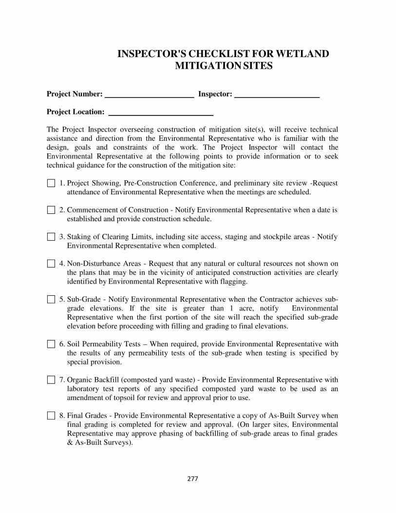
277
INSPECTOR'S CHECKLIST FOR WETLAND
MITIGATION SITES
Project Number: Inspector:
Project Location:
The Project Inspector overseeing construction of mitigation site(s), will receive technical
assistance and direction from the Environmental Representative who is familiar with the
design, goals and constraints of the work. The Project Inspector will contact the
Environmental Representative at the following points to provide information or to seek
technical guidance for the construction of the mitigation site:
1. Project Showing, Pre-Construction Conference, and preliminary site review -Request
attendance of Environmental Representative when the meetings are scheduled.
2. Commencement of Construction - Notify Environmental Representative when a date is
established and provide construction schedule.
3. Staking of Clearing Limits, including site access, staging and stockpile areas - Notify
Environmental Representative when completed.
4. Non-Disturbance Areas - Request that any natural or cultural resources not shown on
the plans that may be in the vicinity of anticipated construction activities are clearly
identified by Environmental Representative with flagging.
5. Sub-Grade - Notify Environmental Representative when the Contractor achieves sub-
grade elevations. If the site is greater than 1 acre, notify Environmental
Representative when the first portion of the site will reach the specified sub-grade
elevation before proceeding with filling and grading to final elevations.
6. Soil Permeability Tests – When required, provide Environmental Representative with
the results of any permeability tests of the sub-grade when testing is specified by
special provision.
7. Organic Backfill (composted yard waste) - Provide Environmental Representative with
laboratory test reports of any specified composted yard waste to be used as an
amendment of topsoil for review and approval prior to use.
8. Final Grades - Provide Environmental Representative a copy of As-Built Survey when
final grading is completed for review and approval. (On larger sites, Environmental
Representative may approve phasing of backfilling of sub-grade areas to final grades
& As-Built Surveys).
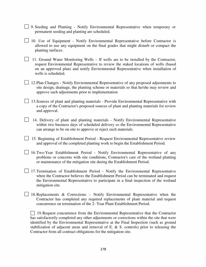
278
9. Seeding and Planting - Notify Environmental Representative when temporary or
permanent seeding and planting are scheduled.
10. Use of Equipment - Notify Environmental Representative before Contractor is
allowed to use any equipment on the final grades that might disturb or compact the
planting surfaces.
11. Ground Water Monitoring Wells – If wells are to be installed by the Contractor,
request Environmental Representative to review the staked locations of wells (based
on an approved plan) and notify Environmental Representative when installation of
wells is scheduled.
12. Plan Changes - Notify Environmental Representative of any proposed adjustments to
site design, drainage, the planting scheme or materials so that he/she may review and
approve such adjustments prior to implementation.
13. Sources of plant and planting materials - Provide Environmental Representative with
a copy of the Contractor's proposed sources of plant and planting materials for review
and approval.
14. Delivery of plant and planting materials - Notify Environmental Representative
within two business days of scheduled delivery so the Environmental Representative
can arrange to be on site to approve or reject such materials.
15. Beginning of Establishment Period - Request Environmental Representative review
and approval of the completed planting work to begin the Establishment Period.
16. Two-Year Establishment Period - Notify Environmental Representative of any
problems or concerns with site conditions, Contractor's care of the wetland planting
or maintenance of the mitigation site during the Establishment Period.
17. Termination of Establishment Period - Notify the Environmental Representative
when the Contractor believes the Establishment Period can be terminated and request
the Environmental Representative to participate in a final inspection of the wetland
mitigation site.
18. Replacements & Corrections – Notify Environmental Representative when the
Contractor has completed any required replacements of plant material and request
concurrence on termination of the 2- Year Plant Establishment Period.
19. Request concurrence from the Environmental Representative that the Contractor
has satisfactorily completed any other adjustments or corrections within the site that were
identified by the Environmental Representative at the Final Inspection (such as ground
stabilization of adjacent areas and removal of E. & S. controls) prior to releasing the
Contractor from all contract obligations for the mitigation site.
279
SECTION 606 – SOIL RETENTION COVERINGS
General
This work shall consist of furnishing and placing protective covering material for soil
retention including seed, fertilizer, lime, topsoil and water.
Construction
The Contractor shall apply two inches of topsoil to areas to receive soil retention
coverings. Topsoil shall be rolled or tamped before being shaped to match cross sections
on the plans. During the shaping operation, a seedbed approximately ¾ inch deep shall
be provided.
The Inspector should ensure that stones, roots and other objects are removed from the
seedbed prior to installation of the covering.
Seed shall be applied as required in Section 603, except that mulch is not required. Seed,
lime and fertilizer must be placed prior to installation of the covering.
The soil retention covering is to be installed in accordance with the Standard Drawings
and manufacturers recommendations.
Inspectors should verify that the soil retention coverings are listed on the approved list of
materials.
Method of Measurement
Protective coverings and soil retention mats are measured in square yards of area covered
and paid for at the contract unit price per square yard. This price shall include complete
installation, stapling, shaping of ditches, preparing seedbeds, and applying topsoil, lime,
fertilizer, seed and water.
Inspector’s Checklist
1. Does the Contractor place 2 inches of topsoil shaped in accordance with the cross
sections?
2. Does the Contractor apply seed, fertilizer and lime prior to installing protective
covering?
3. Is the soil retention covering installed in accordance with the Standard Drawings and
manufacturer’s recommendations?
280
4. Is the protective covering applied in the direction of water flow and lapped a
minimum of 6 inches?
5. Does the Contractor bury the top of the anchor slot 6 to 12 inches?
6. Are the staples the proper size and length and placed properly according to the
Standard Drawings?
7. Does the Contractor trench in the edges of the coverings a minimum of 6 inches?
8. Does the Contractor water the seeded areas after the covering was installed?
281
SECTION 607 – HERBICIDE SPRAYING
General
This work consists of spraying an approved herbicide for control of weeds. Handling and
application of herbicides is of a critical nature in that the materials are quite toxic and
often non-selective as to vegetation killed
The Inspector should consult the District Environmental Manager prior to herbicides
being applied and should keep thorough records on all applications of herbicides. The
Inspector should ensure that the Contractor takes precautions when spraying, filling or
flushing equipment to prevent contamination of streams, lakes, or ponds.
Application
Herbicide shall be applied in accordance with the manufacturer's recommendation.
Herbicide shall not be applied when the temperature is above 85 degrees F or below 60
degrees F. Spraying should not be applied when the vegetation is wet, when rain is
imminent within 6 hours or when excessively windy.
Method of Measurement
Herbicide spraying is measured in units of 1000 gallons of mixture and is paid at the
contract unit price per 1000 gallons.
282
SECTION 608 – MOWING
General This work consists of mowing areas as designated by the Engineer. Mowing is important
not only for aesthetics but also to control weeds and promote the growth and spread of
more desirable grasses. Areas should be mowed to a height no less than 4 inches.
Method of Measurement When specified as a contract item, mowing is paid for by the hour.

283
TRAFFIC CONTROL DEVICES
284
SECTION 700 - GENERAL
Description
This section is for general construction items of work common to signing, signals and
lighting.
Working Drawings
The Contractor shall submit seven copies of working drawings and catalog cuts including
any design calculations of each item or piece of equipment to be furnished and installed
on the project in accordance with Section 105. In lieu of submitting working drawings
the Contractor may submit a letter indicating the brands, types, and models of equipment
along with bid item numbers and approval numbers for equipment on the Department's
"Pre-Approved Traffic Control Device Listing." Working drawing submittals and the
listing for pre-approved items are to be forwarded to the Regional Traffic Engineer for
review.
Procedures
Grounding
The Contractor may use NEC approved methods of grounding metal items other than
what is shown on the plans or in the Road and Bridge Standards. However, the method
shall result in a resistance to ground of no more than 25 ohms.
Foundation
The Inspector must verify that the staked location of the foundation is correct. After
excavation, the Inspector must verify that the base upon which the foundation will be
placed is suitable material. Reinforcing steel must be placed and anchored in accordance
with the Road and Bridge Standards or the plans.
Concrete foundations are to be constructed as shown in the Road and Bridge Standards,
the plans and the working drawings.
The size of the conduit should be checked and the placement should be as shown on the
plans, working drawings and Road and Bridge Standards. Ensure the proper placement
of anchor bolts to achieve correct alignment and elevation.
The top of the foundation is to be flush when mounted in or adjacent to sidewalks and 4
inches above the ground level in all other areas. The foundation is to be backfilled and
compacted as specified.
285
Concrete foundations must achieve 3000 psi compressive strength prior to erection of any
item on them.
Erection of Poles, Post and Sign Structures
The location of all signs, signal, and lighting poles are to be staked by the Contractor and
checked by the Engineer and the Inspector before construction. No major location
change is to be made without approval of the Regional Traffic Engineer.
Necessary precautions must be taken to reduce damage to galvanized, painted, or finished
aluminum surfaces.
Hardware should be checked for compliance with Specifications and shop drawings upon
arrival on the project.
Poles are to be installed plumb after installation of their loads. Plumbness may be
achieved by the use of nuts and flat washers above and below the base plates, as allowed
by the Road and Bridge Standards.
If any pole, structure, or span wire is to be installed within 10 feet of an electrical power
line, the Engineer is to be notified immediately and no work is to proceed until advised
by the Engineer that it is safe to do so.
Non-corrosive metal identification tags are to be installed and marked as specified.
Poles are to be provided with 3 inch by 5 inch hand holes complete with covers and
gaskets. Hand holes are to be attached with non-corrosive tap screws and are to face
away from the roadway.
Conductor Cables
Conductor cables in conduit more than 100 feet long shall be installed with the use of an
approved lubricant. Bends in conductor cables shall have a bend radius of at least 5 times
the diameter of the cable.
Splices in signal and interconnect conductor cables will not be permitted. Splices in
lighting conductor cables will be permitted only at accessible locations. Splices in
service entrance conductor cable are only permitted for connection to the utility
company’s service conductor cable.
Termination of cables is permitted only in a master control cabinet, local controller
cabinet or a terminal enclosure. Each wire of a cable must be connected to a terminal
post.
The Contractor is required to perform a Meggar test on interconnect cables as specified.
286
Prior to energizing an electrical system, the Contractor is to demonstrate that the system
is clear and free from short circuits and unintentional grounds.
Conductor cables are to be marked and identified at accessible locations as specified.
Conduit Systems
Conduits shall be PVC, fiberglass or metal as specified. Ends of conduit that must be
field cut shall be reamed smooth. Conduit sections shall be connected with couplings so
that the ends will abut squarely inside the coupling. Joint sealing solvent shall be as
recommended by the manufacturer of the conduit.
Conduits shall be installed continuous and watertight between outlets and so that
moisture will drain properly to junction boxes or drainage tees.
After installation, each conduit is to be tested for obstructions. When conduits are clear
of obstructions, empty conduits shall be equipped with pull ropes as specified.
Open ends of unused conduit shall be plugged or capped. Where conduit crosses an
expansion joint, conduit shall be provided with an expansion fitting. Metal conduit shall
be bonded.
Exposed conduit systems shall not have more than 4 bends between outlets and the
angular sum of the bends shall not exceed 360 degrees.
Buried conduit systems shall be installed in straight lines between outlets. When
obstructions are encountered, the obstruction shall be bypassed in accordance with the
standard drawings. Required bends shall have a radius of at least 5 feet.
When conduit is installed under a roadway and open cutting is not permitted, the conduit
shall be installed in a pipe sleeve that has been jacked or bored.
Electrical Service
The electrical service location and date electrical service is needed should be determined
early. The request for electrical service should be sent to the Regional Traffic Engineer
with the following information as soon as possible:
1. Location of electrical service
2. Voltage and number of phases needed (120/240 single phase, 240/480
single phase, 277/480 three phase etc.)
3. Installation - above or below ground
287
4. Name of utility company servicing the project area and pole number
identified as the power source.
5. Date electrical service is needed.
Inspector’s Checklist
1. Does the material meet the requirements as specified?
2. Are working drawings submitted as required?
3. Do ground rounds include a No. 6 bare copper wire and ground wire clamp?
4. Are concrete foundations constructed as required?
5. Did concrete foundation reach the required 3000 psi compressive strength prior to
erection of items on them?
6. Is the location of each foundation verified to be correct?
7. Are non-corrosive metal tags attached as specified?
8. Are hand holes provided as specified?
9. Are conduit systems and conductor cables installed as specified?
288
SECTION 701 – TRAFFIC SIGNS
General The proper use of traffic signs is critical to ensure the safety of the traveling public.
Materials used must conform to the Specifications and proper location and installation
must be in accordance with the Manual for Uniform Traffic Control Devices (MUTCD).
Inspectors should contact the Regional Traffic Engineer for assistance as needed.
Materials The Inspector is to ascertain that all materials have been approved for use by test reports
or "Certificates of Compliance" and documented in the Materials Notebook. Visual
inspection is to be made of the condition of material at time of arrival and for compliance
with plans, Specifications, and approved drawings. Should a question arise in regard to
acceptability of a material or finished sign, the Inspector is to refer the matter to the Area
Construction Engineer for clarification. Substitution of a similar item for the specified or
previously approved item is not to be permitted unless specifically authorized in writing
by the Engineer.
Procedures Fabrication
Sign panels are fabricated using 0.100- inch thick aluminum. The panels must be
smooth, flat and free of burrs and splinters.
With few exceptions, reflective sheeting shall be 4 x 4 feet on sign panels 16 square feet
or more in area. Joints or laps are not permitted on sign panels less than 16 square feet in
area except as allowed by the Specifications.
When more than one width of sheeting is applied to a panel, sheeting edges shall form a
vertical butt joint or overlap not more than 3/8 inch. If horizontal joints are used, the
bottom edge of the top sheet shall lie over the top of the next lower sheeting with a lap of
no more than 3/8 inch.
Legends on each sign face are to be checked upon arrival on the project to ensure correct
copy. Checks of letter size and spacing for conformance with shop drawings are to be
made before erection. Each sign panel is to be clean when it is erected.
The finished sign shall have no cracks gaps, streaks, wrinkles, blisters, buckles, tears,
warps, or discoloration.
Transporting and Storing
289
Inspectors should verify that signs are being transported and stored as specified to ensure
damage does not occur to the signs prior to installation.
Erection
The Inspector must verify that the clearance for overhead and bridge mounted signs is not
less than 19 feet and not more than 21 feet from the bottom of the sign to the roadway
crown.
Panels are to be securely fastened to posts or supports and erected plumb. Stud breakage
of not more than 10 percent shall be repaired. If breakage exceeds 10 percent, the
Inspector must reject the sign panel.
Ground mounted signs are to be installed at a horizontal angle of 93 degrees between the
face of the sign and the centerline of the roadway. Vertical and horizontal spacing
between signs shall be 1 inch.
Neoprene gaskets 1/16 inch thick are to be used between galvanized steel post clamps
and the framing unit.
Damage to reflective sheeting shall be patched or replaced as specified.
Method of Measurement
Sign panels are measured in square feet of surface area. The price includes background
sheeting, sign messages and framing units.
Inspector’s Checklist
1. Do all materials delivered have Certificates of Compliance or test reports?
2. Are sign panels smooth, flat, correct thickness, degreased and etched, edges straight
and smooth, and corner radius true and proper?
3. Are Zee bars the proper size, straight and properly spaced?
4. Does sheeting material have joints, splices, and laps as specified?
5. Are the finished sign panels free from cracks, gaps, streaks, wrinkles, blisters,
discoloration, buckles, and warps and have a smooth surface of uniform color?
6. Are all messages and symbols correct and conform to the requirements of the
MUTCD?
7. Were signs transported and stored properly?

290
8. Are signs installed as required?
9. Are signs panels covered as required when installed prior to being needed?
291
SECTION 702 – DELINEATORS
General
The proper installation of delineators on guardrail, barriers, parapets, railings, and along
the roadside is necessary to ensure the safety of the traveling public. Inspectors should
refer to the Road and Bridge Standards or the plans for proper placement.
Procedures
Road edge delineators are to be placed as indicated on the plans and on the Standard
Drawings. Inspectors should pay particular attention to the distance the delineator is
installed from the edge of roadway, the height of the reflector and the spacing.
Delineators installed on guardrail, median barriers and railings must be installed on a
clean, dry surface. The Inspector must ensure that loose material and dirt are removed
from the surface where the delineator is to be installed.
Delineators installed on barriers shall be installed on top of the barrier wall. Exceptions
are when barrier height is greater than 36 inches, barriers with glare screens or handrail
attached and barriers in work zones. These delineators shall be installed 25 inches above
the roadway and positioned so the vertical plane faces oncoming traffic.
Delineators for guardrail shall be installed on the web of posts. If blockouts are used, the
delineator shall be installed on the web of the blockouts.
Delineators on guardrail and barriers are to be installed on 80 foot centers, unless
otherwise indicated. When the correct center to center spacing cannot be achieved due to
guardrail post spacing, the delineator spacing shall not exceed 80 feet.
Method of Measurement
Road edge delineators are measured in units of each installed. Guardrail, barrier, and
railing delineators are considered incidental to the construction of those items and are not
measured for separate payment.
Inspectors Checklist
1. Are delineators the same color as the adjacent pavement markings?
2. Are road edge delineators installed at the specified distance from edge of pavement?
3. Are delineators installed at the specified height?
4. Are delineators installed at the specified spacing?
292
SECTION 703 – TRAFFIC SIGNALS
General
Work under this section consists of furnishing, installing, modifying, relocating, or
removing traffic signal equipment. Since this work differs so much from normal
roadwork, it is desirable that the Inspector make a special effort to learn the terminology
unique to this work and to contact the Regional Traffic Engineer for advice. This
knowledge is necessary in order to communicate effectively with the Contractor's
personnel.
The Contractor should not be allowed to disturb existing facilities until he is prepared to
continuously prosecute the work to completion. When existing signals are to be altered,
they should be kept in regular operation as long as practicable. During any "down time"
while signals are being modified or replaced, the Contractor is to provide other means of
controlling traffic. Once the Contractor begins work on any system, he is responsible for
all maintenance for that system until accepted by the Department. This is not intended to
hold the Contractor responsible for all costs incurred from damages completely beyond
his control.
Equipment
Equipment provided by the Contractor shall be certified by the manufacturer as
conforming to the requirements of NEMA TS-1. Controllers are to be furnished
completely housed in a waterproof cabinet. The manufacturer's instructions for installing
and maintaining the equipment shall be provided by the Contractor.
Inspectors should verify that the manufacturer's certifications and instructions have been
furnished.
The Contractor is required to provide at least 15 hours of training to Department
personnel in the operation, timing, maintenance, and repair of signal equipment.
Prosecution of Work
Inspectors must ensure that the operation of existing traffic signals is not discontinued
without the approval of the Engineer.
The Contractor is responsible for maintaining traffic at all times during installation.
Equipment Color
The color of signal heads shall be Federal Yellow, except the inside of the visors shall be
flat black. Backplates and leveling attachments shall be flat black.
293
Mounting Controller Cabinets
Pole Mounted Controller Cabinets are to be mounted to metal poles using brackets
secured by encircling clamps and to wood poles by lag screws and plates bolted through
the back of the cabinet.
Ground mounted cabinets are to be installed on concrete foundations.
Installing Signal Heads
When a new or refurbished signal head is installed, the Contractor shall cover the signal
head with a durable non-transparent cover and maintain the cover until the signal head is
put into operation.
The bottom of the housing of pedestal mounted or bracket mounted signal face adjacent
to the pavement shall be at least 8 feet but not more than 15 feet above the sidewalk or
the pavement grade at the center of the roadway.
When traffic signal heads are suspended over roadways the lowest point shall be at least
15 feet for mast arm installations and 16 feet for span wire installation above the
pavement grade at the center of the roadway. The bottom of the housing shall not be
more than 19 feet for either type of installation.
Pedestrian signal heads shall be mounted at least 7 feet but not more than 10 feet above
the sidewalk. They shall be orientated in such a manner that they are visible to the
pedestrians using the crosswalk.
Backplates shall be attached with bolts, washers and lock nuts or self-tapping screws and
washers. For 3 section signal heads, at least 8 bolts or screws are required. For 4 section
signal heads, at least 10 bolts or screws are required and 12 bolts or screws for 5 section
assemblies.
Illuminated signs used to control right or left turns shall be installed directly over or
adjacent to the affected traffic lane. They shall be mounted at the same height as
standard traffic signals. When mounted with other traffic control signs or signals, there
should be adequate clearance between them so as to prohibit contact.
Detectors are to be installed within 2 feet of the location shown on the plans. Splices in
loop or magnetic detector conductors are only allowed in signal junction boxes. Detector
and detector lead-in cables are to be installed coiled with enough coiled length to extend
2 feet above the junction box. Detector and detector lead-in cables shall be tagged as
specified.
Installation of magnetic detectors shall be in a heavy-wall PVC conduit 3 inches in
diameter in a trench cut to 15 inches in depth and surrounded by at least 3 inches of sand.
294
Magnetic detector circuits are not to be installed in the same cable sheath with conductors
carrying signal power.
Slots for inductive loop detectors are sawed into the pavement, cleaned with pressurized
water and dried with compressed air before loop conductors are installed and sealed with
a Department approved sealer. Loops shall be installed in the presence of the Engineer.
Pedestrian detectors are mounted on supports as shown on the plans. Breakaway
connectors must be installed in the hand hole on conductor cables for pedestrian detectors
on pedestal poles.
Rigging Details
Overhead span wires are attached to either a 5/8 or 3/4 inch thimbleye, depending upon
the diameter of the span wire. Span wires are not to be spliced.
Down guys are used on wood poles and shall be the same type of cable as used in span
wires. They are attached in the same manner and same height as span wires. Lateral
guys placed over the roadway are to be strung to maintain a vertical clearance of at least
17 feet 6 inches.
Testing Equipment
After energizing signal installations the Contractor is required to demonstrate that the
electrical components are in proper working order. Upon completion of the electrical
tests the Contractor shall conduct a demonstration test of each signalized intersection for
30 continuous days. If any components need to be replaced or repaired, that portion shall
be subject to an additional 30 days of testing.
Testing of traffic signal system master controllers and system coordination shall be
conducted after demonstration test of each signalized intersection.
Prior to final acceptance, the Contractor must furnish written certification that the system
control equipment has been installed in accordance with the manufacturer's
specifications.
Method of Measurement
Span wire, tether wire, and saws cuts are measured in linear feet. Conductor cables are
measured in accordance with Section 700. All other components are measured in units of
each.
Inspector's Checklist
1. Are traffic signals installed as specified and as on the plans?
295
2. Are controllers installed in waterproof cabinets?
3. Did the Contractor furnish instructions for installing and maintaining the equipment?
4. Is the minimum vertical clearance maintained?
5. Are backplates installed as specified?
6. Are loop detectors installed within 2 feet of the location shown on the plans?
7. Are slots for loop detectors saw cut, cleaned with pressurized water, and dried with
compressed air?
8. Were loops installed in the presence of the Engineer?
9. Is loop sealant installed flush with the finished surface and completely cover the
loops?
10. Are pedestrian detectors mounted as shown on the plans and are breakaway
connectors installed in the hand holes?
11. Did the Contractor perform the proper tests and demonstrations?
12. Are signal heads that are not in operation properly covered?
296
SECTION 704 – PAVEMENT MARKINGS AND
MARKERS
General
Normally the last item of work on pavement structures is the installation of pavement
markings and markers. Yet, the correct installation of these items is very important for
the safety of the traveling public.
If there is not a Pavement Marking plan sheet for the project and if the Standards don not
address the pavement marking needs, the Inspector should contact the Regional Traffic
Engineering Office for assistance.
The Inspector should verify that the Contractor has a certified Pavement Marking
Technician on the project prior to installation of pavement markings or markers.
Materials
Pavement marking materials are required to be tracked using an approved inventory
tracking system. Inspectors should verify that the Contractor has furnished a certification
of such as required in Section 704. A copy of the certified delivery ticket must be given
to the Inspector upon delivery of the material.
Pavement Markings
Pavement markings on new roadways are to be installed prior to opening to traffic. On
roadways already open to traffic, pavements markings must be installed within the
specified time limits. If the Contractor cannot install permanent pavement markings
within the specified time limit, Type D construction pavement markings shall be installed
within the same timeframe. The cost of installing, maintaining, and removing the
construction pavement markings shall be borne by the Contractor.
The location of pavement markings is established by premarking the roadway. The
premarking material may be Type D removable tape, chalk, or lumber crayon. Special
pavement markings must be made with either chalk or lumber crayons. Premarkings
must be of the same general color of the finished markings.
The Contractor is required to perform quality control testing for application thickness and
glass bead rate at the beginning of each day and every three hours thereafter. This testing
is to be performed in the presence of the Inspector. Testing procedures are outlined in
VTM-94.
A daily log (Form C-85) is to be maintained by the Contractor for both temporary and
permanent pavement markings. This log is to be completed for each day and delivered to
the Inspector at the end of each workday.
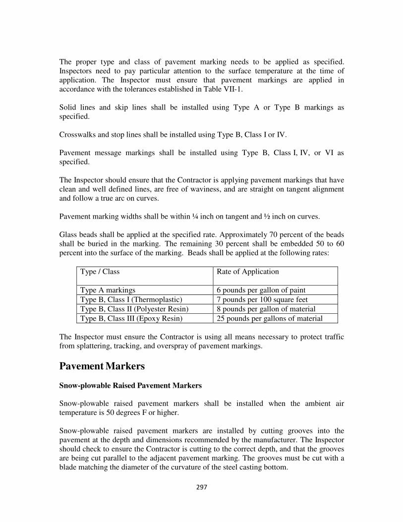
297
The proper type and class of pavement marking needs to be applied as specified.
Inspectors need to pay particular attention to the surface temperature at the time of
application. The Inspector must ensure that pavement markings are applied in
accordance with the tolerances established in Table VII-1.
Solid lines and skip lines shall be installed using Type A or Type B markings as
specified.
Crosswalks and stop lines shall be installed using Type B, Class I or IV.
Pavement message markings shall be installed using Type B, Class I, IV, or VI as
specified.
The Inspector should ensure that the Contractor is applying pavement markings that have
clean and well defined lines, are free of waviness, and are straight on tangent alignment
and follow a true arc on curves.
Pavement marking widths shall be within ¼ inch on tangent and ½ inch on curves.
Glass beads shall be applied at the specified rate. Approximately 70 percent of the beads
shall be buried in the marking. The remaining 30 percent shall be embedded 50 to 60
percent into the surface of the marking. Beads shall be applied at the following rates:
Type / Class Rate of Application
Type A markings 6 pounds per gallon of paint
Type B, Class I (Thermoplastic) 7 pounds per 100 square feet
Type B, Class II (Polyester Resin) 8 pounds per gallon of material
Type B, Class III (Epoxy Resin) 25 pounds per gallons of material
The Inspector must ensure the Contractor is using all means necessary to protect traffic
from splattering, tracking, and overspray of pavement markings.
Pavement Markers
Snow-plowable Raised Pavement Markers
Snow-plowable raised pavement markers shall be installed when the ambient air
temperature is 50 degrees F or higher.
Snow-plowable raised pavement markers are installed by cutting grooves into the
pavement at the depth and dimensions recommended by the manufacturer. The Inspector
should check to ensure the Contractor is cutting to the correct depth, and that the grooves
are being cut parallel to the adjacent pavement marking. The grooves must be cut with a
blade matching the diameter of the curvature of the steel casting bottom.
298
The steel casting is to be bonded into the pavement as recommended by the
manufacturer. The bonding material shall be from the Department's approved list of
materials.
The nose of the casting must be flush with the pavement surface. The height of the
marker shall be installed approximately ½ inch above the pavement surface.
The top of the reflector shall be mounted flush with the top of the casting.
Raised Pavement Markers
Raised Pavement Markers shall be bonded to the pavement using the manufacturer's
recommendation. Bonding material shall be from the Department’s approved list of
materials, except that epoxy shall not be used on asphalt concrete pavements.
Method of Measurement
Pavement Line markings are measured in linear feet of markings applied. Message
markings are measured per each for the type of message. Pavement markers are
measured in units of each.
Inspector’s Checklist
1. Does the Contractor use an approved inventory tracking system and provide copies of
certified delivery tickets?
2. Does the Contractor have a certified Pavement Marking Technician present during
pavement marking operations?
3. Is premarking accomplished as specified?
4. Is quality control testing performed as specified?
5. Does the Contractor install markings within the specified time limits?
6. Is the Contractor installing the proper color markings in accordance with the Manual
for Uniform Traffic Control Devices?
7. Is the Contractor installing markings in accordance with Table VII-1?
8. Did the Contractor maintain and submit to the Inspector Form C-85 for each days
work?
9. Is the Contractor protecting traffic from damage due to pavement marking
operations?

299
10. Is the pavement surface dry for 24 hours prior to pavement markings being applied?
11. Are glass beads applied at the specified rate?
12. Are grooves for snow-plowable pavement raised pavement markers cut as specified?
13. Are the noses of snow-plowable raised pavement markers installed flush with the
pavement surface?
14. Is the height of snow-plowable pavement raised pavement markers approximately ½
inch above the pavement surface?
300
APPENDIX A
DEPARTMENT EQUIPMENT
Engineering Equipment
Inspection on many projects requires the use of engineering instruments such as levels,
theodolites, electronic measuring devices or total stations. These instruments are assigned
to the District Construction Management staff on construction projects by the District
Survey Party Supervisor and reassigned to a particular construction project.
Instruments are to be tested for adjustment at regular intervals. This should be done by
performing field tests by the person using the instrument. However, the Project Inspector
is charged with the responsibility of seeing that it is done and that the instruments are
kept in adjustment. The instrument should never be disassembled or adjusted except by
an authorized instrument repairman.
When not in use, instruments should be kept in their respective boxes. Never leave an
instrument "set up" unless an employee of the Department is present to protect it. Before
climbing a fence or similar obstacle, the instrument should be placed on the other side
with the tripod legs spread. Under no circumstances should a boxed instrument be placed
in a vehicle so that it can bounce around or overturn.
Instruments, under ordinary circumstances, should be maintained and carried in their
original storage boxes. Should circumstances require that an instrument be shipped, it
should be clamped on its spindle and paper packed carefully and snugly around it in the
box.
The magnetic needle must be kept clamped at all times, except when a compass reading
is being taken. After such readings are made and recorded, the needle should immediately
be reclamped.
Precaution should be used to ensure that engineering equipment is not exposed to any
form of precipitation. If the instrument has been exposed to falling weather, it must be
wiped dry as soon as possible, in any event, as soon as brought indoors.
Tripods should be protected from the weather when not in use and the threads protected
by using the tripod cap. Instrument boxes should be kept clean and free of dust. Loose
objects shall not be stored or transported in instrument boxes.
Engineering instruments and laboratory equipment are delicate, precision equipment.
Results are reliable only when instruments and equipment are properly used, handled, and
maintained. Remember that instrument and equipment repair work is costly and time
consuming.
301
The Project Inspector is responsible for all instruments assigned to the project. In case of
theft or accident caused by negligence or misuse, the person responsible can be assessed
the cost of replacement or repairs, unless conclusive evidence is given that the occurrence
was unavoidable. For these situations, the Project Inspector must make a written report
to the Construction Manager explaining the details as follows:
1. Name of person in charge of instrument and person directly responsible.
2. Location where accident or theft occurred.
3. Cause, give full information.
4. Make and serial number of instrument.
5. Extent of damage.
6. General condition of instrument exclusive of damage.
Vehicular Equipment
An employee should not operate any piece of mechanical or motorized equipment unless
familiar with the correct operating procedures. Regulations prohibit any employee from
operating any motorized equipment unless he has an approved operator's card for that
particular type of equipment. These cards may be secured from the Resident Mechanic.
Any accident involving State equipment and causing personal injury or property damage
should be reported to and investigated by the State Police. Insist upon an investigation by
the State Police before leaving the scene of an accident.
A "Driver's Report of Equipment Accident" is furnished with every piece of State
equipment. These indicate the information the operator must secure if that piece of
equipment is involved in an accident. This information should be delivered to the
residency office.
Remember that all Department-owned vehicles are public property. You, as an operator,
are expected to set a good example by:
1. Observing all traffic laws.
2. Practicing courtesy in driving.
3. Maintaining all safety devices in operating condition.
4. Keeping the vehicle properly serviced and clean.
302
5. Practicing defensive driving.
6. Abiding by all current Safety Rules.
7. Properly securing the vehicle when unattended.
Publications
Publications are available from the residency and district offices. All inspection
personnel should have available the following items:
1. Road and Bridge Specifications book.
2. Road and Bridge Standards, Volumes I and II.
3. Construction Manual.
4. Inspection Manual
5. Manual of Instruction, Materials Division.
6. Work Area Protection Manual.
7. Erosion and Sedimentation Control Handbook.
8. Guard Rail Installation Training Manual.
9. Claims Manual
10. Current Instructional Memorandum.
11. Post-Construction Manual
12. Survey Manual
WEB Sites
The following web sites are available to assist in the performance of Inspection duties:
1. http://www.virginiadot.org/business/const/default.asp
2. \\Comatapp01\MaterialsNet\Default.htm
3. http://www.virginiadot.org/business/resources/const/Inspection_Manual.pdf
4. http://www.extranet.vdot.state.va.us/locdes/GRIT/main.htm

303
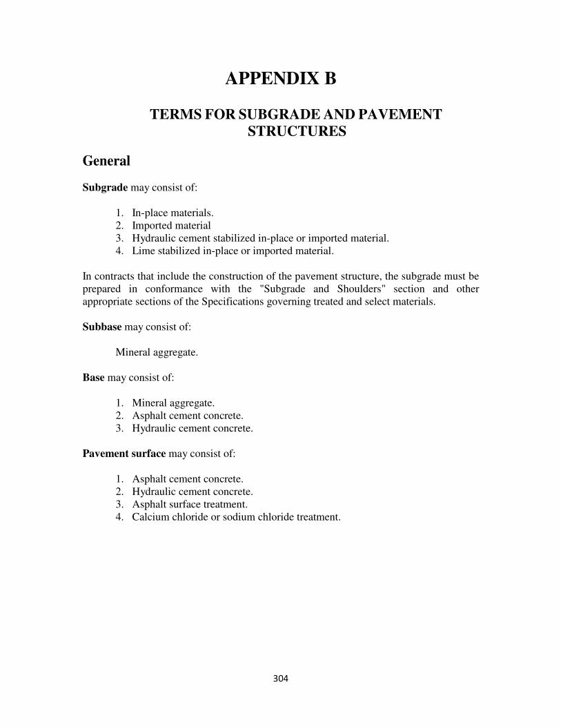
304
APPENDIX B
TERMS FOR SUBGRADE AND PAVEMENT
STRUCTURES
General
Subgrade may consist of:
1. In-place materials.
2. Imported material
3. Hydraulic cement stabilized in-place or imported material.
4. Lime stabilized in-place or imported material.
In contracts that include the construction of the pavement structure, the subgrade must be
prepared in conformance with the "Subgrade and Shoulders" section and other
appropriate sections of the Specifications governing treated and select materials.
Subbase may consist of:
Mineral aggregate.
Base may consist of:
1. Mineral aggregate.
2. Asphalt cement concrete.
3. Hydraulic cement concrete.
Pavement surface may consist of:
1. Asphalt cement concrete.
2. Hydraulic cement concrete.
3. Asphalt surface treatment.
4. Calcium chloride or sodium chloride treatment.
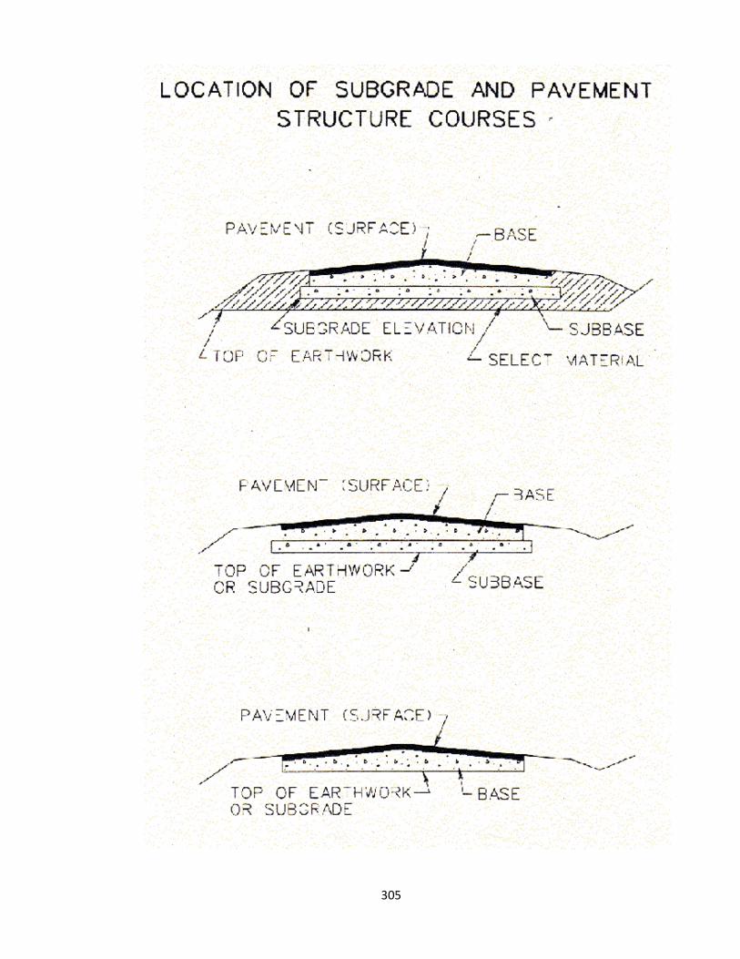
305

306
APPENDIX C
PROJECT RECORDS
General
The “keeping” of project records, including the preparation, assembly, and preservation
of such records is considered to be one of the most important duties and responsibilities
which the Engineer delegates to the Inspector.
Field notes constitute a written record of pertinent information, measurements, and
observations regarding the project. They should be kept according to uniform practices.
Detailed sketches should be shown on daily diary sheets.
Project diaries and project records are to be reviewed by the Construction Manager, Area
Construction Engineer or District Construction Engineer on at least a monthly basis. A
record of this review, signed by the reviewer, will be made part of the project records and
a summary of the findings of this review shall be made in the project diary.
Accuracy
Record exactly what was done at the completion of the item rather than depending on
memory at a later time. When it is necessary to add data to notes previously prepared,
the additional item should be dated and initialed. Always enter notes directly into the
record.
Clarity
Plan your entries so that data can be orderly arranged. Do not make ambiguous
statements. Show neatly dimensioned sketches for clarity. Assume that the person who
will use your notes has no familiarity with the work.
Legibility
Use standard symbols and abbreviations to keep notes concise. Use plain lettering to
avoid confusion.
Completeness
Show all pertinent measurements and observations. Use a degree of accuracy consistent
with the operation. If in doubt about the need for the data, record it.
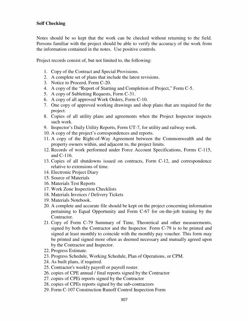
307
Self Checking
Notes should be so kept that the work can be checked without returning to the field.
Persons familiar with the project should be able to verify the accuracy of the work from
the information contained in the notes. Use positive controls.
Project records consist of, but not limited to, the following:
1. Copy of the Contract and Special Provisions.
2. A complete set of plans that include the latest revisions.
3. Notice to Proceed, Form C-20.
4. A copy of the “Report of Starting and Completion of Project,” Form C-5.
5. A copy of Subletting Requests, Form C-31.
6. A copy of all approved Work Orders, Form C-10.
7. One copy of approved working drawings and shop plans that are required for the
project.
8. Copies of all utility plans and agreements when the Project Inspector inspects
such work.
9. Inspector’s Daily Utility Reports, Form UT-7, for utility and railway work.
10. A copy of the project’s correspondences and reports.
11. A copy of the Right-of-Way Agreement between the Commonwealth and the
property owners within, and adjacent to, the project limits.
12. Records of work performed under Force Account Specifications, Forms C-115,
and C-116.
13. Copies of all shutdowns issued on contracts, Form C-12, and correspondence
relative to extensions of time.
14. Electronic Project Diary
15. Source of Materials
16. Materials Test Reports
17. Work Zone Inspection Checklists
18. Materials Invoices / Delivery Tickets
19. Materials Notebook.
20. A complete and accurate file should be kept on the project concerning information
pertaining to Equal Opportunity and Form C-67 for on-the-job training by the
Contractor.
21. Copy of Form C-79 Summary of Time, Theoretical and other measurements,
signed by both the Contractor and the Inspector. Form C-79 is to be printed and
signed at least monthly to coincide with the monthly pay voucher. This form may
be printed and signed more often as deemed necessary and mutually agreed upon
by the Contractor and Inspector.
22. Progress Estimate.
23. Progress Schedule, Working Schedule, Plan of Operations, or CPM.
24. As built plans, if required.
25. Contractor's weekly payroll or payroll roster.
26. copies of CPE annual / final reports signed by the Contractor
27. copies of CPEi reports signed by the Contractor
28. copies of CPEs reports signed by the sub-contractors
29. Form C-107 Construction Runoff Control Inspection Form
308
Project Diary
The Project Inspector is required to maintain an electronic diary in Site Manager for each
contract. The electronic diary entries will be made daily and must be completed by noon
on the following day.
The project diary should contain a day-to-day record of all significant occurrences
relating to the project. It must be complete, concise, and accurate. The Project Diary
should include the following information:
1. Day of week, month, date of the month and year.
2. Daily weather conditions and temperature range.
3. Record of instructions given to the Contractor. In the event a controversy arises,
record all pertinent information.
4. Information relative to the progress of work being done by the Utility Company in
moving their facilities (lines, cables, poles, pipes,). Note causes for delay and its
effect on the Contractor's progress.
5. Pay items
6. Note any authorized extra work, force account work, etc. being performed and
refer to Inspector's Daily Report for detailed information.
7. Any unusual occurrences, resulting in personal injury or property damage, such as
damage caused by blasting operations or Contractor's equipment.
8. When physical conditions of the work are encountered that are unusual or are
materially different from those expected, record the following information:
i. Detailed description of the unusual conditions encountered.
ii. An estimate of the net effect the unusual conditions have upon the
progress of the work.
iii. The increase in the working force required to overcome
the unusual conditions encountered.
iv. Equipment and materials used and other pertinent
information which would be of value should a claim result.
9. If construction progress is not satisfactory, entries in the diary should substantiate
this fact. In addition to the information previously listed the diary should include:
309
10. The actual activities of the Contractor.
11. The rate that the Contractor is performing these operations.
12. The activities that the Contractor could and should be accomplishing but is not.
13. The efforts made at the project level to have the Contractor improve upon his
progress.
Note: The opinion of the Inspector is valuable when it is documented by
facts. Do not hesitate to list the full particulars in the diary. Seemingly
minor details may become important at a later date.
14. Periodic wage rate interviews with Contractor's employees (Laborer, Equipment
Operator, etc.,) to determine proper classification and wage rate compliance.
15. Discussions with property owners, official visitors, and the representatives of
various utilities, railroads or other governmental agencies should also be entered
in the diary.
16. All official phone calls should be recorded.
17. Final disposition of salvageable materials.
18. Welder Certifications - Record the Welder's name, type, and position of weld
qualified and certification number.
19. Note any assigned Inspector who is on vacation, sick leave, or on temporary
assignment to another project.
20. Summary of findings of Construction Manager's, Area Construction Engineer’s or
District Construction Engineer’s monthly review.
Inspector’s Daily Report
Each Inspector is to complete a Daily Work Report (DWR) on the construction activities
he/she personally inspects for that day. However, if more than one Inspector is involved
in the inspection of a single construction activity, only one need be written for that
activity. The DWR does not have to be printed and signed.
The Inspector's daily report is to include the following information:
1. Contractor's working force and equipment used. (The equipment can be listed weekly
or monthly if changes are recorded daily.) Note equipment condition if efficiency is
affected thereby.
310
2. Record of locations of pertinent items of work in progress. Description of the work
being performed, including quantities of work, the quality of workmanship,
difficulties encountered and method of correction, and the results of Inspectors checks
or tests.
3. Information as to time, materials, working force and equipment used for authorized
extra work, i.e., claims, force account.
4. Material accepted on visual inspection or material rejected.
5. Structural footings information should include:
a) Description of the material encountered, such as type of clay, sand, gravel, rock,
etc.
b) Condition of the foundation, such as firm, soft, level, sloping rock, results of
probes.
c) Elevation of foundation.
d) Date of approval.
e) Person approving.
6. Measurements taken as dimensional checks and for determination of pay quantities.
Include dimensioned sketch where such will prove helpful in preparing the dairy.
Show detailed sketches on daily diary sheet.
7. Notes on the work as required by the Inspection manual.
The Inspector's Daily Reports and the Project Diary should be completed promptly but
not later than noon of the following workday.
State Force Operations
Certain items of work such as signs, guardrail, fence, and right-of-way monuments may
be designated to be accomplished using State Forces.
To obtain uniformity and insure proper administration and documentation of this work,
the following procedures are established:
1. Plans
a. Items to be handled by State Forces are to be selected at design stage of plan
development.
311
b. Items to be handled by State Forces are to be summarized on the plans
separately from the work to be performed by the contractor.
2. FHWA Approval
Scheduling and Contract Division obtains approval from FHWA to use State
Forces for the construction of the selected items on a participating basis, based
upon Total Estimated Cost (TEC).
3. Detailed Estimate
The detailed estimate is to show State Force Work.
4. Diary and Summary
a. As these items of work are being performed, the Project Inspector is to make
the appropriate entries in the project diary.
b. All work performed by State Forces is to be summarized separately from that
done by contract and clearly identified as such.
5. Cost Keeping Records
a. All costs, except engineering, involved in performing the State Force work are
to be charged to the project as nonparticipating, Activity 733.
b. All engineering costs are to be charged to the applicable engineering activity
of the project as participating on Federal-aid projects and as nonparticipating
on State financed projects.
c. As any item of work by State Forces on an individual section within the
contract is completed, Form A-50 (Report of Force Account Work on Federal
Projects) is to be completed. The TEC to be used in completing Form A-50
will be that shown on the detailed estimate furnished to the District.
d. At the time each Form A-50 is completed, a copy of Form A-11 (Debit and
Credit Memorandum) is to be prepared, crediting Activity 733, and debiting
Activity 633 of the appropriate project section with a sum equal to that shown
on the Form A-50. The costs shown on Form A-11 are to be classified by
items and not by labor, materials, and equipment. The TEC to be used in
completing Form A-11 will be the same as that price used in preparing Form
A-50. The Forms A-50 and A-11 are to be submitted together through the
District to the Fiscal Division.

312
6. Exceptions
a. The procedures outlined in Item 5 c. and d. will not apply to projects financed
with 100 percent State funds or for nonparticipating items on Federal-aid
projects.
b. In the event the FHWA approves the financing of State Force work on an
actual cost basis for an individual project, separate instructions will be issued
on a project by project basis.
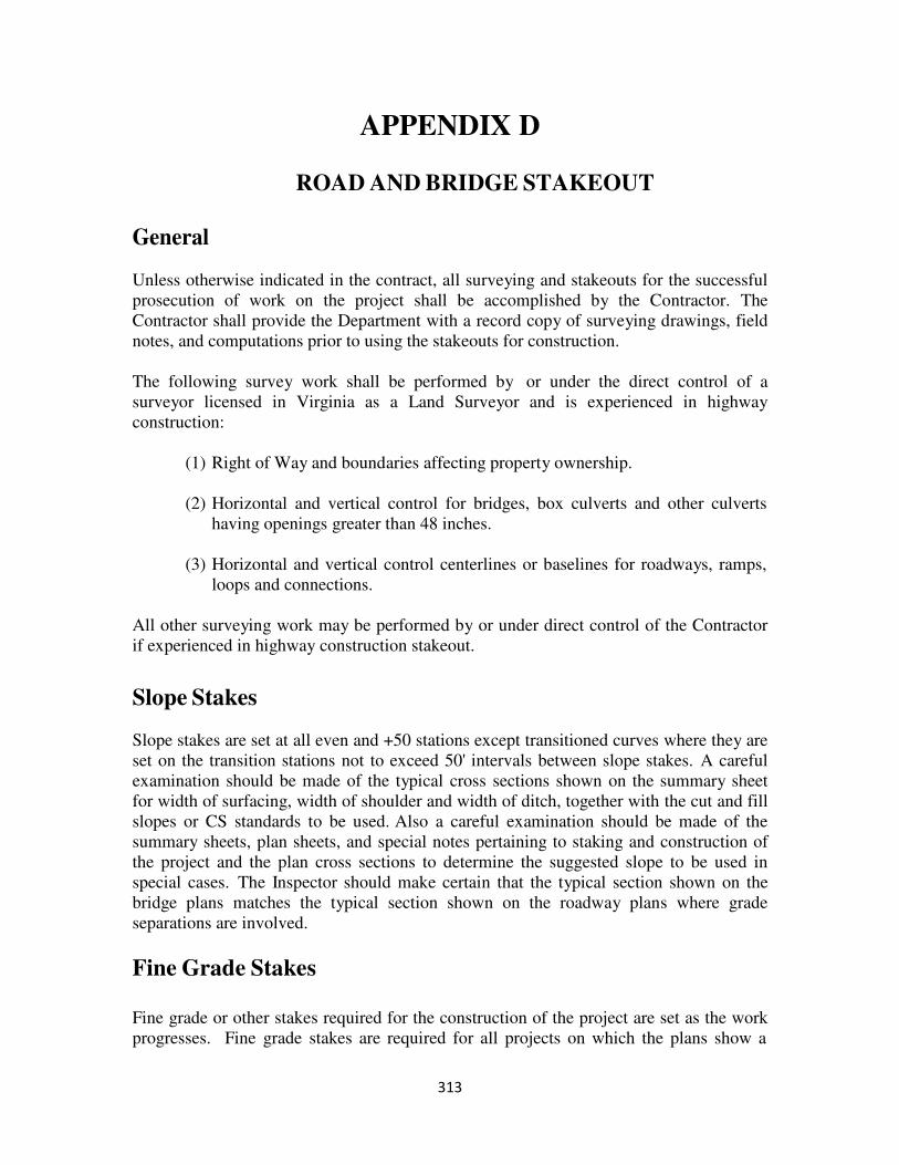
313
APPENDIX D
ROAD AND BRIDGE STAKEOUT
General
Unless otherwise indicated in the contract, all surveying and stakeouts for the successful
prosecution of work on the project shall be accomplished by the Contractor. The
Contractor shall provide the Department with a record copy of surveying drawings, field
notes, and computations prior to using the stakeouts for construction.
The following survey work shall be performed by or under the direct control of a
surveyor licensed in Virginia as a Land Surveyor and is experienced in highway
construction:
(1) Right of Way and boundaries affecting property ownership.
(2) Horizontal and vertical control for bridges, box culverts and other culverts
having openings greater than 48 inches.
(3) Horizontal and vertical control centerlines or baselines for roadways, ramps,
loops and connections.
All other surveying work may be performed by or under direct control of the Contractor
if experienced in highway construction stakeout.
Slope Stakes
Slope stakes are set at all even and +50 stations except transitioned curves where they are
set on the transition stations not to exceed 50' intervals between slope stakes. A careful
examination should be made of the typical cross sections shown on the summary sheet
for width of surfacing, width of shoulder and width of ditch, together with the cut and fill
slopes or CS standards to be used. Also a careful examination should be made of the
summary sheets, plan sheets, and special notes pertaining to staking and construction of
the project and the plan cross sections to determine the suggested slope to be used in
special cases. The Inspector should make certain that the typical section shown on the
bridge plans matches the typical section shown on the roadway plans where grade
separations are involved.
Fine Grade Stakes
Fine grade or other stakes required for the construction of the project are set as the work
progresses. Fine grade stakes are required for all projects on which the plans show a
314
definite grade line or as directed by the Engineer. On tangents the fine grade hubs are set
on one side of the roadway with distances and grades referenced to the finished grade on
centerline. On curves, fine grade hubs are required on both sides with offsets and grades
referenced to the edge of pavement. The Contractor shall ensure survey notes are kept on
fine grade stakes. Fine grade stakes should not be placed until they are actually needed.
Bridge Stakeouts
The Contractor sets stakes on the base line of the bridge, where the centerline of all piers
and abutments intersect, on either side of the bridge base line, on the centerline of the
piers and face of abutments. At least 2 stakes are set on each side of the base line of the
bridge on the centerline of the pier or abutment so that if one stake is knocked out, there
will still be a stake left in place. The line that is staked for the base line of the bridge is
usually the line shown on the bridge plans from which all dimensions are referenced.
This may not necessarily be the actual centerline of the bridge, or the centerline of the
roadway. The same is true of the piers and abutments. The pier or abutment centerline
staked may not be the actual centerline of the piers or abutments, but will be that line
shown on the bridge plans from which the dimensions are referenced.
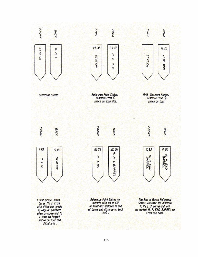
315
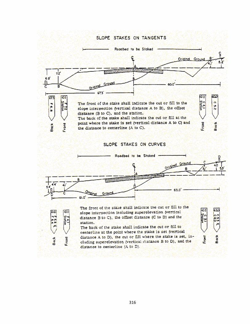
316
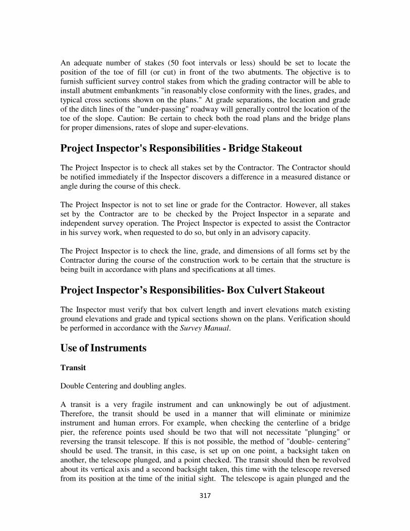
317
An adequate number of stakes (50 foot intervals or less) should be set to locate the
position of the toe of fill (or cut) in front of the two abutments. The objective is to
furnish sufficient survey control stakes from which the grading contractor will be able to
install abutment embankments "in reasonably close conformity with the lines, grades, and
typical cross sections shown on the plans." At grade separations, the location and grade
of the ditch lines of the "under-passing" roadway will generally control the location of the
toe of the slope. Caution: Be certain to check both the road plans and the bridge plans
for proper dimensions, rates of slope and super-elevations.
Project Inspector's Responsibilities - Bridge Stakeout
The Project Inspector is to check all stakes set by the Contractor. The Contractor should
be notified immediately if the Inspector discovers a difference in a measured distance or
angle during the course of this check.
The Project Inspector is not to set line or grade for the Contractor. However, all stakes
set by the Contractor are to be checked by the Project Inspector in a separate and
independent survey operation. The Project Inspector is expected to assist the Contractor
in his survey work, when requested to do so, but only in an advisory capacity.
The Project Inspector is to check the line, grade, and dimensions of all forms set by the
Contractor during the course of the construction work to be certain that the structure is
being built in accordance with plans and specifications at all times.
Project Inspector’s Responsibilities- Box Culvert Stakeout
The Inspector must verify that box culvert length and invert elevations match existing
ground elevations and grade and typical sections shown on the plans. Verification should
be performed in accordance with the Survey Manual.
Use of Instruments
Transit
Double Centering and doubling angles.
A transit is a very fragile instrument and can unknowingly be out of adjustment.
Therefore, the transit should be used in a manner that will eliminate or minimize
instrument and human errors. For example, when checking the centerline of a bridge
pier, the reference points used should be two that will not necessitate "plunging" or
reversing the transit telescope. If this is not possible, the method of "double- centering"
should be used. The transit, in this case, is set up on one point, a backsight taken on
another, the telescope plunged, and a point checked. The transit should then be revolved
about its vertical axis and a second backsight taken, this time with the telescope reversed
from its position at the time of the initial sight. The telescope is again plunged and the
318
point re-checked. Midway between the first point check and the second point check will
be the true prolongation of a line between the reference point sighted on and the reference
point on which the transit is set up.
Whenever it is required to turn an angle with a transit, it should also be turned using a
procedure that will minimize errors, especially human errors. After the initial angle has
been turned, the vernier setting should be left unaltered, the instrument turned on its
lower motion and a second sight taken. The upper clamp is loosened and the angle
turned a second time. The angle now has been doubled. In this way the process is
continued for as many times as desired. The vernier reading divided by the number of
times the angle was turned will give the correct angle.
All sights taken with a transit should be taken at the intersection of the center horizontal
and vertical cross hairs. The transit should be carefully focused on each sight to
minimize parallax. This can be checked by sighting through the telescope and moving
the eye from side to side. If the cross hairs remain stationary on an object while the eye
is being moved, parallax has been corrected.
Levels
Precautions need to be taken while using the level.
The Inspector should set up the tripod in a firm position and assure that it remains like
that.
The Inspector should level the instrument before reading and recording each sight and
check to see that it remains level periodically as it is being used. A level that is out of
adjustment will not be level at all points with a 360 degree arc.
Keep leveling screws firm but not excessively tight.
Keep the backsight and foresight distances as near equal as practical. If the instrument is
slightly out of adjustment, this procedure will tend to balance or minimize the error.
If possible, run levels, particularly when long sights are required, when temperatures are
not excessive. Heat waves often cause errors in reading the level rod.
Be careful to read the correct even foot and the correct tenth of a foot. These are very
common errors.
Avoid the use of un-stationary objects when setting temporary bench marks.
A bench mark (B.M.), either permanent or temporary, is established for elevation control.
Bench marks should be verified by running check levels from the succeeding or
preceding bench mark as shown on the road plans to the bench mark at the bridge site and
then back to the original bench mark.
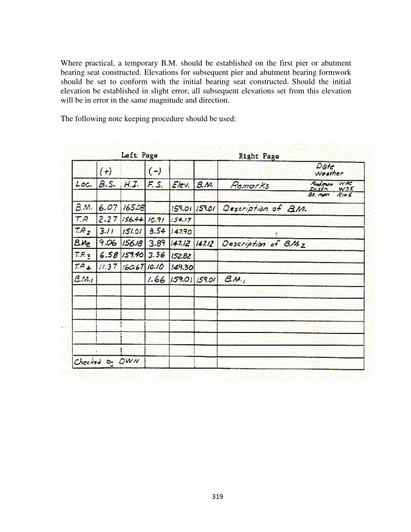
319
Where practical, a temporary B.M. should be established on the first pier or abutment
bearing seat constructed. Elevations for subsequent pier and abutment bearing formwork
should be set to conform with the initial bearing seat constructed. Should the initial
elevation be established in slight error, all subsequent elevations set from this elevation
will be in error in the same magnitude and direction.
The following note keeping procedure should be used:
320
Chaining
The act of measuring distances for survey work is known as chaining. The chain is a
steel tape which comes in 50, 100, 200, and 300 foot lengths. Chaining is usually done in
the horizontal position with the use of a hand lock level and plumb bobs. Non-horizontal
chaining (slope chaining) is employed only when the deviation angle from the horizontal
plane can be determined. The true horizontal distance is determined by using the
following trigonometric correction formula:
True Horizontal Length = (Slope Length) x (Cosine of Angle)
The following are common errors in chaining distances:
1. Chain not held horizontal - Both ends of the chain should be nearly level but it should
be remembered that a 100 foot chain out of level by 1.42 feet will result in an error of
0.01 foot.
2. Variations in temperature - A 100 foot steel chain expands and contracts about 0.01
foot for every 15o
F change in temperature. Generally, a chain is standard or 100 feet
long at 68o
F. For example, if a distance of exactly 100 feet is to be laid off when the
temperature is 98o
F (30o
F higher than standard), the distance actually used on the
chain should be 99.98 feet since the chain is 0.02 feet too long due to the temperature
change of +30o
F.
3. Variations in tension - In a 100 foot steel chain, a change in tension or pull of 3
pounds changes the length of a fully supported chain by 0.001-foot. Care should be
taken to exert enough tension to take out any undue sag - usually 15 to 30 pounds of
tension.
4. Chain not calibrated to its true length - The chain should be calibrated between two
known distance points to determine its true length and proper tension pull.
5. Reading numbers incorrectly, such as a "6" for a "9" - This error can be eliminated by
reading the numbers to either side of the one indicating the desired measurement.
Checking Plan Dimensions and Elevations
A thorough review of the designer's plans by both the Contractor's Representative and the
Inspector should precede the first construction operation. This review should accomplish
two important objectives:
1. Familiarization with plan details.
2. Dimension and elevation check for clarity and relative correctness.
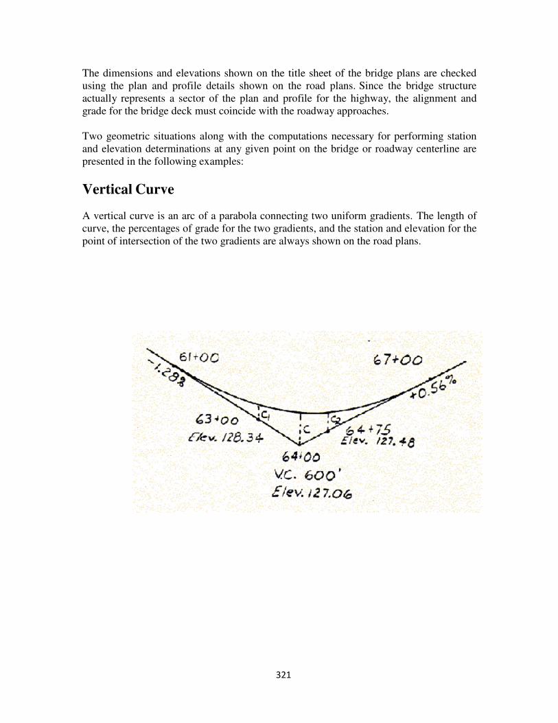
321
The dimensions and elevations shown on the title sheet of the bridge plans are checked
using the plan and profile details shown on the road plans. Since the bridge structure
actually represents a sector of the plan and profile for the highway, the alignment and
grade for the bridge deck must coincide with the roadway approaches.
Two geometric situations along with the computations necessary for performing station
and elevation determinations at any given point on the bridge or roadway centerline are
presented in the following examples:
Vertical Curve
A vertical curve is an arc of a parabola connecting two uniform gradients. The length of
curve, the percentages of grade for the two gradients, and the station and elevation for the
point of intersection of the two gradients are always shown on the road plans.
322
Compute the elevations on the tangents for all stations required:
Station 64+00 Station 64+75
Station 63+00 Station 64+00
1+00 = 100 feet 0+75 = 75 feet
Change in elevation:
1.28% x 100 feet = 1.28 feet
100
0.56% x 75 feet = 0.42 feet
100
Therefore, tangent elevations at station
Station 63+00 = 127.06+1.28 = 128.34 feet
Station 64+75 = 127.06+0.42 = 127.48 feet
2. Compute the center offset "c"
c = length of curve in stations x (Algebraic difference in grades)
8
c = 6/8 (1.28+0.56) = 1.38 feet
3. Compute intermediate offsets "c"1, "c"2 . . . etc.
(Dist. from closest end of vertical curve)
2
c1, c2.., = c x (half the length of vertical curve)2
c1 = 1.38 (200)2
= 0.61 feet c2 = 1.38 (225)2
= 0.78 feet
(300)2
(300)2
4. Apply the intermediate offset to the elevation of the tangent to obtain the required
elevation on the vertical curve.
Elevation on vertical curve at station 63+00 = 128.34+0.61 = 128.95 feet
Elevation on vertical curve at station 64+75 = 127.48+0.78 = 128.26 feet
323
5. Compute the station of highest or lowest point on the vertical curve:
Distance from beginning of curve =
(First gradient)x(length of vertical curve) =
Algebraic difference in grades
(1.28) x (600) = 768.00 = 417.39 feet
(1.28 + 0.56) 1.84
Therefore: Station (61+00) + (4+17.39) = (65+17.39)
6. Compute the elevation for the highest or lowest point on the curve:
Use steps (1), (3) and (4) above.
Answer: 128.23 feet
Circular Curves
The stationing of a centerline progresses around a curve in the same manner as along a
tangent. The point where a curve begins is called the P.C. (point of curvature) and where
it ends is called the P.T. (point of tangency). The point where the two tangents intersect
is called the P.I. (point of intersection).
The distance between two stations on a curve is 100 feet along the arc and somewhat less
along the chord. Therefore, the correct chord length must be measured that will result in
obtaining a distance equal to 100 feet around the arc. For curves having long radius
(2000 feet to infinity), the distance along the arc will be very nearly the same as along the
chord. However, for curves having a short radius (less than 2000 feet), the chord length
must be corrected. The correct chord length to be used can be found in Table V of a
Standard Field Book or by using the formula:
Chord Length = 2 Radius x Sine of deflection angle.
Curves are staked out using a transit and steel tape or "chain" by either of two methods:
1. By turning deflection angles (with the transit set up at the P.C.) from the tangent to
the station desired along the curve. The deflection angle can be computed by either
of the following formulas:
Deflection angles in degrees =
(Degree of Curve) x (Dist. from P.C. to P.O.C.)
200
324
Deflection angle in minutes =
0.3 (Degree of Curve) x (Dist. from P.C. to P.O.C.)
2. By turning deflection angles with the transit set-up at some known point on the curve.
The deflection angle is turned from the local tangent to the curve at the point of set-up
to any desired point on the curve. The transit can be oriented so that it will read zero
on the local tangent to the curve by the following procedure: Back sight at any
station on the curve with the vernier set at the difference between the deflection angle
of the station sighted on and the deflection angle of the station occupied and set in the
same direction as the direction of the curve. When the transit is turned to zero on the
vernier, it is oriented to the local tangent to the curve. The deflection angle of each
succeeding point on the curve can then be turned by using one of the formulas in step
one, except that the distance used is the distance from the set-up point to the point for
which the deflection is needed.
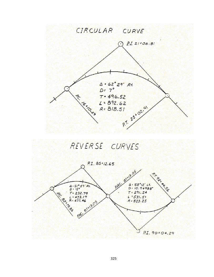
325
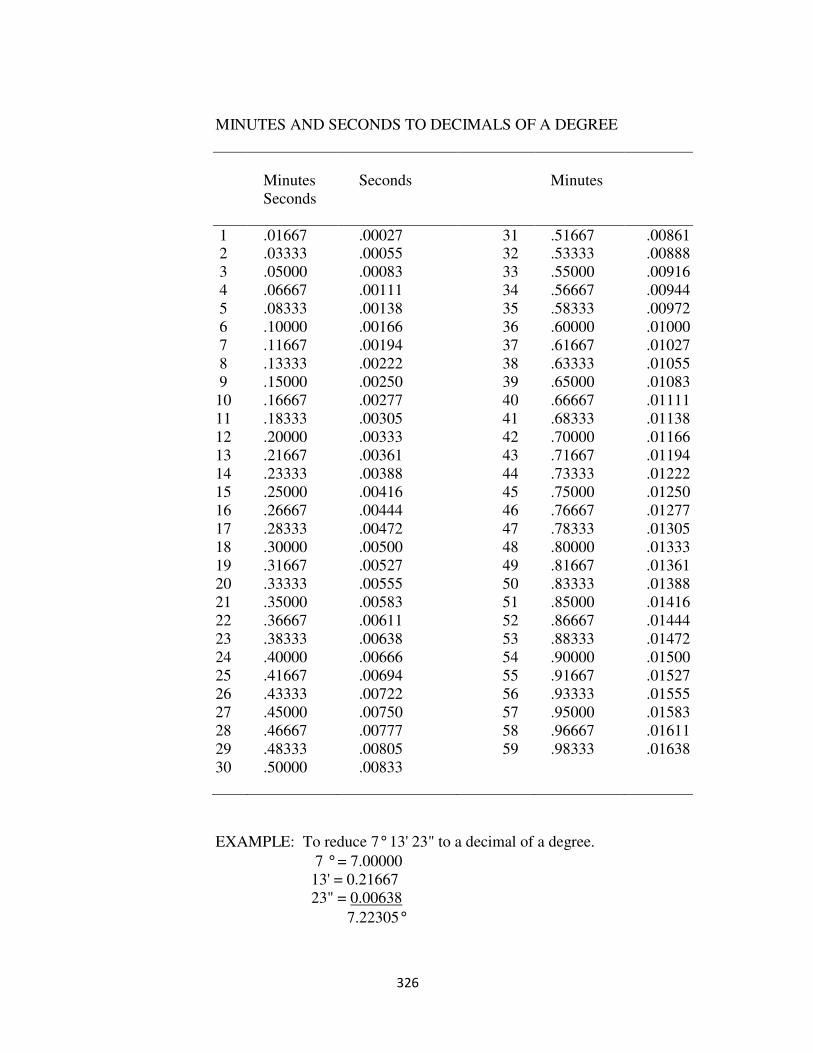
326
MINUTES AND SECONDS TO DECIMALS OF A DEGREE
Minutes
Seconds
Seconds
Minutes
1 .01667 .00027 31 .51667 .00861 2 .03333 .00055 32 .53333 .00888
3 .05000 .00083 33 .55000 .00916
4 .06667 .00111 34 .56667 .00944
5 .08333 .00138 35 .58333 .00972
6 .10000 .00166 36 .60000 .01000
7 .11667 .00194 37 .61667 .01027
8 .13333 .00222 38 .63333 .01055
9 .15000 .00250 39 .65000 .01083
10 .16667 .00277 40 .66667 .01111
11 .18333 .00305 41 .68333 .01138
12 .20000 .00333 42 .70000 .01166
13 .21667 .00361 43 .71667 .01194
14 .23333 .00388 44 .73333 .01222
15 .25000 .00416 45 .75000 .01250
16 .26667 .00444 46 .76667 .01277
17 .28333 .00472 47 .78333 .01305
18 .30000 .00500 48 .80000 .01333
19 .31667 .00527 49 .81667 .01361
20 .33333 .00555 50 .83333 .01388
21 .35000 .00583 51 .85000 .01416
22 .36667 .00611 52 .86667 .01444
23 .38333 .00638 53 .88333 .01472
24 .40000 .00666 54 .90000 .01500
25 .41667 .00694 55 .91667 .01527
26 .43333 .00722 56 .93333 .01555
27 .45000 .00750 57 .95000 .01583
28 .46667 .00777 58 .96667 .01611
29 .48333 .00805 59 .98333 .01638
30 .50000 .00833
EXAMPLE: To reduce 7° 13' 23" to a decimal of a degree.
7 ° = 7.00000
13' = 0.21667
23" = 0.00638
7.22305°

327
EXAMPLE: To reduce 8.32139 to degrees, minutes and seconds.
8.32139
-8.00000 = 8° 0.32139
-0.31667 = 19'
0.00472 = 17"8° 19' 17"
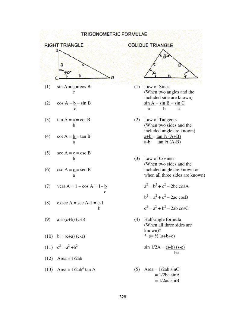
328
(1) sin A = a = cos B
c
(2) cos A = b = sin B
c
(3) tan A = a = cot B
b
(4) cot A = b = tan B
a
(5) sec A = c = csc B
b
(6) csc A = c = sec B
a
(7) vers A = 1 – cos A = 1– b
c
(1) Law of Sines (When two angles and the
included side are known)
sin A = sin B = sin C
a b c
(2) Law of Tangents
(When two sides and the
included angle are known)
a+b = tan ½ (A+B)
a-b tan ½ (A-B)
(3) Law of Cosines
(When two sides and the
included angle are known or
when all three sides are known)
a2
= b2
+ c2
– 2bc cosA
b2
= a2
+ c2
– 2ac cosB
(8) exsec A = sec A-1 = c-1
b
(9) a = (c+b) (c-b)
(10) b = (c+a) (c-a)
(11) c2
= a2
+b2
(12) Area = 1/2ab
(13) Area = 1/2ab2
tan A
c2
= a2
+ b2
– 2ab cosC
(4) Half-angle formula
(When all three sides are
known)*
* s= ½ (a+b+c)
sin 1/2A = (s-b) (s-c)
bc
(5) Area = 1/2ab sinC
= 1/2bc sinA
= 1/2ac sinB
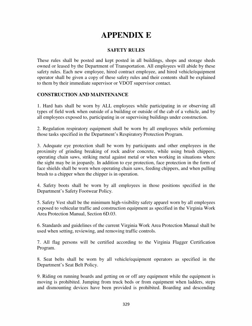
329
APPENDIX E
SAFETY RULES
These rules shall be posted and kept posted in all buildings, shops and storage sheds
owned or leased by the Department of Transportation. All employees will abide by these
safety rules. Each new employee, hired contract employee, and hired vehicle/equipment
operator shall be given a copy of these safety rules and their contents shall be explained
to them by their immediate supervisor or VDOT supervisor contact.
CONSTRUCTION AND MAINTENANCE
1. Hard hats shall be worn by ALL employees while participating in or observing all
types of field work when outside of a building or outside of the cab of a vehicle, and by
all employees exposed to, participating in or supervising buildings under construction.
2. Regulation respiratory equipment shall be worn by all employees while performing
those tasks specified in the Department’s Respiratory Protection Program.
3. Adequate eye protection shall be worn by participants and other employees in the
proximity of grinding breaking of rock and/or concrete, while using brush chippers,
operating chain saws, striking metal against metal or when working in situations where
the sight may be in jeopardy. In addition to eye protection, face protection in the form of
face shields shall be worn when operating chain saws, feeding chippers, and when pulling
brush to a chipper when the chipper is in operation.
4. Safety boots shall be worn by all employees in those positions specified in the
Department’s Safety Footwear Policy.
5. Safety Vest shall be the minimum high-visibility safety apparel worn by all employees
exposed to vehicular traffic and construction equipment as specified in the Virginia Work
Area Protection Manual, Section 6D.03.
6. Standards and guidelines of the current Virginia Work Area Protection Manual shall be
used when setting, reviewing, and removing traffic controls.
7. All flag persons will be certified according to the Virginia Flagger Certification
Program.
8. Seat belts shall be worn by all vehicle/equipment operators as specified in the
Department’s Seat Belt Policy.
9. Riding on running boards and getting on or off any equipment while the equipment is
moving is prohibited. Jumping from truck beds or from equipment when ladders, steps
and dismounting devices have been provided is prohibited. Boarding and descending

330
from equipment shall be done by facing the equipment and by maintaining three-point
contact.
10. Vehicles used to transport employees shall have seats firmly secured and adequate for
the number of employees to be carried. Under no circumstances shall more employees be
transported than can be safely seated. Employees who are in the process of training
another employee may, in controlled circumstances, ride for short distances with the
permission of supervisory personnel.
11. Only state employees and persons on official state business are allowed to be
transported in state vehicles.
12. No person shall be permitted to position themselves under any raised load or between
hinge points of equipment without first taking steps to support the load by the placing of
a safety bar or blocking.
13. Explosives shall be purchased, transported, stored, used, and disposed of by a
Virginia State Certified Blaster in possession of a current criminal history record check
and a commercial driver’s license with hazardous materials endorsement and a valid
physician’s certificate. All federal, state, and local regulations pertaining to explosives
must be strictly followed.
14. All electrical tools shall be adequately grounded or double insulated. GFCI protection
must be installed in accordance with the National Electrical Code (NEC) and current
Virginia Occupational Safety and Health (VOSH) regulations of the Department of Labor
and Industry (DLI). If extension cords are used, they shall be free of defects and designed
for their environment and intended use.
15. Before any employee performs any servicing, maintenance, repairs on any machinery
or equipment where the unexpected energizing startup or release of any type of energy
could occur and cause injury, the machinery or equipment will be rendered safe to work
on either being locked or tagged out. VDOT’s policy entitled “Policy for the Control of
Hazardous Energy Sources and Electrical Hazards-Lockout and Tagout” will be strictly
followed.
16. Only authorized persons in accordance with the VDOT policy entitled “Policy for the
Control of Hazardous Energy Sources and Electrical Hazards- Lockout and Tagout” are
permitted to do service, maintenance, or repairs on machinery and equipment.
17. No person shall enter a confined space without training, permits and authorization.
18. All new equipment operators are to be examined in accordance with the Asset
Management Division’s policy (Equipment Section Procedures 3.20- “Authorization to
Operate Equipment and Licensure Requirements”). Employees shall be properly
instructed in the safety regulations necessary for the safe and efficient operations of
equipment and the proper maintenance thereof.
331
GENERAL
19. Report all personal injuries and equipment accidents to your supervisor immediately.
20. A five-minute safety meeting will be held each morning before the work party
departs.
21. Any action such as horseplay on work operations will not be tolerated.
22. In order to promote safer working conditions, good housekeeping will be maintained
in all our facilities and work sites.
23. Smoking is prohibited inside all offices, buildings and inside equipment and any
vehicles owned or paid for by the state. This includes tractors and backhoes, as well as
vehicles that are leased or rented with state funds. The Governor’s Executive Order # 41
(2006) on smoking will be in effect.
24. Smoking or the use of a torch, lantern, spark producing device, etc., or any open
flame within 50 feet of gasoline or other flammable liquids, is prohibited.
25. Transporting any type of empty, filled or partially filled flammable containers or
explosives in the passenger compartment of any vehicle/equipment carrying employees is
prohibited.
26. Open fires must not be built within 200 feet of any point where bituminous,
flammable or hazardous materials are stored or are being transferred.
27. No open flame shall be used to inspect or examine drums, tank cars or other
containers in which bituminous, flammable, or hazardous materials have been stored.
28. The use of gasoline to start a fire or as a cleaning agent is prohibited.
29. Under no circumstances shall equipment motors or engines be operated or started
when fuel leaks are present.
30. When welding or assisting in this operation, employees shall use regulation hoods.
When cutting or burning metals, approved eye protection shall be used. Welding on
tanks, distributors or any other container of bituminous or flammable materials used for
transporting or storage shall not be done unless the proper safeguards are taken. All
bituminous or flammable material tanks are to have wide open vents while work is being
done. Before welding, the container is to be steamed, flushed and ventilated for 48 hours
to remove all fumes. Tanks will be checked with explosive meter before welding is
performed.
332
31. Asphalt kettle burners shall be lighted or re-lighted in accordance with the
manufacturer's Instructions and shall be operated per the manufactures’ instructions for
operation and safety.
32. Undermining a soil, sand or gravel pit, a soil, shale or gravel bank, or any other
excavation, is prohibited. The provisions of Virginia Occupational Safety & Health
regulation (VOSH) ‘Excavation Standard, Construction Industry’ (16 VAC 25-170-10 et
seq.) shall be strictly followed.
33. No employee shall enter waters without wearing an approved water safety device,
e.g., U.S. Coast Guard approved life jackets or buoyant work vests. This instruction
remains in effect even if a boat is used in the water negotiation process.
34. Fall protection is required:
• When an employee is exposed working at elevated heights of six feet (6) or
greater when engaged in construction related activities.
• When doing non-construction related activities at VDOT facilities, fall protection
is required when an employee is exposed to heights of four feet (4) or greater.
Such fall protection will comply with Virginia Occupational Safety & Health
(VOSH) General Industry regulation (1910 Subpart D) “Walking-Working
Surfaces.”
• When working from the basket of aerial lifts, an employee shall wear a personal
fall arrest system (PFAS) with an attached lanyard connected to an approved
manufacturer’s anchorage point on the equipment. Employees shall not work in
the baskets of aerial lifts such as bucket trucks, platform trucks, and other
equipment when over the top of moving traffic.
35. All backing incidents are preventable. The same attention and awareness required
to operate a vehicle in the forward direction must be used when backing a vehicle. Where
there is limited sight distance, obstructions, or limited maneuverability, a ground guide or
spotter must be used, if available. If a spotter or ground guide is not available, have a
G.O.A.L – Get Out And Look to avoid a backing incident. When parking a vehicle, pull
through parking is preferred or parking in a safe and legal location free of obstructions to
avoid backing altogether. In addition, back-in parking of state vehicles should be
practiced at all times, unless situations do not allow.