
VDM Alloy 718 CTP Nicrofer 5219 Nb · September 2017 VDM® Alloy 718 CTP 2 VDM® Alloy 718 CTP is...
13
VDM ® Alloy 718 CTP Nicrofer 5219 Nb Material Data Sheet No. 4127 September 2017
Transcript of VDM Alloy 718 CTP Nicrofer 5219 Nb · September 2017 VDM® Alloy 718 CTP 2 VDM® Alloy 718 CTP is...

VDMreg Alloy 718 CTP
Nicrofer 5219 Nb
Material Data Sheet No 4127
September 2017
September 2017 VDMreg Alloy 718 CTP
2
VDMreg Alloy 718 CTP is an age-hardenable nickel-chromium-iron-molybdenum alloy The age hardening is achieved by
specific additions of niobium titanium and aluminum It can be delivered in the solution-annealed or in different age-
hardened conditions The standard Alloy 718 CTP version has a minimum yield strength of 120 ksi and can be ordered
with the material designation 120K A further variant of Alloy 718 CTP has a minimum yield strength of 150 ksi and can
be ordered with the material designation 150K
VDMreg Alloy 718 CTP is characterized by
Good processing properties in the solution-annealed condition
Good mechanical short and long-term properties and excellent fatigue strength in the age-hardened condition
Excellent mechanical properties in low temperatures
Excellent resistance to stress corrosion cracking and pitting in chloride-containing media
Excellent resistance to stress corrosion cracking and sulfide stress cracking in sour (H2S-containing) oilfield
environments
Depending on the use conditions narrower analysis limits apply to certain alloy elements This is true in particular for
carbon and niobium but to lesser extent also for aluminum and titanium The purpose of this limitation is to optimize the
structure and mechanical properties with regard to the intended use VDMreg Alloy 718 CTP is characterized by limited
levels of carbon and niobium
Additional information can be found in the material data sheet of the VDMreg Alloy 718
Designations
Standard Material designation
EN 24668 - NiCr19Fe19Nb5Mo3
ISO NiCr19Nb5Mo3
UNS N07718
AFNOR NC19FeNb
BS NA 51
Table 1a ndash Designations
Standards
Product form DIN DIN EN ISO ASTM NACE Others
Rod bar
MR 0175 ISO 15156 API 6ACRA
Sheet plate 17750
B 670
Strip 17744
17750
10302 6208 B 670
Wire 17744
17753
Ballot for inclusion of the 150K variant of Alloy 718 CTP in NACE MR 0175ISO15156 and API6ACRA is pending
Table 1b ndash Standards
VDMreg Alloy 718 CTP
Nicrofer 5219 Nb
September 2017 VDMreg Alloy 718 CTP
3
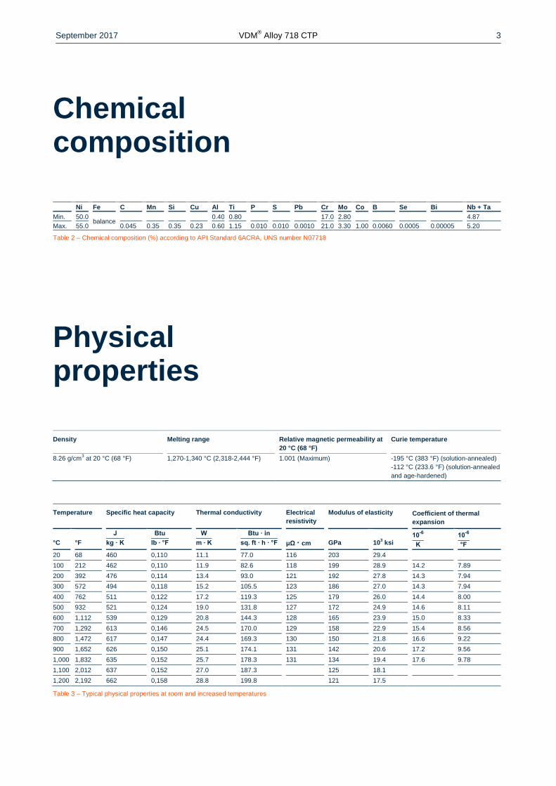
Chemical composition
Ni Fe C Mn Si Cu Al Ti P S Pb Cr Mo Co B Se Bi Nb + Ta
Min 500 balance
040 080 170 280 487
Max 550 0045 035 035 023 060 115 0010 0010 00010 210 330 100 00060 00005 000005 520
Table 2 ndash Chemical composition () according to API Standard 6ACRA UNS number N07718
Physical properties
Density Melting range Relative magnetic permeability at
20 degC (68 degF)
Curie temperature
826 gcm3 at 20 degC (68 degF) 1270-1340 degC (2318-2444 degF) 1001 (Maximum) -195 degC (383 degF) (solution-annealed)
-112 degC (2336 degF) (solution-annealed
and age-hardened)
Temperature Specific heat capacity Thermal conductivity Electrical
resistivity
Modulus of elasticity Coefficient of thermal
expansion
degC
degF
J
kg middot K
Btu
lb ∙ degF
W
m ∙ K
Btu ∙ in
sq ft ∙ h ∙ degF
μΩ middot cm
GPa
103 ksi
10-6
K
10-6
degF
20 68 460 0110 111 770 116 203 294
100 212 462 0110 119 826 118 199 289 142 789
200 392 476 0114 134 930 121 192 278 143 794
300 572 494 0118 152 1055 123 186 270 143 794
400 762 511 0122 172 1193 125 179 260 144 800
500 932 521 0124 190 1318 127 172 249 146 811
600 1112 539 0129 208 1443 128 165 239 150 833
700 1292 613 0146 245 1700 129 158 229 154 856
800 1472 617 0147 244 1693 130 150 218 166 922
900 1652 626 0150 251 1741 131 142 206 172 956
1000 1832 635 0152 257 1783 131 134 194 176 978
1100 2012 637 0152 270 1873 125 181
1200 2192 662 0158 288 1998 121 175
Table 3 ndash Typical physical properties at room and increased temperatures
September 2017 VDMreg Alloy 718 CTP
4
Microstructural properties
VDMreg Alloy 718 CTP has an austenitic microstructure with multiple phases By means of different heat treatments
graduated mechanical properties of the material can be reached The excellent mechanical properties of VDMreg Alloy
718 CTP result from the γlsquolsquo-formation during the precipitation hardening Depending on the precipitation hardening tem-
perature the size of the γlsquolsquo-particles vary which leads to different strength properties More information can be found in
the ldquoHeat treatmentrdquo chapter
Mechanical properties
The following mechanical properties of VDMreg Alloy 718 CTP apply to hot or cold-formed material in the age-hardened
condition in the specified dimensions Material with specified properties outside of the listed dimensions ranges (see
ldquoAvailabilityrdquo chapter) must be requested separately
Material
designation
Temperature Yield strength
Rp 02
Tensile strength
Rm
Elongation
A
Reduction of area
Z
degC degF MPa ksi MPa ksi
120K -196 -3208 1138 1651 1606 2339 28 34
-100 -148 1049 1521 1400 2031 27 45
20 68 962 1395 1256 1822 29 43
100 212 931 1350 1231 1785 26 38
150 302 913 1324 1211 1756 24 42
200 392 901 1307 1196 1735 235 38
150K 175 347 1040 1509 1237 1795 21 40
205 401 1039 1506 1237 1794 22 39
Table 4 ndash Typical mechanical properties of age-hardened VDMreg Alloy 718 CTP material designations 120K and 150K
Material
designation
Product form Dimensions
Yield strength
Rp 02
Tensile strength
Rm
Elongation
A
Reduction of area
Z
mm in MPa ksi MPa ksi
120K Round bar le 254 le 10 827-1000 120-145 ge 1034 ge 150 ge 20 ge 35
Round bar ge 254 ge 10 827-1000 120-145 ge 1034 ge 150 ge 20 ge 25
150K Round bar le 254 le 10 ge 1034 ge 150 ge 1241 ge 180 ge 20 ge 35
Round bar ge 254 ge 10 ge 1034 ge 150 ge 1241 ge 180 ge 20 ge 25
Table 5 ndash Mechanical properties at ambient temperature of age-hardened VDMreg Alloy 718 CTP material designations 120K and 150K
September 2017 VDMreg Alloy 718 CTP
5
Charpy V-notch impact toughness
Material Designation QTC Cross Section Thickness Orientation Minimum Average Minimum Single Lateral Expansion
mm in J ftlbs J ftlbs mm in
120K lt 76 lt 3 Longitudinal 68 50 61 45 038 0015
ge 76-254 ge 3-10 Transverse 47 35 41 30 038 0015
gt 254 gt 10 Transverse 41 30 37 27 038 0015
150K lt 76 lt 3 Longitudinal 68 50 61 45 038 0015
ge 76-254 ge 3-10 Transverse 47 35 41 30 038 0015
gt 254 gt 10 Transverse 41 30 37 27 038 0015
Table 6 ndash Impact testing shall be performed on a set of three specimens and all tests at or below -60 degC (-75 degF)
Hardness Rockwell HRC Material Designation Hardness
HRC
min max
120K 32 40
150K 32 45
Table 7 ndash Hardness according to NACE MR 0175ISO15156
September 2017 VDMreg Alloy 718 CTP
6
Corrosion resistance
As a result of the high chromium and molybdenum concentrations VDMreg Alloy 718 CTP has very good general corro-
sion resistance and pitting corrosion resistance in many environments By virtue of its high nickel content VDMreg Alloy
718 CTP also has good resistance against stress corrosion
Applications
Due to its excellent corrosion resistance and its good workability VDMreg Alloy 718 CTP is versatile in use in the oil and
gas industry in the offshore industry and in marine engineering The alloy has proven itself well especially for oilfield
completion equipment in very demanding environments containing H2S CO2 and high chlorides The alloy has also
proven itself for highly stressed oilfield components
September 2017 VDMreg Alloy 718 CTP
7
Fabrication and heat treatment
VDMreg Alloy 718 CTP can be easily processed by both hot and cold forming and can also be machined
Heating
It is important that the workpieces are clean and free of any contaminants before and during heat treatment Sulfur
phosphorus lead and other low-melting point metals can lead to damage when heat-treating VDMreg Alloy 718 CTP This
type of contamination is also contained in marking and temperature display paints or pens and also in lubricating
grease oils fuels and similar materials Fuels must have as low a sulfur content as possible Natural gas should contain
less than 01 by weight of sulfur Heating oil with a maximum sulfur content of 05 by weight is also suitable Electric
furnaces are to be preferred due to precise temperature control and lack of contaminants due to fuel The furnace tem-
perature should be set between neutral and slightly oxidizing and should not change between oxidizing and reducing
The workpieces must not come in direct contact with flames
Hot forming
VDMreg
Alloy 718 CTP can be hot-worked at a temperature range of between 1120 and 900 degC (2048 and 1652 degF) It
should be done evenly in order to receive a homogeneous microstructure The subsequent deformation should be at
least 20 and be implemented below 960 degC (1760 degF) to achieve an optimal toughness The cooling down should
preferably take place in water
Cold forming
The workpieces should be in the solution-annealed condition for cold working VDMreg
Alloy 718 CPT has a significantly
higher work hardening than austenitic stainless steels This must be taken into account during the design and selection
of forming tools and equipment and during the planning of forming processes Intermediate annealing is necessary for
major cold forming work To achieve a high strength a combination of cold forming with subsequent age hardening is an
option
Heat treatment
Various solution-annealing and aging conditions are combined in order to obtain the different required material proper-
ties Since the diffusion rate crucial for the formation of the γ-phase is relatively low long age hardening times are re-
quired to achieve the optimal mechanical quality values for VDMreg Alloy 718 CTP The material must be placed in a
furnace that has been heated up to the maximum annealing temperature before any heat treatment For strip products
the heat treatment can be performed in a continuous furnace at a speed and temperature that is adapted to the strip
thickness The cleanliness requirements listed under the Heating chapter must be observed
Heat treatment for VDMreg Alloy 718 CTP 120K reference API standard 6ACRA for use under H2S-containing media
Solution annealing 1-25 hours at 1021-1052 degC (1870-1925 degF) cooling down in water
Age hardening 6-8 hours at 774-802 degC (1425-1475 degF) cooling down in air or faster
Heat treatment for VDMreg Alloy 718 CTP 150K according to NACE MR0175ISO15156
Solution annealing 1-25 hours at 1021-1052 degC (1870-1925 degF) cooling down in water
Age hardening min 8 hours at 700-750 degC (1292-1382 degF) furnace cool to 600-650 degC (1112-1202 degF) and
hold for additional 8 hours minimum air cool
Ballot for inclusion of Alloy 718 CTP 150K is pending
Descaling and pickling
Oxides from VDMreg Alloy 718 CPT and discolorations in the area around welds have better bonding than in stainless
steels Grinding using extremely fine abrasive belts or grinding discs is recommended It is imperative that grinding
burns be avoided Before pickling in nitric-hydrofluoric acid mixtures the oxide layers should be removed by abrasive
September 2017 VDMreg Alloy 718 CTP
8
blasting or fine grinding or pre-treated in molten salts The pickling baths used should be carefully monitored with re-
gard to concentration and temperature
Machining
The mechanical processing of VDMreg Alloy 718 CTP should take place in a solution-annealed condition For reasons of
the increased tendency to work hardening in comparison with low-alloy austenitic stainless steels a lower cutting speed
should be selected and the cutting tool should stay engaged at all times An adequate chip depth is important in order to
cut below a previously formed work-hardened zone Optimum heat dissipation through the use of large quantities of
suitable preferably aqueous lubricants has considerable influence on a stable machining process Although the materi-
al in the solution-annealed condition is easier to process and the strain on tools is less better surface quality is achieved
in the age-hardened condition The best results in terms of the surface quality of the finished product are achieved
however by pre-treatment before age hardening and finishing after age hardening
Welding information
When welding nickel alloys and special stainless steels the following information should be taken into account
Workplace
A separate workplace should be provided which is clearly separated from the areas where carbon steel is processed
Maximum cleanliness is required and drafts should be avoided during gas-shielded welding
Auxiliary equipment and clothing
Clean fine leather gloves and clean working clothes must be used
Tools and machines
Tools that have been used for other materials may not be used for nickel alloys and stainless steels Only stainless steel
brushes may be used Processing and treatment machines such as shears punches or rollers must be fitted (felt card-
board films) so that the workpiece surfaces cannot be damaged by the pressing in of iron particles through such equip-
ment This can ultimately lead to corrosion
Edge preparation
Weld seam preparation should preferably be carried out using mechanical methods such as lathing milling or planing
Abrasive waterjet cutting or plasma cutting is also possible In the latter case however the cut edge (seam flank) must
be cleanly reworked Careful grinding without overheating is also permissible
Striking the arc
The arc should only be struck in the seam area such as on the weld edges or on an outlet piece and not on the com-
ponent surface Scaling areas are areas in which corrosion more easily occurs
September 2017 VDMreg Alloy 718 CTP
9
Figure 1 ndash Seam preparation for welding nickel alloys
and special stainless steels
Included angle
Compared to C-steels nickel alloys and special stainless steels exhibit lower heat conductivity and greater heat expan-
sion These properties must be taken into account by larger root openings or root gaps (1 to 3 mm 0039 to 0118 in)
Due to the viscosity of the welding material (compared to standard austenites) and the tendency to shrink opening an-
gles of 60 to 70deg ndash as shown in figure 1 ndash have to be provided for butt welds
Cleaning
Cleaning of the base material in the seam area (both sides) and the welding filler (eg welding rod) should be carried
out using acetone
Welding parameters and influences
It must be ensured that work is carried out using targeted heat application and low heat input The stringer bead tech-
nique is recommended The interpass temperature should not exceed 100 degC (212 degF) A continuous monitoring of the
welding parameters is in principle required
September 2017 VDMreg Alloy 718 CTP
10
Heat input Q can be calculated as follows
Q=U middot I middot 60
v middot 1000 (
kJ
cm)
U = arc voltage volts
I = welding current strength amperes
v = welding speed cmminute
Welding technique
VDMreg Alloy 718 CTP can be welded with a number of different welding processes Wherever metal inert gas welding
process is used impulse technology is preferable The material should be in its solution-annealed condition for welding
and should be free of scale grease and markings When welding the root and possibly the first filler beads care should
be taken to achieve best quality root protection (eg argon 46) so that the welding edge is free from oxides after weld-
ing the root Any temper colors must be removed preferably using a stainless steel brush while the welding seam is still
hot
Welding filler
The following welding consumable is recommended
VDMreg FM 718 W-no 24667
AWS A514 ERNiFeCr-2
ISO 18274
The use of bar electrodes in sleeves is possible
Post-treatment
During optimum implementation of the work brushing directly after welding in other words in a hot condition without
additional pickling results in the required surface condition ie discolorations can be removed completely Once the
welding work is finished age hardening can be conducted if desired (see the section ldquoHeat treatmentrdquo) Pickling if re-
quired or specified should generally be the last operation in the welding process The information contained in the sec-
tion entitled Descaling and pickling must be observed
September 2017 VDMreg Alloy 718 CTP
11
Thickness Welding
technique
Filler material Root pass1)
Intermediate
and final passes
Welding
speed
Shielding gas
(mm) Diameter
(mm)
Speed
(mmin)
I in (A) U in (V) I in (A) U in (V) (cmmin) Type Rate
(lmin)
3 manual TIG 20 - 90 10 110-120 11 15 I1 R1 mit
max 3 H2
8-10
6 manual TIG 20-24 - 100-110 10 120-140 12 14-16 I1 R1 mit
max 3 H2
8-10
8 manual TIG 24 - 100-110 11 130-140 12 14-16 I1 R1 mit
max 3 H2
8-10
10 manual TIG 24 - 100-110 11 130-140 12 14-16 I1 R1 mit
max 3 H2
8-10
3 autom TIG 2)
12 12 - - 150 11 25 I1 R1 mit
max 3 H2
12-14
5 autom TIG 2)
12 14 - - 180 12 25 I1 R1 mit
max 3 H2
12-14
2 autom TIG
HD2)
10 - - - 180 11 80 I1 R1 mit
max 3 H2
12-14
10 autom TIG
HD2)
12 - - - 220 12 40 I1 R1 mit
max 3 H2
12-14
4 Plasma3)
12 10 180 25 - - 30 I1 R1 mit
max 3 H2
30
6 Plasma3)
12 10 200-220 26 - - 26 I1 R1 mit
max 3 H2
30
1) It must be ensured that there is sufficient root protection for example using Ar 46 for all inert gas welding processes
2) The root pass should be welded manually (see manual TIG)
3) Recommended plasma gas Ar 46 rate 30 to 35 lmin
Section energy kJcm
autom TIG HD max 6 TIG GMAW manual automated max 8 Plasma max 10
Figures are for guidance only and are intended to facilitate setting of the welding machines
Table 7 - Welding parameters
September 2017 VDMreg Alloy 718 CTP
12
Availability
VDMreg Alloy 718 CTP is available in the following standard semi-finished forms
Rod and bar
Delivery condition Forged rolled drawn heat treated (solution-annealed or age-hardened) oxidized descaled or pick-
led turned peeled ground or polished
Dimensions Outside diameter
mm (in)
Length
mm (in)
General dimensions 6-800 (024-3150) 1500-12000 (5906-47244)
Material specific dimensions 10-350 (039-1378) 1500-12000 (5906-47244)
Sheet and plate
Delivery condition Hot or cold rolled heat-treated descaled or pickled
Condition Thickness
mm (in)
Width
mm (in)
Length
mm (in)
Piece weight
Kg (lb)
Cold rolled 11-7 (004-028) le 2000 (7874) le 5500 (21654) le 1100 (2425)
Hot rolled 3-8 (012-031) le 2500 (9843) le 5500 (21654) le 1100 (2425)
Hot rolled 8-50 (031-197) le 2500 (9843) le 8000 (31496) le 1100 (2425)
Sheets can be manufactured considering the minimum and maximum dimensions
2 mm (008 in) thickness on request
Strip
Delivery condition Cold rolled heat treated pickled or bright annealed
Thickness
mm (in)
Width
mm (in)
Coil - inside diameter
mm
0025-015
(0001-0006)
4-230
(016-906)
300 400 500 ndash
015-025
(0006-001)
4-720
(016-2834)
300 400 500 ndash
025-06
(001-0024)
6-750
(024-295)
ndash 400 500 600
06-1
(0024-004)
8-750
(032-295)
ndash 400 500 600
1-2
(004-008)
15-750
(06-295)
ndash 400 500 600
2-3
(008-012)
25-750
(098-295)
ndash 400 500 600
Rolled sheet ndash separated from the coil ndash are available in lengths from 250 to 4000 mm (984 to 15748 in)
Wire
Delivery condition Drawn bright frac14 hard to hard bright annealed in rings containers on spools and spiders
Drawn
mm (in)
Hot rolled
mm (in)
016-10 (0006-04) 55-19 (022-075)
Other shapes and dimensions available on request
September 2017 VDMreg Alloy 718 CTP
13
Legal notice
01 September 2017
Publisher
VDM Metals International GmbH
Plettenberger Straszlige 2
58791 Werdohl
Germany
Disclaimer
All information contained in this data sheet is based on the results of research and development work carried out by
VDM Metals International GmbH and the data contained in the specifications and standards listed available at the time
of printing The information does not represent a guarantee of specific properties VDM Metals reserves the right to
change information without notice All information contained in this data sheet is compiled to the best of our knowledge
and is provided without liability Deliveries and services are subject exclusively to the relevant contractual conditions and
the General Terms and Conditions issued by VDM Metals International GmbH Use of the most up-to-date version of
this data sheet is the responsibility of the customer
VDM Metals GmbH
Plettenberger Strasse 2
58791 Werdohl
Germany
Phone +49 (0)2392 55 0
Fax +49 (0)2392 55 22 17
vdmvdm-metalscom
wwwvdm-metalscom

September 2017 VDMreg Alloy 718 CTP
2
VDMreg Alloy 718 CTP is an age-hardenable nickel-chromium-iron-molybdenum alloy The age hardening is achieved by
specific additions of niobium titanium and aluminum It can be delivered in the solution-annealed or in different age-
hardened conditions The standard Alloy 718 CTP version has a minimum yield strength of 120 ksi and can be ordered
with the material designation 120K A further variant of Alloy 718 CTP has a minimum yield strength of 150 ksi and can
be ordered with the material designation 150K
VDMreg Alloy 718 CTP is characterized by
Good processing properties in the solution-annealed condition
Good mechanical short and long-term properties and excellent fatigue strength in the age-hardened condition
Excellent mechanical properties in low temperatures
Excellent resistance to stress corrosion cracking and pitting in chloride-containing media
Excellent resistance to stress corrosion cracking and sulfide stress cracking in sour (H2S-containing) oilfield
environments
Depending on the use conditions narrower analysis limits apply to certain alloy elements This is true in particular for
carbon and niobium but to lesser extent also for aluminum and titanium The purpose of this limitation is to optimize the
structure and mechanical properties with regard to the intended use VDMreg Alloy 718 CTP is characterized by limited
levels of carbon and niobium
Additional information can be found in the material data sheet of the VDMreg Alloy 718
Designations
Standard Material designation
EN 24668 - NiCr19Fe19Nb5Mo3
ISO NiCr19Nb5Mo3
UNS N07718
AFNOR NC19FeNb
BS NA 51
Table 1a ndash Designations
Standards
Product form DIN DIN EN ISO ASTM NACE Others
Rod bar
MR 0175 ISO 15156 API 6ACRA
Sheet plate 17750
B 670
Strip 17744
17750
10302 6208 B 670
Wire 17744
17753
Ballot for inclusion of the 150K variant of Alloy 718 CTP in NACE MR 0175ISO15156 and API6ACRA is pending
Table 1b ndash Standards
VDMreg Alloy 718 CTP
Nicrofer 5219 Nb
September 2017 VDMreg Alloy 718 CTP
3
Chemical composition
Ni Fe C Mn Si Cu Al Ti P S Pb Cr Mo Co B Se Bi Nb + Ta
Min 500 balance
040 080 170 280 487
Max 550 0045 035 035 023 060 115 0010 0010 00010 210 330 100 00060 00005 000005 520
Table 2 ndash Chemical composition () according to API Standard 6ACRA UNS number N07718
Physical properties
Density Melting range Relative magnetic permeability at
20 degC (68 degF)
Curie temperature
826 gcm3 at 20 degC (68 degF) 1270-1340 degC (2318-2444 degF) 1001 (Maximum) -195 degC (383 degF) (solution-annealed)
-112 degC (2336 degF) (solution-annealed
and age-hardened)
Temperature Specific heat capacity Thermal conductivity Electrical
resistivity
Modulus of elasticity Coefficient of thermal
expansion
degC
degF
J
kg middot K
Btu
lb ∙ degF
W
m ∙ K
Btu ∙ in
sq ft ∙ h ∙ degF
μΩ middot cm
GPa
103 ksi
10-6
K
10-6
degF
20 68 460 0110 111 770 116 203 294
100 212 462 0110 119 826 118 199 289 142 789
200 392 476 0114 134 930 121 192 278 143 794
300 572 494 0118 152 1055 123 186 270 143 794
400 762 511 0122 172 1193 125 179 260 144 800
500 932 521 0124 190 1318 127 172 249 146 811
600 1112 539 0129 208 1443 128 165 239 150 833
700 1292 613 0146 245 1700 129 158 229 154 856
800 1472 617 0147 244 1693 130 150 218 166 922
900 1652 626 0150 251 1741 131 142 206 172 956
1000 1832 635 0152 257 1783 131 134 194 176 978
1100 2012 637 0152 270 1873 125 181
1200 2192 662 0158 288 1998 121 175
Table 3 ndash Typical physical properties at room and increased temperatures
September 2017 VDMreg Alloy 718 CTP
4
Microstructural properties
VDMreg Alloy 718 CTP has an austenitic microstructure with multiple phases By means of different heat treatments
graduated mechanical properties of the material can be reached The excellent mechanical properties of VDMreg Alloy
718 CTP result from the γlsquolsquo-formation during the precipitation hardening Depending on the precipitation hardening tem-
perature the size of the γlsquolsquo-particles vary which leads to different strength properties More information can be found in
the ldquoHeat treatmentrdquo chapter
Mechanical properties
The following mechanical properties of VDMreg Alloy 718 CTP apply to hot or cold-formed material in the age-hardened
condition in the specified dimensions Material with specified properties outside of the listed dimensions ranges (see
ldquoAvailabilityrdquo chapter) must be requested separately
Material
designation
Temperature Yield strength
Rp 02
Tensile strength
Rm
Elongation
A
Reduction of area
Z
degC degF MPa ksi MPa ksi
120K -196 -3208 1138 1651 1606 2339 28 34
-100 -148 1049 1521 1400 2031 27 45
20 68 962 1395 1256 1822 29 43
100 212 931 1350 1231 1785 26 38
150 302 913 1324 1211 1756 24 42
200 392 901 1307 1196 1735 235 38
150K 175 347 1040 1509 1237 1795 21 40
205 401 1039 1506 1237 1794 22 39
Table 4 ndash Typical mechanical properties of age-hardened VDMreg Alloy 718 CTP material designations 120K and 150K
Material
designation
Product form Dimensions
Yield strength
Rp 02
Tensile strength
Rm
Elongation
A
Reduction of area
Z
mm in MPa ksi MPa ksi
120K Round bar le 254 le 10 827-1000 120-145 ge 1034 ge 150 ge 20 ge 35
Round bar ge 254 ge 10 827-1000 120-145 ge 1034 ge 150 ge 20 ge 25
150K Round bar le 254 le 10 ge 1034 ge 150 ge 1241 ge 180 ge 20 ge 35
Round bar ge 254 ge 10 ge 1034 ge 150 ge 1241 ge 180 ge 20 ge 25
Table 5 ndash Mechanical properties at ambient temperature of age-hardened VDMreg Alloy 718 CTP material designations 120K and 150K
September 2017 VDMreg Alloy 718 CTP
5
Charpy V-notch impact toughness
Material Designation QTC Cross Section Thickness Orientation Minimum Average Minimum Single Lateral Expansion
mm in J ftlbs J ftlbs mm in
120K lt 76 lt 3 Longitudinal 68 50 61 45 038 0015
ge 76-254 ge 3-10 Transverse 47 35 41 30 038 0015
gt 254 gt 10 Transverse 41 30 37 27 038 0015
150K lt 76 lt 3 Longitudinal 68 50 61 45 038 0015
ge 76-254 ge 3-10 Transverse 47 35 41 30 038 0015
gt 254 gt 10 Transverse 41 30 37 27 038 0015
Table 6 ndash Impact testing shall be performed on a set of three specimens and all tests at or below -60 degC (-75 degF)
Hardness Rockwell HRC Material Designation Hardness
HRC
min max
120K 32 40
150K 32 45
Table 7 ndash Hardness according to NACE MR 0175ISO15156
September 2017 VDMreg Alloy 718 CTP
6
Corrosion resistance
As a result of the high chromium and molybdenum concentrations VDMreg Alloy 718 CTP has very good general corro-
sion resistance and pitting corrosion resistance in many environments By virtue of its high nickel content VDMreg Alloy
718 CTP also has good resistance against stress corrosion
Applications
Due to its excellent corrosion resistance and its good workability VDMreg Alloy 718 CTP is versatile in use in the oil and
gas industry in the offshore industry and in marine engineering The alloy has proven itself well especially for oilfield
completion equipment in very demanding environments containing H2S CO2 and high chlorides The alloy has also
proven itself for highly stressed oilfield components
September 2017 VDMreg Alloy 718 CTP
7
Fabrication and heat treatment
VDMreg Alloy 718 CTP can be easily processed by both hot and cold forming and can also be machined
Heating
It is important that the workpieces are clean and free of any contaminants before and during heat treatment Sulfur
phosphorus lead and other low-melting point metals can lead to damage when heat-treating VDMreg Alloy 718 CTP This
type of contamination is also contained in marking and temperature display paints or pens and also in lubricating
grease oils fuels and similar materials Fuels must have as low a sulfur content as possible Natural gas should contain
less than 01 by weight of sulfur Heating oil with a maximum sulfur content of 05 by weight is also suitable Electric
furnaces are to be preferred due to precise temperature control and lack of contaminants due to fuel The furnace tem-
perature should be set between neutral and slightly oxidizing and should not change between oxidizing and reducing
The workpieces must not come in direct contact with flames
Hot forming
VDMreg
Alloy 718 CTP can be hot-worked at a temperature range of between 1120 and 900 degC (2048 and 1652 degF) It
should be done evenly in order to receive a homogeneous microstructure The subsequent deformation should be at
least 20 and be implemented below 960 degC (1760 degF) to achieve an optimal toughness The cooling down should
preferably take place in water
Cold forming
The workpieces should be in the solution-annealed condition for cold working VDMreg
Alloy 718 CPT has a significantly
higher work hardening than austenitic stainless steels This must be taken into account during the design and selection
of forming tools and equipment and during the planning of forming processes Intermediate annealing is necessary for
major cold forming work To achieve a high strength a combination of cold forming with subsequent age hardening is an
option
Heat treatment
Various solution-annealing and aging conditions are combined in order to obtain the different required material proper-
ties Since the diffusion rate crucial for the formation of the γ-phase is relatively low long age hardening times are re-
quired to achieve the optimal mechanical quality values for VDMreg Alloy 718 CTP The material must be placed in a
furnace that has been heated up to the maximum annealing temperature before any heat treatment For strip products
the heat treatment can be performed in a continuous furnace at a speed and temperature that is adapted to the strip
thickness The cleanliness requirements listed under the Heating chapter must be observed
Heat treatment for VDMreg Alloy 718 CTP 120K reference API standard 6ACRA for use under H2S-containing media
Solution annealing 1-25 hours at 1021-1052 degC (1870-1925 degF) cooling down in water
Age hardening 6-8 hours at 774-802 degC (1425-1475 degF) cooling down in air or faster
Heat treatment for VDMreg Alloy 718 CTP 150K according to NACE MR0175ISO15156
Solution annealing 1-25 hours at 1021-1052 degC (1870-1925 degF) cooling down in water
Age hardening min 8 hours at 700-750 degC (1292-1382 degF) furnace cool to 600-650 degC (1112-1202 degF) and
hold for additional 8 hours minimum air cool
Ballot for inclusion of Alloy 718 CTP 150K is pending
Descaling and pickling
Oxides from VDMreg Alloy 718 CPT and discolorations in the area around welds have better bonding than in stainless
steels Grinding using extremely fine abrasive belts or grinding discs is recommended It is imperative that grinding
burns be avoided Before pickling in nitric-hydrofluoric acid mixtures the oxide layers should be removed by abrasive
September 2017 VDMreg Alloy 718 CTP
8
blasting or fine grinding or pre-treated in molten salts The pickling baths used should be carefully monitored with re-
gard to concentration and temperature
Machining
The mechanical processing of VDMreg Alloy 718 CTP should take place in a solution-annealed condition For reasons of
the increased tendency to work hardening in comparison with low-alloy austenitic stainless steels a lower cutting speed
should be selected and the cutting tool should stay engaged at all times An adequate chip depth is important in order to
cut below a previously formed work-hardened zone Optimum heat dissipation through the use of large quantities of
suitable preferably aqueous lubricants has considerable influence on a stable machining process Although the materi-
al in the solution-annealed condition is easier to process and the strain on tools is less better surface quality is achieved
in the age-hardened condition The best results in terms of the surface quality of the finished product are achieved
however by pre-treatment before age hardening and finishing after age hardening
Welding information
When welding nickel alloys and special stainless steels the following information should be taken into account
Workplace
A separate workplace should be provided which is clearly separated from the areas where carbon steel is processed
Maximum cleanliness is required and drafts should be avoided during gas-shielded welding
Auxiliary equipment and clothing
Clean fine leather gloves and clean working clothes must be used
Tools and machines
Tools that have been used for other materials may not be used for nickel alloys and stainless steels Only stainless steel
brushes may be used Processing and treatment machines such as shears punches or rollers must be fitted (felt card-
board films) so that the workpiece surfaces cannot be damaged by the pressing in of iron particles through such equip-
ment This can ultimately lead to corrosion
Edge preparation
Weld seam preparation should preferably be carried out using mechanical methods such as lathing milling or planing
Abrasive waterjet cutting or plasma cutting is also possible In the latter case however the cut edge (seam flank) must
be cleanly reworked Careful grinding without overheating is also permissible
Striking the arc
The arc should only be struck in the seam area such as on the weld edges or on an outlet piece and not on the com-
ponent surface Scaling areas are areas in which corrosion more easily occurs
September 2017 VDMreg Alloy 718 CTP
9
Figure 1 ndash Seam preparation for welding nickel alloys
and special stainless steels
Included angle
Compared to C-steels nickel alloys and special stainless steels exhibit lower heat conductivity and greater heat expan-
sion These properties must be taken into account by larger root openings or root gaps (1 to 3 mm 0039 to 0118 in)
Due to the viscosity of the welding material (compared to standard austenites) and the tendency to shrink opening an-
gles of 60 to 70deg ndash as shown in figure 1 ndash have to be provided for butt welds
Cleaning
Cleaning of the base material in the seam area (both sides) and the welding filler (eg welding rod) should be carried
out using acetone
Welding parameters and influences
It must be ensured that work is carried out using targeted heat application and low heat input The stringer bead tech-
nique is recommended The interpass temperature should not exceed 100 degC (212 degF) A continuous monitoring of the
welding parameters is in principle required
September 2017 VDMreg Alloy 718 CTP
10
Heat input Q can be calculated as follows
Q=U middot I middot 60
v middot 1000 (
kJ
cm)
U = arc voltage volts
I = welding current strength amperes
v = welding speed cmminute
Welding technique
VDMreg Alloy 718 CTP can be welded with a number of different welding processes Wherever metal inert gas welding
process is used impulse technology is preferable The material should be in its solution-annealed condition for welding
and should be free of scale grease and markings When welding the root and possibly the first filler beads care should
be taken to achieve best quality root protection (eg argon 46) so that the welding edge is free from oxides after weld-
ing the root Any temper colors must be removed preferably using a stainless steel brush while the welding seam is still
hot
Welding filler
The following welding consumable is recommended
VDMreg FM 718 W-no 24667
AWS A514 ERNiFeCr-2
ISO 18274
The use of bar electrodes in sleeves is possible
Post-treatment
During optimum implementation of the work brushing directly after welding in other words in a hot condition without
additional pickling results in the required surface condition ie discolorations can be removed completely Once the
welding work is finished age hardening can be conducted if desired (see the section ldquoHeat treatmentrdquo) Pickling if re-
quired or specified should generally be the last operation in the welding process The information contained in the sec-
tion entitled Descaling and pickling must be observed
September 2017 VDMreg Alloy 718 CTP
11
Thickness Welding
technique
Filler material Root pass1)
Intermediate
and final passes
Welding
speed
Shielding gas
(mm) Diameter
(mm)
Speed
(mmin)
I in (A) U in (V) I in (A) U in (V) (cmmin) Type Rate
(lmin)
3 manual TIG 20 - 90 10 110-120 11 15 I1 R1 mit
max 3 H2
8-10
6 manual TIG 20-24 - 100-110 10 120-140 12 14-16 I1 R1 mit
max 3 H2
8-10
8 manual TIG 24 - 100-110 11 130-140 12 14-16 I1 R1 mit
max 3 H2
8-10
10 manual TIG 24 - 100-110 11 130-140 12 14-16 I1 R1 mit
max 3 H2
8-10
3 autom TIG 2)
12 12 - - 150 11 25 I1 R1 mit
max 3 H2
12-14
5 autom TIG 2)
12 14 - - 180 12 25 I1 R1 mit
max 3 H2
12-14
2 autom TIG
HD2)
10 - - - 180 11 80 I1 R1 mit
max 3 H2
12-14
10 autom TIG
HD2)
12 - - - 220 12 40 I1 R1 mit
max 3 H2
12-14
4 Plasma3)
12 10 180 25 - - 30 I1 R1 mit
max 3 H2
30
6 Plasma3)
12 10 200-220 26 - - 26 I1 R1 mit
max 3 H2
30
1) It must be ensured that there is sufficient root protection for example using Ar 46 for all inert gas welding processes
2) The root pass should be welded manually (see manual TIG)
3) Recommended plasma gas Ar 46 rate 30 to 35 lmin
Section energy kJcm
autom TIG HD max 6 TIG GMAW manual automated max 8 Plasma max 10
Figures are for guidance only and are intended to facilitate setting of the welding machines
Table 7 - Welding parameters
September 2017 VDMreg Alloy 718 CTP
12
Availability
VDMreg Alloy 718 CTP is available in the following standard semi-finished forms
Rod and bar
Delivery condition Forged rolled drawn heat treated (solution-annealed or age-hardened) oxidized descaled or pick-
led turned peeled ground or polished
Dimensions Outside diameter
mm (in)
Length
mm (in)
General dimensions 6-800 (024-3150) 1500-12000 (5906-47244)
Material specific dimensions 10-350 (039-1378) 1500-12000 (5906-47244)
Sheet and plate
Delivery condition Hot or cold rolled heat-treated descaled or pickled
Condition Thickness
mm (in)
Width
mm (in)
Length
mm (in)
Piece weight
Kg (lb)
Cold rolled 11-7 (004-028) le 2000 (7874) le 5500 (21654) le 1100 (2425)
Hot rolled 3-8 (012-031) le 2500 (9843) le 5500 (21654) le 1100 (2425)
Hot rolled 8-50 (031-197) le 2500 (9843) le 8000 (31496) le 1100 (2425)
Sheets can be manufactured considering the minimum and maximum dimensions
2 mm (008 in) thickness on request
Strip
Delivery condition Cold rolled heat treated pickled or bright annealed
Thickness
mm (in)
Width
mm (in)
Coil - inside diameter
mm
0025-015
(0001-0006)
4-230
(016-906)
300 400 500 ndash
015-025
(0006-001)
4-720
(016-2834)
300 400 500 ndash
025-06
(001-0024)
6-750
(024-295)
ndash 400 500 600
06-1
(0024-004)
8-750
(032-295)
ndash 400 500 600
1-2
(004-008)
15-750
(06-295)
ndash 400 500 600
2-3
(008-012)
25-750
(098-295)
ndash 400 500 600
Rolled sheet ndash separated from the coil ndash are available in lengths from 250 to 4000 mm (984 to 15748 in)
Wire
Delivery condition Drawn bright frac14 hard to hard bright annealed in rings containers on spools and spiders
Drawn
mm (in)
Hot rolled
mm (in)
016-10 (0006-04) 55-19 (022-075)
Other shapes and dimensions available on request
September 2017 VDMreg Alloy 718 CTP
13
Legal notice
01 September 2017
Publisher
VDM Metals International GmbH
Plettenberger Straszlige 2
58791 Werdohl
Germany
Disclaimer
All information contained in this data sheet is based on the results of research and development work carried out by
VDM Metals International GmbH and the data contained in the specifications and standards listed available at the time
of printing The information does not represent a guarantee of specific properties VDM Metals reserves the right to
change information without notice All information contained in this data sheet is compiled to the best of our knowledge
and is provided without liability Deliveries and services are subject exclusively to the relevant contractual conditions and
the General Terms and Conditions issued by VDM Metals International GmbH Use of the most up-to-date version of
this data sheet is the responsibility of the customer
VDM Metals GmbH
Plettenberger Strasse 2
58791 Werdohl
Germany
Phone +49 (0)2392 55 0
Fax +49 (0)2392 55 22 17
vdmvdm-metalscom
wwwvdm-metalscom
September 2017 VDMreg Alloy 718 CTP
3
Chemical composition
Ni Fe C Mn Si Cu Al Ti P S Pb Cr Mo Co B Se Bi Nb + Ta
Min 500 balance
040 080 170 280 487
Max 550 0045 035 035 023 060 115 0010 0010 00010 210 330 100 00060 00005 000005 520
Table 2 ndash Chemical composition () according to API Standard 6ACRA UNS number N07718
Physical properties
Density Melting range Relative magnetic permeability at
20 degC (68 degF)
Curie temperature
826 gcm3 at 20 degC (68 degF) 1270-1340 degC (2318-2444 degF) 1001 (Maximum) -195 degC (383 degF) (solution-annealed)
-112 degC (2336 degF) (solution-annealed
and age-hardened)
Temperature Specific heat capacity Thermal conductivity Electrical
resistivity
Modulus of elasticity Coefficient of thermal
expansion
degC
degF
J
kg middot K
Btu
lb ∙ degF
W
m ∙ K
Btu ∙ in
sq ft ∙ h ∙ degF
μΩ middot cm
GPa
103 ksi
10-6
K
10-6
degF
20 68 460 0110 111 770 116 203 294
100 212 462 0110 119 826 118 199 289 142 789
200 392 476 0114 134 930 121 192 278 143 794
300 572 494 0118 152 1055 123 186 270 143 794
400 762 511 0122 172 1193 125 179 260 144 800
500 932 521 0124 190 1318 127 172 249 146 811
600 1112 539 0129 208 1443 128 165 239 150 833
700 1292 613 0146 245 1700 129 158 229 154 856
800 1472 617 0147 244 1693 130 150 218 166 922
900 1652 626 0150 251 1741 131 142 206 172 956
1000 1832 635 0152 257 1783 131 134 194 176 978
1100 2012 637 0152 270 1873 125 181
1200 2192 662 0158 288 1998 121 175
Table 3 ndash Typical physical properties at room and increased temperatures
September 2017 VDMreg Alloy 718 CTP
4
Microstructural properties
VDMreg Alloy 718 CTP has an austenitic microstructure with multiple phases By means of different heat treatments
graduated mechanical properties of the material can be reached The excellent mechanical properties of VDMreg Alloy
718 CTP result from the γlsquolsquo-formation during the precipitation hardening Depending on the precipitation hardening tem-
perature the size of the γlsquolsquo-particles vary which leads to different strength properties More information can be found in
the ldquoHeat treatmentrdquo chapter
Mechanical properties
The following mechanical properties of VDMreg Alloy 718 CTP apply to hot or cold-formed material in the age-hardened
condition in the specified dimensions Material with specified properties outside of the listed dimensions ranges (see
ldquoAvailabilityrdquo chapter) must be requested separately
Material
designation
Temperature Yield strength
Rp 02
Tensile strength
Rm
Elongation
A
Reduction of area
Z
degC degF MPa ksi MPa ksi
120K -196 -3208 1138 1651 1606 2339 28 34
-100 -148 1049 1521 1400 2031 27 45
20 68 962 1395 1256 1822 29 43
100 212 931 1350 1231 1785 26 38
150 302 913 1324 1211 1756 24 42
200 392 901 1307 1196 1735 235 38
150K 175 347 1040 1509 1237 1795 21 40
205 401 1039 1506 1237 1794 22 39
Table 4 ndash Typical mechanical properties of age-hardened VDMreg Alloy 718 CTP material designations 120K and 150K
Material
designation
Product form Dimensions
Yield strength
Rp 02
Tensile strength
Rm
Elongation
A
Reduction of area
Z
mm in MPa ksi MPa ksi
120K Round bar le 254 le 10 827-1000 120-145 ge 1034 ge 150 ge 20 ge 35
Round bar ge 254 ge 10 827-1000 120-145 ge 1034 ge 150 ge 20 ge 25
150K Round bar le 254 le 10 ge 1034 ge 150 ge 1241 ge 180 ge 20 ge 35
Round bar ge 254 ge 10 ge 1034 ge 150 ge 1241 ge 180 ge 20 ge 25
Table 5 ndash Mechanical properties at ambient temperature of age-hardened VDMreg Alloy 718 CTP material designations 120K and 150K
September 2017 VDMreg Alloy 718 CTP
5
Charpy V-notch impact toughness
Material Designation QTC Cross Section Thickness Orientation Minimum Average Minimum Single Lateral Expansion
mm in J ftlbs J ftlbs mm in
120K lt 76 lt 3 Longitudinal 68 50 61 45 038 0015
ge 76-254 ge 3-10 Transverse 47 35 41 30 038 0015
gt 254 gt 10 Transverse 41 30 37 27 038 0015
150K lt 76 lt 3 Longitudinal 68 50 61 45 038 0015
ge 76-254 ge 3-10 Transverse 47 35 41 30 038 0015
gt 254 gt 10 Transverse 41 30 37 27 038 0015
Table 6 ndash Impact testing shall be performed on a set of three specimens and all tests at or below -60 degC (-75 degF)
Hardness Rockwell HRC Material Designation Hardness
HRC
min max
120K 32 40
150K 32 45
Table 7 ndash Hardness according to NACE MR 0175ISO15156
September 2017 VDMreg Alloy 718 CTP
6
Corrosion resistance
As a result of the high chromium and molybdenum concentrations VDMreg Alloy 718 CTP has very good general corro-
sion resistance and pitting corrosion resistance in many environments By virtue of its high nickel content VDMreg Alloy
718 CTP also has good resistance against stress corrosion
Applications
Due to its excellent corrosion resistance and its good workability VDMreg Alloy 718 CTP is versatile in use in the oil and
gas industry in the offshore industry and in marine engineering The alloy has proven itself well especially for oilfield
completion equipment in very demanding environments containing H2S CO2 and high chlorides The alloy has also
proven itself for highly stressed oilfield components
September 2017 VDMreg Alloy 718 CTP
7
Fabrication and heat treatment
VDMreg Alloy 718 CTP can be easily processed by both hot and cold forming and can also be machined
Heating
It is important that the workpieces are clean and free of any contaminants before and during heat treatment Sulfur
phosphorus lead and other low-melting point metals can lead to damage when heat-treating VDMreg Alloy 718 CTP This
type of contamination is also contained in marking and temperature display paints or pens and also in lubricating
grease oils fuels and similar materials Fuels must have as low a sulfur content as possible Natural gas should contain
less than 01 by weight of sulfur Heating oil with a maximum sulfur content of 05 by weight is also suitable Electric
furnaces are to be preferred due to precise temperature control and lack of contaminants due to fuel The furnace tem-
perature should be set between neutral and slightly oxidizing and should not change between oxidizing and reducing
The workpieces must not come in direct contact with flames
Hot forming
VDMreg
Alloy 718 CTP can be hot-worked at a temperature range of between 1120 and 900 degC (2048 and 1652 degF) It
should be done evenly in order to receive a homogeneous microstructure The subsequent deformation should be at
least 20 and be implemented below 960 degC (1760 degF) to achieve an optimal toughness The cooling down should
preferably take place in water
Cold forming
The workpieces should be in the solution-annealed condition for cold working VDMreg
Alloy 718 CPT has a significantly
higher work hardening than austenitic stainless steels This must be taken into account during the design and selection
of forming tools and equipment and during the planning of forming processes Intermediate annealing is necessary for
major cold forming work To achieve a high strength a combination of cold forming with subsequent age hardening is an
option
Heat treatment
Various solution-annealing and aging conditions are combined in order to obtain the different required material proper-
ties Since the diffusion rate crucial for the formation of the γ-phase is relatively low long age hardening times are re-
quired to achieve the optimal mechanical quality values for VDMreg Alloy 718 CTP The material must be placed in a
furnace that has been heated up to the maximum annealing temperature before any heat treatment For strip products
the heat treatment can be performed in a continuous furnace at a speed and temperature that is adapted to the strip
thickness The cleanliness requirements listed under the Heating chapter must be observed
Heat treatment for VDMreg Alloy 718 CTP 120K reference API standard 6ACRA for use under H2S-containing media
Solution annealing 1-25 hours at 1021-1052 degC (1870-1925 degF) cooling down in water
Age hardening 6-8 hours at 774-802 degC (1425-1475 degF) cooling down in air or faster
Heat treatment for VDMreg Alloy 718 CTP 150K according to NACE MR0175ISO15156
Solution annealing 1-25 hours at 1021-1052 degC (1870-1925 degF) cooling down in water
Age hardening min 8 hours at 700-750 degC (1292-1382 degF) furnace cool to 600-650 degC (1112-1202 degF) and
hold for additional 8 hours minimum air cool
Ballot for inclusion of Alloy 718 CTP 150K is pending
Descaling and pickling
Oxides from VDMreg Alloy 718 CPT and discolorations in the area around welds have better bonding than in stainless
steels Grinding using extremely fine abrasive belts or grinding discs is recommended It is imperative that grinding
burns be avoided Before pickling in nitric-hydrofluoric acid mixtures the oxide layers should be removed by abrasive
September 2017 VDMreg Alloy 718 CTP
8
blasting or fine grinding or pre-treated in molten salts The pickling baths used should be carefully monitored with re-
gard to concentration and temperature
Machining
The mechanical processing of VDMreg Alloy 718 CTP should take place in a solution-annealed condition For reasons of
the increased tendency to work hardening in comparison with low-alloy austenitic stainless steels a lower cutting speed
should be selected and the cutting tool should stay engaged at all times An adequate chip depth is important in order to
cut below a previously formed work-hardened zone Optimum heat dissipation through the use of large quantities of
suitable preferably aqueous lubricants has considerable influence on a stable machining process Although the materi-
al in the solution-annealed condition is easier to process and the strain on tools is less better surface quality is achieved
in the age-hardened condition The best results in terms of the surface quality of the finished product are achieved
however by pre-treatment before age hardening and finishing after age hardening
Welding information
When welding nickel alloys and special stainless steels the following information should be taken into account
Workplace
A separate workplace should be provided which is clearly separated from the areas where carbon steel is processed
Maximum cleanliness is required and drafts should be avoided during gas-shielded welding
Auxiliary equipment and clothing
Clean fine leather gloves and clean working clothes must be used
Tools and machines
Tools that have been used for other materials may not be used for nickel alloys and stainless steels Only stainless steel
brushes may be used Processing and treatment machines such as shears punches or rollers must be fitted (felt card-
board films) so that the workpiece surfaces cannot be damaged by the pressing in of iron particles through such equip-
ment This can ultimately lead to corrosion
Edge preparation
Weld seam preparation should preferably be carried out using mechanical methods such as lathing milling or planing
Abrasive waterjet cutting or plasma cutting is also possible In the latter case however the cut edge (seam flank) must
be cleanly reworked Careful grinding without overheating is also permissible
Striking the arc
The arc should only be struck in the seam area such as on the weld edges or on an outlet piece and not on the com-
ponent surface Scaling areas are areas in which corrosion more easily occurs
September 2017 VDMreg Alloy 718 CTP
9
Figure 1 ndash Seam preparation for welding nickel alloys
and special stainless steels
Included angle
Compared to C-steels nickel alloys and special stainless steels exhibit lower heat conductivity and greater heat expan-
sion These properties must be taken into account by larger root openings or root gaps (1 to 3 mm 0039 to 0118 in)
Due to the viscosity of the welding material (compared to standard austenites) and the tendency to shrink opening an-
gles of 60 to 70deg ndash as shown in figure 1 ndash have to be provided for butt welds
Cleaning
Cleaning of the base material in the seam area (both sides) and the welding filler (eg welding rod) should be carried
out using acetone
Welding parameters and influences
It must be ensured that work is carried out using targeted heat application and low heat input The stringer bead tech-
nique is recommended The interpass temperature should not exceed 100 degC (212 degF) A continuous monitoring of the
welding parameters is in principle required
September 2017 VDMreg Alloy 718 CTP
10
Heat input Q can be calculated as follows
Q=U middot I middot 60
v middot 1000 (
kJ
cm)
U = arc voltage volts
I = welding current strength amperes
v = welding speed cmminute
Welding technique
VDMreg Alloy 718 CTP can be welded with a number of different welding processes Wherever metal inert gas welding
process is used impulse technology is preferable The material should be in its solution-annealed condition for welding
and should be free of scale grease and markings When welding the root and possibly the first filler beads care should
be taken to achieve best quality root protection (eg argon 46) so that the welding edge is free from oxides after weld-
ing the root Any temper colors must be removed preferably using a stainless steel brush while the welding seam is still
hot
Welding filler
The following welding consumable is recommended
VDMreg FM 718 W-no 24667
AWS A514 ERNiFeCr-2
ISO 18274
The use of bar electrodes in sleeves is possible
Post-treatment
During optimum implementation of the work brushing directly after welding in other words in a hot condition without
additional pickling results in the required surface condition ie discolorations can be removed completely Once the
welding work is finished age hardening can be conducted if desired (see the section ldquoHeat treatmentrdquo) Pickling if re-
quired or specified should generally be the last operation in the welding process The information contained in the sec-
tion entitled Descaling and pickling must be observed
September 2017 VDMreg Alloy 718 CTP
11
Thickness Welding
technique
Filler material Root pass1)
Intermediate
and final passes
Welding
speed
Shielding gas
(mm) Diameter
(mm)
Speed
(mmin)
I in (A) U in (V) I in (A) U in (V) (cmmin) Type Rate
(lmin)
3 manual TIG 20 - 90 10 110-120 11 15 I1 R1 mit
max 3 H2
8-10
6 manual TIG 20-24 - 100-110 10 120-140 12 14-16 I1 R1 mit
max 3 H2
8-10
8 manual TIG 24 - 100-110 11 130-140 12 14-16 I1 R1 mit
max 3 H2
8-10
10 manual TIG 24 - 100-110 11 130-140 12 14-16 I1 R1 mit
max 3 H2
8-10
3 autom TIG 2)
12 12 - - 150 11 25 I1 R1 mit
max 3 H2
12-14
5 autom TIG 2)
12 14 - - 180 12 25 I1 R1 mit
max 3 H2
12-14
2 autom TIG
HD2)
10 - - - 180 11 80 I1 R1 mit
max 3 H2
12-14
10 autom TIG
HD2)
12 - - - 220 12 40 I1 R1 mit
max 3 H2
12-14
4 Plasma3)
12 10 180 25 - - 30 I1 R1 mit
max 3 H2
30
6 Plasma3)
12 10 200-220 26 - - 26 I1 R1 mit
max 3 H2
30
1) It must be ensured that there is sufficient root protection for example using Ar 46 for all inert gas welding processes
2) The root pass should be welded manually (see manual TIG)
3) Recommended plasma gas Ar 46 rate 30 to 35 lmin
Section energy kJcm
autom TIG HD max 6 TIG GMAW manual automated max 8 Plasma max 10
Figures are for guidance only and are intended to facilitate setting of the welding machines
Table 7 - Welding parameters
September 2017 VDMreg Alloy 718 CTP
12
Availability
VDMreg Alloy 718 CTP is available in the following standard semi-finished forms
Rod and bar
Delivery condition Forged rolled drawn heat treated (solution-annealed or age-hardened) oxidized descaled or pick-
led turned peeled ground or polished
Dimensions Outside diameter
mm (in)
Length
mm (in)
General dimensions 6-800 (024-3150) 1500-12000 (5906-47244)
Material specific dimensions 10-350 (039-1378) 1500-12000 (5906-47244)
Sheet and plate
Delivery condition Hot or cold rolled heat-treated descaled or pickled
Condition Thickness
mm (in)
Width
mm (in)
Length
mm (in)
Piece weight
Kg (lb)
Cold rolled 11-7 (004-028) le 2000 (7874) le 5500 (21654) le 1100 (2425)
Hot rolled 3-8 (012-031) le 2500 (9843) le 5500 (21654) le 1100 (2425)
Hot rolled 8-50 (031-197) le 2500 (9843) le 8000 (31496) le 1100 (2425)
Sheets can be manufactured considering the minimum and maximum dimensions
2 mm (008 in) thickness on request
Strip
Delivery condition Cold rolled heat treated pickled or bright annealed
Thickness
mm (in)
Width
mm (in)
Coil - inside diameter
mm
0025-015
(0001-0006)
4-230
(016-906)
300 400 500 ndash
015-025
(0006-001)
4-720
(016-2834)
300 400 500 ndash
025-06
(001-0024)
6-750
(024-295)
ndash 400 500 600
06-1
(0024-004)
8-750
(032-295)
ndash 400 500 600
1-2
(004-008)
15-750
(06-295)
ndash 400 500 600
2-3
(008-012)
25-750
(098-295)
ndash 400 500 600
Rolled sheet ndash separated from the coil ndash are available in lengths from 250 to 4000 mm (984 to 15748 in)
Wire
Delivery condition Drawn bright frac14 hard to hard bright annealed in rings containers on spools and spiders
Drawn
mm (in)
Hot rolled
mm (in)
016-10 (0006-04) 55-19 (022-075)
Other shapes and dimensions available on request
September 2017 VDMreg Alloy 718 CTP
13
Legal notice
01 September 2017
Publisher
VDM Metals International GmbH
Plettenberger Straszlige 2
58791 Werdohl
Germany
Disclaimer
All information contained in this data sheet is based on the results of research and development work carried out by
VDM Metals International GmbH and the data contained in the specifications and standards listed available at the time
of printing The information does not represent a guarantee of specific properties VDM Metals reserves the right to
change information without notice All information contained in this data sheet is compiled to the best of our knowledge
and is provided without liability Deliveries and services are subject exclusively to the relevant contractual conditions and
the General Terms and Conditions issued by VDM Metals International GmbH Use of the most up-to-date version of
this data sheet is the responsibility of the customer
VDM Metals GmbH
Plettenberger Strasse 2
58791 Werdohl
Germany
Phone +49 (0)2392 55 0
Fax +49 (0)2392 55 22 17
vdmvdm-metalscom
wwwvdm-metalscom

September 2017 VDMreg Alloy 718 CTP
5
Charpy V-notch impact toughness
Material Designation QTC Cross Section Thickness Orientation Minimum Average Minimum Single Lateral Expansion
mm in J ftlbs J ftlbs mm in
120K lt 76 lt 3 Longitudinal 68 50 61 45 038 0015
ge 76-254 ge 3-10 Transverse 47 35 41 30 038 0015
gt 254 gt 10 Transverse 41 30 37 27 038 0015
150K lt 76 lt 3 Longitudinal 68 50 61 45 038 0015
ge 76-254 ge 3-10 Transverse 47 35 41 30 038 0015
gt 254 gt 10 Transverse 41 30 37 27 038 0015
Table 6 ndash Impact testing shall be performed on a set of three specimens and all tests at or below -60 degC (-75 degF)
Hardness Rockwell HRC Material Designation Hardness
HRC
min max
120K 32 40
150K 32 45
Table 7 ndash Hardness according to NACE MR 0175ISO15156
September 2017 VDMreg Alloy 718 CTP
6
Corrosion resistance
As a result of the high chromium and molybdenum concentrations VDMreg Alloy 718 CTP has very good general corro-
sion resistance and pitting corrosion resistance in many environments By virtue of its high nickel content VDMreg Alloy
718 CTP also has good resistance against stress corrosion
Applications
Due to its excellent corrosion resistance and its good workability VDMreg Alloy 718 CTP is versatile in use in the oil and
gas industry in the offshore industry and in marine engineering The alloy has proven itself well especially for oilfield
completion equipment in very demanding environments containing H2S CO2 and high chlorides The alloy has also
proven itself for highly stressed oilfield components
September 2017 VDMreg Alloy 718 CTP
7
Fabrication and heat treatment
VDMreg Alloy 718 CTP can be easily processed by both hot and cold forming and can also be machined
Heating
It is important that the workpieces are clean and free of any contaminants before and during heat treatment Sulfur
phosphorus lead and other low-melting point metals can lead to damage when heat-treating VDMreg Alloy 718 CTP This
type of contamination is also contained in marking and temperature display paints or pens and also in lubricating
grease oils fuels and similar materials Fuels must have as low a sulfur content as possible Natural gas should contain
less than 01 by weight of sulfur Heating oil with a maximum sulfur content of 05 by weight is also suitable Electric
furnaces are to be preferred due to precise temperature control and lack of contaminants due to fuel The furnace tem-
perature should be set between neutral and slightly oxidizing and should not change between oxidizing and reducing
The workpieces must not come in direct contact with flames
Hot forming
VDMreg
Alloy 718 CTP can be hot-worked at a temperature range of between 1120 and 900 degC (2048 and 1652 degF) It
should be done evenly in order to receive a homogeneous microstructure The subsequent deformation should be at
least 20 and be implemented below 960 degC (1760 degF) to achieve an optimal toughness The cooling down should
preferably take place in water
Cold forming
The workpieces should be in the solution-annealed condition for cold working VDMreg
Alloy 718 CPT has a significantly
higher work hardening than austenitic stainless steels This must be taken into account during the design and selection
of forming tools and equipment and during the planning of forming processes Intermediate annealing is necessary for
major cold forming work To achieve a high strength a combination of cold forming with subsequent age hardening is an
option
Heat treatment
Various solution-annealing and aging conditions are combined in order to obtain the different required material proper-
ties Since the diffusion rate crucial for the formation of the γ-phase is relatively low long age hardening times are re-
quired to achieve the optimal mechanical quality values for VDMreg Alloy 718 CTP The material must be placed in a
furnace that has been heated up to the maximum annealing temperature before any heat treatment For strip products
the heat treatment can be performed in a continuous furnace at a speed and temperature that is adapted to the strip
thickness The cleanliness requirements listed under the Heating chapter must be observed
Heat treatment for VDMreg Alloy 718 CTP 120K reference API standard 6ACRA for use under H2S-containing media
Solution annealing 1-25 hours at 1021-1052 degC (1870-1925 degF) cooling down in water
Age hardening 6-8 hours at 774-802 degC (1425-1475 degF) cooling down in air or faster
Heat treatment for VDMreg Alloy 718 CTP 150K according to NACE MR0175ISO15156
Solution annealing 1-25 hours at 1021-1052 degC (1870-1925 degF) cooling down in water
Age hardening min 8 hours at 700-750 degC (1292-1382 degF) furnace cool to 600-650 degC (1112-1202 degF) and
hold for additional 8 hours minimum air cool
Ballot for inclusion of Alloy 718 CTP 150K is pending
Descaling and pickling
Oxides from VDMreg Alloy 718 CPT and discolorations in the area around welds have better bonding than in stainless
steels Grinding using extremely fine abrasive belts or grinding discs is recommended It is imperative that grinding
burns be avoided Before pickling in nitric-hydrofluoric acid mixtures the oxide layers should be removed by abrasive
September 2017 VDMreg Alloy 718 CTP
8
blasting or fine grinding or pre-treated in molten salts The pickling baths used should be carefully monitored with re-
gard to concentration and temperature
Machining
The mechanical processing of VDMreg Alloy 718 CTP should take place in a solution-annealed condition For reasons of
the increased tendency to work hardening in comparison with low-alloy austenitic stainless steels a lower cutting speed
should be selected and the cutting tool should stay engaged at all times An adequate chip depth is important in order to
cut below a previously formed work-hardened zone Optimum heat dissipation through the use of large quantities of
suitable preferably aqueous lubricants has considerable influence on a stable machining process Although the materi-
al in the solution-annealed condition is easier to process and the strain on tools is less better surface quality is achieved
in the age-hardened condition The best results in terms of the surface quality of the finished product are achieved
however by pre-treatment before age hardening and finishing after age hardening
Welding information
When welding nickel alloys and special stainless steels the following information should be taken into account
Workplace
A separate workplace should be provided which is clearly separated from the areas where carbon steel is processed
Maximum cleanliness is required and drafts should be avoided during gas-shielded welding
Auxiliary equipment and clothing
Clean fine leather gloves and clean working clothes must be used
Tools and machines
Tools that have been used for other materials may not be used for nickel alloys and stainless steels Only stainless steel
brushes may be used Processing and treatment machines such as shears punches or rollers must be fitted (felt card-
board films) so that the workpiece surfaces cannot be damaged by the pressing in of iron particles through such equip-
ment This can ultimately lead to corrosion
Edge preparation
Weld seam preparation should preferably be carried out using mechanical methods such as lathing milling or planing
Abrasive waterjet cutting or plasma cutting is also possible In the latter case however the cut edge (seam flank) must
be cleanly reworked Careful grinding without overheating is also permissible
Striking the arc
The arc should only be struck in the seam area such as on the weld edges or on an outlet piece and not on the com-
ponent surface Scaling areas are areas in which corrosion more easily occurs
September 2017 VDMreg Alloy 718 CTP
9
Figure 1 ndash Seam preparation for welding nickel alloys
and special stainless steels
Included angle
Compared to C-steels nickel alloys and special stainless steels exhibit lower heat conductivity and greater heat expan-
sion These properties must be taken into account by larger root openings or root gaps (1 to 3 mm 0039 to 0118 in)
Due to the viscosity of the welding material (compared to standard austenites) and the tendency to shrink opening an-
gles of 60 to 70deg ndash as shown in figure 1 ndash have to be provided for butt welds
Cleaning
Cleaning of the base material in the seam area (both sides) and the welding filler (eg welding rod) should be carried
out using acetone
Welding parameters and influences
It must be ensured that work is carried out using targeted heat application and low heat input The stringer bead tech-
nique is recommended The interpass temperature should not exceed 100 degC (212 degF) A continuous monitoring of the
welding parameters is in principle required
September 2017 VDMreg Alloy 718 CTP
10
Heat input Q can be calculated as follows
Q=U middot I middot 60
v middot 1000 (
kJ
cm)
U = arc voltage volts
I = welding current strength amperes
v = welding speed cmminute
Welding technique
VDMreg Alloy 718 CTP can be welded with a number of different welding processes Wherever metal inert gas welding
process is used impulse technology is preferable The material should be in its solution-annealed condition for welding
and should be free of scale grease and markings When welding the root and possibly the first filler beads care should
be taken to achieve best quality root protection (eg argon 46) so that the welding edge is free from oxides after weld-
ing the root Any temper colors must be removed preferably using a stainless steel brush while the welding seam is still
hot
Welding filler
The following welding consumable is recommended
VDMreg FM 718 W-no 24667
AWS A514 ERNiFeCr-2
ISO 18274
The use of bar electrodes in sleeves is possible
Post-treatment
During optimum implementation of the work brushing directly after welding in other words in a hot condition without
additional pickling results in the required surface condition ie discolorations can be removed completely Once the
welding work is finished age hardening can be conducted if desired (see the section ldquoHeat treatmentrdquo) Pickling if re-
quired or specified should generally be the last operation in the welding process The information contained in the sec-
tion entitled Descaling and pickling must be observed
September 2017 VDMreg Alloy 718 CTP
11
Thickness Welding
technique
Filler material Root pass1)
Intermediate
and final passes
Welding
speed
Shielding gas
(mm) Diameter
(mm)
Speed
(mmin)
I in (A) U in (V) I in (A) U in (V) (cmmin) Type Rate
(lmin)
3 manual TIG 20 - 90 10 110-120 11 15 I1 R1 mit
max 3 H2
8-10
6 manual TIG 20-24 - 100-110 10 120-140 12 14-16 I1 R1 mit
max 3 H2
8-10
8 manual TIG 24 - 100-110 11 130-140 12 14-16 I1 R1 mit
max 3 H2
8-10
10 manual TIG 24 - 100-110 11 130-140 12 14-16 I1 R1 mit
max 3 H2
8-10
3 autom TIG 2)
12 12 - - 150 11 25 I1 R1 mit
max 3 H2
12-14
5 autom TIG 2)
12 14 - - 180 12 25 I1 R1 mit
max 3 H2
12-14
2 autom TIG
HD2)
10 - - - 180 11 80 I1 R1 mit
max 3 H2
12-14
10 autom TIG
HD2)
12 - - - 220 12 40 I1 R1 mit
max 3 H2
12-14
4 Plasma3)
12 10 180 25 - - 30 I1 R1 mit
max 3 H2
30
6 Plasma3)
12 10 200-220 26 - - 26 I1 R1 mit
max 3 H2
30
1) It must be ensured that there is sufficient root protection for example using Ar 46 for all inert gas welding processes
2) The root pass should be welded manually (see manual TIG)
3) Recommended plasma gas Ar 46 rate 30 to 35 lmin
Section energy kJcm
autom TIG HD max 6 TIG GMAW manual automated max 8 Plasma max 10
Figures are for guidance only and are intended to facilitate setting of the welding machines
Table 7 - Welding parameters
September 2017 VDMreg Alloy 718 CTP
12
Availability
VDMreg Alloy 718 CTP is available in the following standard semi-finished forms
Rod and bar
Delivery condition Forged rolled drawn heat treated (solution-annealed or age-hardened) oxidized descaled or pick-
led turned peeled ground or polished
Dimensions Outside diameter
mm (in)
Length
mm (in)
General dimensions 6-800 (024-3150) 1500-12000 (5906-47244)
Material specific dimensions 10-350 (039-1378) 1500-12000 (5906-47244)
Sheet and plate
Delivery condition Hot or cold rolled heat-treated descaled or pickled
Condition Thickness
mm (in)
Width
mm (in)
Length
mm (in)
Piece weight
Kg (lb)
Cold rolled 11-7 (004-028) le 2000 (7874) le 5500 (21654) le 1100 (2425)
Hot rolled 3-8 (012-031) le 2500 (9843) le 5500 (21654) le 1100 (2425)
Hot rolled 8-50 (031-197) le 2500 (9843) le 8000 (31496) le 1100 (2425)
Sheets can be manufactured considering the minimum and maximum dimensions
2 mm (008 in) thickness on request
Strip
Delivery condition Cold rolled heat treated pickled or bright annealed
Thickness
mm (in)
Width
mm (in)
Coil - inside diameter
mm
0025-015
(0001-0006)
4-230
(016-906)
300 400 500 ndash
015-025
(0006-001)
4-720
(016-2834)
300 400 500 ndash
025-06
(001-0024)
6-750
(024-295)
ndash 400 500 600
06-1
(0024-004)
8-750
(032-295)
ndash 400 500 600
1-2
(004-008)
15-750
(06-295)
ndash 400 500 600
2-3
(008-012)
25-750
(098-295)
ndash 400 500 600
Rolled sheet ndash separated from the coil ndash are available in lengths from 250 to 4000 mm (984 to 15748 in)
Wire
Delivery condition Drawn bright frac14 hard to hard bright annealed in rings containers on spools and spiders
Drawn
mm (in)
Hot rolled
mm (in)
016-10 (0006-04) 55-19 (022-075)
Other shapes and dimensions available on request
September 2017 VDMreg Alloy 718 CTP
13
Legal notice
01 September 2017
Publisher
VDM Metals International GmbH
Plettenberger Straszlige 2
58791 Werdohl
Germany
Disclaimer
All information contained in this data sheet is based on the results of research and development work carried out by
VDM Metals International GmbH and the data contained in the specifications and standards listed available at the time
of printing The information does not represent a guarantee of specific properties VDM Metals reserves the right to
change information without notice All information contained in this data sheet is compiled to the best of our knowledge
and is provided without liability Deliveries and services are subject exclusively to the relevant contractual conditions and
the General Terms and Conditions issued by VDM Metals International GmbH Use of the most up-to-date version of
this data sheet is the responsibility of the customer
VDM Metals GmbH
Plettenberger Strasse 2
58791 Werdohl
Germany
Phone +49 (0)2392 55 0
Fax +49 (0)2392 55 22 17
vdmvdm-metalscom
wwwvdm-metalscom
September 2017 VDMreg Alloy 718 CTP
6
Corrosion resistance
As a result of the high chromium and molybdenum concentrations VDMreg Alloy 718 CTP has very good general corro-
sion resistance and pitting corrosion resistance in many environments By virtue of its high nickel content VDMreg Alloy
718 CTP also has good resistance against stress corrosion
Applications
Due to its excellent corrosion resistance and its good workability VDMreg Alloy 718 CTP is versatile in use in the oil and
gas industry in the offshore industry and in marine engineering The alloy has proven itself well especially for oilfield
completion equipment in very demanding environments containing H2S CO2 and high chlorides The alloy has also
proven itself for highly stressed oilfield components
September 2017 VDMreg Alloy 718 CTP
7
Fabrication and heat treatment
VDMreg Alloy 718 CTP can be easily processed by both hot and cold forming and can also be machined
Heating
It is important that the workpieces are clean and free of any contaminants before and during heat treatment Sulfur
phosphorus lead and other low-melting point metals can lead to damage when heat-treating VDMreg Alloy 718 CTP This
type of contamination is also contained in marking and temperature display paints or pens and also in lubricating
grease oils fuels and similar materials Fuels must have as low a sulfur content as possible Natural gas should contain
less than 01 by weight of sulfur Heating oil with a maximum sulfur content of 05 by weight is also suitable Electric
furnaces are to be preferred due to precise temperature control and lack of contaminants due to fuel The furnace tem-
perature should be set between neutral and slightly oxidizing and should not change between oxidizing and reducing
The workpieces must not come in direct contact with flames
Hot forming
VDMreg
Alloy 718 CTP can be hot-worked at a temperature range of between 1120 and 900 degC (2048 and 1652 degF) It
should be done evenly in order to receive a homogeneous microstructure The subsequent deformation should be at
least 20 and be implemented below 960 degC (1760 degF) to achieve an optimal toughness The cooling down should
preferably take place in water
Cold forming
The workpieces should be in the solution-annealed condition for cold working VDMreg
Alloy 718 CPT has a significantly
higher work hardening than austenitic stainless steels This must be taken into account during the design and selection
of forming tools and equipment and during the planning of forming processes Intermediate annealing is necessary for
major cold forming work To achieve a high strength a combination of cold forming with subsequent age hardening is an
option
Heat treatment
Various solution-annealing and aging conditions are combined in order to obtain the different required material proper-
ties Since the diffusion rate crucial for the formation of the γ-phase is relatively low long age hardening times are re-
quired to achieve the optimal mechanical quality values for VDMreg Alloy 718 CTP The material must be placed in a
furnace that has been heated up to the maximum annealing temperature before any heat treatment For strip products
the heat treatment can be performed in a continuous furnace at a speed and temperature that is adapted to the strip
thickness The cleanliness requirements listed under the Heating chapter must be observed
Heat treatment for VDMreg Alloy 718 CTP 120K reference API standard 6ACRA for use under H2S-containing media
Solution annealing 1-25 hours at 1021-1052 degC (1870-1925 degF) cooling down in water
Age hardening 6-8 hours at 774-802 degC (1425-1475 degF) cooling down in air or faster
Heat treatment for VDMreg Alloy 718 CTP 150K according to NACE MR0175ISO15156
Solution annealing 1-25 hours at 1021-1052 degC (1870-1925 degF) cooling down in water
Age hardening min 8 hours at 700-750 degC (1292-1382 degF) furnace cool to 600-650 degC (1112-1202 degF) and
hold for additional 8 hours minimum air cool
Ballot for inclusion of Alloy 718 CTP 150K is pending
Descaling and pickling
Oxides from VDMreg Alloy 718 CPT and discolorations in the area around welds have better bonding than in stainless
steels Grinding using extremely fine abrasive belts or grinding discs is recommended It is imperative that grinding
burns be avoided Before pickling in nitric-hydrofluoric acid mixtures the oxide layers should be removed by abrasive
September 2017 VDMreg Alloy 718 CTP
8
blasting or fine grinding or pre-treated in molten salts The pickling baths used should be carefully monitored with re-
gard to concentration and temperature
Machining
The mechanical processing of VDMreg Alloy 718 CTP should take place in a solution-annealed condition For reasons of
the increased tendency to work hardening in comparison with low-alloy austenitic stainless steels a lower cutting speed
should be selected and the cutting tool should stay engaged at all times An adequate chip depth is important in order to
cut below a previously formed work-hardened zone Optimum heat dissipation through the use of large quantities of
suitable preferably aqueous lubricants has considerable influence on a stable machining process Although the materi-
al in the solution-annealed condition is easier to process and the strain on tools is less better surface quality is achieved
in the age-hardened condition The best results in terms of the surface quality of the finished product are achieved
however by pre-treatment before age hardening and finishing after age hardening
Welding information
When welding nickel alloys and special stainless steels the following information should be taken into account
Workplace
A separate workplace should be provided which is clearly separated from the areas where carbon steel is processed
Maximum cleanliness is required and drafts should be avoided during gas-shielded welding
Auxiliary equipment and clothing
Clean fine leather gloves and clean working clothes must be used
Tools and machines
Tools that have been used for other materials may not be used for nickel alloys and stainless steels Only stainless steel
brushes may be used Processing and treatment machines such as shears punches or rollers must be fitted (felt card-
board films) so that the workpiece surfaces cannot be damaged by the pressing in of iron particles through such equip-
ment This can ultimately lead to corrosion
Edge preparation
Weld seam preparation should preferably be carried out using mechanical methods such as lathing milling or planing
Abrasive waterjet cutting or plasma cutting is also possible In the latter case however the cut edge (seam flank) must
be cleanly reworked Careful grinding without overheating is also permissible
Striking the arc
The arc should only be struck in the seam area such as on the weld edges or on an outlet piece and not on the com-
ponent surface Scaling areas are areas in which corrosion more easily occurs
September 2017 VDMreg Alloy 718 CTP
9
Figure 1 ndash Seam preparation for welding nickel alloys
and special stainless steels
Included angle
Compared to C-steels nickel alloys and special stainless steels exhibit lower heat conductivity and greater heat expan-
sion These properties must be taken into account by larger root openings or root gaps (1 to 3 mm 0039 to 0118 in)
Due to the viscosity of the welding material (compared to standard austenites) and the tendency to shrink opening an-
gles of 60 to 70deg ndash as shown in figure 1 ndash have to be provided for butt welds
Cleaning
Cleaning of the base material in the seam area (both sides) and the welding filler (eg welding rod) should be carried
out using acetone
Welding parameters and influences
It must be ensured that work is carried out using targeted heat application and low heat input The stringer bead tech-
nique is recommended The interpass temperature should not exceed 100 degC (212 degF) A continuous monitoring of the
welding parameters is in principle required
September 2017 VDMreg Alloy 718 CTP
10
Heat input Q can be calculated as follows
Q=U middot I middot 60
v middot 1000 (
kJ
cm)
U = arc voltage volts
I = welding current strength amperes
v = welding speed cmminute
Welding technique
VDMreg Alloy 718 CTP can be welded with a number of different welding processes Wherever metal inert gas welding
process is used impulse technology is preferable The material should be in its solution-annealed condition for welding
and should be free of scale grease and markings When welding the root and possibly the first filler beads care should
be taken to achieve best quality root protection (eg argon 46) so that the welding edge is free from oxides after weld-
ing the root Any temper colors must be removed preferably using a stainless steel brush while the welding seam is still
hot
Welding filler
The following welding consumable is recommended
VDMreg FM 718 W-no 24667
AWS A514 ERNiFeCr-2
ISO 18274
The use of bar electrodes in sleeves is possible
Post-treatment
During optimum implementation of the work brushing directly after welding in other words in a hot condition without
additional pickling results in the required surface condition ie discolorations can be removed completely Once the
welding work is finished age hardening can be conducted if desired (see the section ldquoHeat treatmentrdquo) Pickling if re-
quired or specified should generally be the last operation in the welding process The information contained in the sec-
tion entitled Descaling and pickling must be observed
September 2017 VDMreg Alloy 718 CTP
11
Thickness Welding
technique
Filler material Root pass1)
Intermediate
and final passes
Welding
speed
Shielding gas
(mm) Diameter
(mm)
Speed
(mmin)
I in (A) U in (V) I in (A) U in (V) (cmmin) Type Rate
(lmin)
3 manual TIG 20 - 90 10 110-120 11 15 I1 R1 mit
max 3 H2
8-10
6 manual TIG 20-24 - 100-110 10 120-140 12 14-16 I1 R1 mit
max 3 H2
8-10
8 manual TIG 24 - 100-110 11 130-140 12 14-16 I1 R1 mit
max 3 H2
8-10
10 manual TIG 24 - 100-110 11 130-140 12 14-16 I1 R1 mit
max 3 H2
8-10
3 autom TIG 2)
12 12 - - 150 11 25 I1 R1 mit
max 3 H2
12-14
5 autom TIG 2)
12 14 - - 180 12 25 I1 R1 mit
max 3 H2
12-14
2 autom TIG
HD2)
10 - - - 180 11 80 I1 R1 mit
max 3 H2
12-14
10 autom TIG
HD2)
12 - - - 220 12 40 I1 R1 mit
max 3 H2
12-14
4 Plasma3)
12 10 180 25 - - 30 I1 R1 mit
max 3 H2
30
6 Plasma3)
12 10 200-220 26 - - 26 I1 R1 mit
max 3 H2
30
1) It must be ensured that there is sufficient root protection for example using Ar 46 for all inert gas welding processes
2) The root pass should be welded manually (see manual TIG)
3) Recommended plasma gas Ar 46 rate 30 to 35 lmin
Section energy kJcm
autom TIG HD max 6 TIG GMAW manual automated max 8 Plasma max 10
Figures are for guidance only and are intended to facilitate setting of the welding machines
Table 7 - Welding parameters
September 2017 VDMreg Alloy 718 CTP
12
Availability
VDMreg Alloy 718 CTP is available in the following standard semi-finished forms
Rod and bar
Delivery condition Forged rolled drawn heat treated (solution-annealed or age-hardened) oxidized descaled or pick-
led turned peeled ground or polished
Dimensions Outside diameter
mm (in)
Length
mm (in)
General dimensions 6-800 (024-3150) 1500-12000 (5906-47244)
Material specific dimensions 10-350 (039-1378) 1500-12000 (5906-47244)
Sheet and plate
Delivery condition Hot or cold rolled heat-treated descaled or pickled
Condition Thickness
mm (in)
Width
mm (in)
Length
mm (in)
Piece weight
Kg (lb)
Cold rolled 11-7 (004-028) le 2000 (7874) le 5500 (21654) le 1100 (2425)
Hot rolled 3-8 (012-031) le 2500 (9843) le 5500 (21654) le 1100 (2425)
Hot rolled 8-50 (031-197) le 2500 (9843) le 8000 (31496) le 1100 (2425)
Sheets can be manufactured considering the minimum and maximum dimensions
2 mm (008 in) thickness on request
Strip
Delivery condition Cold rolled heat treated pickled or bright annealed
Thickness
mm (in)
Width
mm (in)
Coil - inside diameter
mm
0025-015
(0001-0006)
4-230
(016-906)
300 400 500 ndash
015-025
(0006-001)
4-720
(016-2834)
300 400 500 ndash
025-06
(001-0024)
6-750
(024-295)
ndash 400 500 600
06-1
(0024-004)
8-750
(032-295)
ndash 400 500 600
1-2
(004-008)
15-750
(06-295)
ndash 400 500 600
2-3
(008-012)
25-750
(098-295)
ndash 400 500 600
Rolled sheet ndash separated from the coil ndash are available in lengths from 250 to 4000 mm (984 to 15748 in)
Wire
Delivery condition Drawn bright frac14 hard to hard bright annealed in rings containers on spools and spiders
Drawn
mm (in)
Hot rolled
mm (in)
016-10 (0006-04) 55-19 (022-075)
Other shapes and dimensions available on request
September 2017 VDMreg Alloy 718 CTP
13
Legal notice
01 September 2017
Publisher
VDM Metals International GmbH
Plettenberger Straszlige 2
58791 Werdohl
Germany
Disclaimer
All information contained in this data sheet is based on the results of research and development work carried out by
VDM Metals International GmbH and the data contained in the specifications and standards listed available at the time
of printing The information does not represent a guarantee of specific properties VDM Metals reserves the right to
change information without notice All information contained in this data sheet is compiled to the best of our knowledge
and is provided without liability Deliveries and services are subject exclusively to the relevant contractual conditions and
the General Terms and Conditions issued by VDM Metals International GmbH Use of the most up-to-date version of
this data sheet is the responsibility of the customer
VDM Metals GmbH
Plettenberger Strasse 2
58791 Werdohl
Germany
Phone +49 (0)2392 55 0
Fax +49 (0)2392 55 22 17
vdmvdm-metalscom
wwwvdm-metalscom

September 2017 VDMreg Alloy 718 CTP
9
Figure 1 ndash Seam preparation for welding nickel alloys
and special stainless steels
Included angle
Compared to C-steels nickel alloys and special stainless steels exhibit lower heat conductivity and greater heat expan-
sion These properties must be taken into account by larger root openings or root gaps (1 to 3 mm 0039 to 0118 in)
Due to the viscosity of the welding material (compared to standard austenites) and the tendency to shrink opening an-
gles of 60 to 70deg ndash as shown in figure 1 ndash have to be provided for butt welds
Cleaning
Cleaning of the base material in the seam area (both sides) and the welding filler (eg welding rod) should be carried
out using acetone
Welding parameters and influences
It must be ensured that work is carried out using targeted heat application and low heat input The stringer bead tech-
nique is recommended The interpass temperature should not exceed 100 degC (212 degF) A continuous monitoring of the
welding parameters is in principle required
September 2017 VDMreg Alloy 718 CTP
10
Heat input Q can be calculated as follows
Q=U middot I middot 60
v middot 1000 (
kJ
cm)
U = arc voltage volts
I = welding current strength amperes
v = welding speed cmminute
Welding technique
VDMreg Alloy 718 CTP can be welded with a number of different welding processes Wherever metal inert gas welding
process is used impulse technology is preferable The material should be in its solution-annealed condition for welding
and should be free of scale grease and markings When welding the root and possibly the first filler beads care should
be taken to achieve best quality root protection (eg argon 46) so that the welding edge is free from oxides after weld-
ing the root Any temper colors must be removed preferably using a stainless steel brush while the welding seam is still
hot
Welding filler
The following welding consumable is recommended
VDMreg FM 718 W-no 24667
AWS A514 ERNiFeCr-2
ISO 18274
The use of bar electrodes in sleeves is possible
Post-treatment
During optimum implementation of the work brushing directly after welding in other words in a hot condition without
additional pickling results in the required surface condition ie discolorations can be removed completely Once the
welding work is finished age hardening can be conducted if desired (see the section ldquoHeat treatmentrdquo) Pickling if re-
quired or specified should generally be the last operation in the welding process The information contained in the sec-
tion entitled Descaling and pickling must be observed
September 2017 VDMreg Alloy 718 CTP
11
Thickness Welding
technique
Filler material Root pass1)
Intermediate
and final passes
Welding
speed
Shielding gas
(mm) Diameter
(mm)
Speed
(mmin)
I in (A) U in (V) I in (A) U in (V) (cmmin) Type Rate
(lmin)
3 manual TIG 20 - 90 10 110-120 11 15 I1 R1 mit
max 3 H2
8-10
6 manual TIG 20-24 - 100-110 10 120-140 12 14-16 I1 R1 mit
max 3 H2
8-10
8 manual TIG 24 - 100-110 11 130-140 12 14-16 I1 R1 mit
max 3 H2
8-10
10 manual TIG 24 - 100-110 11 130-140 12 14-16 I1 R1 mit
max 3 H2
8-10
3 autom TIG 2)
12 12 - - 150 11 25 I1 R1 mit
max 3 H2
12-14
5 autom TIG 2)
12 14 - - 180 12 25 I1 R1 mit
max 3 H2
12-14
2 autom TIG
HD2)
10 - - - 180 11 80 I1 R1 mit
max 3 H2
12-14
10 autom TIG
HD2)
12 - - - 220 12 40 I1 R1 mit
max 3 H2
12-14
4 Plasma3)
12 10 180 25 - - 30 I1 R1 mit
max 3 H2
30
6 Plasma3)
12 10 200-220 26 - - 26 I1 R1 mit
max 3 H2
30
1) It must be ensured that there is sufficient root protection for example using Ar 46 for all inert gas welding processes
2) The root pass should be welded manually (see manual TIG)
3) Recommended plasma gas Ar 46 rate 30 to 35 lmin
Section energy kJcm
autom TIG HD max 6 TIG GMAW manual automated max 8 Plasma max 10
Figures are for guidance only and are intended to facilitate setting of the welding machines
Table 7 - Welding parameters
September 2017 VDMreg Alloy 718 CTP
12
Availability
VDMreg Alloy 718 CTP is available in the following standard semi-finished forms
Rod and bar
Delivery condition Forged rolled drawn heat treated (solution-annealed or age-hardened) oxidized descaled or pick-
led turned peeled ground or polished
Dimensions Outside diameter
mm (in)
Length
mm (in)
General dimensions 6-800 (024-3150) 1500-12000 (5906-47244)
Material specific dimensions 10-350 (039-1378) 1500-12000 (5906-47244)
Sheet and plate
Delivery condition Hot or cold rolled heat-treated descaled or pickled
Condition Thickness
mm (in)
Width
mm (in)
Length
mm (in)
Piece weight
Kg (lb)
Cold rolled 11-7 (004-028) le 2000 (7874) le 5500 (21654) le 1100 (2425)
Hot rolled 3-8 (012-031) le 2500 (9843) le 5500 (21654) le 1100 (2425)
Hot rolled 8-50 (031-197) le 2500 (9843) le 8000 (31496) le 1100 (2425)
Sheets can be manufactured considering the minimum and maximum dimensions
2 mm (008 in) thickness on request
Strip
Delivery condition Cold rolled heat treated pickled or bright annealed
Thickness
mm (in)
Width
mm (in)
Coil - inside diameter
mm
0025-015
(0001-0006)
4-230
(016-906)
300 400 500 ndash
015-025
(0006-001)
4-720
(016-2834)
300 400 500 ndash
025-06
(001-0024)
6-750
(024-295)
ndash 400 500 600
06-1
(0024-004)
8-750
(032-295)
ndash 400 500 600
1-2
(004-008)
15-750
(06-295)
ndash 400 500 600
2-3
(008-012)
25-750
(098-295)
ndash 400 500 600
Rolled sheet ndash separated from the coil ndash are available in lengths from 250 to 4000 mm (984 to 15748 in)
Wire
Delivery condition Drawn bright frac14 hard to hard bright annealed in rings containers on spools and spiders
Drawn
mm (in)
Hot rolled
mm (in)
016-10 (0006-04) 55-19 (022-075)
Other shapes and dimensions available on request
September 2017 VDMreg Alloy 718 CTP
13
Legal notice
01 September 2017
Publisher
VDM Metals International GmbH
Plettenberger Straszlige 2
58791 Werdohl
Germany
Disclaimer
All information contained in this data sheet is based on the results of research and development work carried out by
VDM Metals International GmbH and the data contained in the specifications and standards listed available at the time
of printing The information does not represent a guarantee of specific properties VDM Metals reserves the right to
change information without notice All information contained in this data sheet is compiled to the best of our knowledge
and is provided without liability Deliveries and services are subject exclusively to the relevant contractual conditions and
the General Terms and Conditions issued by VDM Metals International GmbH Use of the most up-to-date version of
this data sheet is the responsibility of the customer
VDM Metals GmbH
Plettenberger Strasse 2
58791 Werdohl
Germany
Phone +49 (0)2392 55 0
Fax +49 (0)2392 55 22 17
vdmvdm-metalscom
wwwvdm-metalscom
September 2017 VDMreg Alloy 718 CTP
10
Heat input Q can be calculated as follows
Q=U middot I middot 60
v middot 1000 (
kJ
cm)
U = arc voltage volts
I = welding current strength amperes
v = welding speed cmminute
Welding technique
VDMreg Alloy 718 CTP can be welded with a number of different welding processes Wherever metal inert gas welding
process is used impulse technology is preferable The material should be in its solution-annealed condition for welding
and should be free of scale grease and markings When welding the root and possibly the first filler beads care should
be taken to achieve best quality root protection (eg argon 46) so that the welding edge is free from oxides after weld-
ing the root Any temper colors must be removed preferably using a stainless steel brush while the welding seam is still
hot
Welding filler
The following welding consumable is recommended
VDMreg FM 718 W-no 24667
AWS A514 ERNiFeCr-2
ISO 18274
The use of bar electrodes in sleeves is possible
Post-treatment
During optimum implementation of the work brushing directly after welding in other words in a hot condition without
additional pickling results in the required surface condition ie discolorations can be removed completely Once the
welding work is finished age hardening can be conducted if desired (see the section ldquoHeat treatmentrdquo) Pickling if re-
quired or specified should generally be the last operation in the welding process The information contained in the sec-
tion entitled Descaling and pickling must be observed
September 2017 VDMreg Alloy 718 CTP
11
Thickness Welding
technique
Filler material Root pass1)
Intermediate
and final passes
Welding
speed
Shielding gas
(mm) Diameter
(mm)
Speed
(mmin)
I in (A) U in (V) I in (A) U in (V) (cmmin) Type Rate
(lmin)
3 manual TIG 20 - 90 10 110-120 11 15 I1 R1 mit
max 3 H2
8-10
6 manual TIG 20-24 - 100-110 10 120-140 12 14-16 I1 R1 mit
max 3 H2
8-10
8 manual TIG 24 - 100-110 11 130-140 12 14-16 I1 R1 mit
max 3 H2
8-10
10 manual TIG 24 - 100-110 11 130-140 12 14-16 I1 R1 mit
max 3 H2
8-10
3 autom TIG 2)
12 12 - - 150 11 25 I1 R1 mit
max 3 H2
12-14
5 autom TIG 2)
12 14 - - 180 12 25 I1 R1 mit
max 3 H2
12-14
2 autom TIG
HD2)
10 - - - 180 11 80 I1 R1 mit
max 3 H2
12-14
10 autom TIG
HD2)
12 - - - 220 12 40 I1 R1 mit
max 3 H2
12-14
4 Plasma3)
12 10 180 25 - - 30 I1 R1 mit
max 3 H2
30
6 Plasma3)
12 10 200-220 26 - - 26 I1 R1 mit
max 3 H2
30
1) It must be ensured that there is sufficient root protection for example using Ar 46 for all inert gas welding processes
2) The root pass should be welded manually (see manual TIG)
3) Recommended plasma gas Ar 46 rate 30 to 35 lmin
Section energy kJcm
autom TIG HD max 6 TIG GMAW manual automated max 8 Plasma max 10
Figures are for guidance only and are intended to facilitate setting of the welding machines
Table 7 - Welding parameters
September 2017 VDMreg Alloy 718 CTP
12
Availability
VDMreg Alloy 718 CTP is available in the following standard semi-finished forms
Rod and bar
Delivery condition Forged rolled drawn heat treated (solution-annealed or age-hardened) oxidized descaled or pick-
led turned peeled ground or polished
Dimensions Outside diameter
mm (in)
Length
mm (in)
General dimensions 6-800 (024-3150) 1500-12000 (5906-47244)
Material specific dimensions 10-350 (039-1378) 1500-12000 (5906-47244)
Sheet and plate
Delivery condition Hot or cold rolled heat-treated descaled or pickled
Condition Thickness
mm (in)
Width
mm (in)
Length
mm (in)
Piece weight
Kg (lb)
Cold rolled 11-7 (004-028) le 2000 (7874) le 5500 (21654) le 1100 (2425)
Hot rolled 3-8 (012-031) le 2500 (9843) le 5500 (21654) le 1100 (2425)
Hot rolled 8-50 (031-197) le 2500 (9843) le 8000 (31496) le 1100 (2425)
Sheets can be manufactured considering the minimum and maximum dimensions
2 mm (008 in) thickness on request
Strip
Delivery condition Cold rolled heat treated pickled or bright annealed
Thickness
mm (in)
Width
mm (in)
Coil - inside diameter
mm
0025-015
(0001-0006)
4-230
(016-906)
300 400 500 ndash
015-025
(0006-001)
4-720
(016-2834)
300 400 500 ndash
025-06
(001-0024)
6-750
(024-295)
ndash 400 500 600
06-1
(0024-004)
8-750
(032-295)
ndash 400 500 600
1-2
(004-008)
15-750
(06-295)
ndash 400 500 600
2-3
(008-012)
25-750
(098-295)
ndash 400 500 600
Rolled sheet ndash separated from the coil ndash are available in lengths from 250 to 4000 mm (984 to 15748 in)
Wire
Delivery condition Drawn bright frac14 hard to hard bright annealed in rings containers on spools and spiders
Drawn
mm (in)
Hot rolled
mm (in)
016-10 (0006-04) 55-19 (022-075)
Other shapes and dimensions available on request
September 2017 VDMreg Alloy 718 CTP
13
Legal notice
01 September 2017
Publisher
VDM Metals International GmbH
Plettenberger Straszlige 2
58791 Werdohl
Germany
Disclaimer
All information contained in this data sheet is based on the results of research and development work carried out by
VDM Metals International GmbH and the data contained in the specifications and standards listed available at the time
of printing The information does not represent a guarantee of specific properties VDM Metals reserves the right to
change information without notice All information contained in this data sheet is compiled to the best of our knowledge
and is provided without liability Deliveries and services are subject exclusively to the relevant contractual conditions and
the General Terms and Conditions issued by VDM Metals International GmbH Use of the most up-to-date version of
this data sheet is the responsibility of the customer
VDM Metals GmbH
Plettenberger Strasse 2
58791 Werdohl
Germany
Phone +49 (0)2392 55 0
Fax +49 (0)2392 55 22 17
vdmvdm-metalscom
wwwvdm-metalscom
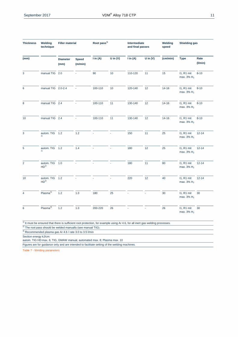
September 2017 VDMreg Alloy 718 CTP
12
Availability
VDMreg Alloy 718 CTP is available in the following standard semi-finished forms
Rod and bar
Delivery condition Forged rolled drawn heat treated (solution-annealed or age-hardened) oxidized descaled or pick-
led turned peeled ground or polished
Dimensions Outside diameter
mm (in)
Length
mm (in)
General dimensions 6-800 (024-3150) 1500-12000 (5906-47244)
Material specific dimensions 10-350 (039-1378) 1500-12000 (5906-47244)
Sheet and plate
Delivery condition Hot or cold rolled heat-treated descaled or pickled
Condition Thickness
mm (in)
Width
mm (in)
Length
mm (in)
Piece weight
Kg (lb)
Cold rolled 11-7 (004-028) le 2000 (7874) le 5500 (21654) le 1100 (2425)
Hot rolled 3-8 (012-031) le 2500 (9843) le 5500 (21654) le 1100 (2425)
Hot rolled 8-50 (031-197) le 2500 (9843) le 8000 (31496) le 1100 (2425)
Sheets can be manufactured considering the minimum and maximum dimensions
2 mm (008 in) thickness on request
Strip
Delivery condition Cold rolled heat treated pickled or bright annealed
Thickness
mm (in)
Width
mm (in)
Coil - inside diameter
mm
0025-015
(0001-0006)
4-230
(016-906)
300 400 500 ndash
015-025
(0006-001)
4-720
(016-2834)
300 400 500 ndash
025-06
(001-0024)
6-750
(024-295)
ndash 400 500 600
06-1
(0024-004)
8-750
(032-295)
ndash 400 500 600
1-2
(004-008)
15-750
(06-295)
ndash 400 500 600
2-3
(008-012)
25-750
(098-295)
ndash 400 500 600
Rolled sheet ndash separated from the coil ndash are available in lengths from 250 to 4000 mm (984 to 15748 in)
Wire
Delivery condition Drawn bright frac14 hard to hard bright annealed in rings containers on spools and spiders
Drawn
mm (in)
Hot rolled
mm (in)
016-10 (0006-04) 55-19 (022-075)
Other shapes and dimensions available on request
September 2017 VDMreg Alloy 718 CTP
13
Legal notice
01 September 2017
Publisher
VDM Metals International GmbH
Plettenberger Straszlige 2
58791 Werdohl
Germany
Disclaimer
All information contained in this data sheet is based on the results of research and development work carried out by
VDM Metals International GmbH and the data contained in the specifications and standards listed available at the time
of printing The information does not represent a guarantee of specific properties VDM Metals reserves the right to
change information without notice All information contained in this data sheet is compiled to the best of our knowledge
and is provided without liability Deliveries and services are subject exclusively to the relevant contractual conditions and
the General Terms and Conditions issued by VDM Metals International GmbH Use of the most up-to-date version of
this data sheet is the responsibility of the customer
VDM Metals GmbH
Plettenberger Strasse 2
58791 Werdohl
Germany
Phone +49 (0)2392 55 0
Fax +49 (0)2392 55 22 17
vdmvdm-metalscom
wwwvdm-metalscom


