VCF 850 series - dematec.pl · The VCF 850 Series is a new product of multi-purpose, vertical...
28
VCF 850 series Multi-purpose Vertical Machining Center VCF 850 series VCF 850 VCF 850L VCF 850SR VCF 850LSR ver. EN 180105 SU
Transcript of VCF 850 series - dematec.pl · The VCF 850 Series is a new product of multi-purpose, vertical...

VCF 850 series
Multi-purpose Vertical Machining Center
VCF 850 seriesVCF 850VCF 850LVCF 850SRVCF 850LSR
ver. EN 180105 SU
The VCF 850 Series is a new product of multi-purpose, vertical machining centers suitable for a wide range of applications. As a moving-column type of machine, the VCF 850 Series offers an X-axis travel distance of 3 meters, and enhanced work convenience and efficiency with the inclusion of various optional devices including a rotary table and center partition, leading to enhanced productivity and added value.
VCF 850 series
VCF 850
series
0302 /
Product Overview
Basic Information
Basic Structure
Cutting
Performance
Detailed
Information
Options
Applications
Capacity Diagram
Specifications
Customer Support
Service

Contents
02 Product Overview
Basic Information
04 Basic Structure
09 Cutting Performance
Detailed Information
10 Standard / Optional
Specifications
12 Applications
16 Capacity Diagram
20 Machine / NC Unit Specifications
26 Customer Support Service
Enhanced productivity with a wide range of applicability
Inclusion of rotary table, center partition, and pick-up magazine – features that will help the user to more than double machining efficiency.
Multi-purpose machine tool capable of simultaneous cutting with 3 to 5 axes
Simultaneous cutting operation from 3 to 5 axes (based on X-axis of 2 m and 3 m) – a real multi-purpose machine.
Fixed-type table providing the highest level of accuracy for a compact size
Compared to the same class of machine tools, the machine’s wider X axis and fixed table delivers greater accuracy for a more compact size.
Sample work
0302 /

VCF 850 / L
Multi-purpose Vertical Machining CenterThe VCF 850 Series is a new line of multifunctional machine tools developed according to a new design concept. Everything from small parts to the largest work pieces with complicated shapes can be mass produced with 3 to 5 selectable axes.
Swivel head
VCF 850SR / LSR
C-axis (integrated type)
B-axis
X-axis
Y-axis
Z-axis
Horizontal or
vertical type
C-axis
Fixed table, column moving structure realizes compact machine size with a wide X axis, maximizing the users' satisfaction.
Basic Structure
VCF 850
series
0504 /
Product Overview
Basic Information
Basic Structure
Cutting
Performance
Detailed
Information
Options
Applications
Capacity Diagram
Specifications
Customer Support
Service

High rigidity, high accuracy
Roller type
LM Guideway
Stable and Fast axes Structure Roller-type LM Guideways and high rigidity coupling realize high rigidity and outstanding accuracy of linear axes system.
Description Unit X Y Z
Travel distancemm
(inch)3000 {2000*}
(118.1 {78.7}*)850 (33.5) 800 (31.5)
Type Roller type
LMG structure rows 3 2 2
Rapid traversem/min (ipm)
40 (1574.8)
* All machines and all axes
* VCF 850
Cooling System for High Accuracy*The temperature of the ball screw nuts and bearing housings are maintained at optimal levels with a cooling system designed to minimize thermal error and maintain the rigidity of the feed system.
OILCOOLING
UNIT
˝P˝ ˝T˝
The linear axes are equipped with roller LM Guideways for increased rigidity and a cooling system as standard features to minimize thermal error.
Axis system
0504 /

Built-in SpindleDelivers the highest productivity and reliability at the lowest noise and vibration levels.
System TypeSpeed r/min
Spindle
Power kW (Hp)
TorqueN·m (ft-lb)
FANUCISO #40 12000
22 / 18.5 (29.5 / 24.8 )
210(155.0)
HEIDENHAIN32 / 24
(42.9 / 32.2)126
(93.0)
Dual-Face Locking Tool System Tool rigidity is enhanced by firm clamping by the spindle. Tool life cycle and cut-surface roughness are improved due to reduced vibration realized by dual-face locking.
Spindle CoolingThe oil cooler system is included as a standard feature to minimize thermal error over long periods of operation.
220˚ Rotatable B Axis220˚ rotatable spindle suitable for milling taper surfaces.
Type AxisSpeedr/min
Traveldeg
Rotary encoder
Worm gear B-axis 50 220 (+110, -110) Standard
B-axis 220° (±110°)
+110° -110°
Built-in spindles deliver outstanding reliability and are cooled down to minimize thermal error and guarantee excellent accuracy during long periods of operation.
Spindles
Taper contact Flange contactVCF 850
series
0706 /
Product Overview
Basic Information
Basic Structure
Cutting
Performance
Detailed
Information
Options
Applications
Capacity Diagram
Specifications
Customer Support
Service

Doosan's mounted or integrated rotary table is available according to the customer's requirements, e.g. shape cutting or side cutting to realize diverse solutions of excellent quality.
Rotary Table
Offers a competitive edge up to ø1050 of work size in an embedded structure.
Two types of rotary tables offer the ultimate in customer satisfaction Top-mounted attachable / detachable* rotary tables are available in a horizontal or vertical configuration according to the customer's requirements for various types of machining work.
TypeRotary table diameter
mm (inch)Max. work diameter
mm (inch)Rapid r/min
Load capacity kg (lb)
Mounted ø500 (19.7) ø730 (28.7) 30Vertical 600 (1322.8)
Horizontal** 300 (661.4)
Integrated ø800 (31.5) ø1050 (41.3) 25 1200 (2645.5)
Diameter
500 mm
(19.7 inch)
Vertical type Horizontal type
* Please consult us about the attachable/detachable configuration.
** For the rotary table only (excluding support).
Diameter
800 mm
(31.5 inch)
0706 /

Tool MagazineHigh durability and reliability of ATC by adopting a servo motor.
Drum type
30 tools
Chain type
60 tools
Specifications
Max tool diameter mm (inch) Max tool length
mm (inch)Max. tool weight
kg (lb)Continuous Adjacent pot empty
Standard 30T 80 130300 (11.8) 8 (17.6)
Optional 60T 76 130
Reliability further improved with the adoption of servo motors. Tool storage capacity can be extended up to 60 tools.
Magazine
Pickup Magazine An optional feature for tools with large diameters or lengths.
No. of Tools(ea)
Max tool diameter mm (inch) Max. tool length
mm (inch)Max. tool weight
kg (lb)Continuous Adjacent pot empty
5 150 (5.9) 230 (9.1) 450 (17.7) 8 (17.6)VCF 850
series
0908 /
Product Overview
Basic Information
Basic Structure
Cutting
Performance
Detailed
Information
Options
Applications
Capacity Diagram
Specifications
Customer Support
Service

Machining Performance
Foundation
Multiple-applicable functionality including end milling, face milling, drilling, tapping, etc. offers better machining performance while minimizing work setting.
Anchoring is recommended to ensure machining accuracy over a long time.
Machining PerformanceVCF 850 / L
Machine Foundation*Since machining accuracy is highly dependent on the machine’s foundation, anchoring is recommended to maintain accuracy over a long period of time. The anchor bolts and other related parts for foundation work are supplied as standard items.
Face mill Carbon steel (SM45C)
Toolmm (inch)
Spindle Speedr/min
Feed Ratemm/min (ipm)
Cutting Widthmm (inch)
Cutting Depthmm (inch)
Chip Removal Ratecm3/min (inch)
D80 (D3.1)
1200 3000 (118.1) 64 (2.5) 3.0 (0.1) 576 (35.1)1200 2400 (94.5) 64 (2.5) 4.0 (0.2) 614 (37.5)1200 1800 (70.9) 64 (2.5) 5.0 (0.2) 576 (35.1)1200 1400 (55.1) 64 (2.5) 6.0 (0.2) 538 (32.8)
U-Drill Carbon steel (SM45C)
Toolmm (inch)
Spindle Speedr/min
Feed Ratemm/min (ipm)
Cutting Depthmm (inch)
D50 (D2.0) 1080 240 (9.4) 50 (2.0)
TAP Carbon steel (SM45C)
Toolmm (inch)
Spindle Speedr/min
Feed Ratemm/min (ipm)
Cutting Depthmm (inch)
M36 x P4.0 (M1.4 x P0.2) 133 532 (20.9) 45 (1.8)M42 x P4.5 (M1.7 x P0.2) 114 513 (20.2) 45 (1.8)
VCF 850SR / LSR
Face mill Carbon steel (SM45C)
Toolmm (inch)
Spindle Speedr/min
Feed Ratemm/min (ipm)
Cutting Widthmm (inch)
Cutting Depthmm (inch)
Chip Removal Ratecm3/min (inch)
D80 (D3.1)
1500 2800 (110.2) 64 (2.6) 2.0 (0.1) 358 (21.8)1500 2280 (89.8) 64 (2.6) 2.5 (0.1) 365 (22.3)2420 4275 (168.3) 64 (2.6) 2.0 (0.1) 547 (33.4)
U-Drill Carbon steel (SM45C)
Toolmm (inch)
Spindle Speedr/min
Feed Ratemm/min (ipm)
Cutting Depthmm (inch)
D50 (D2.0)1005 203 (8.0) 45 (1.8)1257 25 (1.0) 245 (9.6)
TAP Carbon steel (SM45C)
Toolmm (inch)
Spindle Speedr/min
Feed Ratemm/min (ipm)
Cutting Depthmm (inch)
M24 x P3.0 (M0.9 x P0.1) 200 600 (23.6) 30 (1.2)M30 x P3.5 (M1.2 x P0.1) 160 560 (22.0) 35 (1.4)
* Please consult with Doosan sales technicians regarding ground and operating conditions.
*The results, indicated in this catalogue are provides as example. They may not be obtained due to differences in cutting conditions and environmental conditions during measurement.
0908 /
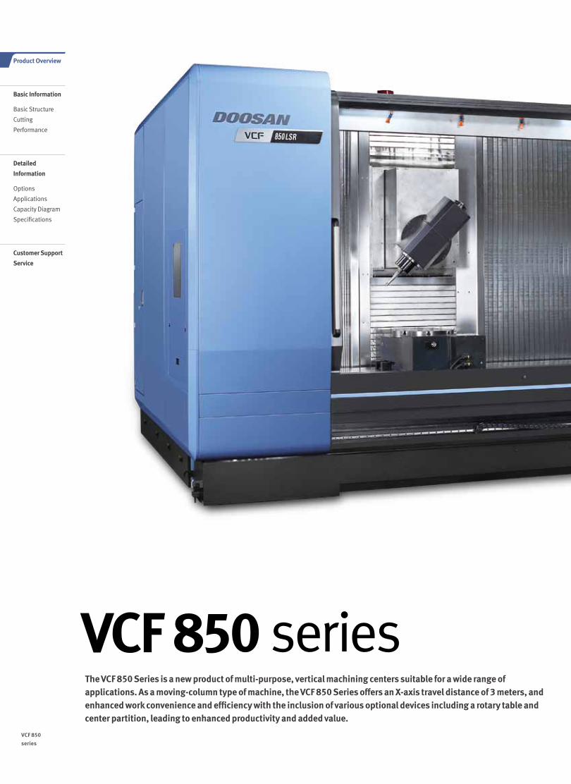
● Standard ◦ Optional X N/A
NO. Description Features VCF 850 [L] VCF 850 SR [LSR]
1Tool magazine
30 tools ● ●
2 60 tools ◦ ◦
3
Tool shank type
BIG PLUS BT40 ● ●
4 BIG PLUS CAT40 ◦ ◦
5 BIG PLUS DIN40 ◦ ◦
6 HSK 63A ◦ ◦
7 Auto door lock ● ●
8Rotary table
Ø500 (mounted) X ◦
9 Ø800 (integrated) X ◦
10
Linear scale
X-axis ◦ ◦
11 Y-axis ◦ ◦
12 Z-axis ◦ ◦
13Components for
installationFoundation bolt set ● ●
14 Center partition ◦ ◦
15
Spindle
12000 r/min22/18.5 kW (FANUC) ● ◦
32/24 kW (HEIDENHAIN) ◦ ●
16 18000 r/min ◦ ◦
17 Spindle head cooling system ● ●
18 Thermal error compensation system ● ●
19 Swivel head X ●
20Spindle motor power
22/18.5 kW (29.5 / 24.8 Hp) (FANUC) ● ◦
21 32/24 kW (42.9 / 32.2 Hp) (HEIDENHAIN) ◦ ●
22 Auto tool measuring
device
TS27R_RENISHAW ◦ ◦
23 TT140_HEIDENHAIN ◦ ◦
24Auto work measuring
device
OMP60_RENISHAW ◦ ◦
25 RMP60_RENISHAW ◦ ◦
26 TS640_HEIDENHAIN ◦ ◦
27Master tool for auto tool
measurementCALIBRATION BLOCK ◦ ◦
28 Auto power cut-off ◦ ●
29 Chip bucket ◦ ◦
30
Chip conveyor
Chip pan ● ●
31 Hinged type ◦ ◦
32 Scraper type ◦ ◦
33 Drum type ◦ ◦
34
Coolant
FLOOD (0.9 kW_0.44MPa) ● ●
35 FLUSHING ● ●
36 SHOWER ◦ ◦
37 BED CHIP FLUSHING ● ●
38 Coolant gun ◦ ◦
39 Test bar ◦ ◦
40 Table size 2500 [3500] x 870mm (98.4 [137.8] x 34.3 inch) ● ●
41 Pickup Magazine ◦ ◦
42AIR
AIR BLOWER ◦ ◦
43 AIR GUN ◦ ◦
44 MPG Portable MPG ● ●
45
NC Controller
DOOSAN-FANUC i ● ◦
46 FANUC 31i-5 X ◦
47 HEIDENHAIN iTNC530 ◦ ●
48 OIL SKIMMER BELT TYPE ◦ ◦
49 RAISED COLUMN X X
50
TSC
NONE ● ●
51 1.5 kW_2.0 MPa ◦ ◦
52 3.7 kW_2.0 MPa ◦ ◦
53 5.5 kW_7.0 MPa ◦ ◦
* Please consult us about high-speed specifications.For more details, please contact Doosan.
Diverse optional features are available for customer-specific requirements.
Standard / Optional Specifications
VCF 850
series
1110 /
Product Overview
Basic Information
Basic Structure
Cutting
Performance
Detailed
Information
Options
Applications
Capacity Diagram
Specifications
Customer Support
Service

Productivity is maximized by partitioning the table into two working areas.
A area- machining
B area- loading / unloading work
Intelligent Kinematic Compensation for 5-axis Recommended Option
For high accuracy 5-axis machining, Intelligent Kinematic Compensation function is recommended. This function minimizes error in complex 5-axis machining applications by
maintaining tip of the tool in correct position in respect to the workpiece. In order to properly utilize this function, following four optional items are required.
Recommended optional items
1. Software
2. Receiver 3. Touch Probe 4. Datum ball
FANUC NC: DCP-i (Developed by DOOSAN) Heidenhain NC: Kinematic opt
Automatic work piece measurement device
Automatic tool length measurement device
Oil skimmerMinimum quantity lublication
Misting device
Peripheral Equipment
Center Partition Delivers machining efficiency equivalent to two tables, thereby maximizing productivity.
Measurement and Coolant14
1110 /

VCF 850 / LVarious solutions suitable for customer-specific applications support multi-purpose machining to realize high productivity.
3-axes standard machine
Small items, mass production
Long work piece machining as one piece 3-axes standard machining
Multi-functional application of table by center partitioning
We offer a wide range of solutions suitable for diverse customer-specific needs.
Applications
X-axis
Y-axis
Z-axis
VCF 850
series
1312 /
Product Overview
Basic Information
Basic Structure
Cutting
Performance
Detailed
Information
Options
Applications
Capacity Diagram
Specifications
Customer Support
Service

VCF 850SR / LSRVarious solutions suitable for customer-specific applications support multi-purpose machining to realize high productivity.
5 axes machine
- 4 + 1 axes
- 5 axes simultaneously
- X / Y / Z, B / C or X / Y / Z, B / A
C-axis
Horizontal or vertical type independent
Swivel headC-axis (integrated type)
B-axis
4 axis standard machining 4 axis rear-side divided standard machining 5 axis rear-side divided standard machining (Embedded rotary table)
5 axis rear-side divided standard machining (Top-mounted rotary table)
5 axis rear-side divided standard machining (Top-mounted rotary table)
+ additional axis + additional axis
5 axis rear-side divided standard machining (Embedded rotary table)
5 axes long workpiece machining (One-setting, continuous machining)
5 axes long workpiece machining (Tilting machining and end support)
VCF 850LSR only VCF 850LSR only
1312 /

FANUC 31i-5
Easy Operation PackageSetting up of tools, work pieces and programs, as well as troubleshooting for abnormal condition of main parts, is designed to minimize waiting time, maximize operational efficiency, and enhance operator convenience.
Data Registry Table
Provides tool information per POT in 2D graphics.
ATC Recovery Help
Assists the operator with troubleshooting in the event of an emergency stop or abnormal function of the ATC.
G Code List
Explanation / help topics for G-Code can be viewed on the screen.
Sensor Status Monitor
Provides views of the operation of the machine’s standard sensors and solenoid valves.
Table Moving for Setup
Table can be moved to work piece set-up position with simple key strokes.
Easy work coordinate setting
Function for simple setting up of work coordinates without the need for calculation.
M Code List
Explanation/help topics for M-Code can be viewed on the screen.
Tool Load Monitor
Detects tool damage and wear and tear, and prevents mechanical damage by setting limits on spindle and axis load (during cutting feed).
User-Friendly Operation PanelLarge 15inch screen and user-friendly operating function ensure convenient and efficient operation.
Designed for
user convenience
Convenient and intuitive UI
Optimized button size
High-visibility lamps
Long lifecycle buttons
Partitioned to prevent operator error
Convenient
option buttons
Detachable buttons
Spare I/O signal ports for optional devices
Customized
functionality
Customer-specific function switches
Available for auxiliary panel design
Design optimized for customers' needs based on extensive know-how
Large 15inch screen display
15 inch
10.4 inch
VCF 850
series
1514 /
Product Overview
Basic Information
Basic Structure
Cutting
Performance
Detailed
Information
Options
Applications
Capacity Diagram
Specifications
Customer Support
Service
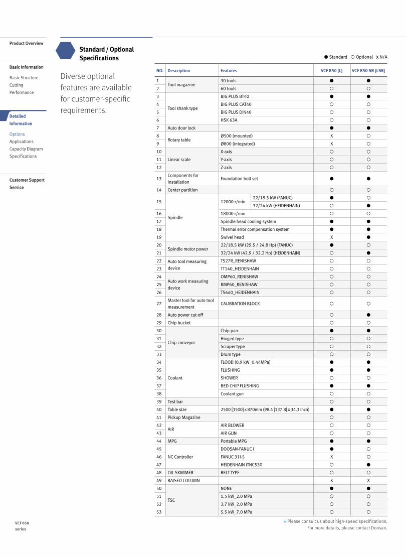
Superior Hardware Specifications15" LCD and capacious 21GB memory
Convenience
HEIDENHAIN iTNC530
Description HEIDENHAINiTNC530 Remarks
Screen size 15” STD -
Storage memory 21GB STD -
Interference prevention system
Optional -
Kinematic OPT. OptionalMeasuring device
not included
Look-ahead block 1024 blocks -
3D line graphics Std. -
15" LCD
Various built-in pattern cycles for a wider scope of application
Tool length, diameter, and work piece are
measured using stored tool measurement
graphic cycles.
Kinematic Opt (rotary axes tool center point)
Interactively (graphically)
supported fixed cycle enables
easy measurement of the centers
of the rotary axes
Collision Protection System
The motion of the machine can be simulated on a 3D
basis to substantially prevent mechanical interference.
(Tool length is also recognized.)
Graphic simulation
Before starting the actual cutting process,
a graphic process simulation of the NC
program can be carried out using TEST RUN.
The cutting time can be estimated.
Data are controlled in the folder structure; convenient communication via USB devices
15 inch
1514 /

Unit: mm (inch)
VCF 850
series
1716 /
Product Overview
Basic Information
Basic Structure
Cutting
Performance
Detailed
Information
Options
Applications
Capacity Diagram
Specifications
Customer Support
Service
VCF 850L
Top View
Front View
100
800
(Z S
TRO
KE)
790
(31.
1)
3000(118.1) (X STROKE)
1610 (1279) 1587 (1257)3196 (2536) (DOOR OPEN WIDTH)
MACHINE HOME POSITION
MAINTENANCE DOOR
POWER TRANSFORMER(OPTION)
T-S-C FILTER(OPTION)
HYD. POWER UNIT(4&5 AXIS)
CHIP BUCKET(OPTION)
CHIP CONVEYOR(OPTION)490
(19.3)
R
490
(19.3) R
545R
5440 (214.2)
5440 (214.2)
703 (27.7)
R 69
7(2
7.4)
1070
(42.
1)
1415 (55.7) 2
1415 (55.7) 2
3795
(149
.4) 45
85 (1
80.5
)
(21.5)
100
800
(Z S
TRO
KE)
790
(31.
1)
3000(118.1) (X STROKE)
1610 (1279) 1587 (1257)3196 (2536) (DOOR OPEN WIDTH)
MACHINE HOME POSITION
MAINTENANCE DOOR
POWER TRANSFORMER(OPTION)
T-S-C FILTER(OPTION)
HYD. POWER UNIT(4&5 AXIS)
CHIP BUCKET(OPTION)
CHIP CONVEYOR(OPTION)
490(19
.3)
R
490
(19.3) R
545R
5440 (214.2)
5440 (214.2)
703 (27.7)
R 69
7(2
7.4)
1070
(42.
1)
1415 (55.7) 2
1415 (55.7) 2
3795
(149
.4) 45
85 (1
80.5
)
(21.5)
External Dimensions

VCF 850LSR
Top View
Front View
External Dimensions
Unit: mm (inch)
1568 (61.7) 812 (32.0)
CHIP BUCKET(OPTION)
1200
(47
.2)
CHIP CONVEYOR_LEFT SIDE
POWER TRANSFORMER(OPTION)
545
(21.5) R
R490
490
R
5440 (214.2)
1568 (61.7) 812 (32.0) 5440 (214.2)
790
(31.
1)
3795
(149
.4)
4585
(180
.5)
(19.3)
(19.3)
R 697
(27.4)
1568 (61.7) 812 (32.0)
CHIP BUCKET(OPTION)
1200
(47
.2)
CHIP CONVEYOR_LEFT SIDE
POWER TRANSFORMER(OPTION)
545
(21.5) R
R490
490
R
5440 (214.2)
1568 (61.7) 812 (32.0) 5440 (214.2)
790
(31.
1)
3795
(149
.4)
4585
(180
.5)
(19.3)
(19.3)
R 697
(27.4)
1716 /

VCF 850
series
1918 /
Spindle Power – Torque Curve / Tool ShankProduct Overview
Basic Information
Basic Structure
Cutting
Performance
Detailed
Information
Options
Applications
Capacity Diagram
Specifications
Customer Support
Service
Unit : inchCAT #40Unit : mm (inch)DIN #40Unit : mm (inch)BT #40
(DIN shape) (DIN shape)
THREAD “T”
0.90.80.21.01.1
Ø 0
.9
Ø 0
.6
Ø 0
.8Ø
0.3
16.1
(0.6
)
22.6(0.9)
22.6(0.9)
M16�P2.0
Ø 7
HO
LEØ
23
(0.9
) Ø 1
4 0.
6)
Ø 1
9(0
.7)
Ø 1
7 (0
.7)
25 (1.0)
23 (0.9)
29 (1.1)
2 (0.1)4 (0.2)
15˚
30˚
16.6 (0.7) TAPER GAUGE LINE
7/24 TAPER
M16�P2.0
10 (0.4)
Ø 6
3 (2
.5)
Ø 5
3 (2
.1)
Ø 1
7(0
.7)
Ø 4
4.5
(1.8
)
60˚L
2 (0.1)65.4 (2.6)
TAPER GAUGE LINE7/24 TAPER
M16�P2.0
60˚
15.9 (0.6) 68.4 (2.7)35 (1.4)
11.1(0.4)
3.2 (0.1)
Ø 7
2.3
(2.8
)Ø
63.
6 (2
.5)
Ø 7 (0.3)
Ø 5
0 (2
.0)
Ø 1
7 (0
.7)
Ø 4
4.5
(1.8
)
2.85
0.4360˚
0.6 2.70.1 GAUGE PIN
7/24 TAPERTAP “T”
Ø 2
.5
Ø 0.3 (GAUGE PIN)
Ø 2
.2
Ø 0
.7H
7
1.8
18.5(0.7)
25 (1.0) 22.8 (0.9)
18.5
(0.7
)
16.1
(0.6
)
0.9 1.0
0.6
M16�P2.0
28 (1.1) 26 (1.0)4 (0.2)
2 (0.1)20 (0.8)
15˚
30˚
Ø 2
3 (0
.9)
Ø 1
7 (0
.7)
Ø 1
4(0
.6) Ø
19
(0.7
)
Ø 7
(0.3
) HO
LE
Tool Shank
Spindle Power – Torque Curve
[FANUC] 12000 r/min [HEIDENHAIN] 12000 r/min
Spindle Motor : 22 / 18.5 kW (29.5 / 24.8 Hp)
14.7 (19.7)17.7 (23.7)
18.5(24.8)
22 (29.5)
147.3 (108.7)119.4 (88.1)
204.2 (150.7) S3 ( 25 % )
S2 ( 15 min )
S1 ( Cont ) S1 ( Cont )
S2 ( 30 min )
120003000
28368651
19.1(25.6)
21.7 (29.1)
24 (32.2)27.3 (36.6)32 (42.9)
94.7 (69.9)
126.3 (93.2)
S1 ( Cont )S1 ( Cont )
S6 ( 40% - ED 2min )S6 ( 40% - ED 2min )
120002420 103001
Torq
ue :
N. m
Out
put :
kW
Spindle speed : r/min
Spindle Motor : 32 / 24 kW (42.9 / 32.2 Hp)
Torq
ue :
N. m
14.7 (19.7)17.7 (23.7)
18.5(24.8)
22 (29.5)
147.3 (108.7)119.4 (88.1)
204.2 (150.7) S3 ( 25 % )
S2 ( 15 min )
S1 ( Cont ) S1 ( Cont )
S2 ( 30 min )
120003000
28368651
19.1(25.6)
21.7 (29.1)
24 (32.2)27.3 (36.6)32 (42.9)
94.7 (69.9)
126.3 (93.2)
S1 ( Cont )S1 ( Cont )
S6 ( 40% - ED 2min )S6 ( 40% - ED 2min )
120002420 103001
Spindle speed : r/min
Out
put :
kW

1918 /
Table
Unit : mm (inch)
3500 {2500}* (137.8 {98.4}*)
135
(5.3
)13
5(5
.3)
250 (9.8)
210
(8.3
)
CENTER BUSH #1
870
(34.
3)
18(0.7)
+0.027
+0.2 0
+0.041 0.020
0 ( H8 )
12 (0.5
) 30 (1.2
)
30(1.2)
+0.2
22 (0
.9)
Ø30(1.2)
( F7 )
+0.021 0Ø30
(1.2)( F7 )
135
(5.3
)15
0 X
4 =
600
(5.9
X 4
= 2
3.6)
870
(34.
3)
150
X 4
= 6
00(5
.9 X
4 =
23.
6)
135
(5.3
)
3500 (137.8)1130 (44.5)
435
(17.
1)
CENTER BUSH #2
Ø930(3
6.6)
Ø800
(31.5)
CENTER BUSH #2
Ø500
(19.7)
45°
45°
Ø204(8.0)
12 (0.5
)
(18)
(0.7
)
870
(34.
3)
135
(5.3
)13
5(5
.3)
2500 (98.4)1250 (49.2)
435
(17.
1)
CENTER BUSH #2
Ø930
(36.
6)
150
X 4
= 60
0(5
.9 X
4 =
23.
6)
Ø800(31.5)
Rigid Table
Rigid Table W/D800 Built_in Rotary Table
VCF 850 LSR (X axis 3m)
VCF 850SR (X axis 2m)
* { } : option
D500 Rotary Table T-slot Detail Center Bush #1 Detail Center Bush #2 Detail
3500 {2500}* (137.8 {98.4}*)
135
(5.3
)13
5(5
.3)
250 (9.8)
210
(8.3
)
CENTER BUSH #1
870
(34.
3)
18(0.7)
+0.027
+0.2 0
+0.041 0.020
0 ( H8 )
12 (0.5
) 30 (1.2
)
30(1.2)
+0.2
22 (0
.9)
Ø30(1.2)
( F7 )
+0.021 0Ø30
(1.2)( F7 )
135
(5.3
)15
0 X
4 =
600
(5.9
X 4
= 2
3.6)
870
(34.
3)
150
X 4
= 6
00(5
.9 X
4 =
23.
6)
135
(5.3
)
3500 (137.8)1130 (44.5)
435
(17.
1)
CENTER BUSH #2
Ø930(3
6.6)
Ø800
(31.5)
CENTER BUSH #2
Ø500
(19.7)
45°
45°
Ø204(8.0)
12 (0.5
)
(18)
(0.7
)
3500 {2500}* (137.8 {98.4}*)13
5(5
.3)
135
(5.3
)
250 (9.8)
210
(8.3
)
CENTER BUSH #1
870
(34.
3)
18(0.7)
+0.027
+0.2 0
+0.041 0.020
0 ( H8 )
12 (0.5
) 30 (1.2
)
30(1.2)
+0.2
22 (0
.9)
Ø30(1.2)
( F7 )
+0.021 0Ø30
(1.2)( F7 )
135
(5.3
)15
0 X
4 =
600
(5.9
X 4
= 2
3.6)
870
(34.
3)
150
X 4
= 6
00(5
.9 X
4 =
23.
6)
135
(5.3
)
3500 (137.8)1130 (44.5)
435
(17.
1)
CENTER BUSH #2
Ø930(3
6.6)
Ø800
(31.5)
CENTER BUSH #2
Ø500
(19.7)
45°
45°
Ø204(8.0)
12 (0.5
)
(18)
(0.7
)

VCF 850series
Item Unit VCF 850 [ L ] VCF 850SR [ LSR ]
Travels
Travel distance
X-axis mm (inch) 2000 [3000] (78.7 [118.1])
Y-axis mm (inch) 850 (33.5)
Z-axis mm (inch) 800 (31.5)
B-axis deg - 220 (+110, -110)
Distance from spindle center to table top
mm (inch)100 ~ 900
(3.9 ~ 35.4)
MountedRotaryTable
Distance between Spindle nose &
Table top
100 ~ 900 (3.9 ~ 35.4)
Distance between B axis center &
Table top
435 ~ 1235(17.1 ~ 48.6)
IntegratedRotaryTable
Distance between Spindle nose &
Table top
-40 ~ 760 (-1.6 ~ 29.9)
Distance between B axis center &
Table top
295 ~ 1095 (11.6 ~ 43.1)
Feed rateRapid traverse rate X, Y, Z axes
m/min (ipm)
40 (1574.8)
Rapid rotating speed
B-axis r/min - 50
Cutting feedrate
X, Y, Z axesmm/min
(ipm)20000 (787.4)
B, C-axis deg/min 7200
Table Table size mm (inch) 2500 x 870 [3500 x 870] (98.4 x 34.3 [137.8 x 34.3])
Loading capacity kg (lb) 3500 (7716.1)
Table type T-SLOT (5-150 x 18H8)
Rotary Table
D500 D800
Table type T-SLOT (5-150 x 18H8)
Table size mm (inch) Ø 500 (Ø 19.7) Ø 800 (Ø 31.5)
Travel distance deg - 360
Rapid rotating speed r/min - 30 25
Max. work diameter mm (inch) - Ø 730 (Ø 28.7) Ø 1050 (Ø 41.3)
Max. work height mm (inch) -490 (19.3) (V), 905 (35.6) (H)
680 (2.9) (V), 1095 (43.1) (H)
Max. work weight kg (lb) -600 (1322.8) (V), 300 (661.4) (H)
1200 (2645.5)
Spindle Max. spindle speed r/min 12000 {18000}*
Spindle taper ISO #40, 7/24 TAPER
Max. spindle torque (HEIDENHAIN) N·m (ft-lb) 126.27 (93.2) (S6 40%) / 94.7 (69.9)
Max. spindle torque (FAUNC) N·m (ft-lb) 204 (150.6) (25 % ED)
Automatic Tool Changer
Tool shank type BT 40 {CAT 40 / DIN / HSK-A63}*
Tool storage capacity ea 30 {60}*
Max. tool diameter
Continuous mm (inch) 80 {76}* (3.1 {3.0})
Near port empty mm (inch) 130 (5.1)
Max. tool length mm (inch) 300 (11.8)
Max. tool weight kg (lb) 8 (17.6)
Max. tool moment N·m (ft-lbs) 5.88 (4.3)
Tool selection RANDOM ADDRESS
Tool change time (tool to tool) s 5.5
Tool change time (chip to chip) s 13
Motor Spindle motor power (HEIDENHAIN) kW (Hp) 32 / 24 (42.9 / 32.2)
Spindle motor power (FAUNC) kW (Hp) 22 / 18.5 (29.5 / 24.8)
Coolant pump motor power kW (Hp) 0.9 (1.2)
Power Source
Power consumption (HEIDENHAIN) kVA 60
Power consumption (FANUC) kVA 54
Compressed air pressure MPa 0.54
Tank Capacity
Coolant tank capacity L (galon) VCF 850 [SR] : 520 (137.4) VCF 850L [LSR] : 560 (148.0)
Lubricant tank capacity L (galon) 8.4 (2.2)
Machine Dimensions
Height mm (inch) 3205 (126.2)
Length mm (inch) 3795 (149.4)
Width mm (inch) 4440 [5440] (174.8 [214.2])
Weight kg (lb)VCF 850 [SR] : 22000 (48501.0)
VCF 850L [LSR] : 24000 (52910.2)
ControlStandard
DOOSAN-FANUC i
HEIDENHAIN iTNC 530
OptionHEIDENHAIN
iTNC 530 FANUC 31i-5
DOOSAN-FANUC i
* { } : OptionVCF 850
series
2120 /
Machine SpecificationsProduct Overview
Basic Information
Basic Structure
Cutting
Performance
Customer Support
Service
Detailed
Information
Options
Applications
Capacity Diagram
Specifications

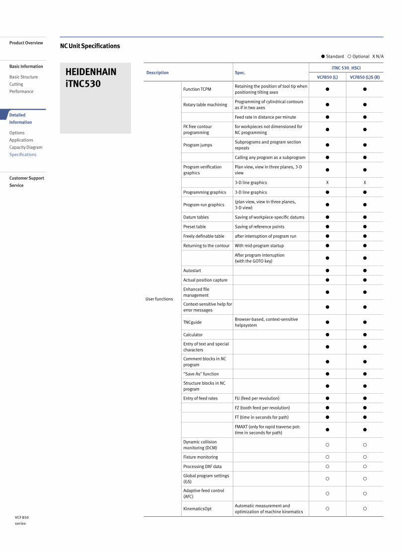
NC Unit Specifications
Description Spec.iTNC 530_HSCI
VCF850 (L) VCF850 (L)S (R)
Axes
Controlled axes
3 axes X, Y, Z X
4 axes ◦ X
5 axes X X, Y, Z, B, (5)
Additional controlled axes 6 axes X ◦
Controlled axes Max. 18 axes in total ◦ ◦
Least command increment 0.0001 mm (0.0001 inch), 0.0001° ● ●
Least input increment 0.0001 mm (0.0001 inch), 0.0001° ● ●
Maximum commandable value ±99999.999mm (±3937 inch) ● ●
Axis feedback controlDouble-speed control loops for high-frequency spindles and torque/linear motors
◦ ◦
MDI / DISPLAY unit 15.1 inch TFT color flat panel ● ●
19 inch TFT color flat panel ◦ ◦
Program memory for NC programs SSDR 21GB 21GB
Block processing time 0.5 ms 0.5 ms
Cycle time for path interpolation CC 61xx 3 ms 3 ms
Encoders Absolute encoders EnDat 2.2 EnDat 2.2
Commissioning and diagnostics
Data interfaces Ethernet interface ● ●
USB interface (USB 2.0) ● ●
Machine functions
Look-aheadIntelligent path control by calculating the path speed ahead of time (max. 1024 blocks.)
● ●
HSC filters ● ●
Switching the traverse ranges ● ●
User functions
Program input According to ISO ● ●
With smarT.NC ● ●
With smartSelect X X
Position entryNominal positions for lines and arcs in Cartesian coordinates
● ●
Incremental or absolute dimensions ● ●
Display and entry in mm or inches ● ●
Display of the handwheel path during machining with handwheel superimpositioning
● ●
Paraxial positioning blocks ● ●
Tool compensation In the working plane and tool length ● ●
Radius-compensated contour lookahead for up to 99 blocks (M120)
● ●
Three-dimensional tool radius compensation
● ●
Tool table Central storage of tool data ● ●
Multiple tool tables with any number of tools
● ●
Cutting-data tableCalculation of spindle speed and feed rate based on stored tables
● ●
Constant contouring speedrelative to the path of the tool center or to the tool's cutting edge
● ●
Parallel operationCreation of a program while another program is being run
● ●
Tilting the working plane with Cycle 19 ● ●
Tilting the working plane with the PLANE function
● ●
Manual traverse in tool-axis direction after interruption of program run ● ●
HEIDENHAIN iTNC530
● Standard ◦ Optional X N/A
2120 /
NC Unit Specifications
HEIDENHAIN iTNC530
Description Spec.iTNC 530_HSCI
VCF850 (L) VCF850 (L)S (R)
User functions
Function TCPMRetaining the position of tool tip when positioning tilting axes
● ●
Rotary table machiningProgramming of cylindrical contours as if in two axes
● ●
Feed rate in distance per minute ● ●
FK free contour programming
for workpieces not dimensioned for NC programming
● ●
Program jumpsSubprograms and program section repeats
● ●
Calling any program as a subprogram ● ●
Program verification graphics
Plan view, view in three planes, 3-D view
● ●
3-D line graphics X X
Programming graphics 3-D line graphics ● ●
Program-run graphics(plan view, view in three planes,3-D view)
● ●
Datum tables Saving of workpiece-specific datums ● ●
Preset table Saving of reference points ● ●
Freely definable table after interruption of program run ● ●
Returning to the contour With mid-program startup ● ●
After program interruption (with the GOTO key)
● ●
Autostart ● ●
Actual position capture ● ●
Enhanced file management
● ●
Context-sensitive help for error messages
● ●
TNCguideBrowser-based, context-sensitive helpsystem
● ●
Calculator ● ●
Entry of text and special characters
● ●
Comment blocks in NC program
● ●
"Save As" function ● ●
Structure blocks in NC program
● ●
Entry of feed rates FU (feed per revolution) ● ●
FZ (tooth feed per revolution) ● ●
FT (time in seconds for path) ● ●
FMAXT (only for rapid traverse pot: time in seconds for path)
● ●
Dynamic collision monitoring (DCM)
◦ ◦
Fixture monitoring ◦ ◦
Processing DXF data ◦ ◦
Global program settings (GS)
◦ ◦
Adaptive feed control (AFC)
◦ ◦
KinematicsOptAutomatic measurement and optimization of machine kinematics
◦ ◦
● Standard ◦ Optional X N/A
VCF 850
series
2322 /
Product Overview
Basic Information
Basic Structure
Cutting
Performance
Detailed
Information
Options
Applications
Capacity Diagram
Specifications
Customer Support
Service

Description Spec.iTNC 530_HSCI
VCF850 (L) VCF850 (L)S (R)
User functions
KinematicsComp Three-dimensional compensation ◦ ◦
3D-ToolCompDynamic 3-D tool radius compensation
◦ ◦
FUNCTION MODE TURN Switchover to turning mode X X
FUNCTION MODE MILL Switchover to milling mode X X
TOOLTURN.TRN Tool table for turning tools X X
Tool compensation for turning X X
FUNCTION TURNDATA SPIN VCONST ON VC:253
Constant surface speed with optional spindle speed limiting
X X
FUNCTION TURNDATA BLANK Blank-form update during turning X X
GRV AXIAL, GRV RADIAL Undercut as contour element X X
UDC TYPERecess as contour element, types E, F, H, K, U, threads
X X
Imbalance monitoringCycles for determining and monitoring imbalance
X X
Fixed cycles
Working plane Cycle 19 ● ●
Cylinder surface Cycle 27 ● ●
Cylinder surface slot milling Cycle 28 ● ●
Cylinder surface ridge milling Cycle 29 ● ●
Touch probe cycles
Calibrating the effective radius on a circular stud
X X
Calibrating the effective radius on a sphere X X
Cycles for automatic workpiece inspection
Calibrate TS ● ●
Calibrate TS length ● ●
Measure axis shift ● ●
Save kinematics ◦ ◦
Measure kinematics ◦ ◦
Preset compensation ◦ ◦
Options
Software option 1 ● ●
Rotary table machiningProgramming of cylindrical contours as if in two axes
Feed rate in mm/min
Coordinate transformationTilting the working plane, PLANE function
InterpolationCircular in 3 axes with tilted working plane
Software option 2 ● ●
3-D machining3-D tool compensation through surface normal vectors
Tool center point management (TCPM)
Keeping the tool normal to the contour
Tool radius compensation normal to the tool direction
InterpolationLine in 5 axes (subject to export permit)
Spline: execution of splines (3rd degree polynomial)
* { } : Option
NC Unit Specifications
HEIDENHAIN iTNC530
● Standard ◦ Optional X N/A
2322 /

FANUC Description Spec. DOOSAN-FANUC i
FANUC 31i-5
AXES
CONTROL
Controlled axes 3 (X, Y, Z) X, Y, Z, B, (5) X, Y, Z, B, (5)
Additional controlled axes 5 axes in total ● ●
Least command increment 0.001 mm / 0.0001" ● ●
Least input increment 0.001 mm / 0.0001" ● ●
Interpolation type pitch error
compensation◦ ◦
INTERPOLATION
& FEED
FUNCTION
2nd reference point return G30 ● ●
3rd / 4th reference return ● ●
Inverse time feed ● ◦
Cylinderical interpolation G07.1 ● ◦
Helical interpolation B Only Fanuc 30i - ◦
Smooth interpolation - ◦
NURBS interpolation - ◦
Involute interpolation - ◦
Helical involute interpolation - ◦
Bell-type acceleration/deceleration
before look ahead interpolation● ●
Smooth backlash compensation ◦ ●
Automatic corner override G62 ● ◦
Manual handle feed Max. 3unit 1 unit 1 unit
Manual handle feed rate x1, x10, x100 (per pulse) ● ●
Handle interruption ● ◦
Manual handle retrace ◦ ◦
Manual handle feed 2/3 unit - ◦
Nano smoothing AI contour control II is required. ◦ ●
AI APC 20 BLOCK X X
AICC I 30 BLOCK X X
AICC I 40 BLOCK X X
AICC II 200 BLOCK ● ●
AICC II 400 BLOCK - ◦
High-speed processing 600 BLOCK - ◦
Look-ahead blocks expansion 1000 BLOCK - ◦
DSQ IAICC II (200block) + Machining
condition selection function- ●
DSQ II
AICC II (200block) + Machining
condition selection function
+ Data server(1GB)
- ◦
DSQ III
AICC II with high speed
processing (600block) +
Machining condition selection
function + Data server(1GB)
- ◦
SPINDLE
& M-CODE
FUNCTION
M- code function ● ●
Retraction for rigid tapping ● ●
Rigid tapping G84, G74 ● ●
TOOL
FUNCTION
Number of tool offsets 64 ea - 64 ea
Number of tool offsets 99 ea - ◦
Number of tool offsets 200 ea - ◦
Number of tool offsets 400 ea 400 ea ◦
Number of tool offsets 499 / 999 / 2000 ea - ◦
Tool nose radius compensation G40, G41, G42 ● ●
Tool length compensation G43, G44, G49 ● ●
Tool life management ● ●
Addition of tool pairs for tool life
management● ◦
Tool offset G45 - G48 ● ◦
● Standard ◦ Optional X N/A
VCF 850
series
2524 /
NC Unit SpecificationsProduct Overview
Basic Information
Basic Structure
Cutting
Performance
Detailed
Information
Options
Applications
Capacity Diagram
Specifications
Customer Support
Service

FANUC Description Spec. DOOSAN-FANUC i
FANUC 31i-5
PROGRAMMING
& EDITING
FUNCTION
Custom macro ● ●
Macro executor ● ●
Extended part program editing ● ●
Part program storage 256KB(640m) - 640m
Part program storage 512KB(1,280m) 1280m ◦
Part program storage 1MB(2,560m) - ◦
Part program storage 2MB(5,120m) ◦ ◦
Part program storage 4MB(1,0240m) - ◦
Part program storage 8MB(2,0480m) - ◦
Inch/metric conversion G20 / G21 ● ●
Number of Registered programs 400 ea 400 ea -
Number of Registered programs 500 ea - 500 ea
Number of Registered programs 1000 ea - ◦
Number of Registered programs 4000 ea - ◦
Optional block skip 9 BLOCK ● ◦
Optional stop M01 ● ●
Program file name 32 characters - ●
Program number O4-digits ● -
Playback function ● ◦
Addition of workpiece coordinate system G54.1 P1 - 48 (48 pairs) 48 pairs 48 pairs
Addition of workpiece coordinate system G54.1 P1 - 300 (300 pairs) - ◦
OTHERS
FUNCTIONS
(Operation,
setting
& Display, etc)
Embeded Ethernet ● ●
Graphic display Tool path drawing ● ●
Loadmeter display ● ●
Memory card interface ● ●
USB memory interface Only Data Read & Write ● ●
Operation history display ● ●
DNC operation with memory card ● ●
Optional angle chamfering / corner R ● ●
Run hour and part number display ● ●
High speed skip function ● ◦
Polar coordinate command G15 / G16 ● ◦
Polar coordinate interpolation G12.1 / G13.1 - ◦
Programmable mirror image G50.1 / G51.1 ● ◦
Scaling G50, G51 ● ◦
Single direction positioning G60 ● ◦
Pattern data input ● ◦
Jerk control AI contour control II is required. ◦ ◦
Fast Data server with1GB PCMCIA card ◦ ◦
Fast Ethernet ◦ ◦
3-dimensional coordinate conversion ● ●
3-dimensional tool compensation - ◦
Figure copying G72.1, G72.2 - ◦
Machining time stamp function - ◦
EZ Guide I with 10.4" Color TFT
Doosan infracore Conversational
Programming Solution
-.When the EZ Guide i is used,
the Dynamic graphic display cannot
application
◦ ◦
Dynamic graphic display
(with 10.4" Color TFT LCD)
-.Machining profile drawing.
-.When the EZ Guide i is used,
the Dynamic graphic display cannot
application
◦ ◦
● Standard ◦ Optional X N/A
2524 /
NC Unit Specifications

Responding to Customers Anytime, Anywhere
Global Service Support Network
Technical Center: Sales Support, Service Support, Parts Support
5Corporations
3Factories
18Technical Centers
122Dealer Networks
AMERICA EUROPE
VCF 850
series
2726 /
Product Overview
Basic Information
Basic Structure
Cutting
Performance
Detailed
Information
Options
Applications
Capacity Diagram
Specifications
Customer Support
Service

Doosan Machine Tools’ Global Network, Responding to Customer’s Needs nearby, Anytime, AnywhereDoosan machine tools provides a system-based professional support service before and after the machine tool sale by responding quickly and efficiently to customers’ demands.By supplying spare parts, product training, field service and technical support, we can provide top class support to our customers around the world.
We help customers to achieve
success by providing a variety of
professional services from pre-
sales consultancy to post-sales
support.
Customer Support Service
- On site service- Machine installation and testing- Scheduled preventive maintenance- Machine repair
Field Services
- Supports machining methods and technology
- Responds to technical queries- Provides technical consultancy
Technical Support
- Programming / machine setup and operation
- Electrical and mechanical maintenance
- Applications engineering
Training
- Supplying a wide range of original Doosan spare parts
- Parts repair service
Supplying Parts
Domestic Service Support Network
2Integrated Support Centers 7
Sales Branch Offices
6Post-Sales Service Centers 31
Designated Repair Service Centers
CHINA (Yantai)
CHINA (Shanghai)
INDIA
Changwon Factory
Head Office
JAPAN
2726 /

Main Specifications
VCF 850 series Specification UNIT VCF 850 [L] / VCF 850SR [LSR]
Max. spindle speed r/min 12000
Max. spindle torque (HEIDENHAIN) N·m (ft-lbs) 126 (93.0)
Max. spindle torque (FAUNC) N·m (ft-lbs) 204 (150.6)
Spindle motor power (HEIDENHAIN) kW (Hp) 32 / 24 (42.9 / 32.2)
Spindle motor power (FAUNC) kW (Hp) 22 / 18.5 (29.5 / 24.8)
Tool storage capacity ea 30 { 60 }*
Dimensions (H x L x W) mm (inch)3205 x 3795 x 4440 [5440]
(126.1 x 149.4 x 178.8 [214.2])
*{ } Optional
Head OfficeYeonkang Bldg., 6th FL., 270, Yeonji-dong,
Jongno-gu, Seoul, Korea
Tel +82-2-3670-5345 / 5362
Fax +82-2-3670-5382
Doosan Machine Tools America19A Chapin Rd., Pine Brook, NJ 07058, U.S.A.
Tel +1-973-618-2500
Fax +1-973-618-2501
Doosan Machine Tools ChinaRoom 101,201,301, Building 39 Xinzhuan Highway
No.258 Songjiang District,China Shanghai(201612)
Tel +86 21-5445-1155
Fax +86 21-6405-1472
Doosan Machine Tools EuropeEmdener Strasse 24, D-41540 Dormagen, Germany
Tel +49-2133-5067-100
Fax +49-2133-5067-111
Doosan Machine Tools Japan#2412, Mita Kokusai Bldg. 1-4-28 Mita,
Minato-ku, Tokyo 108-0073, Japan
Tel +81 3 5730 9013
Fax +81 3 5730 9016
Doosan Machine Tools India106 / 10-11-12, Amruthahalli, Byatarayanapura,
Bellary road, Bangalore-560 092, India
Tel +91-80-4266-0122 / 121 / 100
* For more details, please contact Doosan Machine Tools.* The specifications and information above-mentioned may be changed without prior notice.* Doosan Machine Tools Co., Ltd. is a subsidiary of MBK Partners. The trademark is used under a licensing agreement with Doosan Corporation,
the registered trademark holder.
Doosan Machine Toolshttp://www.doosanmachinetools.com
www.facebook.com/doosanmachinetools www.youtube.com/c/DoosanMachineToolsCorporation
There is a high risk or fire when using non-water-soluble cutting fluids, processing flammable materials, neglecting use coolants and modifyingthe machine without the consent of the manufacturer. Please check the SAFETY GUIDANCE carefully before using the machine.
Fire Safety Precautions