
Vc Cookbook
200
Virtual Connect FlexFabric Cookbook (Version 3.30 and 3.51 Firmware Enhancements) Part number: c02616817 Second Edition February 2012
-
Upload
gigisuperduru -
Category
Documents
-
view
71 -
download
4
Transcript of Vc Cookbook
Virtual Connect FlexFabric Cookbook (Version 3.30 and 3.51 Firmware Enhancements)
Part number: c02616817 Second Edition February 2012

© Copyright 2012 Hewlett-Packard Development Company, L.P.
The information contained herein is subject to change without notice. The only warranties for HP products and services are set forth in the express warranty statements accompanying such products and services. Nothing herein should be construed as constituting an additional warranty. HP shall not be liable for technical or editorial errors or omissions contained herein.
Contents
Purpose ................................................................................................................................................. 5
Introduction to Virtual Connect Flex-10 and FlexFabric ................................................................................ 6 New Features: ......................................................................................................................................... 6 Determining Network Traffic Patterns and Virtual Connect network design (Active/Active vs. Active/Standby) ... 17 Choosing Flex-10 or FlexFabric ............................................................................................................... 17 VMware ESXi 5.0 .................................................................................................................................. 18
Single Domain/Enclosure Scenarios ....................................................................................................... 20 Overview .............................................................................................................................................. 20
Requirements .................................................................................................................................... 20
Scenario 1 – Simple vNet with Active/Standby Uplinks – Ethernet and FCoE – Windows 2008 R2 .............. 22 Overview .............................................................................................................................................. 22
Requirements .................................................................................................................................... 22 Installation and configuration................................................................................................................... 24
Switch configuration .......................................................................................................................... 24 Review ................................................................................................................................................. 31
Results – Windows 2008 R2 Networking Examples ............................................................................... 32 Results – Windows 2008 R2 SAN Connectivity..................................................................................... 37
Summary .............................................................................................................................................. 38
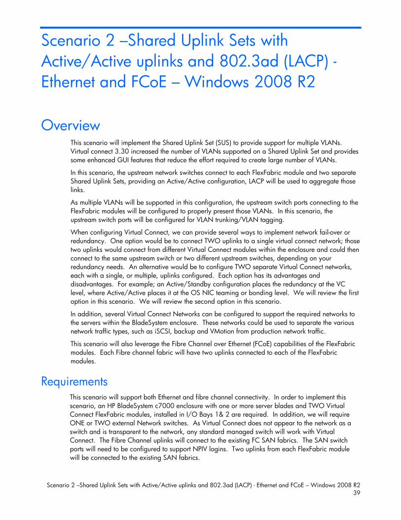
Scenario 2 –Shared Uplink Sets with Active/Active uplinks and 802.3ad (LACP) - Ethernet and FCoE – Windows 2008 R2 .............................................................................................................................. 39
Overview .............................................................................................................................................. 39 Requirements .................................................................................................................................... 39
Installation and configuration................................................................................................................... 41 Switch configuration .......................................................................................................................... 41
Review ................................................................................................................................................. 50 Results – Windows 2008 R2 Networking Examples ............................................................................... 50 Results – Windows 2008 R2 SAN Connectivity..................................................................................... 55
Summary .............................................................................................................................................. 56
Scenario 3 – Shared Uplink Set with Active/Active Uplinks and 802.3ad (LACP) - Ethernet and FCoE Boot from SAN – Windows 2008 R2 .................................................................................................................... 57
Overview .............................................................................................................................................. 57 Requirements .................................................................................................................................... 57 Switch configuration .......................................................................................................................... 59
Review ................................................................................................................................................. 68 Results – Windows 2008 R2 Networking Examples ............................................................................... 68 Results – Windows 2008 R2 SAN Connectivity..................................................................................... 74
Summary .............................................................................................................................................. 75
Scenario 4 – Shared Uplink Set with Active/Active Uplinks and 802.3ad (LACP) - Ethernet and FCoE SAN - Windows 2008 R2 Hyper-V .................................................................................................................. 76
Overview .............................................................................................................................................. 76 Requirements .................................................................................................................................... 76
Installation and configuration................................................................................................................... 78 Switch configuration .......................................................................................................................... 78
Review ................................................................................................................................................. 88 Results – Windows 2008 R2 Networking Examples ............................................................................... 89 Results – Windows 2008 R2 SAN Connectivity................................................................................... 100
Summary ............................................................................................................................................ 101
Scenario 5 – Shared Uplink Set with Active/Standby Uplinks and 802.3ad (LACP) - Ethernet and FCoE SAN - vSphere ............................................................................................................................................ 102
Overview ............................................................................................................................................ 102 Requirements .................................................................................................................................. 102
Installation and configuration................................................................................................................. 104 Switch configuration ........................................................................................................................ 104
Review ............................................................................................................................................... 115 Results – vSphere Networking Examples ............................................................................................. 116 Results – vSphere SAN Connectivity .................................................................................................. 121
Summary ............................................................................................................................................ 122
Scenario 6 – Shared Uplink Set with Active/Active Uplinks and 802.3ad (LACP) - Ethernet and FCoE SAN - vSphere ............................................................................................................................................ 123
Overview ............................................................................................................................................ 123 Requirements .................................................................................................................................. 123
Installation and configuration................................................................................................................. 125 Switch configuration ........................................................................................................................ 125
Review ............................................................................................................................................... 135 Results – vSphere Networking Examples ............................................................................................. 136 Results – vSphere SAN Connectivity .................................................................................................. 141
Summary ............................................................................................................................................ 142
Scenario 7 – Tunneled VLANs and Shared Uplink Set with Active/Active Uplinks and 802.3ad (LACP) - Ethernet and FCoE SAN - vSphere .................................................................................................................... 143
Overview ............................................................................................................................................ 143 Requirements .................................................................................................................................. 143
Installation and configuration................................................................................................................. 145 Switch configuration ........................................................................................................................ 145
Review ............................................................................................................................................... 156 Results – vSphere Networking Examples ............................................................................................. 156 Results – vSphere SAN Connectivity .................................................................................................. 161
Summary ............................................................................................................................................ 162
Scenario 8 – Network Access Groups in a Shared Uplink Set - Ethernet and FCoE SAN – Windows 2008R2 ........................................................................................................................................................ 163
Overview ............................................................................................................................................ 163 Requirements .................................................................................................................................. 163
Installation and configuration................................................................................................................. 165 Switch configuration ........................................................................................................................ 165
Review ............................................................................................................................................... 175 Results – Windows 2008 R2 Networking Examples ............................................................................. 176
Summary ............................................................................................................................................ 181
Appendix A1 – Scenario-based CISCO IOS Command Line Reference ..................................................... 182
Appendix A2 – Scenario-based CISCO NX-OS Command Line Reference ................................................ 186
Appendix B – Scenario-based ProCurve Command Line Reference ........................................................... 190
Appendix C – Acronyms and abbreviations .......................................................................................... 194
Appendix D – Useful VC CLI Command sets .......................................................................................... 196 VC Domain Configuration ................................................................................................................ 196 FlexFabric Scripting Additions .......................................................................................................... 198 Release 3.30 Scripting Additions ...................................................................................................... 199
Purpose
The purpose of this Virtual Connect Cookbook is to provide users of Virtual Connect with a better understanding of the concepts and steps required when integrating HP BladeSystem and Virtual Connect Flex-10 or FlexFabric components into an existing network.
The scenarios in this Cookbook vary from simplistic to more complex while covering a range of typical building blocks to use when designing Virtual Connect Flex-10 or FlexFabric solutions. Although these scenarios are shown individually, some scenarios could be combined to create a more complex and versatile Virtual Connect environment, such as the combined use of Shares Uplink Sets (SUS) and vNet Tunnels. Existing users of Virtual Connect will quickly realize that as of VC firmware release 3.30 that the selection between “Mapped” and “Tunneled” modes are no longer of concern. The capabilities provided in those modes are now available in the default installation of VC firmware 3.30 and beyond. These capabilities and changes will be discussed in further detail later in this paper.
The scenarios as written are meant to be self-contained configurations and do not build on earlier scenarios, with this you may find some repetition or duplication of configuration across scenarios.
This paper is not meant to be a complete or detailed guide to Virtual Connect Flex-10 or FlexFabric, but is intended to provide the reader with some valid examples of how Virtual Connect Flex-10 or FlexFabric could be deployed within their environments. Many additional configurations or scenarios could also be implemented. Please refer to the following section for additional reference material on Virtual Connect, Flex-10 and FlexFabric.
Documentation feedback HP welcomes your feedback. To make comments and suggestions about product documentation, send a message to [email protected]. Include the document title and manufacturing part number. All submissions become the property of HP.
Introduction to Virtual Connect Flex-10 and FlexFabric 6
Introduction to Virtual Connect Flex-10 and FlexFabric
Virtual Connect is an industry standards-based implementation of server-edge virtualization. It puts an abstraction layer between the servers and the external networks so the LAN and SAN see a pool of servers rather than individual servers. Once the LAN and SAN connections are physically made to the pool of servers, the server administrator uses Virtual Connect management tools (Virtual Connect Manager (VCM) or Virtual Connect Enterprise Manager (VCEM)) to create an Interconnect modules connection profile for each server.
Virtual Connect FlexFabric is an extension to Virtual Connect Flex-10 which leverages the new Fibre Channel over Ethernet (FCoE) protocols. By leveraging FCoE for connectivity to existing Fibre Channel SAN networks, we can reduce the number of switch modules and HBAs required within the server blade. This in turn further reduces cost, complexity, power and administrative overhead.
This paper will discuss the differences between Flex-10 and FlexFabric and provide information and suggestions to assist the reader in determining the best option for their implementation of BladeSystem and Virtual Connect. For additional information on Virtual Connect, Flex-10 and/or FlexFabric, please review the documents below.
New Features: Virtual Connect Firmware 3.30 includes the following new features:
Command Line Interface Telemetry—Provides improved reporting and metrics from the VC domain and individual VC-Enet modules. New metrics include CPU load, memory utilization, discover information, port statistics, L2 MAC address table, IGMP groups, link aggregation information, VC networks information, interfaces information, throughput information, and module hostname control.
Network Access Groups for profile—Allows a VC network administrator to define specific subsets of domain networks. Network subsets are then associated with each profile, which limits the network connections to those subsets.
Simultaneous tunneled and mapped VLAN connections—In earlier versions, these modes were mutually exclusive within a VC domain
Increased mapped VLAN capacity—The number of VLANs supported in a shared uplink set is increased from 128 to 1000. The number of connections on a server downlink has been increased from 28 to 162. Additional CLI and GUI commands have been added to support management of multiple networks with a single command.
Enhanced port status—Provides additional status and information on link status Simplified iSCSI boot setup—Automatically retrieves parameters from HP 4000 SAN solutions
and attaches them to server profiles. This feature significantly reduces required manual entries. GUI Profile Wizard support (Ethernet, iSCSI, FC, FCoE) New CLI commands—New CLI commands to support save and restore configurations, copy
profiles, and the show config command that generates a CLI script that can be used to restore the current VC domain configuration
Native IE8 browser support—Running in IE7 emulation is no longer required
Introduction to Virtual Connect Flex-10 and FlexFabric 7
Loop avoidance—Specific detection of Cisco PVST BPDUs emerging from servers are added, and when found, result in disabling of the server-facing physical port generating them and an administrative alert being sent.
IGMPv3 snooping support (no support for Source-specific multicast) TACACS+/RADIUS role based security—User authentication, Command Authorization, and
Command logging Updated SNMP MIBs—Severity level added to all traps (alerts) to improve notification Support for user-defined login screen notice (typically a security message) Support—Log File Compression has been added, which provides the ability to capture more
support information Notification of unsupported cables—The HP VC FlexFabric 10Gb/24-Port module does not
support DAC cables longer than 5m for uplink ports X1–X4. Starting with this release, a port status of "unsupported" is displayed if an unsupported DAC cable is attached to any of the uplink ports X1–X4. This limitation is documented in the QuickSpecs and the HP Virtual Connect for c-Class BladeSystem Setup and Installation Guide.
Improved integration with HP System Insight Manager. The HP VC 8Gb 20-Port FC Module firmware is now correctly returning several important elements of the HP MIBs as part of the System Insight Manager discovery.
Please refer to the VC 3.30 Release notes and User Guides for further information 3.30 Release Notes http://bizsupport1.austin.hp.com/bc/docs/support/SupportManual/c02996704/c02996704.pdf
3.30 CLI User Guide http://bizsupport2.austin.hp.com/bc/docs/support/SupportManual/c02996642/c02996642.pdf
3.30 User Guide http://bizsupport2.austin.hp.com/bc/docs/support/SupportManual/c02996013/c02996013.pdf
Virtual Connect Firmware 3.51 includes the following new features: Enhanced support for network loop protection Support for Internet Explorer 9.x Support for Mozilla Firefox 6.x and 7.x
Please refer to the VC 3.51 Release notes for further information 3.51 Release Notes http://bizsupport1.austin.hp.com/bc/docs/support/SupportManual/c03128002/c03128002.pdf
3.51 CLI User Guide http://bizsupport2.austin.hp.com/bc/docs/support/SupportManual/c02996642/c02996642.pdf
3.51 User Guide http://bizsupport2.austin.hp.com/bc/docs/support/SupportManual/c03128023/c03128023.pdf
Additional Virtual Connect Reference Material Link to HP Virtual Connect technology site, provides a great deal of reference information on Virtual connect, Flex-10 and FlexFabric. http://h18000.www1.hp.com/products/blades/virtualconnect/
Link to HP Virtual Connect technology for the HP BladeSystem c-Class, 5th edition when available http://h20000.www2.hp.com/bc/docs/support/SupportManual/c00814156/c00814156.pdf
Introduction to Virtual Connect Flex-10 and FlexFabric 8
Link to HP Virtual Connect for c-Class BladeSystem Setup and Installation Guide http://bizsupport1.austin.hp.com/bc/docs/support/SupportManual/c01732252/c01732252.pdf
Link to HP Flex-10 technology with FlexFabric components http://bizsupport2.austin.hp.com/bc/docs/support/SupportManual/c01608922/c01608922.pdf
Link to HP BladeSystem Network Reference Architecture - FlexFabric and VMware vSphere 4 http://h20195.www2.hp.com/v2/GetPDF.aspx/c02505638.pdf
Link to Virtual Connect User, Setup and CLI Guides http://h20000.www2.hp.com/bizsupport/TechSupport/DocumentIndex.jsp?contentType=SupportManual&lang=en&cc=us&docIndexId=64180&taskId=101&prodTypeId=3709945&prodSeriesId=3794423
HP Virtual Connect FlexFabric Solutions Recipe http://h20000.www2.hp.com/bc/docs/support/SupportManual/c02610285/c02610285.pdf
(www.hp.com/go/blades)
Virtual Connect Ethernet Cookbook Virtual Connect can be used to support both Ethernet and Fibre Channel connections. The Virtual Connect Ethernet Cookbook is provided with basic Virtual Connect configurations for both 1Gb and 10Gb solutions, whereas the Virtual Connect FlexFabric Cookbook provides additional scenarios that leverage the new FCoE protocols. If you are new to Virtual Connect it is highly recommended that you also review the existing Virtual Connect Ethernet Cookbook
This document replaces the original Virtual Connect Ethernet Cookbook, with Flex-10 scenarios.
Virtual Connect Ethernet (with Flex-10) Cookbook http://h20000.www2.hp.com/bc/docs/support/SupportManual/c01990371/c01990371.pdf
(www.hp.com/go/blades)
Virtual Connect Fibre Channel Cookbook Virtual Connect can be used to support both Ethernet and Fibre Channel connections; however, this guide is focused completely on the Ethernet configuration.
For Fibre Channel connectivity, please refer to the Virtual Connect Fibre Channel Cookbook http://bizsupport1.austin.hp.com/bc/docs/support/SupportManual/c01702940/c01702940.pdf
(www.hp.com/go/blades)
Virtual Connect iSCSI Cookbook Virtual Connect can be used to support iSCSI accelerated connections, including iSCSI boot, however, this guide is focused completely on the Ethernet and iSCSI configuration.
For iSCSI connectivity, please refer to the Virtual Connect iSCSI Cookbook
http://h20000.www2.hp.com/bc/docs/support/SupportManual/c02533991/c02533991.pdf
(www.hp.com/go/blades)
Introduction to Virtual Connect Flex-10 and FlexFabric 9
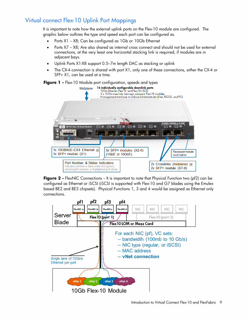
Virtual connect Flex-10 Uplink Port Mappings It is important to note how the external uplink ports on the Flex-10 module are configured. The graphic below outlines the type and speed each port can be configured as. Ports X1 – X8; Can be configured as 1Gb or 10Gb Ethernet Ports X7 – X8; Are also shared as internal cross connect and should not be used for external
connections, at the very least one horizontal stacking link is required, if modules are in adjacent bays.
Uplink Ports X1-X8 support 0.5–7m length DAC as stacking or uplink The CX-4 connection is shared with port X1, only one of these connections, either the CX-4 or
SFP+ X1, can be used at a time.
Figure 1 - Flex-10 Module port configuration, speeds and types
Figure 2 - FlexNIC Connections – It is important to note that Physical Function two (pf2) can be configured as Ethernet or iSCSI (iSCSI is supported with Flex-10 and G7 blades using the Emulex based BE2 and BE3 chipsets). Physical Functions 1, 3 and 4 would be assigned as Ethernet only connections.
Introduction to Virtual Connect Flex-10 and FlexFabric 10
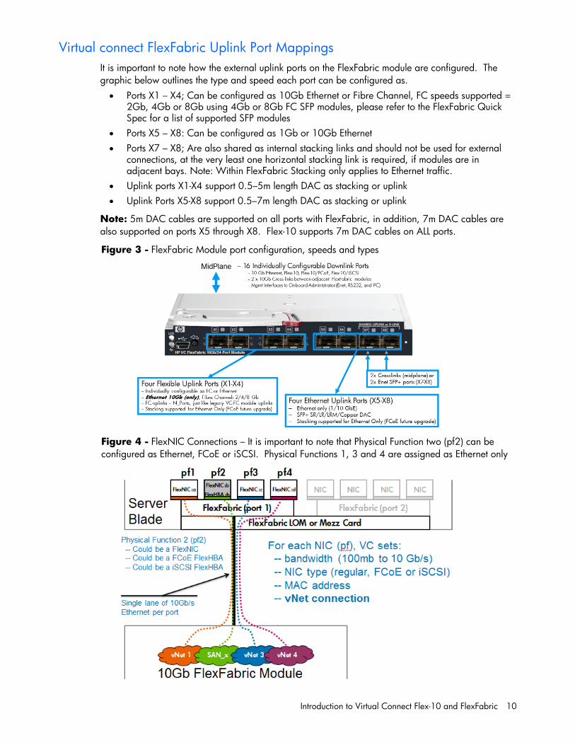
Virtual connect FlexFabric Uplink Port Mappings It is important to note how the external uplink ports on the FlexFabric module are configured. The graphic below outlines the type and speed each port can be configured as. Ports X1 – X4; Can be configured as 10Gb Ethernet or Fibre Channel, FC speeds supported =
2Gb, 4Gb or 8Gb using 4Gb or 8Gb FC SFP modules, please refer to the FlexFabric Quick Spec for a list of supported SFP modules
Ports X5 – X8: Can be configured as 1Gb or 10Gb Ethernet Ports X7 – X8; Are also shared as internal stacking links and should not be used for external
connections, at the very least one horizontal stacking link is required, if modules are in adjacent bays. Note: Within FlexFabric Stacking only applies to Ethernet traffic.
Uplink ports X1-X4 support 0.5–5m length DAC as stacking or uplink Uplink Ports X5-X8 support 0.5–7m length DAC as stacking or uplink
Note: 5m DAC cables are supported on all ports with FlexFabric, in addition, 7m DAC cables are also supported on ports X5 through X8. Flex-10 supports 7m DAC cables on ALL ports.
Figure 3 - FlexFabric Module port configuration, speeds and types
Figure 4 - FlexNIC Connections – It is important to note that Physical Function two (pf2) can be configured as Ethernet, FCoE or iSCSI. Physical Functions 1, 3 and 4 are assigned as Ethernet only
Introduction to Virtual Connect Flex-10 and FlexFabric 11
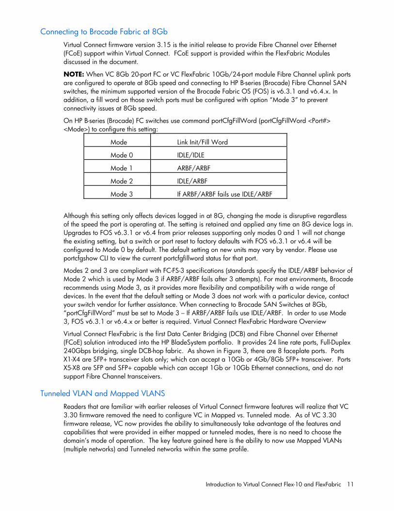
Connecting to Brocade Fabric at 8Gb Virtual Connect firmware version 3.15 is the initial release to provide Fibre Channel over Ethernet (FCoE) support within Virtual Connect. FCoE support is provided within the FlexFabric Modules discussed in the document.
NOTE: When VC 8Gb 20-port FC or VC FlexFabric 10Gb/24-port module Fibre Channel uplink ports are configured to operate at 8Gb speed and connecting to HP B-series (Brocade) Fibre Channel SAN switches, the minimum supported version of the Brocade Fabric OS (FOS) is v6.3.1 and v6.4.x. In addition, a fill word on those switch ports must be configured with option “Mode 3” to prevent connectivity issues at 8Gb speed.
On HP B-series (Brocade) FC switches use command portCfgFillWord (portCfgFillWord <Port#> <Mode>) to configure this setting:
Although this setting only affects devices logged in at 8G, changing the mode is disruptive regardless of the speed the port is operating at. The setting is retained and applied any time an 8G device logs in. Upgrades to FOS v6.3.1 or v6.4 from prior releases supporting only modes 0 and 1 will not change the existing setting, but a switch or port reset to factory defaults with FOS v6.3.1 or v6.4 will be configured to Mode 0 by default. The default setting on new units may vary by vendor. Please use portcfgshow CLI to view the current portcfgfillword status for that port.
Modes 2 and 3 are compliant with FC-FS-3 specifications (standards specify the IDLE/ARBF behavior of Mode 2 which is used by Mode 3 if ARBF/ARBF fails after 3 attempts). For most environments, Brocade recommends using Mode 3, as it provides more flexibility and compatibility with a wide range of devices. In the event that the default setting or Mode 3 does not work with a particular device, contact your switch vendor for further assistance. When connecting to Brocade SAN Switches at 8Gb, “portCfgFillWord” must be set to Mode 3 – If ARBF/ARBF fails use IDLE/ARBF. In order to use Mode 3, FOS v6.3.1 or v6.4.x or better is required. Virtual Connect FlexFabric Hardware Overview
Virtual Connect FlexFabric is the first Data Center Bridging (DCB) and Fibre Channel over Ethernet (FCoE) solution introduced into the HP BladeSystem portfolio. It provides 24 line rate ports, Full-Duplex 240Gbps bridging, single DCB-hop fabric. As shown in Figure 3, there are 8 faceplate ports. Ports X1-X4 are SFP+ transceiver slots only; which can accept a 10Gb or 4Gb/8Gb SFP+ transceiver. Ports X5-X8 are SFP and SFP+ capable which can accept 1Gb or 10Gb Ethernet connections, and do not support Fibre Channel transceivers.
Tunneled VLAN and Mapped VLANS Readers that are familiar with earlier releases of Virtual Connect firmware features will realize that VC 3.30 firmware removed the need to configure VC in Mapped vs. Tunneled mode. As of VC 3.30 firmware release, VC now provides the ability to simultaneously take advantage of the features and capabilities that were provided in either mapped or tunneled modes, there is no need to choose the domain’s mode of operation. The key feature gained here is the ability to now use Mapped VLANs (multiple networks) and Tunneled networks within the same profile.
Mode Link Init/Fill Word
Mode 0 IDLE/IDLE
Mode 1 ARBF/ARBF
Mode 2 IDLE/ARBF
Mode 3 If ARBF/ARBF fails use IDLE/ARBF
Introduction to Virtual Connect Flex-10 and FlexFabric 12
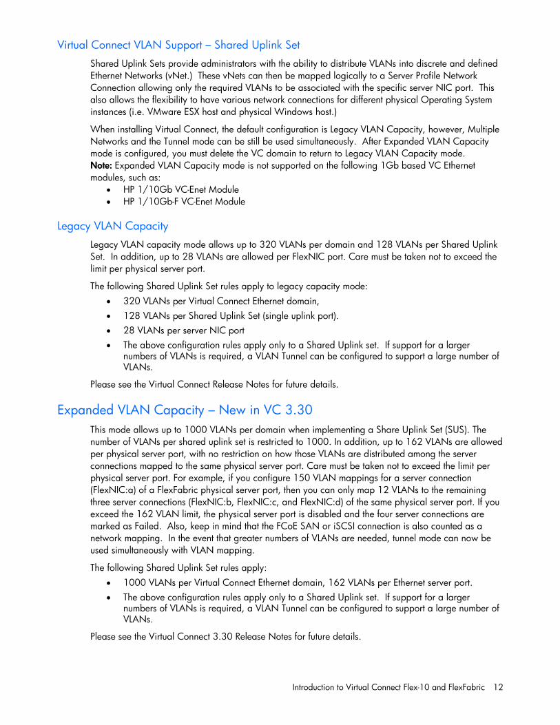
Virtual Connect VLAN Support – Shared Uplink Set Shared Uplink Sets provide administrators with the ability to distribute VLANs into discrete and defined Ethernet Networks (vNet.) These vNets can then be mapped logically to a Server Profile Network Connection allowing only the required VLANs to be associated with the specific server NIC port. This also allows the flexibility to have various network connections for different physical Operating System instances (i.e. VMware ESX host and physical Windows host.)
When installing Virtual Connect, the default configuration is Legacy VLAN Capacity, however, Multiple Networks and the Tunnel mode can be still be used simultaneously. After Expanded VLAN Capacity mode is configured, you must delete the VC domain to return to Legacy VLAN Capacity mode. Note: Expanded VLAN Capacity mode is not supported on the following 1Gb based VC Ethernet modules, such as:
HP 1/10Gb VC-Enet Module HP 1/10Gb-F VC-Enet Module
Legacy VLAN Capacity Legacy VLAN capacity mode allows up to 320 VLANs per domain and 128 VLANs per Shared Uplink Set. In addition, up to 28 VLANs are allowed per FlexNIC port. Care must be taken not to exceed the limit per physical server port.
The following Shared Uplink Set rules apply to legacy capacity mode: 320 VLANs per Virtual Connect Ethernet domain, 128 VLANs per Shared Uplink Set (single uplink port). 28 VLANs per server NIC port The above configuration rules apply only to a Shared Uplink set. If support for a larger
numbers of VLANs is required, a VLAN Tunnel can be configured to support a large number of VLANs.
Please see the Virtual Connect Release Notes for future details.
Expanded VLAN Capacity – New in VC 3.30 This mode allows up to 1000 VLANs per domain when implementing a Share Uplink Set (SUS). The number of VLANs per shared uplink set is restricted to 1000. In addition, up to 162 VLANs are allowed per physical server port, with no restriction on how those VLANs are distributed among the server connections mapped to the same physical server port. Care must be taken not to exceed the limit per physical server port. For example, if you configure 150 VLAN mappings for a server connection (FlexNIC:a) of a FlexFabric physical server port, then you can only map 12 VLANs to the remaining three server connections (FlexNIC:b, FlexNIC:c, and FlexNIC:d) of the same physical server port. If you exceed the 162 VLAN limit, the physical server port is disabled and the four server connections are marked as Failed. Also, keep in mind that the FCoE SAN or iSCSI connection is also counted as a network mapping. In the event that greater numbers of VLANs are needed, tunnel mode can now be used simultaneously with VLAN mapping.
The following Shared Uplink Set rules apply: 1000 VLANs per Virtual Connect Ethernet domain, 162 VLANs per Ethernet server port. The above configuration rules apply only to a Shared Uplink set. If support for a larger
numbers of VLANs is required, a VLAN Tunnel can be configured to support a large number of VLANs.
Please see the Virtual Connect 3.30 Release Notes for future details.
Introduction to Virtual Connect Flex-10 and FlexFabric 13
When installing Virtual Connect, the default configuration is Legacy VLAN Capacity, however, Multiple Networks and the Tunnel mode can be still be used simultaneously. After Expanded VLAN Capacity mode is configured, you must delete the VC domain to return to Legacy VLAN Capacity mode.
Note: Expanded VLAN Capacity mode is not supported on the following 1Gb based VC Ethernet modules, such as:
HP 1/10Gb VC-Enet Module HP 1/10Gb-F VC-Enet Module
If these modules are inserted into an enclosure that is in Expanded VLAN Capacity mode, they are marked as incompatible. If these modules are installed in an enclosure, converting to Expanded VLAN Capacity mode will not be permitted.
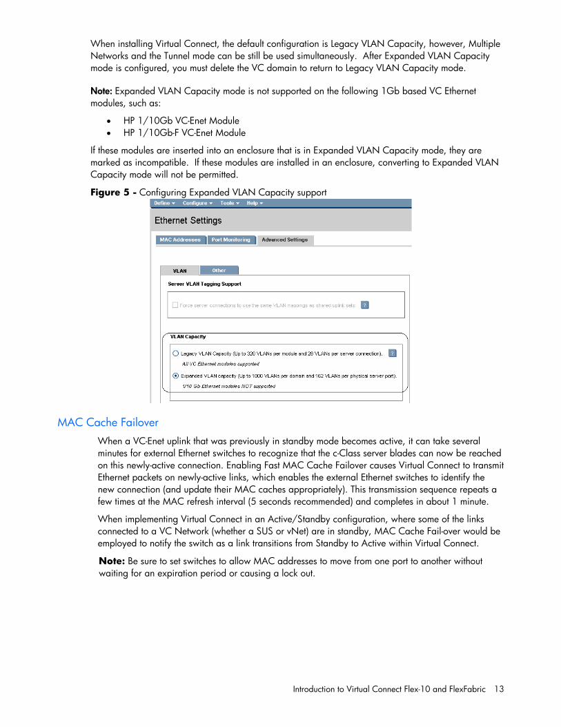
Figure 5 - Configuring Expanded VLAN Capacity support
MAC Cache Failover When a VC-Enet uplink that was previously in standby mode becomes active, it can take several minutes for external Ethernet switches to recognize that the c-Class server blades can now be reached on this newly-active connection. Enabling Fast MAC Cache Failover causes Virtual Connect to transmit Ethernet packets on newly-active links, which enables the external Ethernet switches to identify the new connection (and update their MAC caches appropriately). This transmission sequence repeats a few times at the MAC refresh interval (5 seconds recommended) and completes in about 1 minute.
When implementing Virtual Connect in an Active/Standby configuration, where some of the links connected to a VC Network (whether a SUS or vNet) are in standby, MAC Cache Fail-over would be employed to notify the switch as a link transitions from Standby to Active within Virtual Connect.
Note: Be sure to set switches to allow MAC addresses to move from one port to another without waiting for an expiration period or causing a lock out.
Introduction to Virtual Connect Flex-10 and FlexFabric 14
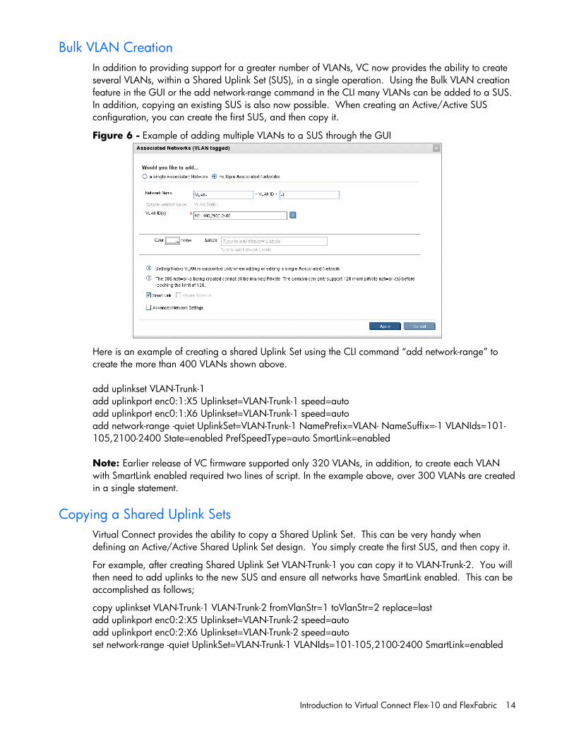
Bulk VLAN Creation In addition to providing support for a greater number of VLANs, VC now provides the ability to create several VLANs, within a Shared Uplink Set (SUS), in a single operation. Using the Bulk VLAN creation feature in the GUI or the add network-range command in the CLI many VLANs can be added to a SUS. In addition, copying an existing SUS is also now possible. When creating an Active/Active SUS configuration, you can create the first SUS, and then copy it.
Figure 6 - Example of adding multiple VLANs to a SUS through the GUI
Here is an example of creating a shared Uplink Set using the CLI command “add network-range” to create the more than 400 VLANs shown above.
add uplinkset VLAN-Trunk-1 add uplinkport enc0:1:X5 Uplinkset=VLAN-Trunk-1 speed=auto add uplinkport enc0:1:X6 Uplinkset=VLAN-Trunk-1 speed=auto add network-range -quiet UplinkSet=VLAN-Trunk-1 NamePrefix=VLAN- NameSuffix=-1 VLANIds=101-105,2100-2400 State=enabled PrefSpeedType=auto SmartLink=enabled Note: Earlier release of VC firmware supported only 320 VLANs, in addition, to create each VLAN with SmartLink enabled required two lines of script. In the example above, over 300 VLANs are created in a single statement.
Copying a Shared Uplink Sets Virtual Connect provides the ability to copy a Shared Uplink Set. This can be very handy when defining an Active/Active Shared Uplink Set design. You simply create the first SUS, and then copy it.
For example, after creating Shared Uplink Set VLAN-Trunk-1 you can copy it to VLAN-Trunk-2. You will then need to add uplinks to the new SUS and ensure all networks have SmartLink enabled. This can be accomplished as follows;
copy uplinkset VLAN-Trunk-1 VLAN-Trunk-2 fromVlanStr=1 toVlanStr=2 replace=last add uplinkport enc0:2:X5 Uplinkset=VLAN-Trunk-2 speed=auto add uplinkport enc0:2:X6 Uplinkset=VLAN-Trunk-2 speed=auto set network-range -quiet UplinkSet=VLAN-Trunk-1 VLANIds=101-105,2100-2400 SmartLink=enabled
Introduction to Virtual Connect Flex-10 and FlexFabric 15
Network Access Groups (NAG) Before VC 3.30, any server profile could be assigned any set of networks. If policy dictated that some networks should not be accessed by a system that accessed other networks (for example, the Intranet and the Extranet or DMZ networks) there was no way to enforce that policy automatically.
With VC 3.30 and later, network access groups are defined by the network administrator and associated with a set of networks that can be shared by a single server. Each server profile is associated with one network access group. A network cannot be assigned to the server profile unless the profile is a member of the network access group associated with that network. A network access group can contain multiple networks.
Up to 128 network access groups are supported in the domain. Ethernet networks and server profiles that are not assigned to a specific network access group are added to the domain Default network access group automatically. The Default network access group is predefined by VCM and cannot be removed or renamed.
If you are updating to VC 3.30, all current networks are added to the Default network access group and all server profiles are set to use the Default network access group. Network communication within the network access group behaves similarly to earlier versions of VC firmware, because all profiles can reach all networks.
If you create a new network access group, NetGroup1, and move existing networks from the Default network access group to NetGroup1, then a profile that uses NetGroup1 cannot use networks included in the Default network access group. Similarly, if you create a new network and assign it to NetGroup1 but not to the Default network access group, then a profile that uses the Default network access group cannot use the new network. Therefore, an administrator cannot inadvertently, or intentionally, place a server on networks that reside in different Network Access Groups.
vNets, Tunnels and Shared Uplink Sets
vNet There are two types of vNets. The first is a simple vNet that will pass only untagged frames. The second is a vNet tunnel which will pass tagged frames for one or many VLANs.
The vNet is a simple network connection between one or many server NICs to one or many uplink ports.
A vNet could be used to connect a single VLAN, no tagging, to one or many server NICs, if this network is part of a VLAN, by configuring the upstream switch port as an access or untagged port, by extension, any server connected to this vNet would reside in that VLAN, but would not need to be configured to interpret the VLAN tags.
Benefits of a vNet A vNet can be utilized in one of two ways, a simple vNet, used to pass untagged frames and a tunneled vNet. A tunneled vNet can be used to pass many VLANs without modifying the VLAN tags, functioning as a transparent VLAN Pass-Thru module.
vNet Tunnel A tunneled vNet will pass VLAN tagged frames, without the need to interpret or forward those frames based on the VLAN tag. Within a tunneled vNet the VLAN tag is completely ignored by Virtual Connect and the frame is forwarded to the appropriate connection (server NIC[s] or uplinks) depending on frame direction flow. In this case, the end server would need to be configured to interpret the VLAN tags. This could be a server with a local operating system, in which the network stack would need to
Introduction to Virtual Connect Flex-10 and FlexFabric 16
be configured to understand which VLAN the server was in, or a virtualization host with a vSwitch supporting multiple VLANs.
The tunneled vNet can support up to 4096 VLANs.
Benefits of a vNet Tunnel A vNet can present one or many VLANs to a server NIC. When additional VLANs are added to the upstream switch port, they are made available to service with no changes required within Virtual Connect. All presented VLANs are pass through the tunnel, unchanged.
Shared Uplink Set (SUS) The SUS provides the ability to support VLAN tagging and forward frames based on the VLAN tags of those frames. The SUS connects one or many server NICs to one or many uplink ports. A SUS would be configured for the specific VLANs it will support. If support for additional VLANs is required, those VLANs need to be configured within the SUS.
When connecting a server NIC to a network within a SUS, there are two choices provided. The key difference between these two options is the state in which the frame is passed to the server NIC. When configuring a server NIC for network connection;
1. Selecting a single network – which would be mapped to a specific VLAN.
If a single network is selected, the frames will be presented to the server NIC WITHOUT a VLAN tag. In this case the host operating system does not need to understand which VLAN it resides in. When the server transmits frames back to VC, those frames will not be tagged, however; Virtual Connect will add the VLAN tag and forward the frame onto the correct VLAN.
2. Selecting multiple networks – which would provide connectivity to several VLANs.
The Map VLAN Tags feature provides the ability to use a Shared Uplink Set to present multiple networks to a single NIC. If you select Multiple Networks when assigning a Network to a server NIC, you will have the ability to configure multiple Networks (VLANS) on that server NIC. At this point VC tags ALL the packets presented to the NIC — unless the Native check box is selected for one of the networks, in which case packets from this network (VLAN) will be untagged, and any untagged packets leaving the server will be placed on this Network (VLAN).
With Mapped VLAN Tags, you can create a Shared Uplink Set that contains ALL the VLANs you want to present to your servers, then present only ONE network (the one associated with the VLAN we want the server NIC in) to the Windows, LINUX or the ESX Console NIC, then select Multiple Networks for the NIC connected to the ESX vSwitch and select ALL the networks that we want presented to the ESX host vSwitch. The vSwitch will then break out the VLANs into port groups and present them to the guests. Using Mapped VLAN Tags minimizes the number of uplinks required.
Benefits of a SUS A Shared Uplink Set can be configure to support both tagged and un-tagged network traffic to a server NIC, which simplifies the overall configuration and minimizes the number of uplink cables required to support the network connections.
Introduction to Virtual Connect Flex-10 and FlexFabric 17
Determining Network Traffic Patterns and Virtual Connect network design (Active/Active vs. Active/Standby)
When choosing which Virtual Connect network design to use, consider the type of network traffic this enclosure will need to support. For example, will there be much server to server traffic needed within the enclosure, or is the traffic flow mainly in/out bound of the enclosure.
Network traffic patterns, North/South vs. East/West, should be considered when designing a Virtual Connect solution as network connectivity can be implemented in a way to maximize the connected bandwidth and/or minimize the need for server to server traffic to leave the enclosure when communicating on the same VLAN within the enclosure.
For example; if the solution being implemented will have a high level of in/out or North/South traffic flow, an Active/Active network design would likely be the better solution. However, if a greater level network traffic is between systems within the same enclosure/VLAN, such as a multi-tiered application, then a better design may be Active/Standby, as this would minimize or eliminate any server to server communications from leaving the enclosure.
Choosing Flex-10 or FlexFabric When choosing between Flex-10 and FlexFabric, the first question to ask is whether Fibre Channel connectivity will be required, today or in the future. The key difference between Flex-10 and FlexFabric is that FlexFabric modules leverage the built in Converged Network Adapter (CNA) provided in the G7 BladeSystem servers to provide FCoE (Fibre Channel) or iSCSI connectivity. FCoE connectivity is provided through the integrated Converged Network Adapter (CNA) and the FlexFabric modules, no additional components would be required, such as a traditional HBA.
If Fibre Channel support is not required, then all the capabilities of the CNA in the G7 Blade and Virtual Connect can be obtained through the use of the Flex-10 modules, the only feature not available would be Fibre Channel connectivity. Fibre Channel connectivity could be later added through the use of Virtual Connect Fibre Channel modules, and FC HBAs. Otherwise the main difference between Flex-10 and FlexFabric is how FlexFabric provides FCoE support, where Flex-10 does not. iSCSI support is provided through either FlexFabric or Flex-10 modules.
The Scenarios provided in this document could be implemented on either Flex-10 or FlexFabric modules. If Fibre Channel is not used, then the second FlexNIC on each port would be used for Ethernet. If Flex-10 modules are used with VC Fibre Channel modules, ensure an HBA is installing in the appropriate MEZZ slot in the blade and simply configure a “FC HBA” in the server profile and map it to the appropriate FC SAN Fabrics. In this case, FCoE SAN Fabrics and FCoE HBAs would not be used.
Introduction to Virtual Connect Flex-10 and FlexFabric 18
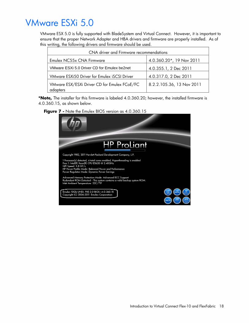
VMware ESXi 5.0 VMware ESX 5.0 is fully supported with BladeSystem and Virtual Connect. However, it is important to ensure that the proper Network Adapter and HBA drivers and firmware are properly installed. As of this writing, the following drivers and firmware should be used.
CNA driver and Firmware recommendations
Emulex NC55x CNA Firmware 4.0.360.20*, 19 Nov 2011
VMware ESXi 5.0 Driver CD for Emulex be2net 4.0.355.1, 2 Dec 2011
VMware ESXi50 Driver for Emulex iSCSI Driver 4.0.317.0, 2 Dec 2011
VMware ESX/ESXi Driver CD for Emulex FCoE/FC adapters
8.2.2.105.36, 13 Nov 2011
*Note, The installer for this firmware is labeled 4.0.360.20; however, the installed firmware is 4.0.360.15, as shown below.
Figure 7 - Note the Emulex BIOS version as 4.0.360.15
Introduction to Virtual Connect Flex-10 and FlexFabric 19
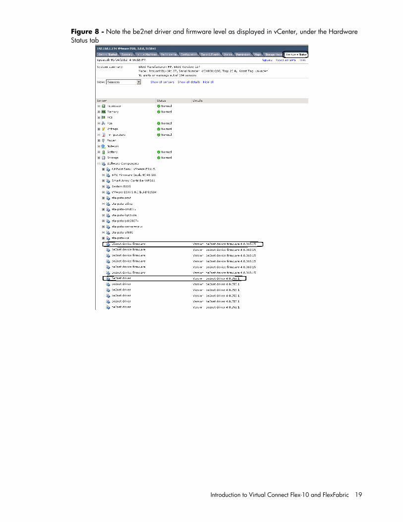
Figure 8 - Note the be2net driver and firmware level as displayed in vCenter, under the Hardware Status tab
Single Domain/Enclosure Scenarios 20
Single Domain/Enclosure Scenarios
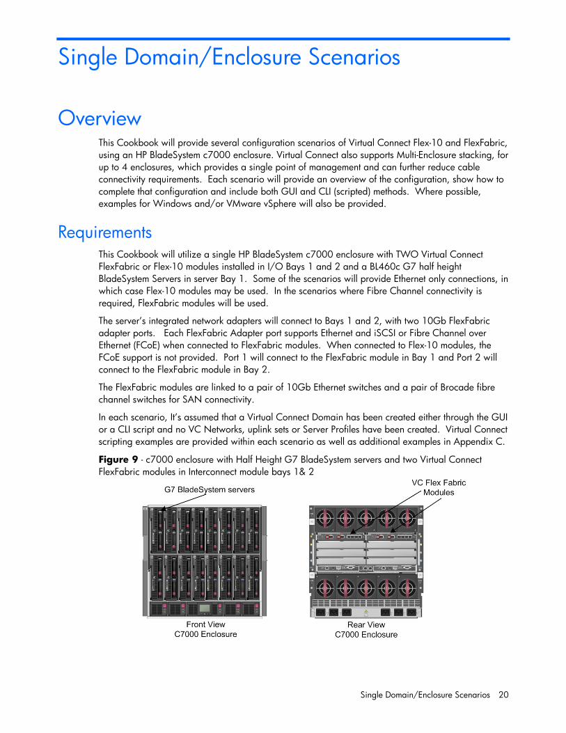
Overview This Cookbook will provide several configuration scenarios of Virtual Connect Flex-10 and FlexFabric, using an HP BladeSystem c7000 enclosure. Virtual Connect also supports Multi-Enclosure stacking, for up to 4 enclosures, which provides a single point of management and can further reduce cable connectivity requirements. Each scenario will provide an overview of the configuration, show how to complete that configuration and include both GUI and CLI (scripted) methods. Where possible, examples for Windows and/or VMware vSphere will also be provided.
Requirements This Cookbook will utilize a single HP BladeSystem c7000 enclosure with TWO Virtual Connect FlexFabric or Flex-10 modules installed in I/O Bays 1 and 2 and a BL460c G7 half height BladeSystem Servers in server Bay 1. Some of the scenarios will provide Ethernet only connections, in which case Flex-10 modules may be used. In the scenarios where Fibre Channel connectivity is required, FlexFabric modules will be used.
The server’s integrated network adapters will connect to Bays 1 and 2, with two 10Gb FlexFabric adapter ports. Each FlexFabric Adapter port supports Ethernet and iSCSI or Fibre Channel over Ethernet (FCoE) when connected to FlexFabric modules. When connected to Flex-10 modules, the FCoE support is not provided. Port 1 will connect to the FlexFabric module in Bay 1 and Port 2 will connect to the FlexFabric module in Bay 2.
The FlexFabric modules are linked to a pair of 10Gb Ethernet switches and a pair of Brocade fibre channel switches for SAN connectivity.
In each scenario, It’s assumed that a Virtual Connect Domain has been created either through the GUI or a CLI script and no VC Networks, uplink sets or Server Profiles have been created. Virtual Connect scripting examples are provided within each scenario as well as additional examples in Appendix C.
Figure 9 - c7000 enclosure with Half Height G7 BladeSystem servers and two Virtual Connect FlexFabric modules in Interconnect module bays 1& 2
Single Domain/Enclosure Scenarios 21
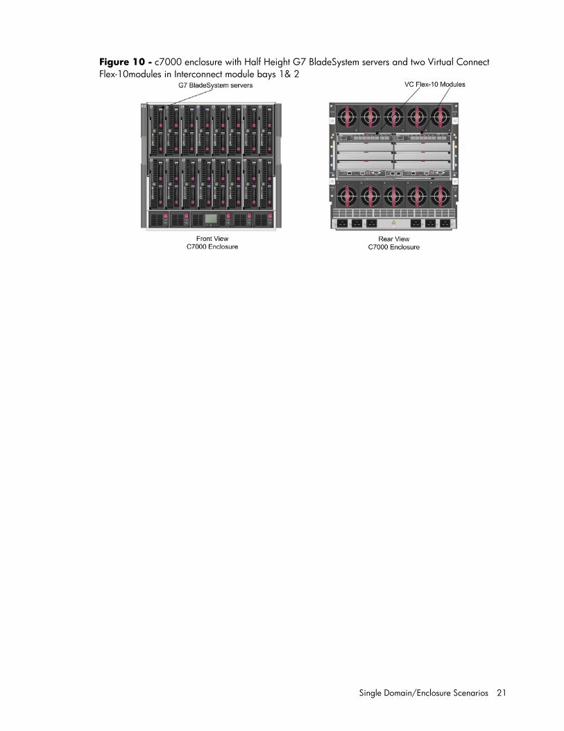
Figure 10 - c7000 enclosure with Half Height G7 BladeSystem servers and two Virtual Connect Flex-10modules in Interconnect module bays 1& 2

Scenario 1 – Simple vNet with Active/Standby Uplinks – Ethernet and FCoE – Windows 2008 R2 22
Scenario 1 – Simple vNet with Active/Standby Uplinks – Ethernet and FCoE – Windows 2008 R2
Overview This simple configuration uses the Virtual Connect vNet along with FCoE for SAN connectivity. When VLAN mapping is not required, the vNet is the simplest way to connect Virtual Connect to a network and server. In this scenario, the upstream network switch connects a network to a single port on each FlexFabric module. In addition, Fibre Channel uplinks will also be connected to the FlexFabric modules to connect to the existing Fibre Channel infrastructure.
No special upstream switch configuration is required as the switch is in the factory default configuration, typically configured as an Access or untagged port on either the default VLAN or a specific VLAN, either way, Virtual Connect does not receive VLAN tags.
When configuring Virtual Connect, we can provide several ways to implement network fail-over or redundancy. One option would be to connect TWO uplinks to a single vNet; those two uplinks would connect from different Virtual Connect modules within the enclosure and could then connect to the same or two different upstream switches, depending on your redundancy needs. An alternative would be to configure TWO separate vNets, each with a single, or multiple, uplink configured. Each option has its advantages and disadvantages. For example; an Active/Standby configuration places the redundancy at the VC level, where Active/Active places it at the OS NIC teaming or bonding level. We will review the first option in this scenario.
In addition, several vNets can be configured to support the required networks to the servers within the BladeSystem enclosure. These networks could be used to separate the various network traffic types, such as iSCSI, backup and VMotion from production network traffic.
This scenario will also leverage the Fibre Channel over Ethernet (FCoE) capabilities of the FlexFabric modules. Each Fibre channel fabric will have one uplink connected to each of the FlexFabric modules.
Requirements This scenario will support both Ethernet and fibre channel connectivity. In order to implement this scenario, an HP BladeSystem c7000 enclosure with one or more server blades and TWO Virtual Connect FlexFabric modules, installed in I/O Bays 1& 2 are required. In addition, we will require ONE or TWO external Network switches. As Virtual Connect does not appear to the network as a switch and is transparent to the network, any standard managed switch will work with Virtual Connect. The Fibre Channel uplinks will connect to the existing FC SAN fabrics. The SAN switch ports will need to be configured to support NPIV logins. One uplink from each FlexFabric module will be connected the existing SAN fabrics.
Scenario 1 – Simple vNet with Active/Standby Uplinks – Ethernet and FCoE – Windows 2008 R2 23
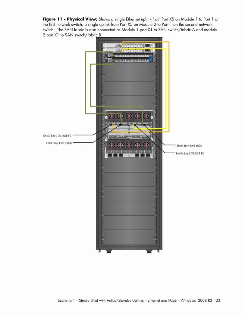
Figure 11 - Physical View; Shows a single Ethernet uplink from Port X5 on Module 1 to Port 1 on the first network switch, a single uplink from Port X5 on Module 2 to Port 1 on the second network switch. The SAN fabric is also connected as Module 1 port X1 to SAN switch/fabric A and module 2 port X1 to SAN switch/fabric B.
Scenario 1 – Simple vNet with Active/Standby Uplinks – Ethernet and FCoE – Windows 2008 R2 24
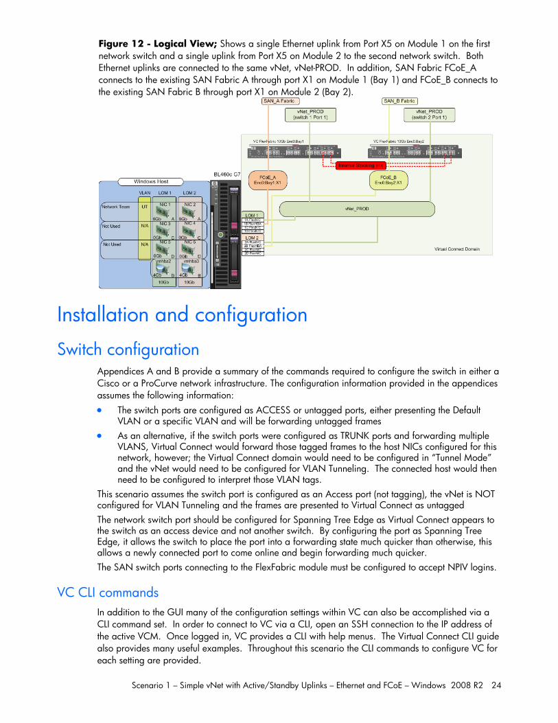
Figure 12 - Logical View; Shows a single Ethernet uplink from Port X5 on Module 1 on the first network switch and a single uplink from Port X5 on Module 2 to the second network switch. Both Ethernet uplinks are connected to the same vNet, vNet-PROD. In addition, SAN Fabric FCoE_A connects to the existing SAN Fabric A through port X1 on Module 1 (Bay 1) and FCoE_B connects to the existing SAN Fabric B through port X1 on Module 2 (Bay 2).
Installation and configuration
Switch configuration Appendices A and B provide a summary of the commands required to configure the switch in either a Cisco or a ProCurve network infrastructure. The configuration information provided in the appendices assumes the following information: The switch ports are configured as ACCESS or untagged ports, either presenting the Default
VLAN or a specific VLAN and will be forwarding untagged frames As an alternative, if the switch ports were configured as TRUNK ports and forwarding multiple
VLANS, Virtual Connect would forward those tagged frames to the host NICs configured for this network, however; the Virtual Connect domain would need to be configured in “Tunnel Mode” and the vNet would need to be configured for VLAN Tunneling. The connected host would then need to be configured to interpret those VLAN tags.
This scenario assumes the switch port is configured as an Access port (not tagging), the vNet is NOT configured for VLAN Tunneling and the frames are presented to Virtual Connect as untagged The network switch port should be configured for Spanning Tree Edge as Virtual Connect appears to the switch as an access device and not another switch. By configuring the port as Spanning Tree Edge, it allows the switch to place the port into a forwarding state much quicker than otherwise, this allows a newly connected port to come online and begin forwarding much quicker. The SAN switch ports connecting to the FlexFabric module must be configured to accept NPIV logins.
VC CLI commands In addition to the GUI many of the configuration settings within VC can also be accomplished via a CLI command set. In order to connect to VC via a CLI, open an SSH connection to the IP address of the active VCM. Once logged in, VC provides a CLI with help menus. The Virtual Connect CLI guide also provides many useful examples. Throughout this scenario the CLI commands to configure VC for each setting are provided.
Scenario 1 – Simple vNet with Active/Standby Uplinks – Ethernet and FCoE – Windows 2008 R2 25
Configuring the VC module Physically connect Port 1 of network switch 1 to Port X5 of the VC module in Bay 1 Physically connect Port 1 of network switch 2 to Port X5 of the VC module in Bay 2 Note: if you have only one network switch, connect VC port 1 (Bay 2) to an alternate port on the same switch. This will NOT create a network loop and Spanning Tree is not required. Physically connect Ports X1 on the FlexFabric module Bay 1 to switch ports in SAN Fabric A Physically connect Ports X1 on the FlexFabric module Bay 2 to switch ports in SAN Fabric B
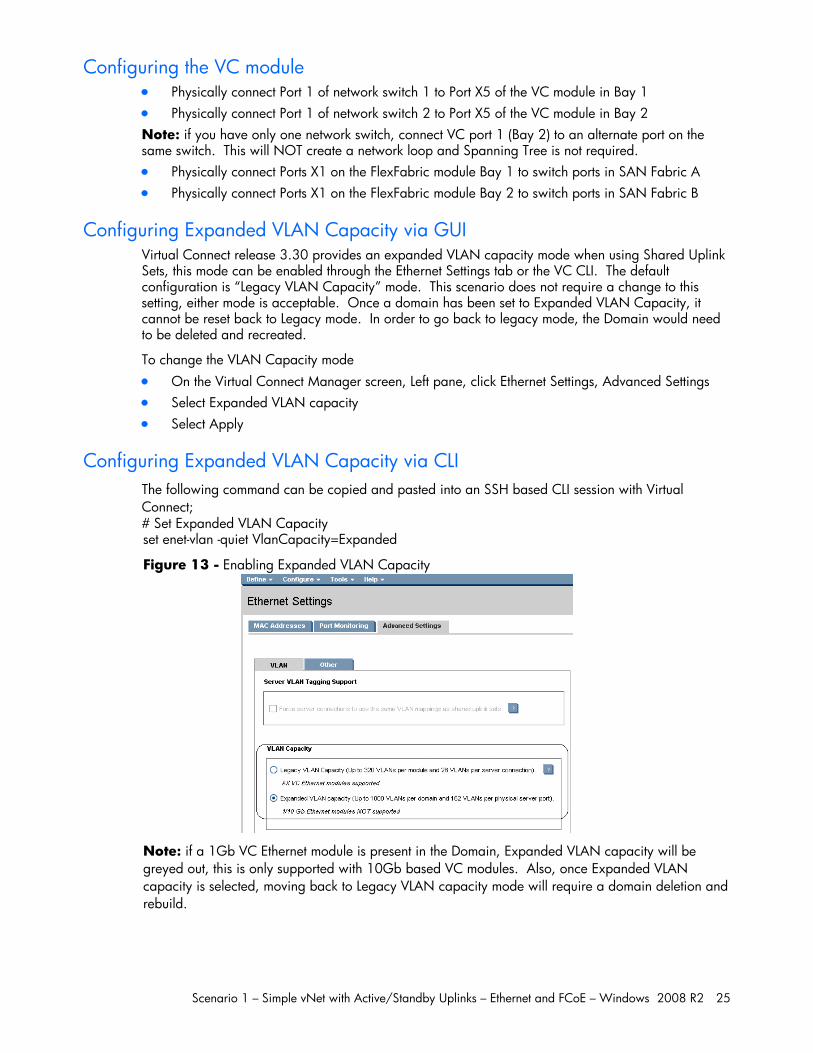
Configuring Expanded VLAN Capacity via GUI Virtual Connect release 3.30 provides an expanded VLAN capacity mode when using Shared Uplink Sets, this mode can be enabled through the Ethernet Settings tab or the VC CLI. The default configuration is “Legacy VLAN Capacity” mode. This scenario does not require a change to this setting, either mode is acceptable. Once a domain has been set to Expanded VLAN Capacity, it cannot be reset back to Legacy mode. In order to go back to legacy mode, the Domain would need to be deleted and recreated.
To change the VLAN Capacity mode On the Virtual Connect Manager screen, Left pane, click Ethernet Settings, Advanced Settings Select Expanded VLAN capacity Select Apply
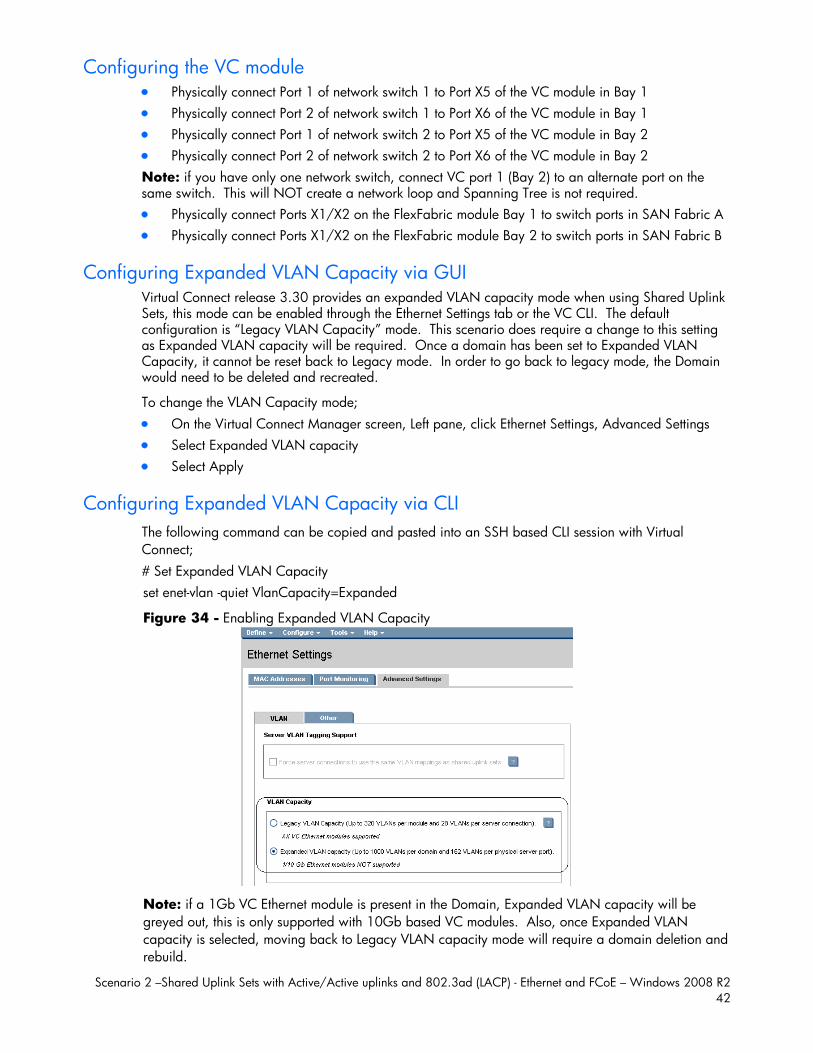
Configuring Expanded VLAN Capacity via CLI The following command can be copied and pasted into an SSH based CLI session with Virtual Connect; # Set Expanded VLAN Capacity set enet-vlan -quiet VlanCapacity=Expanded
Figure 13 - Enabling Expanded VLAN Capacity
Note: if a 1Gb VC Ethernet module is present in the Domain, Expanded VLAN capacity will be greyed out, this is only supported with 10Gb based VC modules. Also, once Expanded VLAN capacity is selected, moving back to Legacy VLAN capacity mode will require a domain deletion and rebuild.
Scenario 1 – Simple vNet with Active/Standby Uplinks – Ethernet and FCoE – Windows 2008 R2 26
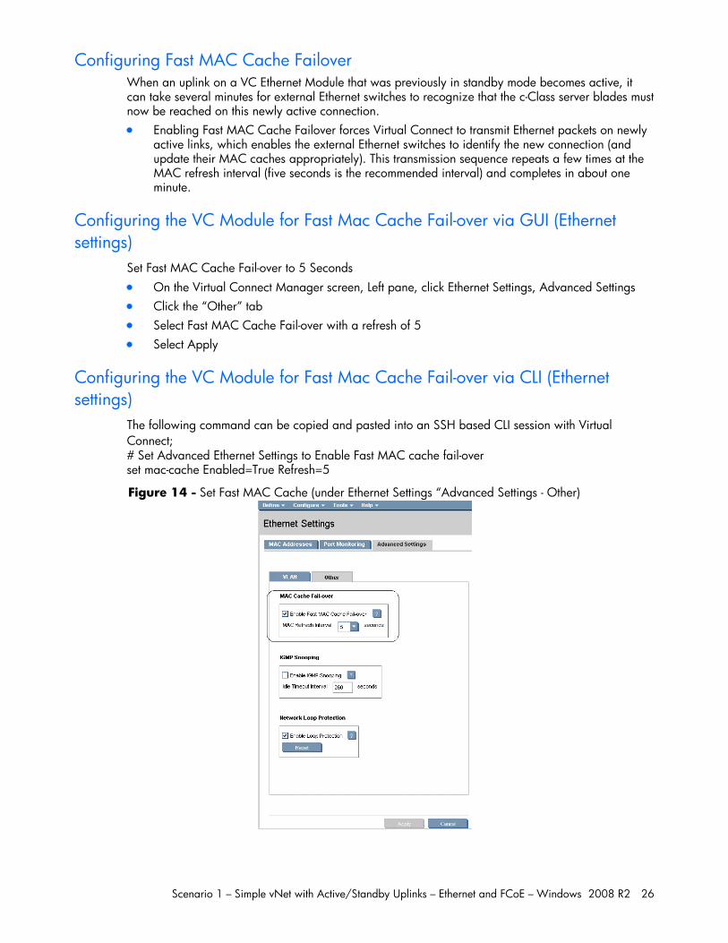
Configuring Fast MAC Cache Failover When an uplink on a VC Ethernet Module that was previously in standby mode becomes active, it can take several minutes for external Ethernet switches to recognize that the c-Class server blades must now be reached on this newly active connection. Enabling Fast MAC Cache Failover forces Virtual Connect to transmit Ethernet packets on newly
active links, which enables the external Ethernet switches to identify the new connection (and update their MAC caches appropriately). This transmission sequence repeats a few times at the MAC refresh interval (five seconds is the recommended interval) and completes in about one minute.
Configuring the VC Module for Fast Mac Cache Fail-over via GUI (Ethernet settings)
Set Fast MAC Cache Fail-over to 5 Seconds On the Virtual Connect Manager screen, Left pane, click Ethernet Settings, Advanced Settings Click the “Other” tab Select Fast MAC Cache Fail-over with a refresh of 5 Select Apply
Configuring the VC Module for Fast Mac Cache Fail-over via CLI (Ethernet settings)
The following command can be copied and pasted into an SSH based CLI session with Virtual Connect; # Set Advanced Ethernet Settings to Enable Fast MAC cache fail-over set mac-cache Enabled=True Refresh=5
Figure 14 - Set Fast MAC Cache (under Ethernet Settings “Advanced Settings - Other)
Scenario 1 – Simple vNet with Active/Standby Uplinks – Ethernet and FCoE – Windows 2008 R2 27
Defining a new vNet via GUI Create a vNet and name it “vNet-PROD” Login to Virtual Connect, if a Domain has not been created, create it now, but cancel out of the
configuration wizards after the domain has been created. On the Virtual Connect Manager screen, click Define, Ethernet Network to create a vNet Enter the Network Name of “vNet-PROD”
Note; Do NOT select any of the options (ie; Smart Link, Private Networks etc.) Select Add Port, then add the following ports;
Enclosure 1 (enc0), Bay 1, Port X5
Enclosure 1 (enc0), Bay 2, Port X5 Leave Connection Mode as Auto Select Apply
Note: By connecting TWO Uplinks from this vNet we have provided a redundant path to the network. As each uplink originates from a different VC module, one uplink will be Active and the second will be in Standby. This configuration provides the ability to loose an uplink cable, network switch or depending on how the NICs are configured at the server (teamed or un-teamed), even a VC module.
Note: Smart Link – In this configuration Smartlink should NOT be enabled. Smartlink is used to turn off downlink ports within Virtual Connect, if ALL available uplinks to a vNet are down. We will use Smartlink in a later scenario.
Also, notice the new “color” and “label” features within Virtual connect network configuration which were added to help identify networks.
Defining a new vNet via CLI The following command(s) can be copied and pasted into an SSH based CLI session with Virtual Connect # Create the vNet "vNet-PROD" and configure uplinks as discussed above add Network vNet-PROD add uplinkport enc0:1:X5 Network=vNet-PROD speed=auto add uplinkport enc0:2:X5 Network=vNet-PROD speed=auto set network vNet-PROD SmartLink=Disabled
Scenario 1 – Simple vNet with Active/Standby Uplinks – Ethernet and FCoE – Windows 2008 R2 28
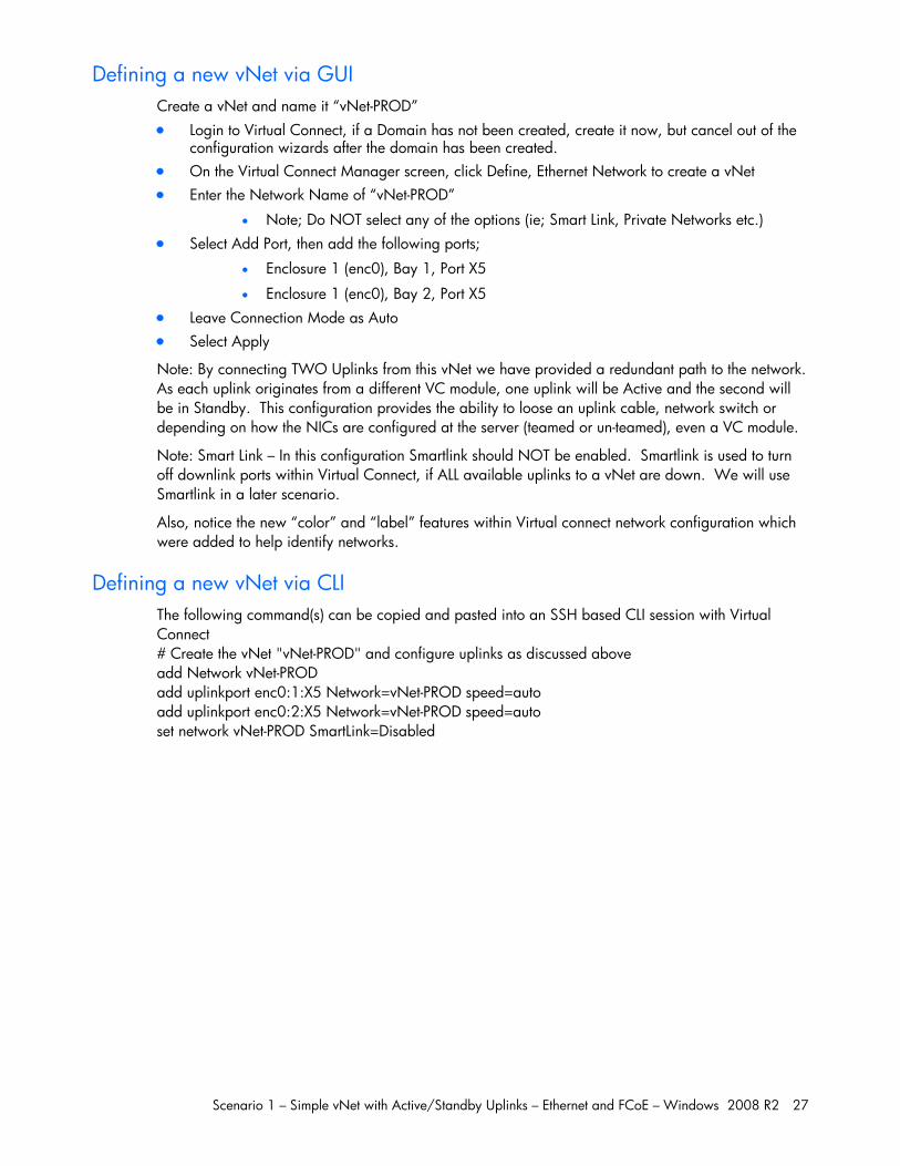
Figure 15 - Define Ethernet Network (vNet-PROD). Note: The Port Status and Connected to information. If the connected switch has LLDP enabled, the connected to information should be displayed as below
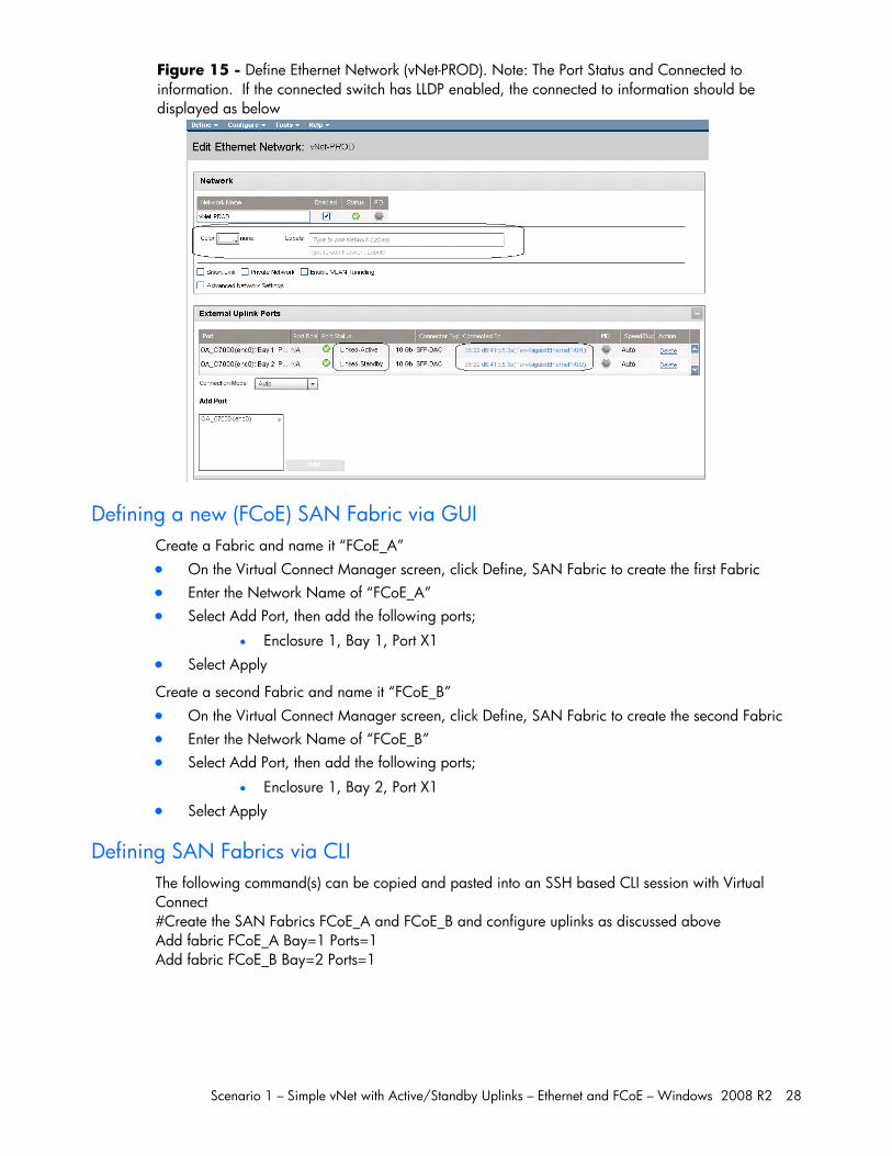
Defining a new (FCoE) SAN Fabric via GUI Create a Fabric and name it “FCoE_A” On the Virtual Connect Manager screen, click Define, SAN Fabric to create the first Fabric Enter the Network Name of “FCoE_A” Select Add Port, then add the following ports;
Enclosure 1, Bay 1, Port X1 Select Apply
Create a second Fabric and name it “FCoE_B” On the Virtual Connect Manager screen, click Define, SAN Fabric to create the second Fabric Enter the Network Name of “FCoE_B” Select Add Port, then add the following ports;
Enclosure 1, Bay 2, Port X1 Select Apply
Defining SAN Fabrics via CLI The following command(s) can be copied and pasted into an SSH based CLI session with Virtual Connect #Create the SAN Fabrics FCoE_A and FCoE_B and configure uplinks as discussed above Add fabric FCoE_A Bay=1 Ports=1 Add fabric FCoE_B Bay=2 Ports=1
Scenario 1 – Simple vNet with Active/Standby Uplinks – Ethernet and FCoE – Windows 2008 R2 29
Figure 16 - FCoE SAN fabrics configured with a single 8Gb uplink per fabric. Note the bay and port numbers on the right
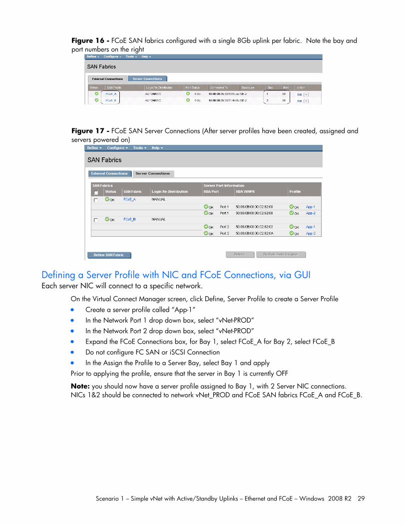
Figure 17 - FCoE SAN Server Connections (After server profiles have been created, assigned and servers powered on)
Defining a Server Profile with NIC and FCoE Connections, via GUI Each server NIC will connect to a specific network.
On the Virtual Connect Manager screen, click Define, Server Profile to create a Server Profile Create a server profile called “App-1” In the Network Port 1 drop down box, select “vNet-PROD” In the Network Port 2 drop down box, select “vNet-PROD” Expand the FCoE Connections box, for Bay 1, select FCoE_A for Bay 2, select FCoE_B Do not configure FC SAN or iSCSI Connection In the Assign the Profile to a Server Bay, select Bay 1 and apply Prior to applying the profile, ensure that the server in Bay 1 is currently OFF
Note: you should now have a server profile assigned to Bay 1, with 2 Server NIC connections. NICs 1&2 should be connected to network vNet_PROD and FCoE SAN fabrics FCoE_A and FCoE_B.
Scenario 1 – Simple vNet with Active/Standby Uplinks – Ethernet and FCoE – Windows 2008 R2 30
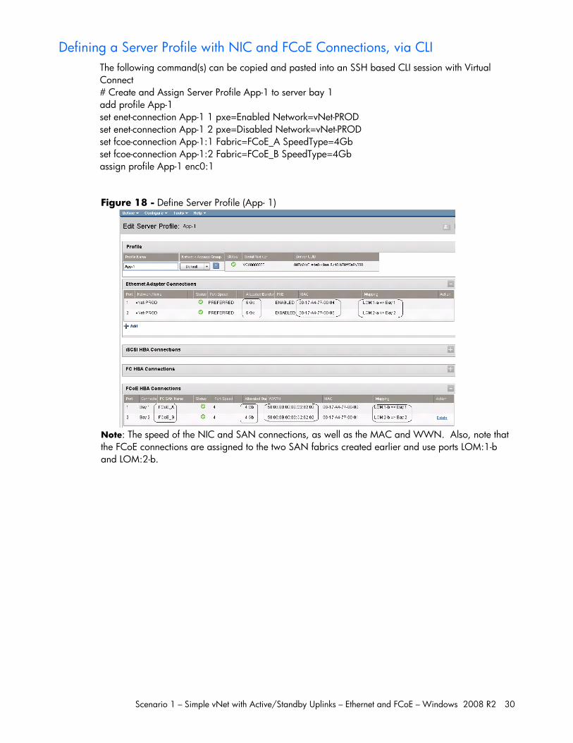
Defining a Server Profile with NIC and FCoE Connections, via CLI The following command(s) can be copied and pasted into an SSH based CLI session with Virtual Connect # Create and Assign Server Profile App-1 to server bay 1 add profile App-1 set enet-connection App-1 1 pxe=Enabled Network=vNet-PROD set enet-connection App-1 2 pxe=Disabled Network=vNet-PROD set fcoe-connection App-1:1 Fabric=FCoE_A SpeedType=4Gb set fcoe-connection App-1:2 Fabric=FCoE_B SpeedType=4Gb assign profile App-1 enc0:1
Figure 18 - Define Server Profile (App- 1)
Note: The speed of the NIC and SAN connections, as well as the MAC and WWN. Also, note that the FCoE connections are assigned to the two SAN fabrics created earlier and use ports LOM:1-b and LOM:2-b.
Scenario 1 – Simple vNet with Active/Standby Uplinks – Ethernet and FCoE – Windows 2008 R2 31
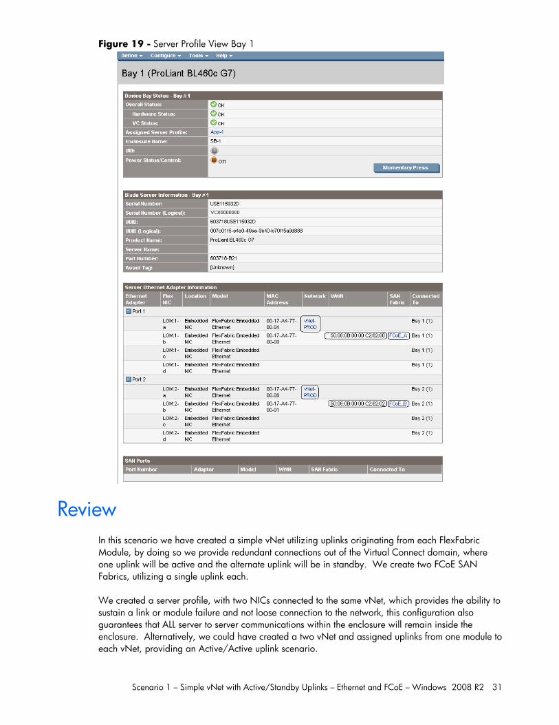
Figure 19 - Server Profile View Bay 1
Review
In this scenario we have created a simple vNet utilizing uplinks originating from each FlexFabric Module, by doing so we provide redundant connections out of the Virtual Connect domain, where one uplink will be active and the alternate uplink will be in standby. We create two FCoE SAN Fabrics, utilizing a single uplink each. We created a server profile, with two NICs connected to the same vNet, which provides the ability to sustain a link or module failure and not loose connection to the network, this configuration also guarantees that ALL server to server communications within the enclosure will remain inside the enclosure. Alternatively, we could have created a two vNet and assigned uplinks from one module to each vNet, providing an Active/Active uplink scenario.
Scenario 1 – Simple vNet with Active/Standby Uplinks – Ethernet and FCoE – Windows 2008 R2 32
The FCoE SAN fabric connects to each SAN fabric over a single uplink per module. Additional uplinks could be added to either the San fabrics or the Ethernet networks, which could increase performance and/or availability.
Results – Windows 2008 R2 Networking Examples We have successfully configured FlexFabric with a simple vNet and redundant SAN fabrics. We have created a server profile to connect to the vNet with TWO NICs and the SAN fabrics using the FCoE connections created within the profile.
Although both Ethernet and Fibre channel connectivity is provided by the CNA adapter used in the G7 servers; each capability (LAN and SAN) is provided by a different component of the adapter, they appear in the server as individual network and SAN adapters.
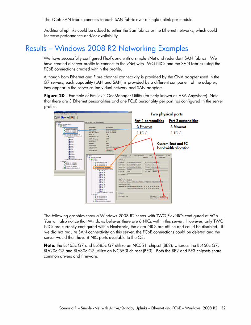
Figure 20 - Example of Emulex's OneManager Utility (formerly known as HBA Anywhere). Note that there are 3 Ethernet personalities and one FCoE personality per port, as configured in the server profile.
The following graphics show a Windows 2008 R2 server with TWO FlexNICs configured at 6Gb. You will also notice that Windows believes there are 6 NICs within this server. However, only TWO NICs are currently configured within FlexFabric, the extra NICs are offline and could be disabled. If we did not require SAN connectivity on this server, the FCoE connections could be deleted and the server would then have 8 NIC ports available to the OS.
Note: the BL465c G7 and BL685c G7 utilize an NC551i chipset (BE2), whereas the BL460c G7, BL620c G7 and BL680c G7 utilize an NC553i chipset (BE3). Both the BE2 and BE3 chipsets share common drivers and firmware.
Scenario 1 – Simple vNet with Active/Standby Uplinks – Ethernet and FCoE – Windows 2008 R2 33
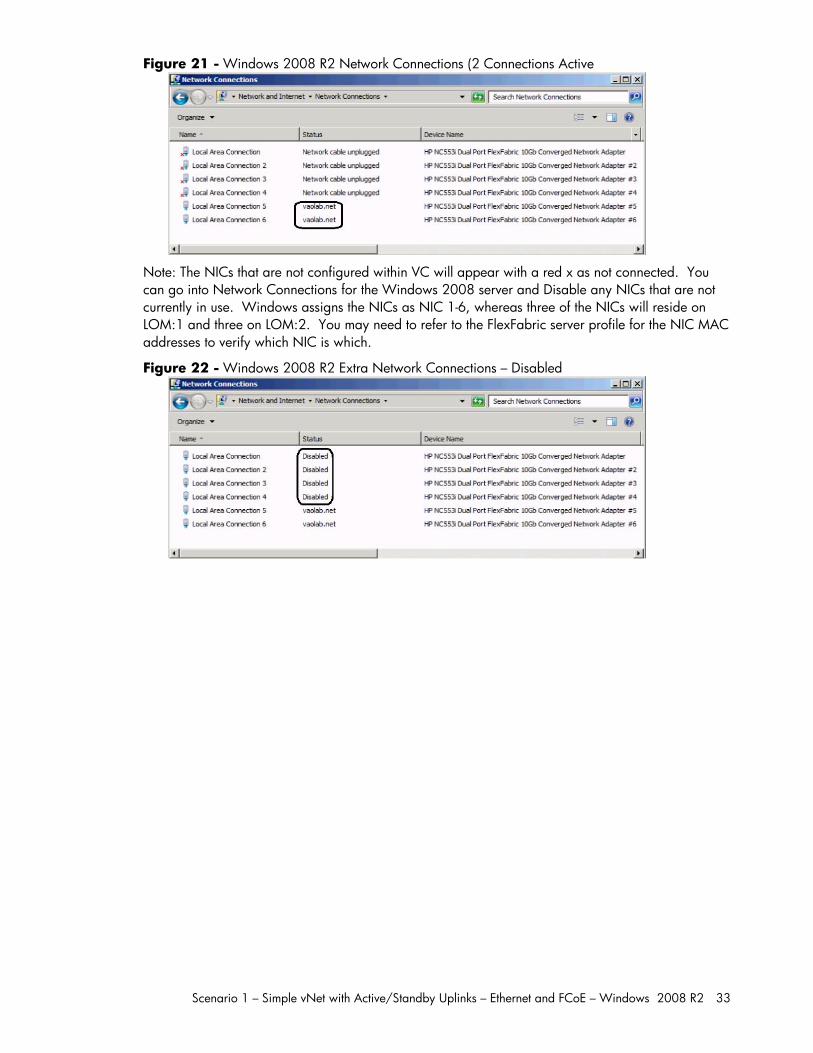
Figure 21 - Windows 2008 R2 Network Connections (2 Connections Active
Note: The NICs that are not configured within VC will appear with a red x as not connected. You can go into Network Connections for the Windows 2008 server and Disable any NICs that are not currently in use. Windows assigns the NICs as NIC 1-6, whereas three of the NICs will reside on LOM:1 and three on LOM:2. You may need to refer to the FlexFabric server profile for the NIC MAC addresses to verify which NIC is which.
Figure 22 - Windows 2008 R2 Extra Network Connections – Disabled
Scenario 1 – Simple vNet with Active/Standby Uplinks – Ethernet and FCoE – Windows 2008 R2 34
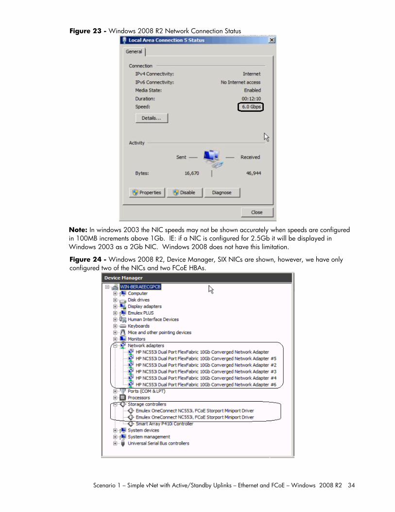
Figure 23 - Windows 2008 R2 Network Connection Status
Note: In windows 2003 the NIC speeds may not be shown accurately when speeds are configured in 100MB increments above 1Gb. IE: if a NIC is configured for 2.5Gb it will be displayed in Windows 2003 as a 2Gb NIC. Windows 2008 does not have this limitation.
Figure 24 - Windows 2008 R2, Device Manager, SIX NICs are shown, however, we have only configured two of the NICs and two FCoE HBAs.
Scenario 1 – Simple vNet with Active/Standby Uplinks – Ethernet and FCoE – Windows 2008 R2 35
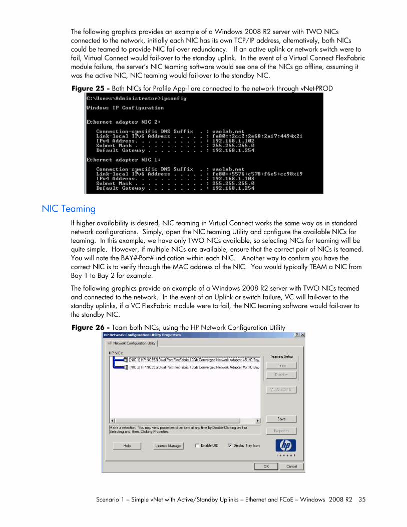
The following graphics provides an example of a Windows 2008 R2 server with TWO NICs connected to the network, initially each NIC has its own TCP/IP address, alternatively, both NICs could be teamed to provide NIC fail-over redundancy. If an active uplink or network switch were to fail, Virtual Connect would fail-over to the standby uplink. In the event of a Virtual Connect FlexFabric module failure, the server’s NIC teaming software would see one of the NICs go offline, assuming it was the active NIC, NIC teaming would fail-over to the standby NIC.
Figure 25 - Both NICs for Profile App-1are connected to the network through vNet-PROD
NIC Teaming If higher availability is desired, NIC teaming in Virtual Connect works the same way as in standard network configurations. Simply, open the NIC teaming Utility and configure the available NICs for teaming. In this example, we have only TWO NICs available, so selecting NICs for teaming will be quite simple. However, if multiple NICs are available, ensure that the correct pair of NICs is teamed. You will note the BAY#-Port# indication within each NIC. Another way to confirm you have the correct NIC is to verify through the MAC address of the NIC. You would typically TEAM a NIC from Bay 1 to Bay 2 for example.
The following graphics provide an example of a Windows 2008 R2 server with TWO NICs teamed and connected to the network. In the event of an Uplink or switch failure, VC will fail-over to the standby uplinks, if a VC FlexFabric module were to fail, the NIC teaming software would fail-over to the standby NIC.
Figure 26 - Team both NICs, using the HP Network Configuration Utility
Scenario 1 – Simple vNet with Active/Standby Uplinks – Ethernet and FCoE – Windows 2008 R2 36
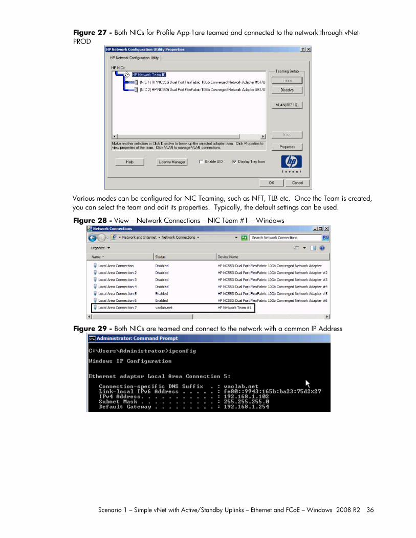
Figure 27 - Both NICs for Profile App-1are teamed and connected to the network through vNet-PROD
Various modes can be configured for NIC Teaming, such as NFT, TLB etc. Once the Team is created, you can select the team and edit its properties. Typically, the default settings can be used.
Figure 28 - View – Network Connections – NIC Team #1 – Windows
Figure 29 - Both NICs are teamed and connect to the network with a common IP Address
Scenario 1 – Simple vNet with Active/Standby Uplinks – Ethernet and FCoE – Windows 2008 R2 37
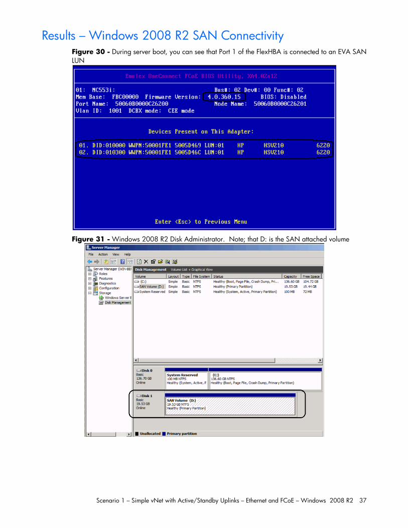
Results – Windows 2008 R2 SAN Connectivity Figure 30 - During server boot, you can see that Port 1 of the FlexHBA is connected to an EVA SAN LUN
Figure 31 - Windows 2008 R2 Disk Administrator. Note; that D: is the SAN attached volume
Scenario 1 – Simple vNet with Active/Standby Uplinks – Ethernet and FCoE – Windows 2008 R2 38
Summary We presented a Virtual Connect Network scenario by creating a simple vNet, we included a dual path SAN fabric for storage connectivity.
When VC profile App-1 is applied to the server in bay1 and is powered up, it has one NIC connected through each FlexFabric module connected to “vNet-PROD”, which connects to the network infrastructure through the 10Gb uplinks. These NICs could now be configured as individual NICs with their own IP address or as a pair of TEAMED NICs. Either NIC could be active. As a result, this server could access the network through either NIC or either uplink cable, depending on which is active at the time. Each NIC is configured for 6Gb of network bandwidth and each FCoE port is configured for 4Gb of SAN bandwidth.
Additional NICs could be added within FlexFabric, by simply powering the server off and adding up to a total of 6 NICs, the NIC speed can then be adjusted accordingly to suit the needs of each NIC. If additional or less SAN bandwidth is required, the speed of the SAN connection can also be adjusted.
As additional servers are added to the enclosure, simply create additional profiles, or copy existing profiles, configure the NICs for LAN and SAN fabrics as required and apply them to the appropriate server bays and power the server on.
Scenario 2 –Shared Uplink Sets with Active/Active uplinks and 802.3ad (LACP) - Ethernet and FCoE – Windows 2008 R2 39
Scenario 2 –Shared Uplink Sets with Active/Active uplinks and 802.3ad (LACP) - Ethernet and FCoE – Windows 2008 R2
Overview This scenario will implement the Shared Uplink Set (SUS) to provide support for multiple VLANs. Virtual connect 3.30 increased the number of VLANs supported on a Shared Uplink Set and provides some enhanced GUI features that reduce the effort required to create large number of VLANs.
In this scenario, the upstream network switches connect to each FlexFabric module and two separate Shared Uplink Sets, providing an Active/Active configuration, LACP will be used to aggregate those links.
As multiple VLANs will be supported in this configuration, the upstream switch ports connecting to the FlexFabric modules will be configured to properly present those VLANs. In this scenario, the upstream switch ports will be configured for VLAN trunking/VLAN tagging.
When configuring Virtual Connect, we can provide several ways to implement network fail-over or redundancy. One option would be to connect TWO uplinks to a single virtual connect network; those two uplinks would connect from different Virtual Connect modules within the enclosure and could then connect to the same upstream switch or two different upstream switches, depending on your redundancy needs. An alternative would be to configure TWO separate Virtual Connect networks, each with a single, or multiple, uplinks configured. Each option has its advantages and disadvantages. For example; an Active/Standby configuration places the redundancy at the VC level, where Active/Active places it at the OS NIC teaming or bonding level. We will review the first option in this scenario. We will review the second option in this scenario.
In addition, several Virtual Connect Networks can be configured to support the required networks to the servers within the BladeSystem enclosure. These networks could be used to separate the various network traffic types, such as iSCSI, backup and VMotion from production network traffic.
This scenario will also leverage the Fibre Channel over Ethernet (FCoE) capabilities of the FlexFabric modules. Each Fibre channel fabric will have two uplinks connected to each of the FlexFabric modules.
Requirements This scenario will support both Ethernet and fibre channel connectivity. In order to implement this scenario, an HP BladeSystem c7000 enclosure with one or more server blades and TWO Virtual Connect FlexFabric modules, installed in I/O Bays 1& 2 are required. In addition, we will require ONE or TWO external Network switches. As Virtual Connect does not appear to the network as a switch and is transparent to the network, any standard managed switch will work with Virtual Connect. The Fibre Channel uplinks will connect to the existing FC SAN fabrics. The SAN switch ports will need to be configured to support NPIV logins. Two uplinks from each FlexFabric module will be connected to the existing SAN fabrics.

Scenario 2 –S
Fig1 aPortTWFab
Shared Uplink S
ure 32 - Phynd 2 on the fits 1 and 2 on
WO uplinks perbric B
Sets with Active
ysical View; Sirst network sw the second nr fabric, from
e/Active uplink
Shows two Ethwitch and twonetwork switch ports X1 and
ks and 802.3ad
hernet uplinks o Ethernet uplih. The SAN fa X2 on modul
d (LACP) - Ether
from Ports X5inks from Portabrics are alsle 1 to Fabric
rnet and FCoE
5 and X6 on Mts X5 and X6 so connected A and ports
– Windows 20
Module 1 to Pon Module 2 redundantly, X1 and X2 to
008 R2 40
Ports to with
o
Scenario 2 –Shared Uplink Sets with Active/Active uplinks and 802.3ad (LACP) - Ethernet and FCoE – Windows 2008 R2 41
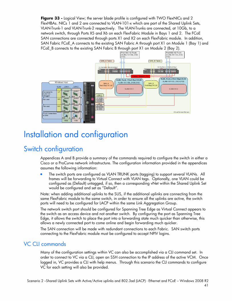
Figure 33 - Logical View; the server blade profile is configured with TWO FlexNICs and 2 FlexHBAs. NICs 1 and 2 are connected to VLAN-101-x which are part of the Shared Uplink Sets, VLAN-Trunk-1 and VLAN-Trunk-2 respectively. The VLAN-Trunks are connected, at 10Gb, to a network switch, through Ports X5 and X6 on each FlexFabric Module in Bays 1 and 2. The FCoE SAN connections are connected through ports X1 and X2 on each FlexFabric module. In addition, SAN Fabric FCoE_A connects to the existing SAN Fabric A through port X1 on Module 1 (Bay 1) and FCoE_B connects to the existing SAN Fabric B through port X1 on Module 2 (Bay 2).
Installation and configuration
Switch configuration Appendices A and B provide a summary of the commands required to configure the switch in either a Cisco or a ProCurve network infrastructure. The configuration information provided in the appendices assumes the following information: The switch ports are configured as VLAN TRUNK ports (tagging) to support several VLANs. All
frames will be forwarding to Virtual Connect with VLAN tags. Optionally, one VLAN could be configured as (Default) untagged, if so, then a corresponding vNet within the Shared Uplink Set would be configured and set as “Default”.
Note: when adding additional uplinks to the SUS, if the additional uplinks are connecting from the same FlexFabric module to the same switch, in order to ensure all the uplinks are active, the switch ports will need to be configured for LACP within the same Link Aggregation Group. The network switch port should be configured for Spanning Tree Edge as Virtual Connect appears to the switch as an access device and not another switch. By configuring the port as Spanning Tree Edge, it allows the switch to place the port into a forwarding state much quicker than otherwise, this allows a newly connected port to come online and begin forwarding much quicker. The SAN connection will be made with redundant connections to each Fabric. SAN switch ports connecting to the FlexFabric module must be configured to accept NPIV logins.
VC CLI commands Many of the configuration settings within VC can also be accomplished via a CLI command set. In order to connect to VC via a CLI, open an SSH connection to the IP address of the active VCM. Once logged in, VC provides a CLI with help menus. Through this scenario the CLI commands to configure VC for each setting will also be provided.
Scenario 2 –Shared Uplink Sets with Active/Active uplinks and 802.3ad (LACP) - Ethernet and FCoE – Windows 2008 R2 42
Configuring the VC module Physically connect Port 1 of network switch 1 to Port X5 of the VC module in Bay 1 Physically connect Port 2 of network switch 1 to Port X6 of the VC module in Bay 1 Physically connect Port 1 of network switch 2 to Port X5 of the VC module in Bay 2 Physically connect Port 2 of network switch 2 to Port X6 of the VC module in Bay 2 Note: if you have only one network switch, connect VC port 1 (Bay 2) to an alternate port on the same switch. This will NOT create a network loop and Spanning Tree is not required. Physically connect Ports X1/X2 on the FlexFabric module Bay 1 to switch ports in SAN Fabric A Physically connect Ports X1/X2 on the FlexFabric module Bay 2 to switch ports in SAN Fabric B
Configuring Expanded VLAN Capacity via GUI Virtual Connect release 3.30 provides an expanded VLAN capacity mode when using Shared Uplink Sets, this mode can be enabled through the Ethernet Settings tab or the VC CLI. The default configuration is “Legacy VLAN Capacity” mode. This scenario does require a change to this setting as Expanded VLAN capacity will be required. Once a domain has been set to Expanded VLAN Capacity, it cannot be reset back to Legacy mode. In order to go back to legacy mode, the Domain would need to be deleted and recreated.
To change the VLAN Capacity mode; On the Virtual Connect Manager screen, Left pane, click Ethernet Settings, Advanced Settings Select Expanded VLAN capacity Select Apply
Configuring Expanded VLAN Capacity via CLI The following command can be copied and pasted into an SSH based CLI session with Virtual Connect; # Set Expanded VLAN Capacity set enet-vlan -quiet VlanCapacity=Expanded
Figure 34 - Enabling Expanded VLAN Capacity
Note: if a 1Gb VC Ethernet module is present in the Domain, Expanded VLAN capacity will be greyed out, this is only supported with 10Gb based VC modules. Also, once Expanded VLAN capacity is selected, moving back to Legacy VLAN capacity mode will require a domain deletion and rebuild.
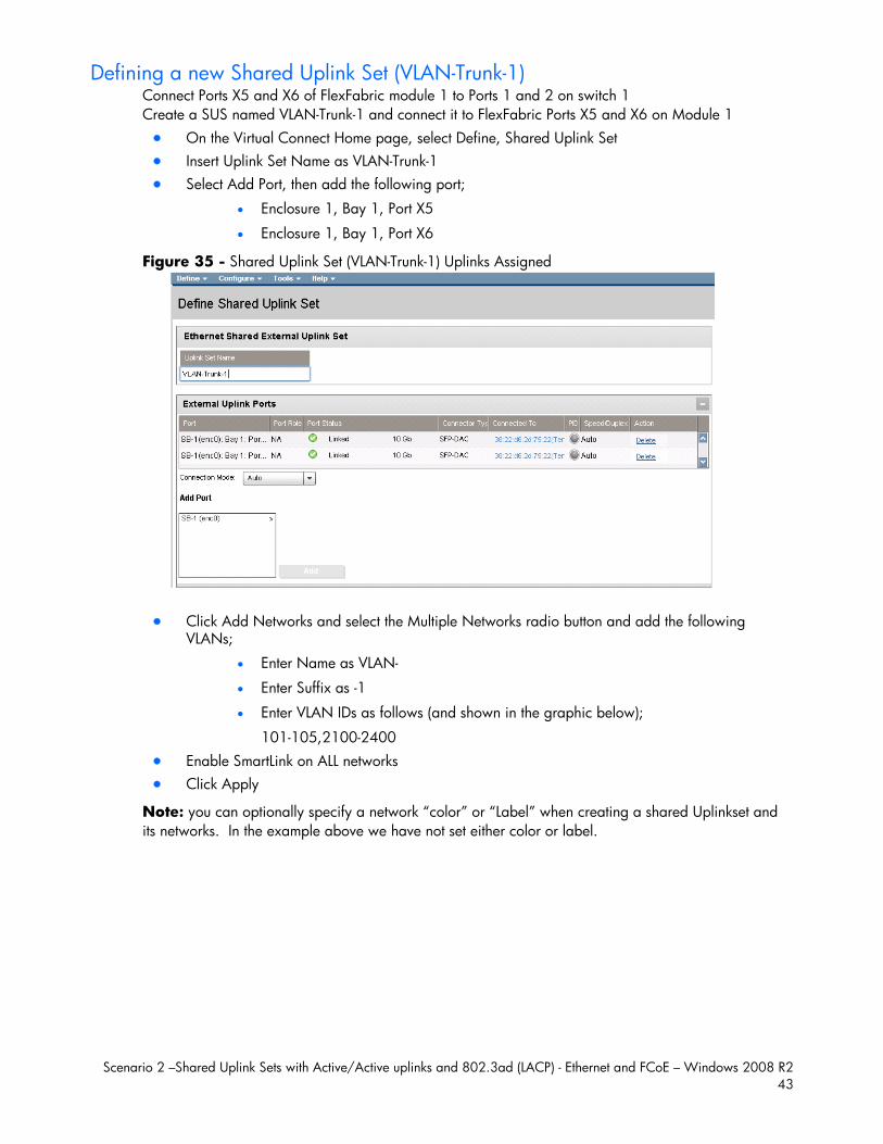
Scenario 2 –Shared Uplink Sets with Active/Active uplinks and 802.3ad (LACP) - Ethernet and FCoE – Windows 2008 R2 43
Defining a new Shared Uplink Set (VLAN-Trunk-1) Connect Ports X5 and X6 of FlexFabric module 1 to Ports 1 and 2 on switch 1 Create a SUS named VLAN-Trunk-1 and connect it to FlexFabric Ports X5 and X6 on Module 1 On the Virtual Connect Home page, select Define, Shared Uplink Set Insert Uplink Set Name as VLAN-Trunk-1 Select Add Port, then add the following port;
Enclosure 1, Bay 1, Port X5
Enclosure 1, Bay 1, Port X6
Figure 35 - Shared Uplink Set (VLAN-Trunk-1) Uplinks Assigned
Click Add Networks and select the Multiple Networks radio button and add the following VLANs;
Enter Name as VLAN-
Enter Suffix as -1
Enter VLAN IDs as follows (and shown in the graphic below);
101-105,2100-2400 Enable SmartLink on ALL networks Click Apply
Note: you can optionally specify a network “color” or “Label” when creating a shared Uplinkset and its networks. In the example above we have not set either color or label.
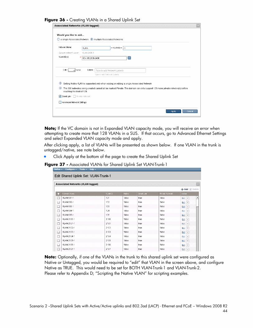
Scenario 2 –Shared Uplink Sets with Active/Active uplinks and 802.3ad (LACP) - Ethernet and FCoE – Windows 2008 R2 44
Figure 36 - Creating VLANs in a Shared Uplink Set
Note; If the VC domain is not in Expanded VLAN capacity mode, you will receive an error when attempting to create more that 128 VLANs in a SUS. If that occurs, go to Advanced Ethernet Settings and select Expanded VLAN capacity mode and apply. After clicking apply, a list of VLANs will be presented as shown below. If one VLAN in the trunk is untagged/native, see note below. Click Apply at the bottom of the page to create the Shared Uplink Set
Figure 37 - Associated VLANs for Shared Uplink Set VLAN-Trunk-1
Note: Optionally, if one of the VLANs in the trunk to this shared uplink set were configured as Native or Untagged, you would be required to “edit” that VLAN in the screen above, and configure Native as TRUE. This would need to be set for BOTH VLAN-Trunk-1 and VLAN-Trunk-2. Please refer to Appendix D; “Scripting the Native VLAN” for scripting examples.
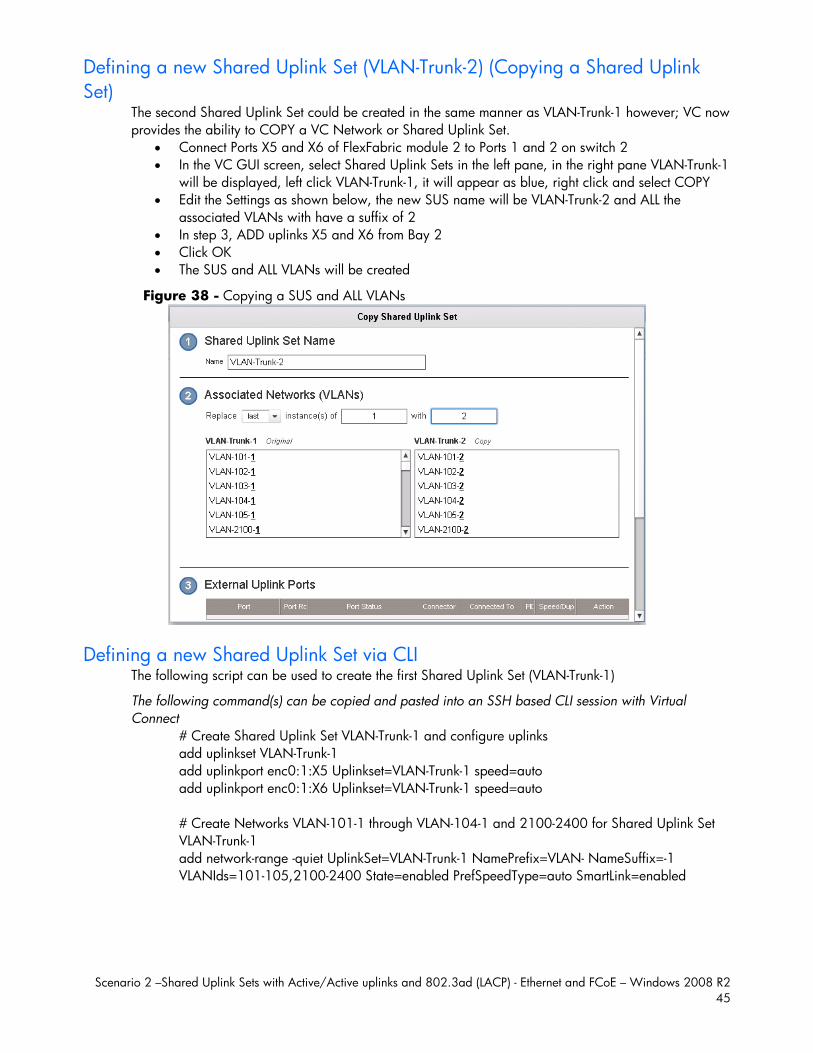
Scenario 2 –Shared Uplink Sets with Active/Active uplinks and 802.3ad (LACP) - Ethernet and FCoE – Windows 2008 R2 45
Defining a new Shared Uplink Set (VLAN-Trunk-2) (Copying a Shared Uplink Set)
The second Shared Uplink Set could be created in the same manner as VLAN-Trunk-1 however; VC now provides the ability to COPY a VC Network or Shared Uplink Set.
Connect Ports X5 and X6 of FlexFabric module 2 to Ports 1 and 2 on switch 2 In the VC GUI screen, select Shared Uplink Sets in the left pane, in the right pane VLAN-Trunk-1
will be displayed, left click VLAN-Trunk-1, it will appear as blue, right click and select COPY Edit the Settings as shown below, the new SUS name will be VLAN-Trunk-2 and ALL the
associated VLANs with have a suffix of 2 In step 3, ADD uplinks X5 and X6 from Bay 2 Click OK The SUS and ALL VLANs will be created
Figure 38 - Copying a SUS and ALL VLANs
Defining a new Shared Uplink Set via CLI The following script can be used to create the first Shared Uplink Set (VLAN-Trunk-1)
The following command(s) can be copied and pasted into an SSH based CLI session with Virtual Connect
# Create Shared Uplink Set VLAN-Trunk-1 and configure uplinks add uplinkset VLAN-Trunk-1 add uplinkport enc0:1:X5 Uplinkset=VLAN-Trunk-1 speed=auto add uplinkport enc0:1:X6 Uplinkset=VLAN-Trunk-1 speed=auto # Create Networks VLAN-101-1 through VLAN-104-1 and 2100-2400 for Shared Uplink Set VLAN-Trunk-1 add network-range -quiet UplinkSet=VLAN-Trunk-1 NamePrefix=VLAN- NameSuffix=-1 VLANIds=101-105,2100-2400 State=enabled PrefSpeedType=auto SmartLink=enabled

Scenario 2 –Shared Uplink Sets with Active/Active uplinks and 802.3ad (LACP) - Ethernet and FCoE – Windows 2008 R2 46
The following script can be used to create the Second Shared Uplink Set (VLAN-Trunk-2) # Create Shared Uplink Set VLAN-Trunk-2 and configure uplinks add uplinkset VLAN-Trunk-2 add uplinkport enc0:2:X5 Uplinkset=VLAN-Trunk-2 speed=auto add uplinkport enc0:2:X6 Uplinkset=VLAN-Trunk-2 speed=auto # Create Networks VLAN101-2 through VLAN105-2 and VLAN-2100-2 through VLAN-2400-2 for Shared Uplink Set VLAN-Trunk-2 add network-range -quiet UplinkSet=VLAN-Trunk-2 NamePrefix=VLAN- NameSuffix=-2 VLANIds=101-105,2100-2400 State=enabled PrefSpeedType=auto SmartLink=enabled
Summary Note: In this scenario we have created two independent Share Uplink Sets (SUS), each originating from the opposite FlexFabric Modules, by doing so we provide the ability to create separate and redundant connections out of the Virtual Connect domain. When we create the server profiles, you will see how the NICs will connect to VLANs accessed through the opposite VC module, which provides the ability to create an Active / Active uplink scenario. Alternatively, we could have created a single SUS and assigned both sets of these uplink ports to the same SUS, however, this would have provided an Active/Standby uplink scenario, as shown in Scenario 5.
Defining a new (FCoE) SAN Fabric via GUI Create a Fabric and name it “FCoE_A” On the Virtual Connect Manager screen, click Define, SAN Fabric to create the first Fabric Enter the Network Name of “FCoE_A” Select Add Port, then add the following ports;
Enclosure 1, Bay 1, Port X1 Enclosure 1, Bay 1, Port X2
Select the Advanced Settings Select Automatic Login Re-Distribution
Select Apply
Create a second Fabric and name it “FCoE_B” On the Virtual Connect Manager screen, click Define, SAN Fabric to create the second Fabric Enter the Network Name of “FCoE_B” Select Add Port, then add the following ports;
Enclosure 1, Bay 2, Port X1 Enclosure 1, Bay 2, Port X2
Select the Advanced Settings Select Automatic Login Re-Distribution
Select Apply
Defining SAN Fabrics via CLI The following command(s) can be copied and pasted into an SSH based CLI session with Virtual Connect #Create the SAN Fabrics FCoE_A and FCoE_B and configure uplinks as discussed above Add fabric FCoE_A Bay=1 Ports=1,2 LinkDist=Auto Add fabric FCoE_B Bay=2 Ports=1,2 LinkDist=Auto
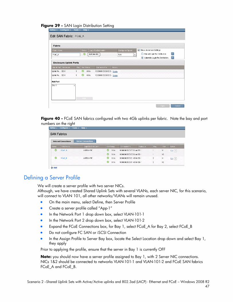
Scenario 2 –Shared Uplink Sets with Active/Active uplinks and 802.3ad (LACP) - Ethernet and FCoE – Windows 2008 R2 47
Figure 39 - SAN Login Distribution Setting
Figure 40 - FCoE SAN fabrics configured with two 4Gb uplinks per fabric. Note the bay and port numbers on the right
Defining a Server Profile We will create a server profile with two server NICs. Although, we have created Shared Uplink Sets with several VLANs, each server NIC, for this scenario, will connect to VLAN 101, all other networks/VLANs will remain unused. On the main menu, select Define, then Server Profile Create a server profile called “App-1” In the Network Port 1 drop down box, select VLAN-101-1 In the Network Port 2 drop down box, select VLAN-101-2 Expand the FCoE Connections box, for Bay 1, select FCoE_A for Bay 2, select FCoE_B Do not configure FC SAN or iSCSI Connection In the Assign Profile to Server Bay box, locate the Select Location drop down and select Bay 1,
they apply Prior to applying the profile, ensure that the server in Bay 1 is currently OFF
Note: you should now have a server profile assigned to Bay 1, with 2 Server NIC connections. NICs 1&2 should be connected to networks VLAN-101-1 and VLAN-101-2 and FCoE SAN fabrics FCoE_A and FCoE_B.
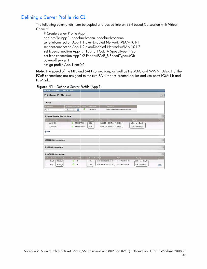
D
Scenario 2 –S
Defining aThe Con
NotFCoLOM
Fig
Shared Uplink S
a Server P following comnnect
# Create Seadd profile Aset enet-connset enet-connset fcoe-conset fcoe-conpoweroff seassign profi
te: The speed oE connectionsM:2-b.
ure 41 - Def
Sets with Active
rofile via mmand(s) can
erver Profile AApp-1 -nodefanection App-1nection App-1nection App-1nection App-1rver 1 le App-1 enc0
of the NIC ans are assigned
fine a Server
e/Active uplink
CLI n be copied a
App-1 aultfcconn -no1 1 pxe=Enab1 2 pxe=Disab1:1 Fabric=FC1:2 Fabric=FC
0:1
nd SAN connd to the two S
Profile (App-1
ks and 802.3ad
nd pasted into
odefaultfcoecobled Network=bled NetworkCoE_A SpeedCoE_B SpeedT
nections, as wSAN fabrics c
1)
d (LACP) - Ether
o an SSH bas
onn =VLAN-101-1k=VLAN-101-2dType=4Gb Type=4Gb
well as the MAreated earlier
rnet and FCoE
sed CLI sessio
2
AC and WWNr and use por
– Windows 20
on with Virtual
N. Also, that ts LOM:1-b a
008 R2 48
l
the nd
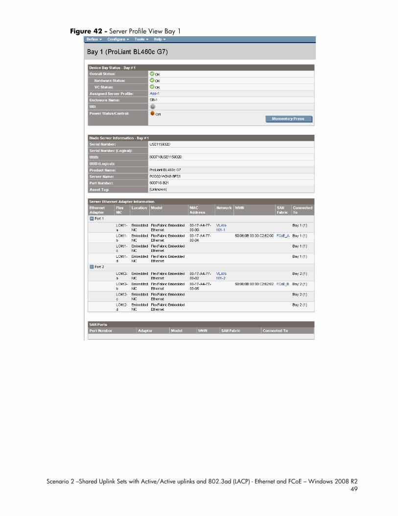
Scenario 2 –Shared Uplink Sets with Active/Active uplinks and 802.3ad (LACP) - Ethernet and FCoE – Windows 2008 R2 49
Figure 42 - Server Profile View Bay 1
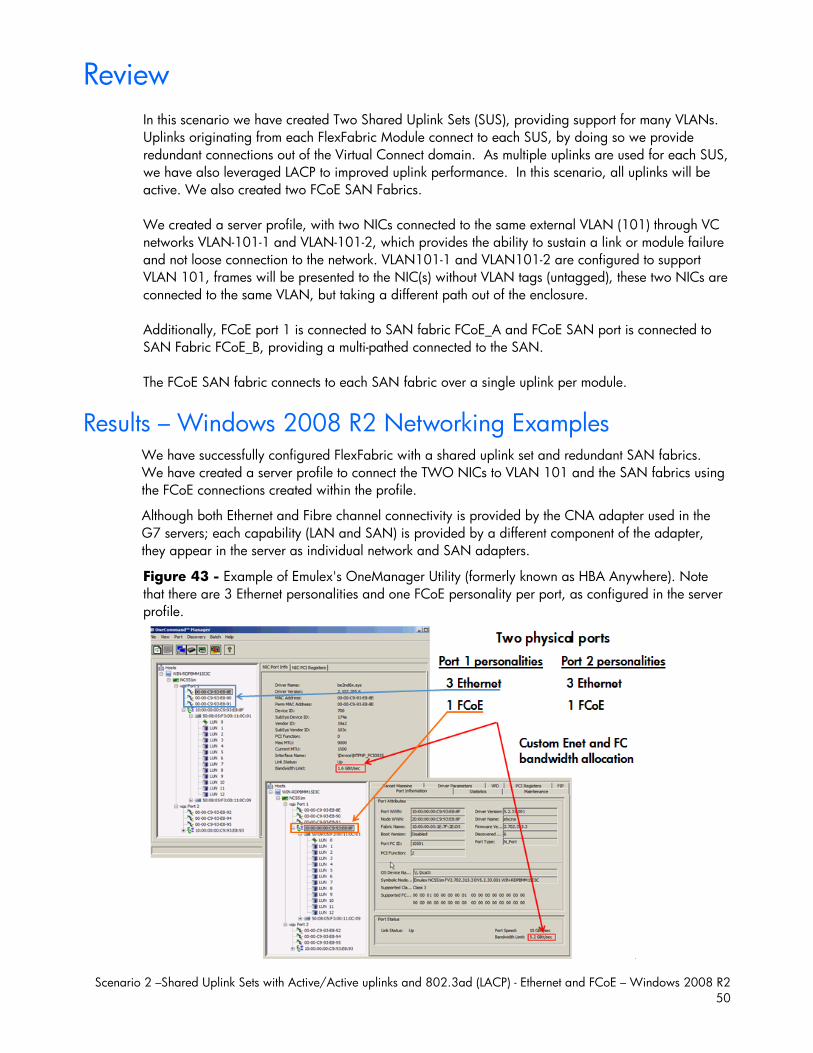
Scenario 2 –Shared Uplink Sets with Active/Active uplinks and 802.3ad (LACP) - Ethernet and FCoE – Windows 2008 R2 50
Review
In this scenario we have created Two Shared Uplink Sets (SUS), providing support for many VLANs. Uplinks originating from each FlexFabric Module connect to each SUS, by doing so we provide redundant connections out of the Virtual Connect domain. As multiple uplinks are used for each SUS, we have also leveraged LACP to improved uplink performance. In this scenario, all uplinks will be active. We also created two FCoE SAN Fabrics. We created a server profile, with two NICs connected to the same external VLAN (101) through VC networks VLAN-101-1 and VLAN-101-2, which provides the ability to sustain a link or module failure and not loose connection to the network. VLAN101-1 and VLAN101-2 are configured to support VLAN 101, frames will be presented to the NIC(s) without VLAN tags (untagged), these two NICs are connected to the same VLAN, but taking a different path out of the enclosure. Additionally, FCoE port 1 is connected to SAN fabric FCoE_A and FCoE SAN port is connected to SAN Fabric FCoE_B, providing a multi-pathed connected to the SAN. The FCoE SAN fabric connects to each SAN fabric over a single uplink per module.
Results – Windows 2008 R2 Networking Examples We have successfully configured FlexFabric with a shared uplink set and redundant SAN fabrics. We have created a server profile to connect the TWO NICs to VLAN 101 and the SAN fabrics using the FCoE connections created within the profile.
Although both Ethernet and Fibre channel connectivity is provided by the CNA adapter used in the G7 servers; each capability (LAN and SAN) is provided by a different component of the adapter, they appear in the server as individual network and SAN adapters.
Figure 43 - Example of Emulex's OneManager Utility (formerly known as HBA Anywhere). Note that there are 3 Ethernet personalities and one FCoE personality per port, as configured in the server profile.

Scenario 2 –Shared Uplink Sets with Active/Active uplinks and 802.3ad (LACP) - Ethernet and FCoE – Windows 2008 R2 51
The following graphics show a Windows 2008 R2 server with TWO FlexNICs configured at 6Gb. You will also notice that Windows believes there are 6 NICs within this server. However, only TWO NICs are currently configured within FlexFabric, the extra NICs are offline and could be disabled. If we did not require SAN connectivity on this server, the FCoE connections could be deleted and the server would then have 8 NIC ports available to the OS.
Note: the BL465c G7 and BL685c G7 utilize an NC551i chipset (BE2), whereas the BL460c G7, BL620c G7 and BL680c G7 utilize an NC553i chipset (BE3). Both the BE2 and BE3 chipsets share common drivers and firmware.
Figure 44 - Windows 2008 R2 Network Connections (2 Connections Active)
Note: The NICs that are not configured within VC will appear with a red x as not connected. You can go into Network Connections for the Windows 2008 server and Disable any NICs that are not currently in use. Windows assigns the NICs as NIC 1-6, whereas three of the NICs will reside on LOM:1 and three on LOM:2. You may need to refer to the FlexFabric server profile for the NIC MAC addresses to verify which NIC is which.
Figure 45 - Windows 2008 R2 Extra Network Connections – Disabled
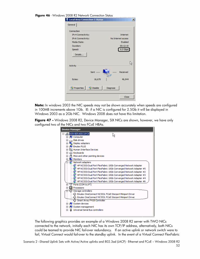
Scenario 2 –Shared Uplink Sets with Active/Active uplinks and 802.3ad (LACP) - Ethernet and FCoE – Windows 2008 R2 52
Figure 46 - Windows 2008 R2 Network Connection Status
Note: In windows 2003 the NIC speeds may not be shown accurately when speeds are configured in 100MB increments above 1Gb. IE: if a NIC is configured for 2.5Gb it will be displayed in Windows 2003 as a 2Gb NIC. Windows 2008 does not have this limitation.
Figure 47 - Windows 2008 R2, Device Manager, SIX NICs are shown, however, we have only configured two of the NICs and two FCoE HBAs.
The following graphics provides an example of a Windows 2008 R2 server with TWO NICs connected to the network, initially each NIC has its own TCP/IP address, alternatively, both NICs could be teamed to provide NIC fail-over redundancy. If an active uplink or network switch were to fail, Virtual Connect would fail-over to the standby uplink. In the event of a Virtual Connect FlexFabric
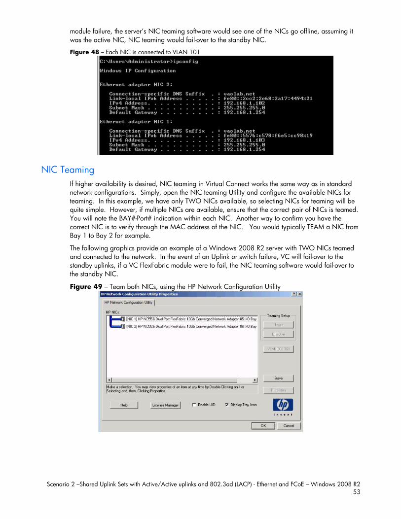
Scenario 2 –Shared Uplink Sets with Active/Active uplinks and 802.3ad (LACP) - Ethernet and FCoE – Windows 2008 R2 53
module failure, the server’s NIC teaming software would see one of the NICs go offline, assuming it was the active NIC, NIC teaming would fail-over to the standby NIC.
Figure 48 – Each NIC is connected to VLAN 101
NIC Teaming If higher availability is desired, NIC teaming in Virtual Connect works the same way as in standard network configurations. Simply, open the NIC teaming Utility and configure the available NICs for teaming. In this example, we have only TWO NICs available, so selecting NICs for teaming will be quite simple. However, if multiple NICs are available, ensure that the correct pair of NICs is teamed. You will note the BAY#-Port# indication within each NIC. Another way to confirm you have the correct NIC is to verify through the MAC address of the NIC. You would typically TEAM a NIC from Bay 1 to Bay 2 for example.
The following graphics provide an example of a Windows 2008 R2 server with TWO NICs teamed and connected to the network. In the event of an Uplink or switch failure, VC will fail-over to the standby uplinks, if a VC FlexFabric module were to fail, the NIC teaming software would fail-over to the standby NIC.
Figure 49 – Team both NICs, using the HP Network Configuration Utility
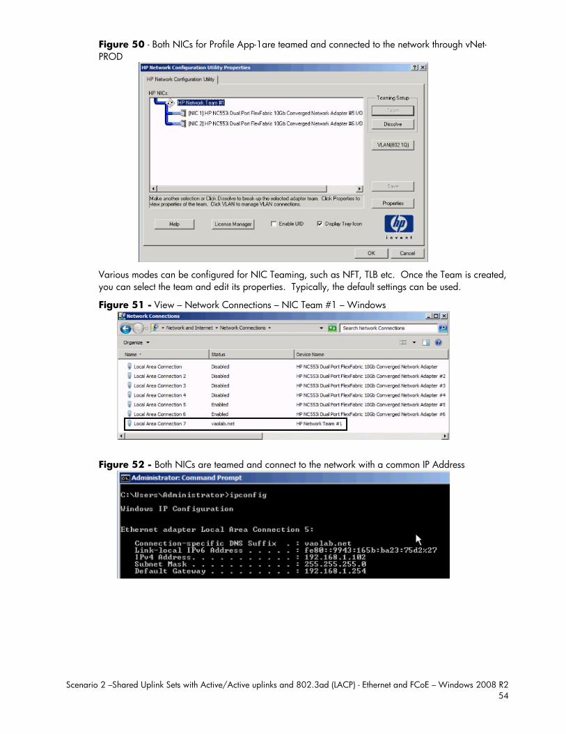
Scenario 2 –Shared Uplink Sets with Active/Active uplinks and 802.3ad (LACP) - Ethernet and FCoE – Windows 2008 R2 54
Figure 50 - Both NICs for Profile App-1are teamed and connected to the network through vNet-PROD
Various modes can be configured for NIC Teaming, such as NFT, TLB etc. Once the Team is created, you can select the team and edit its properties. Typically, the default settings can be used.
Figure 51 - View – Network Connections – NIC Team #1 – Windows
Figure 52 - Both NICs are teamed and connect to the network with a common IP Address
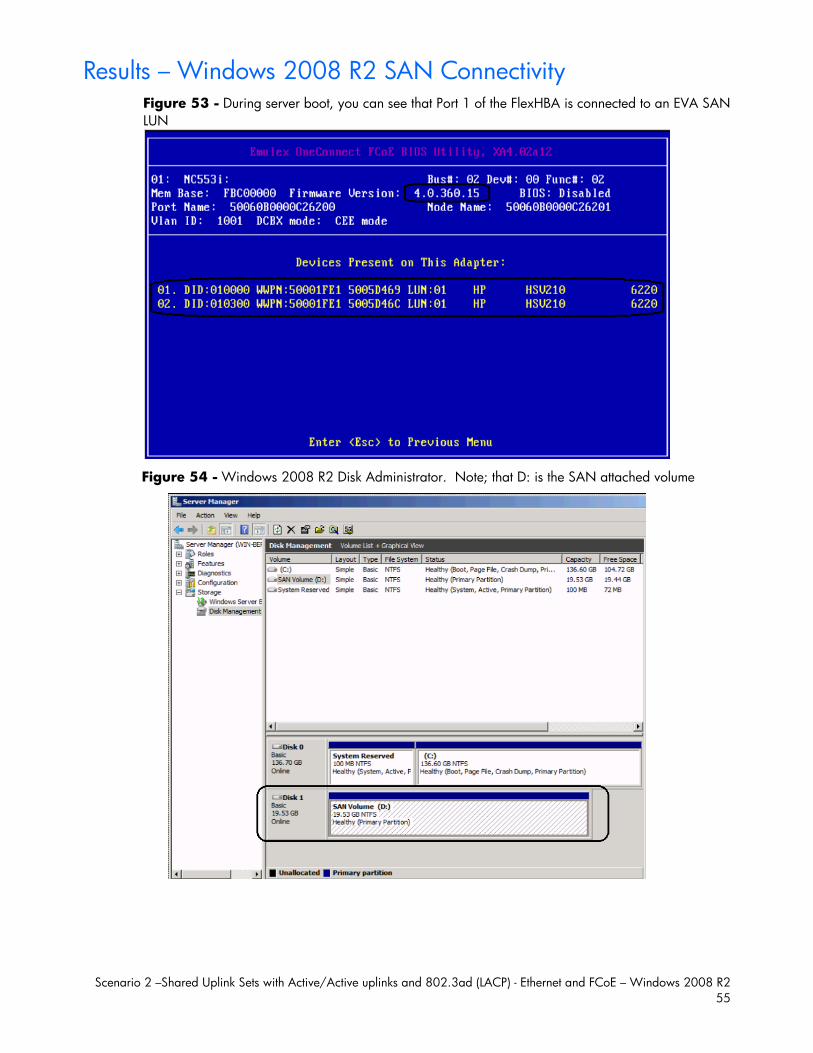
Scenario 2 –Shared Uplink Sets with Active/Active uplinks and 802.3ad (LACP) - Ethernet and FCoE – Windows 2008 R2 55
Results – Windows 2008 R2 SAN Connectivity Figure 53 - During server boot, you can see that Port 1 of the FlexHBA is connected to an EVA SAN LUN
Figure 54 - Windows 2008 R2 Disk Administrator. Note; that D: is the SAN attached volume
Scenario 2 –Shared Uplink Sets with Active/Active uplinks and 802.3ad (LACP) - Ethernet and FCoE – Windows 2008 R2 56
Summary We presented a Virtual Connect Network scenario by creating two shared uplink sets (SUS), each SUS is connected with TWO active uplinks, both SUS’ can actively pass traffic. We included a dual path SAN fabric for storage connectivity.
When VC profile App-1 is applied to the server in bay1 and is powered up, it has one NIC connected through FlexFabric module 1 (connected to VLAN-101-1), the second NIC is connected through FlexFabric module 2 (connected to VLAN-101-2). Each NIC is configured at 6Gb. These NICs could now be configured as individual NICs with their own IP address or as a pair of TEAMED NICs. Either NIC could be active. As a result, this server could access the network through either NIC or either uplink, depending on which NIC is active at the time. Each NIC is configured for 6Gb of network bandwidth and each FCoE port is configured for 4Gb of SAN bandwidth.
Additional NICs could be added within FlexFabric, by simply powering the server off and adding up to a total of 6 NICs, the NIC speed can then be adjusted accordingly to suit the needs of each NIC. If additional or less SAN bandwidth is required, the speed of the SAN connection can also be adjusted.
As additional servers are added to the enclosure, simply create additional profiles, or copy existing profiles, configure the NICs for LAN and SAN fabrics as required and apply them to the appropriate server bays and power the server on.
Scenario 3 – Shared Uplink Set with Active/Active Uplinks and 802.3ad (LACP) - Ethernet and FCoE Boot from SAN – Windows 2008 R2 57
Scenario 3 – Shared Uplink Set with Active/Active Uplinks and 802.3ad (LACP) - Ethernet and FCoE Boot from SAN – Windows 2008 R2
Overview This scenario will implement the Shared Uplink Set (SUS) to provide support for multiple VLANs. In this scenario, the upstream network switches connect a shared uplink set to two ports on each FlexFabric modules, LACP will be used to aggregate those links. This scenario is identical to Scenario 2, however, scenario 3 also provides the steps to configure a windows 2008 R2 server to Boot from SAN using the FCoE connections provided by FlexFabric. When using Virtual Connect/FlexFabric in a Boot from SAN implementation, no custom or special HBA configuration is required. The HBA configuration is controlled by Virtual Connect and maintained as part of the server profile. Once the server profile has been configured and applied to the server bays, the controller will be configured on the next and subsequent boot. When we later configure the server profile, we will also configure the HBA boot parameters.
As multiple VLANs will be supported in this configuration, the upstream switch ports connecting to the FlexFabric modules will be configured to properly present those VLANs. In this scenario, the upstream switch ports will be configured for VLAN trunking/VLAN tagging.
When configuring Virtual Connect, we can provide several ways to implement network fail-over or redundancy. One option would be to connect TWO uplinks to a single virtual connect network; those two uplinks would connect from different Virtual Connect modules within the enclosure and could then connect to the same upstream switch or two different upstream switches, depending on your redundancy needs. An alternative would be to configure TWO separate Virtual Connect networks, each with a single, or multiple, uplinks configured. Each option has its advantages and disadvantages. For example; an Active/Standby configuration places the redundancy at the VC level, where Active/Active places it at the OS NIC teaming or bonding level. We will review the first option in this scenario. We will review the second option in this scenario.
In addition, several Virtual Connect Networks can be configured to support the required networks to the servers within the BladeSystem enclosure. These networks could be used to separate the various network traffic types, such as iSCSI, backup and VMotion from production network traffic.
This scenario will also leverage the Fibre Channel over Ethernet (FCoE) capabilities of the FlexFabric modules. Each Fibre channel fabric will have two uplinks connected to each of the FlexFabric modules.
Requirements This scenario will support both Ethernet and fibre channel connectivity. In order to implement this scenario, an HP BladeSystem c7000 enclosure with one or more server blades and TWO Virtual Connect FlexFabric modules, installed in I/O Bays 1& 2 are required. In addition, we will require

Scenario
ONswitConportwill
Figand1 aupli
3 – Shared Up
E or TWO extch and is trannnect. The Fibts will need to be connected
ure 55 - Phyd 2 on the firstnd 2 on the sinks per fabric
plink Set with A
xternal Netwonsparent to thebre Channel uo be configured to the existin
ysical View; St network switecond networc, from ports X
Active/Active Up
ork switches. Ae network, anuplinks will coed to support Nng SAN fabric
hows two Ethtch and two Erk switch. TheX1 and X2 on
plinks and 802
As Virtual Cony standard mnnect to the eNPIV logins. cs.
ernet uplinks Ethernet uplinke SAN fabricsn module 1 to
2.3ad (LACP) - E
nnect does nomanaged switcexisting FC SA Two uplinks f
from Ports X5ks from Ports Xs are also con Fabric A and
Ethernet and FCWi
ot appear to tch will work wAN fabrics. Tfrom each Fle
5 and X6 on MX5 and X6 onnnected redund ports X1 and
CoE Boot from ndows 2008 R
the network aswith Virtual The SAN switcexFabric modu
Module 1 to Pn Module 2 tondantly, with Td X2 to Fabric
SAN – R2 58
s a
ch ule
orts 1 o Ports TWO c B.

Scenario 3 – Shared Uplink Set with Active/Active Uplinks and 802.3ad (LACP) - Ethernet and FCoE Boot from SAN – Windows 2008 R2 59
Figure 56 - Logical View; Logical View; the server blade profile is configured with TWO FlexNICs and 2 FlexHBAs. NICs 1 and 2 are connected to VLAN-101-x which are part of the Shared Uplink Sets, VLAN-Trunk-1 and VLAN-Trunk-2 respectively. The VLAN-Trunks are connected, at 10Gb, to a network switch, through Ports X5 and X6 on each FlexFabric Module in Bays 1 and 2. The FCoE SAN connections are connected through ports X1 and X2 on each FlexFabric module. In addition, SAN Fabric FCoE_A connects to the existing SAN Fabric A through port X1 on Module 1 (Bay 1) and FCoE_B connects to the existing SAN Fabric B through port X1 on Module 2 (Bay 2).
Switch configuration Appendices A and B provide a summary of the commands required to configure the switch in either a Cisco or a ProCurve network infrastructure. The configuration information provided in the appendices assumes the following information: The switch ports are configured as VLAN TRUNK ports (tagging) to support several VLANs. All
frames will be forwarding to Virtual Connect with VLAN tags. Optionally, one VLAN could be configured as (Default) untagged, if so, then a corresponding vNet within the Shared Uplink Set would be configured and set as “Default”.
Note: when adding additional uplinks to the SUS, if the additional uplinks are connecting from the same FlexFabric module to the same switch, in order to ensure all the uplinks are active, the switch ports will need to be configured for LACP within the same Link Aggregation Group. The network switch port should be configured for Spanning Tree Edge as Virtual Connect appears to the switch as an access device and not another switch. By configuring the port as Spanning Tree Edge, it allows the switch to place the port into a forwarding state much quicker than otherwise, this allows a newly connected port to come online and begin forwarding much quicker. The SAN connection will be made with redundant connections to each Fabric. SAN switch ports connecting to the FlexFabric module must be configured to accept NPIV logins.
VC CLI commands Many of the configuration settings within VC can also be accomplished via a CLI command set. In order to connect to VC via a CLI, open an SSH connection to the IP address of the active VCM. Once logged in, VC provides a CLI with help menus. Through this scenario the CLI commands to configure VC for each setting will also be provided.
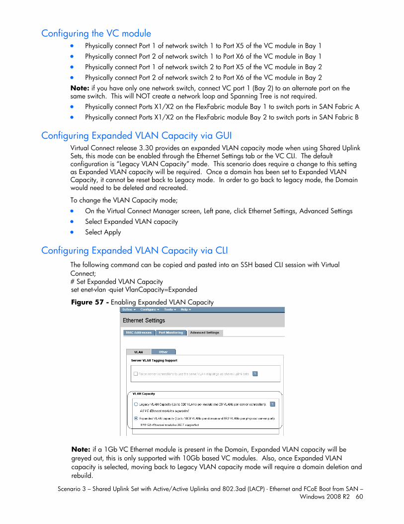
Scenario 3 – Shared Uplink Set with Active/Active Uplinks and 802.3ad (LACP) - Ethernet and FCoE Boot from SAN – Windows 2008 R2 60
Configuring the VC module Physically connect Port 1 of network switch 1 to Port X5 of the VC module in Bay 1 Physically connect Port 2 of network switch 1 to Port X6 of the VC module in Bay 1 Physically connect Port 1 of network switch 2 to Port X5 of the VC module in Bay 2 Physically connect Port 2 of network switch 2 to Port X6 of the VC module in Bay 2 Note: if you have only one network switch, connect VC port 1 (Bay 2) to an alternate port on the same switch. This will NOT create a network loop and Spanning Tree is not required. Physically connect Ports X1/X2 on the FlexFabric module Bay 1 to switch ports in SAN Fabric A Physically connect Ports X1/X2 on the FlexFabric module Bay 2 to switch ports in SAN Fabric B
Configuring Expanded VLAN Capacity via GUI Virtual Connect release 3.30 provides an expanded VLAN capacity mode when using Shared Uplink Sets, this mode can be enabled through the Ethernet Settings tab or the VC CLI. The default configuration is “Legacy VLAN Capacity” mode. This scenario does require a change to this setting as Expanded VLAN capacity will be required. Once a domain has been set to Expanded VLAN Capacity, it cannot be reset back to Legacy mode. In order to go back to legacy mode, the Domain would need to be deleted and recreated.
To change the VLAN Capacity mode; On the Virtual Connect Manager screen, Left pane, click Ethernet Settings, Advanced Settings Select Expanded VLAN capacity Select Apply
Configuring Expanded VLAN Capacity via CLI The following command can be copied and pasted into an SSH based CLI session with Virtual Connect; # Set Expanded VLAN Capacity set enet-vlan -quiet VlanCapacity=Expanded
Figure 57 - Enabling Expanded VLAN Capacity
Note: if a 1Gb VC Ethernet module is present in the Domain, Expanded VLAN capacity will be greyed out, this is only supported with 10Gb based VC modules. Also, once Expanded VLAN capacity is selected, moving back to Legacy VLAN capacity mode will require a domain deletion and rebuild.
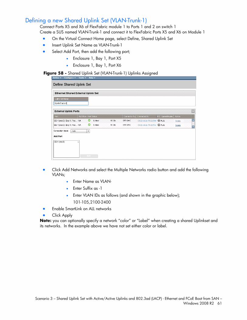
Scenario 3 – Shared Uplink Set with Active/Active Uplinks and 802.3ad (LACP) - Ethernet and FCoE Boot from SAN – Windows 2008 R2 61
Defining a new Shared Uplink Set (VLAN-Trunk-1) Connect Ports X5 and X6 of FlexFabric module 1 to Ports 1 and 2 on switch 1 Create a SUS named VLAN-Trunk-1 and connect it to FlexFabric Ports X5 and X6 on Module 1 On the Virtual Connect Home page, select Define, Shared Uplink Set Insert Uplink Set Name as VLAN-Trunk-1 Select Add Port, then add the following port;
Enclosure 1, Bay 1, Port X5
Enclosure 1, Bay 1, Port X6
Figure 58 - Shared Uplink Set (VLAN-Trunk-1) Uplinks Assigned
Click Add Networks and select the Multiple Networks radio button and add the following VLANs;
Enter Name as VLAN-
Enter Suffix as -1
Enter VLAN IDs as follows (and shown in the graphic below);
101-105,2100-2400 Enable SmartLink on ALL networks Click Apply
Note: you can optionally specify a network “color” or “Label” when creating a shared Uplinkset and its networks. In the example above we have not set either color or label.
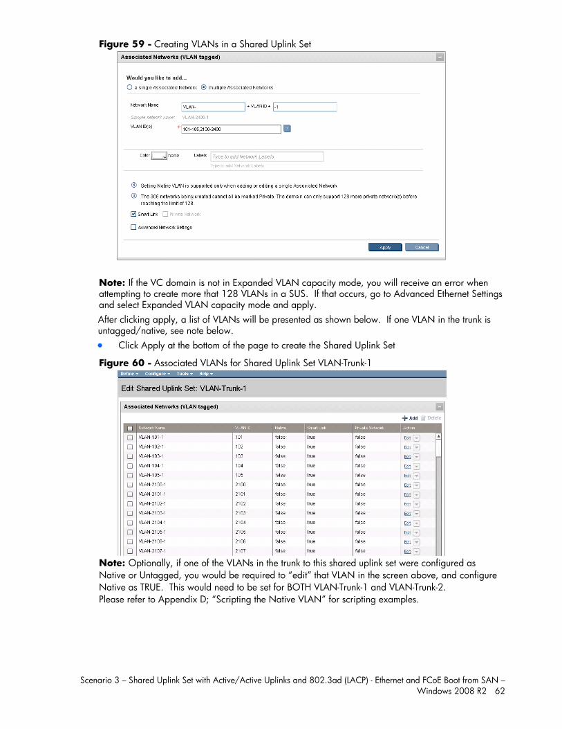
Scenario 3 – Shared Uplink Set with Active/Active Uplinks and 802.3ad (LACP) - Ethernet and FCoE Boot from SAN – Windows 2008 R2 62
Figure 59 - Creating VLANs in a Shared Uplink Set
Note: If the VC domain is not in Expanded VLAN capacity mode, you will receive an error when attempting to create more that 128 VLANs in a SUS. If that occurs, go to Advanced Ethernet Settings and select Expanded VLAN capacity mode and apply. After clicking apply, a list of VLANs will be presented as shown below. If one VLAN in the trunk is untagged/native, see note below. Click Apply at the bottom of the page to create the Shared Uplink Set
Figure 60 - Associated VLANs for Shared Uplink Set VLAN-Trunk-1
Note: Optionally, if one of the VLANs in the trunk to this shared uplink set were configured as Native or Untagged, you would be required to “edit” that VLAN in the screen above, and configure Native as TRUE. This would need to be set for BOTH VLAN-Trunk-1 and VLAN-Trunk-2. Please refer to Appendix D; “Scripting the Native VLAN” for scripting examples.
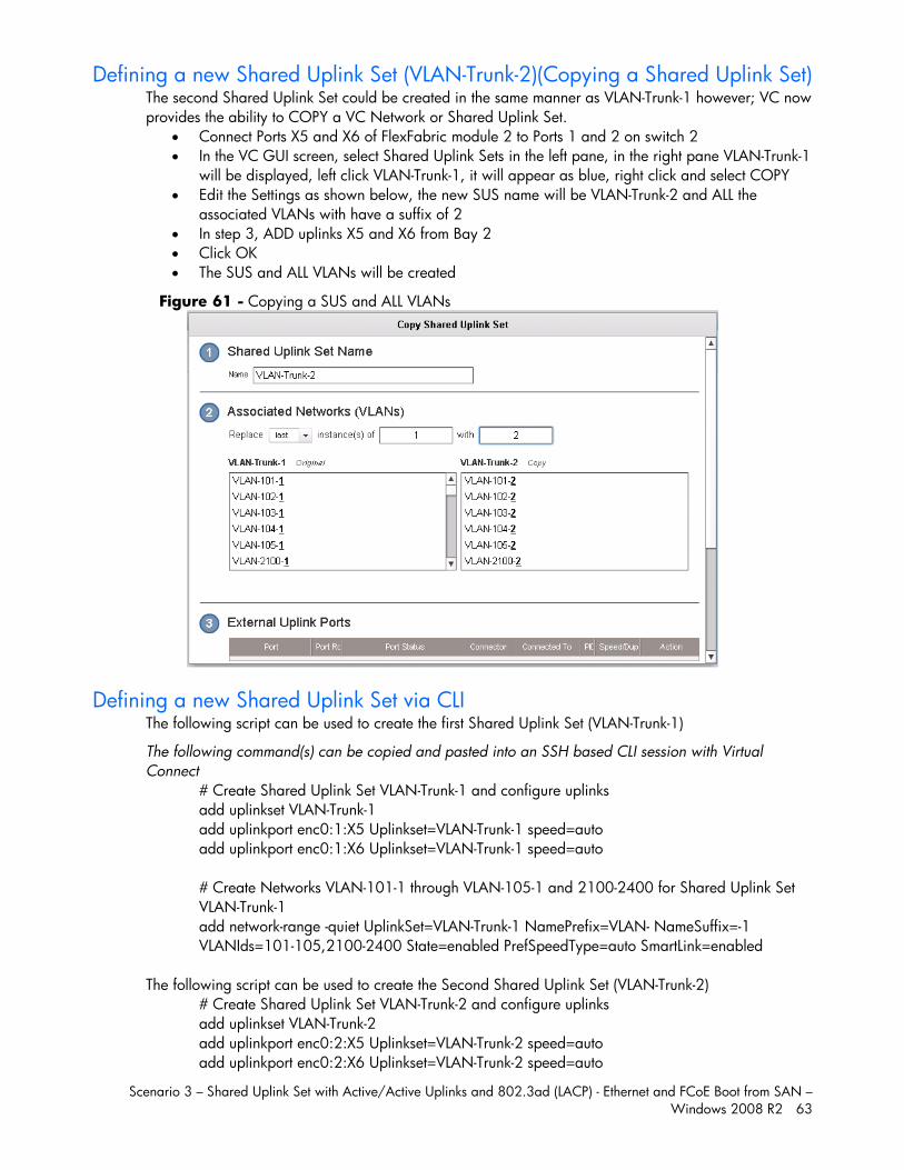
Scenario 3 – Shared Uplink Set with Active/Active Uplinks and 802.3ad (LACP) - Ethernet and FCoE Boot from SAN – Windows 2008 R2 63
Defining a new Shared Uplink Set (VLAN-Trunk-2)(Copying a Shared Uplink Set) The second Shared Uplink Set could be created in the same manner as VLAN-Trunk-1 however; VC now provides the ability to COPY a VC Network or Shared Uplink Set.
Connect Ports X5 and X6 of FlexFabric module 2 to Ports 1 and 2 on switch 2 In the VC GUI screen, select Shared Uplink Sets in the left pane, in the right pane VLAN-Trunk-1
will be displayed, left click VLAN-Trunk-1, it will appear as blue, right click and select COPY Edit the Settings as shown below, the new SUS name will be VLAN-Trunk-2 and ALL the
associated VLANs with have a suffix of 2 In step 3, ADD uplinks X5 and X6 from Bay 2 Click OK The SUS and ALL VLANs will be created
Figure 61 - Copying a SUS and ALL VLANs
Defining a new Shared Uplink Set via CLI The following script can be used to create the first Shared Uplink Set (VLAN-Trunk-1)
The following command(s) can be copied and pasted into an SSH based CLI session with Virtual Connect
# Create Shared Uplink Set VLAN-Trunk-1 and configure uplinks add uplinkset VLAN-Trunk-1 add uplinkport enc0:1:X5 Uplinkset=VLAN-Trunk-1 speed=auto add uplinkport enc0:1:X6 Uplinkset=VLAN-Trunk-1 speed=auto # Create Networks VLAN-101-1 through VLAN-105-1 and 2100-2400 for Shared Uplink Set VLAN-Trunk-1 add network-range -quiet UplinkSet=VLAN-Trunk-1 NamePrefix=VLAN- NameSuffix=-1 VLANIds=101-105,2100-2400 State=enabled PrefSpeedType=auto SmartLink=enabled
The following script can be used to create the Second Shared Uplink Set (VLAN-Trunk-2) # Create Shared Uplink Set VLAN-Trunk-2 and configure uplinks add uplinkset VLAN-Trunk-2 add uplinkport enc0:2:X5 Uplinkset=VLAN-Trunk-2 speed=auto add uplinkport enc0:2:X6 Uplinkset=VLAN-Trunk-2 speed=auto
Scenario 3 – Shared Uplink Set with Active/Active Uplinks and 802.3ad (LACP) - Ethernet and FCoE Boot from SAN – Windows 2008 R2 64
# Create Networks VLAN101-2 through VLAN105-2 and VLAN-2100-2 through VLAN-2400-2 for Shared Uplink Set VLAN-Trunk-2 add network-range -quiet UplinkSet=VLAN-Trunk-2 NamePrefix=VLAN- NameSuffix=-2 VLANIds=101-105,2100-2400 State=enabled PrefSpeedType=auto SmartLink=enabled
Summary Note: In this scenario we have created two independent Share Uplink Sets (SUS), each originating from the opposite FlexFabric Modules, by doing so we provide the ability to create separate and redundant connections out of the Virtual Connect domain. When we create the server profiles, you will see how the NICs will connect to VLANs accessed through the opposite VC module, which provides the ability to create an Active / Active uplink scenario. Alternatively, we could have created a single SUS and assigned both sets of these uplink ports to the same SUS, however, this would have provided an Active/Standby uplink scenario, as shown in Scenario 5.
Defining a new (FCoE) SAN Fabric via GUI Create a Fabric and name it “FCoE_A” On the Virtual Connect Manager screen, click Define, SAN Fabric to create the first Fabric Enter the Network Name of “FCoE_A” Select Add Port, then add the following ports;
Enclosure 1, Bay 1, Port X1 Enclosure 1, Bay 1, Port X2
Select the Advanced Settings Select Automatic Login Re-Distribution
Select Apply
Create a second Fabric and name it “FCoE_B” On the Virtual Connect Manager screen, click Define, SAN Fabric to create the second Fabric Enter the Network Name of “FCoE_B” Select Add Port, then add the following ports;
Enclosure 1, Bay 2, Port X1 Enclosure 1, Bay 2, Port X2
Select the Advanced Settings Select Automatic Login Re-Distribution
Select Apply
Defining SAN Fabrics via CLI The following command(s) can be copied and pasted into an SSH based CLI session with Virtual Connect #Create the SAN Fabrics FCoE_A and FCoE_B and configure uplinks as discussed above Add fabric FCoE_A Bay=1 Ports=1,2 LinkDist=Auto Add fabric FCoE_B Bay=2 Ports=1,2 LinkDist=Auto
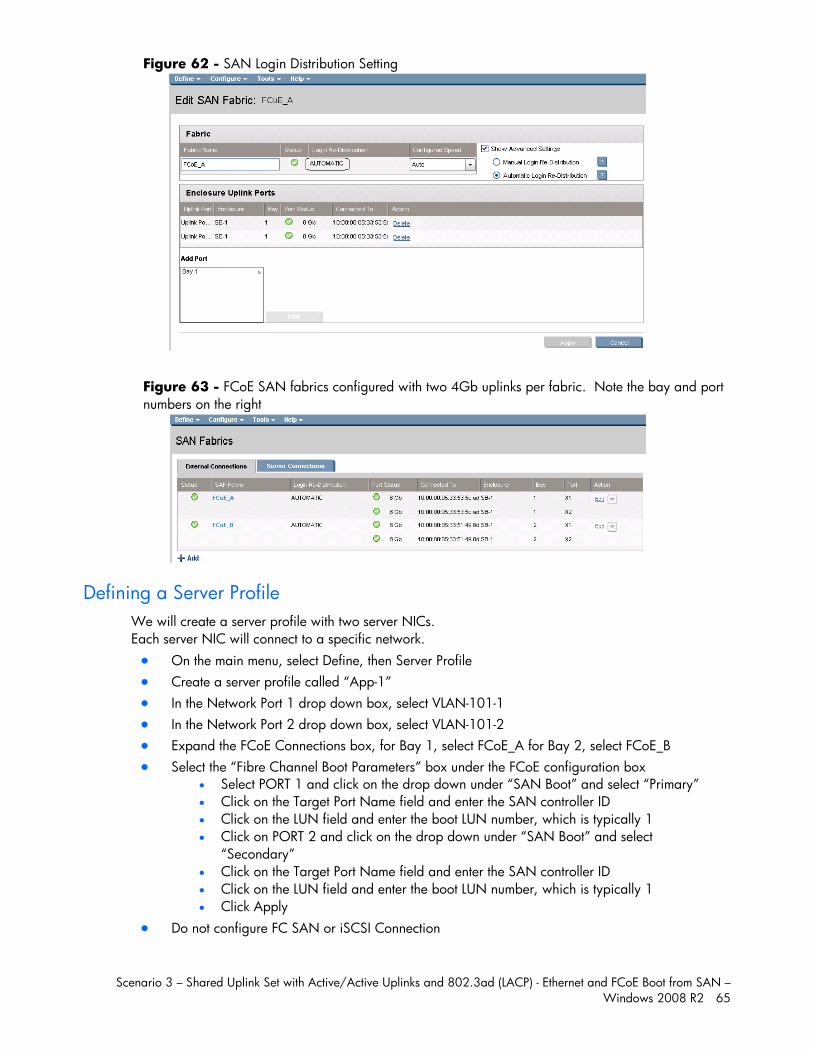
Scenario 3 – Shared Uplink Set with Active/Active Uplinks and 802.3ad (LACP) - Ethernet and FCoE Boot from SAN – Windows 2008 R2 65
Figure 62 - SAN Login Distribution Setting
Figure 63 - FCoE SAN fabrics configured with two 4Gb uplinks per fabric. Note the bay and port numbers on the right
Defining a Server Profile We will create a server profile with two server NICs. Each server NIC will connect to a specific network. On the main menu, select Define, then Server Profile Create a server profile called “App-1” In the Network Port 1 drop down box, select VLAN-101-1 In the Network Port 2 drop down box, select VLAN-101-2 Expand the FCoE Connections box, for Bay 1, select FCoE_A for Bay 2, select FCoE_B Select the “Fibre Channel Boot Parameters” box under the FCoE configuration box
Select PORT 1 and click on the drop down under “SAN Boot” and select “Primary” Click on the Target Port Name field and enter the SAN controller ID Click on the LUN field and enter the boot LUN number, which is typically 1 Click on PORT 2 and click on the drop down under “SAN Boot” and select
“Secondary” Click on the Target Port Name field and enter the SAN controller ID Click on the LUN field and enter the boot LUN number, which is typically 1 Click Apply
Do not configure FC SAN or iSCSI Connection
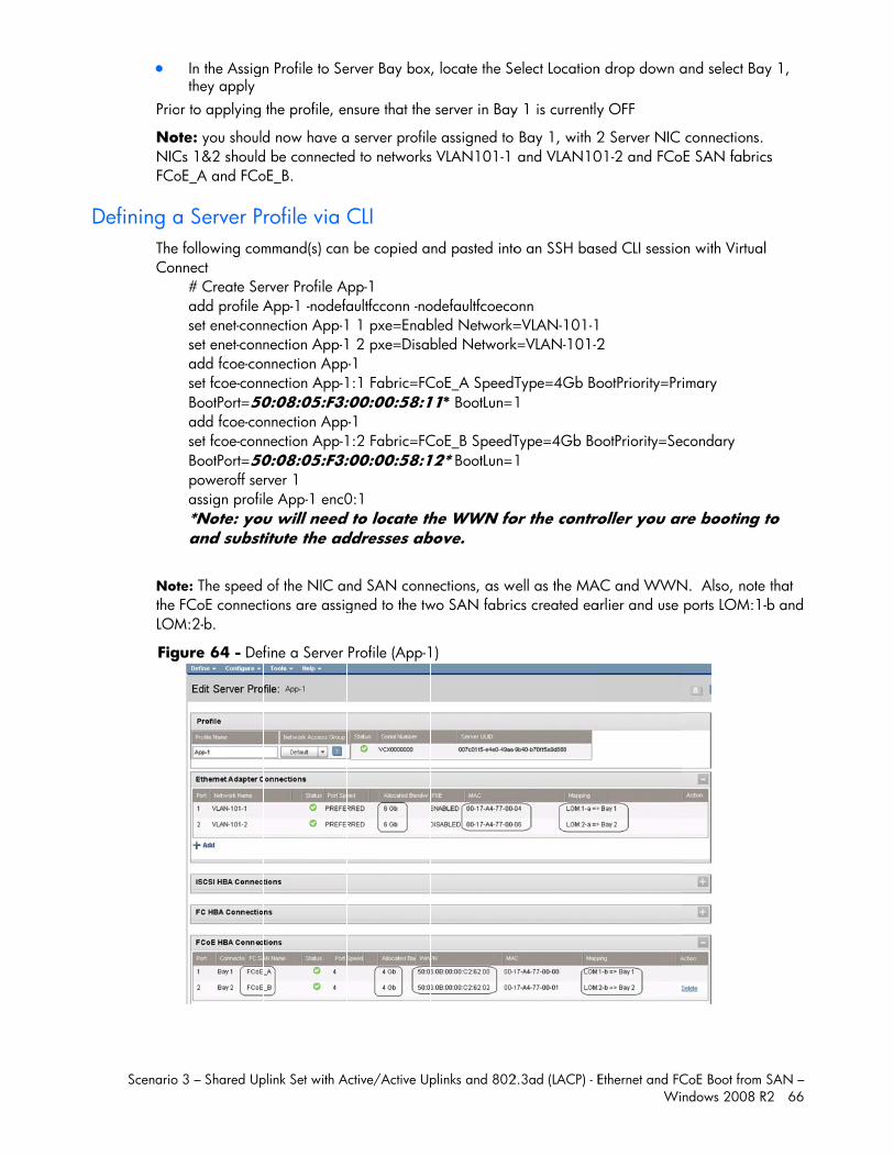
D
Scenario
Prio
NotNICFCo
Defining aThe Con
Notthe LOM
Fig
3 – Shared Up
In the Assignthey apply
r to applying
te: you shouldCs 1&2 shouldoE_A and FCo
a Server P following comnnect
# Create Seadd profile Aset enet-connset enet-connadd fcoe-coset fcoe-conBootPort=50add fcoe-coset fcoe-conBootPort=50poweroff seassign profi*Note: youand subst
te: The speed FCoE connect
M:2-b.
ure 64 - Def
plink Set with A
n Profile to Se
the profile, e
d now have ad be connecteoE_B.
rofile via mmand(s) can
erver Profile AApp-1 -nodefanection App-1nection App-1nnection Appnection App-10:08:05:F3:nnection Appnection App-10:08:05:F3:rver 1 le App-1 enc0
ou will need titute the ad
of the NIC ations are assig
fine a Server
Active/Active Up
erver Bay box
nsure that the
a server profiled to networks
CLI n be copied a
App-1 aultfcconn -no1 1 pxe=Enab1 2 pxe=Disabp-1 1:1 Fabric=FC:00:00:58:1p-1 1:2 Fabric=FC:00:00:58:1
0:1 d to locate thddresses ab
nd SAN conngned to the tw
Profile (App-1
plinks and 802
, locate the Se
server in Bay
e assigned to s VLAN101-1
nd pasted into
odefaultfcoecobled Network=bled Network
CoE_A SpeedT11* BootLun=
CoE_B SpeedT12* BootLun=
he WWN fobove.
nections, as wwo SAN fabric
1)
2.3ad (LACP) - E
elect Location
y 1 is currently
Bay 1, with 2 and VLAN10
o an SSH bas
onn =VLAN-101-1k=VLAN-101-2
Type=4Gb Bo1
Type=4Gb Bo1
or the contro
well as the MAcs created ea
Ethernet and FCWi
n drop down a
y OFF
2 Server NIC 01-2 and FCo
sed CLI sessio
2
ootPriority=Pr
ootPriority=Se
roller you ar
AC and WWNarlier and use
CoE Boot from ndows 2008 R
and select Bay
connections. oE SAN fabric
on with Virtual
imary
econdary
re booting t
N. Also, note ports LOM:1-
SAN – R2 66
y 1,
cs
l
to
that -b and
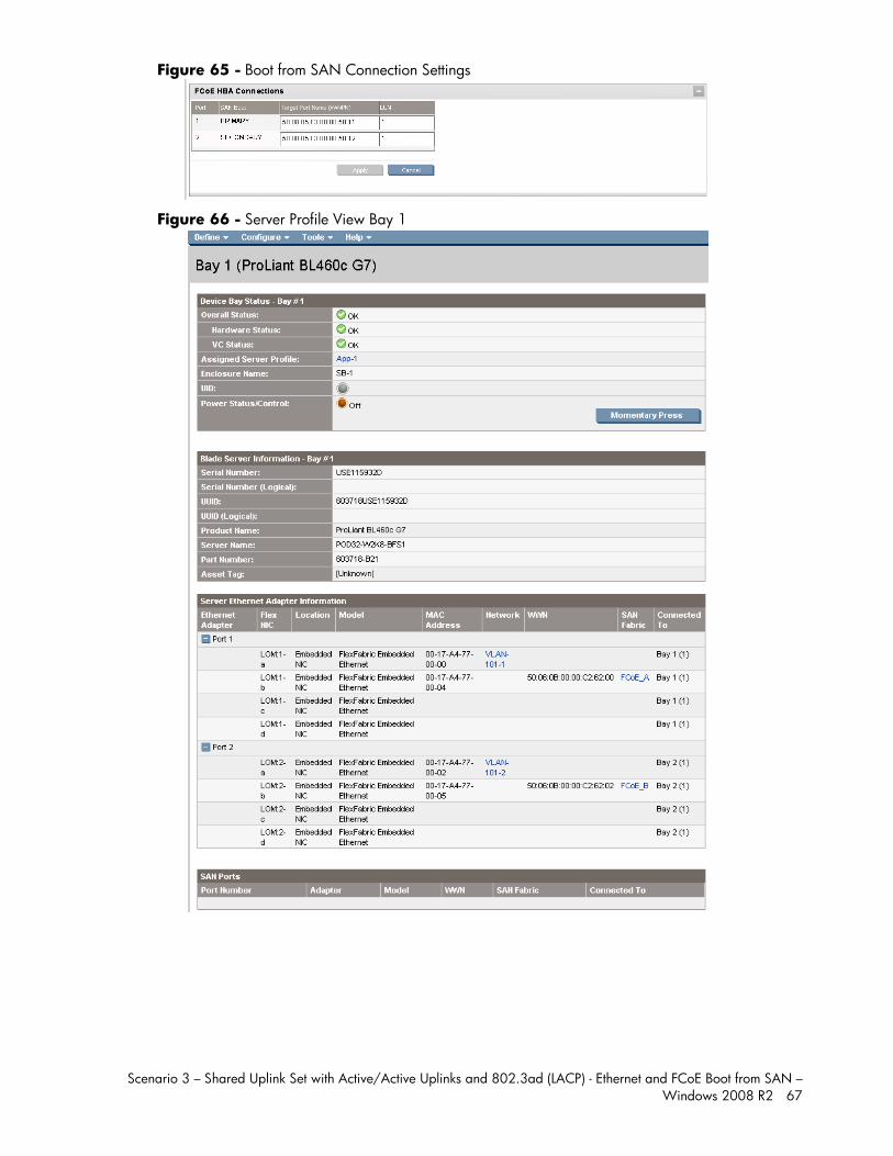
Scenario 3 – Shared Uplink Set with Active/Active Uplinks and 802.3ad (LACP) - Ethernet and FCoE Boot from SAN – Windows 2008 R2 67
Figure 65 - Boot from SAN Connection Settings
Figure 66 - Server Profile View Bay 1
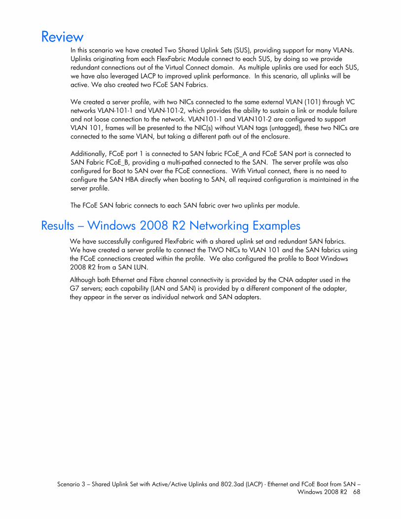
Scenario 3 – Shared Uplink Set with Active/Active Uplinks and 802.3ad (LACP) - Ethernet and FCoE Boot from SAN – Windows 2008 R2 68
Review In this scenario we have created Two Shared Uplink Sets (SUS), providing support for many VLANs. Uplinks originating from each FlexFabric Module connect to each SUS, by doing so we provide redundant connections out of the Virtual Connect domain. As multiple uplinks are used for each SUS, we have also leveraged LACP to improved uplink performance. In this scenario, all uplinks will be active. We also created two FCoE SAN Fabrics. We created a server profile, with two NICs connected to the same external VLAN (101) through VC networks VLAN-101-1 and VLAN-101-2, which provides the ability to sustain a link or module failure and not loose connection to the network. VLAN101-1 and VLAN101-2 are configured to support VLAN 101, frames will be presented to the NIC(s) without VLAN tags (untagged), these two NICs are connected to the same VLAN, but taking a different path out of the enclosure. Additionally, FCoE port 1 is connected to SAN fabric FCoE_A and FCoE SAN port is connected to SAN Fabric FCoE_B, providing a multi-pathed connected to the SAN. The server profile was also configured for Boot to SAN over the FCoE connections. With Virtual connect, there is no need to configure the SAN HBA directly when booting to SAN, all required configuration is maintained in the server profile. The FCoE SAN fabric connects to each SAN fabric over two uplinks per module.
Results – Windows 2008 R2 Networking Examples We have successfully configured FlexFabric with a shared uplink set and redundant SAN fabrics. We have created a server profile to connect the TWO NICs to VLAN 101 and the SAN fabrics using the FCoE connections created within the profile. We also configured the profile to Boot Windows 2008 R2 from a SAN LUN.
Although both Ethernet and Fibre channel connectivity is provided by the CNA adapter used in the G7 servers; each capability (LAN and SAN) is provided by a different component of the adapter, they appear in the server as individual network and SAN adapters.
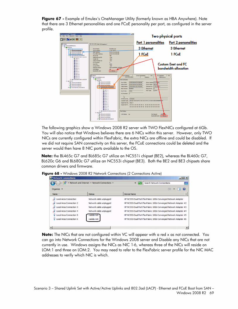
Scenario 3 – Shared Uplink Set with Active/Active Uplinks and 802.3ad (LACP) - Ethernet and FCoE Boot from SAN – Windows 2008 R2 69
Figure 67 - Example of Emulex's OneManager Utility (formerly known as HBA Anywhere). Note that there are 3 Ethernet personalities and one FCoE personality per port, as configured in the server profile.
The following graphics show a Windows 2008 R2 server with TWO FlexNICs configured at 6Gb. You will also notice that Windows believes there are 6 NICs within this server. However, only TWO NICs are currently configured within FlexFabric, the extra NICs are offline and could be disabled. If we did not require SAN connectivity on this server, the FCoE connections could be deleted and the server would then have 8 NIC ports available to the OS.
Note: the BL465c G7 and BL685c G7 utilize an NC551i chipset (BE2), whereas the BL460c G7, BL620c G6 and BL680c G7 utilize an NC553i chipset (BE3). Both the BE2 and BE3 chipsets share common drivers and firmware.
Figure 68 - Windows 2008 R2 Network Connections (2 Connections Active)
Note: The NICs that are not configured within VC will appear with a red x as not connected. You can go into Network Connections for the Windows 2008 server and Disable any NICs that are not currently in use. Windows assigns the NICs as NIC 1-6, whereas three of the NICs will reside on LOM:1 and three on LOM:2. You may need to refer to the FlexFabric server profile for the NIC MAC addresses to verify which NIC is which.
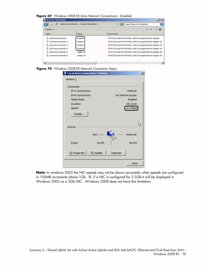
Scenario 3 – Shared Uplink Set with Active/Active Uplinks and 802.3ad (LACP) - Ethernet and FCoE Boot from SAN – Windows 2008 R2 70
Figure 69 - Windows 2008 R2 Extra Network Connections – Disabled
Figure 70 - Windows 2008 R2 Network Connection Status
Note: In windows 2003 the NIC speeds may not be shown accurately when speeds are configured in 100MB increments above 1Gb. IE: if a NIC is configured for 2.5Gb it will be displayed in Windows 2003 as a 2Gb NIC. Windows 2008 does not have this limitation.
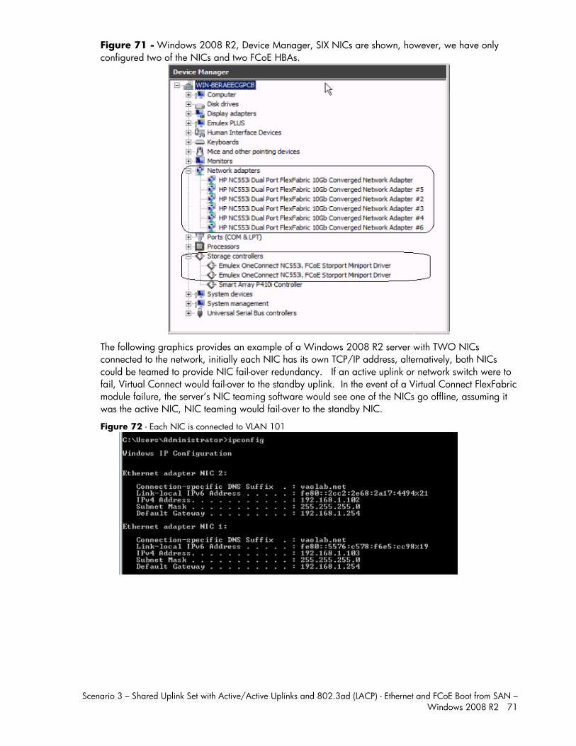
Scenario 3 – Shared Uplink Set with Active/Active Uplinks and 802.3ad (LACP) - Ethernet and FCoE Boot from SAN – Windows 2008 R2 71
Figure 71 - Windows 2008 R2, Device Manager, SIX NICs are shown, however, we have only configured two of the NICs and two FCoE HBAs.
The following graphics provides an example of a Windows 2008 R2 server with TWO NICs connected to the network, initially each NIC has its own TCP/IP address, alternatively, both NICs could be teamed to provide NIC fail-over redundancy. If an active uplink or network switch were to fail, Virtual Connect would fail-over to the standby uplink. In the event of a Virtual Connect FlexFabric module failure, the server’s NIC teaming software would see one of the NICs go offline, assuming it was the active NIC, NIC teaming would fail-over to the standby NIC.
Figure 72 - Each NIC is connected to VLAN 101
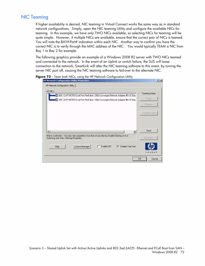
Scenario 3 – Shared Uplink Set with Active/Active Uplinks and 802.3ad (LACP) - Ethernet and FCoE Boot from SAN – Windows 2008 R2 72
NIC Teaming If higher availability is desired, NIC teaming in Virtual Connect works the same way as in standard network configurations. Simply, open the NIC teaming Utility and configure the available NICs for teaming. In this example, we have only TWO NICs available, so selecting NICs for teaming will be quite simple. However, if multiple NICs are available, ensure that the correct pair of NICs is teamed. You will note the BAY#-Port# indication within each NIC. Another way to confirm you have the correct NIC is to verify through the MAC address of the NIC. You would typically TEAM a NIC from Bay 1 to Bay 2 for example.
The following graphics provide an example of a Windows 2008 R2 server with TWO NICs teamed and connected to the network. In the event of an Uplink or switch failure, the SUS will loose connection to the network; SmartLink will alter the NIC teaming software to this event, by turning the server NIC port off, causing the NIC teaming software to fail-over to the alternate NIC.
Figure 73 – Team both NICs, using the HP Network Configuration Utility
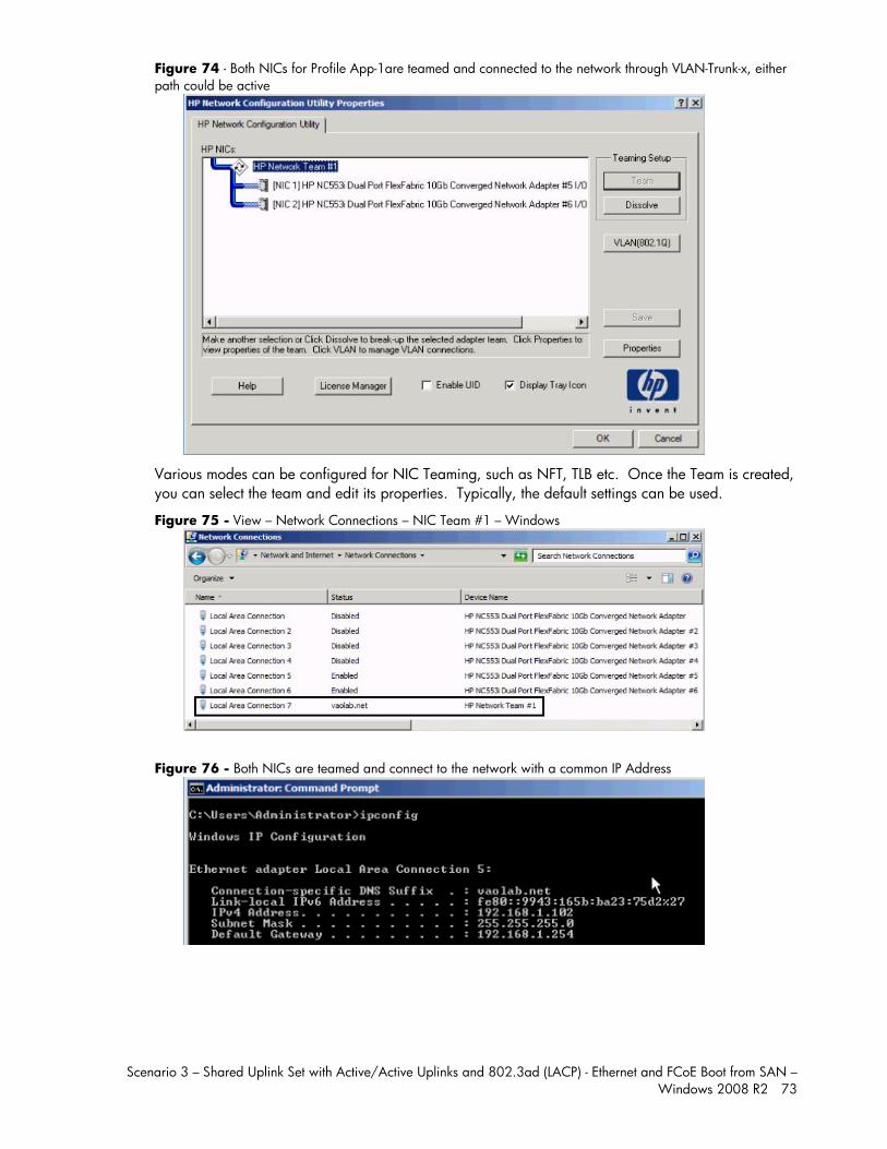
Scenario 3 – Shared Uplink Set with Active/Active Uplinks and 802.3ad (LACP) - Ethernet and FCoE Boot from SAN – Windows 2008 R2 73
Figure 74 - Both NICs for Profile App-1are teamed and connected to the network through VLAN-Trunk-x, either path could be active
Various modes can be configured for NIC Teaming, such as NFT, TLB etc. Once the Team is created, you can select the team and edit its properties. Typically, the default settings can be used.
Figure 75 - View – Network Connections – NIC Team #1 – Windows
Figure 76 - Both NICs are teamed and connect to the network with a common IP Address
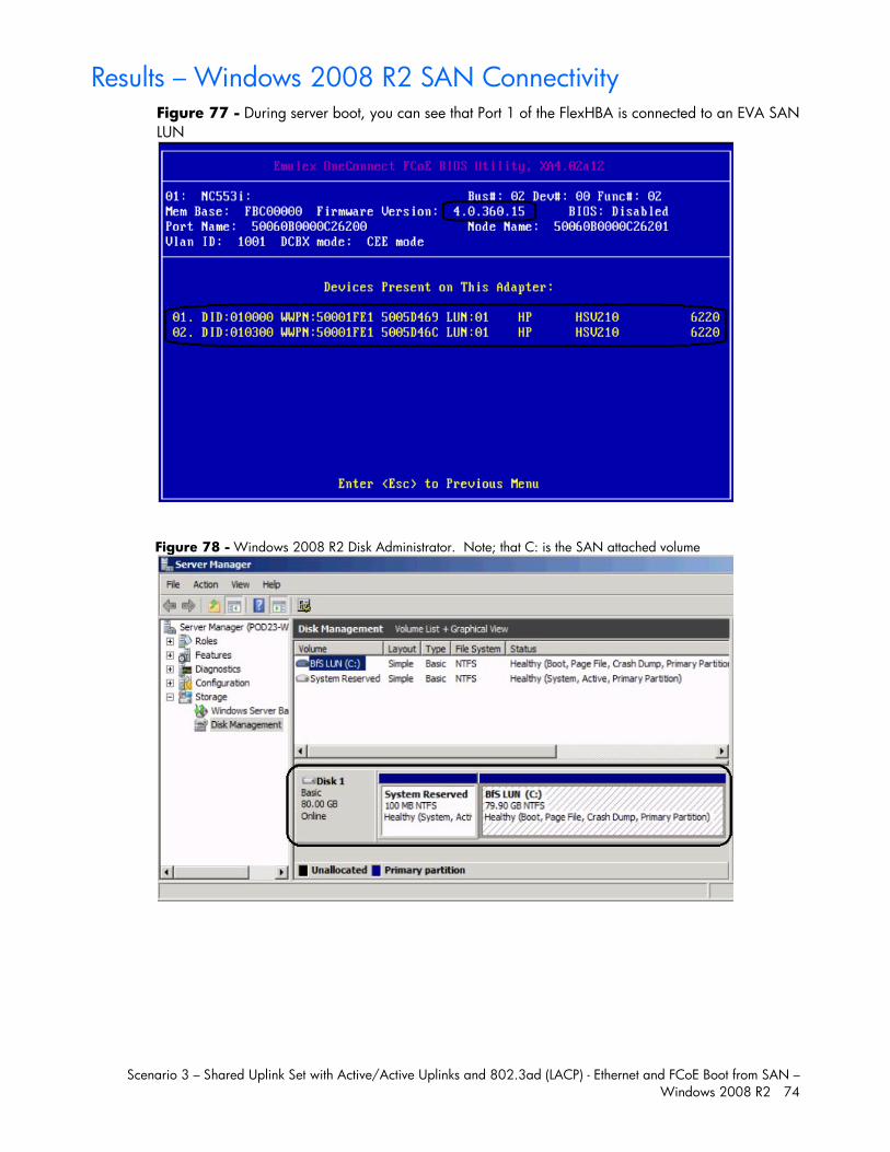
Scenario 3 – Shared Uplink Set with Active/Active Uplinks and 802.3ad (LACP) - Ethernet and FCoE Boot from SAN – Windows 2008 R2 74
Results – Windows 2008 R2 SAN Connectivity Figure 77 - During server boot, you can see that Port 1 of the FlexHBA is connected to an EVA SAN LUN
Figure 78 - Windows 2008 R2 Disk Administrator. Note; that C: is the SAN attached volume
Scenario 3 – Shared Uplink Set with Active/Active Uplinks and 802.3ad (LACP) - Ethernet and FCoE Boot from SAN – Windows 2008 R2 75
Summary We presented a Virtual Connect Network scenario by creating two shared uplink sets (SUS), each SUS is connected with TWO active uplinks, both SUS’ can actively pass traffic. We included a dual path FCoE SAN fabric for storage connectivity and boot to SAN.
When VC profile App-1 is applied to the server in bay1 and is powered up, it has one NIC connected through FlexFabric module 1 (connected to VLAN-101-1), the second NIC is connected through FlexFabric module 2 (connected to VLAN-101-2). Each NIC is configured at 6Gb. These NICs could now be configured as individual NICs with their own IP address or as a pair of TEAMED NICs. Either NIC could be active. As a result, this server could access the network through either NIC or either uplink, depending on which NIC is active at the time. Each NIC is configured for 6Gb of network bandwidth and each FCoE port is configured for 4Gb of SAN bandwidth.
Additional NICs could be added within FlexFabric, by simply powering the server off and adding up to a total of 6 NICs, the NIC speed can then be adjusted accordingly to suit the needs of each NIC. If additional or less SAN bandwidth is required, the speed of the SAN connection can also be adjusted.
As additional servers are added to the enclosure, simply create additional profiles, or copy existing profiles, configure the NICs for LAN and SAN fabrics as required and apply them to the appropriate server bays and power the server on.
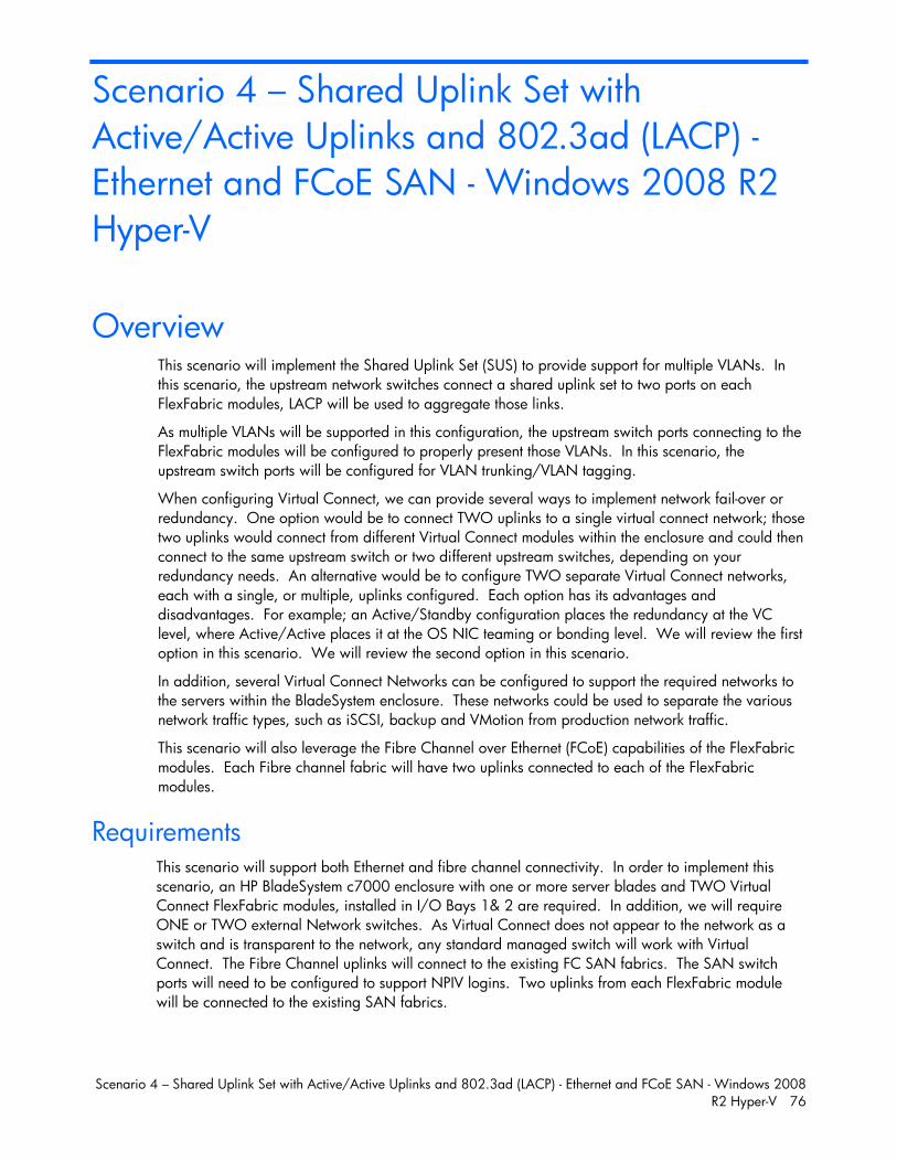
Scenario 4 – Shared Uplink Set with Active/Active Uplinks and 802.3ad (LACP) - Ethernet and FCoE SAN - Windows 2008 R2 Hyper-V 76
Scenario 4 – Shared Uplink Set with Active/Active Uplinks and 802.3ad (LACP) - Ethernet and FCoE SAN - Windows 2008 R2 Hyper-V
Overview This scenario will implement the Shared Uplink Set (SUS) to provide support for multiple VLANs. In this scenario, the upstream network switches connect a shared uplink set to two ports on each FlexFabric modules, LACP will be used to aggregate those links.
As multiple VLANs will be supported in this configuration, the upstream switch ports connecting to the FlexFabric modules will be configured to properly present those VLANs. In this scenario, the upstream switch ports will be configured for VLAN trunking/VLAN tagging.
When configuring Virtual Connect, we can provide several ways to implement network fail-over or redundancy. One option would be to connect TWO uplinks to a single virtual connect network; those two uplinks would connect from different Virtual Connect modules within the enclosure and could then connect to the same upstream switch or two different upstream switches, depending on your redundancy needs. An alternative would be to configure TWO separate Virtual Connect networks, each with a single, or multiple, uplinks configured. Each option has its advantages and disadvantages. For example; an Active/Standby configuration places the redundancy at the VC level, where Active/Active places it at the OS NIC teaming or bonding level. We will review the first option in this scenario. We will review the second option in this scenario.
In addition, several Virtual Connect Networks can be configured to support the required networks to the servers within the BladeSystem enclosure. These networks could be used to separate the various network traffic types, such as iSCSI, backup and VMotion from production network traffic.
This scenario will also leverage the Fibre Channel over Ethernet (FCoE) capabilities of the FlexFabric modules. Each Fibre channel fabric will have two uplinks connected to each of the FlexFabric modules.
Requirements This scenario will support both Ethernet and fibre channel connectivity. In order to implement this scenario, an HP BladeSystem c7000 enclosure with one or more server blades and TWO Virtual Connect FlexFabric modules, installed in I/O Bays 1& 2 are required. In addition, we will require ONE or TWO external Network switches. As Virtual Connect does not appear to the network as a switch and is transparent to the network, any standard managed switch will work with Virtual Connect. The Fibre Channel uplinks will connect to the existing FC SAN fabrics. The SAN switch ports will need to be configured to support NPIV logins. Two uplinks from each FlexFabric module will be connected to the existing SAN fabrics.
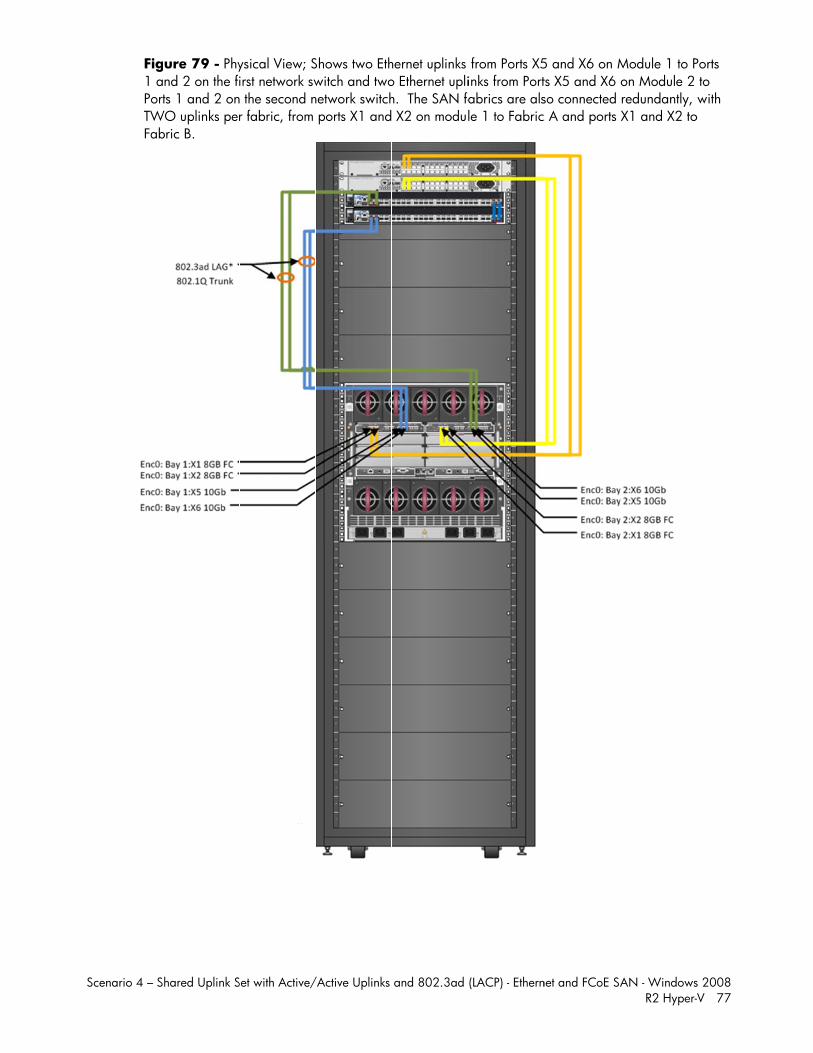
SScenario 4 – S
Fig1 aPortTWFab
hared Uplink S
ure 79 - Phynd 2 on the fits 1 and 2 on
WO uplinks perbric B.
Set with Active/
ysical View; Sirst network sw the second nr fabric, from
/Active Uplinks
Shows two Ethwitch and twonetwork switch ports X1 and
and 802.3ad
hernet uplinks o Ethernet uplih. The SAN fa X2 on modu
(LACP) - Ethern
from Ports X5inks from Portabrics are alsle 1 to Fabric
net and FCoE SA
5 and X6 on Mts X5 and X6 so connected c A and ports
AN - WindowsR2 Hyper-
Module 1 to Pon Module 2 redundantly, X1 and X2 to
s 2008 -V 77
Ports to with o
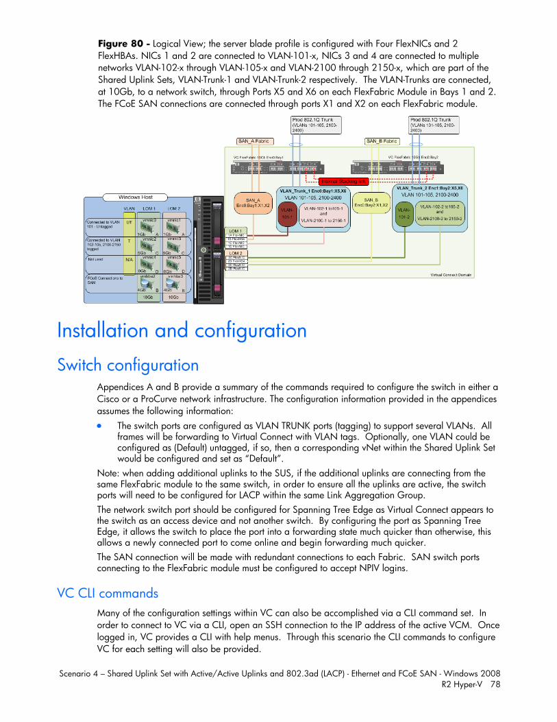
Scenario 4 – Shared Uplink Set with Active/Active Uplinks and 802.3ad (LACP) - Ethernet and FCoE SAN - Windows 2008 R2 Hyper-V 78
Figure 80 - Logical View; the server blade profile is configured with Four FlexNICs and 2 FlexHBAs. NICs 1 and 2 are connected to VLAN-101-x, NICs 3 and 4 are connected to multiple networks VLAN-102-x through VLAN-105-x and VLAN-2100 through 2150-x, which are part of the Shared Uplink Sets, VLAN-Trunk-1 and VLAN-Trunk-2 respectively. The VLAN-Trunks are connected, at 10Gb, to a network switch, through Ports X5 and X6 on each FlexFabric Module in Bays 1 and 2. The FCoE SAN connections are connected through ports X1 and X2 on each FlexFabric module.
Installation and configuration
Switch configuration Appendices A and B provide a summary of the commands required to configure the switch in either a Cisco or a ProCurve network infrastructure. The configuration information provided in the appendices assumes the following information: The switch ports are configured as VLAN TRUNK ports (tagging) to support several VLANs. All
frames will be forwarding to Virtual Connect with VLAN tags. Optionally, one VLAN could be configured as (Default) untagged, if so, then a corresponding vNet within the Shared Uplink Set would be configured and set as “Default”.
Note: when adding additional uplinks to the SUS, if the additional uplinks are connecting from the same FlexFabric module to the same switch, in order to ensure all the uplinks are active, the switch ports will need to be configured for LACP within the same Link Aggregation Group. The network switch port should be configured for Spanning Tree Edge as Virtual Connect appears to the switch as an access device and not another switch. By configuring the port as Spanning Tree Edge, it allows the switch to place the port into a forwarding state much quicker than otherwise, this allows a newly connected port to come online and begin forwarding much quicker. The SAN connection will be made with redundant connections to each Fabric. SAN switch ports connecting to the FlexFabric module must be configured to accept NPIV logins.
VC CLI commands Many of the configuration settings within VC can also be accomplished via a CLI command set. In order to connect to VC via a CLI, open an SSH connection to the IP address of the active VCM. Once logged in, VC provides a CLI with help menus. Through this scenario the CLI commands to configure VC for each setting will also be provided.
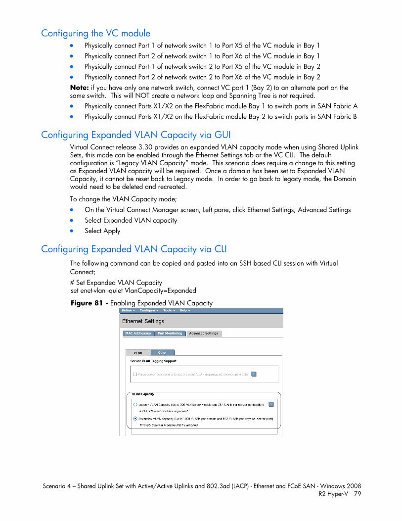
Scenario 4 – Shared Uplink Set with Active/Active Uplinks and 802.3ad (LACP) - Ethernet and FCoE SAN - Windows 2008 R2 Hyper-V 79
Configuring the VC module Physically connect Port 1 of network switch 1 to Port X5 of the VC module in Bay 1 Physically connect Port 2 of network switch 1 to Port X6 of the VC module in Bay 1 Physically connect Port 1 of network switch 2 to Port X5 of the VC module in Bay 2 Physically connect Port 2 of network switch 2 to Port X6 of the VC module in Bay 2 Note: if you have only one network switch, connect VC port 1 (Bay 2) to an alternate port on the same switch. This will NOT create a network loop and Spanning Tree is not required. Physically connect Ports X1/X2 on the FlexFabric module Bay 1 to switch ports in SAN Fabric A Physically connect Ports X1/X2 on the FlexFabric module Bay 2 to switch ports in SAN Fabric B
Configuring Expanded VLAN Capacity via GUI Virtual Connect release 3.30 provides an expanded VLAN capacity mode when using Shared Uplink Sets, this mode can be enabled through the Ethernet Settings tab or the VC CLI. The default configuration is “Legacy VLAN Capacity” mode. This scenario does require a change to this setting as Expanded VLAN capacity will be required. Once a domain has been set to Expanded VLAN Capacity, it cannot be reset back to Legacy mode. In order to go back to legacy mode, the Domain would need to be deleted and recreated.
To change the VLAN Capacity mode; On the Virtual Connect Manager screen, Left pane, click Ethernet Settings, Advanced Settings Select Expanded VLAN capacity Select Apply
Configuring Expanded VLAN Capacity via CLI The following command can be copied and pasted into an SSH based CLI session with Virtual Connect; # Set Expanded VLAN Capacity set enet-vlan -quiet VlanCapacity=Expanded
Figure 81 - Enabling Expanded VLAN Capacity
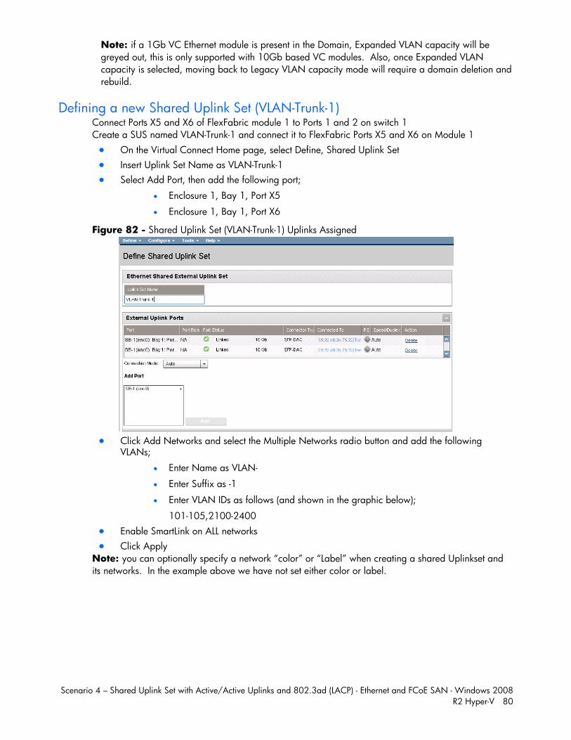
Scenario 4 – Shared Uplink Set with Active/Active Uplinks and 802.3ad (LACP) - Ethernet and FCoE SAN - Windows 2008 R2 Hyper-V 80
Note: if a 1Gb VC Ethernet module is present in the Domain, Expanded VLAN capacity will be greyed out, this is only supported with 10Gb based VC modules. Also, once Expanded VLAN capacity is selected, moving back to Legacy VLAN capacity mode will require a domain deletion and rebuild.
Defining a new Shared Uplink Set (VLAN-Trunk-1) Connect Ports X5 and X6 of FlexFabric module 1 to Ports 1 and 2 on switch 1 Create a SUS named VLAN-Trunk-1 and connect it to FlexFabric Ports X5 and X6 on Module 1 On the Virtual Connect Home page, select Define, Shared Uplink Set Insert Uplink Set Name as VLAN-Trunk-1 Select Add Port, then add the following port;
Enclosure 1, Bay 1, Port X5
Enclosure 1, Bay 1, Port X6
Figure 82 - Shared Uplink Set (VLAN-Trunk-1) Uplinks Assigned
Click Add Networks and select the Multiple Networks radio button and add the following
VLANs;
Enter Name as VLAN-
Enter Suffix as -1
Enter VLAN IDs as follows (and shown in the graphic below);
101-105,2100-2400 Enable SmartLink on ALL networks Click Apply
Note: you can optionally specify a network “color” or “Label” when creating a shared Uplinkset and its networks. In the example above we have not set either color or label.
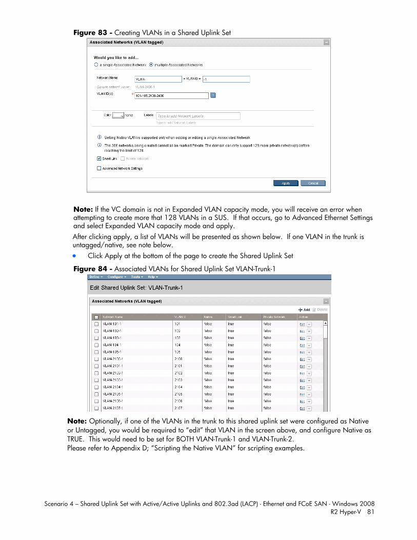
Scenario 4 – Shared Uplink Set with Active/Active Uplinks and 802.3ad (LACP) - Ethernet and FCoE SAN - Windows 2008 R2 Hyper-V 81
Figure 83 - Creating VLANs in a Shared Uplink Set
Note: If the VC domain is not in Expanded VLAN capacity mode, you will receive an error when attempting to create more that 128 VLANs in a SUS. If that occurs, go to Advanced Ethernet Settings and select Expanded VLAN capacity mode and apply. After clicking apply, a list of VLANs will be presented as shown below. If one VLAN in the trunk is untagged/native, see note below. Click Apply at the bottom of the page to create the Shared Uplink Set
Figure 84 - Associated VLANs for Shared Uplink Set VLAN-Trunk-1
Note: Optionally, if one of the VLANs in the trunk to this shared uplink set were configured as Native or Untagged, you would be required to “edit” that VLAN in the screen above, and configure Native as TRUE. This would need to be set for BOTH VLAN-Trunk-1 and VLAN-Trunk-2. Please refer to Appendix D; “Scripting the Native VLAN” for scripting examples.
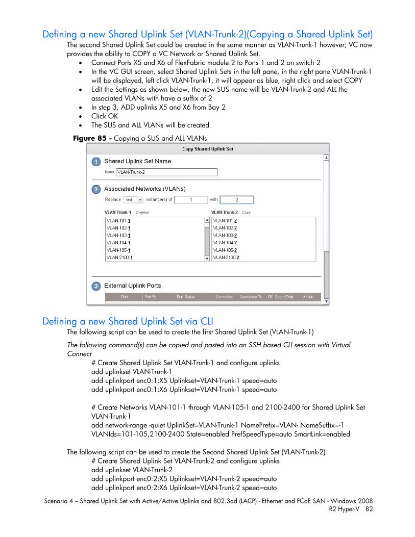
Scenario 4 – Shared Uplink Set with Active/Active Uplinks and 802.3ad (LACP) - Ethernet and FCoE SAN - Windows 2008 R2 Hyper-V 82
Defining a new Shared Uplink Set (VLAN-Trunk-2)(Copying a Shared Uplink Set) The second Shared Uplink Set could be created in the same manner as VLAN-Trunk-1 however; VC now provides the ability to COPY a VC Network or Shared Uplink Set.
Connect Ports X5 and X6 of FlexFabric module 2 to Ports 1 and 2 on switch 2 In the VC GUI screen, select Shared Uplink Sets in the left pane, in the right pane VLAN-Trunk-1
will be displayed, left click VLAN-Trunk-1, it will appear as blue, right click and select COPY Edit the Settings as shown below, the new SUS name will be VLAN-Trunk-2 and ALL the
associated VLANs with have a suffix of 2 In step 3, ADD uplinks X5 and X6 from Bay 2 Click OK The SUS and ALL VLANs will be created
Figure 85 - Copying a SUS and ALL VLANs
Defining a new Shared Uplink Set via CLI The following script can be used to create the first Shared Uplink Set (VLAN-Trunk-1)
The following command(s) can be copied and pasted into an SSH based CLI session with Virtual Connect
# Create Shared Uplink Set VLAN-Trunk-1 and configure uplinks add uplinkset VLAN-Trunk-1 add uplinkport enc0:1:X5 Uplinkset=VLAN-Trunk-1 speed=auto add uplinkport enc0:1:X6 Uplinkset=VLAN-Trunk-1 speed=auto # Create Networks VLAN-101-1 through VLAN-105-1 and 2100-2400 for Shared Uplink Set VLAN-Trunk-1 add network-range -quiet UplinkSet=VLAN-Trunk-1 NamePrefix=VLAN- NameSuffix=-1 VLANIds=101-105,2100-2400 State=enabled PrefSpeedType=auto SmartLink=enabled
The following script can be used to create the Second Shared Uplink Set (VLAN-Trunk-2) # Create Shared Uplink Set VLAN-Trunk-2 and configure uplinks add uplinkset VLAN-Trunk-2 add uplinkport enc0:2:X5 Uplinkset=VLAN-Trunk-2 speed=auto add uplinkport enc0:2:X6 Uplinkset=VLAN-Trunk-2 speed=auto
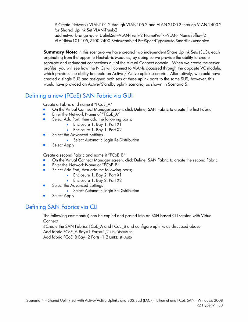
Scenario 4 – Shared Uplink Set with Active/Active Uplinks and 802.3ad (LACP) - Ethernet and FCoE SAN - Windows 2008 R2 Hyper-V 83
# Create Networks VLAN101-2 through VLAN105-2 and VLAN-2100-2 through VLAN-2400-2 for Shared Uplink Set VLAN-Trunk-2 add network-range -quiet UplinkSet=VLAN-Trunk-2 NamePrefix=VLAN- NameSuffix=-2 VLANIds=101-105,2100-2400 State=enabled PrefSpeedType=auto SmartLink=enabled
Summary Note: In this scenario we have created two independent Share Uplink Sets (SUS), each originating from the opposite FlexFabric Modules, by doing so we provide the ability to create separate and redundant connections out of the Virtual Connect domain. When we create the server profiles, you will see how the NICs will connect to VLANs accessed through the opposite VC module, which provides the ability to create an Active / Active uplink scenario. Alternatively, we could have created a single SUS and assigned both sets of these uplink ports to the same SUS, however, this would have provided an Active/Standby uplink scenario, as shown in Scenario 5.
Defining a new (FCoE) SAN Fabric via GUI Create a Fabric and name it “FCoE_A” On the Virtual Connect Manager screen, click Define, SAN Fabric to create the first Fabric Enter the Network Name of “FCoE_A” Select Add Port, then add the following ports;
Enclosure 1, Bay 1, Port X1 Enclosure 1, Bay 1, Port X2
Select the Advanced Settings Select Automatic Login Re-Distribution
Select Apply
Create a second Fabric and name it “FCoE_B” On the Virtual Connect Manager screen, click Define, SAN Fabric to create the second Fabric Enter the Network Name of “FCoE_B” Select Add Port, then add the following ports;
Enclosure 1, Bay 2, Port X1 Enclosure 1, Bay 2, Port X2
Select the Advanced Settings Select Automatic Login Re-Distribution
Select Apply
Defining SAN Fabrics via CLI The following command(s) can be copied and pasted into an SSH based CLI session with Virtual Connect #Create the SAN Fabrics FCoE_A and FCoE_B and configure uplinks as discussed above Add fabric FCoE_A Bay=1 Ports=1,2 LinkDist=Auto Add fabric FCoE_B Bay=2 Ports=1,2 LinkDist=Auto
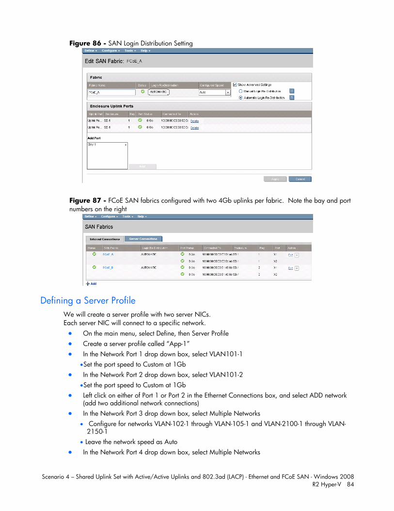
Scenario 4 – Shared Uplink Set with Active/Active Uplinks and 802.3ad (LACP) - Ethernet and FCoE SAN - Windows 2008 R2 Hyper-V 84
Figure 86 - SAN Login Distribution Setting
Figure 87 - FCoE SAN fabrics configured with two 4Gb uplinks per fabric. Note the bay and port numbers on the right
Defining a Server Profile We will create a server profile with two server NICs. Each server NIC will connect to a specific network. On the main menu, select Define, then Server Profile Create a server profile called “App-1” In the Network Port 1 drop down box, select VLAN101-1
Set the port speed to Custom at 1Gb In the Network Port 2 drop down box, select VLAN101-2
Set the port speed to Custom at 1Gb Left click on either of Port 1 or Port 2 in the Ethernet Connections box, and select ADD network
(add two additional network connections) In the Network Port 3 drop down box, select Multiple Networks
Configure for networks VLAN-102-1 through VLAN-105-1 and VLAN-2100-1 through VLAN-2150-1
Leave the network speed as Auto In the Network Port 4 drop down box, select Multiple Networks
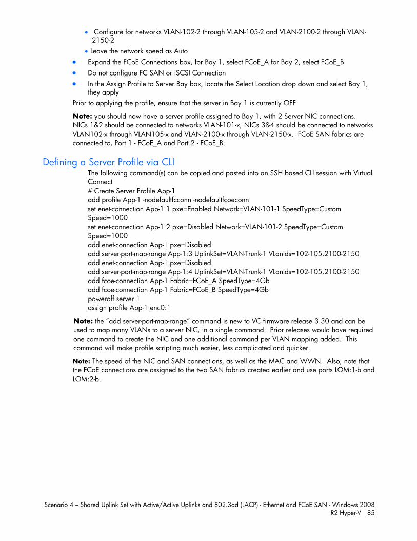
Scenario 4 – Shared Uplink Set with Active/Active Uplinks and 802.3ad (LACP) - Ethernet and FCoE SAN - Windows 2008 R2 Hyper-V 85
Configure for networks VLAN-102-2 through VLAN-105-2 and VLAN-2100-2 through VLAN-2150-2
Leave the network speed as Auto Expand the FCoE Connections box, for Bay 1, select FCoE_A for Bay 2, select FCoE_B Do not configure FC SAN or iSCSI Connection In the Assign Profile to Server Bay box, locate the Select Location drop down and select Bay 1,
they apply Prior to applying the profile, ensure that the server in Bay 1 is currently OFF
Note: you should now have a server profile assigned to Bay 1, with 2 Server NIC connections. NICs 1&2 should be connected to networks VLAN-101-x, NICs 3&4 should be connected to networks VLAN102-x through VLAN105-x and VLAN-2100-x through VLAN-2150-x. FCoE SAN fabrics are connected to, Port 1 - FCoE_A and Port 2 - FCoE_B.
Defining a Server Profile via CLI The following command(s) can be copied and pasted into an SSH based CLI session with Virtual Connect # Create Server Profile App-1 add profile App-1 -nodefaultfcconn -nodefaultfcoeconn set enet-connection App-1 1 pxe=Enabled Network=VLAN-101-1 SpeedType=Custom Speed=1000 set enet-connection App-1 2 pxe=Disabled Network=VLAN-101-2 SpeedType=Custom Speed=1000 add enet-connection App-1 pxe=Disabled add server-port-map-range App-1:3 UplinkSet=VLAN-Trunk-1 VLanIds=102-105,2100-2150 add enet-connection App-1 pxe=Disabled add server-port-map-range App-1:4 UplinkSet=VLAN-Trunk-1 VLanIds=102-105,2100-2150 add fcoe-connection App-1 Fabric=FCoE_A SpeedType=4Gb add fcoe-connection App-1 Fabric=FCoE_B SpeedType=4Gb poweroff server 1 assign profile App-1 enc0:1
Note: the “add server-port-map-range” command is new to VC firmware release 3.30 and can be used to map many VLANs to a server NIC, in a single command. Prior releases would have required one command to create the NIC and one additional command per VLAN mapping added. This command will make profile scripting much easier, less complicated and quicker. Note: The speed of the NIC and SAN connections, as well as the MAC and WWN. Also, note that the FCoE connections are assigned to the two SAN fabrics created earlier and use ports LOM:1-b and LOM:2-b.
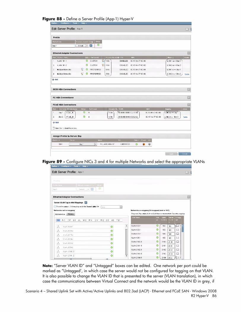
Scenario 4 – Shared Uplink Set with Active/Active Uplinks and 802.3ad (LACP) - Ethernet and FCoE SAN - Windows 2008 R2 Hyper-V 86
Figure 88 - Define a Server Profile (App-1) Hyper-V
Figure 89 - Configure NICs 3 and 4 for multiple Networks and select the appropriate VLANs
Note: “Server VLAN ID” and “Untagged” boxes can be edited. One network per port could be marked as “Untagged’, in which case the server would not be configured for tagging on that VLAN. It is also possible to change the VLAN ID that is presented to the server (VLAN translation), in which case the communications between Virtual Connect and the network would be the VLAN ID in grey, if
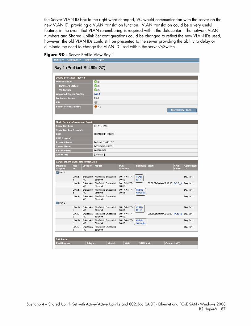
Scenario 4 – Shared Uplink Set with Active/Active Uplinks and 802.3ad (LACP) - Ethernet and FCoE SAN - Windows 2008 R2 Hyper-V 87
the Server VLAN ID box to the right were changed, VC would communication with the server on the new VLAN ID, providing a VLAN translation function. VLAN translation could be a very useful feature, in the event that VLAN renumbering is required within the datacenter. The network VLAN numbers and Shared Uplink Set configurations could be changed to reflect the new VLAN IDs used, however, the old VLAN IDs could still be presented to the server providing the ability to delay or eliminate the need to change the VLAN ID used within the server/vSwitch.
Figure 90 - Server Profile View Bay 1
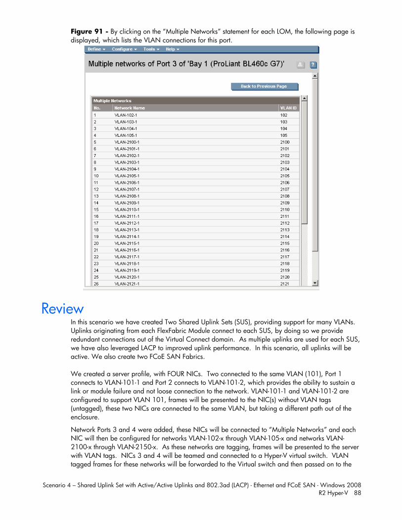
Scenario 4 – Shared Uplink Set with Active/Active Uplinks and 802.3ad (LACP) - Ethernet and FCoE SAN - Windows 2008 R2 Hyper-V 88
Figure 91 - By clicking on the “Multiple Networks” statement for each LOM, the following page is displayed, which lists the VLAN connections for this port.
Review In this scenario we have created Two Shared Uplink Sets (SUS), providing support for many VLANs. Uplinks originating from each FlexFabric Module connect to each SUS, by doing so we provide redundant connections out of the Virtual Connect domain. As multiple uplinks are used for each SUS, we have also leveraged LACP to improved uplink performance. In this scenario, all uplinks will be active. We also create two FCoE SAN Fabrics. We created a server profile, with FOUR NICs. Two connected to the same VLAN (101), Port 1 connects to VLAN-101-1 and Port 2 connects to VLAN-101-2, which provides the ability to sustain a link or module failure and not loose connection to the network. VLAN-101-1 and VLAN-101-2 are configured to support VLAN 101, frames will be presented to the NIC(s) without VLAN tags (untagged), these two NICs are connected to the same VLAN, but taking a different path out of the enclosure.
Network Ports 3 and 4 were added, these NICs will be connected to “Multiple Networks” and each NIC will then be configured for networks VLAN-102-x through VLAN-105-x and networks VLAN-2100-x through VLAN-2150-x. As these networks are tagging, frames will be presented to the server with VLAN tags. NICs 3 and 4 will be teamed and connected to a Hyper-V virtual switch. VLAN tagged frames for these networks will be forwarded to the Virtual switch and then passed on to the
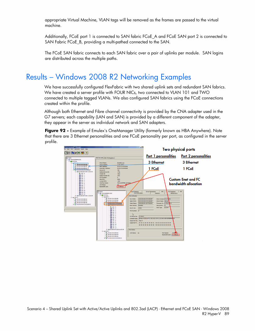
Scenario 4 – Shared Uplink Set with Active/Active Uplinks and 802.3ad (LACP) - Ethernet and FCoE SAN - Windows 2008 R2 Hyper-V 89
appropriate Virtual Machine, VLAN tags will be removed as the frames are passed to the virtual machine. Additionally, FCoE port 1 is connected to SAN fabric FCoE_A and FCoE SAN port 2 is connected to SAN Fabric FCoE_B, providing a multi-pathed connected to the SAN. The FCoE SAN fabric connects to each SAN fabric over a pair of uplinks per module. SAN logins are distributed across the multiple paths.
Results – Windows 2008 R2 Networking Examples We have successfully configured FlexFabric with two shared uplink sets and redundant SAN fabrics. We have created a server profile with FOUR NICs, two connected to VLAN 101 and TWO connected to multiple tagged VLANs. We also configured SAN fabrics using the FCoE connections created within the profile.
Although both Ethernet and Fibre channel connectivity is provided by the CNA adapter used in the G7 servers; each capability (LAN and SAN) is provided by a different component of the adapter, they appear in the server as individual network and SAN adapters.
Figure 92 - Example of Emulex's OneManager Utility (formerly known as HBA Anywhere). Note that there are 3 Ethernet personalities and one FCoE personality per port, as configured in the server profile.
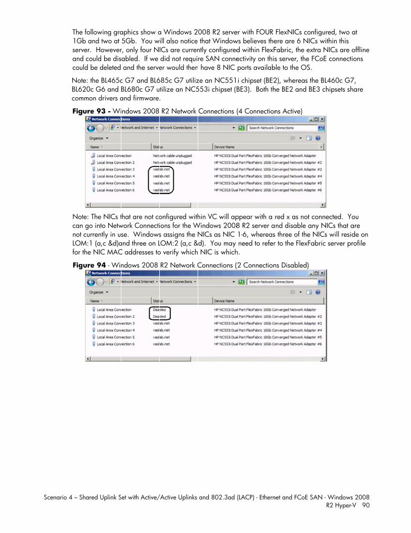
S
Scenario 4 – S
The 1Gbservandcou
NotBL6com
Fig
Notcannot LOMfor t
Fig
hared Uplink S
following grab and two at ver. Howeverd could be disld be deleted
e: the BL465c20c G6 and
mmon drivers a
ure 93 - Wi
te: The NICs t go into Netw currently in usM:1 (a,c &d)athe NIC MAC
ure 94 - Win
Set with Active/
aphics show a5Gb. You wr, only four Nabled. If we and the serve
c G7 and BL6BL680c G7 uand firmware.
indows 2008
that are not cowork Connectise. Windows
and three on LC addresses to
ndows 2008
/Active Uplinks
a Windows 2ill also notice ICs are curren did not requier would then
685c G7 utiliztilize an NC5.
R2 Network
onfigured withions for the Ws assigns the NLOM:2 (a,c &o verify which
R2 Network C
and 802.3ad
008 R2 serve that Windowntly configuredre SAN conne have 8 NIC
ze an NC551553i chipset (
Connections
hin VC will apWindows 2008
NICs as NIC &d). You may
NIC is which
Connections (
(LACP) - Ethern
er with FOUR ws believes thed within FlexFectivity on this ports availab
i chipset (BE2BE3). Both th
(4 Connection
ppear with a 8 R2 server a 1-6, whereas need to referh.
(2 Connection
net and FCoE SA
FlexNICs conere are 6 NICFabric, the exts server, the F
ble to the OS.
2), whereas thhe BE2 and BE
ns Active)
red x as not cnd disable an
s three of the Nr to the FlexFa
ns Disabled)
AN - WindowsR2 Hyper-
nfigured, two Cs within this tra NICs are oFCoE connecti
he BL460c G7E3 chipsets sh
connected. Yony NICs that aNICs will residabric server pr
s 2008 -V 90
at
offline ions
7, hare
ou are de on rofile
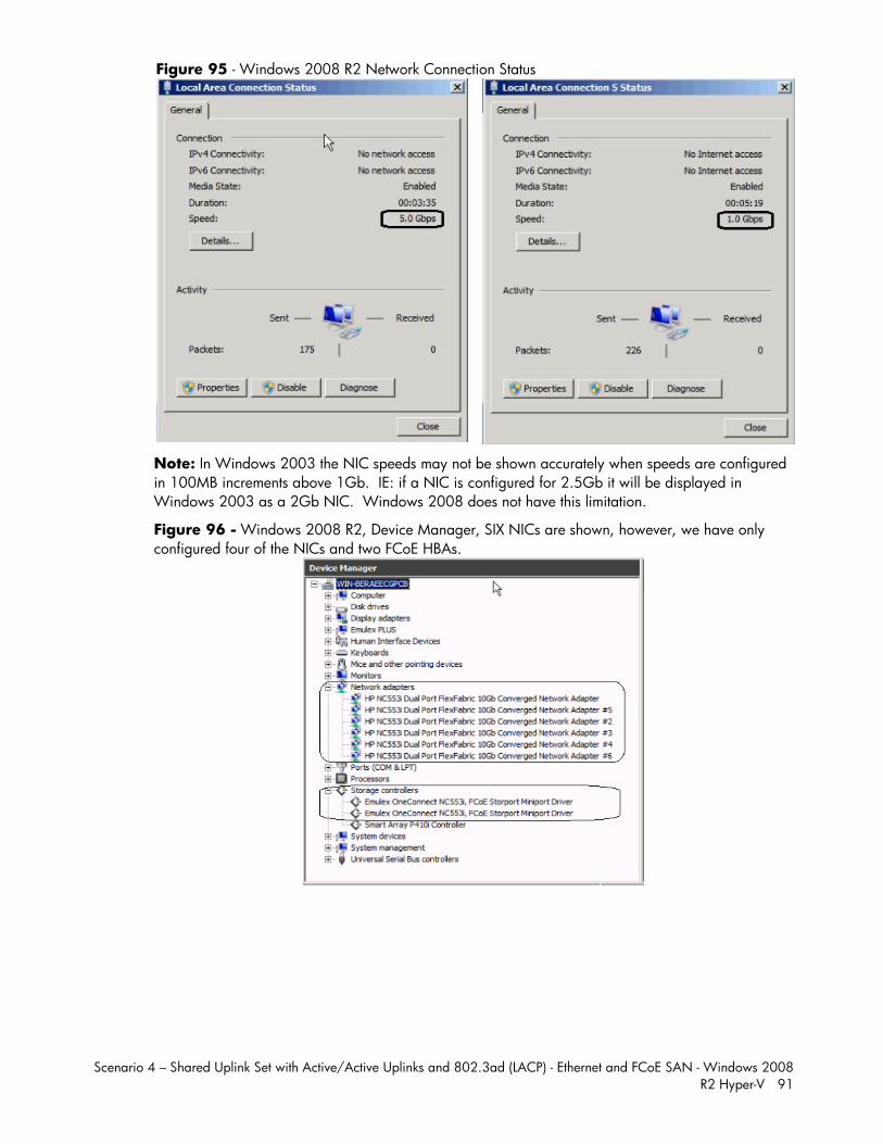
Scenario 4 – Shared Uplink Set with Active/Active Uplinks and 802.3ad (LACP) - Ethernet and FCoE SAN - Windows 2008 R2 Hyper-V 91
Figure 95 - Windows 2008 R2 Network Connection Status
Note: In Windows 2003 the NIC speeds may not be shown accurately when speeds are configured in 100MB increments above 1Gb. IE: if a NIC is configured for 2.5Gb it will be displayed in Windows 2003 as a 2Gb NIC. Windows 2008 does not have this limitation.
Figure 96 - Windows 2008 R2, Device Manager, SIX NICs are shown, however, we have only configured four of the NICs and two FCoE HBAs.
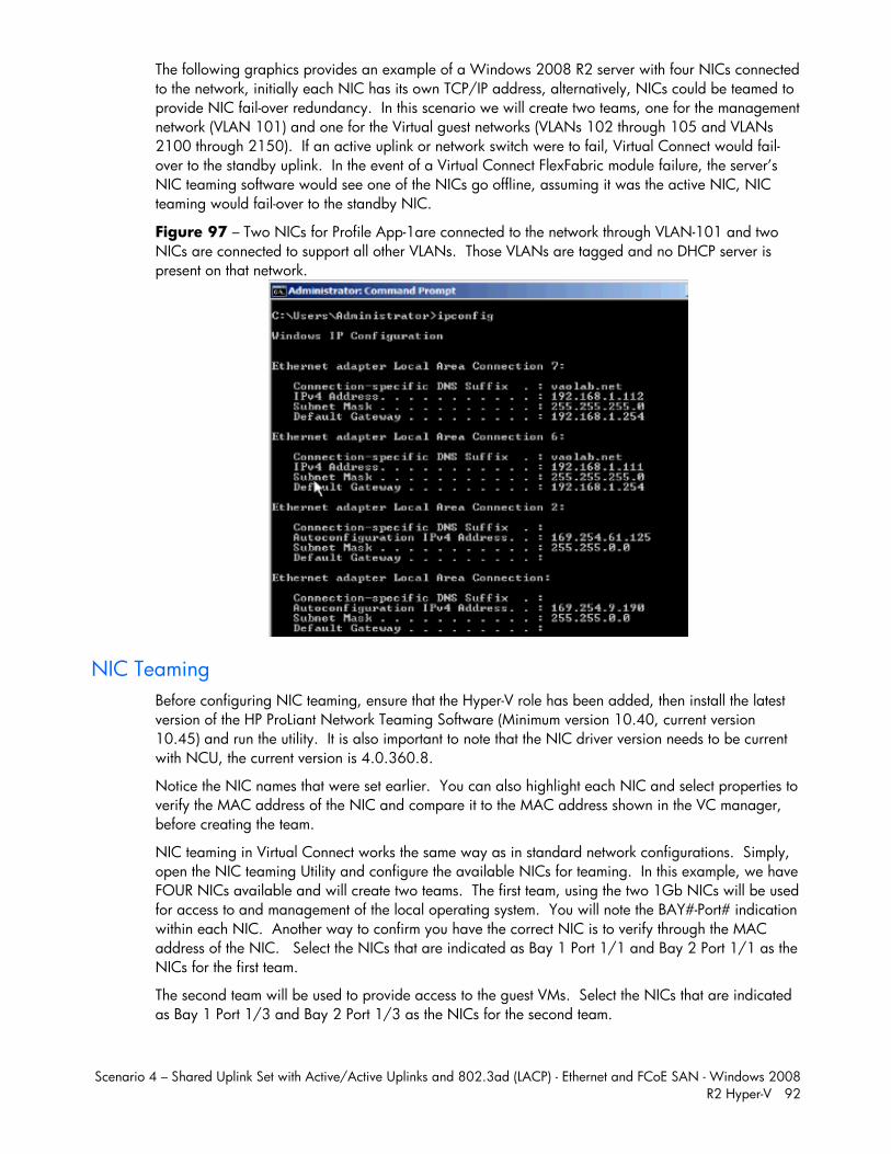
Scenario 4 – Shared Uplink Set with Active/Active Uplinks and 802.3ad (LACP) - Ethernet and FCoE SAN - Windows 2008 R2 Hyper-V 92
The following graphics provides an example of a Windows 2008 R2 server with four NICs connected to the network, initially each NIC has its own TCP/IP address, alternatively, NICs could be teamed to provide NIC fail-over redundancy. In this scenario we will create two teams, one for the management network (VLAN 101) and one for the Virtual guest networks (VLANs 102 through 105 and VLANs 2100 through 2150). If an active uplink or network switch were to fail, Virtual Connect would fail-over to the standby uplink. In the event of a Virtual Connect FlexFabric module failure, the server’s NIC teaming software would see one of the NICs go offline, assuming it was the active NIC, NIC teaming would fail-over to the standby NIC.
Figure 97 – Two NICs for Profile App-1are connected to the network through VLAN-101 and two NICs are connected to support all other VLANs. Those VLANs are tagged and no DHCP server is present on that network.
NIC Teaming Before configuring NIC teaming, ensure that the Hyper-V role has been added, then install the latest version of the HP ProLiant Network Teaming Software (Minimum version 10.40, current version 10.45) and run the utility. It is also important to note that the NIC driver version needs to be current with NCU, the current version is 4.0.360.8.
Notice the NIC names that were set earlier. You can also highlight each NIC and select properties to verify the MAC address of the NIC and compare it to the MAC address shown in the VC manager, before creating the team.
NIC teaming in Virtual Connect works the same way as in standard network configurations. Simply, open the NIC teaming Utility and configure the available NICs for teaming. In this example, we have FOUR NICs available and will create two teams. The first team, using the two 1Gb NICs will be used for access to and management of the local operating system. You will note the BAY#-Port# indication within each NIC. Another way to confirm you have the correct NIC is to verify through the MAC address of the NIC. Select the NICs that are indicated as Bay 1 Port 1/1 and Bay 2 Port 1/1 as the NICs for the first team.
The second team will be used to provide access to the guest VMs. Select the NICs that are indicated as Bay 1 Port 1/3 and Bay 2 Port 1/3 as the NICs for the second team.
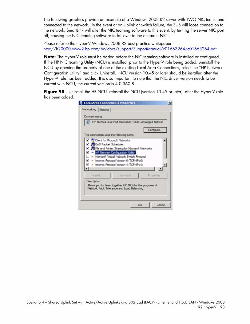
Scenario 4 – Shared Uplink Set with Active/Active Uplinks and 802.3ad (LACP) - Ethernet and FCoE SAN - Windows 2008 R2 Hyper-V 93
The following graphics provide an example of a Windows 2008 R2 server with TWO NIC teams and connected to the network. In the event of an Uplink or switch failure, the SUS will loose connection to the network; SmartLink will alter the NIC teaming software to this event, by turning the server NIC port off, causing the NIC teaming software to fail-over to the alternate NIC.
Please refer to the Hyper-V Windows 2008 R2 best practice whitepaper - http://h20000.www2.hp.com/bc/docs/support/SupportManual/c01663264/c01663264.pdf
Note: The Hyper-V role must be added before the NIC teaming software is installed or configured. If the HP NIC teaming Utility (NCU) is installed, prior to the Hyper-V role being added, uninstall the NCU by opening the property of one of the existing Local Area Connections, select the “HP Network Configuration Utility” and click Uninstall. NCU version 10.45 or later should be installed after the Hyper-V role has been added. It is also important to note that the NIC driver version needs to be current with NCU, the current version is 4.0.360.8.
Figure 98 - Uninstall the HP NCU, reinstall the NCU (version 10.45 or later), after the Hyper-V role has been added.
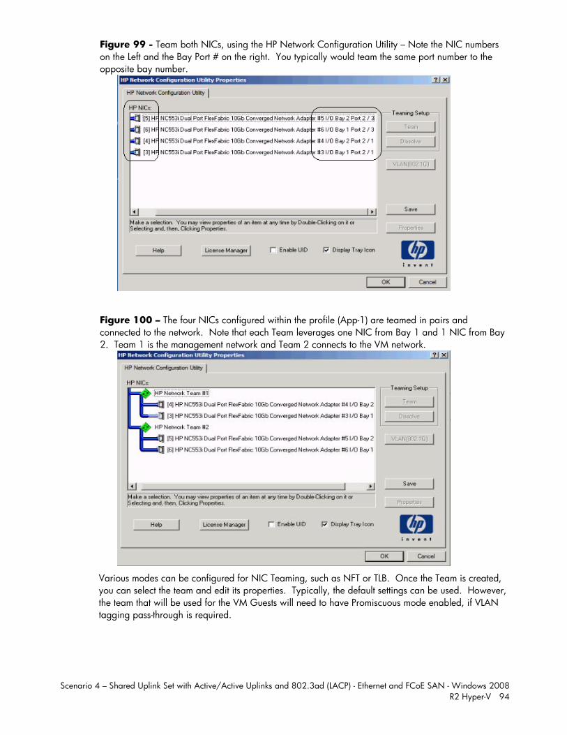
Scenario 4 – Shared Uplink Set with Active/Active Uplinks and 802.3ad (LACP) - Ethernet and FCoE SAN - Windows 2008 R2 Hyper-V 94
Figure 99 - Team both NICs, using the HP Network Configuration Utility – Note the NIC numbers on the Left and the Bay Port # on the right. You typically would team the same port number to the opposite bay number.
Figure 100 – The four NICs configured within the profile (App-1) are teamed in pairs and connected to the network. Note that each Team leverages one NIC from Bay 1 and 1 NIC from Bay 2. Team 1 is the management network and Team 2 connects to the VM network.
Various modes can be configured for NIC Teaming, such as NFT or TLB. Once the Team is created, you can select the team and edit its properties. Typically, the default settings can be used. However, the team that will be used for the VM Guests will need to have Promiscuous mode enabled, if VLAN tagging pass-through is required.
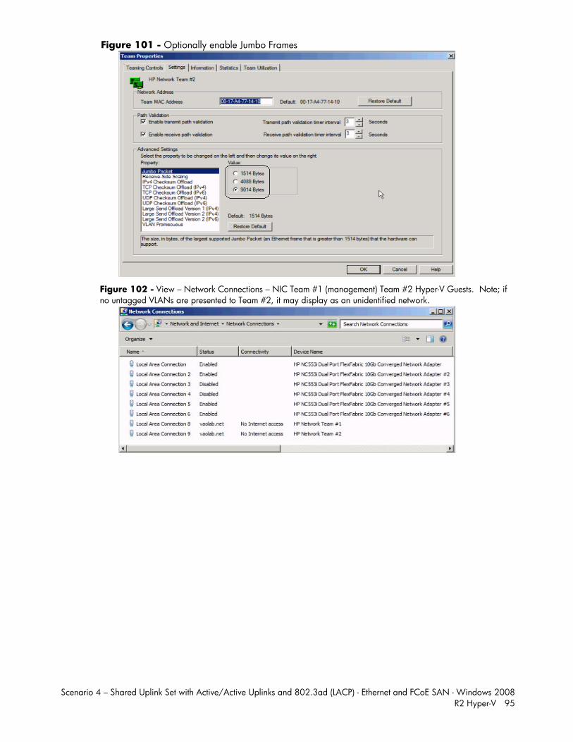
Scenario 4 – Shared Uplink Set with Active/Active Uplinks and 802.3ad (LACP) - Ethernet and FCoE SAN - Windows 2008 R2 Hyper-V 95
Figure 101 - Optionally enable Jumbo Frames
Figure 102 - View – Network Connections – NIC Team #1 (management) Team #2 Hyper-V Guests. Note; if no untagged VLANs are presented to Team #2, it may display as an unidentified network.
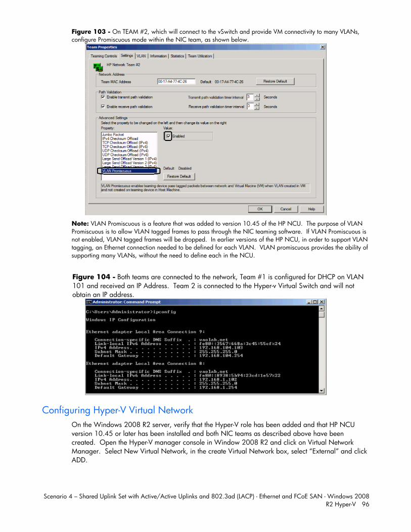
Scenario 4 – Shared Uplink Set with Active/Active Uplinks and 802.3ad (LACP) - Ethernet and FCoE SAN - Windows 2008 R2 Hyper-V 96
Figure 103 - On TEAM #2, which will connect to the vSwitch and provide VM connectivity to many VLANs, configure Promiscuous mode within the NIC team, as shown below.
Note: VLAN Promiscuous is a feature that was added to version 10.45 of the HP NCU. The purpose of VLAN Promiscuous is to allow VLAN tagged frames to pass through the NIC teaming software. If VLAN Promiscuous is not enabled, VLAN tagged frames will be dropped. In earlier versions of the HP NCU, in order to support VLAN tagging, an Ethernet connection needed to be defined for each VLAN. VLAN promiscuous provides the ability of supporting many VLANs, without the need to define each in the NCU.
Figure 104 - Both teams are connected to the network, Team #1 is configured for DHCP on VLAN 101 and received an IP Address. Team 2 is connected to the Hyper-v Virtual Switch and will not obtain an IP address.
Configuring Hyper-V Virtual Network On the Windows 2008 R2 server, verify that the Hyper-V role has been added and that HP NCU version 10.45 or later has been installed and both NIC teams as described above have been created. Open the Hyper-V manager console in Window 2008 R2 and click on Virtual Network Manager. Select New Virtual Network, in the create Virtual Network box, select “External” and click ADD.
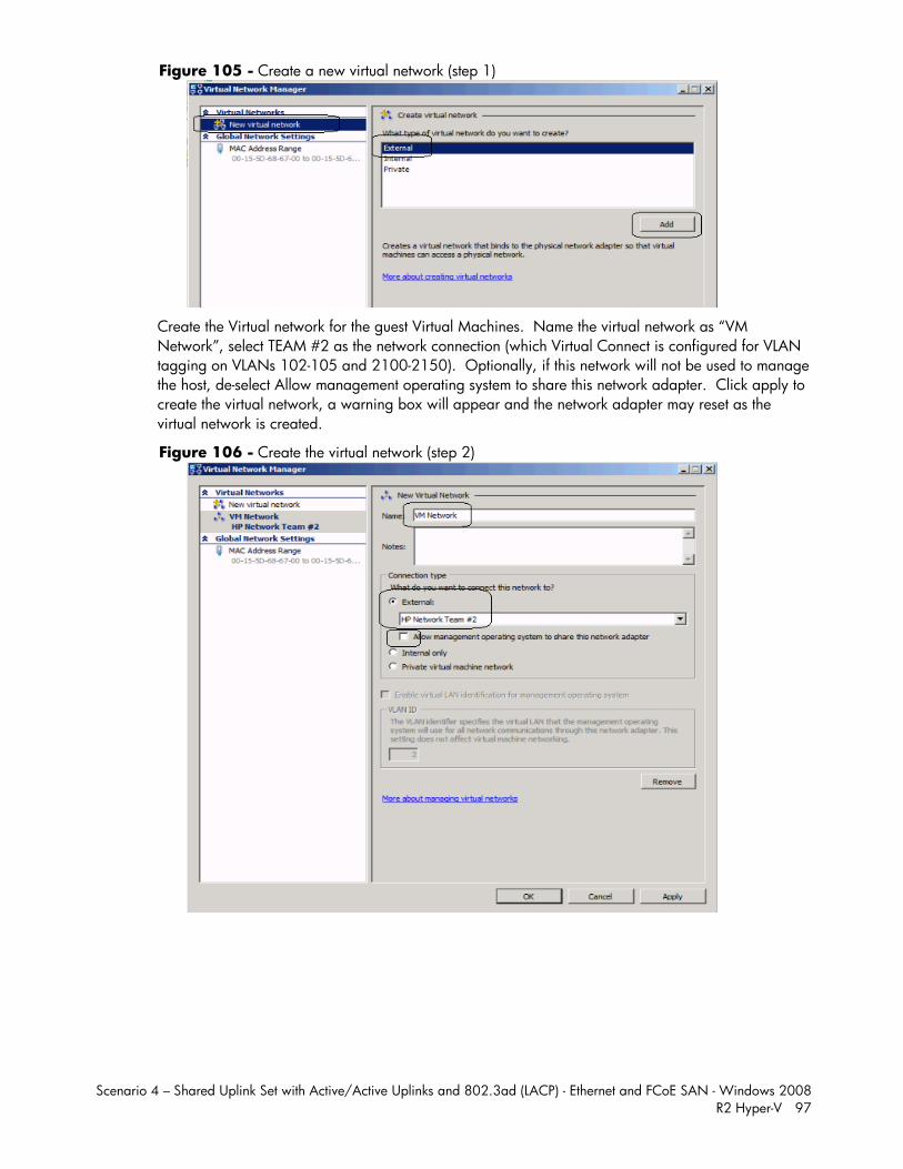
Scenario 4 – Shared Uplink Set with Active/Active Uplinks and 802.3ad (LACP) - Ethernet and FCoE SAN - Windows 2008 R2 Hyper-V 97
Figure 105 - Create a new virtual network (step 1)
Create the Virtual network for the guest Virtual Machines. Name the virtual network as “VM Network”, select TEAM #2 as the network connection (which Virtual Connect is configured for VLAN tagging on VLANs 102-105 and 2100-2150). Optionally, if this network will not be used to manage the host, de-select Allow management operating system to share this network adapter. Click apply to create the virtual network, a warning box will appear and the network adapter may reset as the virtual network is created.
Figure 106 - Create the virtual network (step 2)
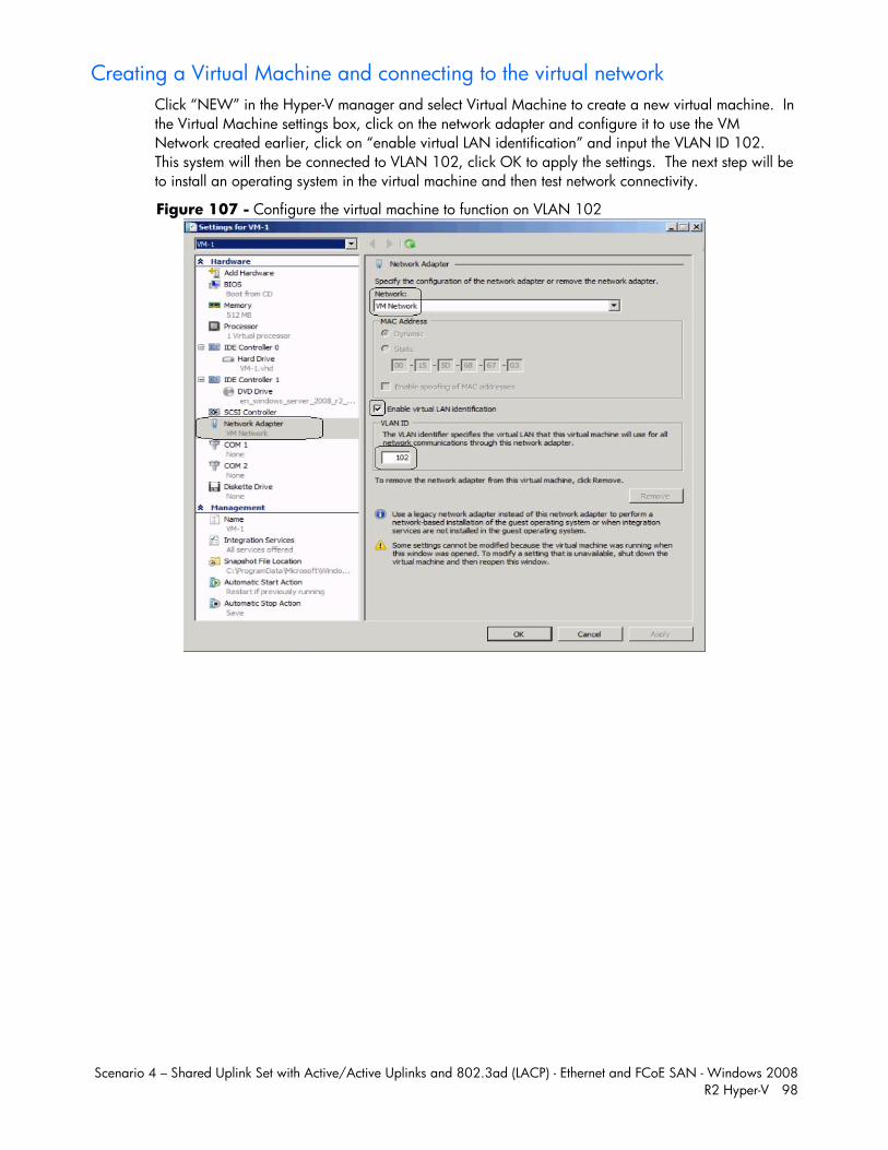
Scenario 4 – Shared Uplink Set with Active/Active Uplinks and 802.3ad (LACP) - Ethernet and FCoE SAN - Windows 2008 R2 Hyper-V 98
Creating a Virtual Machine and connecting to the virtual network Click “NEW” in the Hyper-V manager and select Virtual Machine to create a new virtual machine. In the Virtual Machine settings box, click on the network adapter and configure it to use the VM Network created earlier, click on “enable virtual LAN identification” and input the VLAN ID 102. This system will then be connected to VLAN 102, click OK to apply the settings. The next step will be to install an operating system in the virtual machine and then test network connectivity.
Figure 107 - Configure the virtual machine to function on VLAN 102
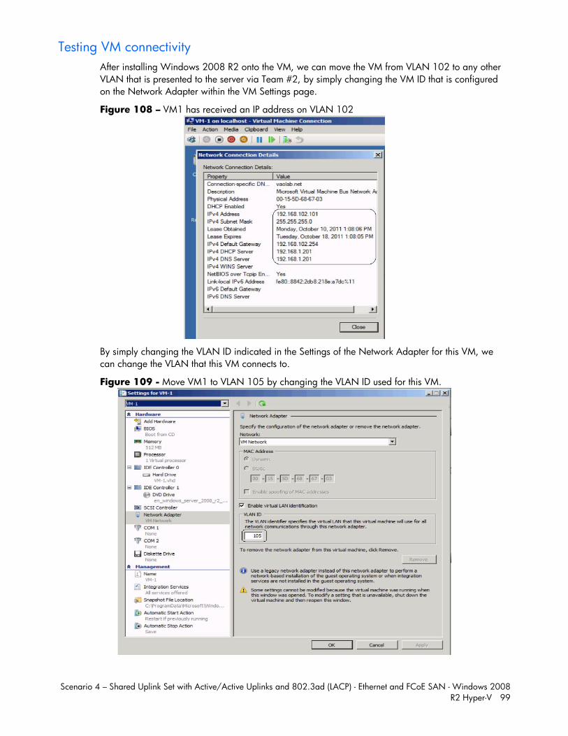
Scenario 4 – Shared Uplink Set with Active/Active Uplinks and 802.3ad (LACP) - Ethernet and FCoE SAN - Windows 2008 R2 Hyper-V 99
Testing VM connectivity After installing Windows 2008 R2 onto the VM, we can move the VM from VLAN 102 to any other VLAN that is presented to the server via Team #2, by simply changing the VM ID that is configured on the Network Adapter within the VM Settings page.
Figure 108 – VM1 has received an IP address on VLAN 102
By simply changing the VLAN ID indicated in the Settings of the Network Adapter for this VM, we can change the VLAN that this VM connects to.
Figure 109 - Move VM1 to VLAN 105 by changing the VLAN ID used for this VM.
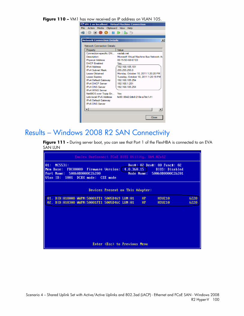
Scenario 4 – Shared Uplink Set with Active/Active Uplinks and 802.3ad (LACP) - Ethernet and FCoE SAN - Windows 2008 R2 Hyper-V 100
Figure 110 – VM1 has now received an IP address on VLAN 105.
Results – Windows 2008 R2 SAN Connectivity Figure 111 - During server boot, you can see that Port 1 of the FlexHBA is connected to an EVA SAN LUN
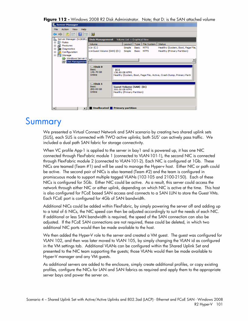
Scenario 4 – Shared Uplink Set with Active/Active Uplinks and 802.3ad (LACP) - Ethernet and FCoE SAN - Windows 2008 R2 Hyper-V 101
Figure 112 - Windows 2008 R2 Disk Administrator. Note; that D: is the SAN attached volume
Summary We presented a Virtual Connect Network and SAN scenario by creating two shared uplink sets (SUS), each SUS is connected with TWO active uplinks; both SUS’ can actively pass traffic. We included a dual path SAN fabric for storage connectivity.
When VC profile App-1 is applied to the server in bay1 and is powered up, it has one NIC connected through FlexFabric module 1 (connected to VLAN-101-1), the second NIC is connected through FlexFabric module 2 (connected to VLAN-101-2). Each NIC is configured at 1Gb. These NICs are teamed (Team #1) and will be used to manage the Hyper-v host. Either NIC or path could be active. The second pair of NICs is also teamed (Team #2) and the team is configured in promiscuous mode to support multiple tagged VLANs (102-105 and 2100-2150). Each of these NICs is configured for 5Gb. Either NIC could be active. As a result, this server could access the network through either NIC or either uplink, depending on which NIC is active at the time. This host is also configured for FCoE based SAN access and connects to a SAN LUN to store the Guest VMs. Each FCoE port is configured for 4Gb of SAN bandwidth.
Additional NICs could be added within FlexFabric, by simply powering the server off and adding up to a total of 6 NICs, the NIC speed can then be adjusted accordingly to suit the needs of each NIC. If additional or less SAN bandwidth is required, the speed of the SAN connection can also be adjusted. If the FCoE SAN connections are not required, these could be deleted, in which two additional NIC ports would then be made available to the host.
We then added the Hyper-V role to the server and created a VM guest. The guest was configured for VLAN 102, and then was later moved to VLAN 105, by simply changing the VLAN id as configured in the VM settings tab. Additional VLANs can be configured within the Shared Uplink Set and presented to the NIC team supporting the guests; those VLANs would then be made available to Hyper-V manager and any VM guests.
As additional servers are added to the enclosure, simply create additional profiles, or copy existing profiles, configure the NICs for LAN and SAN fabrics as required and apply them to the appropriate server bays and power the server on.
Scenario 5 – Shared Uplink Set with Active/Standby Uplinks and 802.3ad (LACP) - Ethernet and FCoE SAN - vSphere 102
Scenario 5 – Shared Uplink Set with Active/Standby Uplinks and 802.3ad (LACP) - Ethernet and FCoE SAN - vSphere
Overview This scenario will implement the Shared Uplink Set (SUS) to provide support for multiple VLANs. In this scenario, the upstream network switches connect a shared uplink set to two ports on each FlexFabric modules, LACP will be used to aggregate those links.
As multiple VLANs will be supported in this configuration, the upstream switch ports connecting to the FlexFabric modules will be configured to properly present those VLANs. In this scenario, the upstream switch ports will be configured for VLAN trunking/VLAN tagging.
When configuring Virtual Connect, we can provide several ways to implement network fail-over or redundancy. One option would be to connect multiple uplinks to a single virtual connect network; those uplinks would connect from different Virtual Connect modules within the enclosure and could then connect to the same upstream switch or two different upstream switches, depending on your redundancy needs. An alternative would be to configure TWO separate Virtual Connect networks, each with a single, or multiple, uplinks configured. Each option has its advantages and disadvantages. For example; an Active/Standby configuration places the redundancy at the VC level, where Active/Active places it at the OS NIC teaming or bonding level. We will review the first option in this scenario.
In addition, several Virtual Connect Networks can be configured to support the required networks to the servers within the BladeSystem enclosure. These networks could be used to separate the various network traffic types, such as iSCSI, backup and VMotion from production network traffic.
This scenario will also leverage the Fibre Channel over Ethernet (FCoE) capabilities of the FlexFabric modules. Each Fibre channel fabric will have two uplinks connected to each of the FlexFabric modules.
Requirements This scenario will support both Ethernet and fibre channel connectivity. In order to implement this scenario, an HP BladeSystem c7000 enclosure with one or more server blades and TWO Virtual Connect FlexFabric modules, installed in I/O Bays 1& 2 are required. In addition, we will require ONE or TWO external Network switches. As Virtual Connect does not appear to the network as a switch and is transparent to the network, any standard managed switch will work with Virtual Connect. The Fibre Channel uplinks will connect to the existing FC SAN fabrics. The SAN switch ports will need to be configured to support NPIV logins. Two uplinks from each FlexFabric module will be connected to the existing SAN fabrics.
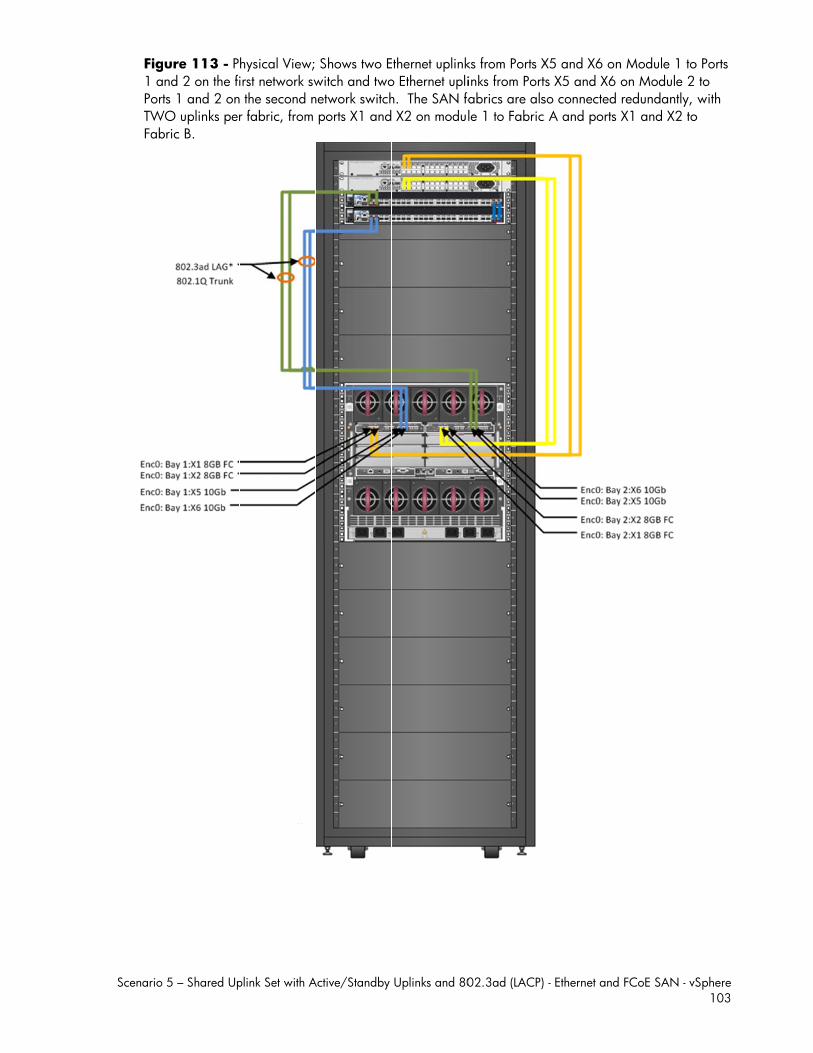
Scenario
Fig1 aPortTWFab
5 – Shared Up
ure 113 - Pnd 2 on the fits 1 and 2 on
WO uplinks perbric B.
plink Set with A
hysical View; irst network sw the second nr fabric, from
Active/Standby
Shows two Ewitch and twonetwork switch ports X1 and
Uplinks and 80
Ethernet uplinko Ethernet uplih. The SAN fa X2 on modu
02.3ad (LACP)
ks from Ports Xinks from Portabrics are alsle 1 to Fabric
- Ethernet and
X5 and X6 onts X5 and X6 so connected c A and ports
FCoE SAN - vS
n Module 1 toon Module 2 redundantly, X1 and X2 to
Sphere 103
o Ports to with o
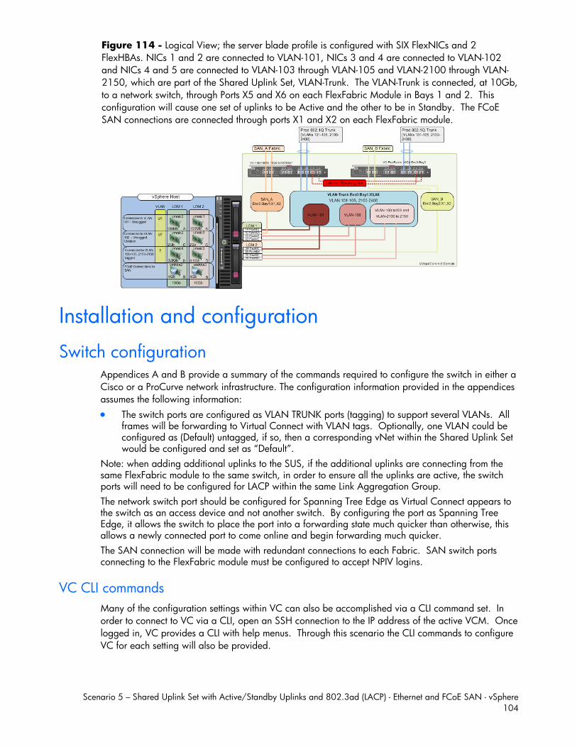
Scenario 5 – Shared Uplink Set with Active/Standby Uplinks and 802.3ad (LACP) - Ethernet and FCoE SAN - vSphere 104
Figure 114 - Logical View; the server blade profile is configured with SIX FlexNICs and 2 FlexHBAs. NICs 1 and 2 are connected to VLAN-101, NICs 3 and 4 are connected to VLAN-102 and NICs 4 and 5 are connected to VLAN-103 through VLAN-105 and VLAN-2100 through VLAN-2150, which are part of the Shared Uplink Set, VLAN-Trunk. The VLAN-Trunk is connected, at 10Gb, to a network switch, through Ports X5 and X6 on each FlexFabric Module in Bays 1 and 2. This configuration will cause one set of uplinks to be Active and the other to be in Standby. The FCoE SAN connections are connected through ports X1 and X2 on each FlexFabric module.
Installation and configuration
Switch configuration Appendices A and B provide a summary of the commands required to configure the switch in either a Cisco or a ProCurve network infrastructure. The configuration information provided in the appendices assumes the following information: The switch ports are configured as VLAN TRUNK ports (tagging) to support several VLANs. All
frames will be forwarding to Virtual Connect with VLAN tags. Optionally, one VLAN could be configured as (Default) untagged, if so, then a corresponding vNet within the Shared Uplink Set would be configured and set as “Default”.
Note: when adding additional uplinks to the SUS, if the additional uplinks are connecting from the same FlexFabric module to the same switch, in order to ensure all the uplinks are active, the switch ports will need to be configured for LACP within the same Link Aggregation Group. The network switch port should be configured for Spanning Tree Edge as Virtual Connect appears to the switch as an access device and not another switch. By configuring the port as Spanning Tree Edge, it allows the switch to place the port into a forwarding state much quicker than otherwise, this allows a newly connected port to come online and begin forwarding much quicker. The SAN connection will be made with redundant connections to each Fabric. SAN switch ports connecting to the FlexFabric module must be configured to accept NPIV logins.
VC CLI commands Many of the configuration settings within VC can also be accomplished via a CLI command set. In order to connect to VC via a CLI, open an SSH connection to the IP address of the active VCM. Once logged in, VC provides a CLI with help menus. Through this scenario the CLI commands to configure VC for each setting will also be provided.
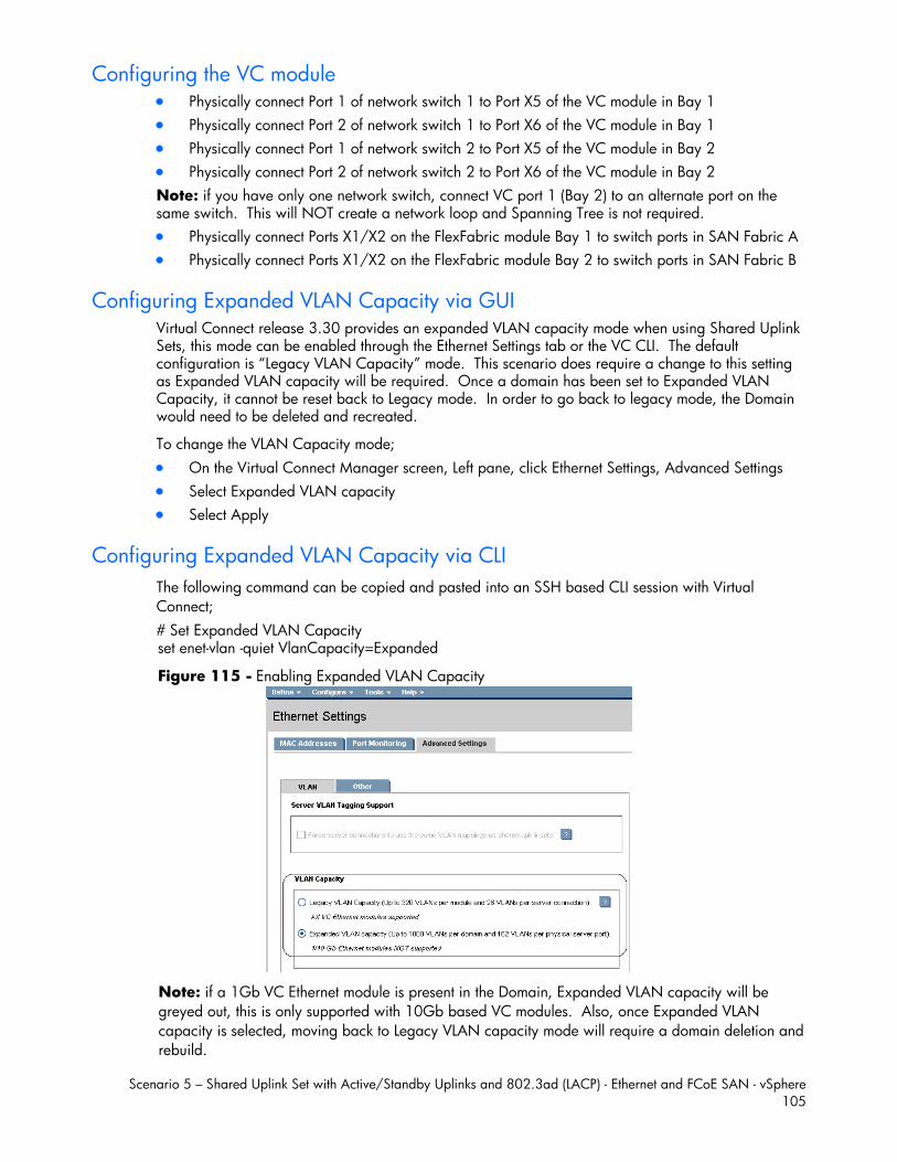
Scenario 5 – Shared Uplink Set with Active/Standby Uplinks and 802.3ad (LACP) - Ethernet and FCoE SAN - vSphere 105
Configuring the VC module Physically connect Port 1 of network switch 1 to Port X5 of the VC module in Bay 1 Physically connect Port 2 of network switch 1 to Port X6 of the VC module in Bay 1 Physically connect Port 1 of network switch 2 to Port X5 of the VC module in Bay 2 Physically connect Port 2 of network switch 2 to Port X6 of the VC module in Bay 2 Note: if you have only one network switch, connect VC port 1 (Bay 2) to an alternate port on the same switch. This will NOT create a network loop and Spanning Tree is not required. Physically connect Ports X1/X2 on the FlexFabric module Bay 1 to switch ports in SAN Fabric A Physically connect Ports X1/X2 on the FlexFabric module Bay 2 to switch ports in SAN Fabric B
Configuring Expanded VLAN Capacity via GUI Virtual Connect release 3.30 provides an expanded VLAN capacity mode when using Shared Uplink Sets, this mode can be enabled through the Ethernet Settings tab or the VC CLI. The default configuration is “Legacy VLAN Capacity” mode. This scenario does require a change to this setting as Expanded VLAN capacity will be required. Once a domain has been set to Expanded VLAN Capacity, it cannot be reset back to Legacy mode. In order to go back to legacy mode, the Domain would need to be deleted and recreated.
To change the VLAN Capacity mode; On the Virtual Connect Manager screen, Left pane, click Ethernet Settings, Advanced Settings Select Expanded VLAN capacity Select Apply
Configuring Expanded VLAN Capacity via CLI The following command can be copied and pasted into an SSH based CLI session with Virtual Connect; # Set Expanded VLAN Capacity set enet-vlan -quiet VlanCapacity=Expanded
Figure 115 - Enabling Expanded VLAN Capacity
Note: if a 1Gb VC Ethernet module is present in the Domain, Expanded VLAN capacity will be greyed out, this is only supported with 10Gb based VC modules. Also, once Expanded VLAN capacity is selected, moving back to Legacy VLAN capacity mode will require a domain deletion and rebuild.
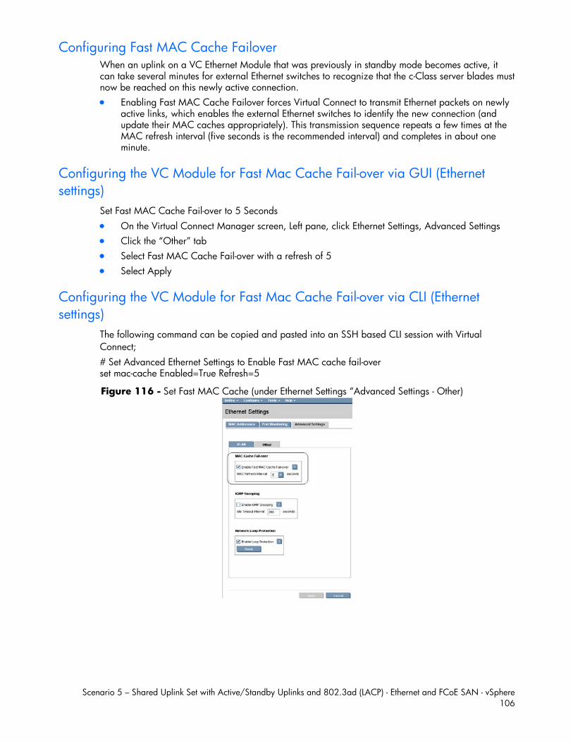
Scenario 5 – Shared Uplink Set with Active/Standby Uplinks and 802.3ad (LACP) - Ethernet and FCoE SAN - vSphere 106
Configuring Fast MAC Cache Failover When an uplink on a VC Ethernet Module that was previously in standby mode becomes active, it can take several minutes for external Ethernet switches to recognize that the c-Class server blades must now be reached on this newly active connection. Enabling Fast MAC Cache Failover forces Virtual Connect to transmit Ethernet packets on newly
active links, which enables the external Ethernet switches to identify the new connection (and update their MAC caches appropriately). This transmission sequence repeats a few times at the MAC refresh interval (five seconds is the recommended interval) and completes in about one minute.
Configuring the VC Module for Fast Mac Cache Fail-over via GUI (Ethernet settings)
Set Fast MAC Cache Fail-over to 5 Seconds On the Virtual Connect Manager screen, Left pane, click Ethernet Settings, Advanced Settings Click the “Other” tab Select Fast MAC Cache Fail-over with a refresh of 5 Select Apply
Configuring the VC Module for Fast Mac Cache Fail-over via CLI (Ethernet settings)
The following command can be copied and pasted into an SSH based CLI session with Virtual Connect; # Set Advanced Ethernet Settings to Enable Fast MAC cache fail-over set mac-cache Enabled=True Refresh=5
Figure 116 - Set Fast MAC Cache (under Ethernet Settings “Advanced Settings - Other)
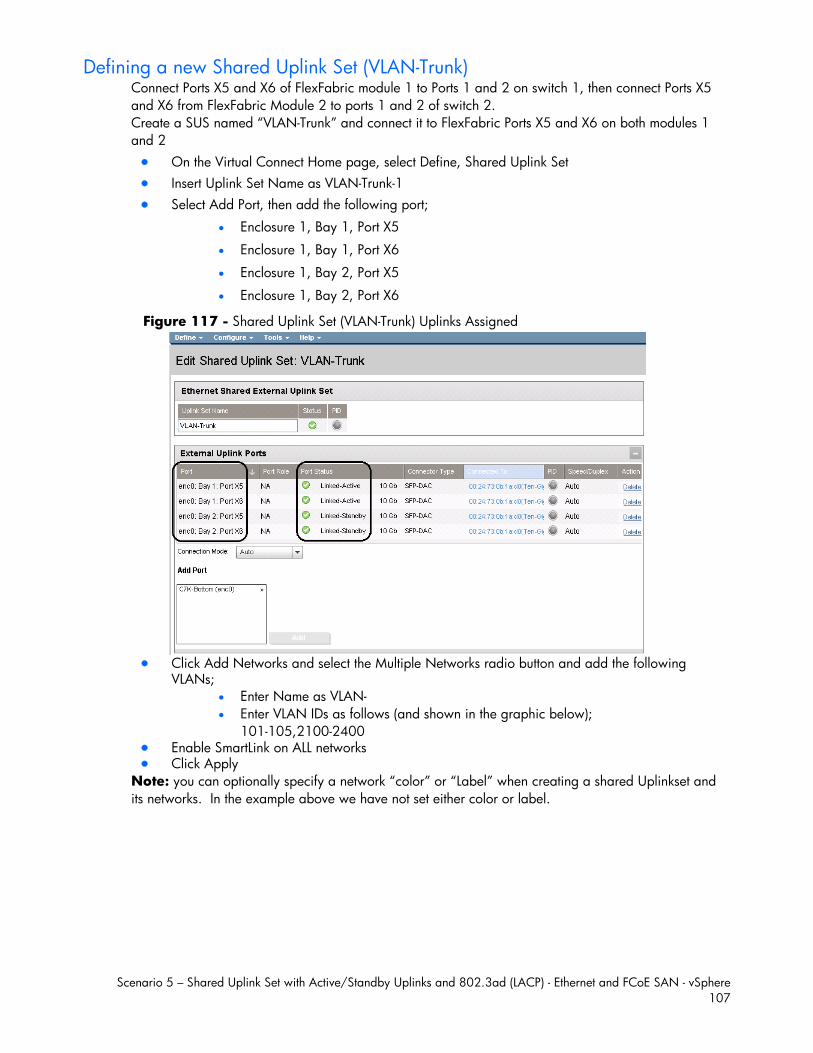
Scenario 5 – Shared Uplink Set with Active/Standby Uplinks and 802.3ad (LACP) - Ethernet and FCoE SAN - vSphere 107
Defining a new Shared Uplink Set (VLAN-Trunk) Connect Ports X5 and X6 of FlexFabric module 1 to Ports 1 and 2 on switch 1, then connect Ports X5 and X6 from FlexFabric Module 2 to ports 1 and 2 of switch 2. Create a SUS named “VLAN-Trunk” and connect it to FlexFabric Ports X5 and X6 on both modules 1 and 2 On the Virtual Connect Home page, select Define, Shared Uplink Set Insert Uplink Set Name as VLAN-Trunk-1 Select Add Port, then add the following port;
Enclosure 1, Bay 1, Port X5
Enclosure 1, Bay 1, Port X6
Enclosure 1, Bay 2, Port X5
Enclosure 1, Bay 2, Port X6
Figure 117 - Shared Uplink Set (VLAN-Trunk) Uplinks Assigned
Click Add Networks and select the Multiple Networks radio button and add the following
VLANs; Enter Name as VLAN- Enter VLAN IDs as follows (and shown in the graphic below);
101-105,2100-2400 Enable SmartLink on ALL networks Click Apply
Note: you can optionally specify a network “color” or “Label” when creating a shared Uplinkset and its networks. In the example above we have not set either color or label.
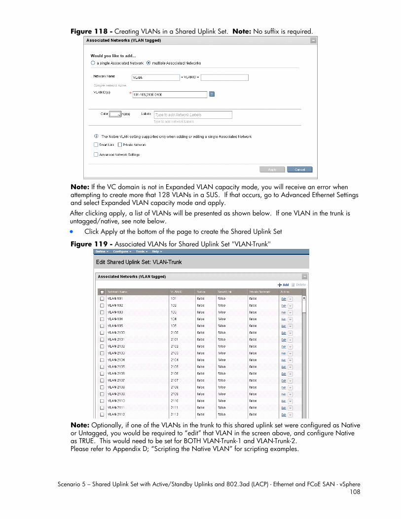
Scenario 5 – Shared Uplink Set with Active/Standby Uplinks and 802.3ad (LACP) - Ethernet and FCoE SAN - vSphere 108
Figure 118 - Creating VLANs in a Shared Uplink Set. Note: No suffix is required.
Note: If the VC domain is not in Expanded VLAN capacity mode, you will receive an error when attempting to create more that 128 VLANs in a SUS. If that occurs, go to Advanced Ethernet Settings and select Expanded VLAN capacity mode and apply. After clicking apply, a list of VLANs will be presented as shown below. If one VLAN in the trunk is untagged/native, see note below. Click Apply at the bottom of the page to create the Shared Uplink Set
Figure 119 - Associated VLANs for Shared Uplink Set "VLAN-Trunk"
Note: Optionally, if one of the VLANs in the trunk to this shared uplink set were configured as Native or Untagged, you would be required to “edit” that VLAN in the screen above, and configure Native as TRUE. This would need to be set for BOTH VLAN-Trunk-1 and VLAN-Trunk-2. Please refer to Appendix D; “Scripting the Native VLAN” for scripting examples.
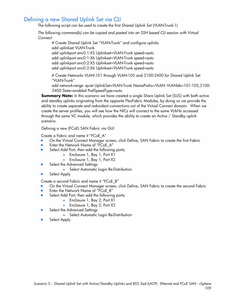
Scenario 5 – Shared Uplink Set with Active/Standby Uplinks and 802.3ad (LACP) - Ethernet and FCoE SAN - vSphere 109
Defining a new Shared Uplink Set via CLI The following script can be used to create the first Shared Uplink Set (VLAN-Trunk-1)
The following command(s) can be copied and pasted into an SSH based CLI session with Virtual Connect
# Create Shared Uplink Set "VLAN-Trunk" and configure uplinks add uplinkset VLAN-Trunk add uplinkport enc0:1:X5 Uplinkset=VLAN-Trunk speed=auto add uplinkport enc0:1:X6 Uplinkset=VLAN-Trunk speed=auto add uplinkport enc0:2:X5 Uplinkset=VLAN-Trunk speed=auto add uplinkport enc0:2:X6 Uplinkset=VLAN-Trunk speed=auto
# Create Networks VLAN-101 through VLAN-105 and 2100-2400 for Shared Uplink Set "VLAN-Trunk" add network-range -quiet UplinkSet=VLAN-Trunk NamePrefix=VLAN- VLANIds=101-105,2100-2400 State=enabled PrefSpeedType=auto
Summary Note: In this scenario we have created a single Share Uplink Set (SUS) with both active and standby uplinks originating from the opposite FlexFabric Modules, by doing so we provide the ability to create separate and redundant connections out of the Virtual Connect domain. When we create the server profiles, you will see how the NICs will connect to the same VLANs accessed through the same VC module, which provides the ability to create an Active / Standby uplink scenario.
Defining a new (FCoE) SAN Fabric via GUI
Create a Fabric and name it “FCoE_A” On the Virtual Connect Manager screen, click Define, SAN Fabric to create the first Fabric Enter the Network Name of “FCoE_A” Select Add Port, then add the following ports;
Enclosure 1, Bay 1, Port X1 Enclosure 1, Bay 1, Port X2
Select the Advanced Settings Select Automatic Login Re-Distribution
Select Apply
Create a second Fabric and name it “FCoE_B” On the Virtual Connect Manager screen, click Define, SAN Fabric to create the second Fabric Enter the Network Name of “FCoE_B” Select Add Port, then add the following ports;
Enclosure 1, Bay 2, Port X1 Enclosure 1, Bay 2, Port X2
Select the Advanced Settings Select Automatic Login Re-Distribution
Select Apply
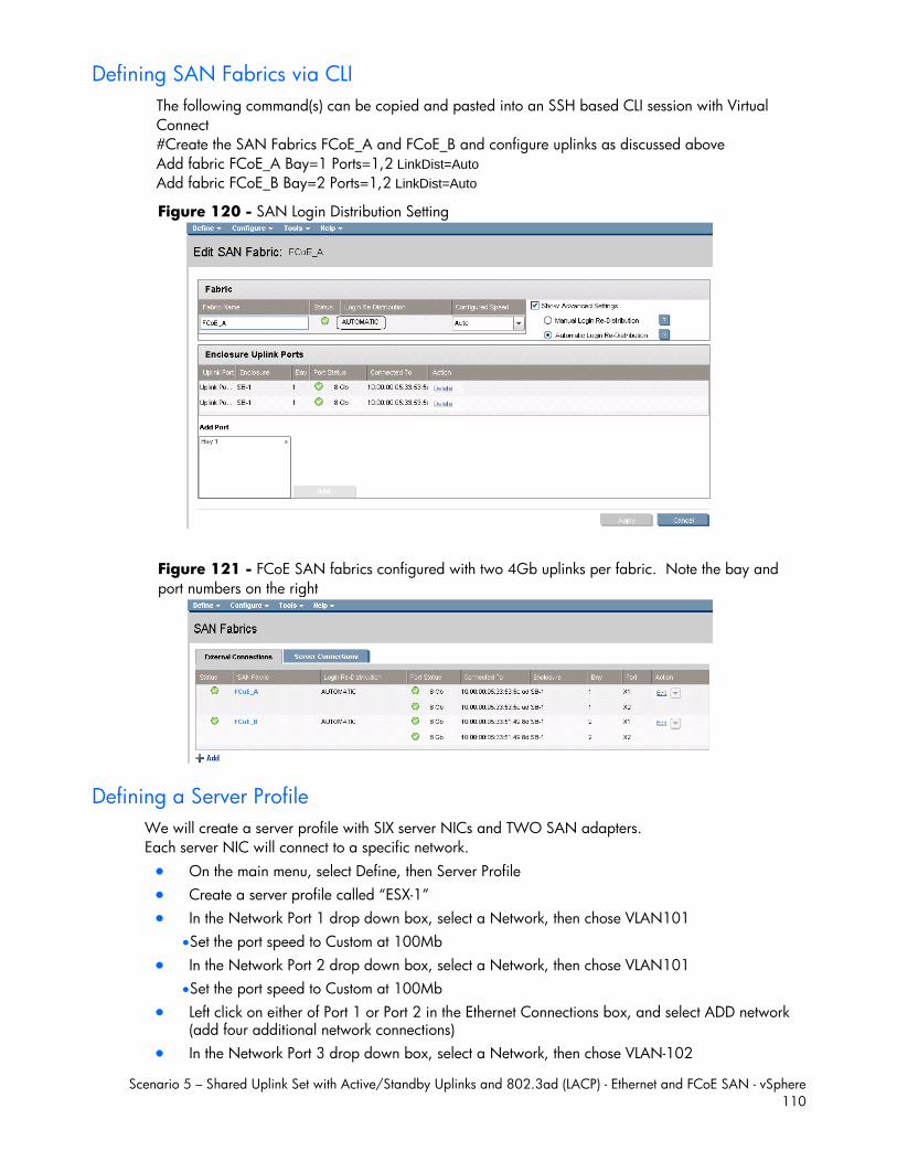
Scenario 5 – Shared Uplink Set with Active/Standby Uplinks and 802.3ad (LACP) - Ethernet and FCoE SAN - vSphere 110
Defining SAN Fabrics via CLI The following command(s) can be copied and pasted into an SSH based CLI session with Virtual Connect #Create the SAN Fabrics FCoE_A and FCoE_B and configure uplinks as discussed above Add fabric FCoE_A Bay=1 Ports=1,2 LinkDist=Auto Add fabric FCoE_B Bay=2 Ports=1,2 LinkDist=Auto
Figure 120 - SAN Login Distribution Setting
Figure 121 - FCoE SAN fabrics configured with two 4Gb uplinks per fabric. Note the bay and port numbers on the right
Defining a Server Profile We will create a server profile with SIX server NICs and TWO SAN adapters. Each server NIC will connect to a specific network. On the main menu, select Define, then Server Profile Create a server profile called “ESX-1” In the Network Port 1 drop down box, select a Network, then chose VLAN101
Set the port speed to Custom at 100Mb In the Network Port 2 drop down box, select a Network, then chose VLAN101
Set the port speed to Custom at 100Mb Left click on either of Port 1 or Port 2 in the Ethernet Connections box, and select ADD network
(add four additional network connections) In the Network Port 3 drop down box, select a Network, then chose VLAN-102
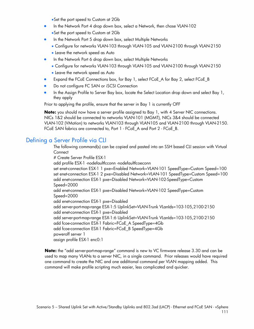
Scenario 5 – Shared Uplink Set with Active/Standby Uplinks and 802.3ad (LACP) - Ethernet and FCoE SAN - vSphere 111
Set the port speed to Custom at 2Gb In the Network Port 4 drop down box, select a Network, then chose VLAN-102
Set the port speed to Custom at 2Gb In the Network Port 5 drop down box, select Multiple Networks
Configure for networks VLAN-103 through VLAN-105 and VLAN-2100 through VLAN-2150 Leave the network speed as Auto
In the Network Port 6 drop down box, select Multiple Networks Configure for networks VLAN-103 through VLAN-105 and VLAN-2100 through VLAN-2150 Leave the network speed as Auto
Expand the FCoE Connections box, for Bay 1, select FCoE_A for Bay 2, select FCoE_B Do not configure FC SAN or iSCSI Connection In the Assign Profile to Server Bay box, locate the Select Location drop down and select Bay 1,
they apply Prior to applying the profile, ensure that the server in Bay 1 is currently OFF
Note: you should now have a server profile assigned to Bay 1, with 4 Server NIC connections. NICs 1&2 should be connected to networks VLAN-101 (MGMT), NICs 3&4 should be connected VLAN-102 (VMotion) to networks VLAN103 through VLAN105 and VLAN-2100 through VLAN-2150. FCoE SAN fabrics are connected to, Port 1 - FCoE_A and Port 2 - FCoE_B.
Defining a Server Profile via CLI The following command(s) can be copied and pasted into an SSH based CLI session with Virtual Connect # Create Server Profile ESX-1 add profile ESX-1 -nodefaultfcconn -nodefaultfcoeconn set enet-connection ESX-1 1 pxe=Enabled Network=VLAN-101 SpeedType=Custom Speed=100 set enet-connection ESX-1 2 pxe=Disabled Network=VLAN-101 SpeedType=Custom Speed=100 add enet-connection ESX-1 pxe=Disabled Network=VLAN-102-SpeedType=Custom Speed=2000 add enet-connection ESX-1 pxe=Disabled Network=VLAN-102 SpeedType=Custom Speed=2000 add enet-connection ESX-1 pxe=Disabled add server-port-map-range ESX-1:5 UplinkSet=VLAN-Trunk VLanIds=103-105,2100-2150 add enet-connection ESX-1 pxe=Disabled add server-port-map-range ESX-1:6 UplinkSet=VLAN-Trunk VLanIds=103-105,2100-2150 add fcoe-connection ESX-1 Fabric=FCoE_A SpeedType=4Gb add fcoe-connection ESX-1 Fabric=FCoE_B SpeedType=4Gb poweroff server 1 assign profile ESX-1 enc0:1
Note: the “add server-port-map-range” command is new to VC firmware release 3.30 and can be used to map many VLANs to a server NIC, in a single command. Prior releases would have required one command to create the NIC and one additional command per VLAN mapping added. This command will make profile scripting much easier, less complicated and quicker.
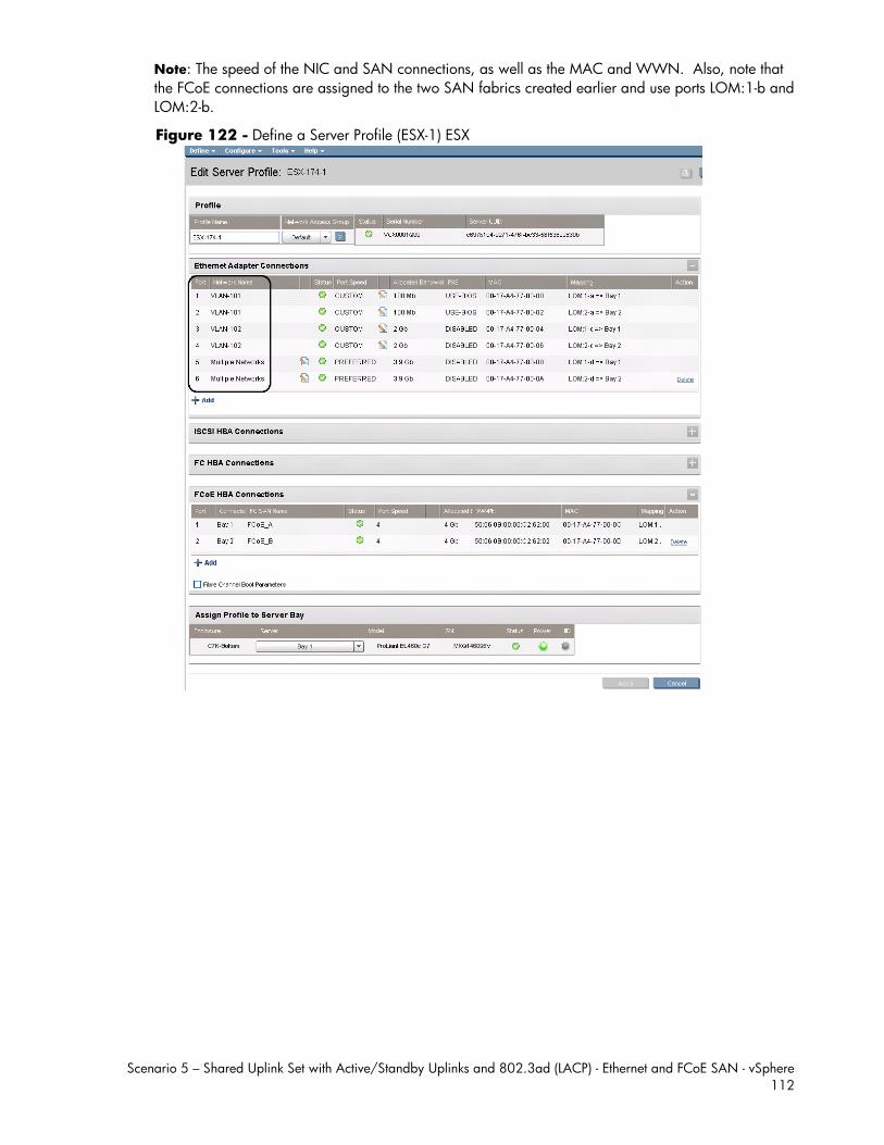
Scenario 5 – Shared Uplink Set with Active/Standby Uplinks and 802.3ad (LACP) - Ethernet and FCoE SAN - vSphere 112
Note: The speed of the NIC and SAN connections, as well as the MAC and WWN. Also, note that the FCoE connections are assigned to the two SAN fabrics created earlier and use ports LOM:1-b and LOM:2-b.
Figure 122 - Define a Server Profile (ESX-1) ESX
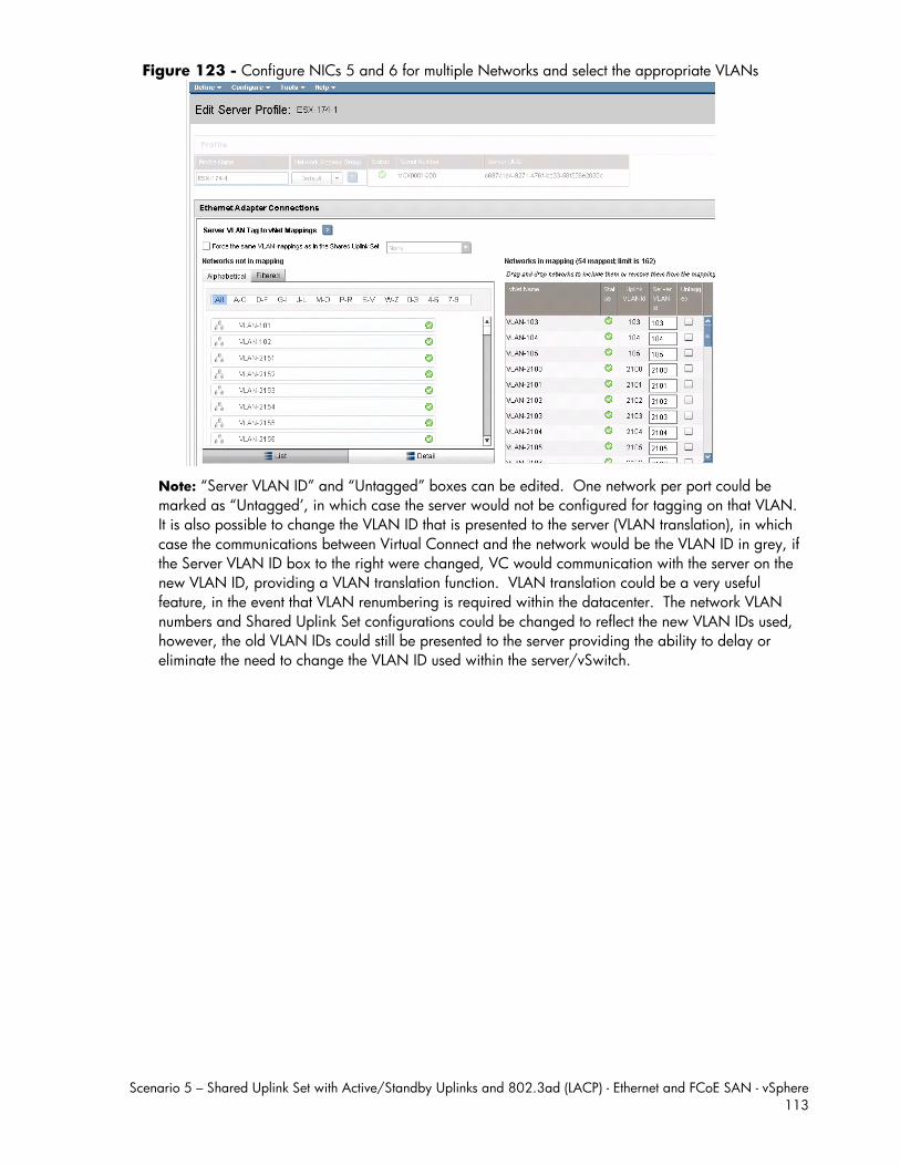
Scenario 5 – Shared Uplink Set with Active/Standby Uplinks and 802.3ad (LACP) - Ethernet and FCoE SAN - vSphere 113
Figure 123 - Configure NICs 5 and 6 for multiple Networks and select the appropriate VLANs
Note: “Server VLAN ID” and “Untagged” boxes can be edited. One network per port could be marked as “Untagged’, in which case the server would not be configured for tagging on that VLAN. It is also possible to change the VLAN ID that is presented to the server (VLAN translation), in which case the communications between Virtual Connect and the network would be the VLAN ID in grey, if the Server VLAN ID box to the right were changed, VC would communication with the server on the new VLAN ID, providing a VLAN translation function. VLAN translation could be a very useful feature, in the event that VLAN renumbering is required within the datacenter. The network VLAN numbers and Shared Uplink Set configurations could be changed to reflect the new VLAN IDs used, however, the old VLAN IDs could still be presented to the server providing the ability to delay or eliminate the need to change the VLAN ID used within the server/vSwitch.
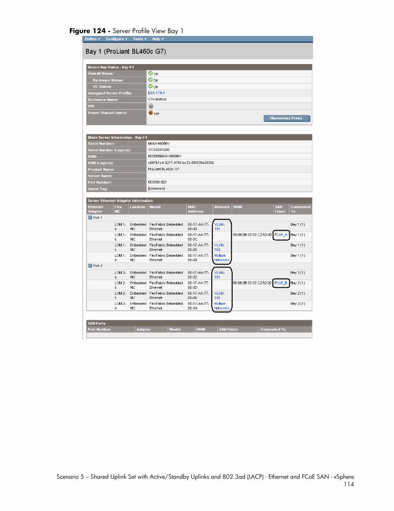
Scenario 5 – Shared Uplink Set with Active/Standby Uplinks and 802.3ad (LACP) - Ethernet and FCoE SAN - vSphere 114
Figure 124 - Server Profile View Bay 1
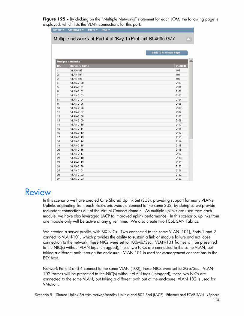
Scenario 5 – Shared Uplink Set with Active/Standby Uplinks and 802.3ad (LACP) - Ethernet and FCoE SAN - vSphere 115
Figure 125 - By clicking on the “Multiple Networks” statement for each LOM, the following page is displayed, which lists the VLAN connections for this port.
Review In this scenario we have created One Shared Uplink Set (SUS), providing support for many VLANs. Uplinks originating from each FlexFabric Module connect to the same SUS, by doing so we provide redundant connections out of the Virtual Connect domain. As multiple uplinks are used from each module, we have also leveraged LACP to improved uplink performance. In this scenario, uplinks from one module only will be active at any given time. We also create two FCoE SAN Fabrics. We created a server profile, with SIX NICs. Two connected to the same VLAN (101), Ports 1 and 2 connect to VLAN-101, which provides the ability to sustain a link or module failure and not loose connection to the network, these NICs were set to 100Mb/Sec. VLAN-101 frames will be presented to the NIC(s) without VLAN tags (untagged), these two NICs are connected to the same VLAN, but taking a different path through the enclosure. VLAN 101 is used for Management connections to the ESX host. Network Ports 3 and 4 connect to the same VLAN (102), these NICs were set to 2Gb/Sec. VLAN-102 frames will be presented to the NIC(s) without VLAN tags (untagged), these two NICs are connected to the same VLAN, but taking a different path out of the enclosure. VLAN 102 is used for VMotion.
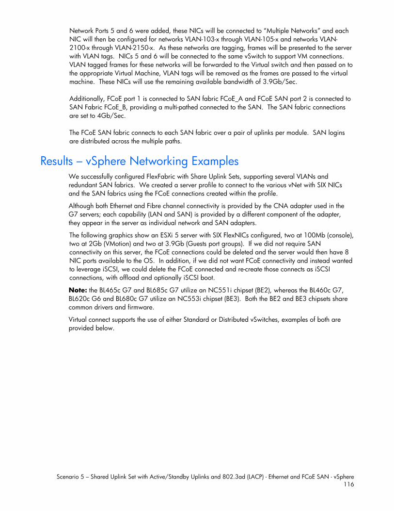
Scenario 5 – Shared Uplink Set with Active/Standby Uplinks and 802.3ad (LACP) - Ethernet and FCoE SAN - vSphere 116
Network Ports 5 and 6 were added, these NICs will be connected to “Multiple Networks” and each NIC will then be configured for networks VLAN-103-x through VLAN-105-x and networks VLAN-2100-x through VLAN-2150-x. As these networks are tagging, frames will be presented to the server with VLAN tags. NICs 5 and 6 will be connected to the same vSwitch to support VM connections. VLAN tagged frames for these networks will be forwarded to the Virtual switch and then passed on to the appropriate Virtual Machine, VLAN tags will be removed as the frames are passed to the virtual machine. These NICs will use the remaining available bandwidth of 3.9Gb/Sec. Additionally, FCoE port 1 is connected to SAN fabric FCoE_A and FCoE SAN port 2 is connected to SAN Fabric FCoE_B, providing a multi-pathed connected to the SAN. The SAN fabric connections are set to 4Gb/Sec. The FCoE SAN fabric connects to each SAN fabric over a pair of uplinks per module. SAN logins are distributed across the multiple paths.
Results – vSphere Networking Examples We successfully configured FlexFabric with Share Uplink Sets, supporting several VLANs and redundant SAN fabrics. We created a server profile to connect to the various vNet with SIX NICs and the SAN fabrics using the FCoE connections created within the profile.
Although both Ethernet and Fibre channel connectivity is provided by the CNA adapter used in the G7 servers; each capability (LAN and SAN) is provided by a different component of the adapter, they appear in the server as individual network and SAN adapters.
The following graphics show an ESXi 5 server with SIX FlexNICs configured, two at 100Mb (console), two at 2Gb (VMotion) and two at 3.9Gb (Guests port groups). If we did not require SAN connectivity on this server, the FCoE connections could be deleted and the server would then have 8 NIC ports available to the OS. In addition, if we did not want FCoE connectivity and instead wanted to leverage iSCSI, we could delete the FCoE connected and re-create those connects as iSCSI connections, with offload and optionally iSCSI boot.
Note: the BL465c G7 and BL685c G7 utilize an NC551i chipset (BE2), whereas the BL460c G7, BL620c G6 and BL680c G7 utilize an NC553i chipset (BE3). Both the BE2 and BE3 chipsets share common drivers and firmware.
Virtual connect supports the use of either Standard or Distributed vSwitches, examples of both are provided below.
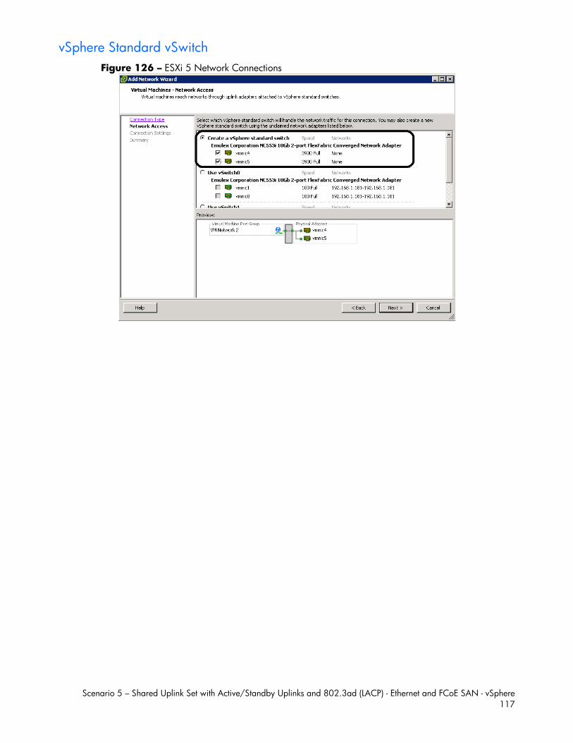
Scenario 5 – Shared Uplink Set with Active/Standby Uplinks and 802.3ad (LACP) - Ethernet and FCoE SAN - vSphere 117
vSphere Standard vSwitch Figure 126 – ESXi 5 Network Connections
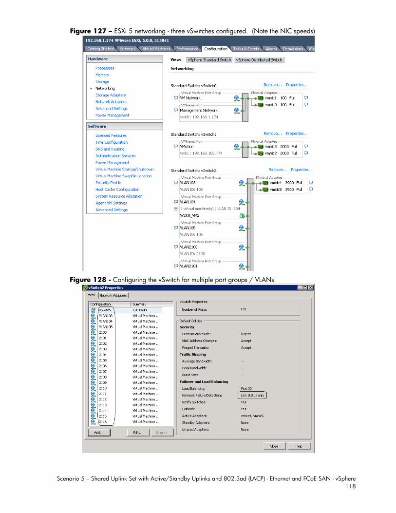
Scenario 5 – Shared Uplink Set with Active/Standby Uplinks and 802.3ad (LACP) - Ethernet and FCoE SAN - vSphere 118
Figure 127 – ESXi 5 networking - three vSwitches configured. (Note the NIC speeds)
Figure 128 - Configuring the vSwitch for multiple port groups / VLANs
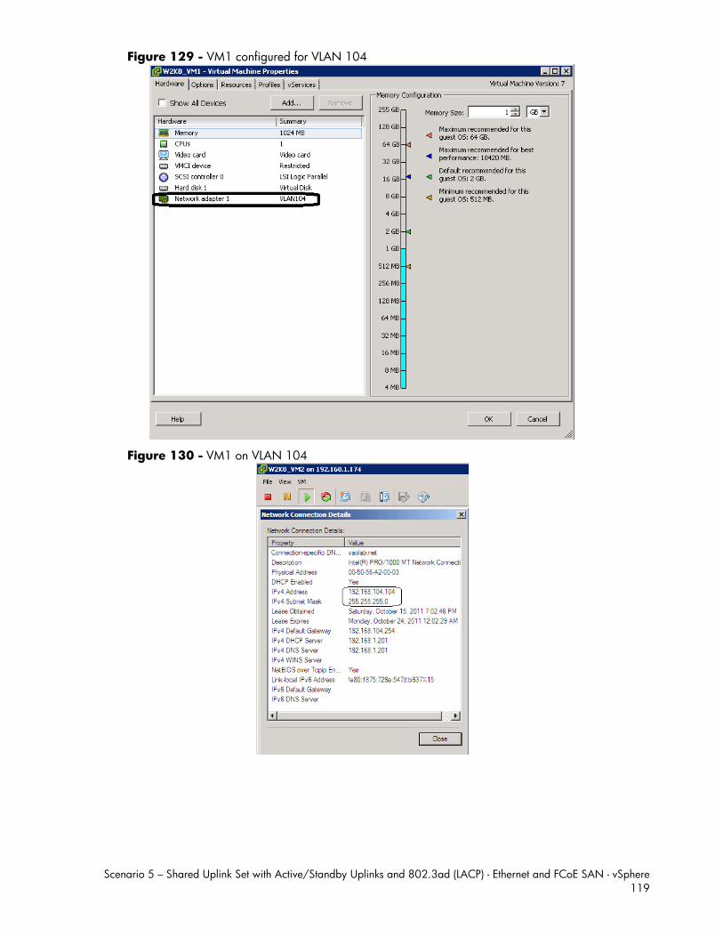
Scenario 5 – Shared Uplink Set with Active/Standby Uplinks and 802.3ad (LACP) - Ethernet and FCoE SAN - vSphere 119
Figure 129 - VM1 configured for VLAN 104
Figure 130 - VM1 on VLAN 104
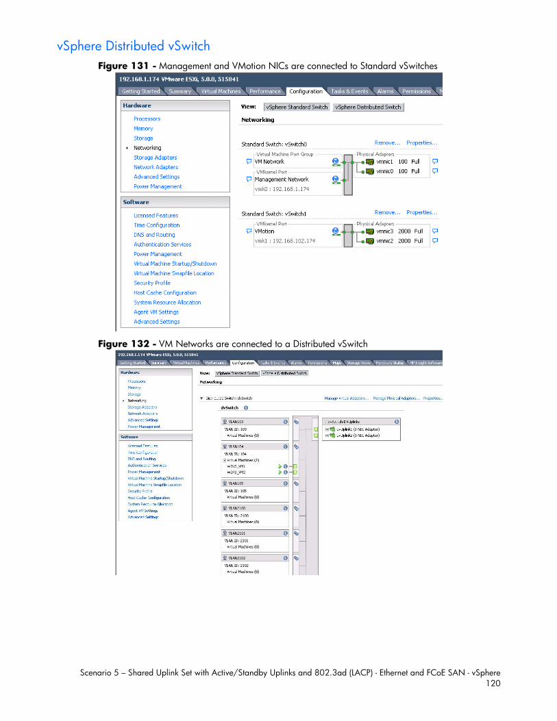
Scenario 5 – Shared Uplink Set with Active/Standby Uplinks and 802.3ad (LACP) - Ethernet and FCoE SAN - vSphere 120
vSphere Distributed vSwitch Figure 131 - Management and VMotion NICs are connected to Standard vSwitches
Figure 132 - VM Networks are connected to a Distributed vSwitch
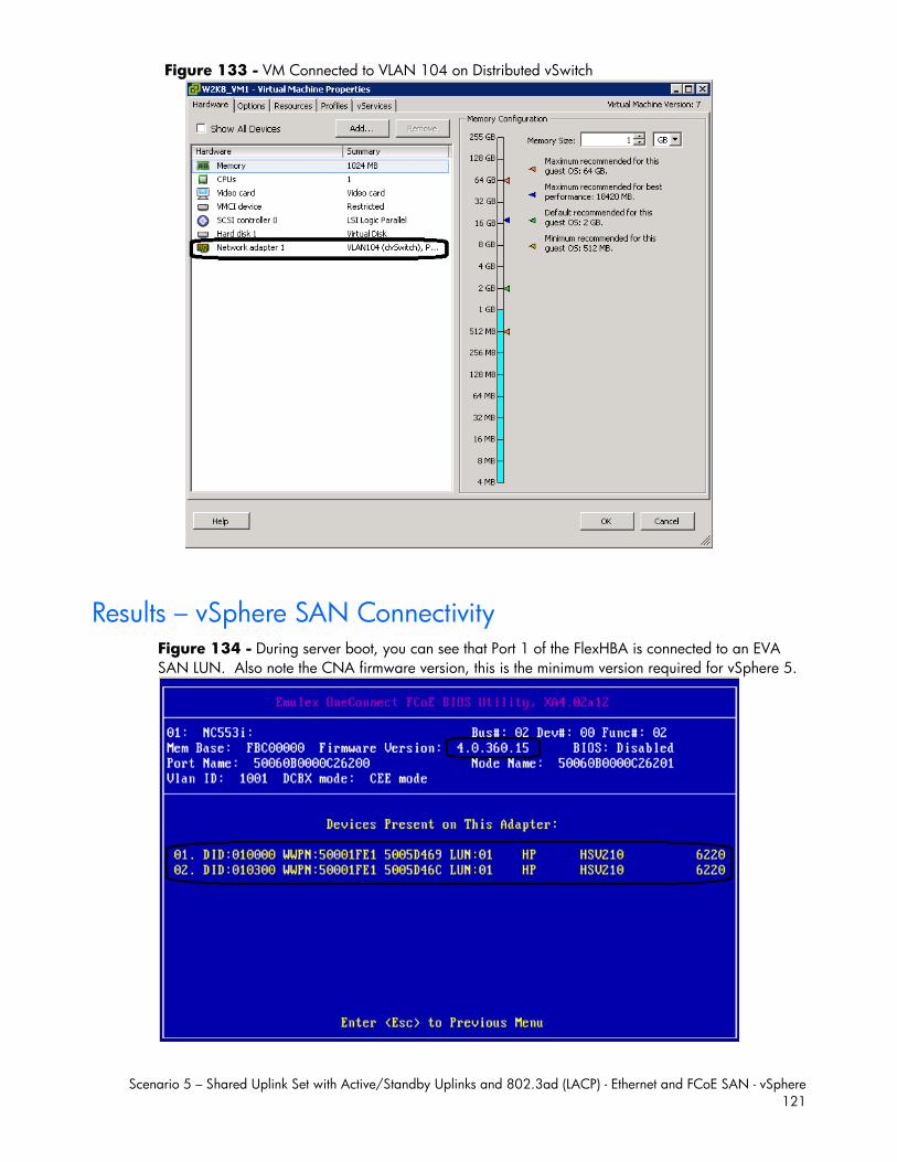
Scenario 5 – Shared Uplink Set with Active/Standby Uplinks and 802.3ad (LACP) - Ethernet and FCoE SAN - vSphere 121
Figure 133 - VM Connected to VLAN 104 on Distributed vSwitch
Results – vSphere SAN Connectivity Figure 134 - During server boot, you can see that Port 1 of the FlexHBA is connected to an EVA SAN LUN. Also note the CNA firmware version, this is the minimum version required for vSphere 5.
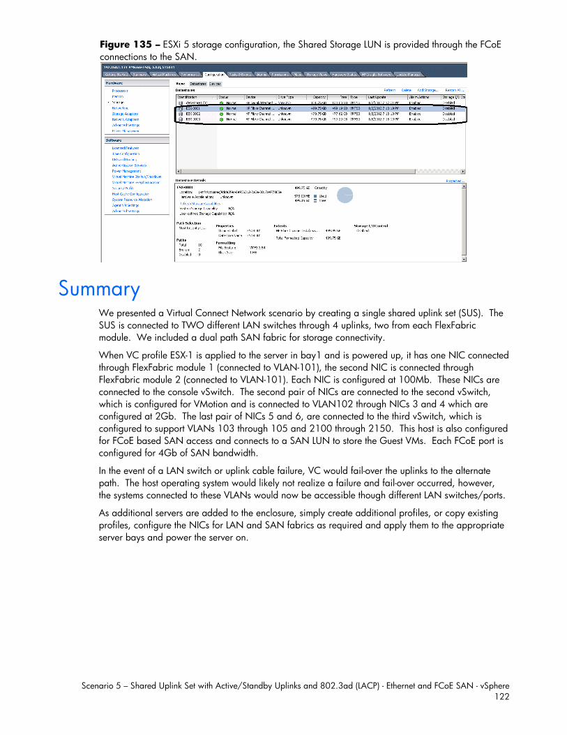
Scenario 5 – Shared Uplink Set with Active/Standby Uplinks and 802.3ad (LACP) - Ethernet and FCoE SAN - vSphere 122
Figure 135 – ESXi 5 storage configuration, the Shared Storage LUN is provided through the FCoE connections to the SAN.
Summary We presented a Virtual Connect Network scenario by creating a single shared uplink set (SUS). The SUS is connected to TWO different LAN switches through 4 uplinks, two from each FlexFabric module. We included a dual path SAN fabric for storage connectivity.
When VC profile ESX-1 is applied to the server in bay1 and is powered up, it has one NIC connected through FlexFabric module 1 (connected to VLAN-101), the second NIC is connected through FlexFabric module 2 (connected to VLAN-101). Each NIC is configured at 100Mb. These NICs are connected to the console vSwitch. The second pair of NICs are connected to the second vSwitch, which is configured for VMotion and is connected to VLAN102 through NICs 3 and 4 which are configured at 2Gb. The last pair of NICs 5 and 6, are connected to the third vSwitch, which is configured to support VLANs 103 through 105 and 2100 through 2150. This host is also configured for FCoE based SAN access and connects to a SAN LUN to store the Guest VMs. Each FCoE port is configured for 4Gb of SAN bandwidth.
In the event of a LAN switch or uplink cable failure, VC would fail-over the uplinks to the alternate path. The host operating system would likely not realize a failure and fail-over occurred, however, the systems connected to these VLANs would now be accessible though different LAN switches/ports.
As additional servers are added to the enclosure, simply create additional profiles, or copy existing profiles, configure the NICs for LAN and SAN fabrics as required and apply them to the appropriate server bays and power the server on.
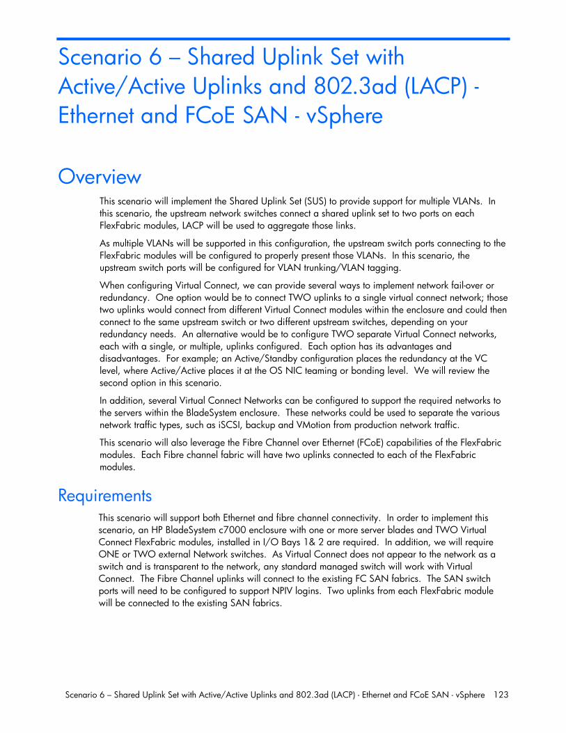
Scenario 6 – Shared Uplink Set with Active/Active Uplinks and 802.3ad (LACP) - Ethernet and FCoE SAN - vSphere 123
Scenario 6 – Shared Uplink Set with Active/Active Uplinks and 802.3ad (LACP) - Ethernet and FCoE SAN - vSphere
Overview This scenario will implement the Shared Uplink Set (SUS) to provide support for multiple VLANs. In this scenario, the upstream network switches connect a shared uplink set to two ports on each FlexFabric modules, LACP will be used to aggregate those links.
As multiple VLANs will be supported in this configuration, the upstream switch ports connecting to the FlexFabric modules will be configured to properly present those VLANs. In this scenario, the upstream switch ports will be configured for VLAN trunking/VLAN tagging.
When configuring Virtual Connect, we can provide several ways to implement network fail-over or redundancy. One option would be to connect TWO uplinks to a single virtual connect network; those two uplinks would connect from different Virtual Connect modules within the enclosure and could then connect to the same upstream switch or two different upstream switches, depending on your redundancy needs. An alternative would be to configure TWO separate Virtual Connect networks, each with a single, or multiple, uplinks configured. Each option has its advantages and disadvantages. For example; an Active/Standby configuration places the redundancy at the VC level, where Active/Active places it at the OS NIC teaming or bonding level. We will review the second option in this scenario.
In addition, several Virtual Connect Networks can be configured to support the required networks to the servers within the BladeSystem enclosure. These networks could be used to separate the various network traffic types, such as iSCSI, backup and VMotion from production network traffic.
This scenario will also leverage the Fibre Channel over Ethernet (FCoE) capabilities of the FlexFabric modules. Each Fibre channel fabric will have two uplinks connected to each of the FlexFabric modules.
Requirements This scenario will support both Ethernet and fibre channel connectivity. In order to implement this scenario, an HP BladeSystem c7000 enclosure with one or more server blades and TWO Virtual Connect FlexFabric modules, installed in I/O Bays 1& 2 are required. In addition, we will require ONE or TWO external Network switches. As Virtual Connect does not appear to the network as a switch and is transparent to the network, any standard managed switch will work with Virtual Connect. The Fibre Channel uplinks will connect to the existing FC SAN fabrics. The SAN switch ports will need to be configured to support NPIV logins. Two uplinks from each FlexFabric module will be connected to the existing SAN fabrics.

Scenario 6 –
Fig1 aPortwithFab
Shared Uplink
ure 136 - Pnd 2 on the fits 1 and 2 onh TWO uplinkbric B.
Set with Active
hysical View; irst network sw the second n
ks per fabric,
e/Active Uplink
Shows two Ewitch and twonetwork switchfrom ports X1
ks and 802.3ad
Ethernet uplinko Ethernet uplih. . The SAN and X2 on m
d (LACP) - Ether
ks from Ports Xinks from Port
N fabrics are amodule 1 to Fa
rnet and FCoE
X5 and X6 onts X5 and X6 also connecteabric A and p
SAN - vSphere
n Module 1 toon Module 2
ed redundantlyports X1 and X
e 124
o Ports to y, X2 to
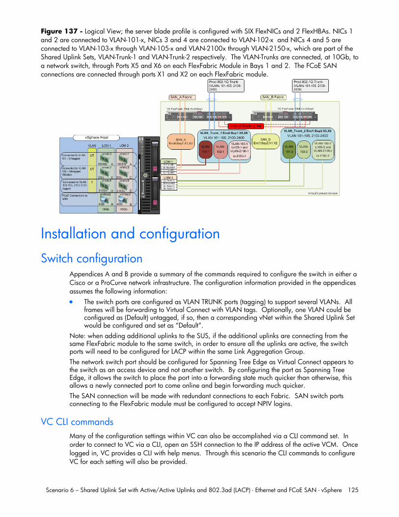
Scenario 6 – Shared Uplink Set with Active/Active Uplinks and 802.3ad (LACP) - Ethernet and FCoE SAN - vSphere 125
Figure 137 - Logical View; the server blade profile is configured with SIX FlexNICs and 2 FlexHBAs. NICs 1 and 2 are connected to VLAN-101-x, NICs 3 and 4 are connected to VLAN-102-x and NICs 4 and 5 are connected to VLAN-103-x through VLAN-105-x and VLAN-2100x through VLAN-2150-x, which are part of the Shared Uplink Sets, VLAN-Trunk-1 and VLAN-Trunk-2 respectively. The VLAN-Trunks are connected, at 10Gb, to a network switch, through Ports X5 and X6 on each FlexFabric Module in Bays 1 and 2. The FCoE SAN connections are connected through ports X1 and X2 on each FlexFabric module.
Installation and configuration
Switch configuration Appendices A and B provide a summary of the commands required to configure the switch in either a Cisco or a ProCurve network infrastructure. The configuration information provided in the appendices assumes the following information: The switch ports are configured as VLAN TRUNK ports (tagging) to support several VLANs. All
frames will be forwarding to Virtual Connect with VLAN tags. Optionally, one VLAN could be configured as (Default) untagged, if so, then a corresponding vNet within the Shared Uplink Set would be configured and set as “Default”.
Note: when adding additional uplinks to the SUS, if the additional uplinks are connecting from the same FlexFabric module to the same switch, in order to ensure all the uplinks are active, the switch ports will need to be configured for LACP within the same Link Aggregation Group. The network switch port should be configured for Spanning Tree Edge as Virtual Connect appears to the switch as an access device and not another switch. By configuring the port as Spanning Tree Edge, it allows the switch to place the port into a forwarding state much quicker than otherwise, this allows a newly connected port to come online and begin forwarding much quicker. The SAN connection will be made with redundant connections to each Fabric. SAN switch ports connecting to the FlexFabric module must be configured to accept NPIV logins.
VC CLI commands Many of the configuration settings within VC can also be accomplished via a CLI command set. In order to connect to VC via a CLI, open an SSH connection to the IP address of the active VCM. Once logged in, VC provides a CLI with help menus. Through this scenario the CLI commands to configure VC for each setting will also be provided.
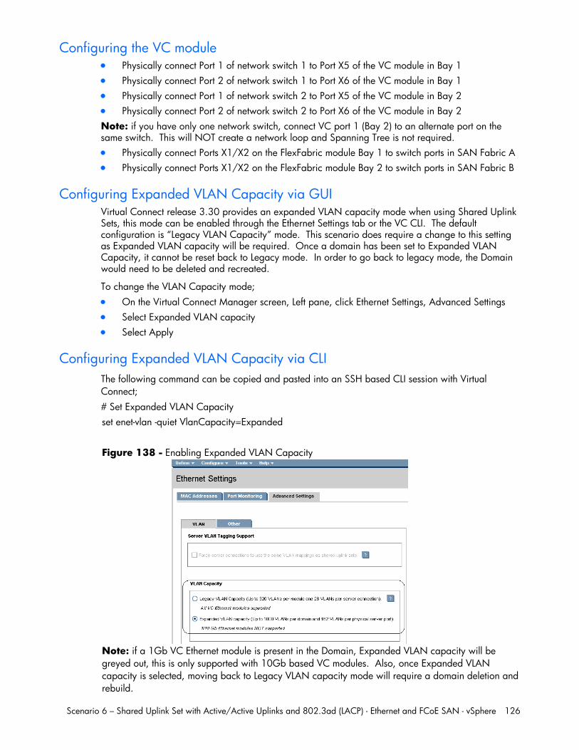
Scenario 6 – Shared Uplink Set with Active/Active Uplinks and 802.3ad (LACP) - Ethernet and FCoE SAN - vSphere 126
Configuring the VC module Physically connect Port 1 of network switch 1 to Port X5 of the VC module in Bay 1 Physically connect Port 2 of network switch 1 to Port X6 of the VC module in Bay 1 Physically connect Port 1 of network switch 2 to Port X5 of the VC module in Bay 2 Physically connect Port 2 of network switch 2 to Port X6 of the VC module in Bay 2 Note: if you have only one network switch, connect VC port 1 (Bay 2) to an alternate port on the same switch. This will NOT create a network loop and Spanning Tree is not required. Physically connect Ports X1/X2 on the FlexFabric module Bay 1 to switch ports in SAN Fabric A Physically connect Ports X1/X2 on the FlexFabric module Bay 2 to switch ports in SAN Fabric B
Configuring Expanded VLAN Capacity via GUI Virtual Connect release 3.30 provides an expanded VLAN capacity mode when using Shared Uplink Sets, this mode can be enabled through the Ethernet Settings tab or the VC CLI. The default configuration is “Legacy VLAN Capacity” mode. This scenario does require a change to this setting as Expanded VLAN capacity will be required. Once a domain has been set to Expanded VLAN Capacity, it cannot be reset back to Legacy mode. In order to go back to legacy mode, the Domain would need to be deleted and recreated.
To change the VLAN Capacity mode; On the Virtual Connect Manager screen, Left pane, click Ethernet Settings, Advanced Settings Select Expanded VLAN capacity Select Apply
Configuring Expanded VLAN Capacity via CLI The following command can be copied and pasted into an SSH based CLI session with Virtual Connect; # Set Expanded VLAN Capacity set enet-vlan -quiet VlanCapacity=Expanded
Figure 138 - Enabling Expanded VLAN Capacity
Note: if a 1Gb VC Ethernet module is present in the Domain, Expanded VLAN capacity will be greyed out, this is only supported with 10Gb based VC modules. Also, once Expanded VLAN capacity is selected, moving back to Legacy VLAN capacity mode will require a domain deletion and rebuild.
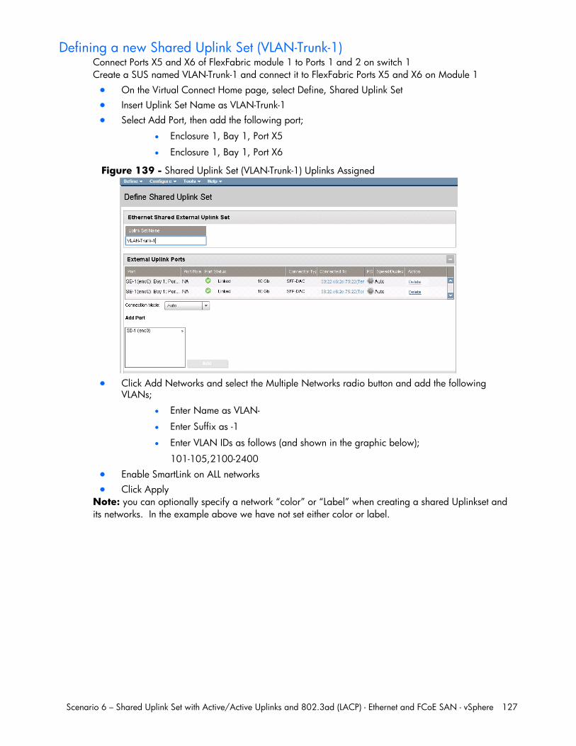
Scenario 6 – Shared Uplink Set with Active/Active Uplinks and 802.3ad (LACP) - Ethernet and FCoE SAN - vSphere 127
Defining a new Shared Uplink Set (VLAN-Trunk-1) Connect Ports X5 and X6 of FlexFabric module 1 to Ports 1 and 2 on switch 1 Create a SUS named VLAN-Trunk-1 and connect it to FlexFabric Ports X5 and X6 on Module 1 On the Virtual Connect Home page, select Define, Shared Uplink Set Insert Uplink Set Name as VLAN-Trunk-1 Select Add Port, then add the following port;
Enclosure 1, Bay 1, Port X5
Enclosure 1, Bay 1, Port X6
Figure 139 - Shared Uplink Set (VLAN-Trunk-1) Uplinks Assigned
Click Add Networks and select the Multiple Networks radio button and add the following
VLANs;
Enter Name as VLAN-
Enter Suffix as -1
Enter VLAN IDs as follows (and shown in the graphic below);
101-105,2100-2400 Enable SmartLink on ALL networks Click Apply
Note: you can optionally specify a network “color” or “Label” when creating a shared Uplinkset and its networks. In the example above we have not set either color or label.
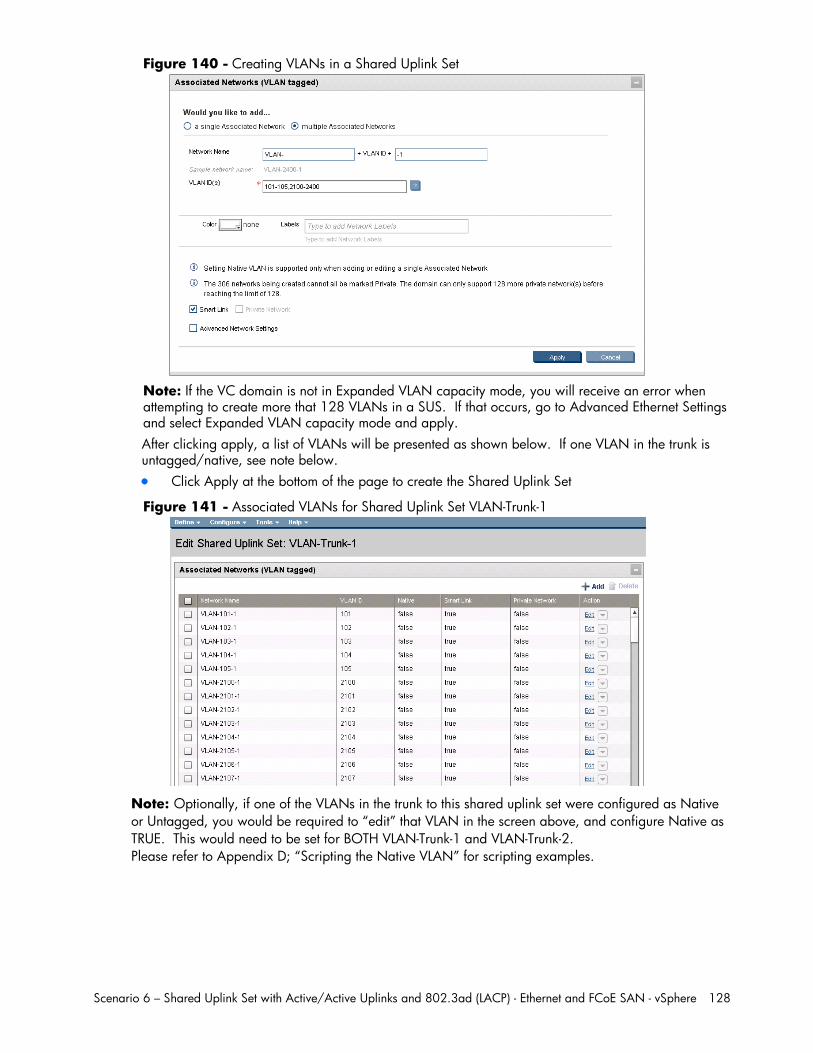
Scenario 6 – Shared Uplink Set with Active/Active Uplinks and 802.3ad (LACP) - Ethernet and FCoE SAN - vSphere 128
Figure 140 - Creating VLANs in a Shared Uplink Set
Note: If the VC domain is not in Expanded VLAN capacity mode, you will receive an error when attempting to create more that 128 VLANs in a SUS. If that occurs, go to Advanced Ethernet Settings and select Expanded VLAN capacity mode and apply. After clicking apply, a list of VLANs will be presented as shown below. If one VLAN in the trunk is untagged/native, see note below. Click Apply at the bottom of the page to create the Shared Uplink Set
Figure 141 - Associated VLANs for Shared Uplink Set VLAN-Trunk-1
Note: Optionally, if one of the VLANs in the trunk to this shared uplink set were configured as Native or Untagged, you would be required to “edit” that VLAN in the screen above, and configure Native as TRUE. This would need to be set for BOTH VLAN-Trunk-1 and VLAN-Trunk-2. Please refer to Appendix D; “Scripting the Native VLAN” for scripting examples.
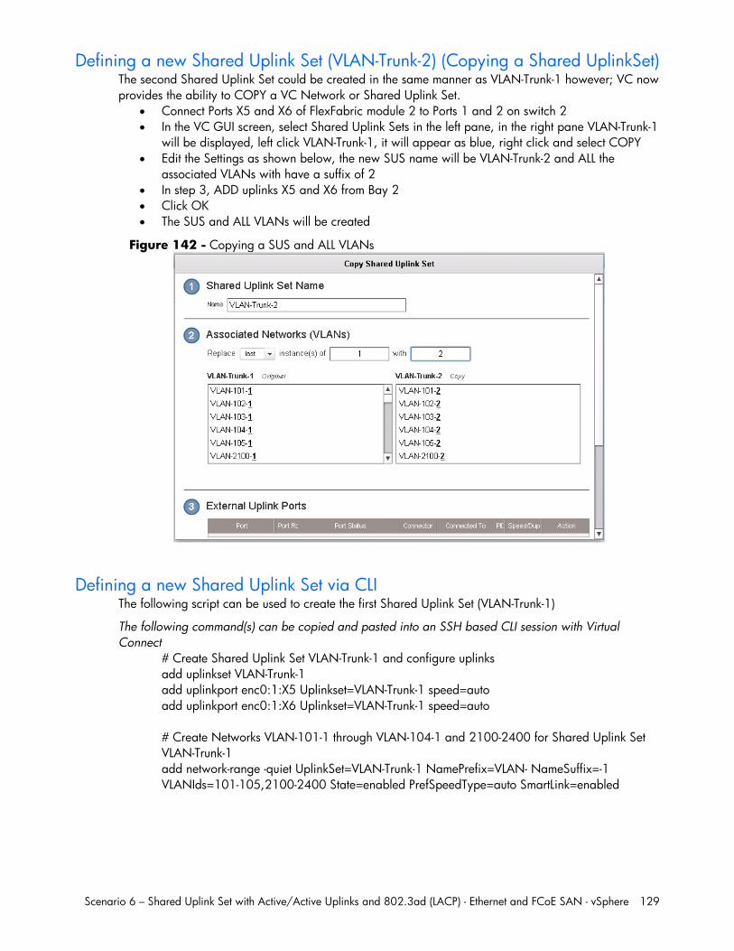
Scenario 6 – Shared Uplink Set with Active/Active Uplinks and 802.3ad (LACP) - Ethernet and FCoE SAN - vSphere 129
Defining a new Shared Uplink Set (VLAN-Trunk-2) (Copying a Shared UplinkSet) The second Shared Uplink Set could be created in the same manner as VLAN-Trunk-1 however; VC now provides the ability to COPY a VC Network or Shared Uplink Set.
Connect Ports X5 and X6 of FlexFabric module 2 to Ports 1 and 2 on switch 2 In the VC GUI screen, select Shared Uplink Sets in the left pane, in the right pane VLAN-Trunk-1
will be displayed, left click VLAN-Trunk-1, it will appear as blue, right click and select COPY Edit the Settings as shown below, the new SUS name will be VLAN-Trunk-2 and ALL the
associated VLANs with have a suffix of 2 In step 3, ADD uplinks X5 and X6 from Bay 2 Click OK The SUS and ALL VLANs will be created
Figure 142 - Copying a SUS and ALL VLANs
Defining a new Shared Uplink Set via CLI The following script can be used to create the first Shared Uplink Set (VLAN-Trunk-1)
The following command(s) can be copied and pasted into an SSH based CLI session with Virtual Connect
# Create Shared Uplink Set VLAN-Trunk-1 and configure uplinks add uplinkset VLAN-Trunk-1 add uplinkport enc0:1:X5 Uplinkset=VLAN-Trunk-1 speed=auto add uplinkport enc0:1:X6 Uplinkset=VLAN-Trunk-1 speed=auto # Create Networks VLAN-101-1 through VLAN-104-1 and 2100-2400 for Shared Uplink Set VLAN-Trunk-1 add network-range -quiet UplinkSet=VLAN-Trunk-1 NamePrefix=VLAN- NameSuffix=-1 VLANIds=101-105,2100-2400 State=enabled PrefSpeedType=auto SmartLink=enabled
Scenario 6 – Shared Uplink Set with Active/Active Uplinks and 802.3ad (LACP) - Ethernet and FCoE SAN - vSphere 130
The following script can be used to create the Second Shared Uplink Set (VLAN-Trunk-2) # Create Shared Uplink Set VLAN-Trunk-2 and configure uplinks add uplinkset VLAN-Trunk-2 add uplinkport enc0:2:X5 Uplinkset=VLAN-Trunk-2 speed=auto add uplinkport enc0:2:X6 Uplinkset=VLAN-Trunk-2 speed=auto # Create Networks VLAN101-2 through VLAN105-2 and VLAN-2100-2 through VLAN-2400-2 for Shared Uplink Set VLAN-Trunk-2 add network-range -quiet UplinkSet=VLAN-Trunk-2 NamePrefix=VLAN- NameSuffix=-2 VLANIds=101-105,2100-2400 State=enabled PrefSpeedType=auto SmartLink=enabled
Summary Note: In this scenario we have created two independent Share Uplink Sets (SUS), each originating from the opposite FlexFabric Modules, by doing so we provide the ability to create separate and redundant connections out of the Virtual Connect domain. When we create the server profiles, you will see how the NICs will connect to VLANs accessed through the opposite VC module, which provides the ability to create an Active / Active uplink scenario. Alternatively, we could have created a single SUS and assigned both sets of these uplink ports to the same SUS, however, this would have provided an Active/Standby uplink scenario, as shown in Scenario 5.
Defining a new (FCoE) SAN Fabric via GUI Create a Fabric and name it “FCoE_A” On the Virtual Connect Manager screen, click Define, SAN Fabric to create the first Fabric Enter the Network Name of “FCoE_A” Select Add Port, then add the following ports;
Enclosure 1, Bay 1, Port X1 Enclosure 1, Bay 1, Port X2
Select the Advanced Settings Select Automatic Login Re-Distribution
Select Apply
Create a second Fabric and name it “FCoE_B” On the Virtual Connect Manager screen, click Define, SAN Fabric to create the second Fabric Enter the Network Name of “FCoE_B” Select Add Port, then add the following ports;
Enclosure 1, Bay 2, Port X1 Enclosure 1, Bay 2, Port X2
Select the Advanced Settings Select Automatic Login Re-Distribution
Select Apply
Defining SAN Fabrics via CLI The following command(s) can be copied and pasted into an SSH based CLI session with Virtual Connect #Create the SAN Fabrics FCoE_A and FCoE_B and configure uplinks as discussed above Add fabric FCoE_A Bay=1 Ports=1,2 LinkDist=Auto Add fabric FCoE_B Bay=2 Ports=1,2 LinkDist=Auto
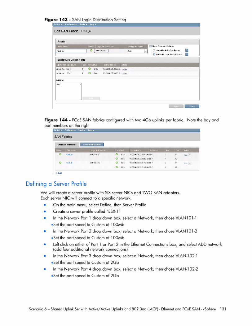
Scenario 6 – Shared Uplink Set with Active/Active Uplinks and 802.3ad (LACP) - Ethernet and FCoE SAN - vSphere 131
Figure 143 - SAN Login Distribution Setting
Figure 144 - FCoE SAN fabrics configured with two 4Gb uplinks per fabric. Note the bay and port numbers on the right
Defining a Server Profile We will create a server profile with SIX server NICs and TWO SAN adapters. Each server NIC will connect to a specific network. On the main menu, select Define, then Server Profile Create a server profile called “ESX-1” In the Network Port 1 drop down box, select a Network, then chose VLAN101-1
Set the port speed to Custom at 100Mb In the Network Port 2 drop down box, select a Network, then chose VLAN101-2
Set the port speed to Custom at 100Mb Left click on either of Port 1 or Port 2 in the Ethernet Connections box, and select ADD network
(add four additional network connections) In the Network Port 3 drop down box, select a Network, then chose VLAN-102-1
Set the port speed to Custom at 2Gb In the Network Port 4 drop down box, select a Network, then chose VLAN-102-2
Set the port speed to Custom at 2Gb
Scenario 6 – Shared Uplink Set with Active/Active Uplinks and 802.3ad (LACP) - Ethernet and FCoE SAN - vSphere 132
In the Network Port 5 drop down box, select Multiple Networks Configure for networks VLAN-103-1 through VLAN-105-1 and VLAN-2100-1 through VLAN-
2150-1 Leave the network speed as Auto
In the Network Port 6 drop down box, select Multiple Networks Configure for networks VLAN-103-2 through VLAN-105-2 and VLAN-2100-2 through VLAN-
2150-2 Leave the network speed as Auto
Expand the FCoE Connections box, for Bay 1, select FCoE_A for Bay 2, select FCoE_B Do not configure FC SAN or iSCSI Connection In the Assign Profile to Server Bay box, locate the Select Location drop down and select Bay 1,
they apply Prior to applying the profile, ensure that the server in Bay 1 is currently OFF
Note: you should now have a server profile assigned to Bay 1, with 4 Server NIC connections. NICs 1&2 should be connected to networks VLAN-101-x (MGMT), NICs 3&4 should be connected VLAN-102-x (VMotion) to networks VLAN103-x through VLAN105-x and VLAN-2100-x through VLAN-2150-x. FCoE SAN fabrics are connected to, Port 1 - FCoE_A and Port 2 - FCoE_B.
Defining a Server Profile via CLI The following command(s) can be copied and pasted into an SSH based CLI session with Virtual Connect # Create Server Profile ESX-1 add profile ESX-1 -nodefaultfcconn -nodefaultfcoeconn set enet-connection ESX-1 1 pxe=Enabled Network=VLAN-101-1 SpeedType=Custom Speed=100 set enet-connection ESX-1 2 pxe=Disabled Network=VLAN-101-2 SpeedType=Custom Speed=100 add enet-connection ESX-1 pxe=Disabled Network=VLAN-102-1 SpeedType=Custom Speed=2000 add enet-connection ESX-1 pxe=Disabled Network=VLAN-102-2 SpeedType=Custom Speed=2000 add enet-connection ESX-1 pxe=Disabled add server-port-map-range ESX-1:5 UplinkSet=VLAN-Trunk-1 VLanIds=103-105,2100-2150 add enet-connection ESX-1 pxe=Disabled add server-port-map-range ESX-1:6 UplinkSet=VLAN-Trunk-2 VLanIds=103-105,2100-2150 add fcoe-connection ESX-1 Fabric=FCoE_A SpeedType=4Gb add fcoe-connection ESX-1 Fabric=FCoE_B SpeedType=4Gb poweroff server 1 assign profile ESX-1 enc0:1
Note: the “add server-port-map-range” command is new to VC firmware release 3.30 and can be used to map many VLANs to a server NIC, in a single command. Prior releases would have required one command to create the NIC and one additional command per VLAN mapping added. This command will make profile scripting much easier, less complicated and quicker.
Note: The speed of the NIC and SAN connections, as well as the MAC and WWN. Also, note that the FCoE connections are assigned to the two SAN fabrics created earlier and use ports LOM:1-b and LOM:2-b.
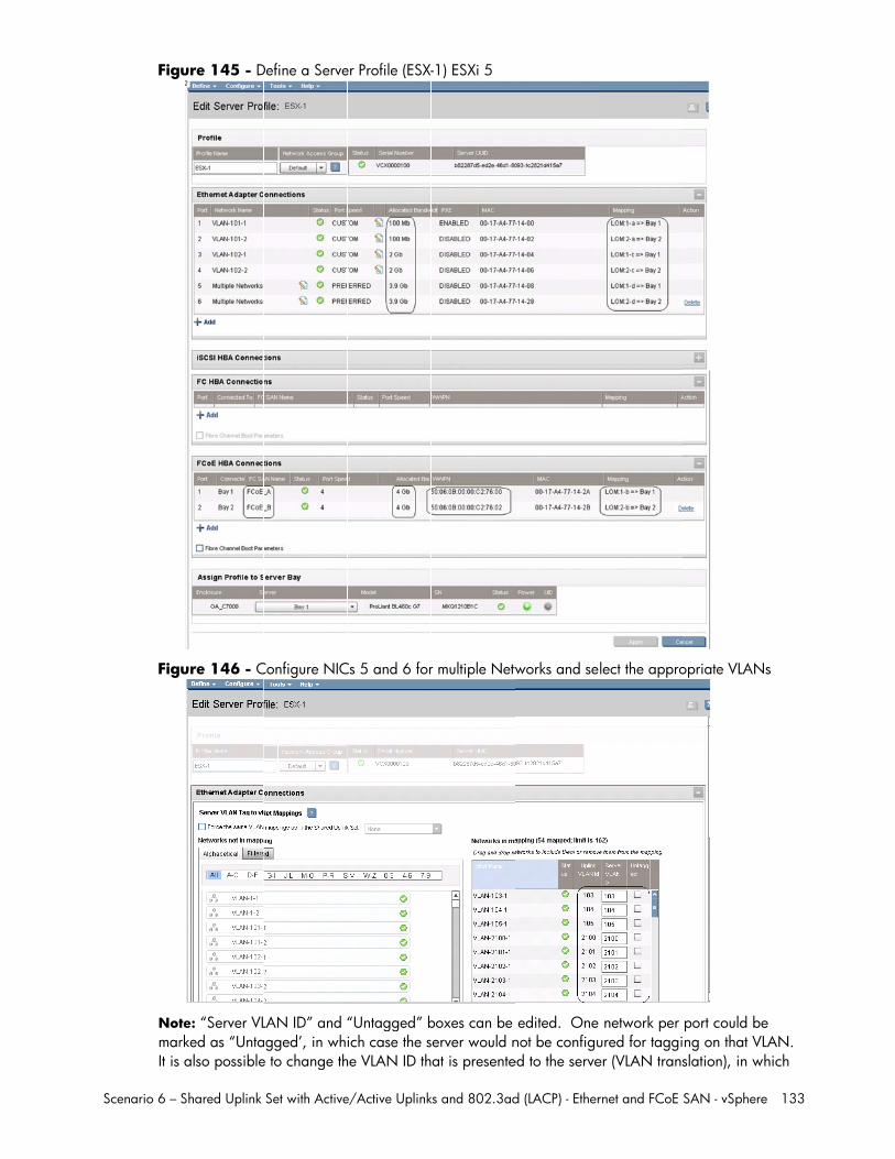
Scenario 6 –
Fig
Fig
NotmarIt is
Shared Uplink
ure 145 - D
ure 146 - C
te: “Server VLrked as “Unta also possible
Set with Active
Define a Serve
Configure NIC
LAN ID” and “agged’, in whe to change th
e/Active Uplink
er Profile (ESX-
Cs 5 and 6 for
“Untagged” bich case the s
he VLAN ID th
ks and 802.3ad
-1) ESXi 5
r multiple Netw
boxes can be server would nat is presente
d (LACP) - Ether
works and se
edited. Onenot be configued to the serve
rnet and FCoE
lect the appro
network per ured for taggier (VLAN trans
SAN - vSphere
opriate VLANs
port could being on that VLslation), in wh
e 133
s
e LAN. hich
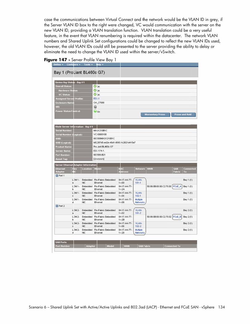
Scenario 6 –
casthe newfeatnumhowelim
Fig
Shared Uplink
e the commun Server VLAN w VLAN ID, prture, in the ev
mbers and Shawever, the oldminate the nee
ure 147 - S
Set with Active
nications betw ID box to theroviding a VLAvent that VLANared Uplink S VLAN IDs co
ed to change t
erver Profile V
e/Active Uplink
ween Virtual Ce right were chAN translatio
N renumberinget configuratio
ould still be prthe VLAN ID u
View Bay 1
ks and 802.3ad
Connect and thhanged, VC wn function. Vg is required wons could be esented to theused within th
d (LACP) - Ether
he network wwould commu
VLAN translatiowithin the dat changed to ree server provihe server/vSw
rnet and FCoE
would be the Vnication with on could be atacenter. Theeflect the newding the abili
witch.
SAN - vSphere
VLAN ID in gre the server ona very useful network VLA
w VLAN IDs usty to delay or
e 134
ey, if the
AN sed, r
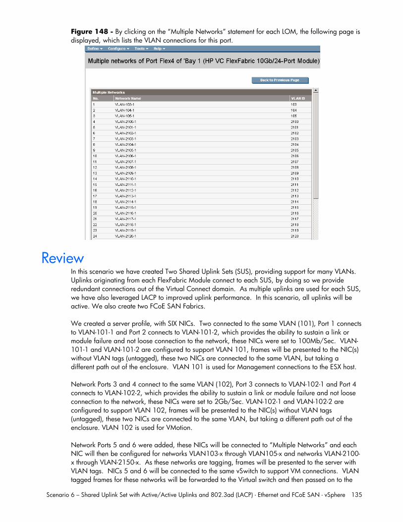
Scenario 6 – Shared Uplink Set with Active/Active Uplinks and 802.3ad (LACP) - Ethernet and FCoE SAN - vSphere 135
Figure 148 - By clicking on the “Multiple Networks” statement for each LOM, the following page is displayed, which lists the VLAN connections for this port.
Review In this scenario we have created Two Shared Uplink Sets (SUS), providing support for many VLANs. Uplinks originating from each FlexFabric Module connect to each SUS, by doing so we provide redundant connections out of the Virtual Connect domain. As multiple uplinks are used for each SUS, we have also leveraged LACP to improved uplink performance. In this scenario, all uplinks will be active. We also create two FCoE SAN Fabrics. We created a server profile, with SIX NICs. Two connected to the same VLAN (101), Port 1 connects to VLAN-101-1 and Port 2 connects to VLAN-101-2, which provides the ability to sustain a link or module failure and not loose connection to the network, these NICs were set to 100Mb/Sec. VLAN-101-1 and VLAN-101-2 are configured to support VLAN 101, frames will be presented to the NIC(s) without VLAN tags (untagged), these two NICs are connected to the same VLAN, but taking a different path out of the enclosure. VLAN 101 is used for Management connections to the ESX host. Network Ports 3 and 4 connect to the same VLAN (102), Port 3 connects to VLAN-102-1 and Port 4 connects to VLAN-102-2, which provides the ability to sustain a link or module failure and not loose connection to the network, these NICs were set to 2Gb/Sec. VLAN-102-1 and VLAN-102-2 are configured to support VLAN 102, frames will be presented to the NIC(s) without VLAN tags (untagged), these two NICs are connected to the same VLAN, but taking a different path out of the enclosure. VLAN 102 is used for VMotion. Network Ports 5 and 6 were added, these NICs will be connected to “Multiple Networks” and each NIC will then be configured for networks VLAN103-x through VLAN105-x and networks VLAN-2100-x through VLAN-2150-x. As these networks are tagging, frames will be presented to the server with VLAN tags. NICs 5 and 6 will be connected to the same vSwitch to support VM connections. VLAN tagged frames for these networks will be forwarded to the Virtual switch and then passed on to the
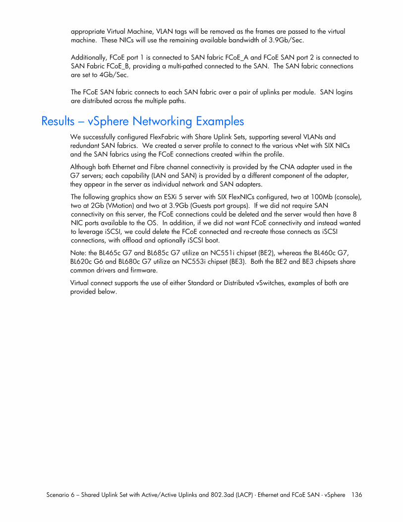
Scenario 6 – Shared Uplink Set with Active/Active Uplinks and 802.3ad (LACP) - Ethernet and FCoE SAN - vSphere 136
appropriate Virtual Machine, VLAN tags will be removed as the frames are passed to the virtual machine. These NICs will use the remaining available bandwidth of 3.9Gb/Sec. Additionally, FCoE port 1 is connected to SAN fabric FCoE_A and FCoE SAN port 2 is connected to SAN Fabric FCoE_B, providing a multi-pathed connected to the SAN. The SAN fabric connections are set to 4Gb/Sec. The FCoE SAN fabric connects to each SAN fabric over a pair of uplinks per module. SAN logins are distributed across the multiple paths.
Results – vSphere Networking Examples We successfully configured FlexFabric with Share Uplink Sets, supporting several VLANs and redundant SAN fabrics. We created a server profile to connect to the various vNet with SIX NICs and the SAN fabrics using the FCoE connections created within the profile.
Although both Ethernet and Fibre channel connectivity is provided by the CNA adapter used in the G7 servers; each capability (LAN and SAN) is provided by a different component of the adapter, they appear in the server as individual network and SAN adapters.
The following graphics show an ESXi 5 server with SIX FlexNICs configured, two at 100Mb (console), two at 2Gb (VMotion) and two at 3.9Gb (Guests port groups). If we did not require SAN connectivity on this server, the FCoE connections could be deleted and the server would then have 8 NIC ports available to the OS. In addition, if we did not want FCoE connectivity and instead wanted to leverage iSCSI, we could delete the FCoE connected and re-create those connects as iSCSI connections, with offload and optionally iSCSI boot.
Note: the BL465c G7 and BL685c G7 utilize an NC551i chipset (BE2), whereas the BL460c G7, BL620c G6 and BL680c G7 utilize an NC553i chipset (BE3). Both the BE2 and BE3 chipsets share common drivers and firmware.
Virtual connect supports the use of either Standard or Distributed vSwitches, examples of both are provided below.
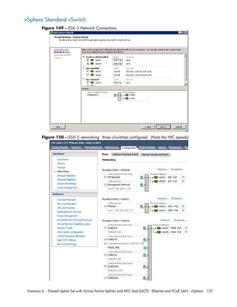
Scenario 6 – Shared Uplink Set with Active/Active Uplinks and 802.3ad (LACP) - Ethernet and FCoE SAN - vSphere 137
vSphere Standard vSwitch Figure 149 – ESXi 5 Network Connections
Figure 150 – ESXi 5 networking - three vSwitches configured. (Note the NIC speeds)
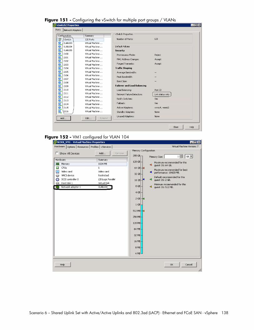
Scenario 6 – Shared Uplink Set with Active/Active Uplinks and 802.3ad (LACP) - Ethernet and FCoE SAN - vSphere 138
Figure 151 - Configuring the vSwitch for multiple port groups / VLANs
Figure 152 - VM1 configured for VLAN 104
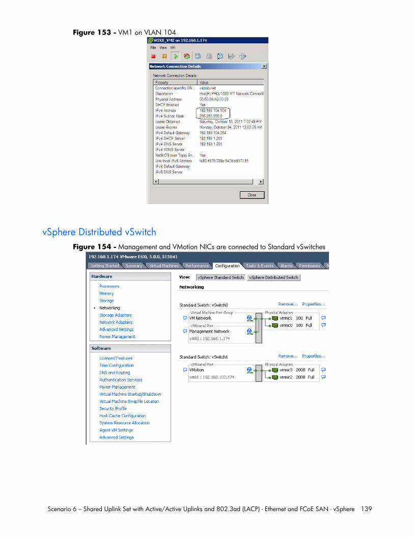
Scenario 6 – Shared Uplink Set with Active/Active Uplinks and 802.3ad (LACP) - Ethernet and FCoE SAN - vSphere 139
Figure 153 - VM1 on VLAN 104
vSphere Distributed vSwitch Figure 154 - Management and VMotion NICs are connected to Standard vSwitches
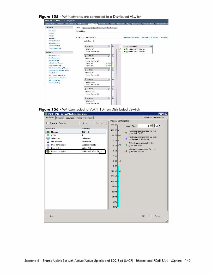
Scenario 6 – Shared Uplink Set with Active/Active Uplinks and 802.3ad (LACP) - Ethernet and FCoE SAN - vSphere 140
Figure 155 - VM Networks are connected to a Distributed vSwitch
Figure 156 - VM Connected to VLAN 104 on Distributed vSwitch
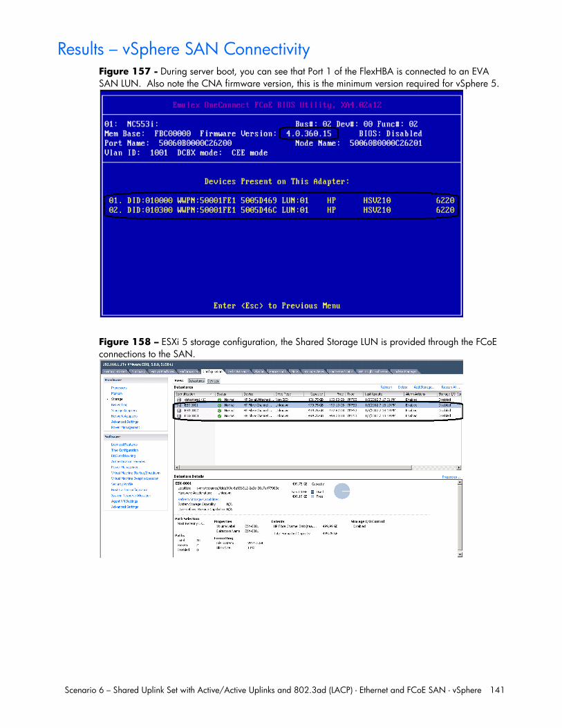
Scenario 6 – Shared Uplink Set with Active/Active Uplinks and 802.3ad (LACP) - Ethernet and FCoE SAN - vSphere 141
Results – vSphere SAN Connectivity Figure 157 - During server boot, you can see that Port 1 of the FlexHBA is connected to an EVA SAN LUN. Also note the CNA firmware version, this is the minimum version required for vSphere 5.
Figure 158 – ESXi 5 storage configuration, the Shared Storage LUN is provided through the FCoE connections to the SAN.
Scenario 6 – Shared Uplink Set with Active/Active Uplinks and 802.3ad (LACP) - Ethernet and FCoE SAN - vSphere 142
Summary We presented a Virtual Connect Network scenario by creating two shared uplink sets (SUS), each SUS is connected with TWO active uplinks; both SUS’ can actively pass traffic. We included a dual path SAN fabric for storage connectivity.
When VC profile ESX-1 is applied to the server in bay1 and is powered up, it has one NIC connected through FlexFabric module 1 (connected to VLAN-101-1), the second NIC is connected through FlexFabric module 2 (connected to VLAN-101-2). Each NIC is configured at 100Mb. These NICs are connected to the console vSwitch. The second pair of NICs are connected to the second vSwitch, which is configured for VMotion and is connected to VLAN102-x through NICs 3 and 4 which are configured at 2Gb. The last pair of NICs 5 and 6, are connected to the third vSwitch, which is configured to support VLANs 103 through 105 and 2100 through 2150. This host is also configured for FCoE based SAN access and connects to a SAN LUN to store the Guest VMs. Each FCoE port is configured for 4Gb of SAN bandwidth.
As additional servers are added to the enclosure, simply create additional profiles, or copy existing profiles, configure the NICs for LAN and SAN fabrics as required and apply them to the appropriate server bays and power the server on.
Scenario 7 – Tunneled VLANs and Shared Uplink Set with Active/Active Uplinks and 802.3ad (LACP) - Ethernet and FCoE SAN - vSphere 143
Scenario 7 – Tunneled VLANs and Shared Uplink Set with Active/Active Uplinks and 802.3ad (LACP) - Ethernet and FCoE SAN - vSphere
Overview This scenario will implement the VLAN-Tunnel to provide support for multiple VLANs. In this scenario, the upstream network switches connect a VLAN-Tunnel to two ports on each FlexFabric modules, LACP will be used to aggregate those links. A Shared Uplink Set will also be used to provide connectivity for the Management and VMotion networks only.
As multiple VLANs will be supported in this configuration, the upstream switch ports connecting to the FlexFabric modules will be configured to properly present those VLANs. In this scenario, the upstream switch ports will be configured for VLAN trunking/VLAN tagging.
When configuring Virtual Connect, we can provide several ways to implement network fail-over or redundancy. One option would be to connect TWO uplinks to a single virtual connect network; those two uplinks would connect from different Virtual Connect modules within the enclosure and could then connect to the same upstream switch or two different upstream switches, depending on your redundancy needs. An alternative would be to configure TWO separate Virtual Connect networks, each with a single, or multiple, uplinks configured. Each option has its advantages and disadvantages. For example; an Active/Standby configuration places the redundancy at the VC level, where Active/Active places it at the OS NIC teaming or bonding level. We will review the first option in this scenario. We will review the second option in this scenario.
In addition, several Virtual Connect Networks can be configured to support the required networks to the servers within the BladeSystem enclosure. These networks could be used to separate the various network traffic types, such as iSCSI, backup and VMotion from production network traffic.
This scenario will also leverage the Fibre Channel over Ethernet (FCoE) capabilities of the FlexFabric modules. Each Fibre channel fabric will have two uplinks connected to each of the FlexFabric modules.
Requirements This scenario will support both Ethernet and fibre channel connectivity. In order to implement this scenario, an HP BladeSystem c7000 enclosure with one or more server blades and TWO Virtual Connect FlexFabric modules, installed in I/O Bays 1& 2 are required. In addition, we will require ONE or TWO external Network switches. As Virtual Connect does not appear to the network as a switch and is transparent to the network, any standard managed switch will work with Virtual Connect. The Fibre Channel uplinks will connect to the existing FC SAN fabrics. The SAN switch ports will need to be configured to support NPIV logins. Two uplinks from each FlexFabric module will be connected to the existing SAN fabrics.
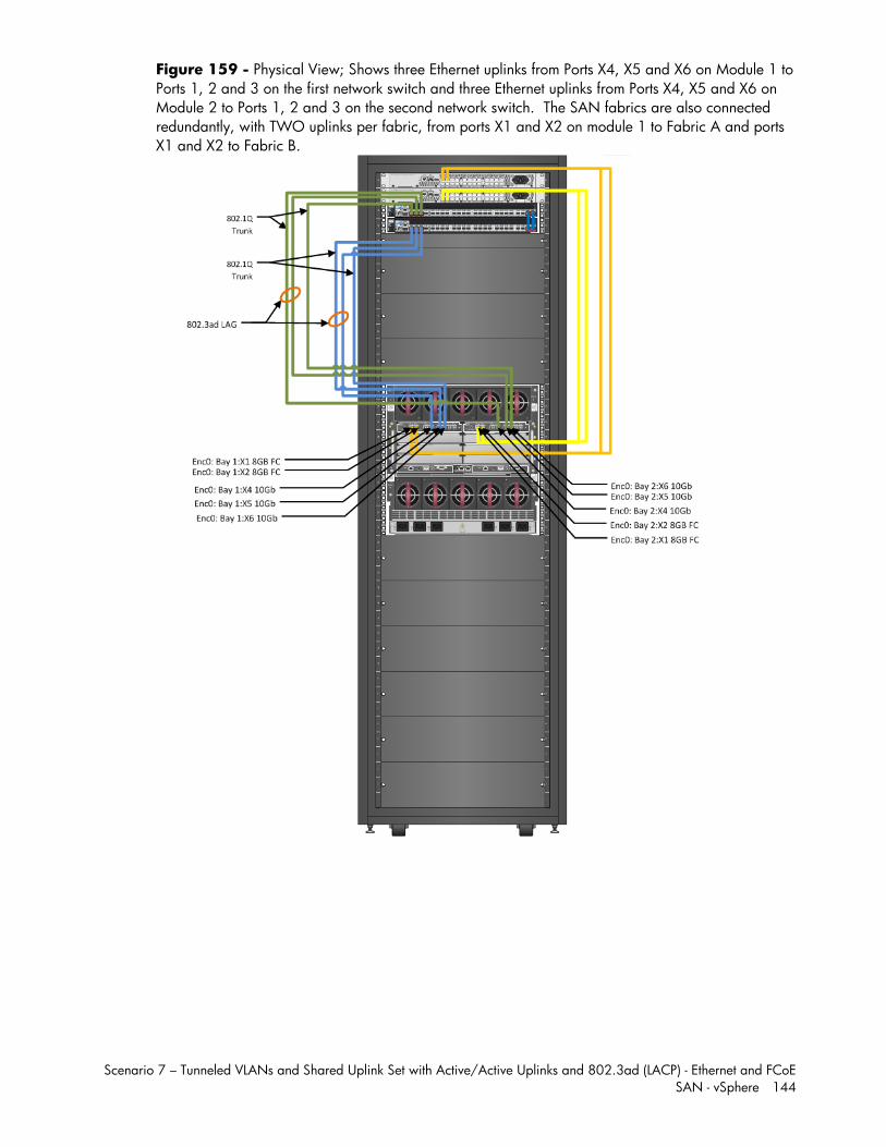
Scenario 7 – Tunneled VLANs and Shared Uplink Set with Active/Active Uplinks and 802.3ad (LACP) - Ethernet and FCoE SAN - vSphere 144
Figure 159 - Physical View; Shows three Ethernet uplinks from Ports X4, X5 and X6 on Module 1 to Ports 1, 2 and 3 on the first network switch and three Ethernet uplinks from Ports X4, X5 and X6 on Module 2 to Ports 1, 2 and 3 on the second network switch. The SAN fabrics are also connected redundantly, with TWO uplinks per fabric, from ports X1 and X2 on module 1 to Fabric A and ports X1 and X2 to Fabric B.
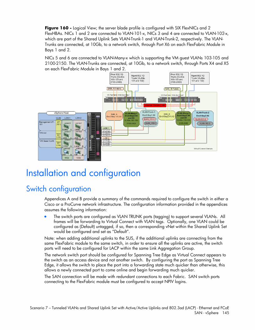
Scenario 7 – Tunneled VLANs and Shared Uplink Set with Active/Active Uplinks and 802.3ad (LACP) - Ethernet and FCoE SAN - vSphere 145
Figure 160 - Logical View; the server blade profile is configured with SIX FlexNICs and 2 FlexHBAs. NICs 1 and 2 are connected to VLAN-101-x, NICs 3 and 4 are connected to VLAN-102-x, which are part of the Shared Uplink Sets VLAN-Trunk-1 and VLAN-Trunk-2, respectively. The VLAN-Trunks are connected, at 10Gb, to a network switch, through Port X6 on each FlexFabric Module in Bays 1 and 2.
NICs 5 and 6 are connected to VLAN-Many-x which is supporting the VM guest VLANs 103-105 and 2100-2150. The VLAN-Trunks are connected, at 10Gb, to a network switch, through Ports X4 and X5 on each FlexFabric Module in Bays 1 and 2.
Installation and configuration
Switch configuration Appendices A and B provide a summary of the commands required to configure the switch in either a Cisco or a ProCurve network infrastructure. The configuration information provided in the appendices assumes the following information: The switch ports are configured as VLAN TRUNK ports (tagging) to support several VLANs. All
frames will be forwarding to Virtual Connect with VLAN tags. Optionally, one VLAN could be configured as (Default) untagged, if so, then a corresponding vNet within the Shared Uplink Set would be configured and set as “Default”.
Note: when adding additional uplinks to the SUS, if the additional uplinks are connecting from the same FlexFabric module to the same switch, in order to ensure all the uplinks are active, the switch ports will need to be configured for LACP within the same Link Aggregation Group. The network switch port should be configured for Spanning Tree Edge as Virtual Connect appears to the switch as an access device and not another switch. By configuring the port as Spanning Tree Edge, it allows the switch to place the port into a forwarding state much quicker than otherwise, this allows a newly connected port to come online and begin forwarding much quicker. The SAN connection will be made with redundant connections to each Fabric. SAN switch ports connecting to the FlexFabric module must be configured to accept NPIV logins.
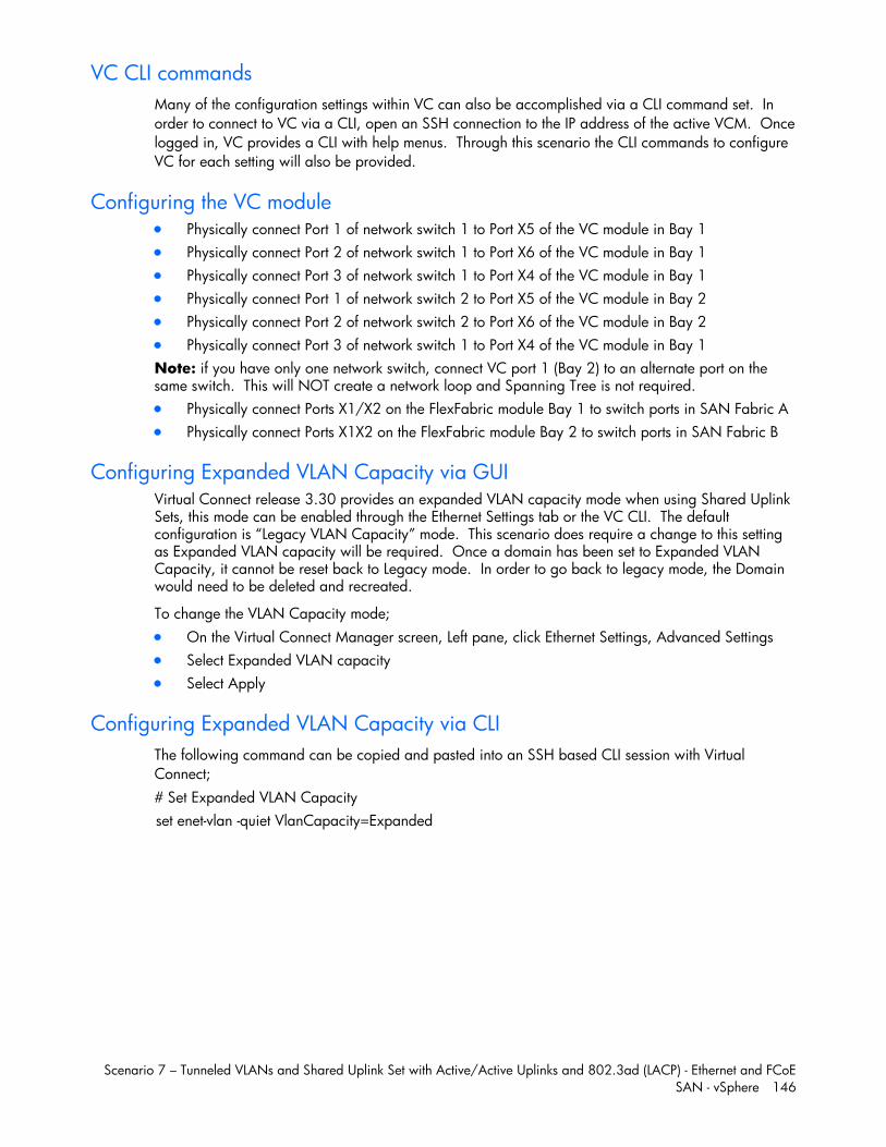
Scenario 7 – Tunneled VLANs and Shared Uplink Set with Active/Active Uplinks and 802.3ad (LACP) - Ethernet and FCoE SAN - vSphere 146
VC CLI commands Many of the configuration settings within VC can also be accomplished via a CLI command set. In order to connect to VC via a CLI, open an SSH connection to the IP address of the active VCM. Once logged in, VC provides a CLI with help menus. Through this scenario the CLI commands to configure VC for each setting will also be provided.
Configuring the VC module Physically connect Port 1 of network switch 1 to Port X5 of the VC module in Bay 1 Physically connect Port 2 of network switch 1 to Port X6 of the VC module in Bay 1 Physically connect Port 3 of network switch 1 to Port X4 of the VC module in Bay 1 Physically connect Port 1 of network switch 2 to Port X5 of the VC module in Bay 2 Physically connect Port 2 of network switch 2 to Port X6 of the VC module in Bay 2 Physically connect Port 3 of network switch 1 to Port X4 of the VC module in Bay 1 Note: if you have only one network switch, connect VC port 1 (Bay 2) to an alternate port on the same switch. This will NOT create a network loop and Spanning Tree is not required. Physically connect Ports X1/X2 on the FlexFabric module Bay 1 to switch ports in SAN Fabric A Physically connect Ports X1X2 on the FlexFabric module Bay 2 to switch ports in SAN Fabric B
Configuring Expanded VLAN Capacity via GUI Virtual Connect release 3.30 provides an expanded VLAN capacity mode when using Shared Uplink Sets, this mode can be enabled through the Ethernet Settings tab or the VC CLI. The default configuration is “Legacy VLAN Capacity” mode. This scenario does require a change to this setting as Expanded VLAN capacity will be required. Once a domain has been set to Expanded VLAN Capacity, it cannot be reset back to Legacy mode. In order to go back to legacy mode, the Domain would need to be deleted and recreated.
To change the VLAN Capacity mode; On the Virtual Connect Manager screen, Left pane, click Ethernet Settings, Advanced Settings Select Expanded VLAN capacity Select Apply
Configuring Expanded VLAN Capacity via CLI The following command can be copied and pasted into an SSH based CLI session with Virtual Connect; # Set Expanded VLAN Capacity set enet-vlan -quiet VlanCapacity=Expanded
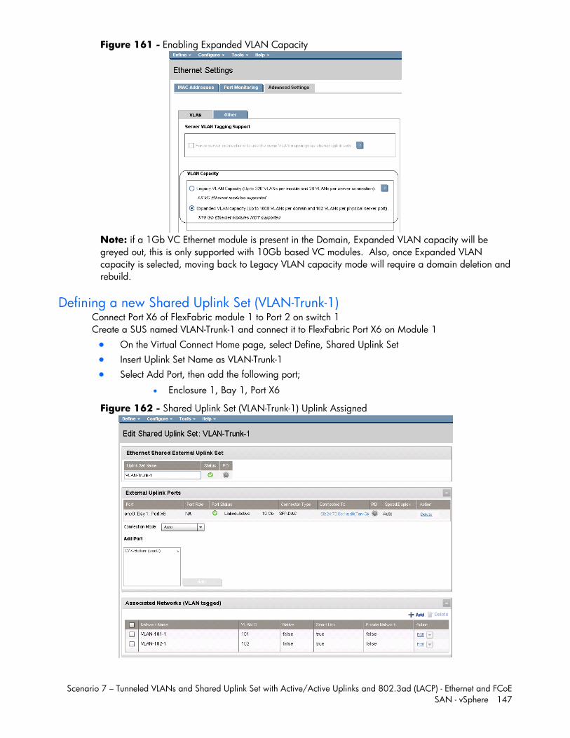
Scenario 7 – Tunneled VLANs and Shared Uplink Set with Active/Active Uplinks and 802.3ad (LACP) - Ethernet and FCoE SAN - vSphere 147
Figure 161 - Enabling Expanded VLAN Capacity
Note: if a 1Gb VC Ethernet module is present in the Domain, Expanded VLAN capacity will be greyed out, this is only supported with 10Gb based VC modules. Also, once Expanded VLAN capacity is selected, moving back to Legacy VLAN capacity mode will require a domain deletion and rebuild.
Defining a new Shared Uplink Set (VLAN-Trunk-1) Connect Port X6 of FlexFabric module 1 to Port 2 on switch 1 Create a SUS named VLAN-Trunk-1 and connect it to FlexFabric Port X6 on Module 1 On the Virtual Connect Home page, select Define, Shared Uplink Set Insert Uplink Set Name as VLAN-Trunk-1 Select Add Port, then add the following port;
Enclosure 1, Bay 1, Port X6
Figure 162 - Shared Uplink Set (VLAN-Trunk-1) Uplink Assigned
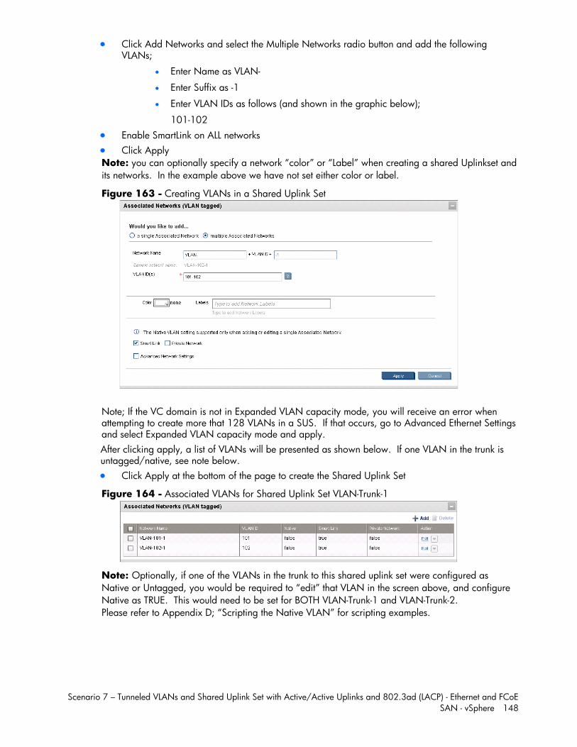
Scenario 7 – Tunneled VLANs and Shared Uplink Set with Active/Active Uplinks and 802.3ad (LACP) - Ethernet and FCoE SAN - vSphere 148
Click Add Networks and select the Multiple Networks radio button and add the following VLANs;
Enter Name as VLAN-
Enter Suffix as -1
Enter VLAN IDs as follows (and shown in the graphic below);
101-102 Enable SmartLink on ALL networks Click Apply Note: you can optionally specify a network “color” or “Label” when creating a shared Uplinkset and its networks. In the example above we have not set either color or label.
Figure 163 - Creating VLANs in a Shared Uplink Set
Note; If the VC domain is not in Expanded VLAN capacity mode, you will receive an error when attempting to create more that 128 VLANs in a SUS. If that occurs, go to Advanced Ethernet Settings and select Expanded VLAN capacity mode and apply. After clicking apply, a list of VLANs will be presented as shown below. If one VLAN in the trunk is untagged/native, see note below. Click Apply at the bottom of the page to create the Shared Uplink Set
Figure 164 - Associated VLANs for Shared Uplink Set VLAN-Trunk-1
Note: Optionally, if one of the VLANs in the trunk to this shared uplink set were configured as Native or Untagged, you would be required to “edit” that VLAN in the screen above, and configure Native as TRUE. This would need to be set for BOTH VLAN-Trunk-1 and VLAN-Trunk-2. Please refer to Appendix D; “Scripting the Native VLAN” for scripting examples.
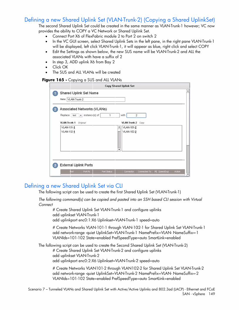
D
D
Scenario 7 –
Defining aThe seprovid
Fig
Defining aThe fo
The foConne
The fo
Tunneled VLAN
a new Shaecond Shareddes the ability
Connect PoIn the VC Gwill be dispEdit the SeassociatedIn step 3, AClick OK The SUS a
ure 165 - C
a new Shaollowing scrip
ollowing commect
# Create Sadd uplinkadd uplink
# Create Nadd netwoVLANIds=1
ollowing scrip# Create Sadd uplinkadd uplink
# Create Nadd netwoVLANIds=1
Ns and Shared
ared Uplind Uplink Set coy to COPY a Vort X6 of FlexFGUI screen, seplayed, left clttings as show VLANs with ADD uplink X6
nd ALL VLANs
Copying a SUS
ared Uplint can be used
mand(s) can b
Shared Uplinkkset VLAN-Trunkport enc0:1:X
Networks VLAork-range -quie101-102 State
t can be usedShared Uplinkkset VLAN-Trunkport enc0:2:X
Networks VLAork-range -quie101-102 State
Uplink Set with
nk Set (VLAould be createVC Network oFabric moduleelect Shared Uick VLAN-Trun
wn below, thehave a suffix 6 from Bay 2
s will be crea
S and ALL VLA
nk Set via d to create the
be copied and
Set VLAN-Trunk-1 X6 Uplinkset=
N-101-1 throet UplinkSet=Ve=enabled Pr
d to create the Set VLAN-Trunk-2 X6 Uplinkset=
N101-2 throuet UplinkSet=Ve=enabled Pr
h Active/Active
AN-Trunk-2ed in the samor Shared Uple 2 to Port 2 oUplink Sets in nk-1, it will ap
e new SUS naof 2
ted
ANs
CLI e first Shared U
d pasted into
unk-1 and con
VLAN-Trunk-1
ugh VLAN-10VLAN-Trunk-1 efSpeedType=
e Second Sharunk-2 and con
VLAN-Trunk-2
ugh VLAN102VLAN-Trunk-2 efSpeedType=
e Uplinks and 8
2) (Copyie manner as Vink Set. on switch 2 the left paneppear as blueme will be VL
Uplink Set (VL
an SSH based
nfigure uplinks
speed=auto
02-1 for Share NamePrefix==auto SmartLi
red Uplink Senfigure uplinks
2 speed=auto
2-2 for Shared NamePrefix==auto SmartLi
802.3ad (LACP
ng a SharVLAN-Trunk-1
, in the right pe, right click aLAN-Trunk-2 a
LAN-Trunk-1)
d CLI session
s
ed Uplink Set =VLAN- Nameink=enabled
et (VLAN-Trunks
d Uplink Set V=VLAN- Nameink=enabled
P) - Ethernet andSAN - vSphere
red Uplink however; VC
pane VLAN-Trnd select CO
and ALL the
with Virtual
VLAN-Trunk-1eSuffix=-1
k-2)
VLAN-Trunk-2 eSuffix=-2
d FCoE e 149
kSet) C now
runk-1 PY
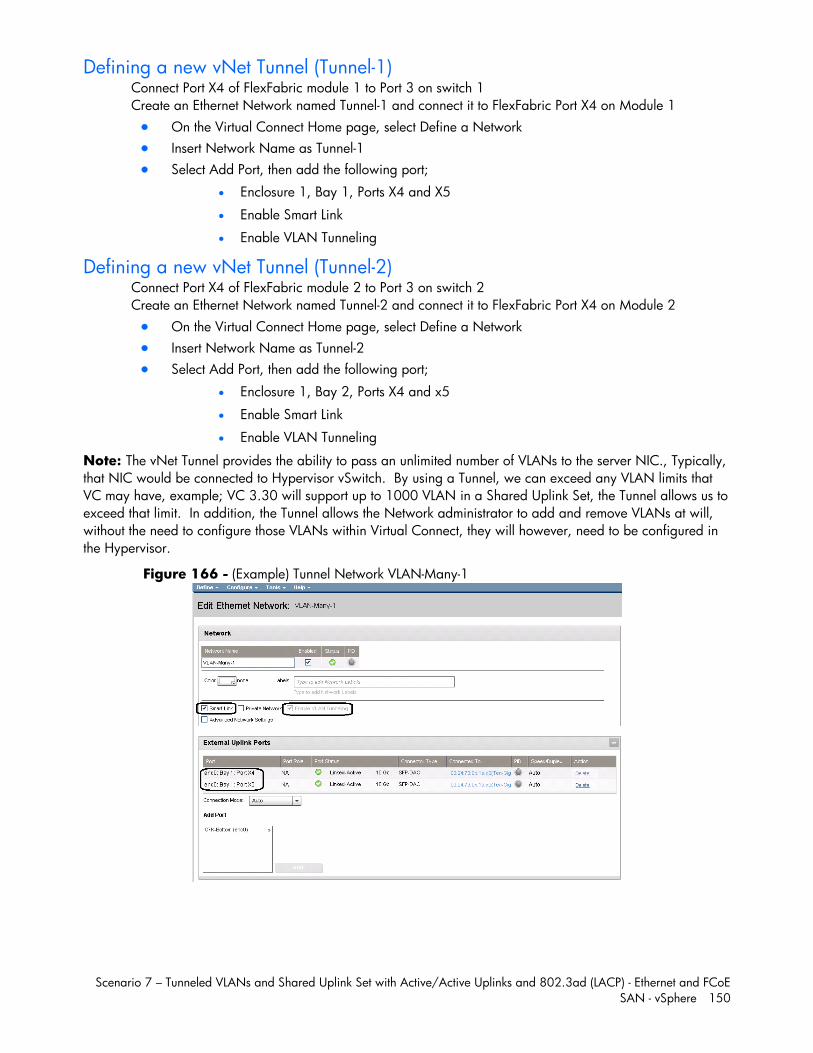
Scenario 7 – Tunneled VLANs and Shared Uplink Set with Active/Active Uplinks and 802.3ad (LACP) - Ethernet and FCoE SAN - vSphere 150
Defining a new vNet Tunnel (Tunnel-1) Connect Port X4 of FlexFabric module 1 to Port 3 on switch 1 Create an Ethernet Network named Tunnel-1 and connect it to FlexFabric Port X4 on Module 1 On the Virtual Connect Home page, select Define a Network Insert Network Name as Tunnel-1 Select Add Port, then add the following port;
Enclosure 1, Bay 1, Ports X4 and X5
Enable Smart Link
Enable VLAN Tunneling
Defining a new vNet Tunnel (Tunnel-2) Connect Port X4 of FlexFabric module 2 to Port 3 on switch 2 Create an Ethernet Network named Tunnel-2 and connect it to FlexFabric Port X4 on Module 2 On the Virtual Connect Home page, select Define a Network Insert Network Name as Tunnel-2 Select Add Port, then add the following port;
Enclosure 1, Bay 2, Ports X4 and x5
Enable Smart Link
Enable VLAN Tunneling
Note: The vNet Tunnel provides the ability to pass an unlimited number of VLANs to the server NIC., Typically, that NIC would be connected to Hypervisor vSwitch. By using a Tunnel, we can exceed any VLAN limits that VC may have, example; VC 3.30 will support up to 1000 VLAN in a Shared Uplink Set, the Tunnel allows us to exceed that limit. In addition, the Tunnel allows the Network administrator to add and remove VLANs at will, without the need to configure those VLANs within Virtual Connect, they will however, need to be configured in the Hypervisor.
Figure 166 - (Example) Tunnel Network VLAN-Many-1
Scenario 7 – Tunneled VLANs and Shared Uplink Set with Active/Active Uplinks and 802.3ad (LACP) - Ethernet and FCoE SAN - vSphere 151
Defining a new Network Tunnel via CLI The following script can be used to create the vNet Tunnel (Tunnel-1)
The following command(s) can be copied and pasted into an SSH based CLI session with Virtual Connect
# Create vNet Tunnel "Tunnel-1" and configure uplinks add network Tunnel-1 VLanTunnel=Enabled add uplinkport enc0:1:X4 Network=Tunnel-1 add uplinkport enc0:1:X5 Network=Tunnel-1 Set network Tunnel-1 SmartLink=Enabled
# Create vNet Tunnel "Tunnel-2" and configure uplinks add network Tunnel-2 VLanTunnel=Enabled add uplinkport enc0:2:X4 Network=Tunnel-2 add uplinkport enc0:2:X5 Network=Tunnel-2 Set network Tunnel-2 SmartLink=Enabled
Summary Note: In this scenario we have created two independent Share Uplink Sets (SUS), each originating from the opposite FlexFabric Modules, by doing so we provide the ability to create separate and redundant connections out of the Virtual Connect domain. When we create the server profiles, you will see how the NICs will connect to VLANs accessed through the opposite VC module, which provides the ability to create an Active / Active uplink scenario. Alternatively, we could have created a single SUS and assigned both sets of these uplink ports to the same SUS, however, this would have provided an Active/Standby uplink scenario, as shown in Scenario 5.
In addition to the Shared Uplink Set, we also created a pair of vNet (Network) Tunnels. The Tunnel can be used to pass many VLANs (up to 4094 VLANs) without the need to define each VLAN, as in the Shared Uplink Set.
Defining a new (FCoE) SAN Fabric via GUI Create a Fabric and name it “FCoE_A” On the Virtual Connect Manager screen, click Define, SAN Fabric to create the first Fabric Enter the Network Name of “FCoE_A” Select Add Port, then add the following ports;
Enclosure 1, Bay 1, Port X1 Enclosure 1, Bay 1, Port X2
Select the Advanced Settings Select Automatic Login Re-Distribution
Select Apply
Create a second Fabric and name it “FCoE_B” On the Virtual Connect Manager screen, click Define, SAN Fabric to create the second Fabric Enter the Network Name of “FCoE_B” Select Add Port, then add the following ports;
Enclosure 1, Bay 2, Port X1 Enclosure 1, Bay 2, Port X2
Select the Advanced Settings Select Automatic Login Re-Distribution
Select Apply
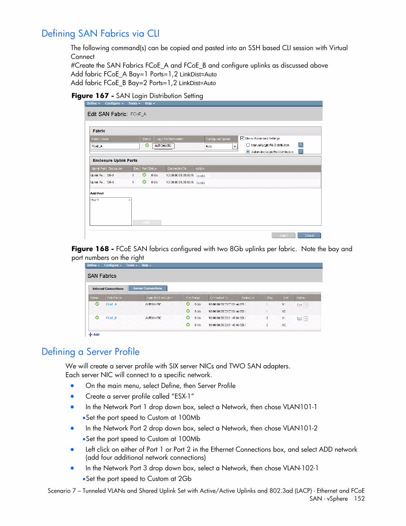
Scenario 7 – Tunneled VLANs and Shared Uplink Set with Active/Active Uplinks and 802.3ad (LACP) - Ethernet and FCoE SAN - vSphere 152
Defining SAN Fabrics via CLI The following command(s) can be copied and pasted into an SSH based CLI session with Virtual Connect #Create the SAN Fabrics FCoE_A and FCoE_B and configure uplinks as discussed above Add fabric FCoE_A Bay=1 Ports=1,2 LinkDist=Auto Add fabric FCoE_B Bay=2 Ports=1,2 LinkDist=Auto
Figure 167 - SAN Login Distribution Setting
Figure 168 - FCoE SAN fabrics configured with two 8Gb uplinks per fabric. Note the bay and port numbers on the right
Defining a Server Profile We will create a server profile with SIX server NICs and TWO SAN adapters. Each server NIC will connect to a specific network. On the main menu, select Define, then Server Profile Create a server profile called “ESX-1” In the Network Port 1 drop down box, select a Network, then chose VLAN101-1
Set the port speed to Custom at 100Mb In the Network Port 2 drop down box, select a Network, then chose VLAN101-2
Set the port speed to Custom at 100Mb Left click on either of Port 1 or Port 2 in the Ethernet Connections box, and select ADD network
(add four additional network connections) In the Network Port 3 drop down box, select a Network, then chose VLAN-102-1
Set the port speed to Custom at 2Gb
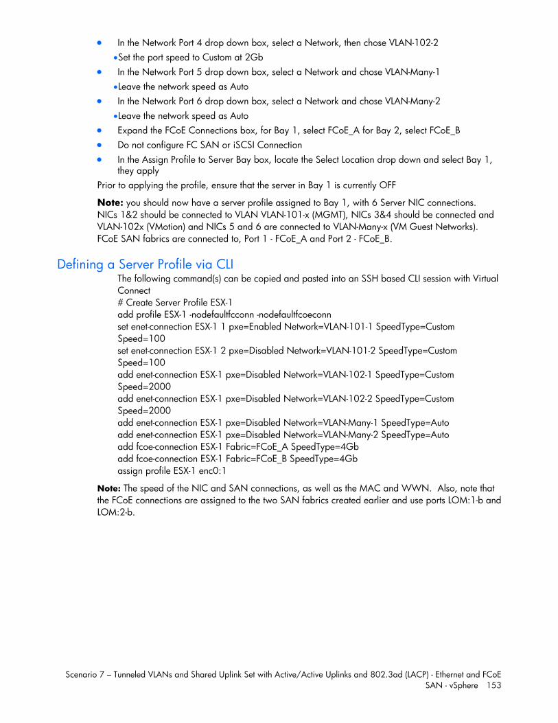
Scenario 7 – Tunneled VLANs and Shared Uplink Set with Active/Active Uplinks and 802.3ad (LACP) - Ethernet and FCoE SAN - vSphere 153
In the Network Port 4 drop down box, select a Network, then chose VLAN-102-2 Set the port speed to Custom at 2Gb
In the Network Port 5 drop down box, select a Network and chose VLAN-Many-1 Leave the network speed as Auto
In the Network Port 6 drop down box, select a Network and chose VLAN-Many-2 Leave the network speed as Auto
Expand the FCoE Connections box, for Bay 1, select FCoE_A for Bay 2, select FCoE_B Do not configure FC SAN or iSCSI Connection In the Assign Profile to Server Bay box, locate the Select Location drop down and select Bay 1,
they apply Prior to applying the profile, ensure that the server in Bay 1 is currently OFF
Note: you should now have a server profile assigned to Bay 1, with 6 Server NIC connections. NICs 1&2 should be connected to VLAN VLAN-101-x (MGMT), NICs 3&4 should be connected and VLAN-102x (VMotion) and NICs 5 and 6 are connected to VLAN-Many-x (VM Guest Networks). FCoE SAN fabrics are connected to, Port 1 - FCoE_A and Port 2 - FCoE_B.
Defining a Server Profile via CLI The following command(s) can be copied and pasted into an SSH based CLI session with Virtual Connect # Create Server Profile ESX-1 add profile ESX-1 -nodefaultfcconn -nodefaultfcoeconn set enet-connection ESX-1 1 pxe=Enabled Network=VLAN-101-1 SpeedType=Custom Speed=100 set enet-connection ESX-1 2 pxe=Disabled Network=VLAN-101-2 SpeedType=Custom Speed=100 add enet-connection ESX-1 pxe=Disabled Network=VLAN-102-1 SpeedType=Custom Speed=2000 add enet-connection ESX-1 pxe=Disabled Network=VLAN-102-2 SpeedType=Custom Speed=2000 add enet-connection ESX-1 pxe=Disabled Network=VLAN-Many-1 SpeedType=Auto add enet-connection ESX-1 pxe=Disabled Network=VLAN-Many-2 SpeedType=Auto add fcoe-connection ESX-1 Fabric=FCoE_A SpeedType=4Gb add fcoe-connection ESX-1 Fabric=FCoE_B SpeedType=4Gb assign profile ESX-1 enc0:1
Note: The speed of the NIC and SAN connections, as well as the MAC and WWN. Also, note that the FCoE connections are assigned to the two SAN fabrics created earlier and use ports LOM:1-b and LOM:2-b.
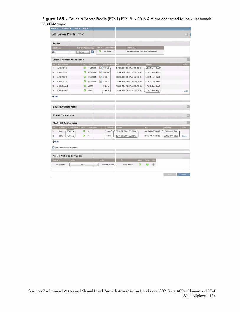
Scenario 7 –
FigVLA
Tunneled VLAN
ure 169 - DAN-Many-x
Ns and Shared
Define a Serve
Uplink Set with
er Profile (ESX-
h Active/Active
-1) ESXi 5 NIC
e Uplinks and 8
Cs 5 & 6 are
802.3ad (LACP
connected to
P) - Ethernet andSAN - vSphere
o the vNet tunn
d FCoE e 154
nels
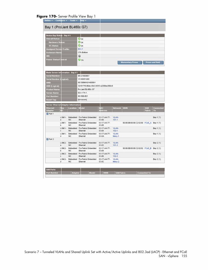
Scenario 7 –
Fig
Tunneled VLAN
ure 170- Se
Ns and Shared
erver Profile V
Uplink Set with
View Bay 1
h Active/Activee Uplinks and 8802.3ad (LACPP) - Ethernet andSAN - vSphere
d FCoE e 155
Scenario 7 – Tunneled VLANs and Shared Uplink Set with Active/Active Uplinks and 802.3ad (LACP) - Ethernet and FCoE SAN - vSphere 156
Review In this scenario we have created Two Shared Uplink Sets (SUS), providing support for several VLANs. Uplinks originating from each FlexFabric Module connect to each SUS, by doing so we provide redundant connections out of the Virtual Connect domain. As multiple uplinks are used for each SUS, we have also leveraged LACP to improved uplink performance. Additionally, we have created a pair of vNet Network Tunnels. These Tunnels will provide the ability to transparently pass any and all VLANs between the connected servers and network switches. In this scenario, all uplinks will be active. We also create two FCoE SAN Fabrics. We created a server profile, with FOUR NICs. Two connected to VLANs 101 (untagged) and 102 Tagged), Port 1 connects to VLAN-101-1 and VLAN-102-1and Port 2 connects to VLAN-101-2 and VLAN-102-2, which provides the ability to sustain a link or module failure and not loose connection to the network, these NICs were set to 2Gb/Sec. VLAN-101-1 and VLAN-101-2 are configured to support VLAN 101, frames will be presented to the NIC(s) without VLAN tags (untagged), VLAN-102-1 and VLAN-102-2 are configured to support VLAN 102, frames will be presented to the NIC(s) with VLAN tags (tagged) these two NICs are connected to the same VLAN, but taking a different path out of the enclosure. VLAN 101 is used for Management connections to the ESX host and VLAN 102 is used for VMotion. Network Ports 3 and 4 connect to the vNet Network Tunnels, Port 3 connects to Tunnel-1 and Port 4 connects to Tunnel-2, which provides the ability to sustain a link or module failure and not loose connection to the network, these NICs were set to 4Gb/Sec. All frames presented to VC through this network will be presented to the connected server NICs. All frames will be tagged, a vNet Tunnel will pass an unlimited number of VLANs. Additionally, FCoE port 1 is connected to SAN fabric FCoE_A and FCoE SAN port 2 is connected to SAN Fabric FCoE_B, providing a multi-pathed connected to the SAN. The SAN fabric connections are set to 4Gb/Sec. The FCoE SAN fabric connects to each SAN fabric over a pair of uplinks per module. SAN logins are distributed across the multiple paths.
Results – vSphere Networking Examples We successfully configured FlexFabric with Share Uplink Sets, supporting several VLANs and redundant SAN fabrics. We created a server profile to connect to the various vNet with SIX NICs and the SAN fabrics using the FCoE connections created within the profile.
Although both Ethernet and Fibre channel connectivity is provided by the CNA adapter used in the G7 servers; each capability (LAN and SAN) is provided by a different component of the adapter, they appear in the server as individual network and SAN adapters.
The following graphics show an ESXi 5 server with SIX FlexNICs configured, two at 100Mb (console), two at 2Gb (VMotion) and two at 3.9Gb (Guests port groups). If we did not require SAN connectivity on this server, the FCoE connections could be deleted and the server would then have 8 NIC ports available to the OS. In addition, if we did not want FCoE connectivity and instead wanted to leverage iSCSI, we could delete the FCoE connected and re-create those connects as iSCSI connections, with offload and optionally iSCSI boot.
Note: the BL465c G7 and BL685c G7 utilize an NC551i chipset (BE2), whereas the BL460c G7, BL620c G6 and BL680c G7 utilize an NC553i chipset (BE3). Both the BE2 and BE3 chipsets share common drivers and firmware.
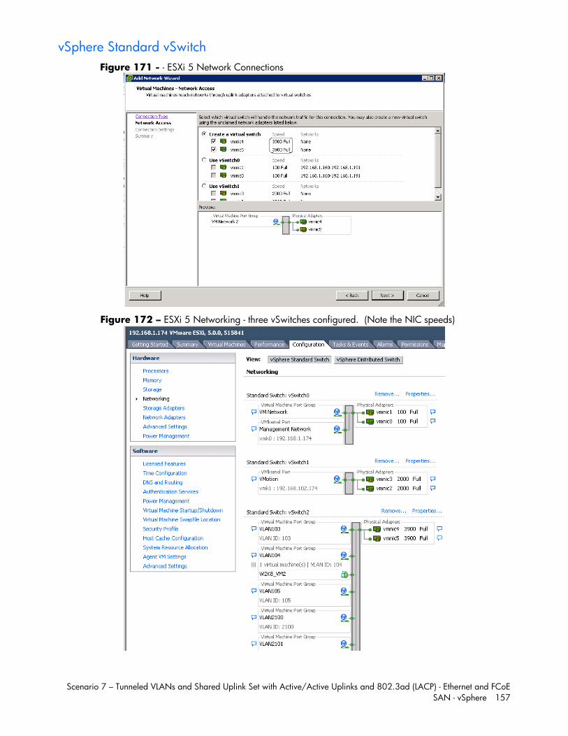
Scenario 7 – Tunneled VLANs and Shared Uplink Set with Active/Active Uplinks and 802.3ad (LACP) - Ethernet and FCoE SAN - vSphere 157
vSphere Standard vSwitch Figure 171 - - ESXi 5 Network Connections
Figure 172 – ESXi 5 Networking - three vSwitches configured. (Note the NIC speeds)
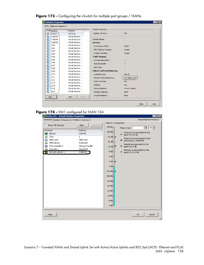
Scenario 7 – Tunneled VLANs and Shared Uplink Set with Active/Active Uplinks and 802.3ad (LACP) - Ethernet and FCoE SAN - vSphere 158
Figure 173 - Configuring the vSwitch for multiple port groups / VLANs
Figure 174 - VM1 configured for VLAN 104

Scenario 7 – Tunneled VLANs and Shared Uplink Set with Active/Active Uplinks and 802.3ad (LACP) - Ethernet and FCoE SAN - vSphere 159
Figure 175 - VM1 on VLAN 104
vSphere Distributed vSwitch Figure 176 - Management and VMotion NICs are connected to Standard vSwitches
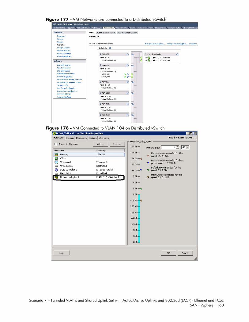
Scenario 7 – Tunneled VLANs and Shared Uplink Set with Active/Active Uplinks and 802.3ad (LACP) - Ethernet and FCoE SAN - vSphere 160
Figure 177 - VM Networks are connected to a Distributed vSwitch
Figure 178 - VM Connected to VLAN 104 on Distributed vSwitch

Scenario 7 – Tunneled VLANs and Shared Uplink Set with Active/Active Uplinks and 802.3ad (LACP) - Ethernet and FCoE SAN - vSphere 161
Results – vSphere SAN Connectivity Figure 179 - During server boot, you can see that Port 1 of the FlexHBA is connected to an EVA SAN LUN. Also note the CNA firmware version, this is the minimum version required for vSphere 5.
Figure 180 – ESXi 5 storage configuration, the Shared Storage LUN is provided through the FCoE connections to the SAN.
Scenario 7 – Tunneled VLANs and Shared Uplink Set with Active/Active Uplinks and 802.3ad (LACP) - Ethernet and FCoE SAN - vSphere 162
Summary We presented a Virtual Connect Network scenario by creating two shared uplink sets (SUS), each SUS is connected with TWO active uplinks; both SUS’ can actively pass traffic. We included a dual path SAN fabric for storage connectivity.
When VC profile ESX-1 is applied to the server in bay1 and is powered up, it has one NIC connected through FlexFabric module 1 (connected to VLAN-101-1), the second NIC is connected through FlexFabric module 2 (connected to VLAN-101-2). Each NIC is configured at 100Mb. These NICs are connected to the console vSwitch. The second pair of NICs are connected to the second vSwitch, which is configured for VMotion and is connected to VLAN-102-x through NICs 3 and 4 which are configured at 2Gb. The last pair of NICs 5 and 6, are configured at 3.9Gb and connected to the third vSwitch, which is configured to support VLANs 103 through 105 and 210 through 2150. This host is also configured for FCoE based SAN access and connects to a SAN LUN to store the Guest VMs. Each FCoE port is configured for 4Gb of SAN bandwidth.
We successfully configured FlexFabric with Share Uplink Sets, supporting several VLANs and redundant SAN fabrics. We created a server profile to connect to the various vNet with SIX NICs and the SAN fabrics using the FCoE connections created within the profile.
As additional servers are added to the enclosure, simply create additional profiles, or copy existing profiles, configure the NICs for LAN and SAN fabrics as required and apply them to the appropriate server bays and power the server on.
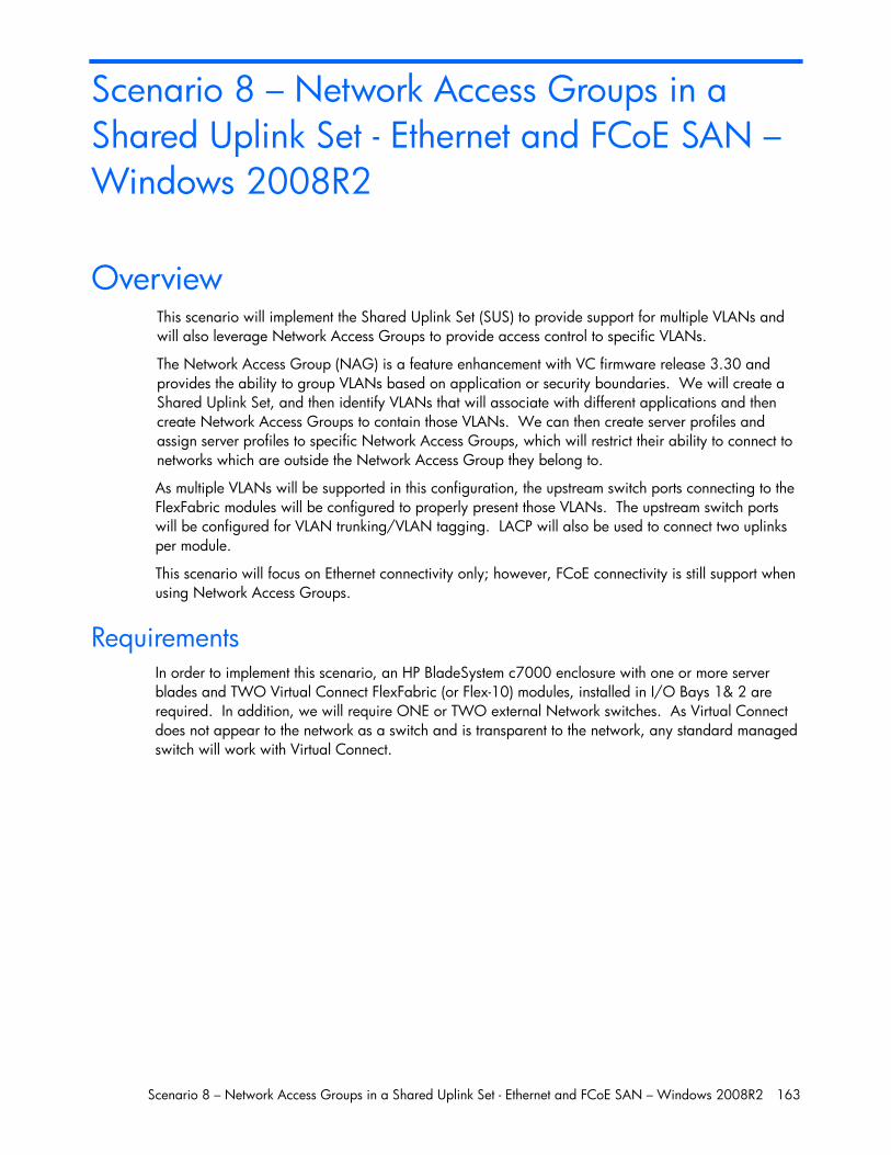
Scenario 8 – Network Access Groups in a Shared Uplink Set - Ethernet and FCoE SAN – Windows 2008R2 163
Scenario 8 – Network Access Groups in a Shared Uplink Set - Ethernet and FCoE SAN – Windows 2008R2
Overview This scenario will implement the Shared Uplink Set (SUS) to provide support for multiple VLANs and will also leverage Network Access Groups to provide access control to specific VLANs.
The Network Access Group (NAG) is a feature enhancement with VC firmware release 3.30 and provides the ability to group VLANs based on application or security boundaries. We will create a Shared Uplink Set, and then identify VLANs that will associate with different applications and then create Network Access Groups to contain those VLANs. We can then create server profiles and assign server profiles to specific Network Access Groups, which will restrict their ability to connect to networks which are outside the Network Access Group they belong to.
As multiple VLANs will be supported in this configuration, the upstream switch ports connecting to the FlexFabric modules will be configured to properly present those VLANs. The upstream switch ports will be configured for VLAN trunking/VLAN tagging. LACP will also be used to connect two uplinks per module.
This scenario will focus on Ethernet connectivity only; however, FCoE connectivity is still support when using Network Access Groups.
Requirements In order to implement this scenario, an HP BladeSystem c7000 enclosure with one or more server blades and TWO Virtual Connect FlexFabric (or Flex-10) modules, installed in I/O Bays 1& 2 are required. In addition, we will require ONE or TWO external Network switches. As Virtual Connect does not appear to the network as a switch and is transparent to the network, any standard managed switch will work with Virtual Connect.
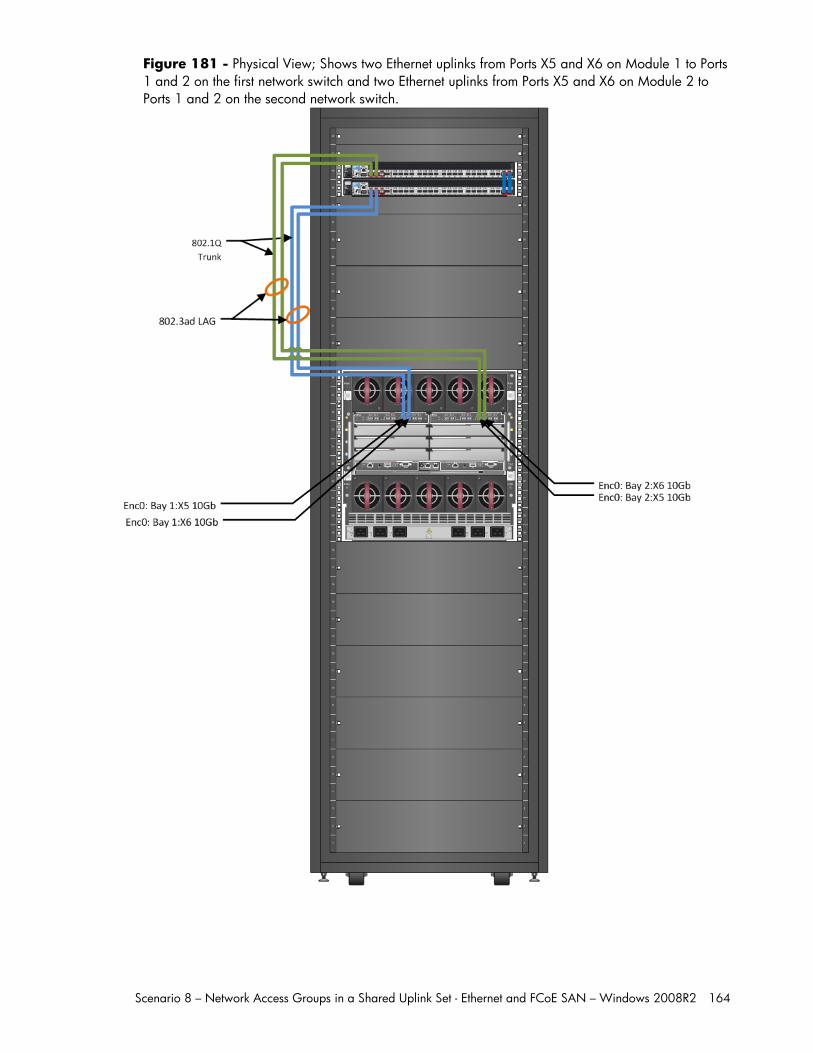
Scenario 8 – Network Access Groups in a Shared Uplink Set - Ethernet and FCoE SAN – Windows 2008R2 164
Figure 181 - Physical View; Shows two Ethernet uplinks from Ports X5 and X6 on Module 1 to Ports 1 and 2 on the first network switch and two Ethernet uplinks from Ports X5 and X6 on Module 2 to Ports 1 and 2 on the second network switch.
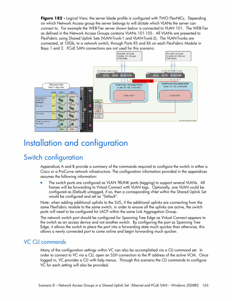
Scenario 8 – Network Access Groups in a Shared Uplink Set - Ethernet and FCoE SAN – Windows 2008R2 165
Figure 182 - Logical View; the server blade profile is configured with TWO FlexNICs. Depending on which Network Access group the server belongs to will dictate which VLANs the server can connect to. For example the WEB-Tier server shown below is connected to VLAN 101. The WEB-Tier as defined in the Network Access Groups contains VLANs 101-105. All VLANs are presented to FlexFabric using Shared Uplink Sets (VLAN-Trunk-1 and VLAN-Trunk-2). The VLAN-Trunks are connected, at 10Gb, to a network switch, through Ports X5 and X6 on each FlexFabric Module in Bays 1 and 2. FCoE SAN connections are not used for this scenario.
Installation and configuration
Switch configuration Appendices A and B provide a summary of the commands required to configure the switch in either a Cisco or a ProCurve network infrastructure. The configuration information provided in the appendices assumes the following information: The switch ports are configured as VLAN TRUNK ports (tagging) to support several VLANs. All
frames will be forwarding to Virtual Connect with VLAN tags. Optionally, one VLAN could be configured as (Default) untagged, if so, then a corresponding vNet within the Shared Uplink Set would be configured and set as “Default”.
Note: when adding additional uplinks to the SUS, if the additional uplinks are connecting from the same FlexFabric module to the same switch, in order to ensure all the uplinks are active, the switch ports will need to be configured for LACP within the same Link Aggregation Group. The network switch port should be configured for Spanning Tree Edge as Virtual Connect appears to the switch as an access device and not another switch. By configuring the port as Spanning Tree Edge, it allows the switch to place the port into a forwarding state much quicker than otherwise, this allows a newly connected port to come online and begin forwarding much quicker.
VC CLI commands Many of the configuration settings within VC can also be accomplished via a CLI command set. In order to connect to VC via a CLI, open an SSH connection to the IP address of the active VCM. Once logged in, VC provides a CLI with help menus. Through this scenario the CLI commands to configure VC for each setting will also be provided.
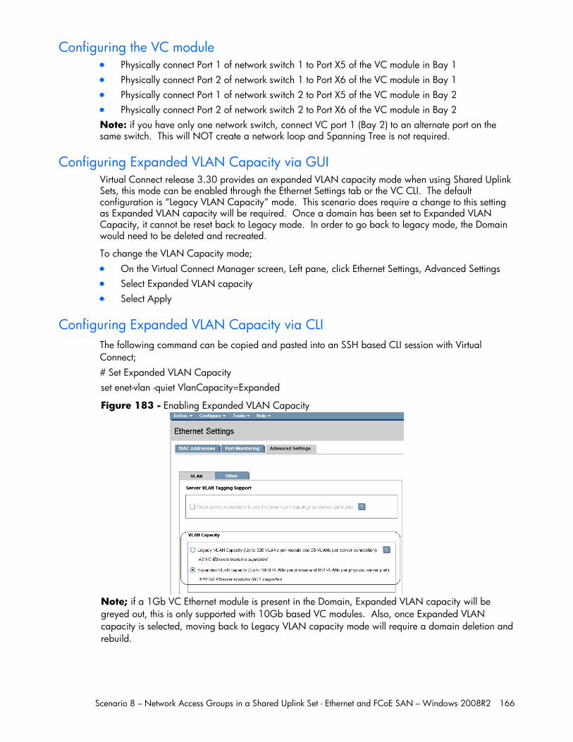
Scenario 8 – Network Access Groups in a Shared Uplink Set - Ethernet and FCoE SAN – Windows 2008R2 166
Configuring the VC module Physically connect Port 1 of network switch 1 to Port X5 of the VC module in Bay 1 Physically connect Port 2 of network switch 1 to Port X6 of the VC module in Bay 1 Physically connect Port 1 of network switch 2 to Port X5 of the VC module in Bay 2 Physically connect Port 2 of network switch 2 to Port X6 of the VC module in Bay 2 Note: if you have only one network switch, connect VC port 1 (Bay 2) to an alternate port on the same switch. This will NOT create a network loop and Spanning Tree is not required.
Configuring Expanded VLAN Capacity via GUI Virtual Connect release 3.30 provides an expanded VLAN capacity mode when using Shared Uplink Sets, this mode can be enabled through the Ethernet Settings tab or the VC CLI. The default configuration is “Legacy VLAN Capacity” mode. This scenario does require a change to this setting as Expanded VLAN capacity will be required. Once a domain has been set to Expanded VLAN Capacity, it cannot be reset back to Legacy mode. In order to go back to legacy mode, the Domain would need to be deleted and recreated.
To change the VLAN Capacity mode; On the Virtual Connect Manager screen, Left pane, click Ethernet Settings, Advanced Settings Select Expanded VLAN capacity Select Apply
Configuring Expanded VLAN Capacity via CLI The following command can be copied and pasted into an SSH based CLI session with Virtual Connect; # Set Expanded VLAN Capacity set enet-vlan -quiet VlanCapacity=Expanded
Figure 183 - Enabling Expanded VLAN Capacity
Note; if a 1Gb VC Ethernet module is present in the Domain, Expanded VLAN capacity will be greyed out, this is only supported with 10Gb based VC modules. Also, once Expanded VLAN capacity is selected, moving back to Legacy VLAN capacity mode will require a domain deletion and rebuild.
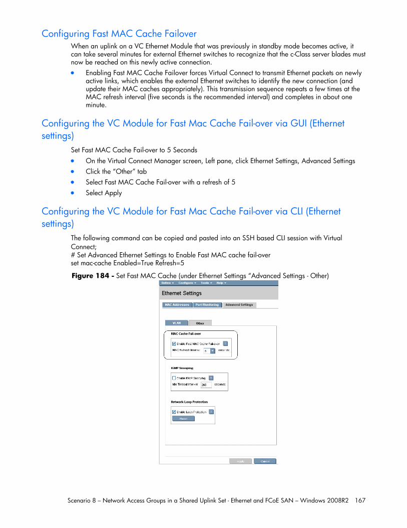
Scenario 8 – Network Access Groups in a Shared Uplink Set - Ethernet and FCoE SAN – Windows 2008R2 167
Configuring Fast MAC Cache Failover When an uplink on a VC Ethernet Module that was previously in standby mode becomes active, it can take several minutes for external Ethernet switches to recognize that the c-Class server blades must now be reached on this newly active connection. Enabling Fast MAC Cache Failover forces Virtual Connect to transmit Ethernet packets on newly
active links, which enables the external Ethernet switches to identify the new connection (and update their MAC caches appropriately). This transmission sequence repeats a few times at the MAC refresh interval (five seconds is the recommended interval) and completes in about one minute.
Configuring the VC Module for Fast Mac Cache Fail-over via GUI (Ethernet settings)
Set Fast MAC Cache Fail-over to 5 Seconds On the Virtual Connect Manager screen, Left pane, click Ethernet Settings, Advanced Settings Click the “Other” tab Select Fast MAC Cache Fail-over with a refresh of 5 Select Apply
Configuring the VC Module for Fast Mac Cache Fail-over via CLI (Ethernet settings)
The following command can be copied and pasted into an SSH based CLI session with Virtual Connect; # Set Advanced Ethernet Settings to Enable Fast MAC cache fail-over set mac-cache Enabled=True Refresh=5
Figure 184 - Set Fast MAC Cache (under Ethernet Settings “Advanced Settings - Other)

Scenario 8 – Network Access Groups in a Shared Uplink Set - Ethernet and FCoE SAN – Windows 2008R2 168
Defining a new Shared Uplink Set (VLAN-Trunk-1) Connect Ports X5 and X6 of FlexFabric module 1 to Ports 1 and 2 on switch 1 Create a SUS named VLAN-Trunk-1 and connect it to FlexFabric Ports X5 and X6 on Module 1 On the Virtual Connect Home page, select Define, Shared Uplink Set Insert Uplink Set Name as VLAN-Trunk-1 Select Add Port, then add the following port;
Enclosure 1, Bay 1, Port X5
Enclosure 1, Bay 1, Port X6
Figure 185 - Shared Uplink Set (VLAN-Trunk-1) Uplinks Assigned
Click Add Networks and select the Multiple Networks radio button and add the following
VLANs; Enter Name as VLAN- Enter Suffix as -1 Enter VLAN IDs as follows (and shown in the graphic below);
101-105,2100-2400 Enable SmartLink on ALL networks Click Apply
Note: you can optionally specify a network “color” or “Label” when creating a shared Uplinkset and its networks. In the example above we have not set either color or label.
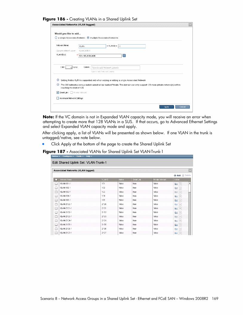
Scenario 8 – Network Access Groups in a Shared Uplink Set - Ethernet and FCoE SAN – Windows 2008R2 169
Figure 186 - Creating VLANs in a Shared Uplink Set
Note: If the VC domain is not in Expanded VLAN capacity mode, you will receive an error when attempting to create more that 128 VLANs in a SUS. If that occurs, go to Advanced Ethernet Settings and select Expanded VLAN capacity mode and apply. After clicking apply, a list of VLANs will be presented as shown below. If one VLAN in the trunk is untagged/native, see note below. Click Apply at the bottom of the page to create the Shared Uplink Set
Figure 187 - Associated VLANs for Shared Uplink Set VLAN-Trunk-1
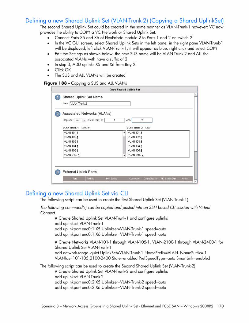
Scenario 8 – Network Access Groups in a Shared Uplink Set - Ethernet and FCoE SAN – Windows 2008R2 170
Defining a new Shared Uplink Set (VLAN-Trunk-2) (Copying a Shared UplinkSet) The second Shared Uplink Set could be created in the same manner as VLAN-Trunk-1 however; VC now provides the ability to COPY a VC Network or Shared Uplink Set.
Connect Ports X5 and X6 of FlexFabric module 2 to Ports 1 and 2 on switch 2 In the VC GUI screen, select Shared Uplink Sets in the left pane, in the right pane VLAN-Trunk-1
will be displayed, left click VLAN-Trunk-1, it will appear as blue, right click and select COPY Edit the Settings as shown below, the new SUS name will be VLAN-Trunk-2 and ALL the
associated VLANs with have a suffix of 2 In step 3, ADD uplinks X5 and X6 from Bay 2 Click OK The SUS and ALL VLANs will be created
Figure 188 - Copying a SUS and ALL VLANs
Defining a new Shared Uplink Set via CLI The following script can be used to create the first Shared Uplink Set (VLAN-Trunk-1)
The following command(s) can be copied and pasted into an SSH based CLI session with Virtual Connect
# Create Shared Uplink Set VLAN-Trunk-1 and configure uplinks add uplinkset VLAN-Trunk-1 add uplinkport enc0:1:X5 Uplinkset=VLAN-Trunk-1 speed=auto add uplinkport enc0:1:X6 Uplinkset=VLAN-Trunk-1 speed=auto
# Create Networks VLAN-101-1 through VLAN-105-1, VLAN-2100-1 through VLAN-2400-1 for Shared Uplink Set VLAN-Trunk-1 add network-range -quiet UplinkSet=VLAN-Trunk-1 NamePrefix=VLAN- NameSuffix=-1 VLANIds=101-105,2100-2400 State=enabled PrefSpeedType=auto SmartLink=enabled
The following script can be used to create the Second Shared Uplink Set (VLAN-Trunk-2) # Create Shared Uplink Set VLAN-Trunk-2 and configure uplinks add uplinkset VLAN-Trunk-2 add uplinkport enc0:2:X5 Uplinkset=VLAN-Trunk-2 speed=auto add uplinkport enc0:2:X6 Uplinkset=VLAN-Trunk-2 speed=auto
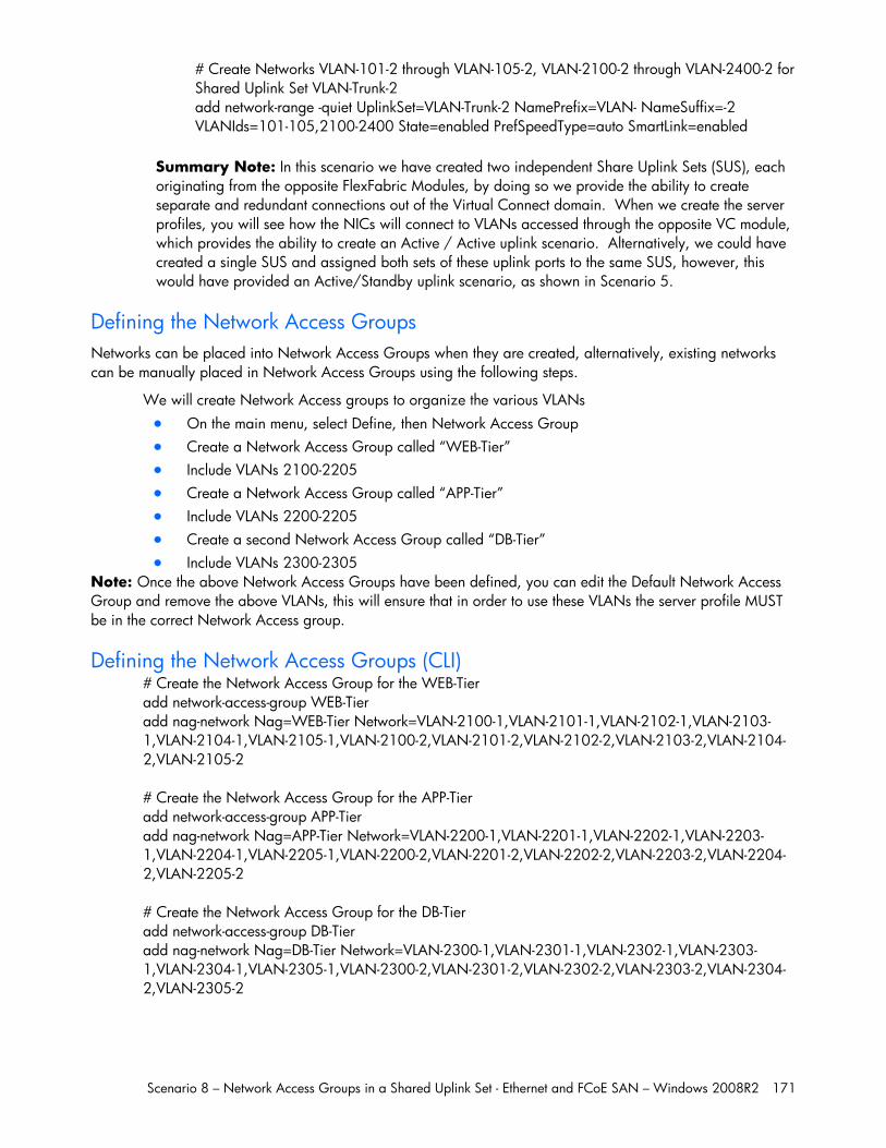
Scenario 8 – Network Access Groups in a Shared Uplink Set - Ethernet and FCoE SAN – Windows 2008R2 171
# Create Networks VLAN-101-2 through VLAN-105-2, VLAN-2100-2 through VLAN-2400-2 for Shared Uplink Set VLAN-Trunk-2 add network-range -quiet UplinkSet=VLAN-Trunk-2 NamePrefix=VLAN- NameSuffix=-2 VLANIds=101-105,2100-2400 State=enabled PrefSpeedType=auto SmartLink=enabled
Summary Note: In this scenario we have created two independent Share Uplink Sets (SUS), each originating from the opposite FlexFabric Modules, by doing so we provide the ability to create separate and redundant connections out of the Virtual Connect domain. When we create the server profiles, you will see how the NICs will connect to VLANs accessed through the opposite VC module, which provides the ability to create an Active / Active uplink scenario. Alternatively, we could have created a single SUS and assigned both sets of these uplink ports to the same SUS, however, this would have provided an Active/Standby uplink scenario, as shown in Scenario 5.
Defining the Network Access Groups Networks can be placed into Network Access Groups when they are created, alternatively, existing networks can be manually placed in Network Access Groups using the following steps.
We will create Network Access groups to organize the various VLANs On the main menu, select Define, then Network Access Group Create a Network Access Group called “WEB-Tier” Include VLANs 2100-2205 Create a Network Access Group called “APP-Tier” Include VLANs 2200-2205 Create a second Network Access Group called “DB-Tier” Include VLANs 2300-2305
Note: Once the above Network Access Groups have been defined, you can edit the Default Network Access Group and remove the above VLANs, this will ensure that in order to use these VLANs the server profile MUST be in the correct Network Access group.
Defining the Network Access Groups (CLI) # Create the Network Access Group for the WEB-Tier add network-access-group WEB-Tier add nag-network Nag=WEB-Tier Network=VLAN-2100-1,VLAN-2101-1,VLAN-2102-1,VLAN-2103-1,VLAN-2104-1,VLAN-2105-1,VLAN-2100-2,VLAN-2101-2,VLAN-2102-2,VLAN-2103-2,VLAN-2104-2,VLAN-2105-2 # Create the Network Access Group for the APP-Tier add network-access-group APP-Tier add nag-network Nag=APP-Tier Network=VLAN-2200-1,VLAN-2201-1,VLAN-2202-1,VLAN-2203-1,VLAN-2204-1,VLAN-2205-1,VLAN-2200-2,VLAN-2201-2,VLAN-2202-2,VLAN-2203-2,VLAN-2204-2,VLAN-2205-2 # Create the Network Access Group for the DB-Tier add network-access-group DB-Tier add nag-network Nag=DB-Tier Network=VLAN-2300-1,VLAN-2301-1,VLAN-2302-1,VLAN-2303-1,VLAN-2304-1,VLAN-2305-1,VLAN-2300-2,VLAN-2301-2,VLAN-2302-2,VLAN-2303-2,VLAN-2304-2,VLAN-2305-2
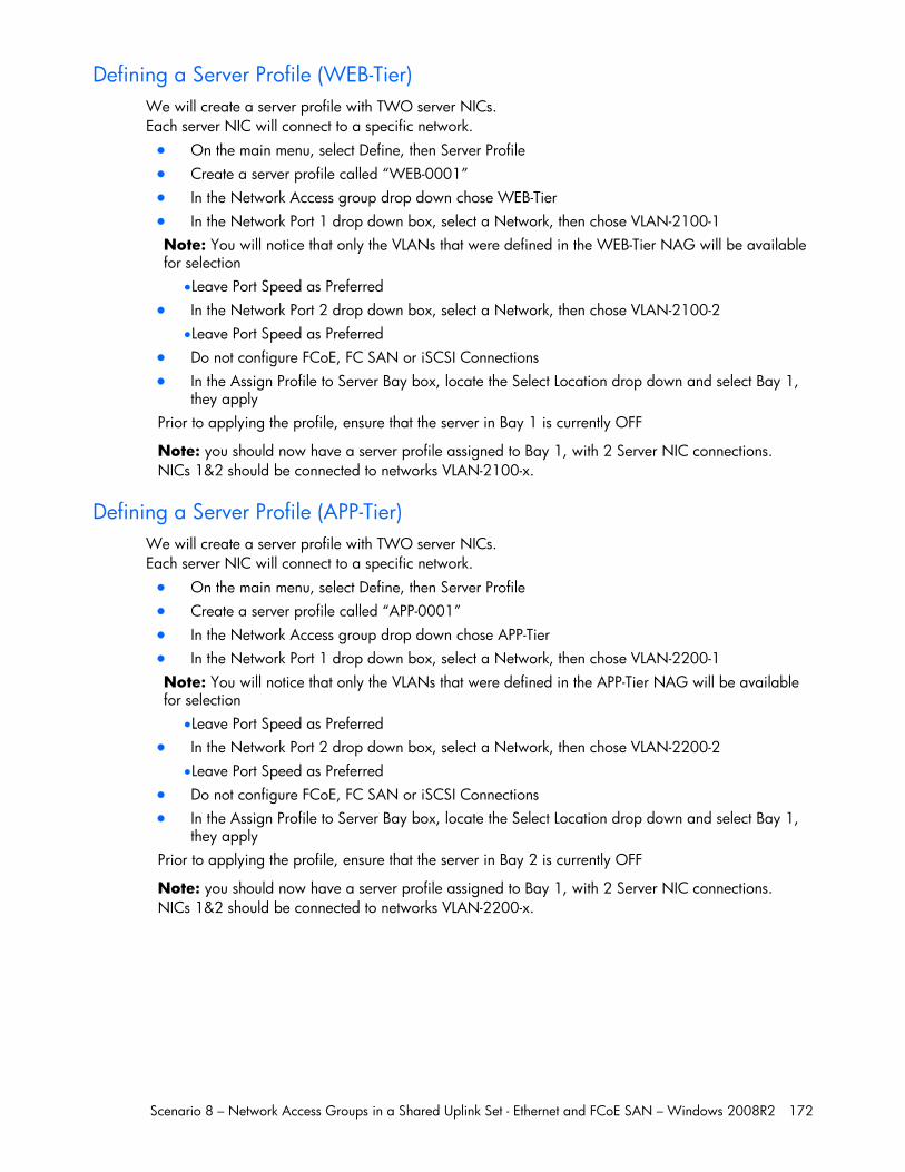
Scenario 8 – Network Access Groups in a Shared Uplink Set - Ethernet and FCoE SAN – Windows 2008R2 172
Defining a Server Profile (WEB-Tier) We will create a server profile with TWO server NICs. Each server NIC will connect to a specific network. On the main menu, select Define, then Server Profile Create a server profile called “WEB-0001” In the Network Access group drop down chose WEB-Tier In the Network Port 1 drop down box, select a Network, then chose VLAN-2100-1
Note: You will notice that only the VLANs that were defined in the WEB-Tier NAG will be available for selection
Leave Port Speed as Preferred In the Network Port 2 drop down box, select a Network, then chose VLAN-2100-2
Leave Port Speed as Preferred Do not configure FCoE, FC SAN or iSCSI Connections In the Assign Profile to Server Bay box, locate the Select Location drop down and select Bay 1,
they apply Prior to applying the profile, ensure that the server in Bay 1 is currently OFF
Note: you should now have a server profile assigned to Bay 1, with 2 Server NIC connections. NICs 1&2 should be connected to networks VLAN-2100-x.
Defining a Server Profile (APP-Tier) We will create a server profile with TWO server NICs. Each server NIC will connect to a specific network. On the main menu, select Define, then Server Profile Create a server profile called “APP-0001” In the Network Access group drop down chose APP-Tier In the Network Port 1 drop down box, select a Network, then chose VLAN-2200-1
Note: You will notice that only the VLANs that were defined in the APP-Tier NAG will be available for selection
Leave Port Speed as Preferred In the Network Port 2 drop down box, select a Network, then chose VLAN-2200-2
Leave Port Speed as Preferred Do not configure FCoE, FC SAN or iSCSI Connections In the Assign Profile to Server Bay box, locate the Select Location drop down and select Bay 1,
they apply Prior to applying the profile, ensure that the server in Bay 2 is currently OFF
Note: you should now have a server profile assigned to Bay 1, with 2 Server NIC connections. NICs 1&2 should be connected to networks VLAN-2200-x.
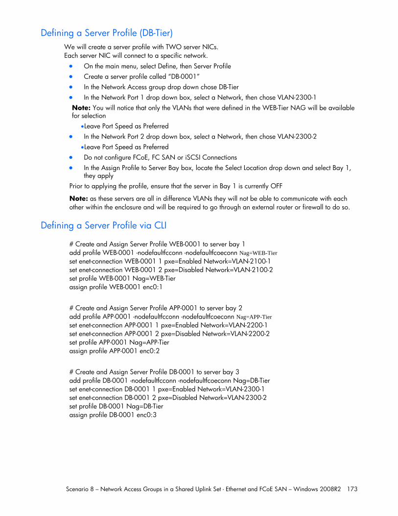
Scenario 8 – Network Access Groups in a Shared Uplink Set - Ethernet and FCoE SAN – Windows 2008R2 173
Defining a Server Profile (DB-Tier) We will create a server profile with TWO server NICs. Each server NIC will connect to a specific network. On the main menu, select Define, then Server Profile Create a server profile called “DB-0001” In the Network Access group drop down chose DB-Tier In the Network Port 1 drop down box, select a Network, then chose VLAN-2300-1
Note: You will notice that only the VLANs that were defined in the WEB-Tier NAG will be available for selection
Leave Port Speed as Preferred In the Network Port 2 drop down box, select a Network, then chose VLAN-2300-2
Leave Port Speed as Preferred Do not configure FCoE, FC SAN or iSCSI Connections In the Assign Profile to Server Bay box, locate the Select Location drop down and select Bay 1,
they apply Prior to applying the profile, ensure that the server in Bay 1 is currently OFF
Note: as these servers are all in difference VLANs they will not be able to communicate with each other within the enclosure and will be required to go through an external router or firewall to do so.
Defining a Server Profile via CLI
# Create and Assign Server Profile WEB-0001 to server bay 1 add profile WEB-0001 -nodefaultfcconn -nodefaultfcoeconn Nag=WEB-Tier set enet-connection WEB-0001 1 pxe=Enabled Network=VLAN-2100-1 set enet-connection WEB-0001 2 pxe=Disabled Network=VLAN-2100-2 set profile WEB-0001 Nag=WEB-Tier assign profile WEB-0001 enc0:1
# Create and Assign Server Profile APP-0001 to server bay 2 add profile APP-0001 -nodefaultfcconn -nodefaultfcoeconn Nag=APP-Tier set enet-connection APP-0001 1 pxe=Enabled Network=VLAN-2200-1 set enet-connection APP-0001 2 pxe=Disabled Network=VLAN-2200-2 set profile APP-0001 Nag=APP-Tier assign profile APP-0001 enc0:2
# Create and Assign Server Profile DB-0001 to server bay 3 add profile DB-0001 -nodefaultfcconn -nodefaultfcoeconn Nag=DB-Tier set enet-connection DB-0001 1 pxe=Enabled Network=VLAN-2300-1 set enet-connection DB-0001 2 pxe=Disabled Network=VLAN-2300-2 set profile DB-0001 Nag=DB-Tier assign profile DB-0001 enc0:3
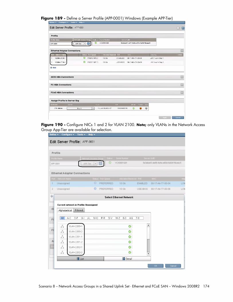
Scenario 8 – Network Access Groups in a Shared Uplink Set - Ethernet and FCoE SAN – Windows 2008R2 174
Figure 189 - Define a Server Profile (APP-0001) Windows (Example APP-Tier)
Figure 190 - Configure NICs 1 and 2 for VLAN 2100. Note; only VLANs in the Network Access Group App-Tier are available for selection.
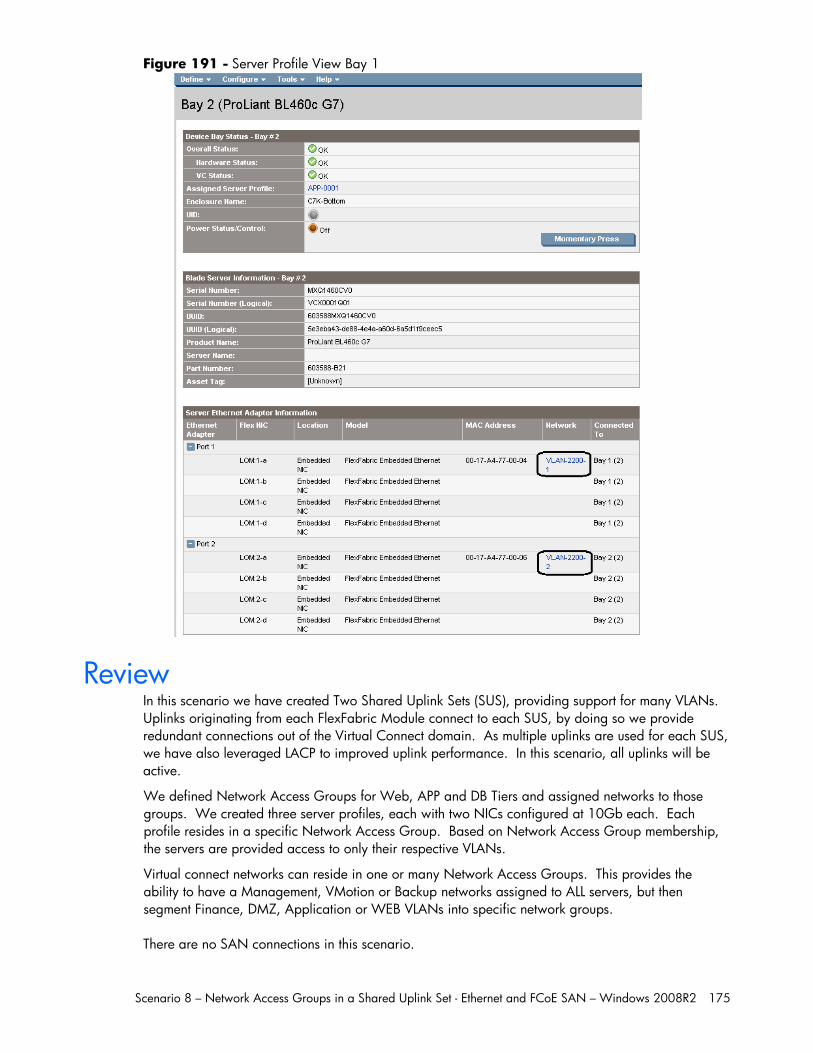
Scenario 8 – Network Access Groups in a Shared Uplink Set - Ethernet and FCoE SAN – Windows 2008R2 175
Figure 191 - Server Profile View Bay 1
Review In this scenario we have created Two Shared Uplink Sets (SUS), providing support for many VLANs. Uplinks originating from each FlexFabric Module connect to each SUS, by doing so we provide redundant connections out of the Virtual Connect domain. As multiple uplinks are used for each SUS, we have also leveraged LACP to improved uplink performance. In this scenario, all uplinks will be active.
We defined Network Access Groups for Web, APP and DB Tiers and assigned networks to those groups. We created three server profiles, each with two NICs configured at 10Gb each. Each profile resides in a specific Network Access Group. Based on Network Access Group membership, the servers are provided access to only their respective VLANs.
Virtual connect networks can reside in one or many Network Access Groups. This provides the ability to have a Management, VMotion or Backup networks assigned to ALL servers, but then segment Finance, DMZ, Application or WEB VLANs into specific network groups. There are no SAN connections in this scenario.

Scenario 8 – Network Access Groups in a Shared Uplink Set - Ethernet and FCoE SAN – Windows 2008R2 176
Results – Windows 2008 R2 Networking Examples We have successfully configured FlexFabric with shared uplink sets and Network Access groups, and no SAN connectivity. We have created three server profiles and assigned them to specific Network Access groups.
Although both Ethernet and Fibre channel connectivity is provided by the CNA adapter used in the G7 servers; each capability (LAN and SAN) is provided by a different component of the adapter, they appear in the server as individual network and SAN adapters.
Figure 192 - Example of Emulex's OneManager Utility (formerly known as HBA Anywhere).
Note: that there are 4 Ethernet personalities and one FCoE personality per port, as configured in the server profile.
The following graphics show a Windows 2008 R2 server with TWO FlexNICs configured at 10Gb. You will also notice that Windows believes there are 8 NICs within this server. However, only TWO NICs are currently configured within FlexFabric, the extra NICs are offline and could be disabled. If we did require SAN connectivity on this server, the FCoE connections would consume two of the connections, leaving 6 NICs available to the OS.
Note: the BL465c G7 and BL685c G7 utilize an NC551i chipset (BE2), whereas the BL460c G7, BL620c G6 and BL680c G7 utilize an NC553i chipset (BE3). Both the BE2 and BE3 chipsets share common drivers and firmware.
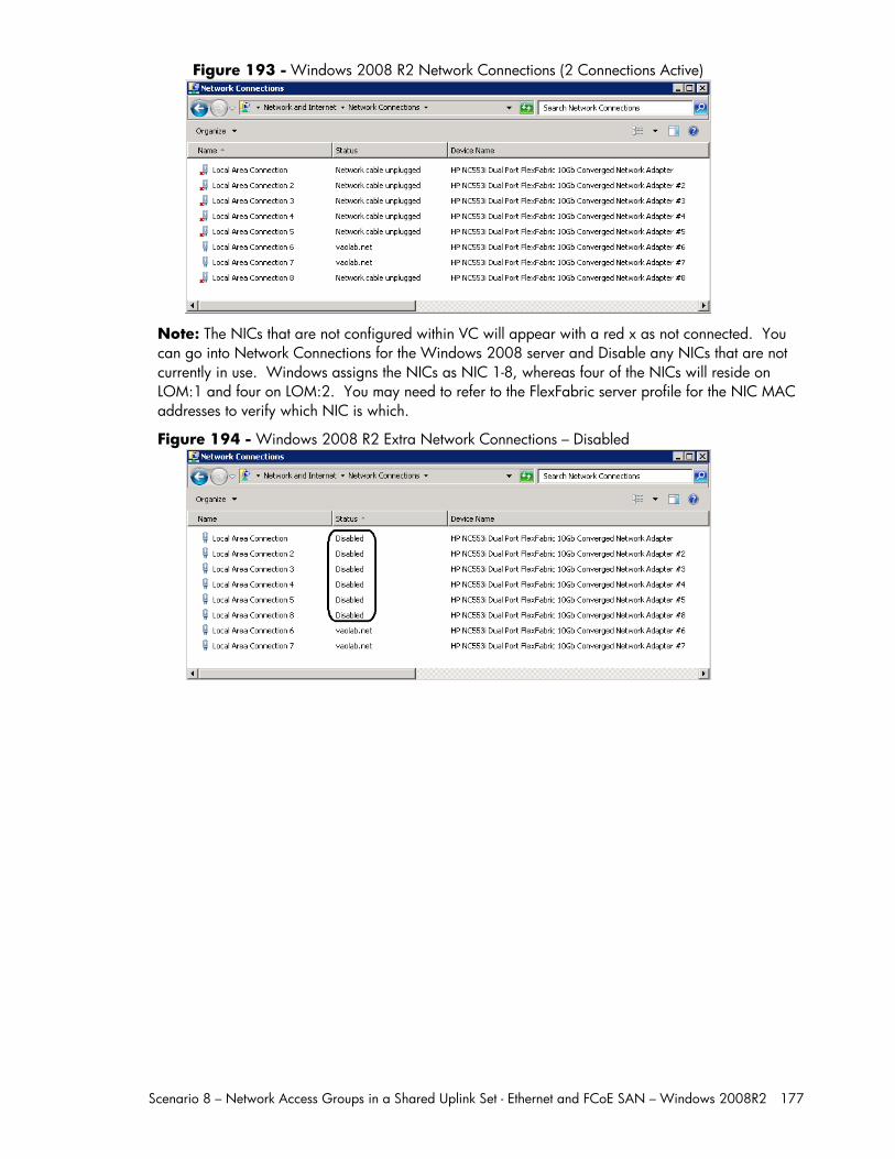
Scenario 8 – Network Access Groups in a Shared Uplink Set - Ethernet and FCoE SAN – Windows 2008R2 177
Figure 193 - Windows 2008 R2 Network Connections (2 Connections Active)
Note: The NICs that are not configured within VC will appear with a red x as not connected. You can go into Network Connections for the Windows 2008 server and Disable any NICs that are not currently in use. Windows assigns the NICs as NIC 1-8, whereas four of the NICs will reside on LOM:1 and four on LOM:2. You may need to refer to the FlexFabric server profile for the NIC MAC addresses to verify which NIC is which.
Figure 194 - Windows 2008 R2 Extra Network Connections – Disabled
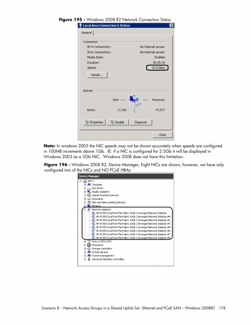
Scenario 8 – Network Access Groups in a Shared Uplink Set - Ethernet and FCoE SAN – Windows 2008R2 178
Figure 195 - Windows 2008 R2 Network Connection Status
Note: In windows 2003 the NIC speeds may not be shown accurately when speeds are configured in 100MB increments above 1Gb. IE: if a NIC is configured for 2.5Gb it will be displayed in Windows 2003 as a 2Gb NIC. Windows 2008 does not have this limitation.
Figure 196 - Windows 2008 R2, Device Manager, Eight NICs are shown, however, we have only configured two of the NICs and NO FCoE HBAs.
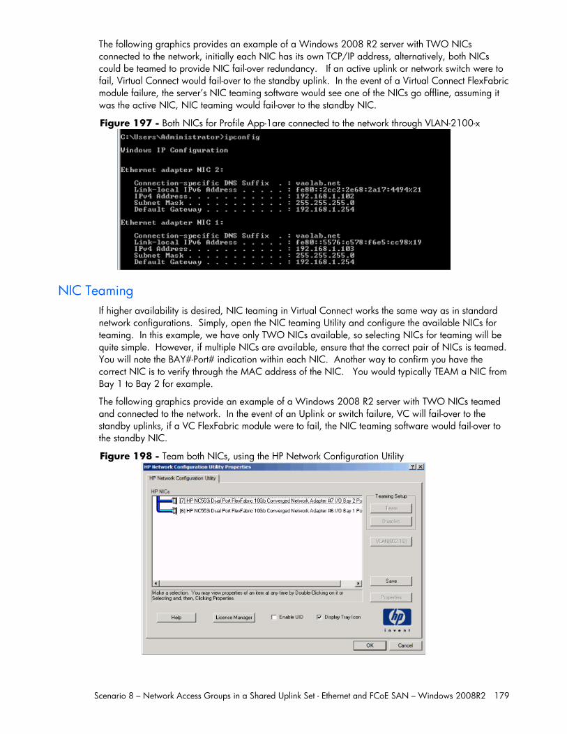
Scenario 8 – Network Access Groups in a Shared Uplink Set - Ethernet and FCoE SAN – Windows 2008R2 179
The following graphics provides an example of a Windows 2008 R2 server with TWO NICs connected to the network, initially each NIC has its own TCP/IP address, alternatively, both NICs could be teamed to provide NIC fail-over redundancy. If an active uplink or network switch were to fail, Virtual Connect would fail-over to the standby uplink. In the event of a Virtual Connect FlexFabric module failure, the server’s NIC teaming software would see one of the NICs go offline, assuming it was the active NIC, NIC teaming would fail-over to the standby NIC.
Figure 197 - Both NICs for Profile App-1are connected to the network through VLAN-2100-x
NIC Teaming If higher availability is desired, NIC teaming in Virtual Connect works the same way as in standard network configurations. Simply, open the NIC teaming Utility and configure the available NICs for teaming. In this example, we have only TWO NICs available, so selecting NICs for teaming will be quite simple. However, if multiple NICs are available, ensure that the correct pair of NICs is teamed. You will note the BAY#-Port# indication within each NIC. Another way to confirm you have the correct NIC is to verify through the MAC address of the NIC. You would typically TEAM a NIC from Bay 1 to Bay 2 for example.
The following graphics provide an example of a Windows 2008 R2 server with TWO NICs teamed and connected to the network. In the event of an Uplink or switch failure, VC will fail-over to the standby uplinks, if a VC FlexFabric module were to fail, the NIC teaming software would fail-over to the standby NIC.
Figure 198 - Team both NICs, using the HP Network Configuration Utility
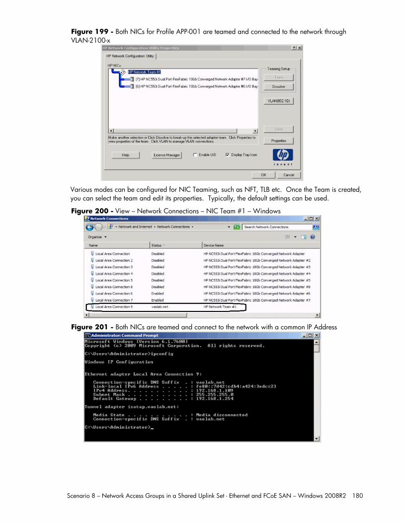
Scenario 8 – Network Access Groups in a Shared Uplink Set - Ethernet and FCoE SAN – Windows 2008R2 180
Figure 199 - Both NICs for Profile APP-001 are teamed and connected to the network through VLAN-2100-x
Various modes can be configured for NIC Teaming, such as NFT, TLB etc. Once the Team is created, you can select the team and edit its properties. Typically, the default settings can be used.
Figure 200 - View – Network Connections – NIC Team #1 – Windows
Figure 201 - Both NICs are teamed and connect to the network with a common IP Address
Scenario 8 – Network Access Groups in a Shared Uplink Set - Ethernet and FCoE SAN – Windows 2008R2 181
Summary We presented a Virtual Connect Network scenario by creating two shared uplink sets (SUS), each SUS is connected with TWO active uplinks, both SUS’ can actively pass traffic.
When VC profile APP-0001 is applied to the server in bay1 and is powered up, it has one NIC connected through FlexFabric module 1 (connected to VLAN-2100-1), the second NIC is connected through FlexFabric module 2 (connected to VLAN-2100-2). These NICs could now be configured as individual NICs with their own IP address or as a pair of TEAMED NICs. Either NIC could be active. As a result, this server could access the network through either NIC or either uplink, depending on which NIC is active at the time. Each NIC is configured for 10Gb of network bandwidth. VLAN access is controlled by Profile membership of a specific Network Access group.
Additional NICs could be added within FlexFabric, by simply powering the server off and adding up to a total of 8 NICs, (or SIX NICs and TWO FCoE connections) speed can then be adjusted accordingly to suit the needs of each NIC. However, any additional NICs would still need to adhere to the Network Access Group policy.
As additional servers are added to the enclosure, simply create additional profiles, or copy existing profiles, configure the NICs for LAN and SAN fabrics as required and apply them to the appropriate server bays and power the server on.
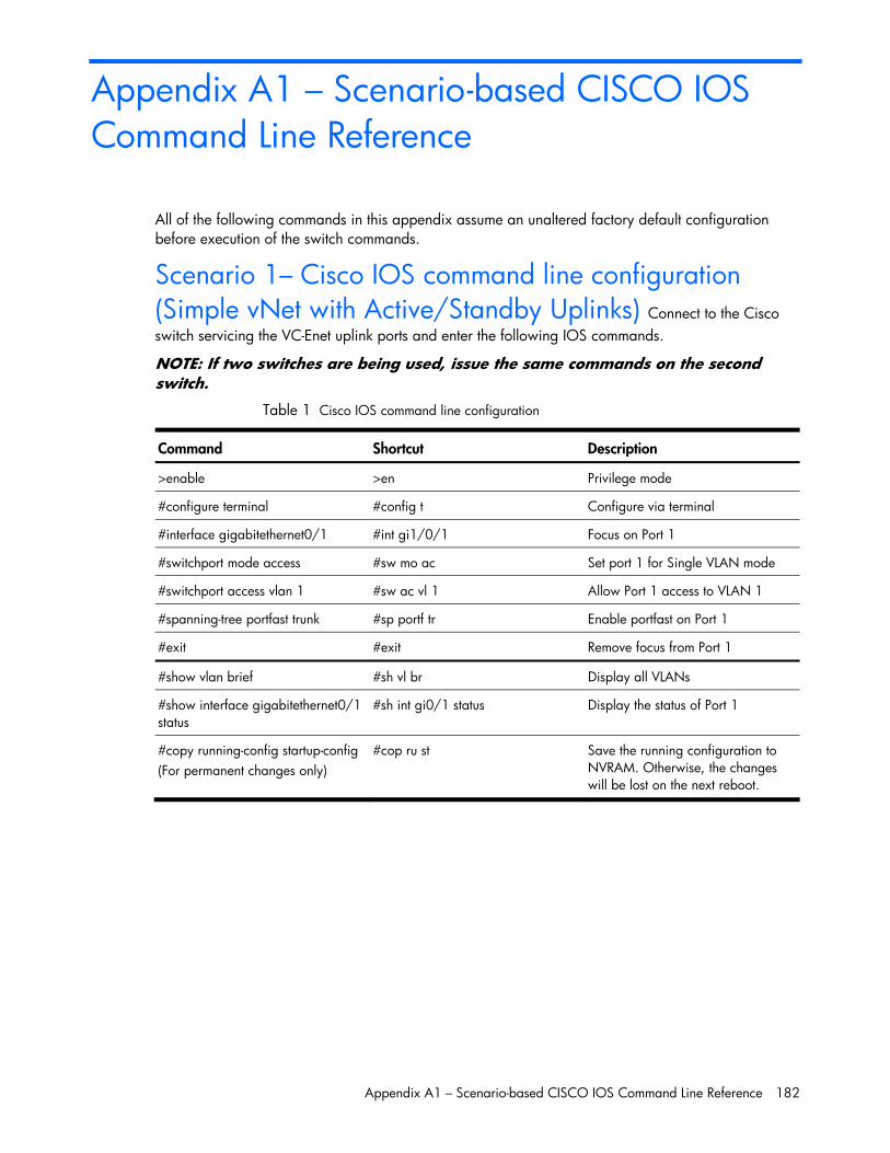
Appendix A1 – Scenario-based CISCO IOS Command Line Reference 182
Appendix A1 – Scenario-based CISCO IOS Command Line Reference
All of the following commands in this appendix assume an unaltered factory default configuration before execution of the switch commands.
Scenario 1– Cisco IOS command line configuration (Simple vNet with Active/Standby Uplinks) Connect to the Cisco switch servicing the VC-Enet uplink ports and enter the following IOS commands.
NOTE: If two switches are being used, issue the same commands on the second switch.
Table 1 Cisco IOS command line configuration
Command Shortcut Description
>enable >en Privilege mode
#configure terminal #config t Configure via terminal
#interface gigabitethernet0/1 #int gi1/0/1 Focus on Port 1
#switchport mode access #sw mo ac Set port 1 for Single VLAN mode
#switchport access vlan 1 #sw ac vl 1 Allow Port 1 access to VLAN 1
#spanning-tree portfast trunk #sp portf tr Enable portfast on Port 1
#exit #exit Remove focus from Port 1
#show vlan brief #sh vl br Display all VLANs
#show interface gigabitethernet0/1 status
#sh int gi0/1 status Display the status of Port 1
#copy running-config startup-config (For permanent changes only)
#cop ru st Save the running configuration to NVRAM. Otherwise, the changes will be lost on the next reboot.
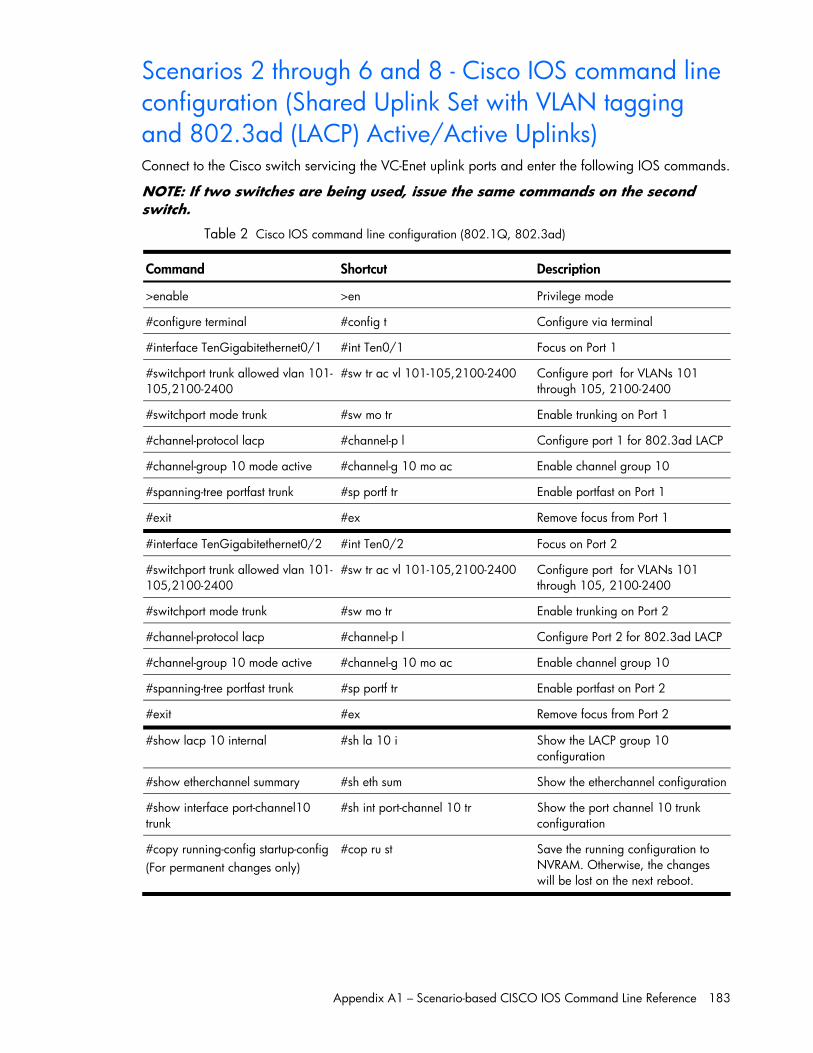
Appendix A1 – Scenario-based CISCO IOS Command Line Reference 183
Scenarios 2 through 6 and 8 - Cisco IOS command line configuration (Shared Uplink Set with VLAN tagging and 802.3ad (LACP) Active/Active Uplinks)
Connect to the Cisco switch servicing the VC-Enet uplink ports and enter the following IOS commands.
NOTE: If two switches are being used, issue the same commands on the second switch.
Table 2 Cisco IOS command line configuration (802.1Q, 802.3ad)
Command Shortcut Description
>enable >en Privilege mode
#configure terminal #config t Configure via terminal
#interface TenGigabitethernet0/1 #int Ten0/1 Focus on Port 1
#switchport trunk allowed vlan 101-105,2100-2400
#sw tr ac vl 101-105,2100-2400 Configure port for VLANs 101 through 105, 2100-2400
#switchport mode trunk #sw mo tr Enable trunking on Port 1
#channel-protocol lacp #channel-p l Configure port 1 for 802.3ad LACP
#channel-group 10 mode active #channel-g 10 mo ac Enable channel group 10
#spanning-tree portfast trunk #sp portf tr Enable portfast on Port 1
#exit #ex Remove focus from Port 1
#interface TenGigabitethernet0/2 #int Ten0/2 Focus on Port 2
#switchport trunk allowed vlan 101-105,2100-2400
#sw tr ac vl 101-105,2100-2400 Configure port for VLANs 101 through 105, 2100-2400
#switchport mode trunk #sw mo tr Enable trunking on Port 2
#channel-protocol lacp #channel-p l Configure Port 2 for 802.3ad LACP
#channel-group 10 mode active #channel-g 10 mo ac Enable channel group 10
#spanning-tree portfast trunk #sp portf tr Enable portfast on Port 2
#exit #ex Remove focus from Port 2
#show lacp 10 internal #sh la 10 i Show the LACP group 10 configuration
#show etherchannel summary #sh eth sum Show the etherchannel configuration
#show interface port-channel10 trunk
#sh int port-channel 10 tr Show the port channel 10 trunk configuration
#copy running-config startup-config (For permanent changes only)
#cop ru st Save the running configuration to NVRAM. Otherwise, the changes will be lost on the next reboot.
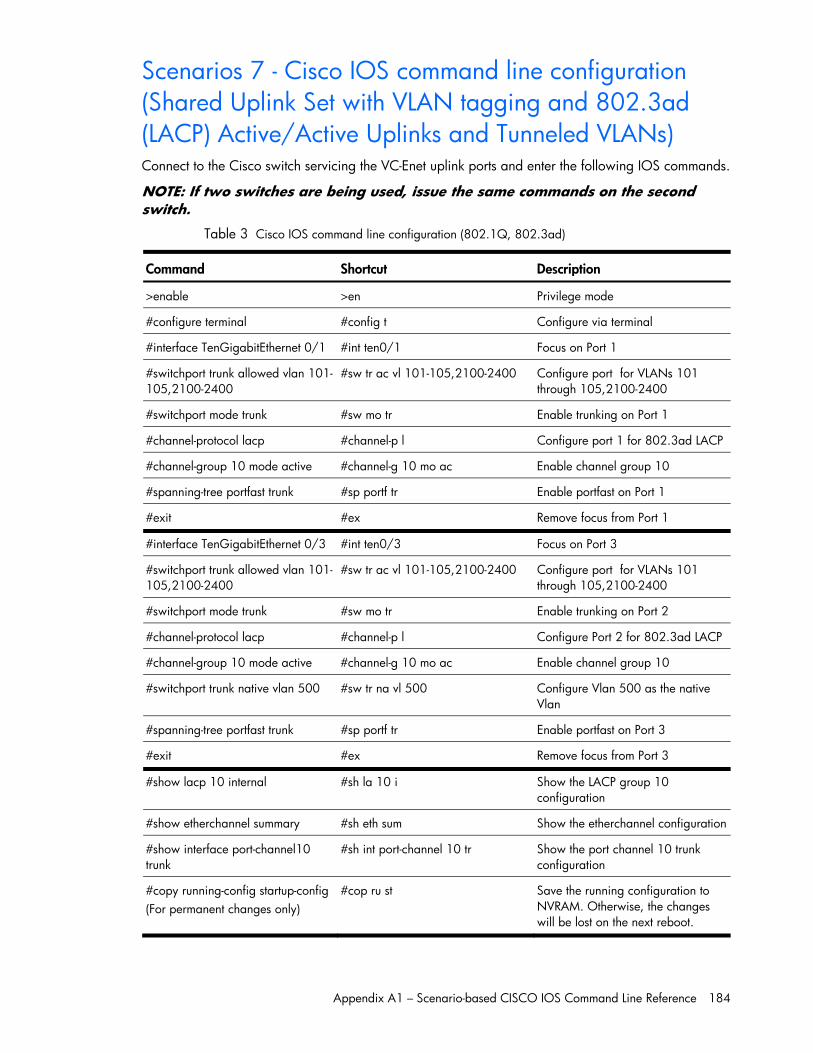
Appendix A1 – Scenario-based CISCO IOS Command Line Reference 184
Scenarios 7 - Cisco IOS command line configuration (Shared Uplink Set with VLAN tagging and 802.3ad (LACP) Active/Active Uplinks and Tunneled VLANs) Connect to the Cisco switch servicing the VC-Enet uplink ports and enter the following IOS commands.
NOTE: If two switches are being used, issue the same commands on the second switch.
Table 3 Cisco IOS command line configuration (802.1Q, 802.3ad)
Command Shortcut Description
>enable >en Privilege mode
#configure terminal #config t Configure via terminal
#interface TenGigabitEthernet 0/1 #int ten0/1 Focus on Port 1
#switchport trunk allowed vlan 101-105,2100-2400
#sw tr ac vl 101-105,2100-2400 Configure port for VLANs 101 through 105,2100-2400
#switchport mode trunk #sw mo tr Enable trunking on Port 1
#channel-protocol lacp #channel-p l Configure port 1 for 802.3ad LACP
#channel-group 10 mode active #channel-g 10 mo ac Enable channel group 10
#spanning-tree portfast trunk #sp portf tr Enable portfast on Port 1
#exit #ex Remove focus from Port 1
#interface TenGigabitEthernet 0/3 #int ten0/3 Focus on Port 3
#switchport trunk allowed vlan 101-105,2100-2400
#sw tr ac vl 101-105,2100-2400 Configure port for VLANs 101 through 105,2100-2400
#switchport mode trunk #sw mo tr Enable trunking on Port 2
#channel-protocol lacp #channel-p l Configure Port 2 for 802.3ad LACP
#channel-group 10 mode active #channel-g 10 mo ac Enable channel group 10
#switchport trunk native vlan 500 #sw tr na vl 500 Configure Vlan 500 as the native Vlan
#spanning-tree portfast trunk #sp portf tr Enable portfast on Port 3
#exit #ex Remove focus from Port 3
#show lacp 10 internal #sh la 10 i Show the LACP group 10 configuration
#show etherchannel summary #sh eth sum Show the etherchannel configuration
#show interface port-channel10 trunk
#sh int port-channel 10 tr Show the port channel 10 trunk configuration
#copy running-config startup-config (For permanent changes only)
#cop ru st Save the running configuration to NVRAM. Otherwise, the changes will be lost on the next reboot.
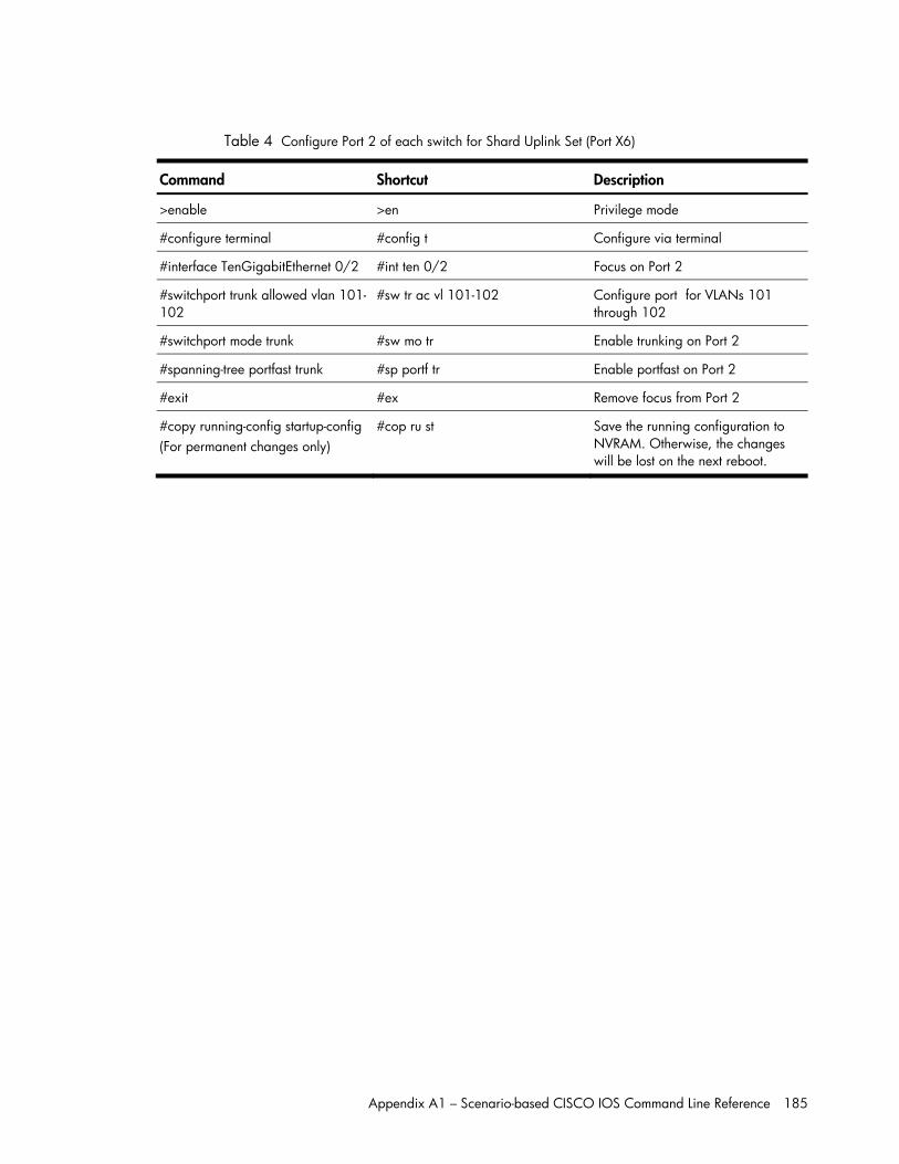
Appendix A1 – Scenario-based CISCO IOS Command Line Reference 185
Table 4 Configure Port 2 of each switch for Shard Uplink Set (Port X6)
Command Shortcut Description
>enable >en Privilege mode
#configure terminal #config t Configure via terminal
#interface TenGigabitEthernet 0/2 #int ten 0/2 Focus on Port 2
#switchport trunk allowed vlan 101-102
#sw tr ac vl 101-102 Configure port for VLANs 101 through 102
#switchport mode trunk #sw mo tr Enable trunking on Port 2
#spanning-tree portfast trunk #sp portf tr Enable portfast on Port 2
#exit #ex Remove focus from Port 2
#copy running-config startup-config (For permanent changes only)
#cop ru st Save the running configuration to NVRAM. Otherwise, the changes will be lost on the next reboot.
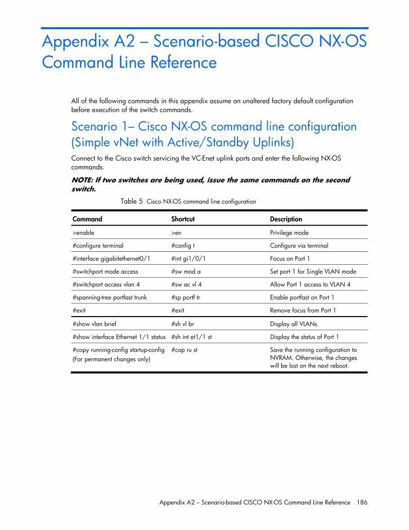
Appendix A2 – Scenario-based CISCO NX-OS Command Line Reference 186
Appendix A2 – Scenario-based CISCO NX-OS Command Line Reference
All of the following commands in this appendix assume an unaltered factory default configuration before execution of the switch commands.
Scenario 1– Cisco NX-OS command line configuration (Simple vNet with Active/Standby Uplinks) Connect to the Cisco switch servicing the VC-Enet uplink ports and enter the following NX-OS commands.
NOTE: If two switches are being used, issue the same commands on the second switch.
Table 5 Cisco NX-OS command line configuration
Command Shortcut Description
>enable >en Privilege mode
#configure terminal #config t Configure via terminal
#interface gigabitethernet0/1 #int gi1/0/1 Focus on Port 1
#switchport mode access #sw mod a Set port 1 for Single VLAN mode
#switchport access vlan 4 #sw ac vl 4 Allow Port 1 access to VLAN 4
#spanning-tree portfast trunk #sp portf tr Enable portfast on Port 1
#exit #exit Remove focus from Port 1
#show vlan brief #sh vl br Display all VLANs
#show interface Ethernet 1/1 status #sh int et1/1 st Display the status of Port 1
#copy running-config startup-config (For permanent changes only)
#cop ru st Save the running configuration to NVRAM. Otherwise, the changes will be lost on the next reboot.
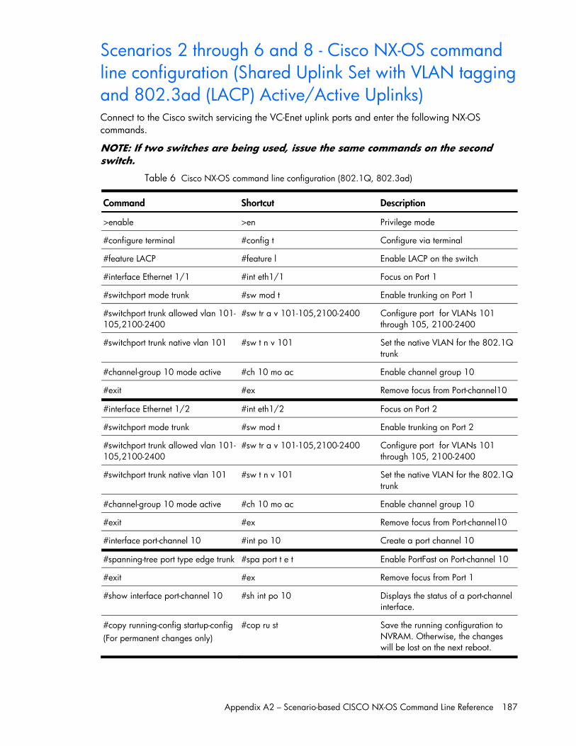
Appendix A2 – Scenario-based CISCO NX-OS Command Line Reference 187
Scenarios 2 through 6 and 8 - Cisco NX-OS command line configuration (Shared Uplink Set with VLAN tagging and 802.3ad (LACP) Active/Active Uplinks)
Connect to the Cisco switch servicing the VC-Enet uplink ports and enter the following NX-OS commands.
NOTE: If two switches are being used, issue the same commands on the second switch.
Table 6 Cisco NX-OS command line configuration (802.1Q, 802.3ad)
Command Shortcut Description
>enable >en Privilege mode
#configure terminal #config t Configure via terminal
#feature LACP #feature l Enable LACP on the switch
#interface Ethernet 1/1 #int eth1/1 Focus on Port 1
#switchport mode trunk #sw mod t Enable trunking on Port 1
#switchport trunk allowed vlan 101-105,2100-2400
#sw tr a v 101-105,2100-2400 Configure port for VLANs 101 through 105, 2100-2400
#switchport trunk native vlan 101 #sw t n v 101 Set the native VLAN for the 802.1Q trunk
#channel-group 10 mode active #ch 10 mo ac Enable channel group 10
#exit #ex Remove focus from Port-channel10
#interface Ethernet 1/2 #int eth1/2 Focus on Port 2
#switchport mode trunk #sw mod t Enable trunking on Port 2
#switchport trunk allowed vlan 101-105,2100-2400
#sw tr a v 101-105,2100-2400 Configure port for VLANs 101 through 105, 2100-2400
#switchport trunk native vlan 101 #sw t n v 101 Set the native VLAN for the 802.1Q trunk
#channel-group 10 mode active #ch 10 mo ac Enable channel group 10
#exit #ex Remove focus from Port-channel10
#interface port-channel 10 #int po 10 Create a port channel 10
#spanning-tree port type edge trunk #spa port t e t Enable PortFast on Port-channel 10
#exit #ex Remove focus from Port 1
#show interface port-channel 10 #sh int po 10 Displays the status of a port-channel interface.
#copy running-config startup-config (For permanent changes only)
#cop ru st Save the running configuration to NVRAM. Otherwise, the changes will be lost on the next reboot.
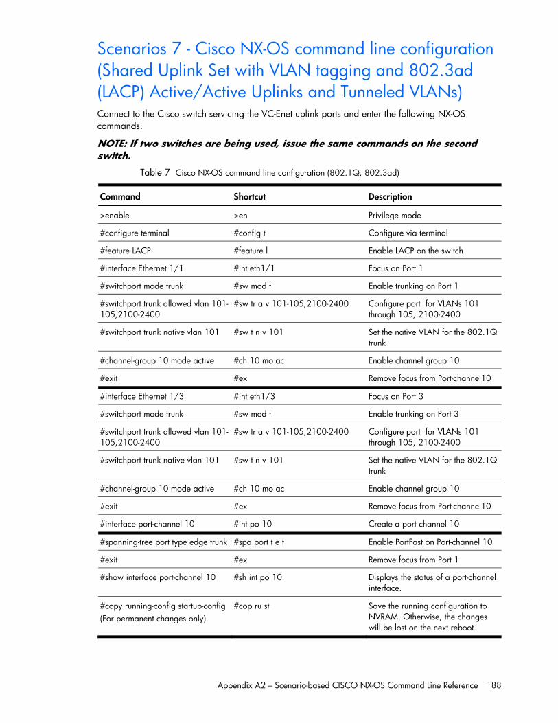
Appendix A2 – Scenario-based CISCO NX-OS Command Line Reference 188
Scenarios 7 - Cisco NX-OS command line configuration (Shared Uplink Set with VLAN tagging and 802.3ad (LACP) Active/Active Uplinks and Tunneled VLANs) Connect to the Cisco switch servicing the VC-Enet uplink ports and enter the following NX-OS commands.
NOTE: If two switches are being used, issue the same commands on the second switch.
Table 7 Cisco NX-OS command line configuration (802.1Q, 802.3ad)
Command Shortcut Description
>enable >en Privilege mode
#configure terminal #config t Configure via terminal
#feature LACP #feature l Enable LACP on the switch
#interface Ethernet 1/1 #int eth1/1 Focus on Port 1
#switchport mode trunk #sw mod t Enable trunking on Port 1
#switchport trunk allowed vlan 101-105,2100-2400
#sw tr a v 101-105,2100-2400 Configure port for VLANs 101 through 105, 2100-2400
#switchport trunk native vlan 101 #sw t n v 101 Set the native VLAN for the 802.1Q trunk
#channel-group 10 mode active #ch 10 mo ac Enable channel group 10
#exit #ex Remove focus from Port-channel10
#interface Ethernet 1/3 #int eth1/3 Focus on Port 3
#switchport mode trunk #sw mod t Enable trunking on Port 3
#switchport trunk allowed vlan 101-105,2100-2400
#sw tr a v 101-105,2100-2400 Configure port for VLANs 101 through 105, 2100-2400
#switchport trunk native vlan 101 #sw t n v 101 Set the native VLAN for the 802.1Q trunk
#channel-group 10 mode active #ch 10 mo ac Enable channel group 10
#exit #ex Remove focus from Port-channel10
#interface port-channel 10 #int po 10 Create a port channel 10
#spanning-tree port type edge trunk #spa port t e t Enable PortFast on Port-channel 10
#exit #ex Remove focus from Port 1
#show interface port-channel 10 #sh int po 10 Displays the status of a port-channel interface.
#copy running-config startup-config (For permanent changes only)
#cop ru st Save the running configuration to NVRAM. Otherwise, the changes will be lost on the next reboot.
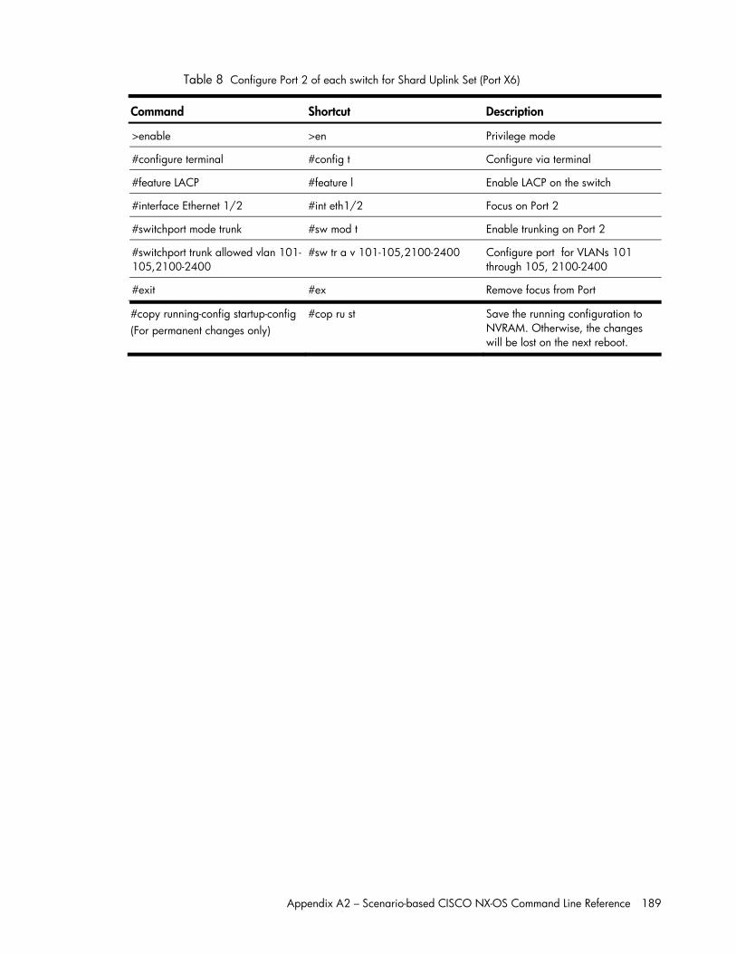
Appendix A2 – Scenario-based CISCO NX-OS Command Line Reference 189
Table 8 Configure Port 2 of each switch for Shard Uplink Set (Port X6)
Command Shortcut Description
>enable >en Privilege mode
#configure terminal #config t Configure via terminal
#feature LACP #feature l Enable LACP on the switch
#interface Ethernet 1/2 #int eth1/2 Focus on Port 2
#switchport mode trunk #sw mod t Enable trunking on Port 2
#switchport trunk allowed vlan 101-105,2100-2400
#sw tr a v 101-105,2100-2400 Configure port for VLANs 101 through 105, 2100-2400
#exit #ex Remove focus from Port
#copy running-config startup-config (For permanent changes only)
#cop ru st Save the running configuration to NVRAM. Otherwise, the changes will be lost on the next reboot.
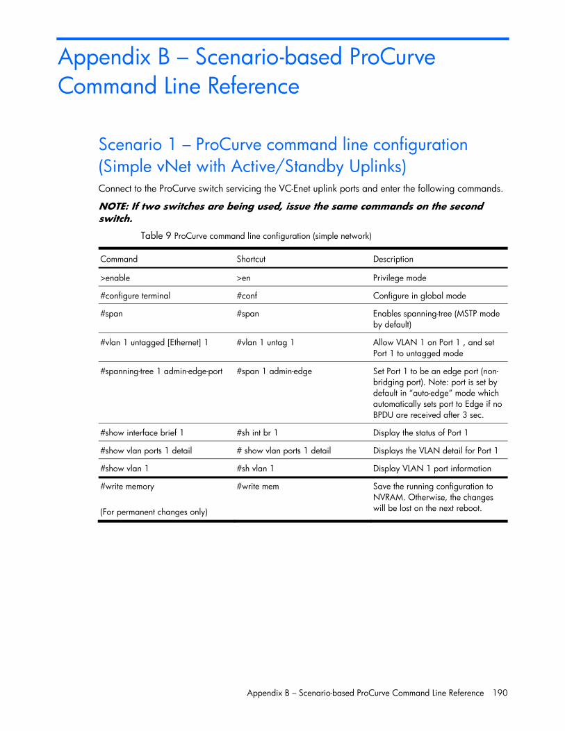
Appendix B – Scenario-based ProCurve Command Line Reference 190
Appendix B – Scenario-based ProCurve Command Line Reference
Scenario 1 – ProCurve command line configuration (Simple vNet with Active/Standby Uplinks) Connect to the ProCurve switch servicing the VC-Enet uplink ports and enter the following commands.
NOTE: If two switches are being used, issue the same commands on the second switch.
Table 9 ProCurve command line configuration (simple network)
Command Shortcut Description
>enable >en Privilege mode
#configure terminal #conf Configure in global mode
#span #span Enables spanning-tree (MSTP mode by default)
#vlan 1 untagged [Ethernet] 1 #vlan 1 untag 1 Allow VLAN 1 on Port 1 , and set Port 1 to untagged mode
#spanning-tree 1 admin-edge-port #span 1 admin-edge Set Port 1 to be an edge port (non-bridging port). Note: port is set by default in “auto-edge” mode which automatically sets port to Edge if no BPDU are received after 3 sec.
#show interface brief 1 #sh int br 1 Display the status of Port 1
#show vlan ports 1 detail # show vlan ports 1 detail Displays the VLAN detail for Port 1
#show vlan 1 #sh vlan 1 Display VLAN 1 port information
#write memory (For permanent changes only)
#write mem Save the running configuration to NVRAM. Otherwise, the changes will be lost on the next reboot.
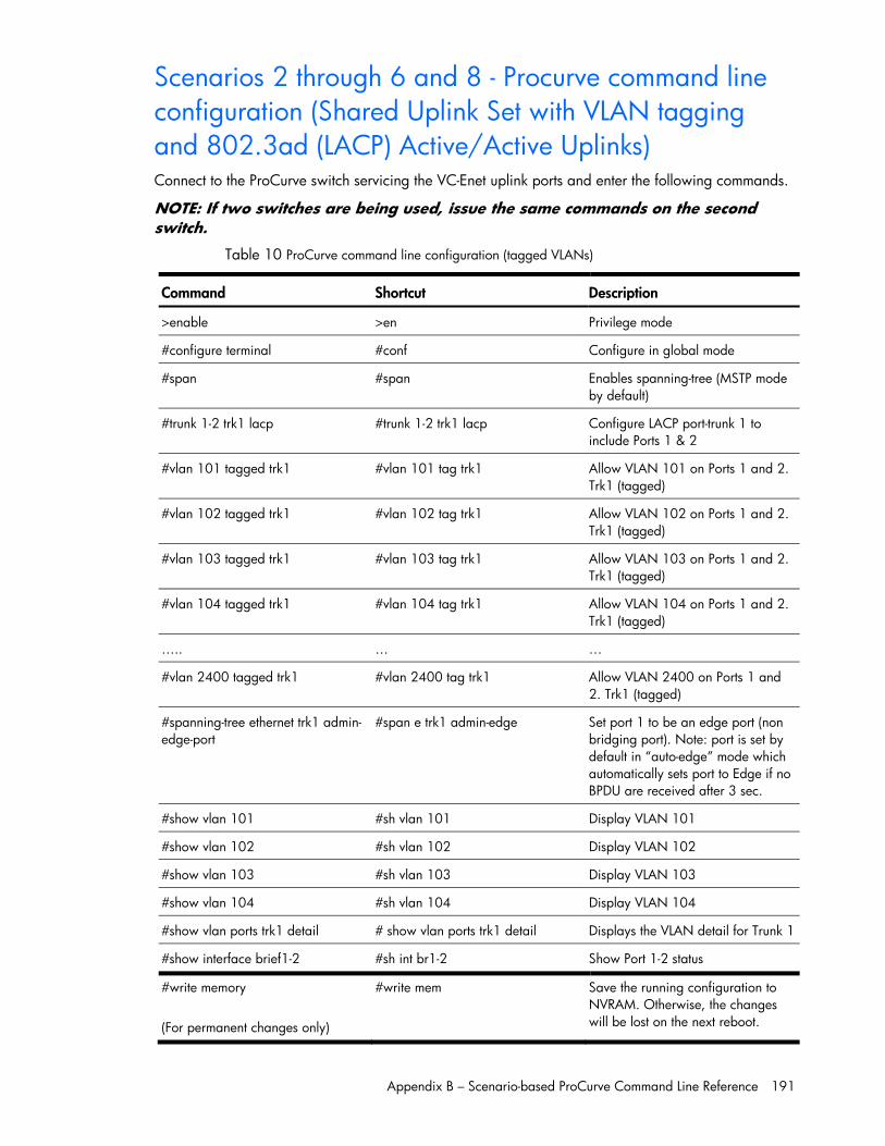
Appendix B – Scenario-based ProCurve Command Line Reference 191
Scenarios 2 through 6 and 8 - Procurve command line configuration (Shared Uplink Set with VLAN tagging and 802.3ad (LACP) Active/Active Uplinks)
Connect to the ProCurve switch servicing the VC-Enet uplink ports and enter the following commands.
NOTE: If two switches are being used, issue the same commands on the second switch.
Table 10 ProCurve command line configuration (tagged VLANs)
Command Shortcut Description
>enable >en Privilege mode
#configure terminal #conf Configure in global mode
#span #span Enables spanning-tree (MSTP mode by default)
#trunk 1-2 trk1 lacp #trunk 1-2 trk1 lacp Configure LACP port-trunk 1 to include Ports 1 & 2
#vlan 101 tagged trk1 #vlan 101 tag trk1 Allow VLAN 101 on Ports 1 and 2. Trk1 (tagged)
#vlan 102 tagged trk1 #vlan 102 tag trk1 Allow VLAN 102 on Ports 1 and 2. Trk1 (tagged)
#vlan 103 tagged trk1 #vlan 103 tag trk1 Allow VLAN 103 on Ports 1 and 2. Trk1 (tagged)
#vlan 104 tagged trk1 #vlan 104 tag trk1 Allow VLAN 104 on Ports 1 and 2. Trk1 (tagged)
….. … …
#vlan 2400 tagged trk1 #vlan 2400 tag trk1 Allow VLAN 2400 on Ports 1 and 2. Trk1 (tagged)
#spanning-tree ethernet trk1 admin-edge-port
#span e trk1 admin-edge Set port 1 to be an edge port (non bridging port). Note: port is set by default in “auto-edge” mode which automatically sets port to Edge if no BPDU are received after 3 sec.
#show vlan 101 #sh vlan 101 Display VLAN 101
#show vlan 102 #sh vlan 102 Display VLAN 102
#show vlan 103 #sh vlan 103 Display VLAN 103
#show vlan 104 #sh vlan 104 Display VLAN 104
#show vlan ports trk1 detail # show vlan ports trk1 detail Displays the VLAN detail for Trunk 1
#show interface brief1-2 #sh int br1-2 Show Port 1-2 status
#write memory (For permanent changes only)
#write mem Save the running configuration to NVRAM. Otherwise, the changes will be lost on the next reboot.
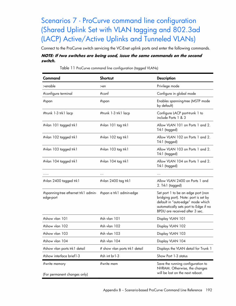
Appendix B – Scenario-based ProCurve Command Line Reference 192
Scenarios 7 - ProCurve command line configuration (Shared Uplink Set with VLAN tagging and 802.3ad (LACP) Active/Active Uplinks and Tunneled VLANs) Connect to the ProCurve switch servicing the VC-Enet uplink ports and enter the following commands.
NOTE: If two switches are being used, issue the same commands on the second switch.
Table 11 ProCurve command line configuration (tagged VLANs)
Command Shortcut Description
>enable >en Privilege mode
#configure terminal #conf Configure in global mode
#span #span Enables spanning-tree (MSTP mode by default)
#trunk 1-3 trk1 lacp #trunk 1-3 trk1 lacp Configure LACP port-trunk 1 to include Ports 1 & 3
#vlan 101 tagged trk1 #vlan 101 tag trk1 Allow VLAN 101 on Ports 1 and 2. Trk1 (tagged)
#vlan 102 tagged trk1 #vlan 102 tag trk1 Allow VLAN 102 on Ports 1 and 2. Trk1 (tagged)
#vlan 103 tagged trk1 #vlan 103 tag trk1 Allow VLAN 103 on Ports 1 and 2. Trk1 (tagged)
#vlan 104 tagged trk1 #vlan 104 tag trk1 Allow VLAN 104 on Ports 1 and 2. Trk1 (tagged)
….. … …
#vlan 2400 tagged trk1 #vlan 2400 tag trk1 Allow VLAN 2400 on Ports 1 and 2. Trk1 (tagged)
#spanning-tree ethernet trk1 admin-edge-port
#span e trk1 admin-edge Set port 1 to be an edge port (non bridging port). Note: port is set by default in “auto-edge” mode which automatically sets port to Edge if no BPDU are received after 3 sec.
#show vlan 101 #sh vlan 101 Display VLAN 101
#show vlan 102 #sh vlan 102 Display VLAN 102
#show vlan 103 #sh vlan 103 Display VLAN 103
#show vlan 104 #sh vlan 104 Display VLAN 104
#show vlan ports trk1 detail # show vlan ports trk1 detail Displays the VLAN detail for Trunk 1
#show interface brief1-3 #sh int br1-3 Show Port 1-3 status
#write memory (For permanent changes only)
#write mem Save the running configuration to NVRAM. Otherwise, the changes will be lost on the next reboot.
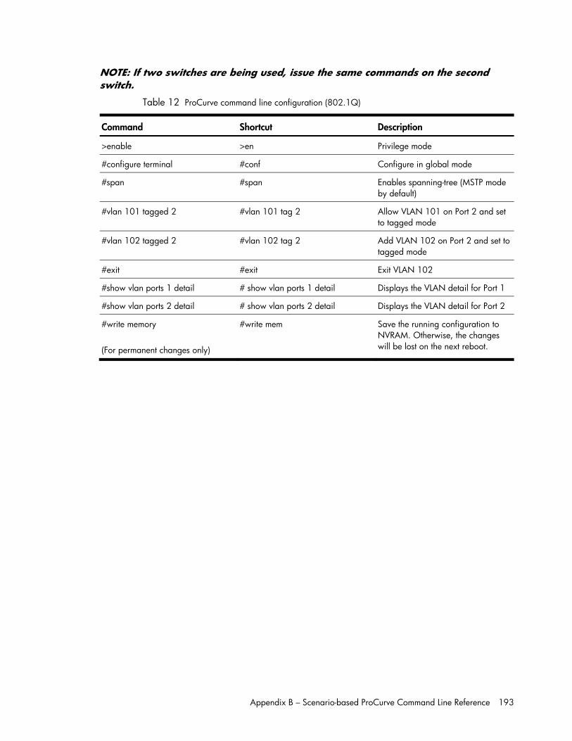
Appendix B – Scenario-based ProCurve Command Line Reference 193
NOTE: If two switches are being used, issue the same commands on the second switch.
Table 12 ProCurve command line configuration (802.1Q)
Command Shortcut Description
>enable >en Privilege mode
#configure terminal #conf Configure in global mode
#span #span Enables spanning-tree (MSTP mode by default)
#vlan 101 tagged 2 #vlan 101 tag 2 Allow VLAN 101 on Port 2 and set to tagged mode
#vlan 102 tagged 2 #vlan 102 tag 2 Add VLAN 102 on Port 2 and set to tagged mode
#exit #exit Exit VLAN 102
#show vlan ports 1 detail # show vlan ports 1 detail Displays the VLAN detail for Port 1
#show vlan ports 2 detail # show vlan ports 2 detail Displays the VLAN detail for Port 2
#write memory (For permanent changes only)
#write mem Save the running configuration to NVRAM. Otherwise, the changes will be lost on the next reboot.
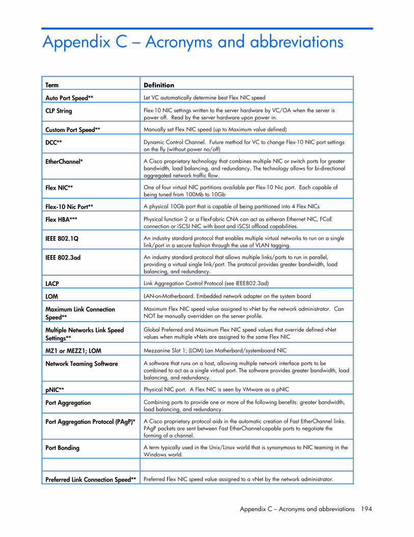
Appendix C – Acronyms and abbreviations 194
Appendix C – Acronyms and abbreviations
Term Definition
Auto Port Speed** Let VC automatically determine best Flex NIC speed
CLP String Flex-10 NIC settings written to the server hardware by VC/OA when the server is power off. Read by the server hardware upon power in.
Custom Port Speed** Manually set Flex NIC speed (up to Maximum value defined)
DCC** Dynamic Control Channel. Future method for VC to change Flex-10 NIC port settings on the fly (without power no/off)
EtherChannel* A Cisco proprietary technology that combines multiple NIC or switch ports for greater bandwidth, load balancing, and redundancy. The technology allows for bi-directional aggregated network traffic flow.
Flex NIC** One of four virtual NIC partitions available per Flex-10 Nic port. Each capable of being tuned from 100Mb to 10Gb
Flex-10 Nic Port** A physical 10Gb port that is capable of being partitioned into 4 Flex NICs
Flex HBA*** Physical function 2 or a FlexFabric CNA can act as eitheran Ethernet NIC, FCoE connection or iSCSI NIC with boot and iSCSI offload capabilities.
IEEE 802.1Q An industry standard protocol that enables multiple virtual networks to run on a single link/port in a secure fashion through the use of VLAN tagging.
IEEE 802.3ad An industry standard protocol that allows multiple links/ports to run in parallel, providing a virtual single link/port. The protocol provides greater bandwidth, load balancing, and redundancy.
LACP Link Aggregation Control Protocol (see IEEE802.3ad)
LOM LAN-on-Motherboard. Embedded network adapter on the system board
Maximum Link Connection Speed**
Maximum Flex NIC speed value assigned to vNet by the network administrator. Can NOT be manually overridden on the server profile.
Multiple Networks Link Speed Settings**
Global Preferred and Maximum Flex NIC speed values that override defined vNet values when multiple vNets are assigned to the same Flex NIC
MZ1 or MEZZ1; LOM Mezzanine Slot 1; (LOM) Lan Motherbard/systemboard NIC
Network Teaming Software A software that runs on a host, allowing multiple network interface ports to be combined to act as a single virtual port. The software provides greater bandwidth, load balancing, and redundancy.
pNIC** Physical NIC port. A Flex NIC is seen by VMware as a pNIC
Port Aggregation Combining ports to provide one or more of the following benefits: greater bandwidth, load balancing, and redundancy.
Port Aggregation Protocol (PAgP)* A Cisco proprietary protocol aids in the automatic creation of Fast EtherChannel links. PAgP packets are sent between Fast EtherChannel-capable ports to negotiate the forming of a channel.
Port Bonding A term typically used in the Unix/Linux world that is synonymous to NIC teaming in the Windows world.
Preferred Link Connection Speed** Preferred Flex NIC speed value assigned to a vNet by the network administrator.
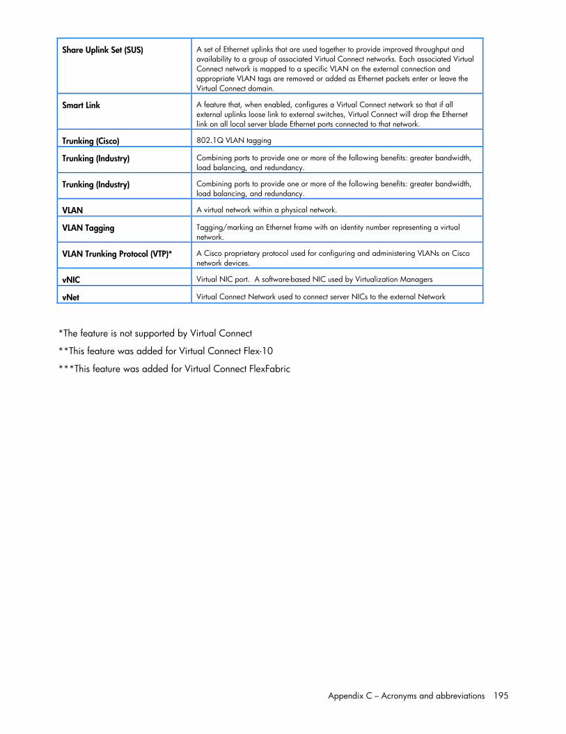
Appendix C – Acronyms and abbreviations 195
Share Uplink Set (SUS) A set of Ethernet uplinks that are used together to provide improved throughput and availability to a group of associated Virtual Connect networks. Each associated Virtual Connect network is mapped to a specific VLAN on the external connection and appropriate VLAN tags are removed or added as Ethernet packets enter or leave the Virtual Connect domain.
Smart Link A feature that, when enabled, configures a Virtual Connect network so that if all external uplinks loose link to external switches, Virtual Connect will drop the Ethernet link on all local server blade Ethernet ports connected to that network.
Trunking (Cisco) 802.1Q VLAN tagging
Trunking (Industry) Combining ports to provide one or more of the following benefits: greater bandwidth, load balancing, and redundancy.
Trunking (Industry) Combining ports to provide one or more of the following benefits: greater bandwidth, load balancing, and redundancy.
VLAN A virtual network within a physical network.
VLAN Tagging Tagging/marking an Ethernet frame with an identity number representing a virtual network.
VLAN Trunking Protocol (VTP)* A Cisco proprietary protocol used for configuring and administering VLANs on Cisco network devices.
vNIC Virtual NIC port. A software-based NIC used by Virtualization Managers
vNet Virtual Connect Network used to connect server NICs to the external Network
*The feature is not supported by Virtual Connect
**This feature was added for Virtual Connect Flex-10
***This feature was added for Virtual Connect FlexFabric
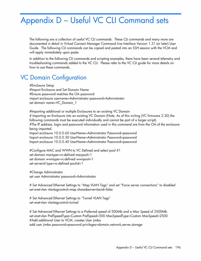
Appendix D – Useful VC CLI Command sets 196
Appendix D – Useful VC CLI Command sets
The following are a collection of useful VC CLI commands. These CLI commands and many more are documented in detail in Virtual Connect Manager Command Line Interface Version 1.31 (or later) User Guide. The following CLI commands can be copied and pasted into an SSH session with the VCM and will apply immediately upon paste.
In addition to the following CLI commands and scripting examples, there have been several telemetry and troubleshooting commands added to the VC CLI. Please refer to the VC CLI guide for more details on how to sue these commands.
VC Domain Configuration #Enclosure Setup #Import Enclosure and Set Domain Name #Ensure password matches the OA password import enclosure username=Administrator password=Administrator set domain name=VC_Domain_1 #Importing additional or multiple Enclosures to an existing VC Domain # Importing an Enclosure into an existing VC Domain (Note: As of this writing (VC firmware 2.30) the following commands must be executed individually and cannot be part of a larger script). #The IP address, login and password information used in this command are from the OA of the enclosure being imported. Import enclosure 10.0.0.60 UserName=Administrator Password=password Import enclosure 10.0.0.30 UserName=Administrator Password=password Import enclosure 10.0.0.40 UserName=Administrator Password=password #Configure MAC and WWN to VC Defined and select pool #1 set domain mactype=vc-defined macpool=1 set domain wwntype=vc-defined wwnpool=1 set serverid type=vc-defined poolid=1 #Change Administrator set user Administrator password=Administrator # Set Advanced Ethernet Settings to "Map VLAN Tags" and set "Force server connections" to disabled set enet-vlan vlantagcontrol=map sharedservervlanid=false # Set Advanced Ethernet Settings to "Tunnel VLAN Tags" set enet-vlan vlantagcontrol=tunnel # Set Advanced Ethernet Settings to a Preferred speed of 500Mb and a Max Speed of 2500Mb set enet-vlan PrefSpeedType=Custom PrefSpeed=500 MaxSpeedType=Custom MaxSpeed=2500 #Add additional User to VCM, creates User jimbo add user jimbo password=password privileges=domain,network,server,storage
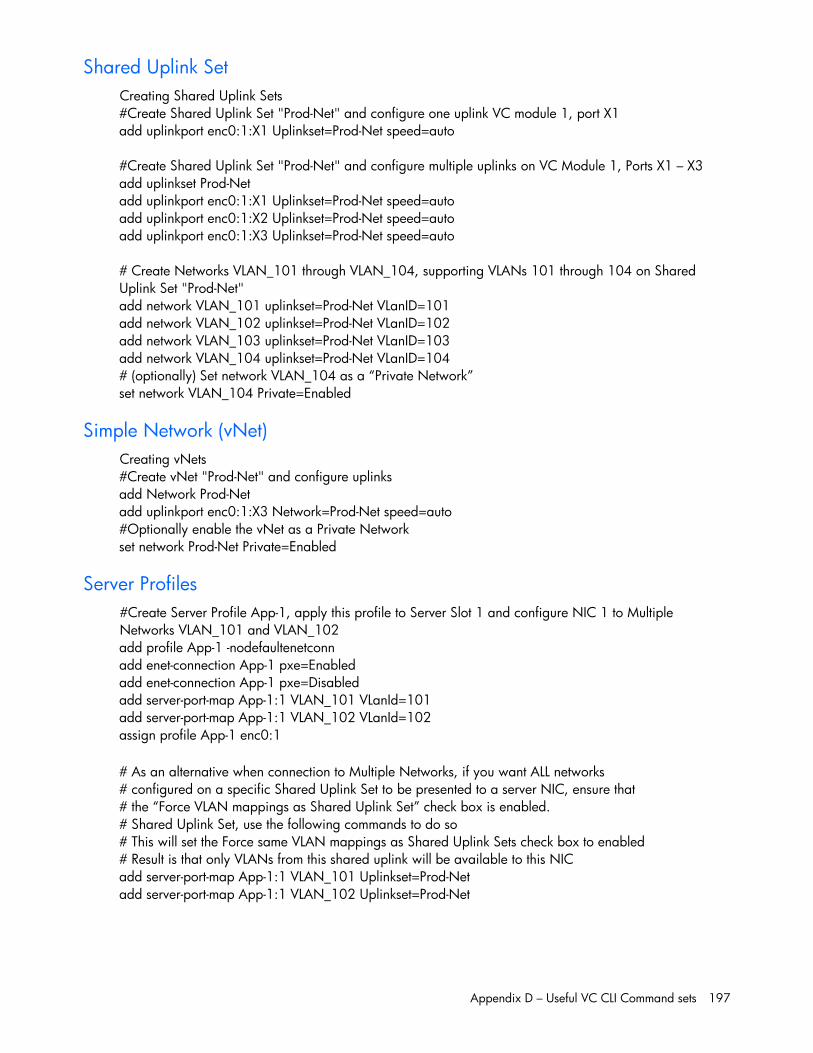
Appendix D – Useful VC CLI Command sets 197
Shared Uplink Set Creating Shared Uplink Sets #Create Shared Uplink Set "Prod-Net" and configure one uplink VC module 1, port X1 add uplinkport enc0:1:X1 Uplinkset=Prod-Net speed=auto #Create Shared Uplink Set "Prod-Net" and configure multiple uplinks on VC Module 1, Ports X1 – X3 add uplinkset Prod-Net add uplinkport enc0:1:X1 Uplinkset=Prod-Net speed=auto add uplinkport enc0:1:X2 Uplinkset=Prod-Net speed=auto add uplinkport enc0:1:X3 Uplinkset=Prod-Net speed=auto # Create Networks VLAN_101 through VLAN_104, supporting VLANs 101 through 104 on Shared Uplink Set "Prod-Net" add network VLAN_101 uplinkset=Prod-Net VLanID=101 add network VLAN_102 uplinkset=Prod-Net VLanID=102 add network VLAN_103 uplinkset=Prod-Net VLanID=103 add network VLAN_104 uplinkset=Prod-Net VLanID=104 # (optionally) Set network VLAN_104 as a “Private Network” set network VLAN_104 Private=Enabled
Simple Network (vNet) Creating vNets #Create vNet "Prod-Net" and configure uplinks add Network Prod-Net add uplinkport enc0:1:X3 Network=Prod-Net speed=auto #Optionally enable the vNet as a Private Network set network Prod-Net Private=Enabled
Server Profiles #Create Server Profile App-1, apply this profile to Server Slot 1 and configure NIC 1 to Multiple Networks VLAN_101 and VLAN_102 add profile App-1 -nodefaultenetconn add enet-connection App-1 pxe=Enabled add enet-connection App-1 pxe=Disabled add server-port-map App-1:1 VLAN_101 VLanId=101 add server-port-map App-1:1 VLAN_102 VLanId=102 assign profile App-1 enc0:1 # As an alternative when connection to Multiple Networks, if you want ALL networks # configured on a specific Shared Uplink Set to be presented to a server NIC, ensure that # the “Force VLAN mappings as Shared Uplink Set” check box is enabled. # Shared Uplink Set, use the following commands to do so # This will set the Force same VLAN mappings as Shared Uplink Sets check box to enabled # Result is that only VLANs from this shared uplink will be available to this NIC add server-port-map App-1:1 VLAN_101 Uplinkset=Prod-Net add server-port-map App-1:1 VLAN_102 Uplinkset=Prod-Net
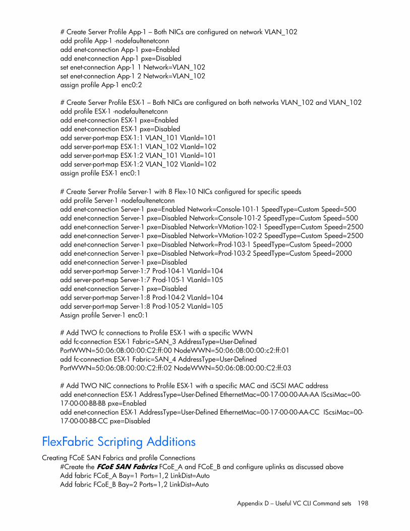
Appendix D – Useful VC CLI Command sets 198
# Create Server Profile App-1 – Both NICs are configured on network VLAN_102 add profile App-1 -nodefaultenetconn add enet-connection App-1 pxe=Enabled add enet-connection App-1 pxe=Disabled set enet-connection App-1 1 Network=VLAN_102 set enet-connection App-1 2 Network=VLAN_102 assign profile App-1 enc0:2 # Create Server Profile ESX-1 – Both NICs are configured on both networks VLAN_102 and VLAN_102 add profile ESX-1 -nodefaultenetconn add enet-connection ESX-1 pxe=Enabled add enet-connection ESX-1 pxe=Disabled add server-port-map ESX-1:1 VLAN_101 VLanId=101 add server-port-map ESX-1:1 VLAN_102 VLanId=102 add server-port-map ESX-1:2 VLAN_101 VLanId=101 add server-port-map ESX-1:2 VLAN_102 VLanId=102 assign profile ESX-1 enc0:1 # Create Server Profile Server-1 with 8 Flex-10 NICs configured for specific speeds add profile Server-1 -nodefaultenetconn add enet-connection Server-1 pxe=Enabled Network=Console-101-1 SpeedType=Custom Speed=500 add enet-connection Server-1 pxe=Disabled Network=Console-101-2 SpeedType=Custom Speed=500 add enet-connection Server-1 pxe=Disabled Network=VMotion-102-1 SpeedType=Custom Speed=2500 add enet-connection Server-1 pxe=Disabled Network=VMotion-102-2 SpeedType=Custom Speed=2500 add enet-connection Server-1 pxe=Disabled Network=Prod-103-1 SpeedType=Custom Speed=2000 add enet-connection Server-1 pxe=Disabled Network=Prod-103-2 SpeedType=Custom Speed=2000 add enet-connection Server-1 pxe=Disabled add server-port-map Server-1:7 Prod-104-1 VLanId=104 add server-port-map Server-1:7 Prod-105-1 VLanId=105 add enet-connection Server-1 pxe=Disabled add server-port-map Server-1:8 Prod-104-2 VLanId=104 add server-port-map Server-1:8 Prod-105-2 VLanId=105 Assign profile Server-1 enc0:1 # Add TWO fc connections to Profile ESX-1 with a specific WWN add fc-connection ESX-1 Fabric=SAN_3 AddressType=User-Defined PortWWN=50:06:0B:00:00:C2:ff:00 NodeWWN=50:06:0B:00:00:c2:ff:01 add fc-connection ESX-1 Fabric=SAN_4 AddressType=User-Defined PortWWN=50:06:0B:00:00:C2:ff:02 NodeWWN=50:06:0B:00:00:C2:ff:03 # Add TWO NIC connections to Profile ESX-1 with a specific MAC and iSCSI MAC address add enet-connection ESX-1 AddressType=User-Defined EthernetMac=00-17-00-00-AA-AA IScsiMac=00-17-00-00-BB-BB pxe=Enabled add enet-connection ESX-1 AddressType=User-Defined EthernetMac=00-17-00-00-AA-CC IScsiMac=00-17-00-00-BB-CC pxe=Disabled
FlexFabric Scripting Additions Creating FCoE SAN Fabrics and profile Connections
#Create the FCoE SAN Fabrics FCoE_A and FCoE_B and configure uplinks as discussed above Add fabric FCoE_A Bay=1 Ports=1,2 LinkDist=Auto Add fabric FCoE_B Bay=2 Ports=1,2 LinkDist=Auto
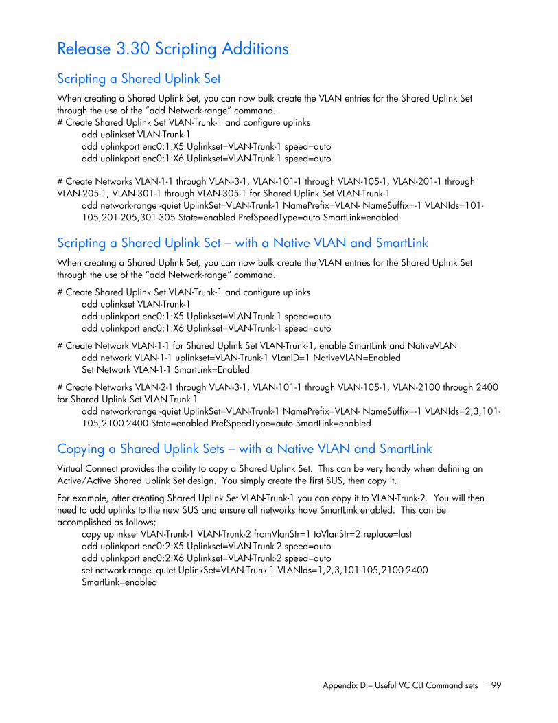
Appendix D – Useful VC CLI Command sets 199
Release 3.30 Scripting Additions
Scripting a Shared Uplink Set When creating a Shared Uplink Set, you can now bulk create the VLAN entries for the Shared Uplink Set through the use of the “add Network-range” command. # Create Shared Uplink Set VLAN-Trunk-1 and configure uplinks
add uplinkset VLAN-Trunk-1 add uplinkport enc0:1:X5 Uplinkset=VLAN-Trunk-1 speed=auto add uplinkport enc0:1:X6 Uplinkset=VLAN-Trunk-1 speed=auto
# Create Networks VLAN-1-1 through VLAN-3-1, VLAN-101-1 through VLAN-105-1, VLAN-201-1 through VLAN-205-1, VLAN-301-1 through VLAN-305-1 for Shared Uplink Set VLAN-Trunk-1
add network-range -quiet UplinkSet=VLAN-Trunk-1 NamePrefix=VLAN- NameSuffix=-1 VLANIds=101-105,201-205,301-305 State=enabled PrefSpeedType=auto SmartLink=enabled
Scripting a Shared Uplink Set – with a Native VLAN and SmartLink When creating a Shared Uplink Set, you can now bulk create the VLAN entries for the Shared Uplink Set through the use of the “add Network-range” command.
# Create Shared Uplink Set VLAN-Trunk-1 and configure uplinks add uplinkset VLAN-Trunk-1 add uplinkport enc0:1:X5 Uplinkset=VLAN-Trunk-1 speed=auto add uplinkport enc0:1:X6 Uplinkset=VLAN-Trunk-1 speed=auto
# Create Network VLAN-1-1 for Shared Uplink Set VLAN-Trunk-1, enable SmartLink and NativeVLAN add network VLAN-1-1 uplinkset=VLAN-Trunk-1 VLanID=1 NativeVLAN=Enabled Set Network VLAN-1-1 SmartLink=Enabled
# Create Networks VLAN-2-1 through VLAN-3-1, VLAN-101-1 through VLAN-105-1, VLAN-2100 through 2400 for Shared Uplink Set VLAN-Trunk-1
add network-range -quiet UplinkSet=VLAN-Trunk-1 NamePrefix=VLAN- NameSuffix=-1 VLANIds=2,3,101-105,2100-2400 State=enabled PrefSpeedType=auto SmartLink=enabled
Copying a Shared Uplink Sets – with a Native VLAN and SmartLink Virtual Connect provides the ability to copy a Shared Uplink Set. This can be very handy when defining an Active/Active Shared Uplink Set design. You simply create the first SUS, then copy it.
For example, after creating Shared Uplink Set VLAN-Trunk-1 you can copy it to VLAN-Trunk-2. You will then need to add uplinks to the new SUS and ensure all networks have SmartLink enabled. This can be accomplished as follows;
copy uplinkset VLAN-Trunk-1 VLAN-Trunk-2 fromVlanStr=1 toVlanStr=2 replace=last add uplinkport enc0:2:X5 Uplinkset=VLAN-Trunk-2 speed=auto add uplinkport enc0:2:X6 Uplinkset=VLAN-Trunk-2 speed=auto set network-range -quiet UplinkSet=VLAN-Trunk-1 VLANIds=1,2,3,101-105,2100-2400 SmartLink=enabled
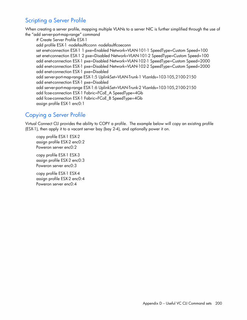
Appendix D – Useful VC CLI Command sets 200
Scripting a Server Profile When creating a server profile, mapping multiple VLANs to a server NIC is further simplified through the use of the “add server-port-map-range” command
# Create Server Profile ESX-1 add profile ESX-1 -nodefaultfcconn -nodefaultfcoeconn set enet-connection ESX-1 1 pxe=Enabled Network=VLAN-101-1 SpeedType=Custom Speed=100 set enet-connection ESX-1 2 pxe=Disabled Network=VLAN-101-2 SpeedType=Custom Speed=100 add enet-connection ESX-1 pxe=Disabled Network=VLAN-102-1 SpeedType=Custom Speed=2000 add enet-connection ESX-1 pxe=Disabled Network=VLAN-102-2 SpeedType=Custom Speed=2000 add enet-connection ESX-1 pxe=Disabled add server-port-map-range ESX-1:5 UplinkSet=VLAN-Trunk-1 VLanIds=103-105,2100-2150 add enet-connection ESX-1 pxe=Disabled add server-port-map-range ESX-1:6 UplinkSet=VLAN-Trunk-2 VLanIds=103-105,2100-2150 add fcoe-connection ESX-1 Fabric=FCoE_A SpeedType=4Gb add fcoe-connection ESX-1 Fabric=FCoE_B SpeedType=4Gb assign profile ESX-1 enc0:1
Copying a Server Profile Virtual Connect CLI provides the ability to COPY a profile. The example below will copy an existing profile (ESX-1), then apply it to a vacant server bay (bay 2-4), and optionally power it on.
copy profile ESX-1 ESX-2 assign profile ESX-2 enc0:2 Poweron server enc0:2
copy profile ESX-1 ESX-3 assign profile ESX-2 enc0:3 Poweron server enc0:3
copy profile ESX-1 ESX-4 assign profile ESX-2 enc0:4 Poweron server enc0:4


![[vc 1037 - listing.archiviolocation.com · [vc 1037] ARCHIVIOLOCATION.COM [vc 1037] ARCHIVIOLOCATION.COM [vc 1037] ARCHIVIOLOCATION.COM [vc 1037] ARCHIVIOLOCATION.COM. archivio location](https://static.fdocuments.net/doc/165x107/5fcd99d1df347e1ae154645c/vc-1037-vc-1037-archiviolocationcom-vc-1037-archiviolocationcom-vc-1037.jpg)

