vav diffusers - Ruskin Titus Gulf LLCdiffusers. RJ-45 cables should be used between diffuser and...
16
Redefine your comfort zone. ™ | www.titus-hvac.com vav diffusers L energy solutions
Transcript of vav diffusers - Ruskin Titus Gulf LLCdiffusers. RJ-45 cables should be used between diffuser and...

Redefine your comfort zone. ™ | www.titus-hvac.com
vav diffusers
L
energy solutions

vav diffusers
L2
L
Rede
fine
your
com
fort
zone
™ |
ww
w.ti
tus-
hvac
.com
VAV
DIF
FUSE
RS
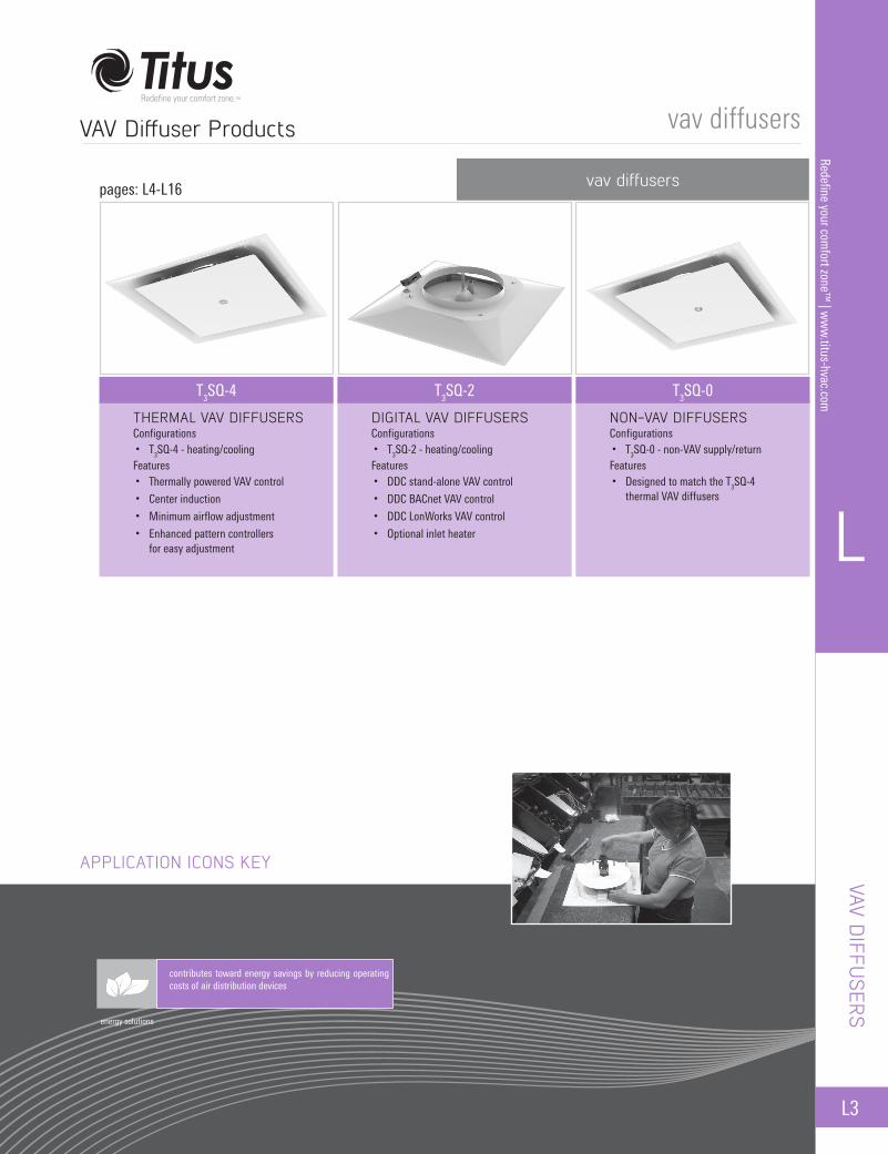
VAV Diffusers Products .........................................................................................................................................................................L3
Table of Contentsvav diffuser products
Application Icons Key ............................................................................................................................................................................L4Design Features .....................................................................................................................................................................................L4
overview
Application Guidelines ..........................................................................................................................................................................L5
Thermal - T3SQ-4 ...................................................................................................................................................................................L7Dimensions ....................................................................................................................................................................................L8
Digital - T3SQ-2 ......................................................................................................................................................................................L9Dimensions ..................................................................................................................................................................................L10Accessories .................................................................................................................................................................................L11
Non-VAV - T3SQ-0 ................................................................................................................................................................................L12Dimensions ..................................................................................................................................................................................L13
Border Types ........................................................................................................................................................................................L14Performance Data ................................................................................................................................................................................L15
application guidelines
vav diffusers
vav diffusers
L
L3
Redefine your comfort zone™
| ww
w.titus-hvac.com
VAV DIFFU
SERS
VAV Diffuser Products
energy solutions
contributes toward energy savings by reducing operating costs of air distribution devices
APPLICATION ICONS KEY
T3SQ-4 T3SQ-2
vav diffusers
T3SQ-0
THERMAL VAV DIFFUSERSConfigurations• T3SQ-4 - heating/coolingFeatures• Thermally powered VAV control
• Center induction
• Minimum airflow adjustment
• Enhanced pattern controllers for easy adjustment
DIGITAL VAV DIFFUSERSConfigurations• T3SQ-2 - heating/coolingFeatures• DDC stand-alone VAV control
• DDC BACnet VAV control
• DDC LonWorks VAV control
• Optional inlet heater
NON-VAV DIFFUSERSConfigurations• T3SQ-0 - non-VAV supply/returnFeatures• Designed to match the T3SQ-4
thermal VAV diffusers
pages: L4-L16
vav diffusers
L4
L
Rede
fine
your
com
fort
zone
™ |
ww
w.ti
tus-
hvac
.com
PERSONALIZED VAV SYSTEMS
Titus brings both accuracy and flexibility to the variable air volume (VAV) market with T3SQ VAV diffusers. The T3SQ combines the functions of a VAV terminal and a high performance diffuser in one. The T3SQ modulates the air volume delivered to a zone to accurately control cooling and heating conditions. The unique variable geometry design results in maximum air distribution effectiveness at any airflow for superior comfort conditions.
T3SQ adds application flexibility by being able to operate stand-alone with thermal or digital controls.
In addition to a superior performance VAV unit, the T3SQ is solidly constructed with 18-gauge steel. Available in many frame styles, the T3SQ can be installed in almost any ceiling as easily as a standard diffuser. The architecturally pleasing design coordinates with any office environment.
For applications that require system simplicity, proven technology and superior comfort, specify the Titus T3SQ series of VAV diffusers.
• Variable geometry diffuser design maintains jet velocity at all flow rates, varying air flow pattern for optimal performance
• Separate cooling and heating setpoints on thermal T3SQ • Supply air temperature provides automatic cooling/heating
changeover on configurations -4 and -2 • T3SQ-2, digital, can control up to 14 drones • Optional electric inlet heater for applications requiring supplemental
heat (T3SQ-2 only) • Provides accurate, personal environmental temperature control to
improve productivity in the office environment
• Superior air distribution performance provides greater entrainment, higher Air Diffusion Performance Index (ADPI) and better ventilation effectiveness for Indoor Air Quality (IAQ)
• Lower cost per zone of control than typical VAV terminal with separate diffusers
• Renovate existing offices or add zones in problem areas to solve individual comfort problems
• Constant volume systems can easily become multi-zoned VAV systems for “big building comfort” on a small building budget
• Easy and inexpensive to relocate zones, ideal for use where office space may be reconfigured periodically
• Easy to install and operate • Unique center induction on thermal T3SQ-4 ensures accurate
readings even at low flows
Overview
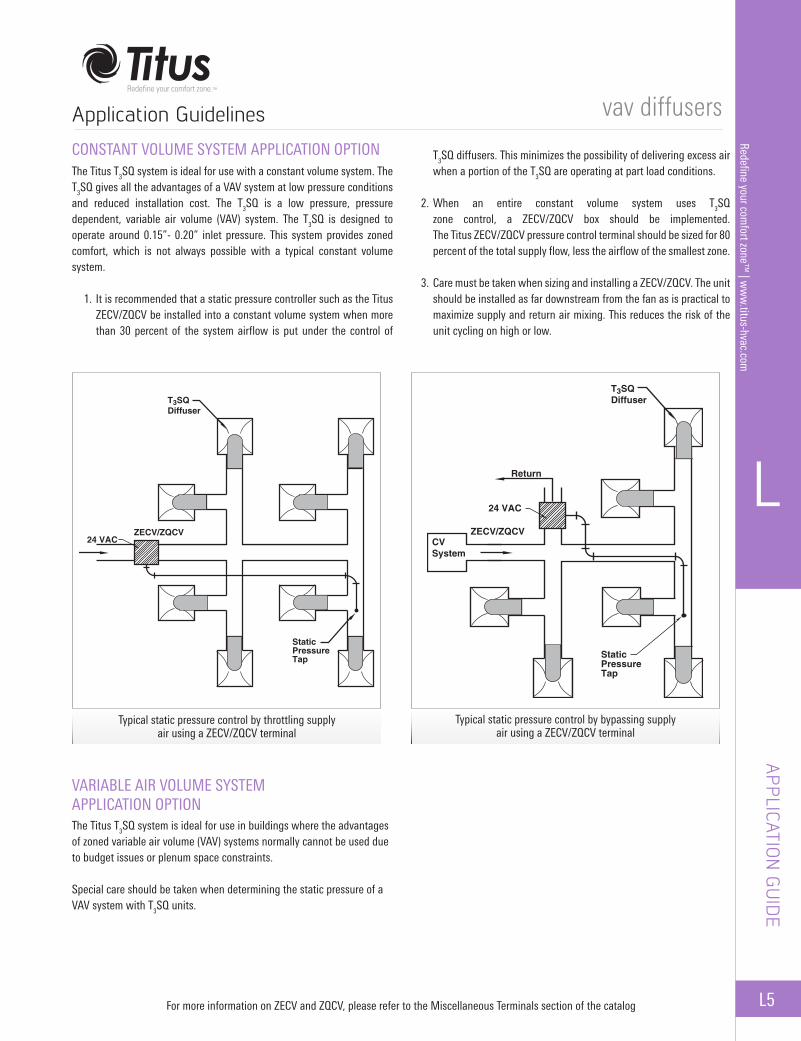
Thermal VAV Diffuser
DESIGN FEATURES
DES
IGN
FEA
TURE
S
Single piece backpan with multiple border types available to complement various ceiling designs.
Easy to turn minimum airflow adjustment ring.
Supply air temperature sensor provides autochangeover from heating to cooling operation. Easy to turn heating and cooling setpoint
adjustment rings (heating setpoint adjusteronly available on heating / cooling units).
Venturi tube and center induction design provide fast and accurate response to changes in zone temperature.
A tight horizontal air pattern is achieved by the intelligent curvature design of the backpan.
Face plaque’s curved edge reduces diffuser sound and creates a smooth appearance.
Thermal actuator assembly lifts and lowers the control disc producing uniform air pattern in all positions.
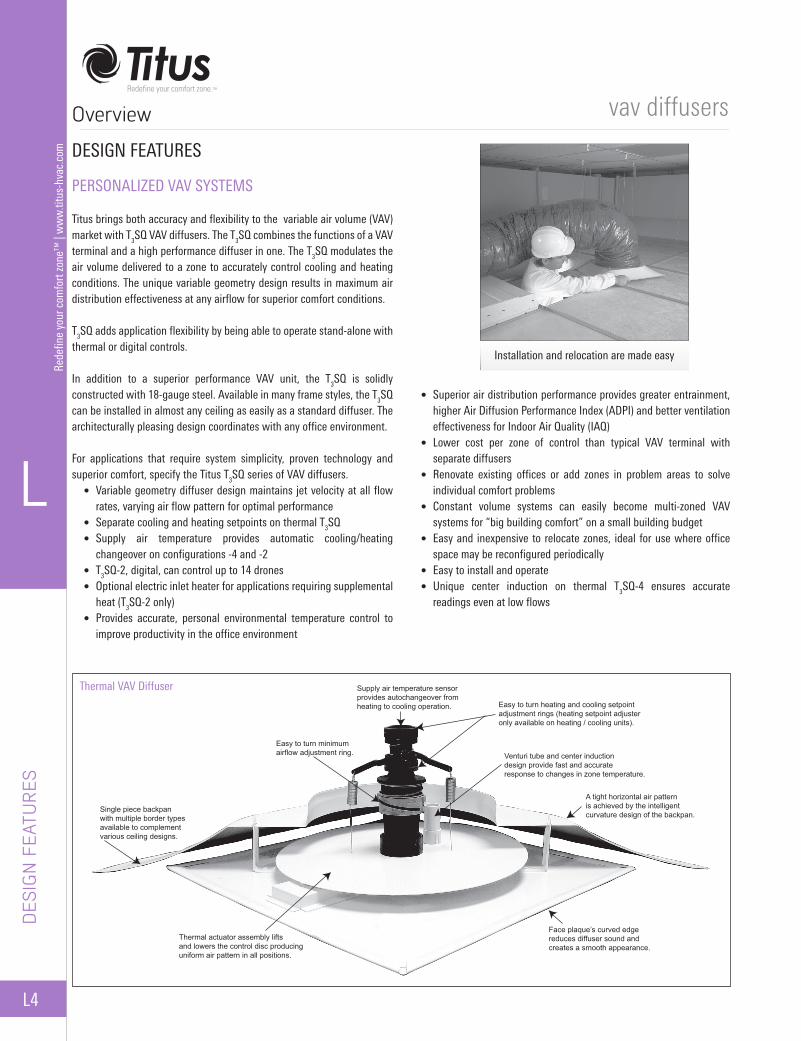
Installation and relocation are made easy
vav diffusers
L
L5
Redefine your comfort zone™
| ww
w.titus-hvac.com
APPLICATION
GU
IDE
CONSTANT VOLUME SYSTEM APPLICATION OPTIONThe Titus T3SQ system is ideal for use with a constant volume system. The T3SQ gives all the advantages of a VAV system at low pressure conditions and reduced installation cost. The T3SQ is a low pressure, pressure dependent, variable air volume (VAV) system. The T3SQ is designed to operate around 0.15”- 0.20” inlet pressure. This system provides zoned comfort, which is not always possible with a typical constant volume system.
1. It is recommended that a static pressure controller such as the Titus ZECV/ZQCV be installed into a constant volume system when more than 30 percent of the system airflow is put under the control of
T3SQ diffusers. This minimizes the possibility of delivering excess air when a portion of the T3SQ are operating at part load conditions.
2. When an entire constant volume system uses T3SQ zone control, a ZECV/ZQCV box should be implemented. The Titus ZECV/ZQCV pressure control terminal should be sized for 80 percent of the total supply flow, less the airflow of the smallest zone.
3. Care must be taken when sizing and installing a ZECV/ZQCV. The unit should be installed as far downstream from the fan as is practical to maximize supply and return air mixing. This reduces the risk of the unit cycling on high or low.
VARIABLE AIR VOLUME SYSTEM APPLICATION OPTIONThe Titus T3SQ system is ideal for use in buildings where the advantages of zoned variable air volume (VAV) systems normally cannot be used due to budget issues or plenum space constraints.
Special care should be taken when determining the static pressure of a VAV system with T3SQ units.
For more information on ZECV and ZQCV, please refer to the Miscellaneous Terminals section of the catalog
Application Guidelines
T3SQDiffuser
24 VAC
ZECV/ZQCVCVSystem
Return
StaticPressureTap
T3SQDiffuser
24 VACZECV/ZQCV
StaticPressureTap
Typical static pressure control by throttling supply air using a ZECV/ZQCV terminal
Typical static pressure control by bypassing supply air using a ZECV/ZQCV terminal
vav diffusers
L6
L
Rede
fine
your
com
fort
zone
™ |
ww
w.ti
tus-
hvac
.com
APPL
ICAT
ION
GU
IDE
T3SQ-2 diffusers are all shipped as drone units. Determination of master units is made through plug and play cable connections to the thermostat. The units connected to the thermostat are the master units. All units daisy chained from the master are drones. Drone diffusers must be connected to a master diffuser in order to operate. One power module is required for every 15 diffusers with or without optional electric reheat. Power module requires 120, 208, 240, 277 VAC line voltage input.
The 4-pin mini-fit cables provide 24VAC power and communication between diffusers. This cable should be used between the power module and the first diffuser and also to connect a master unit to a drone unit.
Blue RJ-45 8-pin cables provide 24VAC power and control signal between diffusers. RJ-45 cables should be used between diffuser and master controller/thermostat and between master and drone units.
The Master Communications Module is a central data collection and distribution point for up to 60 VAV field diffusers. The device features four diffuser channel inputs, which can accommodate up to 15 diffusers each. This allows the users to interface with 60 diffusers per communication module through a building management system. The interface software also has a server application which allows all communication modules on site to be accessed through the building management system from the IP address of each module. Master communication modules are available in the following communication protocols:
• Standard Master Communication module (Stand-Alone)• Master Communications module with Lonworks gateway• Master Communications module with BACnet gateway
Application Guidelines (continued)
MASTER / DRONE
Master/Drone Wiring
One master unit can control up to 14 drone units.
P.S. = Power SupplyT = Room Sensor
Digital VAV Diffuser
Master/Drone Wiring With MCM (Master Communication Module)
P.S. = Power SupplyT = Room SensorMCM = Master Communication Module
RJ124-pin mini fit cable drone unitRJ-9 cable
RJ124-pin mini fit cable drone unit
P.S.
MCM
T
T
P.S.
Master Unit
Master Unit
Drone Unit
Drone Unit
Drone Unit
Drone Unit
Drone Unit
Drone Unit
vav diffusers
L
L7
Redefine your comfort zone™
| ww
w.titus-hvac.com
VAV Diffusers
T3 SQ
-4
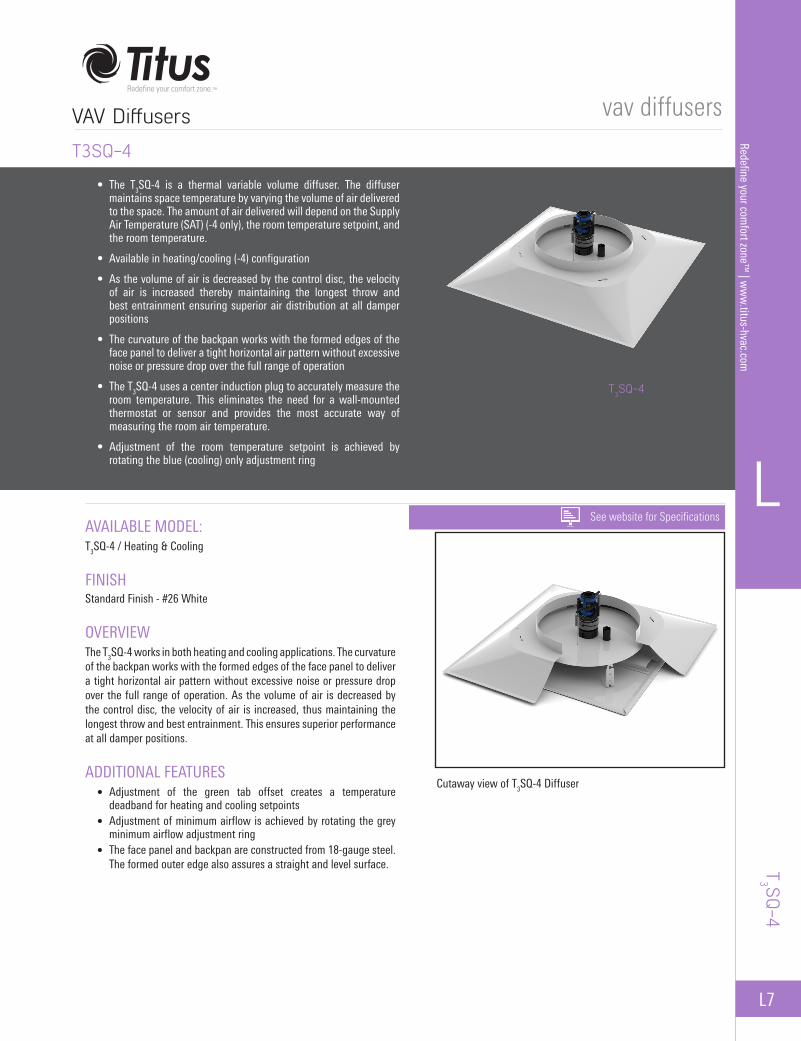
T3SQ-4
AVAILABLE MODEL:T3SQ-4 / Heating & Cooling
FINISHStandard Finish - #26 White
OVERVIEWThe T3SQ-4 works in both heating and cooling applications. The curvature of the backpan works with the formed edges of the face panel to deliver a tight horizontal air pattern without excessive noise or pressure drop over the full range of operation. As the volume of air is decreased by the control disc, the velocity of air is increased, thus maintaining the longest throw and best entrainment. This ensures superior performance at all damper positions.
ADDITIONAL FEATURES • Adjustment of the green tab offset creates a temperature
deadband for heating and cooling setpoints • Adjustment of minimum airflow is achieved by rotating the grey
minimum airflow adjustment ring • The face panel and backpan are constructed from 18-gauge steel.
The formed outer edge also assures a straight and level surface.
• The T3SQ-4 is a thermal variable volume diffuser. The diffuser maintains space temperature by varying the volume of air delivered to the space. The amount of air delivered will depend on the Supply Air Temperature (SAT) (-4 only), the room temperature setpoint, and the room temperature.
• Available in heating/cooling (-4) configuration
• As the volume of air is decreased by the control disc, the velocity of air is increased thereby maintaining the longest throw and best entrainment ensuring superior air distribution at all damper positions
• The curvature of the backpan works with the formed edges of the face panel to deliver a tight horizontal air pattern without excessive noise or pressure drop over the full range of operation
• The T3SQ-4 uses a center induction plug to accurately measure the room temperature. This eliminates the need for a wall-mounted thermostat or sensor and provides the most accurate way of measuring the room air temperature.
• Adjustment of the room temperature setpoint is achieved by rotating the blue (cooling) only adjustment ring
Cutaway view of T3SQ-4 Diffuser
T3SQ-4
See website for Specifications
vav diffusers
L8
L
Rede
fine
your
com
fort
zone
™ |
ww
w.ti
tus-
hvac
.com
DIM
ENSI
ON
S
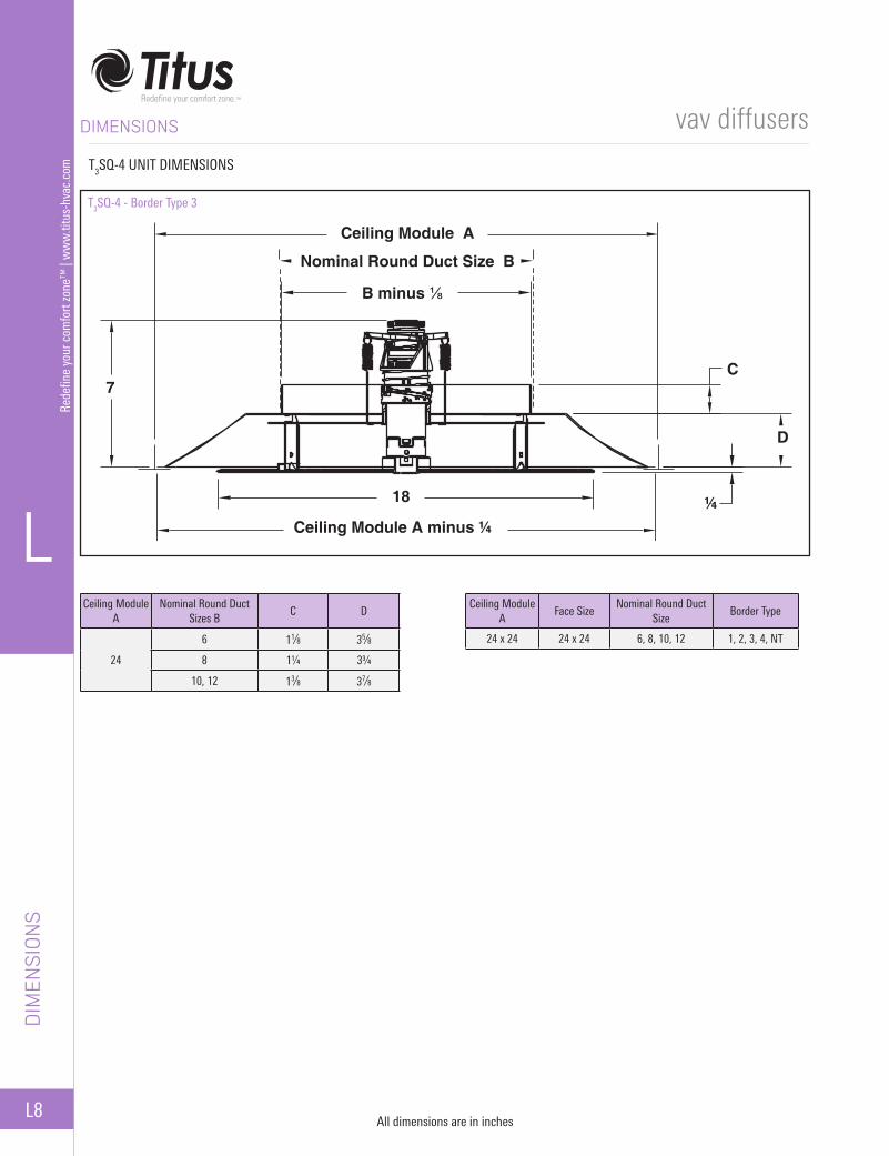
DIMENSIONS
Ceiling Module A
Face SizeNominal Round Duct
SizeBorder Type
24 x 24 24 x 24 6, 8, 10, 12 1, 2, 3, 4, NT
Ceiling Module A
Nominal Round Duct Sizes B
C D
24
6 11⁄8 35⁄8
8 1¼ 3¾
10, 12 13⁄8 37⁄8
T3SQ-4 - Border Type 3
Ceiling Module A
Nominal Round Duct Size B
B minus ⅛
C
D
¼Ceiling Module A minus ¼
18
7
T3SQ-4 UNIT DIMENSIONS
All dimensions are in inches

vav diffusers
L
L9
Redefine your comfort zone™
| ww
w.titus-hvac.com
VAV Diffusers (continued)
T3 SQ
-2
T3SQ-2
AVAILABLE MODEL:T3SQ-2 / Heating & Cooling
FINISHStandard Finish - #26 White
OVERVIEWThe Digital T3SQ-2 is the most energy efficient VAV diffuser on the market. It requires 10 times less power than the competitor’s model. The communication modules allow for interfacing with building management systems for all major communication protocols. With user friendly software to control and commission diffusers, the Digital T3SQ -2 is the next level of VAV diffusers on the market.
ADDITIONAL FEATURES • The position of the control disc is varied by a linear drive actuator
mounted on the control disc • The face panel and backpan are constructed from 18-gauge steel.
The formed outer edge also assures a straight and level surface.
• The T3SQ-2 is an electronic variable volume diffuser. The diffuser maintains space temperature by varying the volume of air delivered to the space. The amount of air delivered will depend on the Supply Air Temperature (SAT) (-4 only), the room temperature setpoint, and the room temperature.
• As the volume of air is decreased by the control disc, the velocity of air is increased thereby maintaining the longest throw and best entrainment. This ensures superior air distribution at all damper positions.
• The curvature of the backpan works with the formed edges of the face panel to deliver a tight horizontal air pattern without excessive noise or pressure drop over the full range of operation
• T3SQ-2 master diffusers are created by connecting the diffuser to a wall mounted controller/thermostat using the RJ-12 control cable
• T3SQ-2 drone diffusers are created by connecting the diffuser to a master unit using the 4-pin mini-fit control cable
• Up to fifteen T3SQ-2 diffusers can be powered by a single power module using the 4-pin mini-fit power cable
Exploded view of T3SQ-2 diffuser
T3SQ-2
energy solutions
See website for Specifications

vav diffusers
L10
L
Rede
fine
your
com
fort
zone
™ |
ww
w.ti
tus-
hvac
.com
DIM
ENSI
ON
S
DIMENSIONS
T3SQ-2 / Border Type 3
All dimensions are in inches
T3SQ-2 UNIT DIMENSIONS
Ceiling Module A
Face SizeNominal Round Duct
SizeBorder Type
24 x 24 24 x 24 6, 8, 10, 12 1, 2, 3, 4, NT
Ceiling Module A
Nominal Round Duct Sizes B
C D
24
6 11⁄8 35⁄8
8 1¼ 3¾
10, 12 13⁄8 37⁄8

vav diffusers
L
L11
Redefine your comfort zone™
| ww
w.titus-hvac.com
OPTIONAL INLET ELECTRIC HEATER • Installs into neck of diffuser • 120V, 208V or 277V single phase
input power (field connect) • Black heat element • SCR modulating heater control • Ships loose for field installation • Integrated wiring interface box • Automatic reset thermal cutout • Manual reset secondary protection
CABLES (HEATER CONNECTION) • Blue RJ-45 (8-pin straight through
pinout) for control and power • Modular connector that attaches the
ribbon cable and RJ45 to heater
ACCESSORIES
ACCESSORIES
RELIEF RINGS • Used to bypass supply air into the ceiling
plenum as the diffuser turns down • Available for both digital and
thermal configurations • Effectively reduces inlet size by 2 inches
MASTER COMMUNICATION MODULE • Available with Standard (Titus)
communication module, BACnet, or Lonworks gateway
• MCM is the central data collection and distribution point for up to 60 VAV field diffusers per module
• Features four diffuser channel inputs which can accommodate up to 15 diffusers per channel, per communication module (MCM)
• Interface software is designed as a commissioning tool as well as for data monitoring, logging, and fault finding
• Software is supplied with each shipment
CONTROLLER/THERMOSTAT • Each master T3SQ-2 diffuser requires a
controller / thermostat • 24VAC RJ-12 control cable connection • Room sensor with LCD display real time
clock for night set-back & control disc position display
• Provides Setpoint Temperature adjustment & room temp display
• Interfaces with a USB module in order to interface with software for further functionality
• Dimensions are 3” x 3 ¼”
24V output
Field connect line voltage
3⅝
4⅝
2⅞
Nominal Duct Size B minus ⅛
4½
Available kW:Inlet Size
Voltage FLA
120V 208V 277V 120V 208V 277V
6 0.75 0.75 0.75 6.3 3.6 2.7
8 1.00 1.00 1.00 8.3 4.8 3.6
10 1.25 1.50 1.50 10.4 7.2 5.4
12 1.25 2.00 2.00 10.4 9.6 7.2
LCD SCREEN
UP
DOWN
FUNCTION
ENTER / ACCEPT

vav diffusers
L12
L
Rede
fine
your
com
fort
zone
™ |
ww
w.ti
tus-
hvac
.com
T 3SQ
-0
VAV Diffusers (continued)
AVAILABLE MODEL:T3SQ-0 / Heating & Cooling
FINISHStandard Finish - #26 White
OVERVIEWThe T3SQ-0 is a non-VAV supply or return diffuser with a center induction cap designed to match the T3SQ-4 thermal VAV diffusers.
T3SQ-0
• The T3SQ-0 is a non-VAV supply or return diffuser with a center induction cap designed to match the T3SQ-4 thermal VAV diffusers
• The curvature of the backpan works with the formed edges of the face panel to deliver a tight horizontal air pattern, without excessive noise or pressure drop over the full range of operation
• The T3SQ diffuser is designed to satisfy architectural, as well as engineering criteria. The strong, clean, unobtrusive lines harmonize with the ceiling, without sacrificing performance.
• The face panel and backpan are constructed from 18-gauge steel. The formed outer edge also assures a straight and level surface.
T3SQ-0
See website for Specifications
vav diffusers
L
L13
Redefine your comfort zone™
| ww
w.titus-hvac.com
DIM
ENSIO
NS
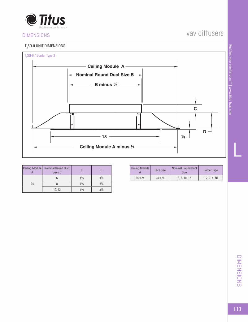
DIMENSIONS
T3SQ-0 UNIT DIMENSIONS
Ceiling Module A
Face SizeNominal Round Duct
SizeBorder Type
24 x 24 24 x 24 6, 8, 10, 12 1, 2, 3, 4, NT
Ceiling Module A
Nominal Round Duct Sizes B
C D
24
6 11⁄8 35⁄8
8 1¼ 3¾
10, 12 13⁄8 37⁄8
T3SQ-0 / Border Type 3
Ceiling Module A minus ¼
18
B minus ⅛
Nominal Round Duct Size B
Ceiling Module A
D
C
¼
vav diffusers
L14
L
Rede
fine
your
com
fort
zone
™ |
ww
w.ti
tus-
hvac
.com BORDER TYPES
All dimensions are in inches
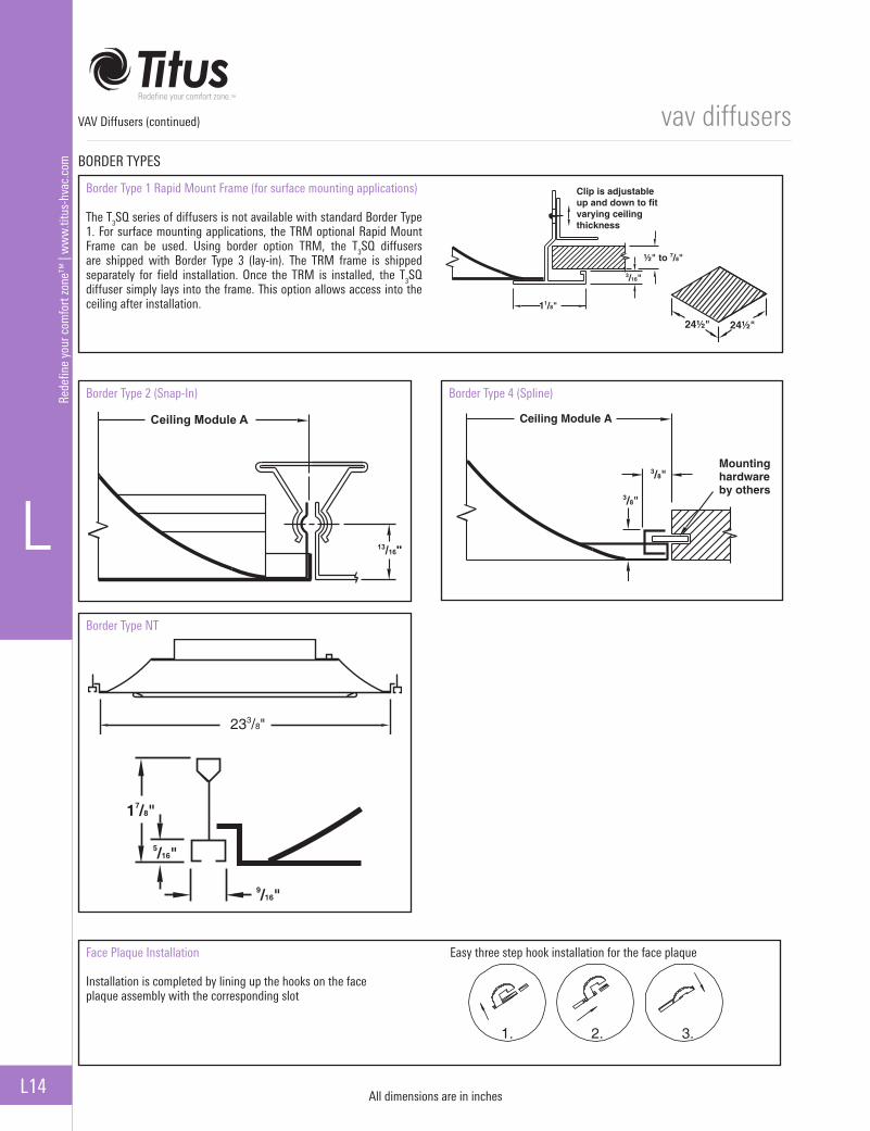
Border Type 1 Rapid Mount Frame (for surface mounting applications)
The T3SQ series of diffusers is not available with standard Border Type 1. For surface mounting applications, the TRM optional Rapid Mount Frame can be used. Using border option TRM, the T3SQ diffusers are shipped with Border Type 3 (lay-in). The TRM frame is shipped separately for field installation. Once the TRM is installed, the T3SQ diffuser simply lays into the frame. This option allows access into the ceiling after installation.
Clip is adjustableup and down to fitvarying ceilingthickness
½" to 7/8"
3/16"
11/8"
24½" 24½"
Border Type 2 (Snap-In) Border Type 4 (Spline)
13/16"
Ceiling Module A Ceiling Module A
3/8"
3/8"
Mountinghardwareby others
Border Type NT
233/8"
17/8"
9/16"
5/16"
Face Plaque Installation Easy three step hook installation for the face plaque
Installation is completed by lining up the hooks on the face plaque assembly with the corresponding slot
1. 2. 3.
VAV Diffusers (continued)

vav diffusers
L
L15
Redefine your comfort zone™
| ww
w.titus-hvac.com
PERFORM
ANCE D
ATA
PERFORMANCE DATA
T3SQ MAXIMUM FLOW SELECTION
Inlet SizeNeck Velocity 400 500 600 700 800 900 1000
Velocity Pressure 0.010 0.016 0.022 0.031 0.040 0.050 0.062
6”
Static pressure 0.016 0.024 0.037 0.048 0.064 0.082 0.100Total Pressure 0.026 0.040 0.059 0.079 0.104 0.132 0.162
cfm 79 98 118 137 157 177 196NC 5 10 14 17 20 23 25
Throw, ft 1-2-3 1-2-4 2-3-5 2-3-6 2-3-7 3-4-7 3-4-8
8”
Static pressure 0.021 0.032 0.047 0.063 0.083 0.106 0.130Total Pressure 0.031 0.048 0.069 0.094 0.123 0.156 0.192
cfm 140 175 209 244 279 314 349NC 8 13 17 20 23 25 28
Throw, ft 2-3-5 2-3-7 2-4-8 3-5-9 3-5-10 4-6-10 4-7-11
10”
Static pressure 0.030 0.047 0.069 0.093 0.122 0.155 0.190Total Pressure 0.040 0.063 0.091 0.124 0.162 0.205 0.252
cfm 218 273 327 382 436 491 545NC 14 19 23 26 29 31 34
Throw, ft 3-4-8 4-5-10 4-6-11 5-8-12 6-9-13 6-10-14 7-10-14
12”
Static pressure 0.048 0.075 0.109 0.147 0.192 0.244 0.301Total Pressure 0.058 0.091 0.131 0.178 0.232 0.294 0.363
cfm 314 393 471 550 628 707 785NC 24 29 33 36 39 41 44
Throw, ft 4-6-11 5-8-12 6-9-13 7-10-14 8-11-15 9-11-16 10-12-17
T3SQ AHRI RATING
AHRI Rating Data Inlet Size 6” Inlet 8” Inlet 10” Inlet 12” Inlet
Stan
dard
Rat
ings
Sou
nd P
ower
Lev
el, d
B
3. Airflow, cfm 147 262 409 5894. Min. Operating Pressure, in H20 0.091 0.108 0.142 0.2045. Max. Inlet Static Pressure @ 400 fpm Neck Velocity, in H20
0.116 0.196 0.392 0.565
6. Rated with Pressure Relief, yes/no n n n n
Disc
harg
e
Stan
dard
Airf
low
Fu
lly o
pen
dam
per
750
fpm
Nec
k Ve
loci
ty
Min
imum
Diff
eren
tial
Stat
ic P
ress
ure,
in
H20
Hz O
ctav
e Ba
nd C
ente
r Fre
quen
cy
125 36 38 46 53
250 37 40 48 56
500 34 36 42 50
1000 30 34 39 44
2000 21 29 32 364000 + 19 23 28
Disc
harg
e
Stan
dard
Airf
low
Th
rottl
ed D
ampe
r 40
0 fp
m N
eck
Velo
city
Max
. Inl
et S
tatic
Pr
essu
re,
in H
2O
125 + 44 46 50250 36 52 54 55
500 40 57 58 60
1000 34 51 55 58
2000 23 44 48 52
4000 + 37 42 47
Note: Sound Power levels below values shown in this table shall be listed as below significance. Use a plus sign (+) to indicate below significance.
Hz Octave Band 125 250 500 1000 2000 4000Sound Power Level, dB 36 29 26 22 19 17
Performance data is presented for the T3SQ diffuser with the internal VAV damper in full open position
vav diffusers
L16
L
Rede
fine
your
com
fort
zone
™ |
ww
w.ti
tus-
hvac
.com
PERF
ORM
ANCE
DAT
A
PERFORMANCE DATA
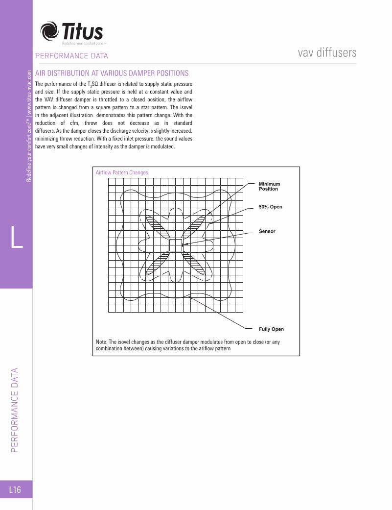
AIR DISTRIBUTION AT VARIOUS DAMPER POSITIONSThe performance of the T3SQ diffuser is related to supply static pressure and size. If the supply static pressure is held at a constant value and the VAV diffuser damper is throttled to a closed position, the airflow pattern is changed from a square pattern to a star pattern. The isovel in the adjacent illustration demonstrates this pattern change. With the reduction of cfm, throw does not decrease as in standard diffusers. As the damper closes the discharge velocity is slightly increased, minimizing throw reduction. With a fixed inlet pressure, the sound values have very small changes of intensity as the damper is modulated.
Airflow Pattern Changes
Note: The isovel changes as the diffuser damper modulates from open to close (or any combination between) causing variations to the ariflow pattern
MinimumPosition
50% Open
Sensor
Fully Open