Vauxhall Corsa Owner's Manual · Vauxhall Corsa Owner's Manual. ... Press c to unlock the doors and...
265
Vauxhall Corsa Owner's Manual
Transcript of Vauxhall Corsa Owner's Manual · Vauxhall Corsa Owner's Manual. ... Press c to unlock the doors and...

Vauxhall CorsaOwner's Manual


Introduction .................................... 2In brief ............................................ 6Keys, doors and windows ............ 20Seats, restraints ........................... 35Storage ........................................ 57Instruments and controls ............. 75Lighting ...................................... 112Climate control ........................... 122Driving and operating ................. 132Vehicle care ............................... 187Service and maintenance .......... 234Technical data ........................... 237Customer information ................ 252Index .......................................... 258
Contents

2 Introduction
Introduction

Introduction 3
Vehicle specific dataPlease enter your vehicle's data onthe previous page to keep it easilyaccessible. This information isavailable in the sections "Service andmaintenance" and "Technical data"as well as on the identification plate.
IntroductionYour vehicle is a designedcombination of advanced technology,safety, environmental friendlinessand economy.This Owner's Manual provides youwith all the necessary information toenable you to drive your vehiclesafely and efficiently.Make sure your passengers areaware of the possible risk of accidentand injury which may result fromimproper use of the vehicle.You must always comply with thespecific laws and regulations of thecountry that you are in. These lawsmay differ from the information in thisOwner's Manual.Disregarding the description given inthis manual may affect your warranty.
When this Owner's Manual refers to aworkshop visit, we recommend yourVauxhall Authorised Repairer.For gas vehicles, we recommend aVauxhall Authorised Repairerlicensed to service gas vehicles.All Vauxhall Authorised Repairersprovide first-class service atreasonable prices. Experiencedmechanics trained by Vauxhall workaccording to specific Vauxhallinstructions.The customer literature pack shouldalways be kept ready to hand in thevehicle.
Using this manual● This manual describes all options
and features available for thismodel. Certain descriptions,including those for display andmenu functions, may not apply toyour vehicle due to modelvariant, country specifications,special equipment oraccessories.
● The "In brief" section will give youan initial overview.
● The table of contents at thebeginning of this manual andwithin each section shows wherethe information is located.
● The index will enable you tosearch for specific information.
● This Owner's Manual depicts left-hand drive vehicles. Operation issimilar for right-hand drivevehicles.
● The Owner's Manual uses theengine identifier code. Thecorresponding sales designationand engineering code can befound in the section "Technicaldata".
● Directional data, e.g. left or right,or front or back, always relate tothe direction of travel.
● Displays may not support yourspecific language.
● Display messages and interiorlabelling are written in boldletters.

4 Introduction
Danger, Warnings andCautions
9 Danger
Text marked 9 Danger providesinformation on risk of fatal injury.Disregarding this information mayendanger life.
9 Warning
Text marked 9 Warning providesinformation on risk of accident orinjury. Disregarding thisinformation may lead to injury.
Caution
Text marked Caution providesinformation on possible damage tothe vehicle. Disregarding thisinformation may lead to vehicledamage.
SymbolsPage references are indicated with 3.3 means "see page".Page references and index entriesrefer to the indented headings givenin the section table of content.Thank you for choosing a Vauxhall.We wish you many hours ofpleasurable driving.Your Vauxhall Team

Introduction 5

6 In brief
In brief
Initial drive information
Vehicle unlocking
Press c to unlock the doors and loadcompartment. Open the doors bypulling the handles.
To open the tailgate, push thetouchpad switch below the brandemblem.Radio remote control 3 21, Centrallocking system 3 22, Loadcompartment 3 25.

In brief 7
Seat adjustmentLongitudinal adjustment
Pull handle, slide seat, releasehandle. Try to move the seat back andforth to ensure that the seat is lockedin place.Seat position 3 36, Seat adjustment3 37.
Backrest inclination
Turn handwheel. Do not lean onbackrest while adjusting.Seat position 3 36, Seat adjustment3 37, Seat folding 3 38, Sport seat3 38.
Seat height
Lever pumping motionup : seat higherdown : seat lower
Seat position 3 36, Seat adjustment3 37.

8 In brief
Head restraint adjustment
Press release button, adjust height,engage.Head restraints 3 35.
Seat belt
Pull out the seat belt and engage inbelt buckle. The seat belt must not betwisted and must fit close against thebody. The backrest must not be tiltedback too far (maximum approx. 25 °).To release belt, press red button onbelt buckle.Seat position 3 36, Seat belts3 40, Airbag system 3 43.
Mirror adjustmentInterior mirror
To adjust the mirror, move the mirrorhousing in the desired direction.Manual anti-dazzle interior mirror3 29.Automatic anti-dazzle interior mirror3 30.

In brief 9
Exterior mirrors
Select the relevant exterior mirror withthe rocker switch and adjust themirror with the control :.Convex exterior mirrors 3 28,Electric adjustment 3 28, Foldingexterior mirrors 3 29.Heated exterior mirrors 3 29.
Steering wheel adjustment
Unlock the lever, adjust the steeringwheel, then engage the lever andensure it is fully locked.Do not adjust the steering wheelunless the vehicle is stationary andthe steering wheel lock has beenreleased.Airbag system 3 43, Ignitionpositions 3 133.
10 In brief
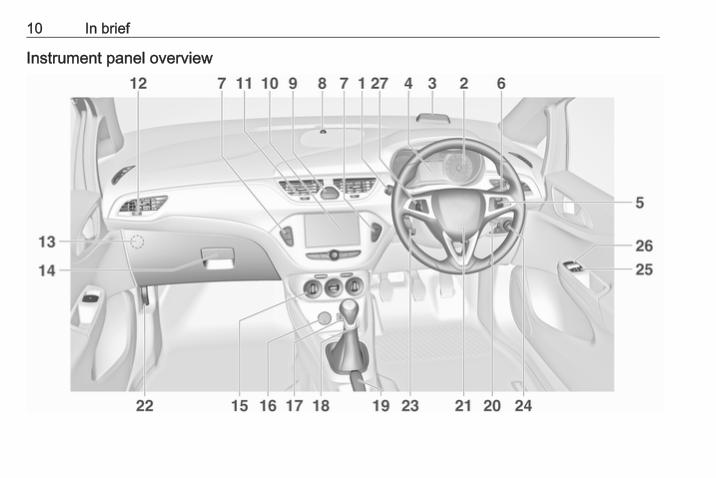
Instrument panel overview
In brief 11
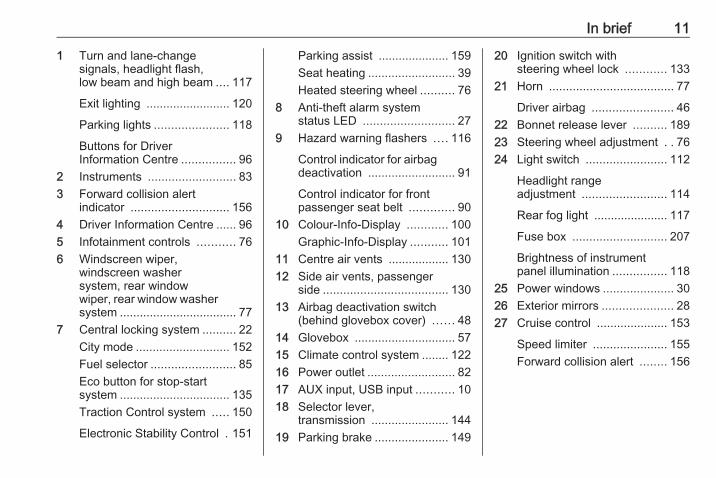
1 Turn and lane-changesignals, headlight flash,low beam and high beam .... 117
Exit lighting ......................... 120
Parking lights ...................... 118
Buttons for DriverInformation Centre ................ 96
2 Instruments .......................... 833 Forward collision alert
indicator ............................. 1564 Driver Information Centre ...... 965 Infotainment controls ........... 766 Windscreen wiper,
windscreen washersystem, rear windowwiper, rear window washersystem ................................... 77
7 Central locking system .......... 22City mode ............................ 152Fuel selector ......................... 85Eco button for stop-startsystem ................................. 135Traction Control system ..... 150
Electronic Stability Control . 151
Parking assist ..................... 159Seat heating .......................... 39Heated steering wheel .......... 76
8 Anti-theft alarm systemstatus LED ........................... 27
9 Hazard warning flashers .... 116
Control indicator for airbagdeactivation .......................... 91
Control indicator for frontpassenger seat belt ............. 90
10 Colour-Info-Display ............ 100Graphic-Info-Display ........... 101
11 Centre air vents .................. 13012 Side air vents, passenger
side ..................................... 13013 Airbag deactivation switch
(behind glovebox cover) ...... 4814 Glovebox .............................. 5715 Climate control system ........ 12216 Power outlet .......................... 8217 AUX input, USB input ........... 1018 Selector lever,
transmission ....................... 14419 Parking brake ...................... 149
20 Ignition switch withsteering wheel lock ............ 133
21 Horn ..................................... 77
Driver airbag ........................ 4622 Bonnet release lever .......... 18923 Steering wheel adjustment . . 7624 Light switch ........................ 112
Headlight rangeadjustment ......................... 114
Rear fog light ...................... 117
Fuse box ............................ 207
Brightness of instrumentpanel illumination ................ 118
25 Power windows ..................... 3026 Exterior mirrors ..................... 2827 Cruise control ..................... 153
Speed limiter ...................... 155Forward collision alert ........ 156

12 In brief
Exterior lightingLight switch
Turn light switch:7 : lights off8 : sidelights9 : headlights
Fog lightsPress buttons in light switch:> : front fog lightsr : rear fog light
Light switch with automatic lightcontrol
AUTO : automatic light control:exterior lighting is switchedon and off automatically
m : activation or deactivation ofthe automatic light control
8 : sidelights9 : headlights
Automatic light control 3 113.
Headlight flash, high beam andlow beam
headlight flash : pull leverhigh beam : push leverlow beam : push or pull lever
High beam 3 114, Headlight flash3 114, High beam assist 3 115.

In brief 13
Turn and lane-change signals
lever up : right turn signallever down : left turn signal
Turn and lane-change signals3 117, Parking lights 3 118.
Hazard warning flashers
Operated by pressing ¨.Hazard warning flashers 3 116.
Horn
Press j.

14 In brief
Washer and wiper systemsWindscreen wiper
HI : fastLO : slowINT : interval wiping
orautomatic wiping with rainsensor
OFF : off
For single wipe when the wiper is off,press lever down to position 1x.Windscreen wiper 3 77.
Windscreen washer
Pull lever.Windscreen washer system 3 77,Washer fluid 3 193, Wiper bladereplacement 3 195.
Rear window wiper
Press the rocker switch to activate therear window wiper:upper switch : continuous
operationlower switch : intermittent
operationmiddle position : off

In brief 15
Rear window washer
Push lever.Washer fluid is sprayed on the rearwindow and the wiper wipes a fewtimes.Rear window wiper/washer 3 79.
Climate controlHeated rear window
The heating is operated by pressingÜ.Heated rear window 3 32.Heated windscreen 3 32.
Heated exterior mirrorsPressing Ü also activates the heatedexterior mirrors.Heated exterior mirrors 3 29.
Demisting and defrosting thewindows
● Set air distribution control to l.● Press V.● Set temperature control to
warmest level.● Set fan speed to highest level.● Switch on heated rear window Ü.● Open side air vents as required
and direct them towards the doorwindows.
Climate control system 3 122.

16 In brief
TransmissionManual transmission
Reverse: with the vehicle stationary,depress clutch pedal and press therelease button on the selector leverand engage the gear.If the gear does not engage, set thelever to neutral, release the clutchpedal and depress again; then repeatgear selection.Manual transmission 3 144.
Automatic transmission
P : parkR : reverseN : neutralD : driveM : manual mode< : press to upshift in manual mode] : press to downshift in manual
mode
The selector lever can only be movedout of P when the ignition is on andthe brake pedal is applied. To engageP or R, press the release button.Automatic transmission 3 140.
Manual transmission automated
R : reverse, engage only whenvehicle is stationary
N : neutralD : automatic modeM : manual mode< : upshift in manual mode] : downshift in manual mode
Manual transmission automated3 144.

In brief 17
Starting offCheck before starting off● Tyre pressure and condition
3 211, 3 250.● Engine oil level and fluid levels
3 190.● All windows, mirrors, exterior
lighting and number plates arefree from dirt, snow and ice andare operational.
● Proper position of mirrors, seats,and seat belts 3 28, 3 36,3 41.
● Brake function at low speed,particularly if the brakes are wet.
Starting the engine
● Turn key to position 1.● Move the steering wheel slightly
to release the steering wheellock.
● Manual transmission: operateclutch and brake pedal.Manual transmission automated:operate brake pedal.Automatic transmission: operatebrake pedal and move selectorlever to P or N.
● Do not operate accelerator pedal.
● Diesel engines: turn the key toposition 2 for preheating and waituntil control indicator !extinguishes.
● Turn the key to position 2 forpreheating and wait until controlindicator ! extinguishes.
● Turn key to position 3 andrelease.
Starting the engine 3 134.

18 In brief
Stop-start system
If the vehicle is at a low speed or at astandstill and certain conditions arefulfilled, activate an Autostop asfollows:
Vehicles with manual transmission:● Depress the clutch pedal.● Set the lever to neutral.● Release the clutch pedal.
An Autostop is indicated by thecontrol indicator D.To restart the engine, depress theclutch pedal again. The controlindicator D extinguishes.
Vehicles with manual transmissionautomated:If the vehicle is at a standstill with thebrake pedal depressed, Autostop isactivated automatically, indicated bycontrol indicator D.
Release the brake pedal or moveselector lever out of D to restart theengine. Control indicator Dextinguishes.Stop-start system 3 135.
Parking
9 Warning
● Do not park the vehicle on aneasily ignitable surface. Thehigh temperature of theexhaust system could ignite thesurface.
● Always apply the parkingbrake. Activate the manualparking brake without pressingthe release button. Apply asfirmly as possible on a downhillslope or uphill slope. Depressbrake pedal at the same time toreduce operating force.
● Switch off the engine.● If the vehicle is on a level
surface or uphill slope, engagefirst gear or set the selectorlever to position P beforeremoving the ignition key. Onan uphill slope, turn the frontwheels away from the kerb.If the vehicle is on a downhillslope, engage reverse gear or

In brief 19
set the selector lever to positionP before removing the ignitionkey. Turn the front wheelstowards the kerb.
● Close the windows and thesunroof.
● Remove the ignition key fromthe ignition switch. Turn thesteering wheel until thesteering wheel lock is felt toengage.For vehicles with automatictransmission, the key can onlybe removed when the selectorlever is in position P.For vehicles with manualtransmission automated, thekey can only be removed fromthe ignition switch when theparking brake is applied.
● Lock the vehicle by pressing e onthe radio remote control.Activate the anti-theft alarmsystem 3 27.
● The engine cooling fans may runafter the engine has beenswitched off 3 189.
Caution
After running at high enginespeeds or with high engine loads,operate the engine briefly at a lowload or run in neutral forapprox. 30 seconds beforeswitching off, in order to protectthe turbocharger.
Keys, locks 3 20, Laying-up thevehicle for a long period of time3 188.

20 Keys, doors and windows
Keys, doors andwindows
Keys, locks ................................... 20Keys .......................................... 20Car Pass .................................... 21Radio remote control ................. 21Memorised settings ................... 22Central locking system .............. 22Automatic locking ...................... 24Child locks ................................. 25
Doors ........................................... 25Load compartment .................... 25
Vehicle security ............................ 26Anti-theft locking system ........... 26Anti-theft alarm system .............. 27Immobiliser ................................ 28
Exterior mirrors ............................ 28Convex shape ........................... 28Electric adjustment .................... 28Folding mirrors .......................... 29Heated mirrors ........................... 29
Interior mirrors ............................. 29Manual anti-dazzle .................... 29Automatic anti-dazzle ................ 30
Windows ...................................... 30Windscreen ............................... 30Manual windows ........................ 30Power windows ......................... 30Heated rear window .................. 32Heated windscreen .................... 32Sun visors .................................. 32
Roof ............................................. 33Sunroof ...................................... 33
Keys, locksKeys
Caution
Do not attach heavy or bulky itemsto the ignition key.
Replacement keysThe key number is specified in theCar Pass or on a detachable tag.The key number must be quotedwhen ordering replacement keys, asit is a component of the immobilisersystem.Locks 3 231.The code number of the adapter forthe locking wheel bolts is specified ona card. It must be quoted whenordering a replacement adapter.Wheel changing 3 223.

Keys, doors and windows 21
Lock cylindersDesigned to free-wheel if they areforcefully rotated without the correctkey or if the correct key is not fullyinserted. To reset, turn cylinder withthe correct key until its slot is vertical,remove key and then re-insert it. If thecylinder still free-wheels, turn the keythrough 180° and repeat operation.
Key with foldaway key section
Press button to extend. To fold thekey, first press the button.
Car PassThe Car Pass contains security-related vehicle data and shouldtherefore be kept in a safe place.When the vehicle is taken to aworkshop, this vehicle data is neededin order to perform certain operations.
Radio remote control
Used to operate:● central locking system● anti-theft locking system● anti-theft alarm system
The radio remote control has a rangeof approx. 20 metres. It can berestricted by external influences. Thehazard warning flashers confirmoperation.Handle with care, protect frommoisture and high temperatures andavoid unnecessary operation.
FaultIf the central locking system cannotbe operated with the radio remotecontrol, it may be due to the following:● The range is exceeded.● The battery voltage is too low.● Frequent, repeated operation of
the radio remote control while notin range, which will require re-synchronisation.
● Overload of the central lockingsystem by operating at frequentintervals, the power supply isinterrupted for a short time.
● Interference from higher-powerradio waves from other sources.
Unlocking 3 22.

22 Keys, doors and windows
Basic settingsSome settings can be changed in theInfo-Display.Vehicle personalisation 3 105.
Radio remote control batteryreplacementReplace the battery as soon as therange reduces.
Batteries do not belong in householdwaste. They must be disposed of atan appropriate recycling collectionpoint.
Extend the key and open the unitsideways. Replace the battery(battery type CR 2032), payingattention to the installation position.Close the unit and synchronise.
Radio remote controlsynchronisationAfter replacing the battery, unlock thedoor with the key in the driver's doorlock. The radio remote control will besynchronised when the ignition isswitched on.
Memorised settingsWhenever the key is removed fromthe ignition switch, the followingsettings are automatically memorisedby the key:● lighting● electronic climate control● presets for Infotainment system● central locking system● comfort settings
The saved settings are automaticallyused the next time the memorised keyis inserted into the ignition switch andturned to position 1 3 133.A precondition is that Personalizationby driver is activated in the personalsettings of the Info-Display. This mustbe set for each key used.Vehicle personalisation 3 105.
Central locking systemUnlocks and locks doors, loadcompartment and fuel filler flap.

Keys, doors and windows 23
From inside the vehicle with the doorslocked, pull an interior door handle tounlock the respective door. Pullingthe handle once more opens the door.NoticeIn the event of an accident in whichairbags or belt pretensioners aredeployed, the vehicle isautomatically unlocked.NoticeThree minutes after unlocking withthe remote control, the doors arerelocked automatically if no door hasbeen opened.
Unlocking
Press c.
Two settings are selectable in theInfo-Display:● To unlock only the driver's door,
load compartment and fuel fillerflap; press c once. To unlock alldoors; press c twice.
● Press c once to unlock doors,load compartment and fuel fillerflap.
Vehicle personalisation 3 105.The setting can be saved for the keybeing used.Memorised settings 3 22.Unlocking and opening the tailgate3 25.
LockingClose doors, load compartment andfuel filler flap.
Press e.If the driver's door is not closedproperly, the central locking systemwill not work.
Central locking buttonsLocks or unlocks doors, the loadcompartment and fuel filler flap frominside the passenger compartment.

24 Keys, doors and windows
Press e to lock.Press c to unlock.
Delayed door lockSwitch off engine and remove keyfrom the lock. Press e with at leastone door opened and three chimeswill sound. When the last door isclosed, the vehicle will automaticallylock all doors after five seconds andfeedback is given.After ten minutes, the vehicle willautomatically lock all doors even if adoor is still open. This function may beactivated or deactivated in the Info-Display. Vehicle personalisation3 105.
Fault in radio remote controlsystem
Unlocking
Manually unlock the driver's door byturning the key in the lock. Switch onthe ignition and press the centrallocking button c to unlock the otherdoors, load compartment and fuelfiller flap.By switching on the ignition, the anti-theft locking system is deactivated.
LockingManually lock the driver's door byturning the key in the lock.
Fault in central locking system
UnlockingManually unlock the driver's door byturning the key in the lock. The otherdoors can be opened by pulling theinterior handle twice. The loadcompartment and fuel filler flapcannot be opened.To deactivate the anti-theft lockingsystem, switch on the ignition 3 27.
LockingPress inside locking knob of all doorsexcept driver's door. Then close thedriver's door and lock it from theoutside with the key.The fuel filler flap and tailgate cannotbe locked.
Automatic lockingThis security feature can beconfigured to automatically lockdoors, load compartment and fuelfiller flap as soon as a certain speedis exceeded.

Keys, doors and windows 25
Additionally, it is configurable tounlock the driver's door or all doorsafter the ignition is switched off andthe ignition key is removed (manualtransmission) or the selector lever ismoved to position P (automatictransmission).Settings can be changed in theInfo-Display.Vehicle personalisation 3 105.The settings can be saved for the keybeing used 3 22.
Child locks
9 Warning
Use the child locks wheneverchildren are occupying the rearseats.
Using a key or suitable screwdriver,turn switch on rear door lock to thehorizontal position. The door cannotbe opened from inside.
DoorsLoad compartmentTailgate
Opening
To open the tailgate, push thetouchpad switch below the brandemblem.

26 Keys, doors and windows
Closing
Use interior handle.Do not press the touchpad switchwhilst closing as this will unlock thetailgate again.Central locking system 3 22.
General hints for operatingtailgate
9 Danger
Do not drive with the tailgate openor ajar, e.g. when transportingbulky objects, since toxic exhaust
gases, which cannot be seen orsmelled, could enter the vehicle.This can cause unconsciousnessand even death.
Caution
Before opening the tailgate, checkoverhead obstructions, e.g. agarage door, to avoid damage tothe tailgate. Always check themoving area above and behind thetailgate.
NoticeThe installation of certain heavyaccessories onto the tailgate mayaffect its ability to remain open.
Vehicle securityAnti-theft locking system
9 Warning
Do not use the system if there arepeople in the vehicle! The doorscannot be unlocked from theinside.
The system deadlocks all the doors.All doors must be closed otherwisethe system cannot be activated.If the ignition was on, the driver's doormust be opened and closed once sothat the vehicle can be secured.Unlocking the vehicle disables themechanical anti-theft locking system.This is not possible with the centrallocking button.

Keys, doors and windows 27
Activating
Press e on the radio remote controltwice within five seconds.
Anti-theft alarm systemThe anti-theft alarm system iscombined with the central lockingsystem.It monitors:● doors, tailgate, bonnet● ignition
Activation● Self-activated 30 seconds after
locking the vehicle by pressing eonce.
● Directly by pressing e twicewithin five seconds.
Status LED
Status LED is integrated in the sensoron top of the instrument panel.
Status during the first 30 seconds ofanti-theft alarm system activation:LED illuminates : test, arming delayLED flashesquickly
: doors, tailgate orbonnet notcompletely closed,or system fault
Status after system is armed:LED flashesslowly
: system is armed
Seek the assistance of a workshop inthe event of faults.
DeactivationUnlocking the vehicle by pressing cdeactivates anti-theft alarm system.The system is not deactivated byunlocking the driver's door with thekey or with the central locking buttonin the passenger compartment.
AlarmWhen triggered, the alarm hornsounds and the hazard warning lightsflash simultaneously. The numberand duration of alarm signals arestipulated by legislation.

28 Keys, doors and windows
The alarm can be silenced bypressing any button on the radioremote control or by switching on theignition.The anti-theft alarm system can onlybe deactivated by pressing c on theradio remote control or by switchingon the ignition.A triggered alarm, which has not beeninterrupted by the driver, will beindicated by the hazard warninglights. They will flash quickly threetimes when the vehicle is unlockedwith the radio remote control.Vehicle messages 3 102.
ImmobiliserThe system is part of the ignitionswitch and checks whether thevehicle is allowed to be started withthe key being used.The immobiliser is activatedautomatically after the key has beenremoved from the ignition switch.
If the control indicator d flashes whenthe ignition is on, there is a fault in thesystem; the engine cannot be started.Switch off the ignition and repeat thestart attempt.If the control indicator continuesflashing, attempt to start the engineusing the spare key and seek theassistance of a workshop.NoticeThe immobiliser does not lock thedoors. You should always lock thevehicle after leaving it.Switch on the anti-theft alarmsystem 3 22, 3 27.
Control indicator d 3 94.
Exterior mirrorsConvex shapeThe convex exterior mirror containsan aspherical area and reduces blindspots. The shape of the mirror makesobjects appear smaller, which willaffect the ability to estimatedistances.
Electric adjustment
Select the relevant exterior mirror bypressing the rocker switch to the left(L) or right (R). Then swivel thecontrol : to adjust the mirror.

Keys, doors and windows 29
Rocker switch in center position: nomirror is selected to be adjusted.
Folding mirrorsFor pedestrian safety, the exteriormirrors will swing out of their normalmounting position if they are struckwith sufficient force. Reposition themirror by applying slight pressure tothe mirror housing.
Parking positionThe exterior mirrors can be folded inby pressing gently on the outer edgeof the housing, e.g. when in aconfined parking situation.
Heated mirrors
Operated by pressing Ü.Mirror heating works with the enginerunning.It is switched off automatically aftersix minutes.Pressing Ü once more during thesame ignition cycle allows the heatingto operate for another three minutes.
Interior mirrorsManual anti-dazzle
To reduce dazzle, adjust the lever onthe underside of the mirror housing.

30 Keys, doors and windows
Automatic anti-dazzle
Dazzle from following vehicles atnight is automatically reduced.
WindowsWindscreenWindscreen stickersDo not attach stickers, e.g. toll roadstickers or similar, on the windscreenin the area of the interior mirror.Otherwise the detection zone of thesensor in the mirror housing could berestricted.
Windscreen replacement
Caution
If the vehicle has a front-lookingcamera sensor for the driverassistance systems, it is veryimportant that any windscreenreplacement is performedaccurately according to Vauxhallspecifications. Otherwise, thesesystems may not work properlyand there is a risk of unexpectedbehaviour and/or messages fromthese systems.
Manual windowsThe rear door windows can beopened or closed manually with thewindow cranks.
Power windows
9 Warning
Take care when operating thepower windows. Risk of injury,particularly to children.Be careful when closing thewindows. Ensure that nothingbecomes trapped in them as theymove.
Operable with ignition on (position 2)3 133.Retained power off 3 134.

Keys, doors and windows 31
Operate the switch in the door trim forthe respective window by pushing toopen or pulling to close.
OpenShort push: window opens in stages.Long push: window opensautomatically upto end position. Tostop movement, operate switch oncemore.
CloseShort pull: window closes in stages.
Longer pull: window closesautomatically upto end position. Tostop movement, operate switch oncemore.
Safety functionIf the window glass encountersresistance above the middle of thewindow during automatic closing, it isimmediately stopped and openedagain.
Override safety functionIn the event of closing difficulties dueto frost or the like, switch on theignition, then pull the switch severaltimes to close the windows in stages.
OverloadIf the windows are repeatedlyoperated at short intervals, thewindow operation is disabled forsome time.
FaultIf the windows cannot be opened orclosed automatically, activate thewindow electronics as follows:1. Close the doors.2. Switch on ignition.3. Close the window completely and
operate the button for anadditional five seconds.
4. Open the window completely andoperate the button forone second further.
5. Repeat this procedure for eachwindow.

32 Keys, doors and windows
Heated rear window
Operated by pressing Ü.Rear window heating works with theengine running.It is switched off automatically aftersix minutes.Pressing Ü once more during thesame ignition cycle allows the heatingto operate for another three minutes.
Heated windscreen
Operated by pressing Ü.Windscreen heating works togetherwith heated rear window and enginerunning.It is switched off automatically aftersix minutes.Pressing Ü once more during thesame ignition cycle allows the heatingto operate for another three minutes.
Sun visorsThe sun visors can be folded down orswivelled to the side to preventdazzling.
The integral mirrors should be closedwhen driving.A ticket holder is located on thebackside of the sun visor.

Keys, doors and windows 33
RoofSunroof
9 Warning
Take care when operating thesunroof. Risk of injury, particularlyto children.Keep a close watch on themovable parts when operatingthem. Ensure that nothingbecomes trapped in them as theymove.
Operable via a rocker switch withignition on (position 2) 3 133.Retained power off 3 134.
RaiseHold switch ü depressed until thesunroof is raised at the rear.
OpenFrom raised position press andrelease switch ü: the sunroof isopened automatically up to endposition. To stop movement beforeendposition, operate switch oncemore.
CloseHold switch d depressed from anyposition until sunroof is closedcompletely. Releasing the switchstops movement in any position.
Caution
When using a roof rack, check thefree movement of the sunroof inorder to avoid damage. It is onlypermitted to raise the sunroofwhen a roof rack is installed.
NoticeIf the top of the roof is wet, tiltsunroof, allow water to run off andthen open sunroof.
Do not affix any stickers to sunroof.
SunblindThe sunblind is manually operated.Close or open the sunblind by sliding.Sunblind is usable in each sunroofposition.
34 Keys, doors and windows
OverloadIf the system is overloaded, the powersupply is automatically cut-off for ashort time. The system is protected byfuses in the fuse box 3 204.
Initialising the sun roofIf the sunroof cannot be operated,activate the electronics as follows:with ignition on close the sunroof andhold d depressed for at least tenseconds.Seek the assistance of a workshop tohave the cause of the fault remedied.

Seats, restraints 35
Seats, restraints
Head restraints ............................ 35Front seats ................................... 36
Seat position .............................. 36Seat adjustment ........................ 37Seat folding ............................... 38Heating ...................................... 39
Seat belts ..................................... 40Three-point seat belt ................. 41
Airbag system .............................. 43Front airbag system ................... 46Side airbag system .................... 47Curtain airbag system ............... 48Airbag deactivation .................... 48
Child restraints ............................. 49Child restraint systems .............. 49Child restraint installationlocations ................................... 51
ISOFIX child restraint systems . . 55Top-tether fastening eyes .......... 55
Head restraints
Position
9 Warning
Only drive with the head restraintset to the proper position.
The upper edge of the head restraintshould be at upper head level. If thisis not possible for extremely tallpeople, set to highest position, andset to lowest position for small people.
Adjustment
Front head restraints, heightadjustment
Press release button, adjust height,engage.

36 Seats, restraints
Rear head restraints, heightadjustment
Pull the head restraint upwards andlet engage. To move downwards,press the catch to release and pushthe head restraint downwards.
Removal of rear head restraintE.g. when using a child restraintsystem 3 49.
Press both catches, pull the headrestraint upwards and remove.Place the head restraint in a net bagand secure the underside of the bagwith Velcro fasteners to the loadcompartment floor. A suitable net bagis available from your workshop.
Front seatsSeat position
9 Warning
Only drive with the seat correctlyadjusted.
9 Danger
Do not sit nearer than 25 cm fromthe steering wheel, to permit safeairbag deployment.
9 Warning
Never adjust seats while driving asthey could move uncontrollably.

Seats, restraints 37
● Sit with buttocks as far backagainst the backrest as possible.Adjust the distance between theseat and the pedals so that legsare slightly angled when fullypressing the pedals. Slide thefront passenger seat as far backas possible.
● Set seat height high enough tohave a clear field of vision on allsides and of all displayinstruments. There should be atleast one hand of clearancebetween head and the roofframe. Your thighs should restlightly on the seat withoutpressing into it.
● Sit with shoulders as far backagainst the backrest as possible.Set the backrest rake so that it ispossible to easily reach thesteering wheel with arms slightlybent. Maintain contact betweenshoulders and the backrest whenturning the steering wheel. Donot angle the backrest too farback. We recommend amaximum rake of approx. 25°.
● Adjust seat and steering wheel ina way that the wrist rests on topof the steering wheel while thearm is fully extended andshoulders on the backrest.
● Adjust the steering wheel 3 76.● Adjust the head restraint 3 35.● Adjust the height of the seat belt
3 41.
Seat adjustmentDrive only with engaged seats andbackrests.
Longitudinal adjustment
Pull handle, slide seat, releasehandle. Try to move the seat back andforth to ensure that the seat is lockedin place.

38 Seats, restraints
Backrest inclination
Turn handwheel to adjust inclination.Do not lean on backrest whileadjusting.
Seat height
Lever pumping motionup : seat higherdown : seat lower
Seat foldingStandard seat folding
Pull release lever towards the frontand fold backrest forwards. Thenslide seat forwards to the stop.To restore, slide the seat backwardsto the stop. Lift backrest to uprightposition without operating the releaselever. Allow backrest to engage.

Seats, restraints 39
9 Warning
When folding up, ensure that theseat is securely locked in positionbefore driving. Failure to do somay result in personal injury in theevent of heavy braking or collision.
The memory function allows the seatto engage in its original position afterfolding.Do not operate handwheel forbackrest inclination when backrest isfolded forwards.
Caution
When seat height is in the highestposition, push head restraintsdown and fold up sun visors beforefolding backrest forwards.
Sport seat folding
Remove seat belt from belt mount onthe backrest.Pull release lever located on thebackrest, fold backrest forwards andrelease lever. Slide seat forwards tothe stop.To restore, slide the seat backwardsto the stop. Lift backrest to uprightposition without operating the releaselever. Allow backrest to engage.
9 Warning
When folding up, ensure that theseat is securely locked in positionbefore driving. Failure to do somay result in personal injury in theevent of heavy braking or collision.
The memory function allows the seatto engage in its original position afterfolding.Do not operate backrest adjusterhandwheel when backrest is foldedforwards.
Heating

40 Seats, restraints
Activate seat heating by pressing ßfor the respective front seat.The LED in the button illuminates toindicate activation.Pressing ß once more deactivatesseat heating.Seat heating is operational whenengine is running.During an Autostop, seat heating isalso operational.Stop-start system 3 135.
Seat belts
The seat belts are locked duringheavy acceleration or deceleration ofthe vehicle holding the occupants inthe sitting position. Therefore the riskof injury is considerably reduced.
9 Warning
Fasten seat belt before each trip.In the event of an accident, peoplenot wearing seat belts endangertheir fellow occupants andthemselves.
Seat belts are designed to be used byonly one person at a time. Childrestraint system 3 49.Periodically check all parts of the beltsystem for damage, pollution andproper functionality.Have damaged componentsreplaced. After an accident, have thebelts and triggered belt pretensionersreplaced by a workshop.NoticeMake sure that the belts are notdamaged by shoes or sharp-edgedobjects or are trapped. Prevent dirtfrom getting into the belt retractors.
Seat belt reminderEach seat is equipped with a seat beltreminder, indicated for driver seat ascontrol indicator X in the tachometer3 90, and for front passenger seatas control indicator k in the centreconsole 3 87.For rear seats, the seat belt reminderis indicated by symbols X in the DriverInformation Centre 3 96.

Seats, restraints 41
Belt force limitersOn the front seats and the rearoutboard seats, stress on the body isreduced by the gradual release of thebelt during a collision.
Belt pretensionersIn the event of a head-on or rear-endcollision of a certain severity, the frontseat belts are tightened.
9 Warning
Incorrect handling (e.g. removal orfitting of belts) can trigger the beltpretensioners.
Deployment of the belt pretensionersis indicated by continuous illuminationof control indicator v 3 90.Triggered belt pretensioners must bereplaced by a workshop. Beltpretensioners can only be triggeredonce.NoticeDo not affix or install accessories orother objects that may interfere withthe operation of the belt
pretensioners. Do not make anymodifications to belt pretensionercomponents as this will invalidatethe vehicle type approval.
Three-point seat beltFasten
Withdraw the belt from the retractor,guide it untwisted across the bodyand insert the latch plate into thebuckle. Tighten the lap belt regularlywhile driving by pulling the shoulderbelt.Sport seat: Feed seat belt throughbelt mount on backrest whenfastening seat belt.
Loose or bulky clothing prevents thebelt from fitting snugly. Do not placeobjects such as handbags or mobilephones between the belt and yourbody.
9 Warning
The belt must not rest against hardor fragile objects in the pockets ofyour clothing.
Seat belt reminder X 3 90.
42 Seats, restraints
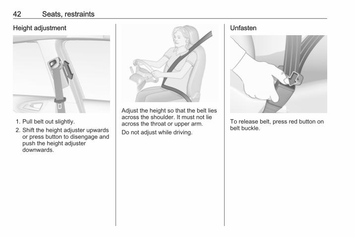
Height adjustment
1. Pull belt out slightly.2. Shift the height adjuster upwards
or press button to disengage andpush the height adjusterdownwards.
Adjust the height so that the belt liesacross the shoulder. It must not lieacross the throat or upper arm.Do not adjust while driving.
Unfasten
To release belt, press red button onbelt buckle.

Seats, restraints 43
Using the seat belt while pregnant
9 Warning
The lap belt must be positioned aslow as possible across the pelvisto prevent pressure on theabdomen.
Airbag systemThe airbag system consists of anumber of individual systemsdepending on the scope ofequipment.When triggered, the airbags inflatewithin milliseconds. They also deflateso quickly that it is often unnoticeableduring the collision.
9 Warning
If handled improperly the airbagsystems can be triggered in anexplosive manner.
NoticeThe airbag systems and beltpretensioner control electronics arelocated in the centre console area.Do not put any magnetic objects inthis area.Do not affix any objects onto theairbag covers and do not cover themwith other materials.Each airbag is triggered only once.Have deployed airbags replaced bya workshop. Furthermore, it may be
necessary to have the steeringwheel, the instrument panel, parts ofthe panelling, the door seals,handles and the seats replaced.Do not make any modifications tothe airbag system as this willinvalidate the vehicle type approval.
When the airbags inflate escaping hotgases may cause burns.
FaultIf there is a fault in the airbag system,the control indicator v illuminates anda message or a warning codeappears in the Driver InformationCentre. The system is notoperational.Have the cause of the fault remediedby a workshop.Control indicator for airbag systems3 90.

44 Seats, restraints
Child restraint systems on frontpassenger seat with airbagsystems
EN: NEVER use a rearward-facingchild restraint on a seat protected byan ACTIVE AIRBAG in front of it;DEATH or SERIOUS INJURY to theCHILD can occur.DE: Nach hinten gerichteteKindersitze NIEMALS auf einem Sitzverwenden, der durch einen davorbefindlichen AKTIVEN AIRBAGgeschützt ist, da dies den TOD oderSCHWERE VERLETZUNGEN DESKINDES zur Folge haben kann.
FR: NE JAMAIS utiliser un sièged'enfant orienté vers l'arrière sur unsiège protégé par un COUSSINGONFLABLE ACTIF placé devant lui,sous peine d'infliger desBLESSURES GRAVES, voireMORTELLES à l'ENFANT.ES: NUNCA utilice un sistema deretención infantil orientado haciaatrás en un asiento protegido por unAIRBAG FRONTAL ACTIVO. Peligrode MUERTE o LESIONES GRAVESpara el NIÑO.RU: ЗАПРЕЩАЕТСЯустанавливать детскоеудерживающее устройство лицомназад на сиденье автомобиля,оборудованном фронтальнойподушкой безопасности, еслиПОДУШКА НЕ ОТКЛЮЧЕНА! Этоможет привести к СМЕРТИ илиСЕРЬЕЗНЫМ ТРАВМАМРЕБЕНКА.NL: Gebruik NOOIT een achterwaartsgericht kinderzitje op een stoel meteen ACTIEVE AIRBAG ervoor, omDODELIJK of ERNSTIG LETSEL vanhet KIND te voorkomen.
DA: Brug ALDRIG en bagudvendtautostol på et forsæde med AKTIVAIRBAG, BARNET kan komme iLIVSFARE eller komme ALVORLIGTTIL SKADE.SV: Använd ALDRIG en bakåtvändbarnstol på ett säte som skyddas meden framförvarande AKTIV AIRBAG.DÖDSFALL eller ALLVARLIGASKADOR kan drabba BARNET.FI: ÄLÄ KOSKAAN sijoita taaksepäinsuunnattua lasten turvaistuintaistuimelle, jonka edessä onAKTIIVINEN TURVATYYNY, LAPSIVOI KUOLLA tai VAMMAUTUAVAKAVASTI.NO: Bakovervendtbarnesikringsutstyr må ALDRI brukespå et sete med AKTIVKOLLISJONSPUTE foran, da det kanføre til at BARNET utsettes forLIVSFARE og fare for ALVORLIGESKADER.PT: NUNCA use um sistema deretenção para crianças voltado paratrás num banco protegido com umAIRBAG ACTIVO na frente do
Seats, restraints 45
mesmo, poderá ocorrer a PERDA DEVIDA ou FERIMENTOS GRAVES naCRIANÇA.IT: Non usare mai un sistema disicurezza per bambini rivoltoall'indietro su un sedile protetto daAIRBAG ATTIVO di fronte ad esso:pericolo di MORTE o LESIONIGRAVI per il BAMBINO!EL: ΠΟΤΕ μη χρησιμοποιείτε παιδικόκάθισμα ασφαλείας με φορά προς ταπίσω σε κάθισμα που προστατεύεταιαπό μετωπικό ΕΝΕΡΓΟ ΑΕΡΟΣΑΚΟ,διότι το παιδί μπορεί να υποστείΘΑΝΑΣΙΜΟ ή ΣΟΒΑΡΟΤΡΑΥΜΑΤΙΣΜΟ.PL: NIE WOLNO montować fotelikadziecięcego zwróconego tyłem dokierunku jazdy na fotelu, przedktórym znajduje się WŁĄCZONAPODUSZKA POWIETRZNA.Niezastosowanie się do tegozalecenia może być przyczynąŚMIERCI lub POWAŻNYCHOBRAŻEŃ u DZIECKA.TR: Arkaya bakan bir çocuk emniyetsistemini KESİNLİKLE önünde birAKTİF HAVA YASTIĞI ilekorunmakta olan bir koltukta
kullanmayınız. ÇOCUK ÖLEBİLİRveya AĞIR ŞEKİLDEYARALANABİLİR.UK: НІКОЛИ не використовуйтесистему безпеки для дітей, щовстановлюється обличчям назад,на сидінні з УВІМКНЕНОЮПОДУШКОЮ БЕЗПЕКИ, інакше цеможе призвести до СМЕРТІ чиСЕРЙОЗНОГО ТРАВМУВАННЯДИТИНИ.HU: SOHA ne használjon hátrafelénéző biztonsági gyerekülést előlrőlAKTÍV LÉGZSÁKKAL védett ülésen,mert a GYERMEK HALÁLÁT vagyKOMOLY SÉRÜLÉSÉT okozhatja.HR: NIKADA nemojte koristiti sustavzadržavanja za djecu okrenut premanatrag na sjedalu s AKTIVNIMZRAČNIM JASTUKOM ispred njega,to bi moglo dovesti do SMRTI iliOZBILJNJIH OZLJEDA za DIJETE.SL: NIKOLI ne nameščajte otroškegavarnostnega sedeža, obrnjenega vnasprotni smeri vožnje, na sedež zAKTIVNO ČELNO ZRAČNOBLAZINO, saj pri tem obstajanevarnost RESNIH ali SMRTNIHPOŠKODB za OTROKA.
SR: NIKADA ne koristiti bezbednosnisistem za decu u kome su decaokrenuta unazad na sedištu saAKTIVNIM VAZDUŠNIMJASTUKOM ispred sedišta zato štoDETE može da NASTRADA ili da seTEŠKO POVREDI.MK: НИКОГАШ не користете детскоседиште свртено наназад наседиште заштитено со АКТИВНОВОЗДУШНО ПЕРНИЧЕ пред него,затоа што детето може ДА ЗАГИНЕили да биде ТЕШКО ПОВРЕДЕНО.BG: НИКОГА не използвайтедетска седалка, гледаща назад,върху седалка, която е защитеначрез АКТИВНА ВЪЗДУШНАВЪЗГЛАВНИЦА пред нея - може дасе стигне до СМЪРТ илиСЕРИОЗНО НАРАНЯВАНЕ наДЕТЕТО.RO: Nu utilizaţi NICIODATĂ un scaunpentru copil îndreptat spre partea dinspate a maşinii pe un scaun protejatde un AIRBAG ACTIV în faţa sa;acest lucru poate duce la DECESULsau VĂTĂMAREA GRAVĂ aCOPILULUI.

46 Seats, restraints
CS: NIKDY nepoužívejte dětskýzádržný systém instalovaný protisměru jízdy na sedadle, které jechráněno před sedadlem AKTIVNÍMAIRBAGEM. Mohlo by dojít kVÁŽNÉMU PORANĚNÍ nebo ÚMRTÍDÍTĚTE.SK: NIKDY nepoužívajte detskúsedačku otočenú vzad na sedadlechránenom AKTÍVNYM AIRBAGOM,pretože môže dôjsť k SMRTI aleboVÁŽNYM ZRANENIAM DIEŤAŤA.LT: JOKIU BŪDU nemontuokite atgalatgręžtos vaiko tvirtinimo sistemossėdynėje, prieš kurią įrengta AKTYVIORO PAGALVĖ, nes VAIKAS GALIŽŪTI arba RIMTAI SUSIŽALOTI.LV: NEKĀDĀ GADĪJUMĀneizmantojiet uz aizmuguri vērstubērnu sēdeklīti sēdvietā, kas tiekaizsargāta ar tās priekšā uzstādītuAKTĪVU DROŠĪBAS SPILVENU, jopretējā gadījumā BĒRNS var gūtSMAGAS TRAUMAS vai IET BOJĀ.ET: ÄRGE kasutage tahapoolesuunatud lapseturvaistet istmel, milleees on AKTIIVSE TURVAPADJAGA
kaitstud iste, sest see võibpõhjustada LAPSE SURMA võiTÕSISE VIGASTUSE.MT: QATT tuża trażżin għat-tfal lijħares lejn in-naħa ta’ wara fuq sitprotett b’AIRBAG ATTIV quddiemu;dan jista’ jikkawża l-MEWT jewĠRIEĦI SERJI lit-TFAL.Beyond the warning required byECE R94.02, for safety reasons aforward-facing child restraint systemmust only be used subject to theinstructions and restrictions in thetables 3 51.The airbag label is located on bothsides of the front passenger sun visor.Airbag deactivation 3 48.
Front airbag systemThe front airbag system consists ofone airbag in the steering wheel andone in the instrument panel on thefront passenger side. The location isidentified by the word AIRBAG.
The front airbag system is triggered inthe event of a front-end impact of acertain severity. The ignition must beswitched on.

Seats, restraints 47
The inflated airbags cushion theimpact, thereby reducing the risk ofinjury to the upper body and head ofthe front seat occupantsconsiderably.
9 Warning
Optimum protection is onlyprovided when the seat is in theproper position.Seat position 3 36.Keep the area in which the airbaginflates clear of obstructions.Fit the seat belt correctly andengage securely. Only then is theairbag able to protect.
Side airbag system
The side airbag system consists of anairbag in each front seat backrest.The location is identified by the wordAIRBAG.The side airbag system is triggered inthe event of a side impact of a certainseverity. The ignition must beswitched on.
The inflated airbags cushion theimpact, thereby reducing the risk ofinjury to the upper body and pelvis inthe event of a side-on collisionconsiderably.
9 Warning
Keep the area in which the airbaginflates clear of obstructions.
NoticeOnly use protective seat covers thathave been approved for the vehicle.Be careful not to cover the airbags.

48 Seats, restraints
Curtain airbag systemThe curtain airbag system consists ofan airbag in the roof frame on eachside. The location is identified by theword AIRBAG on the roof pillars.The curtain airbag system is triggeredin the event of a side-on impact of acertain severity. The ignition must beswitched on.
The inflated airbags cushion theimpact, thereby reducing the risk ofinjury to the head in the event of aside-on impact considerably.
9 Warning
Keep the area in which the airbaginflates clear of obstructions.The hooks on the handles in theroof frame are only suitable forhanging up light articles ofclothing, without coat hangers. Donot keep any items in theseclothes.
Airbag deactivationThe front passenger airbag systemmust be deactivated for a childrestraint system on the passengerseat according to the instructions inthe tables 3 51.The other airbag systems, the beltpretensioners and all driver airbagsystems will remain active.
Use the ignition key to choose theswitch position:*OFF : front passenger airbag is
deactivated and will notinflate in the event of acollision. Control indicator*OFF illuminatescontinuously in the centreconsole
VON : front passenger airbag isactive

Seats, restraints 49
9 Danger
Deactivate passenger airbag onlyin combination with the use of achild restraint system, subject tothe instructions and restrictions inthe tables 3 51.Otherwise, there is a risk of fatalinjury for a person occupying aseat with a deactivated frontpassenger airbag.
If control indicator V illuminates forapprox. 60 seconds after the ignitionis switched on, the front passengerairbag system will inflate in the eventof a collision.
If both control indicators areilluminated at the same time, there isa system failure. The status of thesystem is not discernible, thereforeno person is allowed to occupy thefront passenger seat. Contact aworkshop immediately.Change status only when the vehicleis stopped with the ignition off.Status remains until the next change.Control indicator for airbagdeactivation 3 91.
Child restraintsChild restraint systemsWe recommend Vauxhall childrestraint systems which are tailoredspecifically to the vehicle.The following child restraints arerecommended for the followingweight classes:● Group 0, Group 0+
Maxi Cosi Cabriofix plus Easyfix,for children up to 13 kg
● Group IVAUXHALL Duo, for childrenfrom 13 kg to 18 kg in this group
When a child restraint system is beingused, pay attention to the followingusage and installation instructionsand also those supplied with the childrestraint system.Check local laws and regulations formandatory use of child restraintsystems. In some countries, the useof child restraint systems is forbiddenon certain seats.

50 Seats, restraints
9 Danger
If using a rear-facing child restraintsystem on the front passengerseat, the airbag system for thefront passenger seat must bedeactivated. This also applies tocertain forward-facing childrestraint systems as indicated inthe tables 3 51.
Airbag deactivation 3 48.Airbag label 3 43.The rear seats are the mostconvenient location to fasten a childrestraint system.Children should travel facingrearwards in the vehicle as long aspossible. This ensures that the child'sbackbone, which is still very weak, isunder less strain in the event of anaccident.
Selecting the right systemOnly use suitable restraint systems,e.g. those that comply with validUN ECE regulations.
Ensure that the child restraint systemto be installed is compatible with thevehicle type. Refer to the tables onthe following pages, the instructionssupplied with the child restraintsystem and the vehicle type list ofnon-universal child restraint systems.Ensure that the mounting location ofthe child restraint system within thevehicle is correct, see followingtables.Allow children to enter and exit thevehicle only on the side facing awayfrom the traffic.When the child restraint system is notin use, secure the seat with a seat beltor remove it from the vehicle.Child restraint systems could befastened with ISOFIX mountingbrackets, Top-tether if available,and/or a three-point seat belt. Referto the following tables.NoticeDo not affix anything on the childrestraint systems and do not coverthem with any other materials.
A child restraint system which hasbeen subjected to stress in anaccident must be replaced.

Seats, restraints 51
Child restraint installation locationsPermissible options for fastening a child restraint system with a three-point seat belt
Weight and age classOn front passenger seat
On rear outboard seats On rear centre seatactivated airbag deactivated airbag
Group 0: up to 10 kgor approx. 10 months
X U1,2 U/L3 X
Group 0+: up to 13 kgor approx. 2 years
X U1,2 U/L3 X
Group I: 9 to 18 kgor approx. 8 months to 4 years
X U1,2 U/L3,4 X
Group II: 15 to 25 kgor approx. 3 to 7 years
U1,2 X U/L3,4 X
Group III: 22 to 36 kgor approx. 6 to 12 years
U1,2 X U/L3,4 X
U : universal suitability in conjunction with three-point seat beltL : suitable for particular child restraint systems of the 'specific-vehicle', 'restricted' or 'semi-universal' categories. The
child restraint system must be approved for the specific vehicle type (refer to the vehicle type list of the child restraintsystem)
X : no child restraint system permitted in this weight class1 : move seat forwards as far as necessary and adjust seat backrest inclination as far as necessary to a vertical position
to ensure that the belt runs forwards from the upper anchorage point

52 Seats, restraints2 : move seat height adjustment upwards as far as necessary and adjust seat backrest inclination as far as necessary
to a vertical position to ensure that the belt is tight on the buckle side3 : move the respective front seat ahead of the child restraint system forwards as far as necessary4 : adjust the respective backrest to the rearmost position 3 67, adjust the respective headrest as necessary or remove
if required 3 35
Permissible options for fitting an ISOFIX child restraint system
Weight class Size class FixtureOn front passenger seat5 On rear
outboard seatsOn rearcentre seatactivated airbag deactivated airbag
Group 0: up to 10 kgor approx. 10 months
E ISO/R1 X IL IL3 X
Group 0+: up to 13 kgor approx. 2 years
E ISO/R1 X IL IL3 X
D ISO/R2 X IL IL3 X
C ISO/R3 X IL IL3 X
Group I: 9 to 18 kgor approx. 8 months to 4 years
D ISO/R2 X IL IL3,4 X
C ISO/R3 X IL IL3,4 X
B ISO/F2 X IL/IUF IL, IUF3,4 X
B1 ISO/F2X X IL/IUF IL, IUF3,4 X
A ISO/F3 X IL/IUF IL, IUF3,4 X
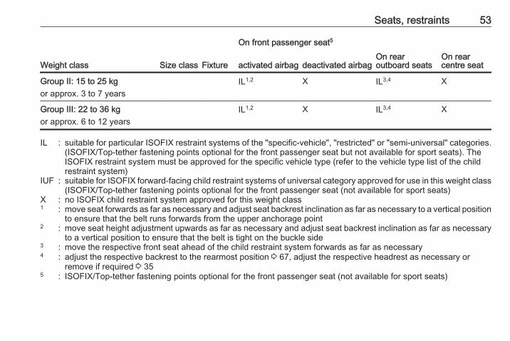
Seats, restraints 53
Weight class Size class Fixture
On front passenger seat5
On rearoutboard seats
On rearcentre seatactivated airbag deactivated airbag
Group II: 15 to 25 kgor approx. 3 to 7 years
IL1,2 X IL3,4 X
Group III: 22 to 36 kgor approx. 6 to 12 years
IL1,2 X IL3,4 X
IL : suitable for particular ISOFIX restraint systems of the "specific-vehicle", "restricted" or "semi-universal" categories.(ISOFIX/Top-tether fastening points optional for the front passenger seat but not available for sport seats). TheISOFIX restraint system must be approved for the specific vehicle type (refer to the vehicle type list of the childrestraint system)
IUF : suitable for ISOFIX forward-facing child restraint systems of universal category approved for use in this weight class(ISOFIX/Top-tether fastening points optional for the front passenger seat (not available for sport seats)
X : no ISOFIX child restraint system approved for this weight class1 : move seat forwards as far as necessary and adjust seat backrest inclination as far as necessary to a vertical position
to ensure that the belt runs forwards from the upper anchorage point2 : move seat height adjustment upwards as far as necessary and adjust seat backrest inclination as far as necessary
to a vertical position to ensure that the belt is tight on the buckle side3 : move the respective front seat ahead of the child restraint system forwards as far as necessary4 : adjust the respective backrest to the rearmost position 3 67, adjust the respective headrest as necessary or
remove if required 3 355 : ISOFIX/Top-tether fastening points optional for the front passenger seat (not available for sport seats)

54 Seats, restraints
ISOFIX size class and seat deviceA – ISO/F3 : forward-facing child restraint system for children of maximum size in the weight class 9 to 18 kgB – ISO/F2 : forward-facing child restraint system for smaller children in the weight class 9 to 18 kgB1 – ISO/F2X : forward-facing child restraint system for smaller children in the weight class 9 to 18 kgC – ISO/R3 : rear-facing child restraint system for children of maximum size in the weight class up to 18 kgD – ISO/R2 : rear-facing child restraint system for smaller children in the weight class up to 18 kgE – ISO/R1 : rear-facing child restraint system for young children in the weight class up to 13 kg

Seats, restraints 55
ISOFIX child restraintsystemsFasten vehicle-approved ISOFIXchild restraint systems to the ISOFIXmounting brackets. Specific vehicleISOFIX child restraint systempositions are marked in the table byIL.The vehicle is equipped with guides inthe backrests to support theinstallation of the child restraintsystem.
ISOFIX child restraint systems onrear seats
ISOFIX mounting brackets on therear seats are indicated by theISOFIX logo on the backrest.Open the flaps of the guides beforemounting a child restraint system.After removing the child restraintsystem, close the flaps.
ISOFIX child restraint systems onfront passenger seat
Place the child restraint system in thecentre of the seat and pushbackwards. Make sure that the childrestraint system is engaged properly.
Top-tether fastening eyesIn addition to the ISOFIX mounting,fasten the Top-tether strap to theTop-tether fastening eyes.ISOFIX child restraint systems ofuniversal category positions aremarked in the table by IUF.
Top-tether fastening eye on rearseatsThe vehicle has two fastening eyeson the back of the rear seats.Top-tether fastening eyes are markedwith the symbol : for a child seat.

56 Seats, restraints
Top-tether fastening eye on frontpassenger seatAn additional fastening point islocated on the passenger seat rail inthe rear foot well.

Storage 57
Storage
Storage compartments ................ 57Glovebox ................................... 57Cupholders ................................ 57Front storage ............................. 58Underseat storage ..................... 59Rear carrier system ................... 59
Load compartment ....................... 67Load compartment cover ........... 69Rear floor storage cover ............ 70Lashing eyes ............................. 71Warning triangle ........................ 72First aid kit ................................. 72
Roof rack system ......................... 72Roof rack ................................... 72
Loading information ..................... 73
Storage compartments
9 Warning
Do not store heavy or sharpobjects in the storagecompartments. Otherwise, thestorage compartment lid couldopen and vehicle occupants couldbe injured by objects being thrownaround in the event of hardbraking, a sudden change indirection or an accident.
Glovebox
Pull lever to open the glovebox cover.The glovebox features a coin holderand an adapter for the locking wheelbolts.The glovebox should be closed whilstdriving.
Cupholders
Cupholders are located in the centreconsole.

58 Storage
The pockets in the doors aredesigned to carry bottles.
Additional bottleholders are located inthe rear side panels.
Flexible cupholder strap
A movable rubber strap is located inthe storage compartment in front ofthe gear selector lever. Pull out thestrap to fix a cup or ashtray.
Front storage
Storage compartments are locatedbelow the light switch, in the centreconsole, in the door pockets and inthe side panels near the rear seats.

Storage 59
Underseat storage
Lift at recessed edge and pull out.Maximum load: 1.5 kg. To close, pushin and engage.
Rear carrier system
The rear carrier system (Flex-Fixsystem) allows bicycles to beattached to a pull-out carrierintegrated into the vehicle floor. Thetransportation of other objects is notpermitted.The maximum load of the rear carriersystem is 40 kg. The maximum loadper bicycle is 20 kg.The wheelbase of a bicycle must notexceed 1.2 metres. Otherwise thesecure fastening of a bicycle is notpossible.If not in use, the carrier system can beslid back into the vehicle floor.
There must not be any objects on thebicycles that could become looseduring transportation.
Caution
Do not attach bicycles with carbonpedal cranks to bicycle carriers.The bicycles may get damaged.
ExtendingOpen the tailgate.
9 Warning
No people may remain in theextension zone of the rear carriersystem, risk of injury.

60 Storage
Pull release lever up. The systemdisengages and travels quickly out ofthe bumper.
Completely pull out the rear carriersystem until you hear it engage.Ensure that it is not possible to pushin the rear carrier system withoutpulling the release lever again.
9 Warning
It is only permissible to fit objectsto the rear carrier system if thesystem has been correctlyengaged. If the rear carrier systemwill not engage correctly, do not fitobjects to the system and slide thesystem back. Seek the assistanceof a workshop.
Install the tail lamps
First remove the rear (1), then thefront (2) tail lamp from the recesses.

Storage 61
Open out the lamp support on theback of the tail lamp completely untilit engages.
Push the clamping lever down andpush the lamp support into theretainer until it engages.Perform this procedure for both taillamps.
Check the cable and lamp position toensure these are correctly installedand are securely located.
Lock the rear carrier system
Swivel the left clamping lever (1) first,followed by the right clamping lever(2) until they stop. Both clampinglevers must point backwards,otherwise safe functionality is notguaranteed.NoticeClose the tailgate.
Unfold pedal crank recesses
Fold one or both pedal crankrecesses upwards until the diagonalsupport engages.

62 Storage
Remove the pedal crank mounts fromthe pedal crank recesses.
Adapting the rear carrier systemto a bicycle
Press the release lever and withdrawthe wheel recesses.
Push the release lever on the strapretainer and remove the strapretainer.
Prepare the bicycle forattachment
NoticeThe maximum width for the pedalcrank is 38.3 mm and the maximumdepth is 14.4 mm.
Rotate the left pedal (without a chaincog) vertically downwards. The pedalon the left pedal crank must behorizontal.The front bicycle must have its frontwheel facing left.The rear bicycle must have its frontwheel facing right.

Storage 63
Attaching a bicycle to the rearcarrier system
With the rotary lever on the pedalcrank recess, roughly adapt theadjustable pedal crank unit to theprotrusion of the pedal crank.If the bicycle has straight pedalcranks, unscrew the pedal crank unitcompletely (position 5).
If the bicycle has curved pedalcranks, screw in the pedal crank unitall the way (position 1).
Put on the bicycle. The pedal crankhere must be placed in the pedalcrank recess opening as shown in theillustration.
Caution
Make sure that the pedal does nottouch the surface of the rear endcarrier. Otherwise the cranksetmight be damaged during thetransport.
Insert pedal crank mount into outerrail of each pedal crank recess fromabove and slide downwards until atleast underneath the notching.
64 Storage
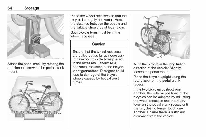
Attach the pedal crank by rotating theattachment screw on the pedal crankmount.
Place the wheel recesses so that thebicycle is roughly horizontal. Here,the distance between the pedals andthe tailgate should be at least 5 cm.Both bicycle tyres must be in thewheel recesses.
Caution
Ensure that the wheel recessesare pulled out as far as necessaryto have both bicycle tyres placedin the recesses. Otherwise ahorizontal mounting of the bicycleis not guaranteed. Disregard couldlead to damage of the bicyclewheels caused by hot exhaustfumes.
Align the bicycle in the longitudinaldirection of the vehicle: Slightlyloosen the pedal mount.Place the bicycle upright using therotary lever on the pedal crankrecess.If the two bicycles obstruct oneanother, the relative positions of thebicycles can be adapted by adjustingthe wheel recesses and the rotarylever on the pedal crank recess untilthe bicycles no longer touch oneanother. Ensure there is sufficientclearance from the vehicle.

Storage 65
Tighten the attachment screw for thepedal bearing mount to its maximumpoint by hand.Secure both bicycle wheels to wheelrecesses using strap retainers.Check the bicycle to ensure it issecure.
Caution
Ensure gap between bicycle andvehicle is at least 5 cm. Ifnecessary, loosen handlebar andswivel sideways.
The settings for the wheel recessesand on the rotary lever on the pedalcrank recess should be noted andsaved for each bicycle. Correctpresetting will facilitate refitting of thebicycle.NoticeIt is recommended to attach awarning sign at the rearmost bicycleto increase visibility.
Removing a bicycle from the rearcarrier system
Undo strap retainers on both bicycletyres.
Hold on to the bicycle, loosen theattachment screw for the pedalbearing mount, then lift the pedalbearing mount to remove it.
Retracting the rear carrier system
Push the pedal crank mounts into thepedal crank recess as shown in theillustration.

66 Storage
Insert the strap retainer and pulltightly downwards as far as possible.
Press release lever and slide in wheelrecesses all the way as far as they willgo.
Disengage the locking lever on thediagonal support and fold both pedalcrank recesses down.
9 Warning
Risk of pinching.
Swivel first the right clamping lever(1) forwards, followed by the leftclamping lever (2), until they can beengaged in their respective recesses.

Storage 67
Push the clamping lever down andpull both lamp supports out of therecesses.
Fold in the lamp supports on thebacks of the tail lamps.First place the front tail lamp (1), thenthe rear tail lamp (2) in the recessesand push down as far as possible.Push cables all the way into all guidesin order to prevent damage.Open the tailgate.
Push the release lever up and hold.Lift the system slightly and push it intothe bumper until it engages.Release lever must return to originalposition.
9 Warning
If the system cannot be correctlyengaged, please seek theassistance of a workshop.
Load compartment
Load compartment extensionThe rear backrest can be locked intwo positions. When transportingbulky items, lock in an uprightposition.
Split backrestPull the release handle on therelevant side, pull the backrestforwards to the vertical position andengage.Single-unit backrest

68 Storage
Pull the release handle on both sides,pull the backrest forwards to thevertical position and engage.When unlocking, a red markingappears next to the release lever. Thebackrest is properly engaged whenthe red marks on both sides near therelease lever are no longer visible.
Folding down rear backrestsRemove load compartment cover asnecessary.Push head restraints down bypressing the catch.
Guide the seat belts through sidesupports to protect them againstdamage. When folding the backrest,pull the seat belts along with it.Split backrestPull the release handle on therelevant side and fold it down onto theseat cushion.Single-unit backrestPull the release handle on both sidesand fold it down onto the seatcushion.
If the vehicle is to be loaded via a reardoor, take the seat belt out of the seatbackrest guide and insert the latchplate in the recess as shown in theillustration.To fold up, raise the backrest andguide it into an upright position until itengages audibly.Ensure that the seat belts of theoutboard seats are placed in thecorresponding belt guides.
The backrest is properly engagedwhen the red marks on both sidesnear the release lever are no longervisible.

Storage 69
9 Warning
Only drive the vehicle when thebackrests are securely locked intoposition. Otherwise there is a riskof personal injury or damage to theload or vehicle in the event of hardbraking or a collision.
The seat belt of the centre seat couldbe blocked when the backrest isfolded up too quickly. To unlock theretractor, push in the seat belt or pullit out by approx. 20 mm then release.
Load compartment coverDo not place any objects on the cover.
3-door/5-door hatchback
Removing
Unhook retaining straps from tailgate.Lift cover at the rear and push itupwards at the front.Remove the cover.
StowingWhen the load compartment is fullyloaded, stow the load compartmentcover on the rear seats or removefrom vehicle.
FittingEngage cover in side guides and folddownwards. Attach retaining straps totailgate.
Delivery vanThe load compartment cover consistsof four segments which can beindividually removed and inserted.
Removing
To remove rear cover, unhookretaining straps from tailgate.Lift cover at the rear and push itupwards at the front. Remove thecover.

70 Storage
To remove the three other segments(order 1 to 3) lift at the rear,disengage, twist and remove.
FittingInstall the segments in the order 3 to1. Engage segments in recesses atthe side.The segments overlap at theconnecting points when they areclosed.To install rear cover, engage cover inside guides and fold downwards.Attach retaining straps to tailgate.
Rear floor storage coverRear floor cover
Lift up rear floor cover to gain accessto emergency breakdown equipment.Tools 3 209.In models with a tyre repair kit on theright side in the load compartment,the spare wheel recess may be usedas an additional stowagecompartment. Tyre repair kit 3 217.
Double load-bay floorThe double load-bay floor can beinserted in the load compartment intwo positions:
● directly above the cover for thespare wheel recess or the floorcover
● or in the upper openings in theload compartment
To remove, lift the load-bay floorusing the recess and pull backwards.To insert, push the load-bay floorforwards in the corresponding guide,then lower.If mounted in the upper position, thespace between the load-bay floor andthe spare wheel well cover can beused as a stowage compartment.
Storage 71
In this position, if the rear seatbackrests are folded forwards, analmost completely flat load bay iscreated.The double load-bay floor is able towithstand a load of no more than100 kg. In the lower position, thedouble load-bay floor is able towithstand the maximum permissibleload.
General hint
9 Warning
For safety reasons, stow all partsin the load compartment in itsposition, always drive with aclosed rear floor cover and, ifpossible, with folded up rearbackrests.Otherwise, vehicle occupantscould be injured by objects beingthrown around in the event of hardbraking, a sudden change indirection or an accident.
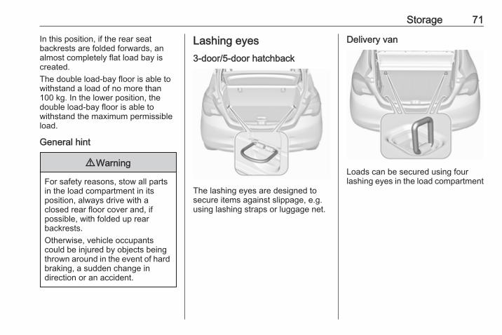
Lashing eyes3-door/5-door hatchback
The lashing eyes are designed tosecure items against slippage, e.g.using lashing straps or luggage net.
Delivery van
Loads can be secured using fourlashing eyes in the load compartment

72 Storage
Warning triangle
The warning triangle is stowed in theload compartment below the tailgate.
First aid kit
Stow the first-aid kit in thecompartment in the left wall of theload compartment.To open the compartment, disengagecover and open it.
Roof rack systemRoof rackFor safety reasons and to avoiddamage to the roof, the vehicleapproved roof rack system isrecommended. For furtherinformation contact your workshop.Follow the installation instructionsand remove the roof rack when not inuse.Fitting on model without sunroof
Push covers for concealing roof rackmounts down and push backwardswith a valve cap key 3 209.

Storage 73
Fitting on model with sunroof
Disengage covers concealing roofrack mounts by pushing sliders indirection of arrow and removeupwards. To close roof rack mounts,first insert covers at front and engagesliders at rear.Attach roof rack at appropriate points,see enclosed roof rack systeminstructions.
Loading information
● Heavy objects in the loadcompartment should be placedagainst the seat backrests.Ensure that the backrests aresecurely engaged. If objects canbe stacked, heavier objectsshould be placed at the bottom.
● Secure objects with lashingstraps attached to the lashingeyes 3 71.
● Use the hook at the right sidewallof the load compartment forhanging up carrier bags.Maximum load: 5 kg.
● Secure loose objects in the loadcompartment to prevent themfrom sliding.
● When transporting objects in theload compartment, the backrestsof the rear seats must not beangled forward.
● Do not allow the load to protrudeabove the upper edge of thebackrests.
● Do not place any objects on theload compartment cover or theinstrument panel, and do notcover the sensor on top of theinstrument panel.
● The load must not obstruct theoperation of the pedals, parkingbrake and gear selector lever, orhinder the freedom of movementof the driver. Do not place anyunsecured objects in the interior.
● Do not drive with an open loadcompartment.

74 Storage
9 Warning
Always make sure that the load inthe vehicle is securely stowed.Otherwise objects can be thrownaround inside the vehicle andcause personal injury or damageto the load or vehicle.
● The payload is the differencebetween the permitted grossvehicle weight (see identificationplate 3 238) and the EC kerbweight.To calculate the payload, enterthe data for your vehicle in theweights table at the front of thismanual.The EC kerb weight includesweights for the driver (68 kg),luggage (7 kg) and all fluids (fueltank 90% full).Optional equipment andaccessories increase the kerbweight.
● Driving with a roof load increasesthe sensitivity of the vehicle tocross-winds and has a
detrimental effect on vehiclehandling due to the vehicle'shigher centre of gravity.Distribute the load evenly andsecure it properly with retainingstraps. Adjust the tyre pressureand vehicle speed according tothe load conditions. Check andretighten the straps frequently.Do not drive faster than 75 mph.The permissible roof load is75 kg. The roof load is thecombined weight of the roof rackand the load.

Instruments and controls 75
Instruments andcontrols
Controls ....................................... 76Steering wheel adjustment ........ 76Steering wheel controls ............. 76Heated steering wheel ............... 76Horn ........................................... 77Windscreen wiper/washer ......... 77Rear window wiper/washer ....... 79Outside temperature .................. 79Clock ......................................... 80Power outlets ............................. 82Cigarette lighter ......................... 82Ashtrays .................................... 83
Warning lights, gauges and indi‐cators ........................................... 83
Instrument cluster ...................... 83Speedometer ............................. 83Odometer .................................. 83Trip odometer ............................ 83Tachometer ............................... 84Fuel gauge ................................ 85Fuel selector .............................. 85Engine coolant temperaturegauge ....................................... 86
Service display .......................... 86
Control indicators ...................... 87Turn signal ................................. 89Seat belt reminder ..................... 90Airbag and belt tensioners ......... 90Airbag deactivation .................... 91Charging system ....................... 91Malfunction indicator light .......... 91Service vehicle soon ................. 91Brake and clutch system ........... 92Operate pedal ............................ 92Antilock brake system (ABS) ..... 92Gear shifting .............................. 92Power steering .......................... 92Lane departure warning ............ 92Ultrasonic parking assist ........... 93Electronic Stability Control off . . . 93Electronic Stability Control andTraction Control system ........... 93
Traction Control system off ....... 93Preheating ................................. 93Diesel particle filter .................... 93Tyre pressure monitoringsystem ...................................... 94
Engine oil pressure .................... 94Low fuel ..................................... 94Immobiliser ................................ 94Reduced engine power ............. 94Autostop .................................... 95Exterior light .............................. 95High beam ................................. 95
High beam assist ....................... 95Fog light ..................................... 95Rear fog light ............................. 95Cruise control ............................ 95Vehicle detected ahead ............. 95Speed limiter ............................. 95Traffic sign assistant .................. 95Door open .................................. 95
Information displays ..................... 96Driver Information Centre .......... 96Colour-Info-Display .................. 100Graphic-Info-Display ................ 101
Vehicle messages ...................... 102Warning chimes ....................... 104Battery voltage ........................ 104
Vehicle personalisation .............. 105OnStar ....................................... 108

76 Instruments and controls
ControlsSteering wheel adjustment
Unlock lever, adjust steering wheel,then engage lever and ensure it isfully locked.Do not adjust steering wheel unlessvehicle is stationary and steeringwheel lock has been released.
Steering wheel controls
Cruise control, Speed limiter,Forward collision alert setting,Infotainment system and a connectedmobile phone can be operated via thecontrols on the steering wheel.Driver assistance systems 3 153.Further information is available in theInfotainment manual.
Heated steering wheel
Activate heating by pressing *.Activation is indicated by the LED inthe button.

Instruments and controls 77
The highlighted grip areas of thesteering wheel are heated quickerand to a higher temperature than theother areas.Heating is operational when theengine is running and during anAutostop.Stop-start system 3 135.
Horn
Press j.
Windscreen wiper/washerWindscreen wiper
HI : fastLO : slowINT : interval wiping
orautomatic wiping with rainsensor
OFF : off
For a single wipe when thewindscreen wiper is off, press thelever down to position 1x.Do not use if the windscreen is frozen.Switch off in car washes.
Adjustable wiper interval
Wiper lever in position INT.Turn the adjuster wheel to adjust thedesired wipe interval:short interval : turn adjuster
wheel upwardslong interval : turn adjuster
wheel downwards

78 Instruments and controls
Automatic wiping with rain sensor
INT : automatic wiping with rainsensor
The rain sensor detects the amount ofwater on the windscreen andautomatically regulates the frequencyof the windscreen wiper.If the wiper frequency is above20 seconds, the wiper arm movesslightly down to the park position.
Adjustable sensitivity of the rainsensor
Turn the adjuster wheel to adjust thesensitivity:low sensitivity : turn adjuster
wheel downwardshigh sensitivity : turn adjuster
wheel upwards
Keep the sensor free from dust, dirtand ice.
Windscreen washer

Instruments and controls 79
Pull lever. Washer fluid is sprayedonto the windscreen and the wiperwipes a few times.Washer fluid 3 193
Rear window wiper/washer
Press the rocker switch to activate therear window wiper:upper position : continuous
operationlower position : intermittent
operationmiddle position : off
Push lever. Washer fluid is sprayedonto the rear window and the wiperwipes a few times.Do not use if the rear window isfrozen.Switch off in car washes.The rear window wiper comes onautomatically when the windscreenwiper is switched on and reverse gearis engaged.Activation or deactivation of thisfunction can be changed in the menuSettings in the Info-Display.Washer fluid 3 193Vehicle personalisation 3 105.
Outside temperatureA drop in temperature is indicatedimmediately and a rise in temperatureafter a time delay. Temperaturesbelow 3 °C flash on the display.
Illustration shows Graphic-Info-Display.

80 Instruments and controls
Illustration shows Colour-Info-Display.Uplevel display
If outside temperature drops to 3 °C,a warning message is displayed in theDriver Information Centre.
9 Warning
The road surface may already beicy even though the displayindicates a few degrees above 0°C.
ClockGraphic-Info DisplayPress CONFIG to open the Settingsmenu.Scroll through the list and select themenu item Time Date to display therespective submenu.
NoticeFor a detailed description of menuoperation, refer to the Infotainmentmanual.
Set time
Press the MENU-TUNE knob to enterthe Set time submenu.Turn the MENU-TUNE knob tochange the current value of the firstsetting.Press the MENU-TUNE knob toconfirm the set value.The cursor then switches to the nextvalue. If all values are set, you areautomatically returned to the nexthigher menu level.

Instruments and controls 81
Set date
Press the MENU-TUNE knob to enterthe Set date submenu.Turn the MENU-TUNE knob tochange the current value of the firstsetting.Press the MENU-TUNE knob toconfirm the set value.The cursor then switches to the nextvalue. If all values are set, you areautomatically returned to the nexthigher menu level.
Set time formatTo switch between the availableoptions, repeatedly press theMENU-TUNE knob.
Set date formatTo switch between the availableoptions, repeatedly press theMENU-TUNE knob.
RDS clock synchronizationThe RDS signal of most VHFtransmitters automatically sets thetime. RDS time synchronisation cantake a few minutes. Sometransmitters do not send a correcttime signal. In such cases, it isrecommended to switch off theautomatic time synchronisation.To switch between the options Onand Off, repeatedly press theMENU-TUNE knob.
Colour-Info DisplayPress ; and then select theSettings screen button.Select Time & date settings to displaythe respective submenu.
NoticeFor a detailed description of menuoperation, refer to the Infotainmentmanual.
Set time formatTo select the desired time format, tapon the screen buttons 12 h or 24 h.
Set date formatTo select the desired date format, tapon the < and > screen buttons andchoose between the availableoptions.

82 Instruments and controls
Set time and date
To adjust the time and date settings,tap on the H and I screen buttons.
RDS clock synchronizationThe RDS signal of most VHFtransmitters automatically sets thetime. RDS time synchronisation cantake a few minutes. Sometransmitters do not send a correcttime signal. In such cases, it isrecommended to switch off theautomatic time synchronisation.To activate or deactivate RDS clocksynchronization, tap on the screenbuttons On or Off.
Power outlets
A 12 Volt power outlet is located in thecentre console.Do not exceed the maximum powerconsumption of 120 watts.With ignition off, the power outlet isdeactivated. Additionally, the poweroutlet is deactivated in the event oflow vehicle battery voltage.Electrical accessories that areconnected must comply with theelectromagnetic compatibilityrequirements laid down inDIN VDE 40 839.
Do not connect any current-deliveringaccessories, e.g. electrical chargingdevices or batteries.Do not damage the outlet by usingunsuitable plugs.Stop-start system 3 135.
Cigarette lighter
The cigarette lighter is located in thecentre console.Press in cigarette lighter. It switchesoff automatically once the element isglowing. Pull out lighter.

Instruments and controls 83
Ashtrays
Caution
To be used only for ash and not forcombustible rubbish.
The portable ashtray can be placed inthe cupholders.
Warning lights, gaugesand indicatorsInstrument clusterThe needles of the instruments brieflyrotate to the end position when theignition is switched on.
Speedometer
Indicates vehicle speed.
Odometer
The bottom line displays the recordeddistance in miles.
Trip odometerThe recorded distance is displayedsince the last reset.Trip odometer counts up to9999 miles and then restarts at 0.

84 Instruments and controls
Midlevel display
To reset, press SET/CLR on the turnsignal lever for a few seconds3 96.
Uplevel display
Two trip odometers are selectable fordifferent trips.Select menu Trip/Fuel InformationMenu ; by pressing Menu on theturn signal lever. Turn adjuster wheelon turn signal lever and select Trip 1or Trip 2. Each trip odometer can bereset separately by pressingSET/CLR on the turn signal lever fora few seconds on the respectivemenu.
Tachometer
Displays the engine speed.Drive in a low engine speed range foreach gear as much as possible.
Caution
If the needle is in the red warningzone, the maximum permittedengine speed is exceeded. Engineat risk.

Instruments and controls 85
Fuel gauge
Number of LEDs displays the level inthe fuel tank.8LEDs
: fuel tank is full.The arrow indicates thevehicle side where the fuelfiller flap is located.
During liquid gas operation, the levelin the gas tank is displayed.Control indicator Y illuminates if thelevel in the tank is low. Refuelimmediately if it flashes.
During liquid gas operation, thesystem automatically switches over topetrol operation when gas tanks areempty 3 85.Never run the fuel tank dry.Because of the fuel remaining in thetank, the top-up quantity may be lessthan the specified tank capacity.
Fuel selector
Press LPG to switch between petroland liquid gas operation. The LED inthe button shows the currentoperating mode.
LED off : petrol operationLEDflashes
: checking conditions forfuel transition to liquidgas operation.Illuminates if conditionsare fulfilled.
LED illu‐minates
: liquid gas operation
LEDflashesfivetimesandextin‐guishes
: liquid gas tank is emptyor failure in liquid gassystem. A message isdisplayed in the DriverInformation Centre.
As soon as the liquid gas tank isempty, petrol operation isautomatically engaged until theignition is switched off.Fuel for liquid gas operation 3 176.

86 Instruments and controls
Engine coolant temperaturegauge
Number of LEDs displays the coolanttemperature.up to 3 LEDs : engine operating
temperature notyet reached
4 to 6 LEDs : normal operatingtemperature
more than 6LEDs
: temperature toohigh
Caution
If engine coolant temperature istoo high, stop vehicle, switch offengine. Danger to engine. Checkcoolant level.
Service displayThe engine oil life system lets youknow when to change the engine oiland filter. Based on drivingconditions, the interval at which anengine oil and filter change will beindicated can vary considerably.To display the remaining engine oillife duration use turn signal leverbuttons:
Press MENU to select the VehicleInformation Menu ?.Turn the adjuster wheel to selectRemaining Oil Life.

Instruments and controls 87
The remaining engine oil life durationis displayed in percent in the DriverInformation Centre.
ResetPress SET/CLR on turn signal leverfor several seconds to reset. Theremaining engine oil life durationmenu must be active. Switch onignition, but not the engine.The system must be reset every timethe engine oil is changed to ensureproper functionality. Seek theassistance of a workshop.
Next serviceWhen the system has calculated thatengine oil life has diminished, awarning message appears in theDriver Information Centre. Haveengine oil and filter changed by aworkshop within one week or300 miles (whichever occurs first).Driver Information Centre 3 96.Service information 3 234.
Control indicatorsThe control indicators described arenot present in all vehicles. Thedescription applies to all instrumentversions.Depending on the equipment, theposition of the control indicators mayvary. When the ignition is switchedon, most control indicators willilluminate briefly as a functionalitytest.The control indicator colours mean:red : danger, important reminderyellow : warning, information, faultgreen : confirmation of activationblue : confirmation of activationwhite : confirmation of activation

88 Instruments and controls
Control indicators in the instrument cluster
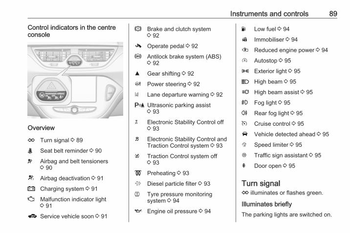
Instruments and controls 89
Control indicators in the centreconsole
Overview
O Turn signal 3 89
X Seat belt reminder 3 90
v Airbag and belt tensioners3 90
V Airbag deactivation 3 91
p Charging system 3 91
Z Malfunction indicator light3 91
g Service vehicle soon 3 91
R Brake and clutch system3 92
- Operate pedal 3 92
u Antilock brake system (ABS)3 92
R Gear shifting 3 92
c Power steering 3 92
) Lane departure warning 3 92
r Ultrasonic parking assist3 93
n Electronic Stability Control off3 93
b Electronic Stability Control andTraction Control system 3 93
k Traction Control system off3 93
! Preheating 3 93
% Diesel particle filter 3 93
w Tyre pressure monitoringsystem 3 94
I Engine oil pressure 3 94
Y Low fuel 3 94
d Immobiliser 3 94
# Reduced engine power 3 94
D Autostop 3 95
8 Exterior light 3 95
C High beam 3 95
l High beam assist 3 95
> Fog light 3 95
r Rear fog light 3 95
m Cruise control 3 95
A Vehicle detected ahead 3 95
L Speed limiter 3 95
L Traffic sign assistant 3 95
h Door open 3 95
Turn signalO illuminates or flashes green.
Illuminates brieflyThe parking lights are switched on.
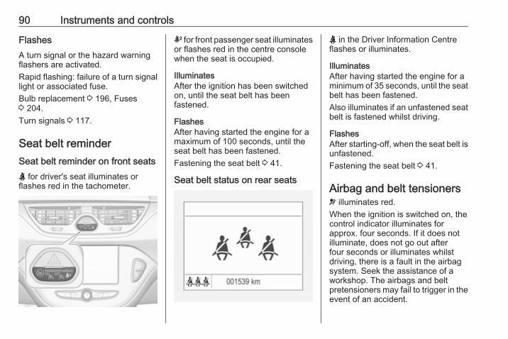
90 Instruments and controls
FlashesA turn signal or the hazard warningflashers are activated.Rapid flashing: failure of a turn signallight or associated fuse.Bulb replacement 3 196, Fuses3 204.Turn signals 3 117.
Seat belt reminderSeat belt reminder on front seatsX for driver's seat illuminates orflashes red in the tachometer.
k for front passenger seat illuminatesor flashes red in the centre consolewhen the seat is occupied.
IlluminatesAfter the ignition has been switchedon, until the seat belt has beenfastened.
FlashesAfter having started the engine for amaximum of 100 seconds, until theseat belt has been fastened.Fastening the seat belt 3 41.
Seat belt status on rear seats
X in the Driver Information Centreflashes or illuminates.
IlluminatesAfter having started the engine for aminimum of 35 seconds, until the seatbelt has been fastened.Also illuminates if an unfastened seatbelt is fastened whilst driving.
FlashesAfter starting-off, when the seat belt isunfastened.Fastening the seat belt 3 41.
Airbag and belt tensionersv illuminates red.When the ignition is switched on, thecontrol indicator illuminates forapprox. four seconds. If it does notilluminate, does not go out afterfour seconds or illuminates whilstdriving, there is a fault in the airbagsystem. Seek the assistance of aworkshop. The airbags and beltpretensioners may fail to trigger in theevent of an accident.

Instruments and controls 91
Deployment of the belt pretensionersor airbags is indicated by continuousillumination of v.
9 Warning
Have the cause of the faultremedied immediately by aworkshop.
Belt pretensioners, airbag system3 40, 3 43.
Airbag deactivationV illuminates yellow.Illuminates for approx. 60 secondsafter the ignition is switched on. Thefront passenger airbag is activated.* illuminates yellow.The front passenger airbag isdeactivated 3 48.
9 Danger
Risk of fatal injury for a child usinga child restraint system togetherwith activated front passengerairbag.Risk of fatal injury for an adultperson with deactivated frontpassenger airbag.
Charging systemp illuminates red.Illuminates when the ignition isswitched on and extinguishes shortlyafter the engine starts.
Illuminates when the engine isrunningStop, switch off engine. Vehiclebattery is not charging. Enginecooling may be interrupted. Thebrake servo unit may cease to beeffective. Seek the assistance of aworkshop.
Malfunction indicator lightZ illuminates or flashes yellow.
Illuminates when the ignition isswitched on and extinguishes shortlyafter the engine starts.
Illuminates when the engine isrunningFault in the emission control system.The permitted emission limits may beexceeded. Seek the assistance of aworkshop immediately.
Flashes when the engine isrunningFault that could lead to catalyticconverter damage. Ease up on theaccelerator until the flashing stops.Seek the assistance of a workshopimmediately.
Service vehicle soong illuminates yellow.Additionally, a warning message isdisplayed in the Driver InformationCentre.The vehicle requires a service.Seek the assistance of a workshop.Vehicle messages 3 102.

92 Instruments and controls
Brake and clutch systemR illuminates red.The brake and clutch fluid level is toolow, when manual parking brake isnot applied 3 193.
9 Warning
Stop. Do not continue yourjourney. Consult a workshop.
Illuminates when the manual parkingbrake is applied and ignition isswitched on 3 149.
Operate pedal- illuminates or flashes yellow.
IlluminatesClutch pedal must be depressed tostart the engine in Autostop mode.Stop-start system 3 135.
FlashesClutch pedal must to be depressed fora main start of the engine 3 17,3 134.
On some versions, the operate pedalmessage is indicated in the DriverInformation Display 3 102.
Antilock brake system(ABS)u illuminates yellow.Illuminates for a few seconds after theignition is switched on. The system isready for operation when the controlindicator extinguishes.If the control indicator does not go outafter a few seconds, or if it illuminateswhile driving, there is a fault in theABS. The brake system remainsoperational but without ABSregulation.Antilock brake system 3 148.
Gear shiftingR with the number of the next highergear is indicated, when upshifting isrecommended for fuel savingreasons.
Power steeringc illuminates yellow.
Illuminates with power steeringdisabledFailure in the power steering system.Consult a workshop.
Illumination of c and bsimultaneouslyPower steering system must becalibrated, system calibration 3 152.
Lane departure warning) illuminates green or flashes yellow.
Illuminates greenSystem is switched on and ready tooperate.
Flashes yellowSystem recognises an unintendedlane change.Lane departure warning 3 175.

Instruments and controls 93
Ultrasonic parking assistr illuminates yellow.Fault in systemorFault due to sensors that are dirty orcovered by ice or snoworInterference due to external sourcesof ultrasound. Once the source ofinterference is removed, the systemwill operate normally.Have the cause of the fault in thesystem remedied by a workshop.Ultrasonic parking assist 3 159.
Electronic Stability Controlofft illuminates yellow.The system is deactivated.
Electronic Stability Controland Traction Control systemb flashes or illuminates yellow.
FlashesThe system is actively engaged.Engine output may be reduced andthe vehicle may be brakedautomatically to a small degree.
IlluminatesA fault in the system is present. Awarning message or warning codeappears in the Driver InformationCentre. Continued driving is possible.The system is not operational. Drivingstability, however, may deterioratedepending on road surfaceconditions.Have the cause of the fault remediedby a workshop.Electronic Stability Control 3 151,Traction Control system 3 150.
Traction Control system offk illuminates yellow.The system is deactivated.
Preheating! illuminates yellow.
Preheating of diesel engine isactivated. Only activates whenoutside temperature is low.
Diesel particle filter% illuminates or flashes yellow.The diesel particle filter requirescleaning.Continue driving until %extinguishes. If possible, do not allowengine speed to drop below2000 rpm.
IlluminatesThe diesel particle filter is full. Startcleaning process as soon aspossible.
FlashesThe maximum filling level of the filteris reached. Start cleaning processimmediately to avoid damage to theengine.Diesel particle filter 3 139, Stop-startsystem 3 135.

94 Instruments and controls
Tyre pressure monitoringsystemw illuminates or flashes yellow.
IlluminatesTyre pressure loss. Stop immediatelyand check tyre pressure.
FlashesFault in system or tyre withoutpressure sensor mounted (e.g. sparewheel). After 60-90 seconds thecontrol indicator illuminatescontinuously. Consult a workshop.Tyre pressure monitoring system3 212.
Engine oil pressureI illuminates red.Illuminates when the ignition isswitched on and extinguishes shortlyafter the engine starts.
Illuminates when the engine isrunning
Caution
Engine lubrication may beinterrupted. This may result indamage to the engine and/orlocking of the drive wheels.
1. Depress the clutch.2. Set selector lever to neutral.3. Move out of the flow of traffic as
quickly as possible withoutimpeding other vehicles.
4. Switch off the ignition.
9 Warning
When the engine is off,considerably more force is neededto brake and steer.During an Autostop, the brakeservo unit will still be operational.Do not remove key until vehicle isstationary, otherwise the steeringwheel lock could engageunexpectedly.
Check oil level before seeking theassistance of a workshop 3 190.
Low fuelY illuminates or flashes yellow.
IlluminatesLevel in fuel tank is too low.
FlashesFuel used up. Refuel immediately.Never run the fuel tank dry.Refuelling 3 178.Catalytic converter 3 140.Bleeding the diesel fuel system3 195.
Immobiliserd flashes yellow.Fault in the immobiliser system. Theengine cannot be started.
Reduced engine power# illuminates yellow.

Instruments and controls 95
The engine power is limited. Consulta workshop.
AutostopAutostop activeD illuminates red or white.Engine is in an Autostop.Stop-start system 3 135.
Exterior light8 illuminates green.The exterior lights are on 3 112.
High beamC illuminates blue.Illuminated when high beam is on orduring headlight flash 3 114.
High beam assistl illuminates green.The high beam assist is activated3 115.
Fog light> illuminates green.The front fog lights are on 3 117.
Rear fog lightr illuminates yellow.The rear fog light is on 3 117.
Cruise controlm illuminates white or green.
Illuminates whiteThe system is on.
Illuminates greenCruise control is active.Cruise control 3 153.
Vehicle detected aheadA illuminates green.A vehicle ahead is detected in thesame lane.Forward collision alert 3 156.
Speed limiterL illuminates in the DriverInformation Centre when Speedlimiter is active. Set speed is indicatedalongside L symbol.Speed limiter 3 155.
Traffic sign assistantL displays detected traffic signs as acontrol indicator.Traffic sign assistant 3 171.
Door openh illuminates.A door or the tailgate is open.

96 Instruments and controls
Information displaysDriver Information CentreThe Driver Information Centre islocated in the instrument cluster.Depending on the version andequipment, the Driver InformationCentre is available as Midleveldisplay or Uplevel display.The following menus are selectable inthe Driver Information Centre usingthe buttons on the turn signal lever:● vehicle information and settings● trip/fuel information● economic information
The following indications appearwhen appropriate:● warning messages 3 102● gear shift indication 3 92● drive mode indication 3 140,
3 145● tyre pressure warning 3 212● seat belt reminder indication
3 90
● Autostop indication 3 135● service information 3 91
Midlevel display
Main menus are:● trip/fuel information, see
description below● vehicle information, see
description belowSome of the displayed functions differwhen the vehicle is being driven or ata standstill. Some functions are onlyavailable when the vehicle is beingdriven.
Uplevel display
Main menus are:● trip/fuel information, displayed
by ;, see description below● vehicle information, displayed
by ?, see description below● eco information, displayed by
@, see description belowSome of the displayed functions differwhen the vehicle is being driven or ata standstill. Some functions are onlyavailable when the vehicle is beingdriven.

Instruments and controls 97
Selecting menus and functionsThe menus and functions can beselected via the buttons on the turnsignal lever.
Press MENU to switch between themain menus or to return from asubmenu to the next higher menulevel.Turn the adjuster wheel to select asubmenu of the main menu or to seta numeric value.Press SET/CLR to select and confirma function.
Vehicle and service messages arepopped-up in the Driver InformationCentre if required. Confirm messagesby pressing SET/CLR. Vehiclemessages 3 102.
Trip/Fuel informationPossible pages are:● digital vehicle speed● trip odometer● average fuel economy● average vehicle speed● instantaneous fuel economy● fuel range● fuel range LPG version● timer● outside temperature
Selection and indication is differentbetween Midlevel display and Upleveldisplay.
Digital vehicle speedDigital display of the instantaneousspeed.
Trip odometerTrip odometer displays the currentdistance since a certain reset.Trip odometer counts up to9999 miles and then restarts at 0.Turn the adjuster wheel to selectbetween trip odometer 1 and 2 forUplevel display.To reset, press SET/CLR for a fewseconds while viewing this page.The information of trip page 1 and 2can be reset separately while therespective display is active.
Average fuel economyDisplay of average consumption. Themeasurement can be reset at anytime and starts with a default value.To reset, press SET/CLR for a fewseconds while viewing this page.The information of trip page 1 and 2can be reset separately while therespective display is active.On vehicles with LPG engines:Average consumption is indicated forthe currently selected mode, LPG orpetrol.

98 Instruments and controls
Average vehicle speedDisplay of average speed. Themeasurement can be reset at anytime.To reset, press SET/CLR for a fewseconds while viewing this page.The information of trip page 1 and 2can be reset separately while therespective display is active.
Instantaneous fuel economyDisplay of the instantaneousconsumption.On vehicles with LPG engines:Instantaneous consumption isindicated for the currently selectedmode, LPG or petrol.
Fuel rangeRange is calculated from current fueltank level and current consumption.The display shows average values.After refuelling, the range is updatedautomatically after a brief delay.When the fuel level in the tank is low,a message appears on the displayand control indicator Y in the fuelgauge illuminates.
When the tank must be refuelledimmediately, a warning messageappears and remains on the display.Additionally, control indicator Yflashes in the fuel gauge 3 94.
Fuel range, LPG version
Display of the approximate total fuelrange for each fuel tank (LPG andpetrol). A low fuel level in either tankis indicated by Low in the respectivesection.
TimerTo operate follow the instructions onthe display.
Outside temperatureDisplay of current outsidetemperature.
Vehicle informationPossible pages are:● unit● speed warning● remaining engine oil life
indication● tyre pressure● tyre loading● outside temperature● following distance● traffic sign assistant● language
Selection and indication is differentbetween Midlevel display and Upleveldisplay.
UnitPress SET/CLR while page isdisplayed. Select imperial (unit 1) ormetric (unit 3) by turning the adjusterwheel. Press SET/CLR to set the unitof measurement.

Instruments and controls 99
Speed warning
The speed warning function alerts thedriver when a set speed is exceeded.To set the speed warning, pressSET/CLR while the page is displayed.Turn the adjuster wheel to select thevalue. Press SET/CLR to set thespeed.If the selected speed limit isexceeded, a warning chime sounds.Once the speed is set, this featurecan be turned off by pressingSET/CLR while viewing this page.
Remaining oil lifeIndicates an estimate of the oil'suseful life. The number in percentagemeans the current remaining oil lifeand indicates when to change theengine oil and filter 3 86.
Tyre pressureTyre pressures of all wheels aredisplayed on this page during driving3 212.
Tyre loadThe tyre pressure category accordingto the actual tyre inflation pressurecan be selected 3 212.
Outside temperatureDisplay of current outsidetemperature.
Following distanceDisplays the distance in seconds to apreceding moving vehicle 3 158.
Traffic sign assistantDisplays the detected traffic signs forthe current route section 3 171.
LanguageSelect preferred country language asthe display language.
ECO informationPossible pages are:● economy trend● economy index● top consumers
Economy trend
Displays the average consumptiondevelopment over a distance of31 miles. Filled segments display theconsumption in 3.1 mile steps and

100 Instruments and controls
shows the effect of topography ordriving behaviour on fuelconsumption.Graph can be reset by pressingSET/CLR.
Economy indexThe current fuel consumption isindicated on an economic scale. Foreconomical driving, adapt drivingstyle to keep the filled segmentswithin the Eco area. The moresegments are filled, the higher thefuel consumption.Simultaneously, the averageconsumption value is indicated.
Top consumersList of top comfort consumerscurrently switched on is displayed indescending order. Fuel savingpotential is indicated.During sporadic driving conditions,the engine will activate the heatedrear window automatically to increasethe engine load. In this event, theheated rear window is indicated asone of the top consumers, withoutactivation by the driver.
Colour-Info-DisplayDepending on the vehicleconfiguration, the vehicle has aColour-Info-Display with touch screenfunctionality.The Colour-Info-Display with touchscreen functionality indicates incolour:● time 3 80● outside temperature 3 79● date 3 80● rear view camera indication
3 170● parking assist and advanced
parking assist instructions3 159
● electronic climate control settings3 125
● Infotainment system, seedescription in the Infotainmentmanual
● system messages● vehicle messages 3 102● settings for vehicle
personalisation 3 105
The type of information and how it isdisplayed depends on the settingsmade.
Selecting menus and settingsMenus and settings are selected viathe touch screen display.
Press X to switch on the display.Press ; to display the homepage.Tap required menu display icon withthe finger.Tap a respective icon to confirm aselection.Tap 9 to return to the next highermenu level.

Instruments and controls 101
Press ; to return to the homepage.For further information, seeInfotainment manual.Vehicle personalisation 3 105.
Graphic-Info-DisplayDepending on the vehicleconfiguration, the vehicle has aGraphic-Info-Display.
The Graphic-Info-Display indicates:● time 3 80● outside temperature 3 79● date 3 80
● electronic climate control settings3 125
● Infotainment system, seedescription in the Infotainmentmanual
● settings for vehiclepersonalisation 3 105
Selecting menus and settingsMenus and settings are accessed viathe display.
Press CONFIG: Menu page Settingsis displayed.Turn knob MENU-TUNE to select asetting or value.Press knob MENU-TUNE to confirma setting or value.
Press BACK to exit a menu or settingwithout changing or delete the lastcharacter in a character sequence.Press the button for a few seconds todelete the entire entry.To exit the Settings menu, pressBACK in steps or press CONFIG afterconfirming the changes.Vehicle personalisation 3 105.Memorised settings 3 22.

102 Instruments and controls
Vehicle messagesMessages are indicated mainly in theDriver Information Centre, in somecases together with a warning andsignal buzzer.
Press SET/CLR, MENU or turn theadjuster wheel to confirm a message.
Vehicle messages on Midleveldisplay
The vehicle messages are displayedas code numbers.
No. Vehicle message
1 Change engine oil
3 Engine coolant level low
4 Air conditioning off
5 Steering wheel is locked
7 Turn steering wheel, switchignition off and then on
No. Vehicle message
9 Turn steering wheel, startengine again
12 Vehicle overloaded
13 Compressor overheated
15 Centre high-mounted brakelight failure
16 Brake light failure
17 Headlight levelling malfunction
18 Left low beam failure
19 Rear fog light failure
20 Right low beam failure
21 Left sidelight failure
22 Right sidelight failure
23 Reversing light failure
24 Number plate light failure
25 Left front turn signal failure
26 Left rear turn signal failure
27 Right front turn signal failure

Instruments and controls 103
No. Vehicle message
28 Right rear turn signal failure
29 Check trailer brake light
30 Check trailer reversing light
31 Check left trailer turn signal
32 Check right trailer turn signal
33 Check trailer rear fog light
34 Check trailer rear light
35 Replace battery in radio remotecontrol
48 Clean side blind spot alertsystem
49 Lane departure warningunavailable
53 Tighten fuel filler cap
54 Water in diesel fuel filter
55 Diesel particle filter is full3 139
56 Tyre pressure imbalance onfront axle
No. Vehicle message
57 Tyre pressure imbalance onrear axle
58 Tyres without TPMS sensorsdetected
59 Open then close driver window
60 Open then close frontpassenger window
65 Theft attempted
66 Service anti-theft alarm system
67 Service steering wheel lock
68 Service power steering
75 Service air conditioning
76 Service side blind spot alertsystem
79 Top up engine oil
81 Service transmission
82 Change engine oil soon
84 Engine power reduced
89 Service vehicle soon
No. Vehicle message
94 Shift to park before exiting
95 Service airbag
128 Bonnet open
134 Parking assist fault, cleanbumper
136 Service parking assist
145 Check washer fluid level
174 Low vehicle battery
151 Press clutch to start
258 Parking assist off
Vehicle messages on Uplevel-DisplayThe vehicle messages are displayedas text. Follow the instructions givenin the messages.The system displays messagesregarding the following topics:● service messages● fluid levels● anti-theft alarm system
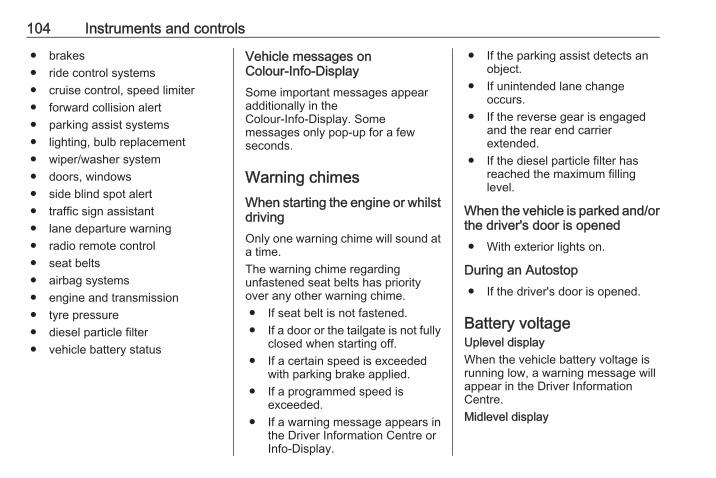
104 Instruments and controls
● brakes● ride control systems● cruise control, speed limiter● forward collision alert● parking assist systems● lighting, bulb replacement● wiper/washer system● doors, windows● side blind spot alert● traffic sign assistant● lane departure warning● radio remote control● seat belts● airbag systems● engine and transmission● tyre pressure● diesel particle filter● vehicle battery status
Vehicle messages onColour-Info-DisplaySome important messages appearadditionally in theColour-Info-Display. Somemessages only pop-up for a fewseconds.
Warning chimesWhen starting the engine or whilstdrivingOnly one warning chime will sound ata time.The warning chime regardingunfastened seat belts has priorityover any other warning chime.● If seat belt is not fastened.● If a door or the tailgate is not fully
closed when starting off.● If a certain speed is exceeded
with parking brake applied.● If a programmed speed is
exceeded.● If a warning message appears in
the Driver Information Centre orInfo-Display.
● If the parking assist detects anobject.
● If unintended lane changeoccurs.
● If the reverse gear is engagedand the rear end carrierextended.
● If the diesel particle filter hasreached the maximum fillinglevel.
When the vehicle is parked and/orthe driver's door is opened● With exterior lights on.
During an Autostop● If the driver's door is opened.
Battery voltageUplevel displayWhen the vehicle battery voltage isrunning low, a warning message willappear in the Driver InformationCentre.Midlevel display

Instruments and controls 105
When the vehicle battery voltage isrunning low, a warning code 174 willappear in the Driver InformationCentre.1. Switch off immediately any
electrical consumers which arenot required for a safe drive, e.g.seat heating, heated windscreenand heated rear window or othermain consumers.
2. Charge the vehicle battery bydriving continuously for a while orby using a charging device.
The warning message or warningcode will disappear after the enginehas been started twice consecutivelywithout a voltage drop.If the vehicle battery cannot berecharged, have the cause of the faultremedied by a workshop.
Vehicle personalisationThe vehicle's behaviour can bepersonalised by changing the settingsin the Info-Display.Some of the personal settings fordifferent drivers can be memorisedindividually for each vehicle key.Memorised settings 3 22.Depending on vehicle equipment andcountry-specific regulations, some ofthe functions described below mightnot be available.Some functions are only displayed oractive when the engine is running.
Personal settingsGraphic-Info-DisplayPress CONFIG for the Settings menu.Turn the MENU-TUNE control tomove to the desired setup menu, andthen press MENU-TUNE.
Select Settingsand then Vehiclesettings.
Vehicle settings● Climate and air quality
Auto fan speed: Modifies thelevel of the cabin airflow of theclimate control in Automaticmode.

106 Instruments and controls
Auto rear demist: Activatesautomatically the heated rearwindow.
● Comfort settingsChime volume: Changes thevolume of warning chimes.Personalization by driver:Activates or deactivates thepersonalisation function.Rear auto wipe in reverse:Activates or deactivatesautomatic switching on of therear window wiper when reversegear is engaged.
● Park assist / Collision detectionPark assist: Activates ordeactivates the ultrasonicparking assist. Activation isselectable with or withoutattached trailer coupling.Side blind zone alert: Changesthe settings for the side blind spotalert system.
● Exterior ambient lightingExterior lighting by unlocking:Activates or deactivates the entrylighting.
Duration upon exit of vehicle:Activates or deactivates andchanges the duration of exitlighting.
● Power door locksAuto door lock: Activates ordeactivates the automatic doorlocking function after switchingon ignition.Stop door lock if door open:Activates or deactivates the doorlocking function while a door isopen.Delayed door lock: Activates ordeactivates the delayed doorlocking function. This menuoption is displayed with Stop doorlock if door open deactivated.Central locking system 3 22.
● Remote locking, unlocking,startingRemote unlock feedback:Activates or deactivates thehazard warning flasher feedbackwhilst unlocking.Passive door unlock: Changesthe configuration to unlock only
the driver's door or the wholevehicle whilst unlocking.Auto relock doors: Activates ordeactivates the automatic relockfunction after unlocking withoutopening the vehicle.
● Restore factory settings:Resets all settings to the defaultsettings.
Personal settingsColour-Info-DisplayWhen audio is switched on, press ;on the control panel.

Instruments and controls 107
Select Settingsand then Vehiclesettings.
Vehicle settings● Climate & air quality
Auto Fan Max Speed: Modifiesthe level of the cabin airflow of theclimate control in automaticmode.Air Conditioning Mode: Controlsthe state of the coolingcompressor when the vehicle isstarted. Last setting(recommended) or at vehiclestart is either always on or alwaysoff.
Auto Rear Defog: Automaticallyactivates heated rear window.
● Collision / Detection SystemsPark Assist: Activates ordeactivates the ultrasonicparking assist. Activation isselectable with or withoutattached trailer coupling.Side Blind Zone Alert: Activatesor deactivates side blind zonealert.
● Comfort and ConvenienceChime Volume: Changes thevolume of warning chimes.Personalization By Driver:Activates or deactivates thepersonalisation function.Auto Wipe in Reverse Gear:Activates or deactivatesautomatic switching on of therear window wiper when reversegear is engaged.
● LightingVehicle Locator Lights: Activatesor deactivates the entry lighting.
Exit Lighting: Activates ordeactivates and changes theduration of exit lighting.
● Power Door LocksUnlocked Door Anti Lock Out:Activates or deactivates the doorlocking function while a door isopen.Auto Door Lock: Activates ordeactivates the automatic doorlocking function after switchingon ignition.Auto Door Unlock: Changes theconfiguration to unlock only thedriver's door or the whole vehicleafter switching off ignition.Delayed Door Lock: Activates ordeactivates the delayed doorlocking function. This featuredelays the actual locking of thedoors until all doors are closed.
● Remote Lock, Unlock, StartRemote Unlock Light Feedback:Activates or deactivates thehazard warning flasher feedbackwhilst unlocking.Remote Door Unlock: Changesthe configuration to unlock only

108 Instruments and controls
the driver's door or the wholevehicle whilst unlocking.Relock Remotely UnlockedDoors: Activates or deactivatesthe automatic relock functionafter unlocking without openingthe vehicle.
OnStarOnStar is a personal connectivity andservice assistant with integratedWi-Fi hotspot. The OnStar service isavailable 24 hours a day, seven daysa week.NoticeOnStar is not available for allmarkets. For further information,contact your workshop.NoticeIn order to be available andoperational, OnStar needs a validOnStar subscription, functioningvehicle electrics, mobile service andGPS satellite link.
To activate the OnStar services andset up an account, press Z and speakwith an advisor.Depending on the equipment of thevehicle, the following services areavailable:● Emergency services and support
in the case of a vehiclebreakdown
● Wi-Fi hotspot
● Smartphone application● Remote control, e.g. location of
the vehicle, activation of horn andlights, control of central lockingsystem
● Stolen vehicle assistance● Vehicle diagnostics● Destination downloadNoticeThe OnStar module of the vehicle isdeactivated after ten days without anignition cycle. Functions requiring adata connection will be availableagain after switching on the ignition.
OnStar buttons

Instruments and controls 109
Privacy buttonPress and hold j until a message isheard to activate or deactivate thetransmission of the vehicle location.Press j to answer a call or to end acall to an advisor.Press j to access the Wi-Fi settings.
Service buttonPress Z to establish a connection toan advisor.
SOS buttonPress [ to establish a priorityemergency connection to a speciallytrained emergency advisor.
Status LEDGreen: The system is ready.Green flashing: The system is on acall.Red: A problem arose.Off: System is in standby mode.Red / green flashing for a short periodof time: Transmission of the vehiclelocation has been deactivated.
OnStar services
General servicesIf you need any informationconcerning e.g. opening hours, pointsof interest and destinations or if youneed any support e.g. in the case of avehicle breakdown, a flat tyre andempty fuel tank, press Z to establisha connection to an advisor.
Emergency servicesIn the case of an emergency situation,press [ and talk to an advisor. Theadvisor then contacts emergency orassistance service providers anddirects them to your vehicle.In the case of an accident withactivation of airbags or belttensioners, an automatic emergencycall is established. The advisor isimmediately connected to yourvehicle to see whether help isneeded.
Wi-Fi hotspotThe Wi-Fi hotspot of the vehicleprovides internet connectivity with amaximum speed of 4G/LTE.
NoticeThe Wi-Fi hotspot functionality is notavailable for all markets.
Up to seven devices may beconnected.To connect a mobile device with theWi-Fi hotspot:1. Press j and then select Wi-Fi
settings on the Info-Display. Thesettings displayed include the Wi-Fi hotspot name (SSID),password and connection type.
2. Start a Wi-Fi network search onyour mobile device.
3. Select your vehicle hotspot(SSID) when listed.
4. When prompted, enter thepassword on your mobile device.
NoticeTo change the SSID or password,press Z and talk to an advisor or login to your account.
To switch off the Wi-Fi hotspotfunctionality, press Z to call anadvisor.
110 Instruments and controls
Smartphone appWith the My Vauxhall smartphoneapp, some vehicle functions can beoperated remotely.The following functions are available:● Lock or unlock vehicle.● Honk horn or flash lights.● Check fuel level, engine oil life
and tyre pressure (only with tyrepressure monitoring system).
● Send navigation destination tothe vehicle, if equipped with abuilt-in navigation system.
● Locate vehicle on a map.● Manage Wi-Fi settings.
To operate these functions, downloadthe app from Apple's App Store orGoogle Play Store.
Remote controlIf desired, use any phone to call anadvisor, who can remotely operatespecific vehicle functions. Find therespective OnStar phone number onour country-specific website.
The following functions are available:● Lock or unlock vehicle.● Provide information on the
vehicle location.● Honk horn or flash lights.
Stolen vehicle assistanceIf the vehicle is stolen, report the theftto the authorities and request OnStarstolen vehicle assistance. Use anyphone to call an advisor. Find therespective OnStar phone number onour country-specific website.OnStar can provide support inlocating and recovering the vehicle.Theft alertWhen the anti-theft alarm system istriggered, a notification is sent toOnStar. You are then informed aboutthis event by text message or email.Restart preventionBy sending remote signals, OnStarcan prevent the vehicle fromrestarting once it has been turned off.
On-demand diagnosticsAt any time e.g. if the vehicle displaysa vehicle message, press Z tocontact an advisor and ask tocomplete a real-time diagnostic checkto directly determine the issue.Depending on the results, the advisorwill provide further support.
Diagnostic reportThe vehicle automatically transmitsdiagnostic data to OnStar whichsends a monthly email report to youand your preferred workshop.NoticeThe workshop notification functioncan be disabled in your account.
The report contains the status of keyoperating systems of the vehicle likeengine, transmission, airbags, ABS,and other major systems. It alsoprovides information on possiblemaintenance items and tyre pressure(only with tyre pressure monitoringsystem).To look at the information in greaterdetail, select the link within the emailand log in to your account.
Instruments and controls 111
Destination downloadA desired destination can be directlydownloaded to the navigation system.Press Z to call an advisor anddescribe the destination or point ofinterest.The advisor can look up any addressor point of interest and directly sendthe destination to the built-innavigation system.
OnStar settings
OnStar PINTo have full access to all OnStarservices, a four-digit PIN is required.The PIN has to be personalised whenfirst talking to an advisor.To change the PIN, press Z to call anadvisor.
Account dataAn OnStar subscriber has an accountwhere all the data is stored. Torequest a change of the accountinformation, press Z and talk to anadvisor or log in to your account.
If the OnStar service is used onanother vehicle, press Z and requestthat the account be transferred to thenew vehicle.NoticeIn any case, if the vehicle is disposedof, sold or otherwise transferred,immediately inform OnStar aboutthe changes and terminate theOnStar service on this vehicle.
Vehicle locationThe vehicle location is transmitted toOnStar when service is requested ortriggered. A message on the Info-Display informs about thistransmission.To activate or deactivate thetransmission of the vehicle location,press and hold j until an audiomessage is heard.The deactivation is indicated by thestatus light flashing red and green fora short period of time and each timethe vehicle is started.NoticeIf the transmission of the vehiclelocation is deactivated, someservices are no longer available.
NoticeThe vehicle location always remainsaccessible to OnStar in the case ofan emergency.
Find the privacy policy in youraccount.
Software updatesOnStar may remotely carry outsoftware updates without furthernotice or consent. These updates areto enhance or maintain safety andsecurity or the operation of thevehicle.These updates may concern privacyissues. Find the privacy policy in youraccount.

112 Lighting
Lighting
Exterior lighting .......................... 112Light switch .............................. 112Automatic light control ............. 113High beam ............................... 114Headlight flash ......................... 114Headlight range adjustment .... 114Headlights when drivingabroad .................................... 114
Daytime running lights ............. 115Xenon lighting system ............. 115Hazard warning flashers .......... 116Turn and lane-change signals . 117Front fog lights ......................... 117Rear fog light ........................... 117Parking lights ........................... 118Reversing lights ....................... 118Misted light covers ................... 118
Interior lighting ........................... 118Instrument panel illuminationcontrol ..................................... 118
Interior lights ............................ 119Reading lights .......................... 120
Lighting features ........................ 120Entry lighting ............................ 120
Exit lighting .............................. 120Battery discharge protection .... 121 Exterior lighting
Light switch
Turn light switch:7 : lights off8 : sidelights9 : headlights
Control indicator 8 3 95.

Lighting 113
Light switch with automatic lightcontrol
Turn light switch:AUTO : automatic light control:
headlights are switched onand off automaticallydepending on externallighting conditions
m : activation or deactivation ofthe automatic light control.Switch turns back to AUTO
8 : sidelights9 : headlights
A status message in the DriverInformation Centre indicates thecurrent status of the automatic lightcontrol.When switching on the ignition,automatic light control is active.When headlights are on, 8illuminates. Control indicator 83 95.
Tail lightsTail lights are illuminated togetherwith headlights and sidelights.
Automatic light control
When the automatic light controlfunction is switched on and theengine is running, the systemswitches between daytime runninglight and headlights automaticallydepending on the lighting conditionsand information given by the rainsensor system.Daytime running light 3 115.
Automatic headlight activationDuring poor lighting conditions theheadlights are switched on.Furthermore the headlights areswitched on if the windscreen wipershave been activated for severalwipes.
Tunnel detectionWhen a tunnel is entered, theheadlights are switched onimmediately.

114 Lighting
High beam
To switch from low to high beam,push lever.To switch to low beam, push leveragain or pull.High beam assist 3 115.
Headlight flashTo activate the headlight flash, pulllever.
Headlight range adjustmentManual headlight rangeadjustment
To adapt headlight range to thevehicle load to prevent dazzling: turnthumb wheel ? to required position.0 : front seats occupied1 : all seats occupied2 : all seats occupied and load
compartment laden3 : driver's seat occupied and load
compartment laden
Headlights when drivingabroadThe asymmetrical headlight beamextends visibility at the edge of theroad at the passenger side.However, when driving in countrieswhere traffic drives on the oppositeside of the road, adjust the headlightsto prevent dazzling of oncomingtraffic.
There are two adjuster elements oneach headlight housing.Turn both adjuster elements on eachheadlight housing 1/2 turn with asize six hexagon key anticlockwise to
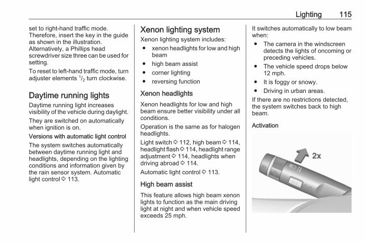
Lighting 115
set to right-hand traffic mode.Therefore, insert the key in the guideas shown in the illustration.Alternatively, a Phillips headscrewdriver size three can be used forsetting.To reset to left-hand traffic mode, turnadjuster elements 1/2 turn clockwise.
Daytime running lightsDaytime running light increasesvisibility of the vehicle during daylight.They are switched on automaticallywhen ignition is on.Versions with automatic light controlThe system switches automaticallybetween daytime running light andheadlights, depending on the lightingconditions and information given bythe rain sensor system. Automaticlight control 3 113.
Xenon lighting systemXenon lighting system includes:● xenon headlights for low and high
beam● high beam assist● corner lighting● reversing function
Xenon headlightsXenon headlights for low and highbeam ensure better visibility under allconditions.Operation is the same as for halogenheadlights.Light switch 3 112, high beam 3 114,headlight flash 3 114, headlight rangeadjustment 3 114, headlights whendriving abroad 3 114.Automatic light control 3 113.
High beam assistThis feature allows high beam xenonlights to function as the main drivinglight at night and when vehicle speedexceeds 25 mph.
It switches automatically to low beamwhen:● The camera in the windscreen
detects the lights of oncoming orpreceding vehicles.
● The vehicle speed drops below12 mph.
● It is foggy or snowy.● Driving in urban areas.
If there are no restrictions detected,the system switches back to highbeam.
Activation

116 Lighting
The high beam assist is activated bypushing the indicator lever twice at aspeed above 25 mph.The green control indicator lilluminates continuously when theassist is activated, the blue one 7illuminates when high beam is on.Control indicator l 3 95.
DeactivationPush indicator lever once. It is alsodeactivated when front fog lights areswitched on.If a headlight flash is activated whenthe high beam is on, the high beamassist will be deactivated.If a headlight flash is activated whenthe high beam is off, the high beamassist will remain activated.The latest setting of the high beamassist will remain after the ignition isswitched on again.
Corner lighting
On tight bends or when turning off,depending on the steering angle orthe indicator light signal, an additionalleft or right reflector is switched onwhich illuminates the road in thedirection of travel. It is activated up toa speed of 25 mph.
Reversing functionIf the low beam is on and reverse gearis engaged, both corner lights areswitched on. They remain illuminatedfor 20 seconds after disengagingreverse gear.
Hazard warning flashers
Operated by pressing ¨.In the event of an accident with airbagdeployment, the hazard warningflashers are activated automatically.

Lighting 117
Turn and lane-changesignals
lever up : right turn signallever down : left turn signal
If the lever is moved past theresistance point, the turn signal isswitched on constantly. When thesteering wheel moves back, the turnsignal is automatically deactivated.For three flashes, e.g. when changinglanes, press the lever until resistanceis felt and then release.
With a trailer connected, turn signalflashes six times and tone frequencychanges when pressing the lever untilresistance is felt and then releasing.Move the lever to the resistance pointand hold for longer indication.Switch the turn signal off manually bymoving the lever to its originalposition.
Front fog lights
Operated by pressing >.Light switch in position AUTO:switching on front fog lights will switchthe low beam on automatically.
Rear fog light
Operated by pressing r.Light switch in position AUTO:switching on rear fog light will switchon headlights automatically.

118 Lighting
Parking lights
When the vehicle is parked, theparking lights on one side can beactivated:1. Switch off the ignition.2. Move the turn signal lever all the
way up (right parking lights) ordown (left parking lights).
Confirmed by an acoustic signal andthe corresponding turn signal controlindicator.
Reversing lightsThe reversing light comes on whenthe ignition is on and reverse gear isselected.
Misted light coversThe inside of the light housing maymist up briefly in poor, wet and coldweather conditions, in heavy rain orafter washing. The mist disappearsquickly by itself; to help switch on theheadlights.
Interior lightingInstrument panelillumination control
Brightness of the following lights canbe adjusted when the exterior lightsare on:● instrument panel illumination● dome light● Info-Display● illuminated switches and
operation elementsTurn thumb wheel A and hold untilthe desired brightness is obtained.
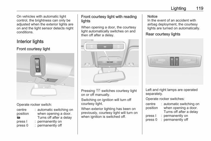
Lighting 119
On vehicles with automatic lightcontrol, the brightness can only beadjusted when the exterior lights areon and the light sensor detects nightconditions.
Interior lightsFront courtesy light
Operate rocker switch:centrepositionw
: automatic switching onwhen opening a door.Turns off after a delay
press I : permanently onpress 0 : permanently off
Front courtesy light with readinglightsWhen opening a door, the courtesylight automatically switches on andthen off after a delay.
Pressing c switches courtesy lighton or off manually.Switching on ignition will turn offcourtesy light.When exterior lighting has been onpreviously, courtesy light will turn onwhen ignition is switched off.
NoticeIn the event of an accident withairbag deployment, the courtesylights are turned on automatically.
Rear courtesy lights
Left and right lamps are operatedseparately.Operate rocker switches:centreposition
: automatic switching onwhen opening a door.Turns off after a delay
press I : permanently onpress 0 : permanently off

120 Lighting
Dome lightSpotlight incorporated in the insidemirror housing comes on whenheadlights are switched on.Dome light illuminates gear shiftingconsole indirectly.
Reading lights
Operated by pressing 2 for the leftand right side.
Lighting featuresEntry lightingWelcome lightingThe following lights are switched onfor a short time by unlocking thevehicle with the radio remote control:● headlights● tail lights● number plate lights● instrument panel light● interior lights
Some functions are only operablewhen it is dark outside, to facilitatelocating the vehicle.Lighting switches off immediatelywhen the ignition key is turned toposition 1 3 133.Activation or deactivation of thisfunction can be changed in theInfo-Display.Vehicle personalisation 3 105.The settings can be saved for the keybeing used 3 22.
The following lights will additionallyswitch on when the driver's door isopened:● illumination of all switches● Driver Information Centre
Exit lightingThe following lights switch on if thekey is removed from the ignitionswitch:● interior lights● instrument panel light (only when
it is dark)They will switch off automatically aftera delay and will be activated again ifthe driver's door is opened.
Path lightingHeadlights, tail lights and numberplate lights illuminate the surroundingarea for an adjustable time afterleaving the vehicle.

Lighting 121
Activating
1. Switch off the ignition.2. Remove the ignition key.3. Open driver's door.4. Pull the turn signal lever.5. Close the driver's door.
If the driver's door is not closed thelights switch off after two minutes.Exit lighting is switched offimmediately if the turn signal lever ispulled while the driver's door is open.Activation, deactivation and durationof this function can be changed in theInfo-Display. Vehicle personalisation3 105.
The settings can be saved for the keybeing used 3 22.
Battery discharge protectionVehicle battery state of chargefunctionThe function guarantees longestvehicle battery life via a generatorwith controllable power output andoptimised power distribution.To prevent discharge of the vehiclebattery when driving, the followingsystems are reduced automatically intwo stages and finally switched off:● heated rear window● heated windscreen● heated mirrors● heated seats● fan
In the second stage, a messagewhich confirms the activation of thevehicle battery discharge protectionwill be displayed in the DriverInformation Centre.
Switching off electric lightsTo prevent discharge of the vehiclebattery when the ignition is switchedoff, some interior lights are switchedoff automatically after some time.
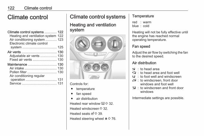
122 Climate control
Climate control
Climate control systems ............. 122Heating and ventilation system 122Air conditioning system ........... 123Electronic climate controlsystem .................................... 125
Air vents ..................................... 130Adjustable air vents ................. 130Fixed air vents ......................... 130
Maintenance .............................. 130Air intake ................................. 130Pollen filter ............................... 130Air conditioning regularoperation ................................ 131
Service .................................... 131
Climate control systemsHeating and ventilationsystem
Controls for:● temperature● fan speed● air distribution
Heated rear window Ü 3 32.Heated windscreen 3 32.Heated seats ß 3 39.Heated steering wheel * 3 76.
Temperaturered : warmblue : cold
Heating will not be fully effective untilthe engine has reached normaloperating temperature.
Fan speedAdjust the air flow by switching the fanto the desired speed.
Air distributionM : to head areaL : to head area and foot wellK : to foot well and windscreenJ : to windscreen, front door
windows and foot welll : to windscreen and front door
windows
Intermediate settings are possible.

Climate control 123
Demisting and defrosting thewindows
● Set temperature control towarmest level.
● Set fan speed to highest speed.● Set air distribution control to l.● Switch on heated rear window Ü.● Open side air vents as required
and direct them towards doorwindows.
● For simultaneous warming of thefoot well, set air distributioncontrol to J.
Air conditioning system
Controls for:● temperature● fan speed● air distributionn : cooling4 : air recirculationÜ : heated rear window 3 32
Heated windscreen 3 32.Heated seats ß 3 39.Heated steering wheel * 3 76.
Temperaturered : warmblue : cold
Heating will not be fully effective untilthe engine has reached normaloperating temperature.
Fan speedAdjust the air flow by switching the fanto the desired speed.
Air distributionM : to head areaL : to head area and foot wellK : to foot well and windscreenJ : to windscreen, front door
windows and foot welll : to windscreen and front door
windows (air conditioning isactivated in the background tohelp preventing windows fromfogging)
Intermediate settings are possible.

124 Climate control
Cooling n
Press n to switch on cooling. TheLED in the button illuminates toindicate activation. Cooling is onlyfunctional when the engine is runningand climate control fan is switched on.Press n again to switch off cooling.The air conditioning system cools anddehumidifies (dries) as soon as theoutside temperature is slightly abovethe freezing point. Thereforecondensation may form and drip fromunder the vehicle.If no cooling or drying is required,switch off the cooling system for fuelsaving reasons.
Activated cooling may inhibitAutostops.Stop-start system 3 135.
Air recirculation system 4
Press 4 to activate air recirculationmode. The LED in the buttonilluminates to indicate activation.Press 4 again to deactivate airrecirculation mode.
9 Warning
The exchange of fresh air isreduced in air recirculation mode.In operation without cooling the air
humidity increases, so thewindows may mist up from inside.The quality of the passengercompartment air deteriorates,which may cause the vehicleoccupants to feel drowsy.
In warm and very humid ambient airconditions, the windscreen may mistup from outside, when cold air isdirected towards it. If windscreenmists up from outside, activatewindscreen wiper and deactivate l.
Maximum coolingBriefly open the windows so that hotair can disperse quickly.

Climate control 125
● Switch on cooling n.● Air recirculation system 4 on.● Set temperature control to
coldest level.● Set fan speed to highest level.● Set air distribution control to M.● Open all vents.
Demisting and defrosting thewindows l
● Set temperature control towarmest level.
● Set fan speed to highest level.● Set air distribution control to l.● Switch on heated rear window Ü.● Open side air vents as required
and direct them towards the doorwindows.
NoticeIf air distribution mode l is selectedwhile engine is running, an Autostopwill be inhibited until another airdistribution is selected.If air distribution mode l is selectedwhile the engine is in an Autostop,the engine will restart automatically.
Stop-start system 3 135.
Electronic climate controlsystem

126 Climate control
Controls for:● fan speed● temperature● air distributionn : coolingAUTO : automatic mode4 : manual air recirculationV : demisting and defrostingÜ : heated rear window 3 32
Heated windscreen 3 32.Heated seats ß 3 39.Heated steering wheel * 3 76.In Automatic mode, temperature, fanspeed and air distribution areregulated automatically.
Climate control settings are shown onthe Info-Display. Settingmodifications are briefly popped-up,superimposed over the currentlydisplayed menu.The electronic climate control systemis only fully operational when theengine is running.
Automatic mode AUTO
Basic setting for maximum comfort:● Press AUTO, air distribution and
fan speed are regulatedautomatically. The LED in thebutton illuminates to indicateactivation.
● Open all air vents to allowoptimised air distribution inAutomatic mode.
● Press n to switch on optimalcooling and demisting. The LEDin the button illuminates toindicate activation.
● Set the preselected temperatureusing the centre rotary knob.Recommended temperature is22 °C.
Temperature preselectionSet temperature by turning the centrerotary knob to the desired value. It isindicated on the display in the switch.For reasons of comfort, changetemperature only in small increments.

Climate control 127
If the minimum temperature Lo is set,the climate control system runs atmaximum cooling if cooling n isswitched on.If the maximum temperature Hi is set,the climate control system runs atmaximum heating.NoticeIf n is switched on, reducing the setcabin temperature can cause theengine to restart from an Autostop orinhibit an Autostop.
Stop-start system 3 135.
Demisting and defrosting thewindows V
● Press V. The LED in the buttonilluminates to indicate activation.
● Temperature and air distributionare set automatically and the fanruns at high speed.
● Switch on heated rear window Ü.● To return to previous mode:
press V. To return to Automaticmode: press AUTO.
Setting of automatic rear windowheating can be changed in theInfo-Display. Vehicle personalisation3 105.
NoticeIf V is pressed while the engine isrunning, an Autostop will be inhibiteduntil V is pressed again.If s is pressed with the fan switchedon and the engine running, anAutostop will be inhibited until s ispressed again or until the fan isswitched off.If V is pressed while the engine isin an Autostop, the engine will restartautomatically.If s is pressed with the fan switchedon while the engine is in anAutostop, the engine will restartautomatically.
Stop-start system 3 135.
Manual settingsClimate control system settings canbe changed by activating the buttonsand rotary knobs as follows.Changing a setting will deactivateAutomatic mode.

128 Climate control
Fan speed Z
Turn left rotary knob to decrease orincrease fan speed. The fan speed isindicated in the Info-Display.Turning knob to $: fan and coolingare switched off.To return to Automatic mode: PressAUTO.
Air distribution
Turn right rotary knob for desiredadjustment. Setting is indicated in theInfo-Display.K : to foot well and windscreen9 : to windscreen, front door
windows and foot wells : to windscreen and front door
windows (air conditioning isactivated in the background tohelp preventing windows fromfogging)
M : to head area via adjustable airvents
L : to head area and foot well
Return to Automatic air distribution:press AUTO.
Cooling n
Press n to switch on cooling. TheLED in the button illuminates toindicate activation. Cooling is onlyfunctional when the engine is runningand climate control fan is switched on.Press n again to switch off cooling.The air conditioning system cools anddehumidifies (dries) as soon as theoutside temperature is slightly abovethe freezing point. Thereforecondensation may form and drip fromunder the vehicle.

Climate control 129
If no cooling or drying is required,switch off the cooling system for fuelsaving reasons.When the cooling system is switchedoff, no engine restart will berequested by the climate controlsystem during an Autostop.Exception: defrost system is activatedand outside temperature above 0 °Crequests a restart.Stop-start system 3 135.The status of cooling operation isindicated in the Info-Display.Activation or deactivation of coolingoperation after engine start can bechanged in the Info-Display. Vehiclepersonalisation 3 105.
Air recirculation mode 4
Press 4 to activate air recirculationmode. The LED in the buttonilluminates to indicate activation.Press 4 again to deactivate airrecirculation mode.
9 Warning
The exchange of fresh air isreduced in air recirculation mode.In operation without cooling, theair humidity increases, so thewindows may mist up from inside.The quality of the passenger
compartment air deteriorates,which may cause the vehicleoccupants to feel drowsy.
In warm and very humid ambient airconditions, the windscreen may mistup from outside when cold air isdirected towards it. If windscreenmists up from outside, activatewindscreen wiper and deactivate s.
Basic settingsSome settings can be changed in theInfo-Display. Vehicle personalisation3 105.

130 Climate control
Air ventsAdjustable air ventsAt least one air vent must be openwhile the cooling is on.
Adjust the air amount at the ventoutlet by turning the adjuster wheel.The vent is closed when the adjusterwheel is turned close to the left orright.
Direct the flow of air by tilting andswivelling the slats.
9 Warning
Do not attach any objects to theslats of the air vents. Risk ofdamage and injury in case of anaccident.
Fixed air ventsAdditional air vents are locatedbeneath the windscreen and doorwindows and in the foot wells.
MaintenanceAir intake
The air intake in front of thewindscreen in the enginecompartment must be kept clear toallow air intake. Remove any leaves,dirt or snow.
Pollen filterThe pollen filter cleans dust, soot,pollen and spores from the airentering the vehicle through the airintake.

Climate control 131
Air conditioning regularoperationIn order to ensure continuouslyefficient performance, cooling mustbe operated for a few minutes once amonth, irrespective of the weatherand time of year. Operation withcooling is not possible when theoutside temperature is too low.
ServiceFor optimal cooling performance, it isrecommended to annually check theclimate control system, startingthree years after initial vehicleregistration, including:● functionality and pressure test● heating functionality● leakage check● check of drive belts● cleaning of condenser and
evaporator drainage● performance check

132 Driving and operating
Driving andoperating
Driving hints ............................... 133Control of the vehicle ............... 133
Starting and operating ............... 133New vehicle running-in ............ 133Ignition switch positions ........... 133Retained power off .................. 134Starting the engine .................. 134Overrun cut-off ........................ 135Stop-start system .................... 135Parking .................................... 138
Engine exhaust .......................... 139Diesel particle filter .................. 139Catalytic converter ................... 140
Automatic transmission .............. 140Transmission display ............... 140Selector lever .......................... 141Manual mode ........................... 142Electronic driving programmes 142Fault ........................................ 143Interruption of power supply .... 143
Manual transmission .................. 144
Manual transmission automa‐ted .............................................. 144
Transmission display ............... 145Starting the engine .................. 145Selector lever .......................... 145Manual mode ........................... 147Electronic driving programmes 147Fault ........................................ 147
Brakes ........................................ 148Antilock brake system ............. 148Parking brake .......................... 149Brake assist ............................. 149Hill start assist ......................... 149
Ride control systems ................. 150Traction Control system .......... 150Electronic Stability Control ...... 151City mode ................................ 152
Driver assistance systems ......... 153Cruise control .......................... 153Speed limiter ........................... 155Forward collision alert ............. 156Following distance indication ... 158Parking assist .......................... 159Side blind spot alert ................. 169Rear view camera ................... 170Traffic sign assistant ................ 171Lane departure warning .......... 175
Fuel ............................................ 176Fuel for petrol engines ............. 176
Fuel for diesel engines ............ 176Fuel for liquid gas operation .... 176Refuelling ................................ 178Fuel consumption - CO2-Emissions .............................. 181
Trailer hitch ................................ 182General information ................. 182Driving characteristics andtowing tips .............................. 182
Trailer towing ........................... 183Towing equipment ................... 184Trailer stability assist ............... 186

Driving and operating 133
Driving hintsControl of the vehicleNever coast with engine notrunningMany systems will not function in thissituation (e.g. brake servo unit, powersteering). Driving in this manner is adanger to yourself and others.All systems function during anAutostop.Stop-start system 3 135.
Idle boostIf charging of the vehicle battery isrequired due to battery condition, thepower output of the generator mustbe increased. This will be achieved byan idle boost which may be audible.A message appears in the DriverInformation Centre.
PedalsTo ensure the pedal travel isuninhibited, there must be no mats inthe area of the pedals.
Use only floor mats, which fit properlyand are fixed by the retainers on thedriver side.
Driving downhillEngage a gear when driving downhillto ensure that sufficient brakepressure is available.
Starting and operatingNew vehicle running-inDo not brake unnecessarily hard forthe first few journeys.During the first drive, smoke mayoccur because of wax and oilevaporating off the exhaust system.Park the vehicle in the open for awhile after the first drive and avoidinhaling the fumes.During the running-in period, fuel andengine oil consumption may behigher.Additionally, the cleaning process ofthe diesel particle filter may takeplace more often.Diesel particle filter 3 139.Autostop may be inhibited to allow forcharging of the vehicle battery.
Ignition switch positionsTurn key:

134 Driving and operating
0 : ignition off: Some functionsremain active until key isremoved or driver's door isopened, provided the ignition wason previously
1 : accessory power mode: Steeringwheel lock released, someelectrical functions are operable,ignition is off
2 : ignition on power mode: Ignitionis on. Control indicatorsilluminate and most electricalfunctions are operableDiesel engine is preheating.
3 : engine start: Release key afterstarting procedure begins
Steering wheel lockRemove key from ignition switch andturn steering wheel until it engages.
Retained power offThe following electronic systems areoperable until the driver's door isopened or at the latest for ten minutesafter the ignition is switched off:● power windows● power outlets● power sunroof
Power to the Infotainment system willcontinue to operate for 30 minutes oruntil the key is removed from theignition switch, regardless of whetherany door is opened.
Starting the engine
Turn key to position 1 to release thesteering wheel lock.Manual transmission: operate clutchand brake pedal.Manual transmission automated:operate brake pedal.Automatic transmission: operatebrake pedal and move selector leverto P or N.Do not operate the accelerator pedal.Diesel engine: turn the key to position2 for preheating until controlindicator ! extinguishes.

Driving and operating 135
Turn key briefly to position 3 andrelease: an automatic procedureoperates the starter after a briefdelay, until the engine is running. See'Automatic Starter Control'.Before restarting or to switch off theengine, turn the key back to position0.During an Autostop, the engine canbe started by depressing the clutchpedal.
Starting the vehicle at lowtemperaturesDiesel enginesThe start of the engine withoutadditional heaters is possible down to-25 °С.Petrol enginesThe start of the engine withoutadditional heaters is possible down to-30 °C.Required is an engine oil with thecorrect viscosity, the correct fuel,performed services and a sufficientlycharged vehicle battery.
With temperatures below -30 °C, theautomatic transmission requires awarming phase of approx. fiveminutes. The selector lever must bein position P.
Automatic starter controlThis function controls the enginestarting procedure. The driver doesnot need to hold the key in position 3.Once applied, the system will go onstarting automatically until the engineis running. Because of the checkingprocedure, the engine starts runningafter a short delay.Possible reasons for a non-startingengine:● clutch pedal not operated
(manual transmission)● brake pedal not operated or
selector lever not in P or N(automatic transmission)
● timeout occurred
Turbo engine warm-upUpon start-up, engine availabletorque may be limited for a short time,especially when the enginetemperature is cold. The limitation isto allow the lubrication system to fullyprotect the engine.
Overrun cut-offThe fuel supply is automatically cut-off during overrun, i.e. when thevehicle is driven with a gear engagedbut accelerator is released.
Stop-start systemThe stop-start system helps to savefuel and to reduce the exhaustemissions. When conditions allow, itswitches off the engine as soon as thevehicle is at a low speed or at astandstill, e.g. at a traffic light or in atraffic jam.On vehicles with manualtransmission, the engine is startedautomatically as soon as the clutch isdepressed.

136 Driving and operating
On vehicles with manual transmissionautomated, the engine is startedautomatically as soon as the brakepedal is released.A vehicle battery sensor ensures thatan Autostop is only performed if thevehicle battery is sufficiently chargedfor a restart.
ActivationThe stop-start system is available assoon as the engine is started, thevehicle starts-off and the conditionsas stated below in this section arefulfilled.
Deactivation
Deactivate the stop-start systemmanually by pressing eco. Thedeactivation is indicated when theLED in the button extinguishes.
AutostopVehicles with manual transmissionIf the vehicle is at a low speed or at astandstill, activate an Autostop asfollows:● Depress the clutch pedal.● Set the lever in neutral.● Release the clutch pedal.
The engine will be switched off whilethe ignition stays on.Vehicles with manual transmissionautomatedIf the vehicle is at a standstill with thebrake pedal depressed, Autostop isactivated automatically.The engine will be switched off whilethe ignition stays on.The stop-start system will be disabledon inclines of 15% or more.
Indication
An Autostop is indicated by controlindicator D.During an Autostop, the heating andbrake performance will bemaintained.
Conditions for an AutostopThe stop-start system checks if eachof the following conditions is fulfilled:● The stop-start system is not
manually deactivated.● The bonnet is fully closed.● The driver's door is closed or the
driver's seat belt is fastened.● The vehicle battery is sufficiently
charged and in good condition.● The engine is warmed-up.● The engine coolant temperature
is not too high.

Driving and operating 137
● The engine exhaust temperatureis not too high, e.g. after drivingwith high engine load.
● The ambient temperature isabove -5 °C.
● The climate control systemallows an Autostop.
● The brake vacuum is sufficient.● The self-cleaning function of the
diesel particle filter is not active.● The vehicle was driven at least at
walking speed since the lastAutostop.
Otherwise an Autostop will beinhibited.Certain settings of the climate controlsystem may inhibit an Autostop. See'Climate control' chapter for furtherinformation 3 125.Immediately after motorway drivingan Autostop may be inhibited.New vehicle running-in 3 133.
Vehicle battery discharge protectionTo ensure reliable engine restarts,several vehicle battery dischargeprotection features are implementedas part of the stop-start system.
Power saving measuresDuring an Autostop, several electricalfeatures, e.g. the rear windowheating, are disabled or switched intoa power saving mode. The fan speedof the climate control system isreduced to save power.
Restart of the engine by the driverVehicles with manual transmissionDepress the clutch pedal to restart theengine.When the engine is restarted, controlindicator D in the Driver InformationCentre extinguishes.If the selector lever is shifted out ofneutral before depressing the clutchpedal first, control indicator -illuminates or is shown as a symbol inthe Driver Information Centre.Control indicator - 3 92.
Vehicles with manual transmissionautomatedRelease the brake pedal or moveselector lever out of D to restart theengine.When the engine is restarted, controlindicator D in the Driver InformationCentre extinguishes.
Restart of the engine by the stop-start systemThe selector lever must be in neutralto enable an automatic restart.If one of the following conditionsoccurs during an Autostop, theengine will be restarted automaticallyby the stop-start system:● The stop-start system is
manually deactivated.● The bonnet is opened.● The driver's seat belt is
unfastened and the driver's dooris opened.
● The engine temperature is toolow.
● The charging level of the vehiclebattery is below a defined level.

138 Driving and operating
● The brake vacuum is notsufficient.
● The vehicle is driven at least atwalking speed.
● The climate control systemrequests an engine start.
● The air conditioning is manuallyswitched on.
If the bonnet is not fully closed, awarning message is displayed in theDriver Information Centre.If an electrical accessory, e.g. aportable CD player, is connected tothe power outlet, a brief power dropduring restart might be noticeable.
Parking
9 Warning
● Do not park the vehicle on aneasily ignitable surface. Thehigh temperature of theexhaust system could ignite thesurface.
● Always apply the parkingbrake. Activate the manualparking brake without pressingthe release button. Apply asfirmly as possible on a downhillslope or uphill slope. Depressbrake pedal at the same time toreduce operating force.
● Switch off the engine.● If the vehicle is on a level
surface or uphill slope, engagefirst gear or set the selectorlever to position P beforeremoving the ignition key. Onan uphill slope, turn the frontwheels away from the kerb.If the vehicle is on a downhillslope, engage reverse gear orset the selector lever to positionP before removing the ignitionkey. Turn the front wheelstowards the kerb.
● Close the windows and thesunroof.
● Remove the ignition key fromthe ignition switch. Turn thesteering wheel until the
steering wheel lock is felt toengage.For vehicles with automatictransmission, the key can onlybe removed when the selectorlever is in position P.For vehicles with manualtransmission automated, thekey can only be removed fromthe ignition switch when theparking brake is applied.
● Lock the vehicle.● Activate the anti-theft alarm
system.● The engine cooling fans may run
after the engine has beenswitched off 3 189.
Caution
After running at high enginespeeds or with high engine loads,operate the engine briefly at a lowload or run in neutral forapprox. 30 seconds beforeswitching off, in order to protectthe turbocharger.

Driving and operating 139
NoticeIn the event of an accident withairbag deployment, the engine isswitched off automatically if thevehicle comes to a standstill within acertain time.
Engine exhaust
9 Danger
Engine exhaust gases containpoisonous carbon monoxide,which is colourless and odourlessand could be fatal if inhaled.If exhaust gases enter the interiorof the vehicle, open the windows.Have the cause of the faultrectified by a workshop.Avoid driving with an open loadcompartment, otherwise exhaustgases could enter the vehicle.
Diesel particle filterThe diesel particle filter system filtersharmful soot particles out of theexhaust gases. The system includesa self-cleaning function that runsautomatically during driving withoutany notification. The filter is cleanedby periodically burning off the sootparticles at high temperature. Thisprocess takes place automaticallyunder set driving conditions and maytake up to 25 minutes. Typically it
needs between seven and12 minutes. Autostop is not availableand fuel consumption may be higherduring this period. The emission ofsmells and smoke during this processis normal.
Under certain driving conditions, e.g.short distances, the system cannotclean itself automatically.If cleaning of the filter is required andif previous driving conditions did notenable automatic cleaning, it will beindicated by control indicator %.Simultaneously a warning messageor warning code appears in the DriverInformation Centre.% illuminates when diesel particlefilter is full. Start cleaning process assoon as possible.

140 Driving and operating
% flashes when diesel particle filterhas reached the maximum fillinglevel. Start cleaning processimmediately to avoid damage to theengine.
Cleaning processTo activate cleaning process,continue driving, keep engine speedabove 2000 revolutions per minute.Shift down if necessary. Dieselparticle filter cleaning is then started.If g illuminates additionally,cleaning is not possible, seek theassistance of a workshop.
Caution
If the cleaning process isinterrupted, there is a risk ofprovoking severe engine damage.
Cleaning takes place quickest at highengine speeds and loads.Control indicator % extinguishes assoon as the self-cleaning operation iscomplete.
Catalytic converterThe catalytic converter reduces theamount of harmful substances in theexhaust gases.
Caution
Fuel grades other than those listedon pages 3 176, 3 242 coulddamage the catalytic converter orelectronic components.Unburnt petrol will overheat anddamage the catalytic converter.Therefore avoid excessive use ofthe starter, running the fuel tankdry and starting the engine bypushing or towing.
In the event of misfiring, unevenengine running, a reduction in engineperformance or other unusualproblems, have the cause of the faultrectified by a workshop as soon aspossible. In an emergency, drivingcan be continued for a short period,keeping vehicle speed and enginespeed low.
Automatic transmissionThe automatic transmission permitsautomatic gearshifting (automaticmode) or manual gearshifting(manual mode).Manual shifting is possible in manualmode by pressing < or ] on theselector lever 3 142.
Transmission display
The mode or selected gear is shownin the transmission display.

Driving and operating 141
In automatic mode, the drivingprogramme is indicated by D in theDriver Information Centre.In manual mode, M and the numberof the selected gear is indicated.R indicates reverse gear.N indicates neutral position.P indicates park position.
Selector lever
P : park position, wheels are locked,engage only when the vehicle isstationary and the parking brakeis applied
R : reverse gear, engage only whenthe vehicle is stationary
N : neutralD : automatic shift modeM : manual shift mode< : push to upshift in manual mode] : push to downshift in manual
mode
The selector lever is locked in P andcan only be moved when the ignitionis on and the brake pedal is applied.
Without brake pedal applied, controlindicator j illuminates.If the selector lever is not in P whenthe ignition is switched off, controlindicator j flashes.To engage P, R or M, press therelease button.The engine can only be started withthe lever in position P or N. Whenposition N is selected, press the brakepedal or apply the parking brakebefore starting.Do not accelerate while engaging agear. Never depress the acceleratorpedal and brake pedal at the sametime.When a gear is engaged, the vehicleslowly begins to creep when thebrake is released.
Engine brakingTo utilise the engine braking effect,select a lower gear in good time whendriving downhill, see manual mode.
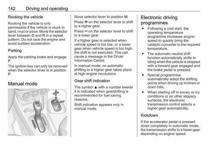
142 Driving and operating
Rocking the vehicleRocking the vehicle is onlypermissible if the vehicle is stuck insand, mud or snow. Move the selectorlever between D and R in a repeatpattern. Do not race the engine andavoid sudden acceleration.
ParkingApply the parking brake and engageP.The ignition key can only be removedwhen the selector lever is in positionP.
Manual mode
Move selector lever to position M.Press < on the selector lever to shiftto a higher gear.Press ] on the selector lever to shiftto a lower gear.If a higher gear is selected whenvehicle speed is too low, or a lowergear when vehicle speed is too high,the shift is not executed. This cancause a message in the DriverInformation Centre.In manual mode, no automaticshifting to a higher gear takes placeat high engine revolutions.
Gear shift indicationThe symbol R with a number besideit is indicated when gearshifting isrecommended for fuel savingreasons.Shift indication appears only inmanual mode.
Electronic drivingprogrammes● Following a cold start, the
operating temperatureprogramme increases enginespeed to quickly bring thecatalytic converter to the requiredtemperature.
● The automatic neutral shiftfunction automatically shifts toidling when the vehicle is stoppedwith a forward gear engaged andthe brake pedal is pressed.
● Special programmesautomatically adapt the shiftingpoints when driving up inclines ordown hills.
● When starting off in snowy or icyconditions or on other slipperysurfaces, the electronictransmission control selects ahigher gear automatically.
KickdownIf the accelerator pedal is presseddown completely in automatic mode,the transmission shifts to a lower geardepending on engine speed.
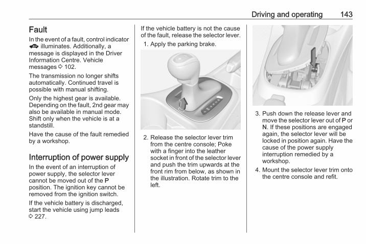
Driving and operating 143
FaultIn the event of a fault, control indicatorg illuminates. Additionally, amessage is displayed in the DriverInformation Centre. Vehiclemessages 3 102.The transmission no longer shiftsautomatically. Continued travel ispossible with manual shifting.Only the highest gear is available.Depending on the fault, 2nd gear mayalso be available in manual mode.Shift only when the vehicle is at astandstill.Have the cause of the fault remediedby a workshop.
Interruption of power supplyIn the event of an interruption ofpower supply, the selector levercannot be moved out of the Pposition. The ignition key cannot beremoved from the ignition switch.If the vehicle battery is discharged,start the vehicle using jump leads3 227.
If the vehicle battery is not the causeof the fault, release the selector lever.1. Apply the parking brake.
2. Release the selector lever trimfrom the centre console; Pokewith a finger into the leathersocket in front of the selector leverand push the trim upwards at thefront rim from below, as shown inthe illustration. Rotate trim to theleft.
3. Push down the release lever andmove the selector lever out of P orN. If these positions are engagedagain, the selector lever will belocked in position again. Have thecause of the power supplyinterruption remedied by aworkshop.
4. Mount the selector lever trim ontothe centre console and refit.

144 Driving and operating
Manual transmission
To engage reverse, depress theclutch pedal and then press therelease button on the selector leverand engage the gear.If the gear does not engage, set thelever to neutral, release the clutchpedal and depress again; then repeatgear selection.Do not slip the clutch unnecessarily.When operating, depress the clutchpedal completely. Do not use thepedal as a foot rest.
Caution
It is not advisable to drive with thehand resting on the selector lever.
Gear shift indication 3 92.Stop-start system 3 135.
Manual transmissionautomatedThe automated manual transmissionpermits manual gearshifting (manualmode) or automatic gearshifting(automatic mode), both withautomatic clutch control.Manual shifting is possible by tappingthe selector lever in manual mode.NoticeWhen unlocking or opening avehicle door, a sound may beaudible caused by the hydraulicsystem.

Driving and operating 145
Transmission display
In automatic mode, the drivingprogramme is indicated by D in theDriver Information Centre.In manual mode, M and the numberof the selected gear is indicated.R indicates reverse gear.N indicates neutral.
Starting the engineTo start the engine, depress the brakepedal, if transmission is not in positionN.
Transmission automatically shifts toN upon starting. There may be a slightdelay.Starting is not possible if all brakelights fail.
Stop-start-systemAutostopIf the vehicle is at a standstill andbrake pedal is operated, Autostop isactivated automatically.The engine will be switched off whilethe ignition stays on.
An Autostop is indicated by controlindicator D.AutostartRelease the brake pedal or moveselector lever out of D to restart theengine.
When the engine is restarted, controlindicator D extinguishes in the DriverInformation Centre.The stop-start system will be disabledon inclines of 15% or more.Stop-start-system 3 135.
Selector lever
Always move the selector lever in theappropriate direction as far as it willgo. Upon release, it automaticallyreturns to the centre position.

146 Driving and operating
N : neutral positionD/M : switch between automatic (D)
and manual (M) shift mode.The transmission displayshows either D or M with theselected gear
< : upshifting in manual mode] : downshifting in manual modeR : reverse gear. Engage only
when vehicle is stationary
If selector lever is moved from R to theleft, D is directly engaged.If selector lever is moved from D to< or ], manual mode M is selectedand the transmission shifts.
Starting offDepress the brake pedal and movethe selector lever to D/M or R. If D isselected, transmission is in automaticmode and first gear is engaged. If Ris selected, reverse gear is engaged.The vehicle starts to move when thebrake pedal is released.To start-off without depressing thebrake pedal, accelerate immediatelyafter engaging a gear as long as D orR flashes.
If neither the accelerator nor thebrake pedal are depressed, no gearis engaged and D or R flashes for abrief time in the display.
Stopping the vehicleIn D, first gear is engaged and theclutch is released when the vehicle isstopped. In R, reverse gear remainsengaged.
Engine braking
Automatic modeWhen driving downhill, the manualtransmission automated does notshift into higher gears until a fairlyhigh engine speed has been reached.It shifts down in good time whenbraking.
Manual modeTo utilise the engine braking effect,select a lower gear in good time whendriving downhill. Changing intomanual mode is only possible whilethe engine is running or during anAutostop.
Rocking the vehicleRocking the vehicle is onlypermissible if the vehicle is stuck insand, mud or snow. Move the selectorlever between R and D in a repeatpattern. Do not race the engine andavoid sudden acceleration.
ParkingThe most recently engaged gear (seetransmission display) remainsengaged when switching off ignition.With N, no gear is engaged.Therefore always apply the parkingbrake when switching off ignition. Ifparking brake is not applied, P flashesin the transmission display and thekey cannot be removed from theignition switch. P stops flashing in thetransmission display as soon as theparking brake is slightly applied.When the ignition is switched off, thetransmission no longer responds tomovement of the selector lever.

Driving and operating 147
Tyre pressure monitoring systemTo start the sensor matching processof the tyre pressure monitoringsystem, the selector lever must bemoved and held in position N forfive seconds. P illuminates in thetransmission display to indicate thatthe sensor matching process can bestarted.Tyre pressure monitoring system3 212.
Manual modeIf a higher gear is selected when theengine speed is too low, or a lowergear when the speed is too high, theshift is not executed. This preventsthe engine from running at too low ortoo high an engine speed. A warningmessage is displayed in the DriverInformation Centre. Vehiclemessages 3 102.If engine speed is too low, thetransmission automatically shifts to alower gear.If engine speed is too high, thetransmission only switches to a highergear via kickdown.
When + or - is selected in automaticmode, the transmission switches tomanual mode and shifts accordingly.
Gear shift indicationThe symbol R with a numberalongside it, is indicated whengearshifting is recommended for fuelsaving reasons.Shift indication appears only inmanual mode.
Electronic drivingprogrammes● Following a cold start, the
operating temperatureprogramme increases enginespeed to quickly bring thecatalytic converter to the requiredtemperature.
● The adaptive programme tailorsgearshifting to the drivingconditions, e.g. greater load orgradients.
KickdownIf the accelerator pedal is presseddown completely in automatic mode,the transmission shifts to a lower geardepending on engine speed.
FaultTo prevent damage to the manualtransmission automated, the clutch isengaged automatically at high clutchtemperatures.In the event of a fault, control indicatorg illuminates. Additionally, awarning message is displayed in theDriver Information Centre. Vehiclemessages 3 102.Continued driving is restricted or notpossible, depending on the fault.Have the cause of the fault remediedby a workshop.
148 Driving and operating
BrakesThe brake system comprises twoindependent brake circuits.If a brake circuit fails, the vehicle canstill be braked using the other brakecircuit. However, braking effect isachieved only when the brake pedalis depressed firmly. Considerablymore force is needed for this. Thebraking distance is extended. Seekthe assistance of a workshop beforecontinuing the journey.When the engine is not running, thesupport of the brake servo unitdisappears once the brake pedal hasbeen depressed once or twice.Braking effect is not reduced, butbraking requires significantly greaterforce. It is especially important to bearthis in mind when being towed.Control indicator R 3 92.
Antilock brake systemAntilock brake system (ABS)prevents the wheels from locking.
ABS starts to regulate brake pressureas soon as a wheel shows a tendencyto lock. The vehicle remainssteerable, even during hard braking.ABS control is made apparentthrough a pulse in the brake pedaland the noise of the regulationprocess.For optimum braking, keep the brakepedal fully depressed throughout thebraking process, despite the fact thatthe pedal is pulsating. Do not reducethe pressure on the pedal.After starting-off the system performsa self-test which may be audible.Control indicator u 3 92.
Adaptive brake lightDuring full braking, all three brakelights flash for the duration of ABScontrol.
Fault
9 Warning
If there is a fault in the ABS, thewheels may be liable to lock dueto braking that is heavier thannormal. The advantages of ABSare no longer available. Duringhard braking, the vehicle can nolonger be steered and mayswerve.
Have the cause of the fault remediedby a workshop.

Driving and operating 149
Parking brakeManual parking brake
9 Warning
Always apply parking brake firmlywithout operating the releasebutton, and apply as firmly aspossible on a downhill or uphillslope.To release the parking brake, pullthe lever up slightly, press therelease button and fully lower thelever.
To reduce the operating forces ofthe parking brake, depress thebrake pedal at the same time.
Control indicator R 3 92.
Brake assistIf the brake pedal is depressedquickly and forcefully, maximumbrake force is automatically applied(full braking).Maintain steady pressure on thebrake pedal for as long as full brakingis required. Maximum brake force isautomatically reduced when thebrake pedal is released.
Hill start assistThe system helps prevent unintendedmovement when driving away oninclines.When releasing the brake pedal afterstopping on an incline, the brakesremain on for a further two seconds.The brakes release automatically as
soon as the vehicle begins toaccelerate or the two seconds holdingtime is over.The hill start assist is not active duringan Autostop.

150 Driving and operating
Ride control systemsTraction Control systemThe Traction Control system (TC) is acomponent of the Electronic StabilityControl (ESC).TC improves driving stability whennecessary, regardless of the type ofroad surface or tyre grip, bypreventing the drive wheels fromspinning.As soon as the drive wheels start tospin, engine output is reduced andthe wheel spinning the most is brakedindividually. This considerablyimproves the driving stability of thevehicle on slippery road surfaces.
TC is operational after each enginestart as soon as the control indicatorb extinguishes.When TC operates b flashes.
9 Warning
Do not let this special safetyfeature tempt you into taking riskswhen driving.Adapt speed to the roadconditions.
Deactivation
TC can be switched off when spinningof drive wheels is required: press bbriefly.A status message appears in theDriver Information Centre when TC isdeactivated.
Control indicator k illuminates.When TC is deactivated, ESCremains active but with higher controlthreshold.TC is reactivated by pressing bagain. A status message pops-up inthe Driver Information Centre whenTC is reactivated.TC is also reactivated the next timethe ignition is switched on.
FaultIf there is a fault in the system thecontrol indicator b illuminatescontinuously and a message or awarning code appears in the DriverInformation Centre. The system is notoperational.Have the cause of the fault remediedby a workshop.

Driving and operating 151
Electronic Stability ControlElectronic Stability Control (ESC)improves driving stability whennecessary, regardless of the type ofroad surface or tyre grip.As soon as the vehicle starts toswerve (understeer/oversteer),engine output is reduced and thewheels are braked individually.ESC operates in combination with theTraction Control system (TC). Itprevents the drive wheels fromspinning.
ESC is operational after each enginestart as soon as the control indicatorb extinguishes.When ESC operates b flashes.
9 Warning
Do not let this special safetyfeature tempt you into taking riskswhen driving.Adapt speed to the roadconditions.
Control indicator b 3 93.
Deactivation
ESC and TC can be deactivated:● press and hold b for a minimum
of five seconds: ESC and TC areboth deactivated. k and n
illuminate and status messagesappear in the Driver InformationCentre.
● To deactivate only Tractioncontrol system, press b briefly:TC is inactive but ESC remainsactive with higher controlthreshold, k illuminates. A statusmessage appears in the DriverInformation Centre when TC isdeactivated.
ESC is reactivated by pressing theb button again. If the TC system waspreviously disabled, both TC andESC are reactivated. k and nextinguish when TC and ESC arereactivated.ESC is also reactivated the next timethe ignition is switched on.

152 Driving and operating
FaultIf there is a fault in the system, thecontrol indicator b illuminatescontinuously and a message or awarning code appears in the DriverInformation Centre. The system is notoperational.Have the cause of the fault remediedby a workshop.
City modeCity mode is a feature which enablesincreased steering assistance duringlower speed conditions, e.g. citytraffic or parking. Steering assistanceis increased for greater convenience.
Activation
Press B when engine is running. Thesystem works from standstill up to22 mph, and also in reverse gear.Above this speed, the systemchanges to normal mode. Whenactivated, City mode engagesautomatically below 22 mph.An illuminated LED in the City modebutton indicates that the system isactive and a message pops-up in theDriver Information Centre.City mode remains active during anAutostop, but is only operationalwhen the engine is running.Stop-start system 3 135.
DeactivationPress B; LED in the buttonextinguishes and a message pops-upin the Driver Information Centre.Each time the engine is started, Citymode is deactivated.
Fault
In the event of a fault in the system,control indicator c illuminates and amessage is displayed in the DriverInformation Centre.Vehicle messages 3 102.
System calibrationIf control indicators c and billuminate simultaneously, acalibration of the power steeringsystem is necessary. This can occure.g. when turning the steering wheelfor one rotation with ignition switched

Driving and operating 153
off. In this case, switch on ignition andturn steering wheel once from lock tolock.If control indicators c and b do notextinguish after calibration, seek theassistance of a workshop.
Driver assistancesystems
9 Warning
Driver assistance systems aredeveloped to support the driverand not to replace the driver'sattention.The driver accepts fullresponsibility when driving thevehicle.When using driver assistancesystems, always take careregarding the current trafficsituation.
Cruise controlThe cruise control can store andmaintain speeds of approx. 20 mph tomaximum vehicle speed. Deviationsfrom the stored speeds may occurwhen driving uphill or downhill.For safety reasons, the cruise controlcannot be activated until the brakepedal has been operated once.Activating in first gear is not possible.
Do not use the cruise control if it is notadvisable to maintain a constantspeed.On vehicles with automatictransmission or manual transmissionautomated cruise control can beactivated in automatic mode andmanual mode.Control indicator m 3 95.

154 Driving and operating
Switching on
Press m; control indicator m ininstrument cluster illuminates white.
ActivationAccelerate to the desired speed andturn thumb wheel to SET/-, thecurrent speed is stored andmaintained. Control indicator m ininstrument cluster illuminates green.Set speed is indicated on the display.Accelerator pedal can be released.Vehicle speed can be increased bydepressing the accelerator pedal.When the accelerator pedal isreleased, the previously stored speedis resumed.Cruise control remains activatedwhile gearshifting.
Increase speedWith cruise control active, hold thumbwheel turned to RES/+ or briefly turnto RES/+ repeatedly: speedincreases continuously or in smallincrements.Alternatively accelerate to the desiredspeed and store by turning to SET/-.
Reduce speedWith cruise control active, hold thumbwheel turned to SET/- or briefly turn toSET/- repeatedly: speed decreasescontinuously or in small increments.
DeactivationPress y; control indicator m ininstrument cluster illuminates white.Cruise control is deactivated. Laststored speed remains in memory forlater speed resume.Automatic deactivation:● Vehicle speed is below approx.
20 mph.● Vehicle speed drops more than
15 mph below the set speed.● The brake pedal is depressed.● The clutch pedal is depressed for
a few seconds.● The selector lever is in N.● Engine speed is in a very low
range.● The Traction Control system or
Electronic Stability Control isoperating.
● Parking brake is applied.● Simultaneous pressing RES/+
and brake pedal deactivatescruise control and will deletestored speed.

Driving and operating 155
Resume stored speedTurn thumb wheel to RES/+ at aspeed above 20 mph. The storedspeed will be obtained.
Switching offPress m, control indicator m ininstrument cluster extinguishes. Thestored speed is deleted.Pressing L to activate the speedlimiter or switching off the ignition alsoswitches off cruise control anddeletes the stored speed.
Speed limiterThe speed limiter prevents thevehicle exceeding a preset maximumspeed.The maximum speed can be set atspeeds above 15 mph up to125 mph.The driver can only accelerate up tothe preset speed. Deviations from thelimited speed may occur when drivingdownhill.
The preset speed limit is displayed inthe Driver Information Centre whenthe system is active.
Activation
Press L. If cruise control has beenactivated before, it is switched offwhen speed limiter is activated andcontrol indicator m extinguishes.
Set speed limitAccelerate to the desired speed andbriefly turn thumb wheel to SET/-: thecurrent speed is stored as maximumspeed. Speed limit is displayed in theDriver Information Centre.
Change speed limitWith speed limiter active, turn thumbwheel to RES/+ to increase or SET/-to decrease the desired maximumspeed.
Exceeding the speed limitWhen exceeding the limited speedwithout driver input, the speed willflash in the Driver Information Centreand a chime sounds during thisperiod.In the event of an emergency, it ispossible to exceed the speed limit bydepressing the accelerator pedalfirmly nearly to the final point. In thiscase no chime appears.Release the accelerator pedal andthe speed limiter function isreactivated once a speed lower thanthe limit speed is obtained.

156 Driving and operating
DeactivationPress y: speed limiter is deactivatedand the vehicle can be driven withoutspeed limit.The limited speed will be stored andis indicated in brackets in the DriverInformation Centre. Additionally, acorresponding message appears.
Resume limit speedTurn thumb wheel to RES/+. Thestored speed limit will be obtained.
Switching offPress L, the speed limit indicationextinguishes in the Driver InformationCentre. The stored speed is deleted.By pressing m to activate cruisecontrol, speed limiter is alsodeactivated and the stored speed isdeleted.By switching off the ignition, speedlimiter is also deactivated, but thespeed limit will be stored for nextspeed limiter activation.
Forward collision alertThe forward collision alert can help toavoid or reduce the harm caused byfront-end crashes.Forward collision alert uses the frontcamera system in the windscreen todetect a vehicle directly ahead, inyour path, within a distance of approx.60 metres.
A vehicle ahead is indicated bycontrol indicator A.If a vehicle directly ahead isapproached too quickly, a warningchime and alert in the DriverInformation Centre is provided.Additionally the driver gets notified bya flashing red LED stripe which isprojected on the windscreen in thedriver's field of view.
A precondition is that forward collisionalert is not deactivated by pressingV.
ActivationForward collision alert operatesautomatically above 25 mph, if it is notdeactivated by pressing V, seebelow.
Selecting the alert sensitivityThe alert sensitivity can be set tonear, medium or far.

Driving and operating 157
Press V, the current setting is shownon the Driver Information Centre.Press V repeatedly to change thealert sensitivity. The selected settingis also displayed in the DriverInformation Centre.
Alerting the driverThe vehicle ahead control indicatorA illuminates green in the instrumentcluster when the system has detecteda vehicle in the driving path.
Caution
The colour lighting of this controlindicator does not correspond tolocal traffic laws on followingdistance. The driver bears fullresponsibility for maintaining safefollowing distance according toapplicable traffic rules, weatherand road conditions etc. at alltimes.
When the time to a potential collisionwith a vehicle in front gets too smalland a collision is imminent, thecollision alert symbol pops-up in theDriver Information Centre and thedriver gets notified by a flashing redLED stripe which is projected on thewindscreen in the driver's field ofview.
Simultaneously a warning chimesounds. Depress the brake pedal andsteer the vehicle, if it is required by thesituation.
DeactivationThe system can be deactivated.Press V repeatedly until the followingmessage appears in the DriverInformation Centre.

158 Driving and operating
If the forward collision alert wasdeactivated, alert sensitivity is set to"medium" when ignition is switchedon next time.The settings "near", "medium" or "far"will be stored when the ignition isswitched off.
General information
9 Warning
Forward collision alert is just awarning system and does notapply the brakes. When
approaching a vehicle ahead toorapidly, it may not provide youenough time to avoid a collision.The driver accepts fullresponsibility for the appropriatefollowing distance based on traffic,weather and visibility conditions.The complete attention of thedriver is always required whiledriving. The driver must always beready to take action and apply thebrakes.
System limitationsThe system is designed to warn ofvehicles only, but may react also toother objects.In the following cases, forwardcollision alert may not detect a vehicleahead or sensor performance islimited:● on winding roads● when weather limits visibility, e.g.
fog, rain, or snow● when the sensor is blocked by
snow, ice, slush, mud, dirt,windscreen damage or affectedby foreign items, e.g. stickers
Following distanceindicationThe following distance indicationdisplays the distance to a precedingmoving vehicle. The front camera inthe windscreen is used to detect thedistance of a vehicle directly ahead inthe vehicle's path. It is active atspeeds above 25 mph.When a preceding vehicle is detectedahead, the distance is indicated inseconds, displayed on a page in theDriver Information Centre 3 96. PressMENU on the turn signal lever toselect ? and turn the adjusterwheel to choose following distanceindication page.

Driving and operating 159
The minimum indicated distance is0.5 seconds.If there is no vehicle ahead or thevehicle ahead is out of range, twodashes will be displayed: -.- sec.
Parking assistRear parking assist
9 Warning
It is the driver who bears fullresponsibility for the parkingmanoeuvre.
Always check the surroundingarea while reversing and using therear parking assist system.
The rear parking assist makesparking easier by measuring thedistance between the vehicle andrear obstacles. It informs and warnsthe driver by giving acoustic signalsand display indication.
The system has four ultrasonicparking sensors in the rear bumper.
ActivationWhen reverse gear is engaged, thesystem is ready to operateautomatically.
An illuminated LED in the parkingassist button r indicates that thesystem is ready to operate.
IndicationThe system warns the driver withacoustic signals against potentiallyhazardous obstacles behind thevehicle in a distance range up to1.5 metres. The interval between thesounds becomes shorter as thevehicle gets closer to that obstacle.When the distance is less thanapprox. 30 cm, the sound iscontinuous.Additionally, the distance to rearobstacles is displayed by changingdistance lines in the DriverInformation Centre 3 96 or,depending on the version, on theColour-Info-Display 3 100.The distance indication can beinhibited by vehicle messages with ahigher priority. After approving themessage by pressing SET/CLR onthe turn signal lever, distanceindication appears again.

160 Driving and operating
Deactivation
The system automatically switchesoff when reverse gear is disengaged.Manual deactivation is also possibleby pressing the parking assist buttonr.In both cases, the LED in the buttonextinguishes.
FaultIn the event of a fault or if the systemdoes not work temporarily, e.g.because of high external noise levelor other interference factors, the LEDin the button flashes forthree seconds then extinguishes.
Control indicator r illuminates inthe instrument cluster 3 93 or amessage is indicated in the DriverInformation Centre.
Front-rear parking assist
9 Warning
The driver bears full responsibilityfor the parking manoeuvre.Always check the surroundingarea when driving backwards orforwards while using parkingassist system.
The front-rear parking assistmeasures the distance between thevehicle and obstacles in front andbehind the vehicle. It informs andwarns the driver by giving acousticsignals and display indication.It uses two different acoustic warningsignals for the front and rearmonitoring areas, each with adifferent tone frequency.
The system has four ultrasonicparking sensors each in the rear andfront bumper.
ActivationThe system is activated automaticallyat a speed up to 7 mph.

Driving and operating 161
An illuminated LED in the parkingassist button r indicates that thesystem is ready to operate.If r is switched off within an ignitioncycle, the front parking assist isdeactivated. If vehicle speed hasexceeded 15 mph beforehand,parking assist will be reactivatedwhen speed drops below 7 mph.When the system is deactivated, theLED in the button extinguishes andPark Assist Off pops-up in the DriverInformation Centre.
IndicationThe system warns the driver withacoustic signals against potentiallyhazardous obstacles in front of thevehicle in a distance range up to 80cm and against potentially hazardousobstacles behind the vehicle in adistance range up to 1.5 metres.Depending on which side of thevehicle is closer to an obstacle, youwill hear acoustic warning signals inthe vehicle on the respective side.The interval between the soundsbecomes shorter as the vehicle getscloser to that obstacle. When thedistance is less than approx. 30 cm,the sound is continuous.Additionally, the distance to rear andfront obstacles is displayed bychanging distance lines in the DriverInformation Centre 3 96 or,depending on the version, on theColour-Info-Display 3 100.
The distance indication can beinhibited by vehicle messages with ahigher priority. After dismissing themessage distance indication appearsagain.

162 Driving and operating
The distance to obstacles is shown onthe Colour-Info-Display by colouredzones in front of or behind the vehicle3 100.
DeactivationThe system is deactivatedautomatically when vehicle speedexceeds 7 mph.Manual deactivation is also possibleby pressing the parking assist buttonr.When the system is deactivated, theLED in the button extinguishes and, ifmanually deactivated, Park AssistOff pops-up in the Driver InformationCentre.After a manual deactivation, the front-rear parking assist is activated againif r is pressed.The complete system can bemanually deactivated in the vehiclepersonalisation menu in theInfo-Display. It remains deactivatedduring the ignition cycle or untilactivation in personalisation menuagain. Vehicle personalisation 3 105.
When using the trailer hitch changethe configuration settings in thevehicle personalisation menu in theInfo-Display. Vehicle personalisation3 105.
FaultIn the event of a fault or if the systemdoes not work temporarily, e.g.because of high external noise levelor other interference factors, amessage pops-up in the DriverInformation Centre.Vehicle messages 3 102.
Advanced parking assist
9 Warning
The driver bears full responsibilityfor accepting the parking slotsuggested by the system and theparking manoeuvre.Always check the surroundingarea in all directions when usingthe advanced parking assist.
The advanced parking assistmeasures a suitable parking slotwhile passing, calculates the
trajectory and automatically steersthe vehicle into a parallel orperpendicular parking slot.Instructions are given in the DriverInformation Centre 3 96 or,depending on the version, on theColour-Info-Display 3 100, supportedby acoustic signals.The driver must control acceleration,braking and gear shifting, whilesteering is done automatically.
Advanced parking assist is alwayscombined with front-rear parkingassist. Both systems use the samesensors in the front and rear bumper.
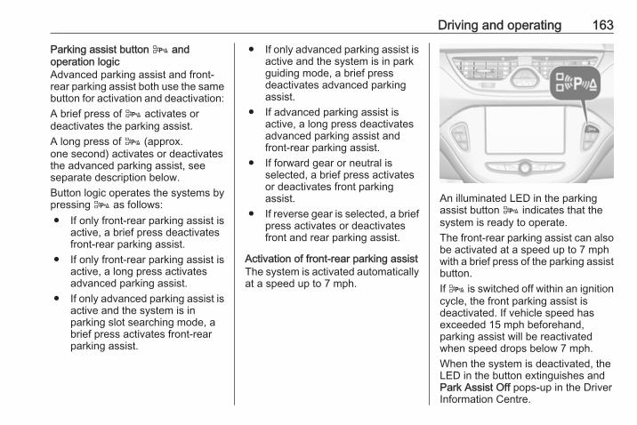
Driving and operating 163
Parking assist button D andoperation logicAdvanced parking assist and front-rear parking assist both use the samebutton for activation and deactivation:A brief press of D activates ordeactivates the parking assist.A long press of D (approx.one second) activates or deactivatesthe advanced parking assist, seeseparate description below.Button logic operates the systems bypressing D as follows:● If only front-rear parking assist is
active, a brief press deactivatesfront-rear parking assist.
● If only front-rear parking assist isactive, a long press activatesadvanced parking assist.
● If only advanced parking assist isactive and the system is inparking slot searching mode, abrief press activates front-rearparking assist.
● If only advanced parking assist isactive and the system is in parkguiding mode, a brief pressdeactivates advanced parkingassist.
● If advanced parking assist isactive, a long press deactivatesadvanced parking assist andfront-rear parking assist.
● If forward gear or neutral isselected, a brief press activatesor deactivates front parkingassist.
● If reverse gear is selected, a briefpress activates or deactivatesfront and rear parking assist.
Activation of front-rear parking assistThe system is activated automaticallyat a speed up to 7 mph.
An illuminated LED in the parkingassist button D indicates that thesystem is ready to operate.The front-rear parking assist can alsobe activated at a speed up to 7 mphwith a brief press of the parking assistbutton.If D is switched off within an ignitioncycle, the front parking assist isdeactivated. If vehicle speed hasexceeded 15 mph beforehand,parking assist will be reactivatedwhen speed drops below 7 mph.When the system is deactivated, theLED in the button extinguishes andPark Assist Off pops-up in the DriverInformation Centre.
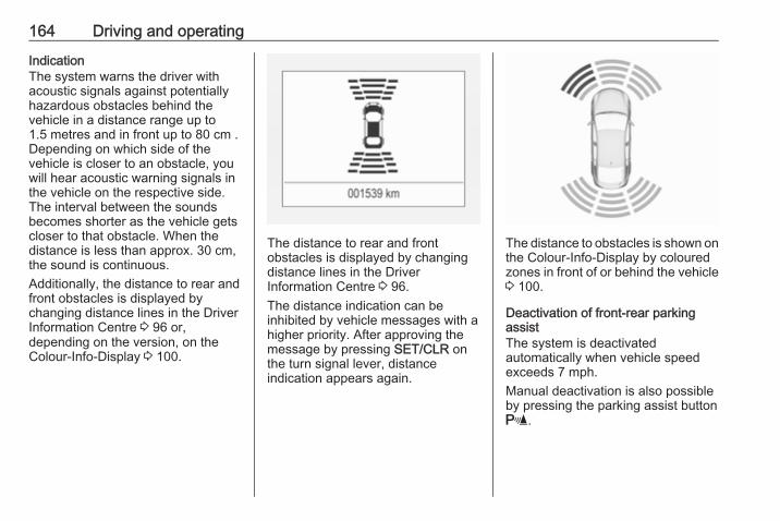
164 Driving and operating
IndicationThe system warns the driver withacoustic signals against potentiallyhazardous obstacles behind thevehicle in a distance range up to1.5 metres and in front up to 80 cm .Depending on which side of thevehicle is closer to an obstacle, youwill hear acoustic warning signals inthe vehicle on the respective side.The interval between the soundsbecomes shorter as the vehicle getscloser to that obstacle. When thedistance is less than approx. 30 cm,the sound is continuous.Additionally, the distance to rear andfront obstacles is displayed bychanging distance lines in the DriverInformation Centre 3 96 or,depending on the version, on theColour-Info-Display 3 100.
The distance to rear and frontobstacles is displayed by changingdistance lines in the DriverInformation Centre 3 96.The distance indication can beinhibited by vehicle messages with ahigher priority. After approving themessage by pressing SET/CLR onthe turn signal lever, distanceindication appears again.
The distance to obstacles is shown onthe Colour-Info-Display by colouredzones in front of or behind the vehicle3 100.
Deactivation of front-rear parkingassistThe system is deactivatedautomatically when vehicle speedexceeds 7 mph.Manual deactivation is also possibleby pressing the parking assist buttonr.

Driving and operating 165
When the system is deactivated, theLED in the button extinguishes and, ifmanually deactivated, Park AssistOff pops-up in the Driver InformationCentre.After a manual deactivation, the front-rear parking assist is activated againif r is pressed.The complete system can bemanually deactivated in the vehiclepersonalisation menu in theInfo-Display. It remains deactivatedduring the ignition cycle or untilactivation in personalisation menuagain. Vehicle personalisation 3 105.When using the trailer hitch changethe configuration settings in thevehicle personalisation menu in theInfo-Display. Vehicle personalisation3 105.
Activation of advanced parking assistAdvanced parking assist can only beactivated when driving forwards.
When searching for a parking slot, thesystem is ready to operate with a longpress of D.The system recognises andmemorises ten metres for parallelparking slots or six metres forperpendicular parking slots in theparking assist mode.The system can only be activated ata speed up to 18 mph and the systemsearches for a parking slot at a speedup to 18 mph.The maximum allowed paralleldistance between the vehicle and arow of parked cars is 1.8 metres forparallel parking and 2.5 metres forperpendicular parking.
FunctionalityParking slot searching modeIndication in the Driver InformationCentre

166 Driving and operating
Select parallel or perpendicularparking slot in Driver InformationCentre by pressing SET/CLR.The system is configured to detectparking slots by default on thepassenger side. To detect parkingslots on the driver side, switch on turnsignal indicator on the driver side.
When a slot is detected, visualfeedback in the Driver InformationCentre and an acoustic signal isgiven.Indication in the Colour-Info-Display
Select parallel or perpendicularparking slot by tapping the respectiveicon on the display.Select parking side by tapping therespective icon on the display.
When a slot is detected, a visualfeedback on the Colour-Info-Displayand an acoustic signal is given.If the driver does not stop the vehicleafter a parking slot is proposed, thesystem starts to search for anothersuitable parking slot.Park guiding modeThe parking slot suggestion of thesystem is accepted when the vehicleis stopped by the driver within10 metres for parallel parking slots orsix metres for perpendicular parkingslots after the Stop message is given.The system calculates the optimalpath into the parking slot.A brief vibration in the steering wheelafter engaging reverse gear indicatesthat the steering is controlled by thesystem. Then the vehicle is steeredinto the slot automatically by givingthe driver detailed instructions forbraking, accelerating and gearshifting. The driver must keep handsaway from the steering wheel.

Driving and operating 167
Always pay attention to the sound ofthe front-rear parking assist.Continuous sound indicates that thedistance to an obstacle is less thanapprox. 30 cm.If, for any reason, the driver must takeover control of the steering, hold thesteering wheel only at the outer edge.Automatic steering is cancelled in thisevent.Display indicationThe instructions on the display show:● General hints and warning
messages.● A hint when driving faster than
18 mph during parking slotsearching mode, or 5 mph inguiding mode.
● The demand to stop the vehicle,when a parking slot is detected.
● The direction of driving during theparking manoeuvre.
● The demand to shift into reverseor first gear.
● The demand to accelerate orbrake.
● For some of the instructions aprogress bar is shown in theDriver Information Centre.
● The successful completion of theparking manoeuvre indicated bya pop-up symbol and a chime.
● The cancelling of a parkingmanoeuvre.
Display prioritiesAdvanced parking assist indication inthe Driver Information Centre can beinhibited by vehicle messages with ahigher priority. After approving themessage by pressing SET/CLR onthe turn signal lever, advancedparking assist instructions appearagain and the parking manoeuvre canbe continued.
DeactivationThe system is deactivated by:● a long press of D● parking manoeuvre successfully
ended
● driving faster than 18 mph duringparking slot search
● driving faster than 5 mph duringparking guidance
● driver interference on steeringwheel detected
● exceeding number of maximumgear changes: eight cycles whenparallel parking or five cycleswhen perpendicular parking
● switching off the ignitionDeactivation by the driver or by thesystem during manoeuvring will beindicated by Parking Deactivated onthe display. Additionally, an acousticsignal sounds.
FaultA message appears when:● There is a fault in the system.● The driver did not successfully
complete the parkingmanoeuvre.
● The system is not operational.● Any of the deactivation reasons
described above apply.

168 Driving and operating
If an object is detected during parkinginstructions, Stop is indicated on thedisplay. Removing the object willresume the parking manoeuvre. If theobject is not removed, the system willbe deactivated. A long press of Dwill activate the system and search fora new parking slot.
Basic notes on parking assistsystems
9 Warning
Under certain circumstances,various reflective surfaces onobjects or clothing as well asexternal noise sources may causethe system to fail to detectobstacles.Special attention must be paid tolow obstacles which can damagethe lower part of the bumper.
Caution
Performance of the system can bereduced when sensors arecovered, e.g. by ice or snow.Performance of the parking assistsystem can be reduced due toheavy loading.Special conditions apply if thereare taller vehicles in the vicinity(e.g. off-road vehicles, mini vans,vans). Object identification andcorrect distance indication in theupper part of these vehiclescannot be guaranteed.Objects with a very small reflectioncross-section, e.g. objects ofnarrow size or soft materials, maynot be detected by the system.Parking assist systems do notdetect objects outside thedetection range.
NoticeIt is possible that the sensor detectsa non-existing object caused byecho disturbance from external
acoustic noise or mechanicalmisalignments (sporadic falsewarnings may occur).Make sure that the front numberplate is properly mounted (not bentand no gaps to the bumper on the leftor right side) and the sensors arefirmly in place.Advanced parking assist systemmay not respond to changes in theavailable parking space afterinitiating a parking manoeuvre. Thesystem may recognize an entry, agateway, a courtyard or even acrossing as a parking slot. Afterselecting reverse gear the systemwill start a parking manoeuvre. Takecare regarding the availability of thesuggested parking slot.Surface irregularities, e.g. onconstruction zones, are not detectedby the system. The driver acceptsresponsibility.

Driving and operating 169
NoticeIf engaging a forward gear andexceeding a certain speed, the rearparking assist will be deactivatedwhen the rear carrier system isextended.If engaging reverse at first, theparking assist will detect the rearcarrier system and provide a buzzingsound. Press r or D briefly todeactivate the parking assist.NoticeAfter production, the systemrequires a calibration. For optimalparking guidance, a driving distanceof at least 6 miles, including anumber of bends, is required.
Side blind spot alertThe Side blind spot alert systemdetects and reports objects on eitherside of the vehicle, within a specified"blind spot" zone. The system alertsvisually in each exterior mirror, whendetecting objects that may not bevisible in the interior and exteriormirrors.
Side blind spot alert uses some of theadvanced parking assist sensorswhich are located in the front and rearbumper on both sides of the vehicle.
9 Warning
Side blind spot alert does notreplace driver vision.The system does not detect:
● vehicles outside the side blindzones which may be rapidlyapproaching
● pedestrians, cyclists or animalsBefore changing a lane, alwayscheck all mirrors, look over theshoulder and use the turn signal.
When the system detects a vehicle inthe side blind zone while drivingforward, either while passing avehicle or being passed, a yellowwarning symbol B will illuminate inthe relevant exterior mirror. If thedriver then activates the turn signal,the warning symbol B starts flashingyellow as a warning not to changelanes.
NoticeIf the passing vehicle is at least6 mph faster than the passedvehicle, the warning symbol B in therelevant exterior mirror may notilluminate.
Side blind spot alert is active fromspeeds of 6 mph up to 87 mph.Driving faster than 87 mphdeactivates the system, indicated bylow lighting warning symbols B inboth exterior mirrors. Reducing thespeed again will extinguish thewarning symbols. If a vehicle is thendetected in the blind zone, thewarning symbols B will illuminate asnormal on the relevant side.

170 Driving and operating
When the vehicle is started, bothexterior mirror displays will brieflycome on to indicate that the system isoperating.The system can be activated ordeactivated in the Info-Display,vehicle personalisation 3 105.Deactivation is indicated by amessage in the Driver InformationCentre.
Detection zonesThe detection zones start at the rearbumper and extend approx.three metres rearwards and to thesides. The height of the zone isapprox. between 0.5 metres andtwo metres off the ground.Side blind spot alert is designed toignore stationary objects, e.g.guardrails, posts, curbs, walls andbeams. Parked vehicles or oncomingvehicles are not detected.
FaultOccasional missed alerts can occurunder normal circumstances and willincrease in wet conditions.
Side blind spot alert does not operatewhen the left or right corners of therear bumper are covered with mud,dirt, snow, ice, slush, or in heavyrainstorms. Cleaning instructions3 231.In the event of a fault in the system orif the system does not work due totemporary conditions, a message isdisplayed in the Driver InformationCentre. Seek the assistance of aworkshop.
Rear view cameraThe rear view camera assists thedriver when reversing by displaying aview of the area behind the vehicle.The view of the camera is displayedin the Colour-Info-Display.
9 Warning
The rear view camera does notreplace driver vision. Note thatobjects that are outside thecamera's field of view and theadvanced parking assist sensors,
e.g. below the bumper orunderneath the vehicle, are notdisplayed.Do not reverse the vehicle by onlylooking at the Info-Display andcheck the surrounding areabehind and around the vehiclebefore reversing.
ActivationRear view camera is automaticallyactivated when reverse gear isengaged.
Functionality

Driving and operating 171
The camera is mounted between thenumber plate lights and has a viewingangle of 130°.
The area displayed by the camera islimited. The distance of the image thatappears on the display differs fromthe actual distance.
Warning symbolsWarning symbols are indicated astriangles 9 on the picture, which showobstacles detected by the rearsensors of the advanced parkingassist.Additionally 9 appears on the top lineof the Info-Display with the warning tocheck the vehicle surrounding.
Display settingsBrightness and contrast can be set bytapping the touch screen displaywhen rear view camera is active.
DeactivationThe camera is deactivated when acertain forward speed is exceeded orif reverse gear is not engaged forapprox. ten seconds.Rear view camera can be manuallydeactivated in the vehiclepersonalisation menu in theInfo-Display. Vehicle personalisation3 105.
Deactivation of guiding lines andwarning symbolsActivation or deactivation of the visualguiding lines and the warningsymbols can be changed by touchbuttons in the lower zone of thedisplay.
FaultFault messages are displayed with a9 on the top line of the Info-Display.
The rear view camera may notoperate properly when:● The surrounding is dark.● The sun or the beam of
headlights is shining directly intothe camera lens.
● Ice, snow, mud, or anything elsecovers the camera lens. Cleanthe lens, rinse it with water, andwipe it with a soft cloth.
● The vehicle is towing a trailer.● The vehicle had a rear end
accident.● There are extreme temperature
changes.
Traffic sign assistantFunctionalityThe traffic sign assistant systemdetects designated traffic signs via afront camera and displays them in theDriver Information Centre.
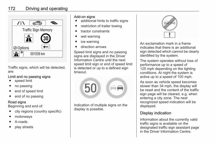
172 Driving and operating
Traffic signs, which will be detected,are:Limit and no passing signs● speed limit● no passing● end of speed limit● end of no passing
Road signsBeginning and end of:● city regions (country specific)● motorways● A-roads● play streets
Add-on signs● additional hints to traffic signs● restriction of trailer towing● tractor constraints● wet warning● ice warning● direction arrows
Speed limit signs and no passingsigns are displayed in the DriverInformation Centre until the nextspeed limit sign or end of speed limitis detected or up to a defined signtimeout.
Indication of multiple signs on thedisplay is possible.
An exclamation mark in a frameindicates that there is an additionalsign detected which cannot be clearlyidentified by the system.The system operates without loss ofperformance up to a speed of125 mph depending on the lightingconditions. At night the system isactive up to a speed of 100 mph.As soon as vehicle speed becomesslower than 34 mph, the display willbe reset and the content of the trafficsign page will be cleared, e.g. whenentering a city zone. The nextrecognized speed indication will bedisplayed.
Display indicationInformation about the currently validtraffic signs is available on thedesignated traffic sign assistant pagein the Driver Information Centre.

Driving and operating 173
Additionally, the currently valid speedlimit is displayed permanently in thelower line of the Driver InformationCentre. In case a speed limit withaddon is available, a + symbol isdisplayed in this area.
Choose ? via MENU and selecttraffic sign assistant page with theadjuster wheel on the turn signal lever3 96.When another page on the DriverInformation Centre menu wasselected and then traffic signassistant page is chosen again, thelast recognised traffic sign will bedisplayed.
Alert functionThe alert function can be activated ordeactivated in the setting menu of thetraffic sign assistant page.
Once activated and when the trafficsign detection page is currently notdisplayed, newly detected speed limitand no passing signs are displayedas popup alerts in the DriverInformation Centre.
When traffic sign assistant page isdisplayed, press SET/CLR on the turnsignal lever.

174 Driving and operating
Select Alerts ON or Alerts OFF byturning the adjuster wheel and pressSET/CLR.Pop-up alert is displayed for approx.eight seconds in the DriverInformation Centre.
System resetThe content of the traffic sign memorycan be cleared in the setting menu ofthe traffic sign assistant page byselecting Reset and confirm bypressing SET/CLR on the turn signallever.Alternatively, SET/CLR can bepressed for three seconds to clear thecontent of the page.Upon successful reset, a chime willsound and the following “DefaultSign” is indicated until the next trafficsign is detected.
In some cases, traffic sign assistant iscleared up automatically by thesystem.
Clearing of traffic signsThere are different scenarios thatlead to clearing the currentlydisplayed traffic signs. After clearing,the “Default Sign” is displayed in theDriver Information Centre.Reasons for signs being cleared:● A predefined distance was driven
or time has elapsed (differs foreach sign type)
● Vehicle drives through a turn● The speed becomes slower than
32 mph (city entry detection)
FaultThe traffic sign assistant system maynot operate correctly if:● The area of the windscreen,
where the front camera islocated, is not clean or affectedby foreign items, e.g. stickers.
● Traffic signs are completely orpartially covered or difficult todiscern.
● There are adverse environmentalconditions, e.g. heavy rain, snow,direct sunlight or shadows.
● Traffic signs are incorrectlymounted or damaged.
● Traffic signs do not comply withthe Vienna Convention on trafficsigns (Wiener Übereinkommenüber Straßenverkehrszeichen).
Caution
The system is intended to help thedriver within a defined speedrange to discern certain trafficsigns. Do not ignore traffic signswhich are not displayed by thesystem.The system does not discern anyother than the conventional trafficsigns that might give or end aspeed limit.Do not let this special featuretempt you into taking risks whendriving.Always adapt speed to the roadconditions.

Driving and operating 175
The driver assistance systems donot relieve the driver from fullresponsibility for vehicleoperation.
Lane departure warningThe lane departure warning systemobserves the lane markings betweenwhich the vehicle is driving via a frontcamera. The system detects lanechanges and warns the driver in theevent of an unintended lane changevia visual and acoustic signals.Criteria for the detection of anunintended lane change are:● No operation of turn signals.● No brake pedal operation.● No active accelerator operation
or speeding-up.● No active steering.
If the driver is performing theseactions, no warning will be issued.
Activation
The lane departure warning system isactivated by pressing ). Theilluminated LED in the buttonindicates that the system is switchedon. When control indicator ) in theinstrument cluster illuminates green,the system is ready to operate.The system is only operable atvehicle speeds above 35 mph and iflane markings are available.When the system recognises anunintended lane change, controlindicator ) changes to yellow andflashes. Simultaneously a chimesound is activated.
DeactivationThe system is deactivated bypressing ), LED in the buttonextinguishes.At speeds below 35 mph the systemis inoperable.
FaultThe lane departure warning systemmay not operate properly when:● The windscreen is not clean.● There are adverse environmental
conditions e.g. heavy rain, snow,direct sunlight or shadows.
The system can not operate when nolane marking is detected.

176 Driving and operating
FuelFuel for petrol enginesOnly use unleaded fuel that complieswith European standard EN 228 orE DIN 51626-1 or equivalent.The engine is capable of running withfuel that contains up to 10% ethanol(e.g. named E10).Use fuel with the recommendedoctane rating. The engine-specificrequirements are given in the enginedata overview 3 242. A country-specific label at the fuel filler flap cansupersede the requirement.
Caution
Do not use fuel or fuel additivesthat contain metallic compoundssuch as manganese-basedadditives. This may cause enginedamage.
Caution
Use of fuel that does not comply toEN 228 or E DIN 51626-1 orequivalent can lead to deposits orengine damage.
Caution
Use of fuel with too low an octanerating could lead to uncontrolledcombustion and engine damage.
Fuel for diesel enginesOnly use diesel fuel that complieswith EN 590.In countries outside the EuropeanUnion use Euro-Diesel fuel with asulphur concentration below 50 ppm.
Caution
Use of fuel that does not comply toEN 590 or similar can lead toengine powerloss, increased wearor engine damage.
Do not use marine diesel oils, heatingoils, Aquazole and similar diesel-water emulsions. Diesel fuels mustnot be diluted with fuels for petrolengines.
Fuel for liquid gas operationLiquid gas is known as LPG(Liquefied Petroleum Gas) or underits French name GPL (Gaz de PétroleLiquéfié). LPG is also known asAutogas.LPG consists mainly of propane andbutane. The octane rating is between105 and 115, depending on thebutane proportion. LPG is storedliquid at around five to ten barpressure.The boiling point depends on thepressure and mixing ratio. At ambientpressure, it is between -42 °C (purepropane) and -0.5 °C (pure butane).
Caution
The system works at an ambienttemperature of approx. -8 °C to100 °C.

Driving and operating 177
Full function of the LPG system canonly be guaranteed with liquid gaswhich complies with the minimumrequirements of DIN EN 589.
Fuel selector
Pressing LPG switches betweenpetrol and liquid gas operation assoon as the required parameters(coolant temperature, gastemperature and minimum enginespeed) have been reached. Therequirements are usually fulfilled afterapprox. 60 seconds (depending onexterior temperature) and the first firm
press on the accelerator. The LEDstatus shows the current operatingmode.LED off : petrol operationLEDflashes
: checking conditions forfuel transition to liquidgas operation.Illuminates if conditionsare fulfilled.
LED illu‐minates
: liquid gas operation
LEDflashesfivetimesandextin‐guishes
: liquid gas tank is emptyor failure in liquid gassystem. A message isdisplayed in the DriverInformation Centre.
If the fuel tank is empty, the enginewill not start.The selected fuel mode is stored andreactivated at the next ignition cycle ifconditions allow.As soon as the liquid gas tanks areempty, petrol operation isautomatically engaged until theignition is switched off.
When switching automaticallybetween petrol or gas operation, abrief delay of engine tractive powermay be noticeable.Every six months, run the petrol tankdown until control indicator Yilluminates, then refuel. This helpsmaintain fuel quality and systemfunction for petrol operation.Fill the tank completely at regularintervals to prevent corrosion in thetank.
Faults and remediesIf gas mode is not possible, check thefollowing:● Is there enough liquid gas
present?● Is there enough petrol present for
starting?Due to extreme temperatures incombination with the gascomposition, it may take slightlylonger before the system switchesfrom petrol to gas mode.In extreme situations, the system mayalso switch back to petrol mode if theminimum requirements are not

178 Driving and operating
fulfilled. If conditions allow, it might bepossible to manually switch back toliquid gas operation.Seek the assistance of a workshop inthe event of all other faults.
Caution
Repairs and adjustments may onlybe made by trained specialists inorder to maintain the safety andwarranty on the LPG system.
Liquid gas is given a particular odour(odorised) so that any leaks can bedetected easily.
9 Warning
If you smell gas in the vehicle or inthe immediate vicinity, switch topetrol mode immediately. Nosmoking. No naked flames orignition sources.
If the gas odour persists, do not startthe engine. Have the cause of thefault remedied by a workshop.
When using underground car parks,follow the instructions of the operatorand local laws.NoticeIn the event of an accident, switch offthe ignition and lights.
Refuelling
9 Danger
Before refuelling, switch offignition and any external heaterswith combustion chambers.
Follow the operating and safetyinstructions of the filling stationwhen refuelling.
9 Danger
Fuel is flammable and explosive.No smoking. No naked flames orsparks.If you can smell fuel in yourvehicle, have the cause of thisremedied immediately by aworkshop.
Caution
In case of misfuelling, do notswitch on ignition.
Fuel filler flap is located at right rearside of the vehicle.

Driving and operating 179
The fuel filler flap can only be openedif the vehicle is unlocked. Release thefuel filler flap by pushing the flap.To open, turn the cap slowlyanticlockwise.
The fuel filler cap can be retained inthe bracket on the fuel filler flap.T refuel, fully insert the pump nozzleand switch it on.After the automatic cut-off, the tankcan be topped up by operating thepump nozzle a maximum of two moretimes.
Caution
Wipe off any overflowing fuelimmediately.
To close, turn the fuel filler capclockwise until it clicks.Close the flap and allow it to engage.
Liquid gas refuellingFollow the operating and safetyinstructions of the filling station whenrefuelling.The filling valve for the liquid gas isbehind the fuel filler cap.
Unscrew protective cap from the fillerneck.Screw the required adapter hand-tight onto the filler neck.

180 Driving and operating
ACME Adapter: Screw the nut of thefilling nozzle onto the adapter. Presslocking lever on filler nozzle down.DISH filler neck: Place the filler nozzleinto the adapter. Press locking leveron filler nozzle down.Bayonet filler neck: Place filler nozzleon the adapter and turn clockwise oranticlockwise through one quarterturn. Pull locking lever of filler nozzlefully.EURO filler neck: Press the fillernozzle onto the adapter until itengages.Press the button at the liquid gassupply point. The filling system stopsor begins to run slowly when 80% ofthe tank volume is reached(maximum fill level).Release button on filling system andthe filling process stops. Release thelocking lever and remove the fillernozzle. A small quantity of liquid gasmay escape.Remove adapter and stow securely invehicle.
Fit protective cap to prevent thepenetration of foreign bodies into thefiller opening and the system.
9 Warning
Due to the system design, anescape of liquid gas afterreleasing the locking lever isunavoidable. Avoid inhaling.
9 Warning
The liquid gas tank should only befilled to 80% capacity, for safetyreasons.
The multivalve on the liquid gas tankautomatically limits the fill quantity. Ifa larger quantity is added, werecommend not exposing the vehicleto the sun until the excess amounthas been used up.
Filling adapterAs filling systems are notstandardised, different adapters arerequired which are available fromVauxhall Distributors and fromVauxhall Authorised Repairers.
ACME adapter: Belgium, Germany,Ireland, Luxembourg, Switzerland

Driving and operating 181
Bayonet adapter: Netherlands,Norway, Spain, United Kingdom
EURO adapter: Spain
DISH adapter: Austria, Bosnia-Herzegovina, Bulgaria, Croatia,Czech Republic, Denmark, Estonia,France, Greece, Hungary, Italy,Latvia, Lithuania, Macedonia,Poland, Portugal, Romania, Serbia,Slovakia, Slovenia, Sweden,Switzerland, Turkey, Ukraine
Fuel filler capOnly use genuine fuel filler caps.Diesel-engined vehicles have specialfuel filler caps.
Fuel consumption - CO2-Emissions The fuel consumption (combined) ofthe model Vauxhall Corsa is within arange of 38 to 91 mpg.The CO2 emission (combined) iswithin a range of 174 to 82 g/km.For the values specific for yourvehicle, refer to the EEC Certificate ofConformity provided with your vehicleor other national registrationdocuments.
General informationThe official fuel consumption andspecific CO2 emission figures quotedrelate to the EU base model withstandard equipment.Fuel consumption data and CO2emission data are determinedaccording to regulation R (EC)No. 715/2007 (in the latest applicableversion), taking into consideration thevehicle weight in running order, asspecified by the regulation.

182 Driving and operating
The figures are provided only for thepurpose of comparison betweendifferent vehicle variants and mustnot be taken as a guarantee for theactual fuel consumption of aparticular vehicle. Additionalequipment may result in slightlyhigher results than the statedconsumption and CO2 figures.Furthermore, fuel consumption isdependent on personal driving styleas well as road and traffic conditions.
Trailer hitchGeneral informationOnly use towing equipment that hasbeen approved for your vehicle.Entrust retrofitting of towingequipment to a workshop. It may benecessary to make changes thataffect the cooling system, heatshields or other equipment.The bulb outage detection function fortrailer brake light cannot detect apartial bulb outage, e.g. in case of fourtimes five watt bulbs, the function onlydetects lamp outage when only asingle five Watt lamp remains or noneremain.Fitting of towing equipment couldcover the opening of the towing eye.If this is the case use the coupling ballbar for towing. Always keep thecoupling ball bar in the vehicle whennot in use.
Driving characteristics andtowing tipsBefore attaching a trailer, lubricatethe coupling ball. However, do not doso if a stabiliser, which acts on thecoupling ball, is being used to reducesnaking movements.For trailers with low driving stabilityand caravan trailers with a permittedgross vehicle weight of more than1000 kg a speed of 50 mph must notbe exceeded; the use of a stabiliser isrecommended.If the trailer starts snaking, drive moreslowly, do not attempt to correct thesteering and brake sharply ifnecessary.When driving downhill, drive in thesame gear as if driving uphill anddrive at a similar speed.Adjust tyre pressure to the valuespecified for full load 3 250.

Driving and operating 183
Trailer towingTrailer loadsThe permissible trailer loads arevehicle and engine-dependentmaximum values which must not beexceeded. The actual trailer load isthe difference between the actualgross weight of the trailer and theactual coupling socket load with thetrailer coupled.The permissible trailer loads arespecified in the vehicle documents. Ingeneral, they are valid for gradientsup to max. 12%The permitted trailer loads apply up tothe specified incline and up to analtitude of 1000 metres above sealevel. Since engine power decreasesas altitude increases due to the airbecoming thinner, therefore reducingclimbing ability, the permissible grosstrain weight also decreases by 10%for every 1000 metres of additionalaltitude. The gross train weight doesnot have to be reduced when drivingon roads with slight inclines (less than8%, e.g. motorways).
The permissible gross train weightmust not be exceeded. This weight isspecified on the identification plate3 238.
Vertical coupling loadThe vertical coupling load is the loadexerted by the trailer on the couplingball. It can be varied by changing theweight distribution when loading thetrailer.Petrol and diesel enginesThe maximum permissible verticalcoupling load (55 kg) is specified onthe towing equipment identificationplate and in the vehicle documents.Always aim for the maximum load,especially in the case of heavytrailers. The vertical coupling loadshould never fall below 25 kg.Engine B14XEL LPGThe maximum permissible verticalcoupling load (45 kg) is specified onthe towing equipment identificationplate and in the vehicle documents.Always aim for the maximum load,especially in the case of heavytrailers. The vertical coupling loadshould never fall below 25 kg.
Rear axle loadPetrol and diesel enginesWhen the trailer is coupled and thetowing vehicle fully loaded, thepermissible rear axle load (seeidentification plate or vehicledocuments) for passenger vehiclesmay be exceeded by 70 kg for the 5-door vehicle and 60 kg for the 3-doorvehicle, the gross vehicle weightrating by 55 kg.Engine B14XEL LPGWhen the trailer is coupled and thetowing vehicle fully loaded, thepermissible rear axle load (seeidentification plate or vehicledocuments) for passenger vehiclesmay be exceeded by 70 kg for the 5-door vehicle and 70 kg for the 3-doorvehicle and the gross vehicle weightrating by 45 kg.Delivery vanWhen the trailer is coupled and thetowing vehicle fully loaded, thepermissible rear axle load (seeidentification plate or vehicledocuments) for passenger vehiclesmay be exceeded by 60 kg and thegross vehicle weight rating by 55 kg.

184 Driving and operating
GeneralIf the permitted rear axle load isexceeded a maximum speed of60 mph applies. If lower nationalmaximum speeds are specified fortrailer operation, they must becomplied with.
Towing equipment
Caution
When operating without a trailer,remove the coupling ball bar.
Stowage of coupling ball barThe coupling ball bar is stowed in abag in the spare wheel well andsecured to the lashing eyes in theload compartment.
When inserting, fit protective cap overrotary knob with key.
Fitting the coupling ball bar
Disengage and fold down the socket.Remove the sealing plug from theopening for the coupling ball bar andstow it.
Checking the tensioning of thecoupling ball bar
● The rotary knob rests on thecoupling ball bar.
● Green marking on the rotaryknob is not visible.
● Locking pin at the top of thecoupling ball bar is set inwards.
● The key is in the lock.

Driving and operating 185
Otherwise, the coupling ball bar mustbe tensioned before it is inserted intothe coupling housing:
● Place the key in the lock andunlock the coupling ball bar.
● Push the rotary knob onto thecoupling ball bar and rotate rightwhile pressed down until itengages. The key remains in thelock.
Inserting the coupling ball bar
Insert the tensioned coupling ball barin the opening and push firmlyupwards until it audibly engages.The rotary knob snaps back into itsoriginal position resting against thecoupling ball bar without a gap.
9 Warning
Do not touch rotary knob duringinsertion.
Green marking on the rotary knob isvisible.Lock coupling ball bar and removekey.

186 Driving and operating
Eye for break-away stopping cable
Attach breakaway stopping cable toeye.
Check that the coupling ball bar iscorrectly installed● Green marking on rotary knob is
visible.● There must be no gap between
the rotary knob and the couplingball bar.
● The coupling ball bar must befirmly engaged in the opening.
● The coupling ball bar must belocked and the key removed.
9 Warning
Towing a trailer is permitted onlywhen a coupling ball bar is fittedcorrectly. If the coupling ball bardoes not engage correctly, seekthe assistance of a workshop.
Dismounting the coupling ball bar
Insert the key in the lock and unlockthe coupling ball bar.Push the rotary knob onto thecoupling ball bar and rotate right whilepressed down until it engages. Pullout the ball bar downwards.
Insert sealing plug in opening forcoupling ball bar. Fold away socket.
Trailer stability assistIf the system detects snakingmovements, engine power is reducedand the vehicle/trailer combination isselectively braked until the snakingceases. While system is working keepsteering wheel as still as possible.Trailer stability assist is a function ofthe Electronic Stability Control 3 151.
Vehicle care 187
Vehicle care
General Information ................... 188Accessories and vehiclemodifications .......................... 188
Vehicle storage ........................ 188End-of-life vehicle recovery ..... 188
Vehicle checks ........................... 189Performing work ...................... 189Bonnet ..................................... 189Engine oil ................................. 190Engine coolant ......................... 191Washer fluid ............................ 193Brakes ..................................... 193Brake fluid ............................... 193Vehicle battery ......................... 193Diesel fuel system bleeding ..... 195Wiper blade replacement ........ 195
Bulb replacement ....................... 196Halogen headlights .................. 196Xenon headlights ..................... 199Fog lights ................................. 200Front turn signal lights ............. 200Tail lights ................................. 200Side turn signal lights .............. 202Centre high-mounted brakelight ......................................... 203
Number plate light ................... 203Interior lights ............................ 204Instrument panel illumination ... 204
Electrical system ........................ 204Fuses ....................................... 204Engine compartment fuse box . 205Instrument panel fuse box ....... 207
Vehicle tools .............................. 209Tools ........................................ 209
Wheels and tyres ....................... 210Winter tyres ............................. 210Tyre designations .................... 210Tyre pressure .......................... 211Tyre pressure monitoringsystem .................................... 212
Tread depth ............................. 216Changing tyre and wheel size . 216Wheel covers ........................... 217Tyre chains .............................. 217Tyre repair kit .......................... 217Wheel changing ....................... 223Spare wheel ............................ 225
Jump starting ............................. 227Towing ....................................... 229
Towing the vehicle ................... 229Towing another vehicle ........... 230
Appearance care ....................... 231Exterior care ............................ 231Interior care ............................. 233

188 Vehicle care
General InformationAccessories and vehiclemodificationsWe recommend the use of genuineparts and accessories and factoryapproved parts specific for yourvehicle type. We cannot assess orguarantee reliability of other products- even if they have a regulatory orotherwise granted approval.Do not make any modifications to theelectrical system, e.g. changes ofelectronic control units (chip tuning).
Caution
When transporting the vehicle ona train or on a recovery vehicle, themud flaps may be damaged.
Vehicle storageStorage for a long period of timeIf the vehicle is to be stored for severalmonths:● Wash and wax the vehicle.● Have the wax in the engine
compartment and underbodychecked.
● Clean and preserve the rubberseals.
● Fill up fuel tank completely.● Change the engine oil.● Drain the washer fluid reservoir.● Check the coolant antifreeze and
corrosion protection.● Adjust tyre pressure to the value
specified for full load.● Park the vehicle in a dry, well
ventilated place. Engage first orreverse gear or set selector leverto P. Prevent the vehicle fromrolling.
● Do not apply the parking brake.
● Open the bonnet, close all doorsand lock the vehicle.
● Disconnect the clamp from thenegative terminal of the vehiclebattery. Beware that all systemsare not functional, e.g. anti-theftalarm system.
Putting back into operationWhen the vehicle is to be put back intooperation:● Connect the clamp to the
negative terminal of the vehiclebattery. Activate the electronicsof the power windows.
● Check tyre pressure.● Fill up the washer fluid reservoir.● Check the engine oil level.● Check the coolant level.● Fit the number plate if necessary.
End-of-life vehicle recoveryInformation on end-of-life vehiclerecovery centres and the recycling ofend-of-life vehicles is available on ourwebsite. Only entrust this work to anauthorised recycling centre.

Vehicle care 189
Gas vehicles must be recycled by aservice centre authorised for gasvehicles.
Vehicle checksPerforming work
9 Warning
Only perform engine compartmentchecks when the ignition is off.The cooling fan may startoperating even if the ignition is off.
9 Danger
The ignition system and Xenonheadlights use extremely highvoltage. Do not touch.
BonnetOpening
Pull the release lever and return it toits original position.

190 Vehicle care
Push the safety catch upwards andopen the bonnet.
Secure the bonnet support.
If the bonnet is opened during anAutostop, the engine will be restartedautomatically for safety reasons.
ClosingBefore closing the bonnet, press thesupport into the holder.Lower the bonnet and allow it to fallinto the latch from a low height(20-25 cm). Check that the bonnet isengaged.
Caution
Do not press the bonnet into thelatch, to avoid dents.
Engine oilCheck the engine oil level manuallyon a regular basis to prevent damageto the engine. Ensure that the correctspecification of oil is used.Recommended fluids and lubricants3 235.The maximum engine oilconsumption is 0.6 l per 1000 km.
Check with the vehicle on a levelsurface. The engine must be atoperating temperature and switchedoff for at least five minutes.
Caution
It is the owner's responsibility tomaintain the proper level of anappropriate quality oil in theengine.
Pull out the dipstick, wipe it clean,insert it to the stop on the handle, pullout and read the engine oil level.Insert dipstick to the stop on thehandle and make half a turn.Different dipsticks are useddepending on engine variant.

Vehicle care 191
When the engine oil level hasdropped to the MIN mark, top-upengine oil.
We recommend the use of the samegrade of engine oil that was used atthe last change.
The engine oil level must not exceedthe MAX mark on the dipstick.
Caution
Overfilled engine oil must bedrained or suctioned out.
Capacities 3 249, Engine oil quality/viscosity 3 235.Fit the cap on straight and tighten it.
Engine coolantThe coolant provides freezeprotection down to approx. -28 °C. Innorthern countries with very lowtemperatures, the factory filledcoolant provides frost protectiondown to approx. -37 °C.

192 Vehicle care
Caution
Only use approved antifreeze.
Coolant level
Caution
Too low a coolant level can causeengine damage.
Different coolant reservoirs are useddepending on engine variant.
If the cooling system is cold, thecoolant level should be above thefilling line mark.
Top-up if the level is low.
9 Warning
Allow the engine to cool beforeopening the cap. Carefully openthe cap, relieving the pressureslowly.
To top-up, use a 1:1 mixture ofreleased coolant concentrate mixedwith clean tap water. If no coolantconcentrate is available, use cleantap water. Install the cap tightly. Havethe coolant concentration checkedand have the cause of the coolantloss remedied by a workshop.

Vehicle care 193
Washer fluid
Fill with clean water mixed with asuitable quantity of approvedwindscreen washer fluid whichcontains antifreeze.
Caution
Only washer fluid with a sufficientantifreeze concentration providesprotection at low temperatures ora sudden drop in temperature.
BrakesIn the event of minimum thickness ofthe brake lining, a squealing noisesounds during braking.Continued driving is possible buthave the brake lining replaced assoon as possible.Once new brake linings are installed,do not brake unnecessarily hard forthe first few journeys.
Brake fluid
9 Warning
Brake fluid is poisonous andcorrosive. Avoid contact with eyes,skin, fabrics and painted surfaces.
The brake fluid level must be betweenthe MIN and MAX marks.If fluid level is below the MIN mark,seek the assistance of a workshop.Brake and clutch fluid 3 235.
Vehicle batteryThe vehicle battery is maintenance-free provided that the driving profileallows sufficient charging of thebattery. Short-distance-driving andfrequent engine starts can dischargethe vehicle battery. Avoid the use ofunnecessary electrical consumers.

194 Vehicle care
Batteries do not belong in householdwaste. They must be disposed of atan appropriate recycling collectionpoint.Laying up the vehicle for more thanfour weeks can lead to vehicle batterydischarge. Disconnect the clamp fromthe negative terminal of the vehiclebattery.Ensure the ignition is switched offbefore connecting or disconnectingthe vehicle battery.The anti-theft alarm siren must bedeactivated as follows: Switch theignition on then off, disconnect thevehicle's battery within 15 seconds.Battery discharge protection 3 121.
Replacing the vehicle batteryNoticeAny deviation from the instructionsgiven in this section may lead totemporary deactivation of the stop-start system.
When the vehicle battery is beingreplaced, please ensure that thereare no open ventilation holes in thevicinity of the positive terminal. If aventilation hole is open in this area, itmust be closed off with a dummy cap,and the ventilation in the vicinity of thenegative terminal must be opened.Only use batteries that allow the fusebox to be mounted above the vehiclebattery.In vehicles with an AGM (AbsorptiveGlass Mat) battery, make sure tohave the battery replaced withanother AGM battery.
An AGM battery can be identified bythe label on the battery. Werecommend the use of an originalVauxhall battery.NoticeUsing an AGM vehicle batterydifferent from the original Vauxhallvehicle battery may result in a lowerperformance.
We recommend that you have thevehicle battery replaced by aworkshop.Stop-start system 3 135.

Vehicle care 195
Charging the vehicle battery
9 Warning
On vehicles with stop-startsystem, ensure that the chargingpotential does not exceed14.6 volts when using a batterycharger. Otherwise the vehiclebattery might be damaged.
Jump starting 3 227.
Warning label
Meaning of symbols:● No sparks, naked flames or
smoking.● Always shield eyes. Explosive
gases can cause blindness orinjury.
● Keep the vehicle battery out ofthe reach of children.
● The vehicle battery containssulfuric acid which could causeblindness or serious burninjuries.
● See the Owner's manual forfurther information.
● Explosive gas may be present inthe vicinity of the battery.
Diesel fuel system bleedingIf the tank has been run dry, the dieselfuel system must be bled. Switch onthe ignition three times for15 seconds at a time. Then crank theengine for a maximum of40 seconds. Repeat this process afterno less than five seconds. If theengine fails to start, seek theassistance of a workshop.
Wiper blade replacement
Lift the wiper arm until it stays in theraised position. Press the catches onboth sides, tilt wiper blade at a 90°angle to the wiper arm and removeupwards.Insert in reverse order.Lower wiper arm carefully.

196 Vehicle care
Wiper blade on the rear window
Lift wiper arm. Disengage wiper bladeas shown in illustration and remove.Attach the wiper blade slightly angledto the wiper arm and push until itengages.Lower wiper arm carefully.
Bulb replacementSwitch off the ignition and switch offthe relevant switch or close the doors.Only hold a new bulb at the base! Donot touch the bulb glass with barehands.Use only the same bulb type forreplacement.Replace headlight bulbs from withinthe engine compartment.
Bulb checkAfter a bulb replacement switch onthe ignition, operate and check thelights.
Halogen headlightsHalogen headlights with separatebulbs for sidelight, low beam and highbeam.
Sidelight/daytime running light (1)Low beam (2)High beam (3)Front turn signal lights 3 200.

Vehicle care 197
Low beam
1. Rotate the cap (2) anticlockwiseand remove it.
2. Press the clip to disengage bulbholder. Withdraw the bulb holderfrom the reflector.
3. Detach the bulb from the bulbholder and replace the bulb.
4. Insert the bulb holder with the clipdownwards and engage into thereflector until it clicks.
5. Install cap.
High beam
1. Rotate the cap (3) anticlockwiseand remove it.

198 Vehicle care
2. Press the clip to disengage bulbholder. Withdraw the bulb holderfrom the reflector.
3. Detach the bulb from the bulbholder and replace the bulb.
4. Insert the bulb holder with the clipdownwards and engage into thereflector until it clicks.
5. Install cap.
Sidelight/daytime running lightwith bulbs
1. Rotate bulb socket (1)anticlockwise to disengage.
2. Press both clips together andwithdraw the bulb socket from theheadlamp housing.
3. Remove the bulb from the socketby pulling.
4. Replace and insert new bulb intosocket.
5. Insert the bulb socket into theheadlamp housing and turnclockwise.
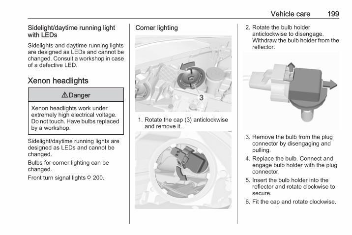
Vehicle care 199
Sidelight/daytime running lightwith LEDsSidelights and daytime running lightsare designed as LEDs and cannot bechanged. Consult a workshop in caseof a defective LED.
Xenon headlights
9 Danger
Xenon headlights work underextremely high electrical voltage.Do not touch. Have bulbs replacedby a workshop.
Sidelight/daytime running lights aredesigned as LEDs and cannot bechanged.Bulbs for corner lighting can bechanged.Front turn signal lights 3 200.
Corner lighting
1. Rotate the cap (3) anticlockwiseand remove it.
2. Rotate the bulb holderanticlockwise to disengage.Withdraw the bulb holder from thereflector.
3. Remove the bulb from the plugconnector by disengaging andpulling.
4. Replace the bulb. Connect andengage bulb holder with the plugconnector.
5. Insert the bulb holder into thereflector and rotate clockwise tosecure.
6. Fit the cap and rotate clockwise.

200 Vehicle care
Fog lightsThe bulbs are accessible from theunderside of the vehicle.
1. Turn the bulb holder anti-clockwise and remove it from thereflector.
2. Disengage the bulb socket fromthe plug connector by pressingthe retaining lug.
3. Remove and replace the bulbsocket with bulb and attach theplug connector.
4. Insert the bulb socket into thereflector by turning clockwise andengage.
Front turn signal lightsFront turn signal lights consist of long-life bulbs which cannot be changed.Consult a workshop in case of adefective long-life bulb.
Tail lights
1. Release the cover in the loadcompartment on the respectiveside and remove.

Vehicle care 201
2. Unscrew both plastic securingnuts from the inside by hand.
3. Carefully withdraw the lightassembly from the recesses andremove.
4. Press the retaining lugs andremove the bulb carrier from thelight assembly.
5. Remove and replace the bulb bypushing the bulb slightly into thesocket and rotating anticlockwise:Tail light/Brake light (1)Turn signal light (2)
6. Insert and turn bulb clockwise intothe tail light assembly. Fit lightassembly with the retaining pinsinto the recesses of the vehiclebody and tighten the plasticsecuring nuts from inside the loadcompartment.Close cover and engage.
Reversing light/rear fog lightReversing light is located on the leftlight assembly in the tailgate, and therear fog light is located on the rightlight assembly in the tailgate.The description of bulb replacementis the same for both lights.
1. Remove screw from the tailgate.

202 Vehicle care
2. Move light assembly slightly to theoutside, then withdraw from thetailgate.
3. Remove the bulb holder byturning.
4. Remove the bulb by pushingslightly into the socket androtating anticlockwise. Replacethe bulb.
5. Insert the bulb socket into theassembly and turn to secure.
6. Attach light assembly into thetailgate and secure with thescrew.
Side turn signal lightsTo replace bulb, remove lamphousing:
1. Slide lamp to its left side andremove with its right end.

Vehicle care 203
2. Turn bulb holder anticlockwiseand remove from housing.
3. Pull bulb from bulb holder andreplace it.
4. Insert bulb holder and turnclockwise.
5. Insert left end of the lamp, slide tothe left and insert right end.
Centre high-mounted brakelightHave LEDs replaced by a workshop.
Number plate light
1. Insert screwdriver in recess of thecover, press to the side andrelease spring.
2. Remove lamp downwards, takingcare not to pull on the cable.
3. Remove bulb holder from lamphousing by turning anticlockwise.

204 Vehicle care
4. Pull bulb from bulb holder andreplace it.
5. Insert bulb holder into lamphousing and turn clockwise.
6. Insert lamp into bumper and letengage.
Interior lightsCourtesy light, reading lightsHave bulbs replaced by a workshop.
Load compartment lightHave bulbs replaced by a workshop.
Dome lightHave bulbs replaced by a workshop.
Instrument panelilluminationHave bulbs replaced by a workshop.
Electrical systemFusesData on the replacement fuse mustmatch the data on the defective fuse.There are two fuse boxes in thevehicle:● in the front left of the engine
compartment● in left-hand drive vehicles, behind
the light switch, or, in right-handdrive vehicles, behind theglovebox
Before replacing a fuse, turn off therespective switch and the ignition.
There are different kinds of fuses inthe vehicle.
Depending on the type of fuse, ablown fuse can be recognized by itsmelted wire. Do not replace the fuseuntil the cause of the fault has beenremedied.Some functions are protected byseveral fuses.Fuses may also be inserted withoutexistence of a function.
Fuse extractorA fuse extractor may be located in thefuse box in the engine compartment.
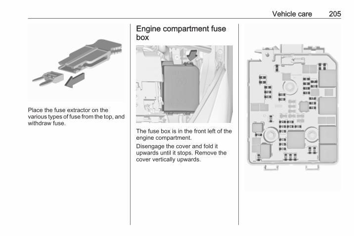
Vehicle care 205
Place the fuse extractor on thevarious types of fuse from the top, andwithdraw fuse.
Engine compartment fusebox
The fuse box is in the front left of theengine compartment.Disengage the cover and fold itupwards until it stops. Remove thecover vertically upwards.
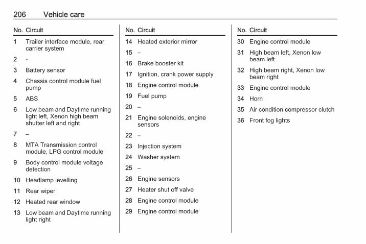
206 Vehicle care
No. Circuit
1 Trailer interface module, rearcarrier system
2 -
3 Battery sensor
4 Chassis control module fuelpump
5 ABS
6 Low beam and Daytime runninglight left, Xenon high beamshutter left and right
7 –
8 MTA Transmission controlmodule, LPG control module
9 Body control module voltagedetection
10 Headlamp levelling
11 Rear wiper
12 Heated rear window
13 Low beam and Daytime runninglight right
No. Circuit
14 Heated exterior mirror
15 –
16 Brake booster kit
17 Ignition, crank power supply
18 Engine control module
19 Fuel pump
20 –
21 Engine solenoids, enginesensors
22 –
23 Injection system
24 Washer system
25 –
26 Engine sensors
27 Heater shut off valve
28 Engine control module
29 Engine control module
No. Circuit
30 Engine control module
31 High beam left, Xenon lowbeam left
32 High beam right, Xenon lowbeam right
33 Engine control module
34 Horn
35 Air condition compressor clutch
36 Front fog lights
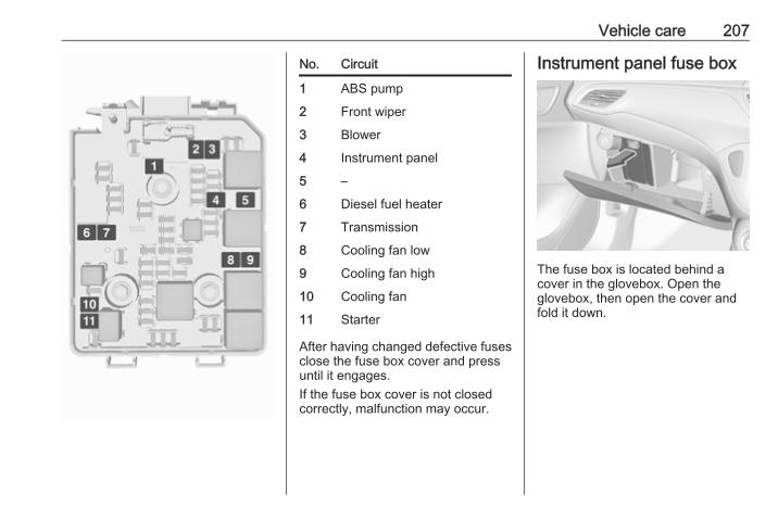
Vehicle care 207
No. Circuit
1 ABS pump
2 Front wiper
3 Blower
4 Instrument panel
5 –
6 Diesel fuel heater
7 Transmission
8 Cooling fan low
9 Cooling fan high
10 Cooling fan
11 Starter
After having changed defective fusesclose the fuse box cover and pressuntil it engages.If the fuse box cover is not closedcorrectly, malfunction may occur.
Instrument panel fuse box
The fuse box is located behind acover in the glovebox. Open theglovebox, then open the cover andfold it down.

208 Vehicle care
No. Circuit
1 –
2 –
3 Power windows
4 Voltage transformer
5 Body control module 1
6 Body control module 2
7 Body control module 3
8 Body control module 4
9 Body control module 5
10 Body control module 6
11 Body control module 7
12 Body control module 8
13 –
14 Tailgate
15 Airbag system
16 Data link connection
17 Ignition
No. Circuit
18 Air conditioning system
19 Sunroof
20 Parking assist/Rain sensor/Front camera
21 Brake switch
22 Audio system
23 Display
24 –
25 Auxiliary jack
26 Instrument panel
27 Seat heating, driver
28 –
29 –
30 Instrument panel/Seat heating/FlexDock
31 Horn
32 Seat heating, passenger
33 Heated steering wheel

Vehicle care 209
No. Circuit
34 –
35 Tyre repair kit
36 –
37 Rear wiper
38 Cigarette lighter
39 Power windows/Sunroof/Auto‐matic transmission display
40 –
Vehicle toolsToolsVehicles with tyre repair kit
The tools are located together withthe towing eye and tyre repair kit inthe load compartment below the floorcover.
On VXR or LPG version or versionswith rear carrier system or doubleload-bay floor, the tools are locatedtogether with the towing eye and tyrerepair kit on the right side of the loadcompartment, behind a cover.

210 Vehicle care
Vehicles with spare wheel
The jack, wheel bolt wrench andsome tools are located on the rightside of the load compartment, behinda cover 3 70.
Wheels and tyres
Tyre condition, wheel conditionDrive over edges slowly and at rightangles if possible. Driving over sharpedges can cause tyre and wheeldamage. Do not trap tyres on the kerbwhen parking.Regularly check the wheels fordamage. Seek the assistance of aworkshop in the event of damage orunusual wear.We recommend not swapping thefront wheels with the rear wheels andvice versa, as this can affect vehiclestability. Always use less worn tyreson the rear axle.
Winter tyresWinter tyres improve driving safety attemperatures below 7 °C and shouldtherefore be fitted on all wheels.All tyre sizes are permitted as wintertyres 3 250.In accordance with country-specificregulations, affix the speed sticker inthe driver's field of view.
Tyre designationsE.g. 195/55 R 16 95 H195 : tyre width, mm55 : cross-section ratio (tyre height
to tyre width), percentageR : belt type: RadialRF : type: RunFlat16 : wheel diameter, inches95 : load index e.g. 95 is equivalent
to 690 kgH : speed code letter
Speed code letter:Q : up to 100 mphS : up to 112 mphT : up to 118 mphH : up to 130 mphV : up to 150 mphW : up to 168 mph
Choose a tyre appropiate for themaximum speed of your verhicle.The maximum speed is achievable atkerb weight with driver (75 kg) plus125 kg payload. Optional equipmentcould reduce the maximum speed ofthe vehicle.Performance 3 244.
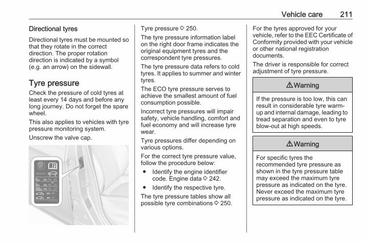
Vehicle care 211
Directional tyresDirectional tyres must be mounted sothat they rotate in the correctdirection. The proper rotationdirection is indicated by a symbol(e.g. an arrow) on the sidewall.
Tyre pressureCheck the pressure of cold tyres atleast every 14 days and before anylong journey. Do not forget the sparewheel.This also applies to vehicles with tyrepressure monitoring system.Unscrew the valve cap.
Tyre pressure 3 250.The tyre pressure information labelon the right door frame indicates theoriginal equipment tyres and thecorrespondent tyre pressures.The tyre pressure data refers to coldtyres. It applies to summer and wintertyres.The ECO tyre pressure serves toachieve the smallest amount of fuelconsumption possible.Incorrect tyre pressures will impairsafety, vehicle handling, comfort andfuel economy and will increase tyrewear.Tyre pressures differ depending onvarious options.For the correct tyre pressure value,follow the procedure below:● Identify the engine identifier
code. Engine data 3 242.● Identify the respective tyre.
The tyre pressure tables show allpossible tyre combinations 3 250.
For the tyres approved for yourvehicle, refer to the EEC Certificate ofConformity provided with your vehicleor other national registrationdocuments.The driver is responsible for correctadjustment of tyre pressure.
9 Warning
If the pressure is too low, this canresult in considerable tyre warm-up and internal damage, leading totread separation and even to tyreblow-out at high speeds.
9 Warning
For specific tyres therecommended tyre pressure asshown in the tyre pressure tablemay exceed the maximum tyrepressure as indicated on the tyre.Never exceed the maximum tyrepressure as indicated on the tyre.

212 Vehicle care
If the tyre pressure must be reducedor increased, switch off ignition. Afteradjusting tyre pressure switch onignition and select the relevant settingon the page Tyre load in the DriverInformation Centre 3 96.
Temperature dependencyThe tyre pressure depends on thetemperature of the tyre. Duringdriving, tyre temperature andpressure increase. Tyre pressurevalues provided on the tyreinformation label and tyre pressurechart are valid for cold tyres, whichmeans at 20 °C.The pressure increases by nearly1.5 psi for a 10 °C temperatureincrease. This must be consideredwhen warm tyres are checked.The tyre pressure value displayed inthe Driver Information Centre showsthe real tyre pressure. A cooled downtyre will show a decreased value,which does not indicate an air leak.
Tyre pressure monitoringsystemThe tyre pressure monitoring systemchecks the pressure of all four tyresonce a minute when vehicle speedexceeds a certain limit.
Caution
Tyre pressure monitoring systemwarns only about low tyre pressurecondition and does not replaceregular tyre maintenance by thedriver.
All wheels must be equipped withpressure sensors and the tyres musthave the prescribed pressure.NoticeIn countries where the tyre pressuremonitoring system is legallyrequired, the use of wheels withoutpressure sensors will invalidate thevehicle type approval.
The current tyre pressures can beshown in the Vehicle InformationMenu ? in the Driver InformationCentre.
The menu can be selected bypressing the buttons on the turnsignal lever.
Press MENU to select the VehicleInformation Menu ?.Turn the adjuster wheel to select thetyre pressure monitoring system.Midlevel display:

Vehicle care 213
The tyre pressure for each tyre isdisplayed on its own page.Uplevel display:
The tyre pressures for all tyres aredisplayed on one page.System status and pressure warningsare displayed by a messageindicating the corresponding tyre inthe Driver Information Centre.The system considers the tyretemperature for the warnings.Temperature dependency 3 211.
A detected low tyre pressurecondition is indicated by the controlindicator w 3 94.If w illuminates, stop as soon aspossible and inflate the tyres asrecommended 3 250.If w flashes for 60-90 seconds thenilluminates continuously, there is afault in the system. Consult aworkshop.
After inflating, some driving may berequired to update the tyre pressurevalues in the Driver InformationCentre. During this time w mayilluminate.If w illuminates at lower temperaturesand extinguishes after driving, thiscould be an indicator for approachinga low tyre pressure condition. Checktyre pressure.Vehicle messages 3 102.If the tyre pressure must be reducedor increased, switch off ignition.Only mount wheels with pressuresensors, otherwise the tyre pressurewill not be displayed and willuminates continuously.A spare wheel or temporary sparewheel is not equipped with pressuresensors. The tyre pressuremonitoring system is not operationalfor these tyres. Control indicator willuminates. For the further threetyres, the system remainsoperational.

214 Vehicle care
The use of commercially-availableliquid tyre repair kits can impair thefunction of the system. Factory-approved repair kits can be used.Operating electronic devices or beingclose to facilities using similar wavefrequencies could disrupt the tyrepressure monitoring system.Each time the tyres are replaced, tyrepressure monitoring system sensorsmust be dismounted and serviced.For the screwed sensor; replacevalve core and sealing ring. For theclipped sensor; replace completevalve stem.
Vehicle loading statusAdjust tyre pressure to load conditionaccording to the tyre information labelor tyre pressure chart 3 250, andselect the appropriate setting in themenu Tyre Load in the DriverInformation Centre, VehicleInformation Menu ? 3 96. Thissetting is the reference for the tyrepressure warnings.
The menu Tyre Load only appears ifthe vehicle is at a standstill and theparking brake is applied. On vehicleswith automatic transmission, theselector lever must be in P.Midlevel display:
Select● LO for comfort pressure up to
three people.● ECO for Eco pressure up to
three people.● Hi for full loading.
Uplevel display:
Select● Light for comfort pressure up to
three people.● Eco for Eco pressure up to
three people.● Max for full loading.
Tyre pressure sensor matchingprocessEach TPMS sensor has a uniqueidentification code. The identificationcode must be matched to a newwheel position after rotating thewheels or exchanging the completewheel set and if one or more tyre

Vehicle care 215
pressure sensors were replaced. Thetyre pressure sensor matchingprocess should also be performedafter replacing a spare wheel with aroad wheel containing a tyre pressuresensor.The malfunction light w and thewarning message or code shouldextinguish at the next ignition cycle.The sensors are matched to thewheel positions, using a relearn tool,in the following order: left side frontwheel, right side front wheel, rightside rear wheel and left side rearwheel. The turn signal light at thecurrent active position is illuminateduntil sensor is matched.Consult a workshop for service orpurchase a relearn tool. There aretwo minutes to match the first wheelposition, and five minutes overall tomatch all four wheel positions. If ittakes longer, the matching processstops and must be restarted.The tyre pressure sensor matchingprocess is:1. Apply the parking brake.2. Turn the ignition on.
3. On vehicles with automatictransmission: set the selectorlever to P.On vehicles with manualtransmission automated: Keepbrake pedal depressed. Move andhold the selector lever for fiveseconds to position N until P isdisplayed in the DriverInformation Centre. P indicatesthat the tyre pressure sensormatching process can be started.On vehicles with manualtransmission: select neutral.
4. Use MENU on the turn signallever to select the VehicleInformation Menu ? in theDriver Information Centre.
5. Turn the adjuster wheel to scroll tothe tyre pressure menu.Midlevel display:
Uplevel display:

216 Vehicle care
6. Press SET/CLR to begin thesensor matching process. Amessage requesting acceptanceof the process should bedisplayed.
7. Press SET/CLR again to confirmthe selection. The horn soundstwice to indicate that the receiveris in relearn mode.
8. Start with the left side front wheel.9. Place the relearn tool against the
tyre sidewall, near the valve stem.Then press the button to activatethe tyre pressure sensor. A hornchirp confirms that the sensoridentification code has beenmatched to this wheel position.
10. Proceed to the right side frontwheel, and repeat the procedurein Step 9.
11. Proceed to the right side rearwheel, and repeat the procedurein Step 9.
12. Proceed to the left side rearwheel, and repeat the procedurein Step 9. The horn sounds twiceto indicate that the sensoridentification code has been
matched to the left side rearwheel, and the tyre pressuresensor matching process is nolonger active.
13. Turn off the ignition.14. Set all four tyres to the
recommended air pressure levelas indicated on the tyre pressureinformation label.
15. Ensure the tyre loading status isset according to the selectedpressure 3 96.
Tread depthCheck tread depth at regularintervals.Tyres should be replaced for safetyreasons at a tread depth of 2-3 mm(4 mm for winter tyres).For safety reasons it is recommendedthat the tread depth of the tyres onone axle should not vary by more than2 mm.
The legally permissible minimumtread depth (1.6 mm) has beenreached when the tread has worndown as far as one of the tread wearindicators (TWI). Their position isindicated by markings on thesidewall.Tyres age, even if they are not used.We recommend tyre replacementevery six years.
Changing tyre and wheelsizeIf tyres of a different size than thosefitted at the factory are used, it may benecessary to reprogramme the

Vehicle care 217
speedometer as well as the nominaltyre pressure and to make othervehicle modifications.After converting to a different tyresize, have the label with tyrepressures replaced.
Caution
When converting to wheels with14 inch diameter, the groundclearance will be reduced. Thismust be considered when passingover obstacles.
9 Warning
Use of unsuitable tyres or wheelsmay lead to accidents and willinvalidate the vehicle typeapproval.
Wheel coversWheel covers and tyres that arefactory approved for the respectivevehicle and comply with all of therelevant wheel and tyre combinationrequirements must be used.
If the wheel covers and tyres used arenot factory approved, the tyres mustnot have a rim protection ridge.Wheel covers must not impair brakecooling.
9 Warning
Use of unsuitable tyres or wheelcovers could lead to suddenpressure loss and therebyaccidents.
Steel wheels: When using lockingwheel nuts don't attach wheel covers.
Tyre chains
Tyre chains are only permitted on thefront wheels.Always use fine mesh chains that addno more than 10 mm to the tyre treadand the inboard sides (including chainlock).
9 Warning
Damage may lead to tyre blowout.
Tyre chains are permitted on tyres ofsize 175/70 R14, 185/70 R14,185/65 R15, 205/45 R17.Tyre chains are permitted on tyres ofsize 195/55 R16 with rims of size16 x 6 and 16 x 6.5, the latter only incombination with limited steeringangle. Seek the assistance of aworkshop.Tyre chains are not permitted on tyresof size 215/45 R17 and 215/40 R18.The use of tyre chains is not permittedon the temporary spare wheel.
Tyre repair kitMinor damage to the tyre tread can berepaired with the tyre repair kit.

218 Vehicle care
Do not remove foreign bodies fromthe tyres.Tyre damage exceeding 4 mm or thatis at the tyre's side wall near the rimcannot be repaired with the tyre repairkit.
9 Warning
Do not drive faster than 50 mph.Do not use for a lengthy period.Steering and handling may beaffected.
If you have a flat tyre:Apply the parking brake and engagefirst gear, reverse gear or P.The tyre repair kit is stowed in the loadcompartment.Depending on the equipment, the tyrerepair kit is in a compartment in theright sidewall or in a compartmentunder the floor cover.
Vehicles with tyre repair kit underthe floor cover
1. Take the tyre repair kit from thecompartment.
2. Remove the compressor.
3. Remove the electrical connectioncable and air hose from thestowage compartments on theunderside of the compressor.

Vehicle care 219
4. Screw the compressor air hose tothe connection on the sealantbottle.
5. Fit the sealant bottle into theretainer on the compressor.Set the compressor near the tyrein such a way that the sealantbottle is upright.
6. Unscrew valve cap from defectivetyre.
7. Screw the filler hose to the tyrevalve.
8. The switch on the compressormust be set to J.
9. Connect the compressor plug tothe power outlet or cigarettelighter socket.To avoid discharging the battery,we recommend running theengine.
10. Set the rocker switch on thecompressor to I. The tyre is filledwith sealant.
11. The compressor pressure gaugebriefly indicates up to six barwhilst the sealant bottle isemptying (approx. 30 seconds).Then the pressure starts to drop.
12. All of the sealant is pumped intothe tyre. Then the tyre is inflated.
13. The prescribed tyre pressureshould be obtained within tenminutes. Tyre pressure 3 250.When the correct pressure isobtained, switch off thecompressor.
If the prescribed tyre pressure isnot obtained within ten minutes,remove the tyre repair kit. Movethe vehicle one tyre rotation.Reattach the tyre repair kit andcontinue the filling procedure forten minutes. If the prescribed tyrepressure is still not obtained, thetyre is too badly damaged. Seekthe assistance of a workshop.

220 Vehicle care
Drain excess tyre pressure withthe button over the pressureindicator.Do not run the compressor forlonger than ten minutes.
14. Detach the tyre repair kit. Pushcatch on bracket to removesealant bottle from bracket. Screwthe tyre inflation hose to the freeconnection of the sealant bottle.This prevents sealant fromescaping. Stow tyre repair kit inload compartment.
15. Remove any excess sealantusing a cloth.
16. Take the label indicatingmaximum permitted speed fromthe sealant bottle and affix in thedriver's field of view.
17. Continue driving immediately sothat sealant is evenly distributedin the tyre. After driving approx.six miles (but no more than tenminutes), stop and check tyrepressure. Screw compressor airhose directly onto tyre valve andcompressor when doing this.
If tyre pressure is more than1.3 bar, set it to the correct value.Repeat the procedure until thereis no more loss of pressure.If the tyre pressure has fallenbelow 1.3 bar, the vehicle mustnot be used. Seek the assistanceof a workshop.
18. Stow away tyre repair kit in loadcompartment.
Vehicles with tyre repair kit in thesidewall
To open the compartment, disengagethe cover and open it.

Vehicle care 221
1. Take the sealant bottle andbracket with air hose from theinsert.
2. Detach air hose from bracket andscrew onto sealant bottleconnection.
3. Position the sealant bottle on thebracket. Make sure that the bottledoes not fall.
4. Unscrew valve cap from defectivetyre.
5. Screw tyre inflation hose to valve.6. Screw air hose onto compressor
connection.7. Switch on ignition.
To avoid discharging the battery,we recommend running theengine.
8. Press on/off switch on thecompressor. The tyre is filled withsealant.
9. The compressor pressure gaugebriefly indicates up to six barwhilst the sealant bottle isemptying (approx. 30 seconds).Then the pressure starts to drop.

222 Vehicle care
10. All of the sealant is pumped intothe tyre. Then the tyre is inflated.
11. The prescribed tyre pressureshould be obtained within tenminutes. Tyre pressure 3 250.When the correct pressure isobtained, switch off thecompressor by pressing the on/offswitch again.If the prescribed tyre pressure isnot obtained within ten minutes,remove the tyre repair kit. Movethe vehicle one tyre rotation.Reattach the tyre repair kit andcontinue the filling procedure forten minutes. If the prescribed tyrepressure is still not obtained, thetyre is too badly damaged. Seekthe assistance of a workshop.Release excess tyre pressureusing ].Do not run the compressor forlonger than ten minutes.
12. Push catch on bracket to removesealant bottle from bracket. Screwthe tyre inflation hose to the freeconnection of the sealant bottle.
This prevents sealant fromescaping. Stow tyre repair kit inload compartment.
13. Remove any excess sealantusing a cloth.
14. Take the label indicatingmaximum permitted speed fromthe sealant bottle and affix in thedriver's field of view.
15. Continue driving immediately sothat sealant is evenly distributedin the tyre. After driving approx.six miles (but no more than tenminutes), stop and check tyrepressure. Screw compressor airhose directly onto tyre valve andcompressor when doing this.If tyre pressure is more than1.3 bar, set it to the correct value.Repeat the procedure until thereis no more loss of pressure.If the tyre pressure has fallenbelow 1.3 bar, the vehicle mustnot be used. Seek the assistanceof a workshop.
16. Stow away tyre repair kit in loadcompartment.
General informationNoticeThe driving characteristics of therepaired tyre are severely affected,therefore have this tyre replaced.If unusual noise is heard or thecompressor becomes hot, turncompressor off for at least30 minutes.The built-in safety valve opens at apressure of seven bar (102 psi).Note the expiry date of the kit. Afterthis date its sealing capability is nolonger guaranteed. Pay attention tostorage information on sealantbottle.Replace the used sealant bottle.Dispose of the bottle as prescribedby applicable laws.The compressor and sealant can beused from approx. -30 °C.The adapters supplied can be usedto pump up other items e.g.footballs, air mattresses, inflatabledinghies etc. They are located on theunderside of the compressor. Toremove, screw on compressor airhose and withdraw adapter.

Vehicle care 223
Wheel changingMake the following preparations andobserve the following information:● Park the vehicle on a level, firm
and non-skid surface. The frontwheels must be in the straight-ahead position.
● Apply the parking brake andengage first gear, reverse gear orP.
● Never change more than onewheel at once.
● Use the jack only to changewheels in case of puncture, notfor seasonal winter or summertyre change.
● The jack is maintenance-free.● If the ground on which the vehicle
is standing is soft, a solid board(max. 1 cm thick) should beplaced under the jack.
● Take heavy objects out of thevehicle before jacking up.
● No people or animals may be inthe vehicle when it is jacked-up.
● Never crawl under a jacked-upvehicle.
● Do not start the vehicle when it israised on the jack.
● Before screwing in the wheelbolts, clean them and lightly coatthe taper of each wheel bolt withcommercially available grease.
9 Warning
Do not grease the thread of thewheel bolt.
1. Steel wheels:Pull off the wheel cover.Alloy wheels with bolt caps:Disengage wheel bolt caps with ascrewdriver and remove. Toprotect the wheel, place a softcloth between the screwdriverand the alloy wheel.
Alloy wheels with centre cap:Insert extractor in the open slot ofthe centre cap and withdraw thecap from the wheel. Vehicle tools3 209.

224 Vehicle care
2. Install the wheel wrench ensuringthat it locates securely and looseneach wheel bolt by half a turn.The wheels might be protected bylocking wheel bolts. To loosenthese specific bolts, first attachthe adapter for the locking wheelbolts onto the head of the boltbefore installing the wheelwrench. The adapter is located inthe glovebox.
3. Ensure the jack is correctlypositioned under the relevantvehicle jacking point.On versions with sill panelling orretrofitted sill panelling, no jack
may be used. The vehicle may bedamaged.
4. Set the jack to the necessaryheight. Position it directly belowthe jacking point in a manner thatprevents it from slipping.
Attach jack handle and with thejack correctly aligned rotatehandle until wheel is clear of theground.
5. Unscrew the wheel bolts.6. Change the wheel.7. Screw on the wheel bolts.8. Lower vehicle.9. Install the wheel wrench ensuring
that it locates securely and tighteneach bolt in a crosswisesequence. Tightening torque is110 Nm.
10. Align the valve hole in the wheelcover of the steel wheel with thetyre valve before installing.

Vehicle care 225
Install wheel bolt caps or centrecap on alloy wheel.
11. Install vehicle jacking point cover.12. Stow and secure the replaced
wheel, the vehicle tools 3 209 andthe adapter for the locking wheelbolts 3 57.
13. Check the tyre pressure of theinstalled tyre and the wheel bolttorque as soon as possible.
Have the defective tyre renewed orrepaired as soon as possible.
Jacking position for lifting platform
Rear arm position of the liftingplatform located centrally under therecess of the sill.
Front arm position of the liftingplatform at the underbody.
Spare wheelIf mounting a spare wheel, which isdifferent from the other wheels, thiswheel might be classified as atemporary spare wheel and thecorresponding speed limits apply,even though no label indicates this.Seek the assistance of a workshop tocheck the applicable speed limit.The spare wheel has a steel rim.
Caution
The use of a spare wheel that issmaller than the other wheels or incombination with winter tyrescould affect driveability. Have thedefective tyre replaced as soon aspossible.
3-door/5-door hatchback
The spare wheel is located in the loadcompartment beneath the floorcovering. It is secured with a wing nut.Fitting a double load-bay floor in thiscase in the upper position 3 70.

226 Vehicle care
To remove, unscrew wing nut, liftspare wheel, move to a verticalposition and remove from above.When stowing the replaced wheel orthe temporary spare wheel back inthe spare wheel well, always securewith the wing nut.Delivery van
Remove load floor.The spare wheel is screwed downtogether with the floor cover.Unscrew wing nut and lift load cover.
Remove spacer above the sparewheel, lift the wheel, move to avertical position and remove fromabove.When stowing the replaced wheel orthe temporary spare wheel back inthe spare wheel well, always insertthe adapter and secure the load coverwith the wing nut.Depending on the defective replacedwheel, the spacer can be omitted ifnecessary, or the wheel can be bolteddown without the floor cover.
Temporary spare wheel
Caution
The use of the temporary sparewheel could affect driveability.Have the defective tyre renewedor repaired as soon as possible.
Only mount one temporary sparewheel. The permissible maximumspeed on the label on the temporaryspare wheel is only valid for thefactory-fitted tyre size.If your vehicle gets a flat tyre on therear while towing another vehicle,mount the temporary spare wheel inthe front and the full size tyre in therear.Tyre chains 3 217.
Spare wheel with directional tyreIf possible, fit directional tyres suchthat they roll in the direction of travel.The rolling direction is indicated by asymbol (e.g. an arrow) on thesidewall.

Vehicle care 227
The following applies to tyres fittedopposing the rolling direction:● Driveability may be affected.
Have the defective tyre renewedor repaired as soon as possibleand fit it instead of the sparewheel.
● Drive particularly carefully on wetand snow-covered roadsurfaces.
Jump startingDo not start with a quick charger.A vehicle with a discharged vehiclebattery can be started using jumpleads and the vehicle battery ofanother vehicle.
9 Warning
Be extremely careful when startingwith jump leads. Any deviationfrom the following instructions canlead to injuries or damage causedby battery explosion or damage tothe electrical systems of bothvehicles.
9 Warning
Avoid contact of the battery witheyes, skin, fabrics and paintedsurfaces. The fluid containssulphuric acid which can causeinjuries and damage in the eventof direct contact.
● Never expose the battery tonaked flames or sparks.
● A discharged vehicle battery canalready freeze at a temperatureof 0 °C. Defrost the frozen batterybefore connecting jump leads.
● Wear eye protection andprotective clothing whenhandling a battery.
● Use a booster battery with thesame voltage (12 Volts). Itscapacity (Ah) must not be muchless than that of the dischargedvehicle battery.
● Use jump leads with insulatedterminals and a cross section ofat least 16 mm2 (25 mm2 fordiesel engines).
● Do not disconnect the dischargedvehicle battery from the vehicle.
● Switch off all unnecessaryelectrical consumers.
● Do not lean over the batteryduring jump starting.
● Do not allow the terminals of onelead to touch those of the otherlead.
● The vehicles must not come intocontact with each other duringthe jump starting process.

228 Vehicle care
● Apply the parking brake,transmission in neutral,automatic transmission in P.
● Open the positive terminalprotection caps of both vehiclebatteries.
Lead connection order:1. Connect the red lead to the
positive terminal of the boostervehicle battery.
2. Connect the other end of the redlead to the positive terminal of thedischarged vehicle battery.
3. Connect the black lead to thenegative terminal of the boostervehicle battery.
4. Connect the other end of the blacklead to a vehicle grounding point,such as the engine block or anengine mounting bolt. Connect asfar away from the dischargedvehicle battery as possible,however at least 60 cm.
Route the leads so that they cannotcatch on rotating parts in the enginecompartment.To start the engine:1. Start the engine of the vehicle
providing the jump.2. After five minutes, start the other
engine. Start attempts should bemade for no longer than15 seconds at an interval of oneminute.
3. Allow both engines to idle forapprox. three minutes with theleads connected.
4. Switch on electrical consumers(e.g. headlights, heated rearwindow) of the vehicle receivingthe jump start.
5. Reverse above sequence exactlywhen removing leads.

Vehicle care 229
TowingTowing the vehicle
Insert a screwdriver in the slot at thelower part of the cap. Release the capby carefully moving the screwdriverdownwards.The towing eye is stowed with thevehicle tools 3 209.
Screw in the towing eye as far as it willgo until it stops in a horizontalposition.Attach a tow rope – or better still a towrod – to the towing eye.The towing eye must only be used fortowing and not for recovering thevehicle.Switch on ignition to release steeringwheel lock and to permit operation ofbrake lights, horn and windscreenwiper.Transmission in neutral.
Caution
Drive slowly. Do not drive jerkily.Excessive tractive force candamage the vehicle.
When the engine is not running,considerably more force is needed tobrake and steer.To prevent the entry of exhaust gasesfrom the towing vehicle, switch on theair recirculation and close thewindows.Vehicles with automatic transmission:the vehicle must be towed facingforwards, not faster than 50 mph norfurther than 60 miles. In all othercases and when the transmission isdefective, the front axle must beraised off the ground.Vehicles with manual transmissionautomated: the vehicle must only betowed facing forwards with the frontaxle raised off the ground.Seek the assistance of a workshop.After towing, unscrew the towing eye.Insert cap at the top and engagedownwards.

230 Vehicle care
Towing another vehicle
Insert a screwdriver in the slot at thelower bend of the cap. Release thecap by carefully moving thescrewdriver downwards.The towing eye is stowed with thevehicle tools 3 209.
Screw in the towing eye as far as it willgo until it stops in a horizontalposition.The lashing eye at the rearunderneath the vehicle must never beused as a towing eye.Attach a tow rope – or even better atow bar – to the towing eye.The towing eye must only be used fortowing and not for recovering avehicle.
Caution
Drive slowly. Do not drive jerkily.Excessive tractive force candamage the vehicle.
After towing, unscrew the towing eye.Insert cap at the top and engagedownwards.

Vehicle care 231
Appearance careExterior careLocksThe locks are lubricated at the factoryusing a high quality lock cylindergrease. Use a de-icing agent onlywhen absolutely necessary, as thishas a degreasing effect and impairslock function. After using a de-icingagent, have the locks regreased by aworkshop.
WashingThe paintwork of your vehicle isexposed to environmental influences.Wash and wax your vehicle regularly.When using automatic vehiclewashes, select a programme thatincludes waxing. Restrictions forfilmed or matt painted body parts ordecor tapes, see "Polishing andwaxing".Bird droppings, dead insects, resin,pollen and the like should be cleanedoff immediately, as they containaggressive constituents which cancause paint damage.
If using a car wash, comply with thecar wash manufacturer's instructions.The windscreen wiper and rearwindow wiper must be switched off.Remove antenna and externalaccessories such as roof racks etc.If you wash your vehicle by hand,make sure that the insides of thewheel housings are also thoroughlyrinsed out.Clean edges and folds on openeddoors and the bonnet as well as theareas they cover.Clean bright metal mouldings with acleaning solution approved foraluminium to avoid damages.
Caution
Always use a cleaning agent witha pH value of four to nine.Do not use cleaning agents on hotsurfaces.
Have the door hinges of all doorsgreased by a workshop.Do not clean the engine compartmentwith a steam-jet or high-pressure jetcleaner.
Thoroughly rinse and leather-off thevehicle. Rinse leather frequently. Useseparate leathers for painted andglass surfaces: remnants of wax onthe windows will impair vision.
Exterior lightsHeadlight and other light covers aremade of plastic. Do not use anyabrasive or caustic agents, do not usean ice scraper, and do not clean themdry.
Polishing and waxingWax painted parts of the vehicleregularly (at the latest when water nolonger beads). Otherwise, thepaintwork will dry out.Polishing is necessary only if the painthas become dull or if solid depositshave become attached to it.Paintwork polish with silicone forms aprotective film, making waxingunnecessary.Unpainted plastic body parts must notbe treated with wax or polishingagents.

232 Vehicle care
Matt filmed body parts or decor tapesmust not be polished, to avoidgleaming. Do not use hot waxprogrammes in automatic car washesif the vehicle is equipped with theseparts.Matt painted decor parts, e.g. mirrorhousing cover, must not be polished.Otherwise these parts would becomeagleam or the colour would bedissolved.
Windows and windscreen wiperbladesUse a soft lint-free cloth or chamoisleather together with window cleanerand insect remover.When cleaning the rear window frominside, always wipe in parallel to theheating element to prevent damage.For mechanical removal of ice, use asharp-edged ice scraper. Press thescraper firmly against the glass sothat no dirt can get under it andscratch the glass.Clean smearing wiper blades with asoft cloth and window cleaner.
Remove dirt residues from smearingwiper blades by using a soft cloth andwindow cleaner. Also make sure toremove any residues such as wax,insect residues and similar from thewindow.Ice residues, pollution and continuouswiping on dry windows will damage oreven destroy the wiper blades.
SunroofNever clean with solvents or abrasiveagents, fuels, aggressive media (e.g.paint cleaner, acetone-containingsolutions etc.), acidic or highlyalkaline media or abrasive pads. Donot apply wax or polishing agents tothe sunroof.
Wheels and tyresDo not use high-pressure jetcleaners.Clean rims with a pH-neutral wheelcleaner.Rims are painted and can be treatedwith the same agents as the body.
Paintwork damageRectify minor paintwork damage witha touch-up pen before rust forms.Have more extensive damage or rustareas repaired by a workshop.
UnderbodySome areas of the vehicle underbodyhave a PVC undercoating while othercritical areas have a durableprotective wax coating.After the underbody is washed, checkthe underbody and have it waxed ifnecessary.Bitumen/rubber materials coulddamage the PVC coating. Haveunderbody work carried out by aworkshop.Before and after winter, wash theunderbody and have the protectivewax coating checked.

Vehicle care 233
Liquid gas system
9 Danger
Liquid gas is heavier than air andcan collect in sink points.Take care when performing workat the underbody in a pit.
For painting work and when using adrying booth at a temperature above60 °C, the liquid gas tank must beremoved.Do not make any modifications to theliquid gas system.
Towing equipmentDo not clean the coupling ball bar witha steam-jet or high-pressure jetcleaner.
Rear carrier systemClean the rear carrier system with asteam-jet or high-pressure jet cleanerat least once a year.Operate the rear carrier systemperiodically if not in regular use, inparticular during winter.
Interior careInterior and upholsteryOnly clean the vehicle interior,including the instrument panel fasciaand panelling, with a dry cloth orinterior cleaner.Clean the leather upholstery withclear water and a soft cloth. In case ofheavy soiling, use leather care.The instrument cluster and thedisplays should only be cleaned usinga soft damp cloth. If necessary use aweak soap solution.Clean fabric upholstery with avacuum cleaner and brush. Removestains with an upholstery cleaner.Clothing fabrics may not becolourfast. This could cause visiblediscolourations, especially on light-coloured upholstery. Removablestains and discolourations should becleaned as soon as possible.Clean seat belts with lukewarm wateror interior cleaner.
Caution
Close Velcro fasteners as openVelcro fasteners on clothing coulddamage seat upholstery.The same applies to clothing withsharp-edged objects, like zips orbelts or studded jeans.
Plastic and rubber partsPlastic and rubber parts can becleaned with the same cleaner asused to clean the body. Use interiorcleaner if necessary. Do not use anyother agent. Avoid solvents and petrolin particular. Do not use high-pressure jet cleaners.

234 Service and maintenance
Service andmaintenance
General information ................... 234Service information .................. 234
Recommended fluids, lubricantsand parts .................................... 235
Recommended fluids andlubricants ................................ 235
General informationService informationIn order to ensure economical andsafe vehicle operation and tomaintain the value of your vehicle, itis of vital importance that allmaintenance work is carried out at theproper intervals as specified.The detailed, up-to-date serviceschedule for your vehicle is availableat the workshop.Service display 3 86.
European service intervalsMaintenance of your vehicle isrequired every 20,000 miles or afterone year, whichever occurs first,unless otherwise indicated in theservice display.A shorter service interval can be validfor severe driving behaviour, e.g. fortaxis and police vehicles.The European service intervals arevalid for the following countries:
Andorra, Austria, Belgium, Bosnia-Herzegovina, Bulgaria, Croatia,Cyprus, Czech Republic, Denmark,Estonia, Finland, France, Germany,Greece, Greenland, Hungary,Iceland, Ireland, Italy, Latvia,Liechtenstein, Lithuania,Luxembourg, Macedonia, Malta,Monaco, Montenegro, Netherlands,Norway, Poland, Portugal, Romania,San Marino, Serbia, Slovakia,Slovenia, Spain, Sweden,Switzerland, United Kingdom.Service display 3 86.
International service intervalsMaintenance of your vehicle isrequired every 10,000 miles or afterone year, whichever occurs first,unless otherwise indicated in theservice display.The international service intervals arevalid for the countries which are notlisted in the European serviceintervals.Service display 3 86.

Service and maintenance 235
ConfirmationsConfirmation of service is recorded inthe Service and Warranty Booklet.The date and mileage is completedwith the stamp and signature of theservicing workshop.Make sure that the Service andWarranty Booklet is completedcorrectly as continuous proof ofservice is essential if any warranty orgoodwill claims are to be met, and isalso a benefit when selling thevehicle.
Service interval with remainingengine oil life durationThe service interval is based onseveral parameters depending onusage.The service display lets you knowwhen to change the engine oil.Service display 3 86.
Recommended fluids,lubricants and partsRecommended fluids andlubricantsOnly use products that meet therecommended specifications.
9 Warning
Operating materials arehazardous and could bepoisonous. Handle with care. Payattention to information given onthe containers.
Engine oilEngine oil is identified by its qualityand its viscosity. Quality is moreimportant than viscosity whenselecting which engine oil to use. Theoil quality ensures e.g. enginecleanliness, wear protection and oilaging control, whereas viscositygrade gives information on the oil'sthickness over a temperature range.
Dexos is the newest engine oil qualitythat provides optimum protection forpetrol and diesel engines. If it isunavailable, engine oils of other listedqualities have to be used.Recommendations for petrol enginesare also valid for Compressed NaturalGas (CNG), Liquified Petroleum Gas(LPG) and Ethanol (E85) fuelledengines.Select the appropriate engine oilbased on its quality and on theminimum ambient temperature3 239.
Topping up engine oilEngine oils of different manufacturersand brands can be mixed as long asthey comply with the required engineoil quality and viscosity.Use of engine oil with onlyACEA A1/B1 or only A5/B5 quality isprohibited, since it can cause long-term engine damage under certainoperating conditions.Select the appropriate engine oilbased on its quality and on theminimum ambient temperature3 239.

236 Service and maintenance
Additional engine oil additivesThe use of additional engine oiladditives could cause damage andinvalidate the warranty.
Engine oil viscosity gradesThe SAE viscosity grade givesinformation of the thickness of the oil.Multigrade oil is indicated by twofigures, e.g. SAE 5W-30. The firstfigure, followed by a W, indicates thelow temperature viscosity and thesecond figure the high temperatureviscosity.Select the appropriate viscosity gradedepending on the minimum ambienttemperature 3 239.All of the recommended viscositygrades are suitable for high ambienttemperatures.
Coolant and antifreezeUse only silicate-free long life coolant(LLC) antifreeze. Consult aworkshop.The system is factory filled withcoolant designed for excellentcorrosion protection and frostprotection down to approx. -28 °C. In
northern countries with very lowtemperatures the factory filled coolantprovides frost protection down toapprox. -37 °C. This concentrationshould be maintained all year round.The use of additional coolantadditives that intend to give additionalcorrosion protection or seal againstminor leaks can cause functionproblems. Liability for consequencesresulting from the use of additionalcoolant additives will be rejected.
Brake and clutch fluidOver time, brake fluid absorbsmoisture which will reduce brakingeffectiveness. The brake fluid shouldtherefore be replaced at the specifiedinterval.

Technical data 237
Technical data
Vehicle identification .................. 237Vehicle Identification Number .. 237Identification plate ................... 238Engine identification ................ 238
Vehicle data ............................... 239Recommended fluids andlubricants ................................ 239
Engine data ............................. 242Performance ............................ 244Vehicle weight ......................... 246Vehicle dimensions ................. 248Capacities ................................ 249Tyre pressures ........................ 250
Vehicle identificationVehicle IdentificationNumber
The Vehicle Identification Number isstamped on the identification plateand on the floor pan, under the floorcovering, visible under a cover.
The Vehicle Identification Numbermay be embossed on the instrumentpanel, visible through the windscreen,or in the engine compartment on theright body panel.

238 Technical data
Identification plate
The identification plate is located onthe left or right door frame.
Information on identification label:1 : manufacturer2 : type approval number3 : vehicle identification number4 : permissible gross vehicle weight
rating in kg5 : permissible gross train weight
in kg6 : maximum permissible front axle
load in kg7 : maximum permissible rear axle
load in kg8 : vehicle-specific or country-
specific data
The combined total of front and rearaxle loads must not exceed thepermissible gross vehicle weight. Forexample, if the front axle is bearing itsmaximum permissible load, the rearaxle can only bear a load that is equalto the gross vehicle weight minus thefront axle load.The technical data is determined inaccordance with EuropeanCommunity standards. We reservethe right to make modifications.Specifications in the vehicledocuments always have priority overthose given in this manual.
Engine identificationThe technical data tables use theengine identifier code. The enginedata table additionally shows theengineering code. Engine data3 242.To identify the respective engine,refer to the EEC Certificate ofConformity provided with your vehicleor other national registrationdocuments.The Certificate of Conformity showsthe engine identifier code, othernational publications may show theengineering code. Check pistondisplacement and engine power toidentify the respective engine.
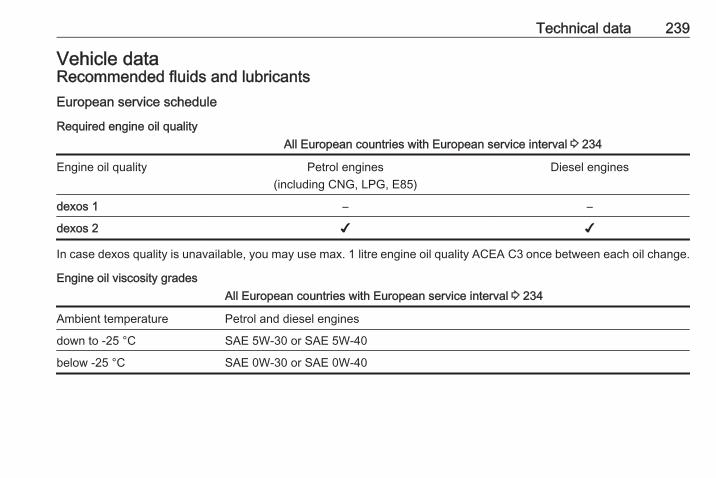
Technical data 239
Vehicle dataRecommended fluids and lubricantsEuropean service schedule
Required engine oil qualityAll European countries with European service interval 3 234
Engine oil quality Petrol engines(including CNG, LPG, E85)
Diesel engines
dexos 1 – –
dexos 2 ✔ ✔
In case dexos quality is unavailable, you may use max. 1 litre engine oil quality ACEA C3 once between each oil change.
Engine oil viscosity gradesAll European countries with European service interval 3 234
Ambient temperature Petrol and diesel engines
down to -25 °C SAE 5W-30 or SAE 5W-40
below -25 °C SAE 0W-30 or SAE 0W-40

240 Technical data
International service schedule
Required engine oil qualityAll countries with international service interval 3 234
Engine oil quality Petrol engines(including CNG, LPG, E85)
Diesel engines
dexos 1 (if available) ✔ –
dexos 2 ✔ ✔
In case dexos quality is unavailable, you may use the oil qualities listed below:
All countries with international service interval 3 234
Engine oil quality Petrol engines(including CNG, LPG, E85)
Diesel engines
GM-LL-A-025 ✔ –
GM-LL-B-025 – ✔
All countries with international service interval 3 234
Engine oil quality Petrol engines(including CNG, LPG, E85)
Diesel engines
ACEA A3/B3 ✔ –
ACEA A3/B4 ✔ ✔

Technical data 241
All countries with international service interval 3 234
ACEA C3 ✔ ✔
API SM ✔ –
API SN resource conserving ✔ –
Engine oil viscosity gradesAll countries with international service interval 3 234
Ambient temperature Petrol and diesel engines
down to -25 °C SAE 5W-30 or SAE 5W-40
below -25 °C SAE 0W-30 or SAE 0W-40
down to -20 °C SAE 10W-301) or SAE 10W-40
1) Permitted, but usage of SAE 5W-30 or SAE 5W-40 with dexos quality is recommended.
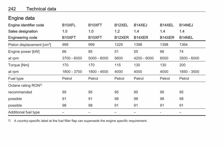
242 Technical data
Engine dataEngine identifier code B10XFL B10XFT B12XEL B14XEJ B14XEL B14NEJSales designation 1.0 1.0 1.2 1.4 1.4 1.4Engineering code B10XFT B10XFT B12XER B14XER B14XER B14NEL
Piston displacement [cm3] 999 999 1229 1398 1398 1364
Engine power [kW] 66 85 51 55 66 74
at rpm 3700 - 6000 5000 - 6000 5600 4200 - 6000 6000 3500 - 6000
Torque [Nm] 170 170 115 130 130 200
at rpm 1800 - 3700 1800 - 4500 4000 4000 4000 1850 - 3500
Fuel type Petrol Petrol Petrol Petrol Petrol Petrol
Octane rating RON2)
recommended 95 95 95 95 95 95
possible 91 91 98 98 98 98
possible 98 98 91 91 91 91
Additional fuel type – – – – - –
2) A country-specific label at the fuel filler flap can supersede the engine specific requirement.

Technical data 243
Engine identifier code B14XEL B14NEH B16LERSales designation 1.4 LPG 1.4 Turbo VXREngineering code B14XER B14NET B16LER
Piston displacement [cm3] 1398 1364 1598
Engine power [kW] 66 110 152
at rpm 6000 5000 5800
Torque [Nm] 1303) 220 245
at rpm 4000 3000-4500 1900-5800
Fuel type Liquid gas/Petrol Petrol Petrol
Octane rating RON2)
recommended 95 98 100
possible 98 95 98
possible 91 – –
Additional fuel type Liquid gas (LPG) – –
2) A country-specific label at the fuel filler flap can supersede the engine specific requirement.3) LPG operation: 124.

244 Technical data
Engine identifier code B13DTC B13DTE B13DTE B13DTRSales designation 1.3 1.3 1.3 1.3Engineering code B13DTC B13DTE B13DTE B13DTR
Piston displacement [cm3] 1248 1248 1248 1248
Engine power [kW] 55 55 70 70
at rpm 3750 3750 3750 3750
Torque [Nm] 190 190 190 210
at rpm 1500 - 2500 1500 - 2500 1500 - 3500 1500 - 3000
Fuel type Diesel Diesel Diesel Diesel
Additional fuel type – – – –
PerformanceEngine B10XFL B10XFT B12XEL B14XEJ B14XEL B14NEJ
Maximum speed [mph]
Manual transmission 112 122 101 104 109 115
Manual transmission automated – – – – 109 –
Automatic transmission – – – – 106 –

Technical data 245
Engine B14XEL LPG B14NEH B16LER
Maximum speed [mph]
Manual transmission 109 129 143
Manual transmission automated – – –
Automatic transmission – – –
EngineB13DTC B13DTE
55kWB13DTE70kW
B13DTR
Maximum speed [mph]
Manual transmission 102 102 113 110
Manual transmission automated – – 113 –
Automatic transmission – – – –

246 Technical data
Vehicle weightKerb weight, 5-door vehicle, basic model without any optional equipment
Engine Manual transmission Manual transmissionautomated
Automatic transmission
without / with air conditioning[kg]
B10XFL 1199 / 1214 – –
B10XFT 1199 / 1214 – –
B12XEL 1163 / 1178 – –
B14XEJ 1163 / 1178 – –
B14XEL 1163 / 1178 1163 / 1178 1199 / 1214
B14XEL LPG 1237 / 1252 – –
B14NEJ 1237 / 1252 – –
B14NEH 1259 / 1274 – –
without / with air conditioning[kg]
B13DTC 1237 / 1252 – –
B13DTE 1237 / 1331 1237 / 1331 –
B13DTR 1259 / 1274 – –
Optional equipment and accessories increase the kerb weight.Loading information 3 73.

Technical data 247
Kerb weight, 3-door vehicle and van, basic model without any optional equipment
Engine Manual transmission Manual transmissionautomated
Automatic transmission
without / with air conditioning[kg]
B10XFL 1163 / 1178 – –
B10XFT 1163 / 1178 – –
B12XEL 1120 / 1135 – –
B14XEJ 1141 / 1156 – –
B14XEL 1141 / 1156 1141 / 1156 1163 / 1178
B14XEL LPG 1199 / 1214 – –
B14NEJ 1199 / 1214 – –
B14NEH 1199 / 1214 – –
B16LER 1278 / 1293 – –
without/with air conditioning[kg]
B13DTC 1199 / 1214 – –
B13DTE 1199 / 1214 1199 / 1214 –
B13DTR 1237 / 1252 – –
Optional equipment and accessories increase the kerb weight.Loading information 3 73.

248 Technical data
Vehicle dimensions5-door vehicle 3-door vehicle VXR
Length [mm] 4021 4036 4036
Width without exterior mirrors [mm] 1746 1736 1736
Width with two exterior mirrors [mm] 1944 1944 1944
Height (without antenna) [mm]4) 1466 - 1516 1466 - 1501 1466 - 1501
Length of load compartment floor [mm] 705 705 705
Length of load compartment with folded rear seats [mm] 1372 1372 1372
Load compartment width [mm] 944 944 944
Load compartment height with cover [mm] 542 542 542
Load compartment height without cover [mm] 876 843 843
Wheelbase [mm] 2510 2510 2510
Turning circle diameter [m]5) 11.0 - 11.9 11.0 - 11.9 11.0 - 11.9
4) Depending on options.5) Depending on body- and equipment variants.
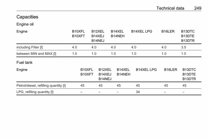
Technical data 249
CapacitiesEngine oil
Engine B10XFLB10XFT
B12XELB14XEJB14NEJ
B14XELB14NEH
B14XEL LPG B16LER B13DTCB13DTEB13DTR
including Filter [l] 4.0 4.0 4.0 4.0 4.0 3.5
between MIN and MAX [l] 1.0 1.0 1.0 1.0 1.0 1.0
Fuel tank
Engine B10XFLB10XFT
B12XELB14XEJB14NEJ
B14XELB14NEH
B14XEL LPG B16LER B13DTCB13DTEB13DTR
Petrol/diesel, refilling quantity [l] 45 45 45 45 45 45
LPG, refilling quantity [l] – – – 34 – –

250 Technical data
Tyre pressuresComfort with up to 3 people ECO with up to 3 people With full load
Engine Tyres front rear front rear front rear[kPa/bar]([psi])
[kPa/bar]([psi])
[kPa/bar]([psi])
[kPa/bar]([psi])
[kPa/bar]([psi])
[kPa/bar]([psi])
B12XEL,B14XEL,B14XEL LPG,B14XEJ
175/70 R14,185/70 R14,185/65 R15,195/55 R16,215/45 R17
210/2.1 (31) 210/2.1 (31) 270/2.7 (39) 250/2.5 (37) 260/2.6 (38) 320/3.2 (46)
B10XFL,B10XFT,B14NEJ
185/65 R15,195/55 R16,215/45 R17
230/2.3 (34) 230/2.3 (34) 270/2.7 (39) 250/2.5 (37) 260/2.6 (38) 320/3.2 (46)
B10XFT SPORT 195/55 R16 230/2.3 (34) 230/2.3 (34) 270/2.7 (39) 250/2.5 (37) 260/2.6 (38) 320/3.2 (46)
215/45 R17 240/2.4 (35) 240/2.4 (35) 270/2.7 (39) 250/2.5 (37) 260/2.6 (38) 320/3.2 (46)
B13DTC,B13DTE,B13DTR
185/65 R15,195/55 R16,215/45 R17
230/2.3 (34) 230/2.3 (34) 270/2.7 (39) 250/2.5 (37) 260/2.6 (38) 320/3.2 (46)
B14NEH 195/55 R16,215/45 R17
230/2.3 (34) 230/2.3 (34) 270/2.7 (39) 250/2.5 (37) 260/2.6 (38) 320/3.2 (46)

Technical data 251
Comfort with up to 3 people ECO with up to 3 people With full loadEngine Tyres front rear front rear front rear
[kPa/bar]([psi])
[kPa/bar]([psi])
[kPa/bar]([psi])
[kPa/bar]([psi])
[kPa/bar]([psi])
[kPa/bar]([psi])
B14NEH SPORT 195/55 R16 230/2.3 (34) 230/2.3 (34) 270/2.7 (39) 250/2.5 (37) 260/2.6 (38) 320/3.2 (46)
215/45 R17 240/2.4 (35) 240/2.4 (35) 270/2.7 (39) 250/2.5 (37) 260/2.6 (38) 320/3.2 (46)
B16LER 205/45 R17,215/45 R17
240/2.4 (35) 240/2.4 (35) 270/2.7 (39) 250/2.5 (37) 260/2.6 (38) 320/3.2 (46)
215/40 R18 240/2.4 (35) 240/2.4 (35) 270/2.7 (39) 250/2.5 (37) 280/2.8 (41) 320/3.2 (46)

252 Customer information
Customerinformation
Customer information ................ 252Declaration of conformity ......... 252Collision damage repair ........... 254Software acknowledgement .... 254
Vehicle data recording and pri‐vacy ........................................... 256
Event data recorders ............... 256Radio Frequency Identification(RFID) ..................................... 257
Customer informationDeclaration of conformityTransmission systemsThis vehicle has systems thattransmit and/or receive radio wavessubject to Directive 1999/5/EC.These systems are in compliancewith the essential requirements andother relevant provisions of Directive1999/5/EC. Copies of the originalDeclarations of Conformity can beobtained on our website.

Customer information 253
Jack
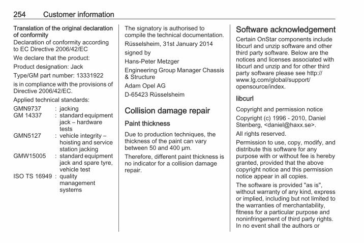
254 Customer information
Translation of the original declarationof conformityDeclaration of conformity accordingto EC Directive 2006/42/ECWe declare that the product:Product designation: JackType/GM part number: 13331922is in compliance with the provisions ofDirective 2006/42/EC.Applied technical standards:GMN9737 : jackingGM 14337 : standard equipment
jack – hardwaretests
GMN5127 : vehicle integrity –hoisting and servicestation jacking
GMW15005 : standard equipmentjack and spare tyre,vehicle test
ISO TS 16949 : qualitymanagementsystems
The signatory is authorised tocompile the technical documentation.Rüsselsheim, 31st January 2014signed byHans-Peter MetzgerEngineering Group Manager Chassis& StructureAdam Opel AGD-65423 Rüsselsheim
Collision damage repairPaint thicknessDue to production techniques, thethickness of the paint can varybetween 50 and 400 µm.Therefore, different paint thickness isno indicator for a collision damagerepair.
Software acknowledgementCertain OnStar components includelibcurl and unzip software and otherthird party software. Below are thenotices and licenses associated withlibcurl and unzip and for other thirdparty software please see http://www.lg.com/global/support/opensource/index.
libcurlCopyright and permission noticeCopyright (c) 1996 - 2010, DanielStenberg, <[email protected]>.All rights reserved.Permission to use, copy, modify, anddistribute this software for anypurpose with or without fee is herebygranted, provided that the abovecopyright notice and this permissionnotice appear in all copies.The software is provided "as is",without warranty of any kind, expressor implied, including but not limited tothe warranties of merchantability,fitness for a particular purpose andnoninfringement of third party rights.In no event shall the authors or

Customer information 255
copyright holders be liable for anyclaim, damages or other liability,whether in an action of contract, tortor otherwise, arising from, out of or inconnection with the software or theuse or other dealings in the software.Except as contained in this notice, thename of a copyright holder shall notbe used in advertising or otherwise topromote the sale, use or otherdealings in this Software without priorwritten authorization of the copyrightholder.
unzipThis is version 2005-Feb-10 of theInfo-ZIP copyright and license. Thedefinitive version of this documentshould be available at ftp://ftp.info-zip.org/pub/infozip/license.htmlindefinitely.Copyright (c) 1990-2005 Info-ZIP. Allrights reserved.For the purposes of this copyright andlicense, “Info-ZIP” is defined as thefollowing set of individuals:Mark Adler, John Bush, Karl Davis,Harald Denker, Jean-Michel Dubois,Jean-loup Gailly, Hunter Goatley, Ed
Gordon, Ian Gorman, Chris Herborth,Dirk Haase, Greg Hartwig, RobertHeath, Jonathan Hudson, PaulKienitz, David Kirschbaum, JohnnyLee, Onno van der Linden, IgorMandrichenko, Steve P. Miller, SergioMonesi, Keith Owens, GeorgePetrov, Greg Roelofs, Kai UweRommel, Steve Salisbury, DaveSmith, Steven M. Schweda, ChristianSpieler, Cosmin Truta, AntoineVerheijen, Paul von Behren, RichWales, Mike White.This software is provided “as is,”without warranty of any kind, expressor implied. In no event shall Info-ZIPor its contributors be held liable forany direct, indirect, incidental, specialor consequential damages arising outof the use of or inability to use thissoftware.Permission is granted to anyone touse this software for any purpose,including commercial applications,and to alter it and redistribute it freely,subject to the following restrictions:
1. Redistributions of source codemust retain the above copyrightnotice, definition, disclaimer, andthis list of conditions.
2. Redistributions in binary form(compiled executables) mustreproduce the above copyrightnotice, definition, disclaimer, andthis list of conditions indocumentation and/or othermaterials provided with thedistribution. The sole exception tothis condition is redistribution of astandard UnZipSFX binary(including SFXWiz) as part of aself-extracting archive; that ispermitted without inclusion of thislicense, as long as the normalSFX banner has not beenremoved from the binary ordisabled.
3. Altered versions--including, butnot limited to, ports to newoperating systems, existing portswith new graphical interfaces, anddynamic, shared, or static libraryversions--must be plainly markedas such and must not bemisrepresented as being the

256 Customer information
original source. Such alteredversions also must not bemisrepresented as being Info-ZIPreleases--including, but notlimited to, labeling of the alteredversions with the names “Info-ZIP” (or any variation thereof,including, but not limited to,different capitalizations), “PocketUnZip,” “WiZ” or “MacZip” withoutthe explicit permission of Info-ZIP.Such altered versions are furtherprohibited from misrepresentativeuse of the Zip-Bugs or Info-ZIP e-mail addresses or of the Info-ZIPURL(s).
4. Info-ZIP retains the right to usethe names “Info-ZIP,” “Zip,”“UnZip,” “UnZipSFX,” “WiZ,”“Pocket UnZip,” “Pocket Zip,” and“MacZip” for its own source andbinary releases.
Vehicle data recordingand privacyEvent data recordersData storage modules in thevehicleA large number of electroniccomponents of your vehicle containdata storage modules temporarily orpermanently storing technical dataabout the condition of the vehicle,events and errors. In general, thistechnical information documents thecondition of parts, modules, systemsor the environment:● Operating conditions of system
components (e.g. filling levels).● Status messages of the vehicle
and its single components (e.g.number of wheel revolutions /rotational speed, deceleration,lateral acceleration).
● Dysfunctions and defects inimportant system components.
● Vehicle reactions in particulardriving situations (e.g. inflation ofan airbag, activation of thestability regulation system).
● Environmental conditions (e.g.temperature).
These data are exclusively technicaland help identifying and correctingerrors as well as optimizing vehiclefunctions.Motion profiles indicating travelledroutes cannot be created with thesedata.If services are used (e.g. repairworks, service processes, warrantycases, quality assurance),employees of the service network(manufacturer included) are able toread out this technical informationfrom the event and error data storagemodules applying special diagnosticdevices. If required, you will receivefurther information at theseworkshops. After an error has beencorrected, the data are deleted fromthe error storage module or they areconstantly overwritten.

Customer information 257
When using the vehicle, situationsmay occur in which these technicaldata related to other information(accident report, damages on thevehicle, witness statements etc.) maybe associated with a specific person -possibly, with the assistance of anexpert.Additional functions contractuallyagreed upon with the client (e.g.vehicle location in emergency cases)allow the transmission of particularvehicle data from the vehicle.
Radio FrequencyIdentification (RFID)RFID technology is used in somevehicles for functions such as tyrepressure monitoring and ignitionsystem security. It is also used inconnection with conveniences suchas radio remote controls for doorlocking/unlocking and starting, and in-vehicle transmitters for garage dooropeners. RFID technology inVauxhall vehicles does not use orrecord personal information or linkwith any other Vauxhall systemcontaining personal information.

258
Index AAccessories and vehicle
modifications .......................... 188Adjustable air vents ................... 130Airbag and belt tensioners ........... 90Airbag deactivation ................ 48, 91Airbag label................................... 43Airbag system .............................. 43Air conditioning regular
operation ................................ 131Air conditioning system .............. 123Air intake .................................... 130Air vents...................................... 130Antilock brake system ................ 148Antilock brake system (ABS) ....... 92Anti-theft alarm system ................ 27Anti-theft locking system .............. 26Appearance care........................ 231Ashtrays ....................................... 83Automatic anti-dazzle .................. 30Automatic light control ............... 113Automatic locking ........................ 24Automatic transmission ............. 140Autostop............................... 95, 135
BBattery discharge protection ...... 121Battery voltage ........................... 104Belts.............................................. 40Bicycle rack.................................. 59
Bonnet ....................................... 189Brake and clutch fluid................. 235Brake and clutch system ............. 92Brake assist ............................... 149Brake fluid .................................. 193Brakes ............................... 148, 193Breakdown.................................. 229Bulb replacement ....................... 196
CCapacities .................................. 249Car Pass ...................................... 21Catalytic converter ..................... 140Central locking system ................ 22Centre high-mounted brake light 203Changing tyre and wheel size . . . 216Charging system .......................... 91Child locks ................................... 25Child restraint installation
locations ................................... 51Child restraints.............................. 49Child restraint systems ................ 49Cigarette lighter ........................... 82City mode................................... 152Climate control ............................. 15Climate control systems............. 122Clock ............................................ 80Code........................................... 102Collision damage repair.............. 254Colour-Info-Display..................... 100
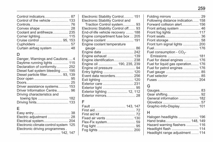
259
Control indicators.......................... 87Control of the vehicle ................. 133Controls........................................ 76Convex shape .............................. 28Coolant and antifreeze............... 235Corner lighting............................ 115Cruise control ...................... 95, 153Cupholders .................................. 57Curtain airbag system .................. 48
DDanger, Warnings and Cautions . . . 4Daytime running lights ............... 115Declaration of conformity............ 252Diesel fuel system bleeding ....... 195Diesel particle filter............... 93, 139Door open .................................... 95Doors............................................ 25Driver assistance systems.......... 153Driver Information Centre............. 96Driving characteristics and
towing tips .............................. 182Driving hints................................ 133
EEasy entry..................................... 38Electric adjustment ...................... 28Electrical system......................... 204Electronic climate control system 125Electronic driving programmes .
........................................ 142, 147
Electronic Stability Control.......... 151Electronic Stability Control and
Traction Control system............ 93Electronic Stability Control off....... 93End-of-life vehicle recovery ....... 188Engine compartment fuse box ... 205Engine coolant ........................... 191Engine coolant temperature
gauge ....................................... 86Engine data ............................... 242Engine exhaust .......................... 139Engine identification................... 238Engine oil ................... 190, 235, 239Engine oil pressure ...................... 94Entry lighting .............................. 120Event data recorders.................. 256Exit lighting ................................ 120Exterior care .............................. 231Exterior light ................................. 95Exterior lighting .................... 12, 112Exterior mirrors............................. 28
FFault ................................... 143, 147First aid......................................... 72First aid kit ................................... 72Fixed air vents ........................... 130Flex-Fix system............................ 59Fog light ....................................... 95Fog lights ................................... 200
Folding mirrors ............................. 29Following distance indication...... 158Forward collision alert................. 156Front airbag system ..................... 46Front fog lights ........................... 117Front seats.................................... 36Front storage................................ 58Front turn signal lights ............... 200Fuel............................................. 176Fuel consumption - CO2-
Emissions ............................... 181Fuel for diesel engines .............. 176Fuel for liquid gas operation....... 176Fuel for petrol engines ............... 176Fuel gauge ................................... 85Fuel selector ................................ 85Fuses ......................................... 204
GGauges......................................... 83Gear shifting................................. 92General information ................... 182Glovebox ..................................... 57Graphic-Info-Display................... 101
HHalogen headlights .................... 196Hand brake......................... 148, 149Hazard warning flashers ............ 116Headlight flash ........................... 114Headlight range adjustment ...... 114

260
Headlights................................... 112Headlights when driving abroad 114Head restraint adjustment ............. 8Head restraints ............................ 35Heated mirrors ............................. 29Heated rear window ..................... 32Heated steering wheel ................. 76Heated windscreen....................... 32Heating ........................................ 39Heating and ventilation system . 122High beam ........................... 95, 114High beam assist.................. 95, 115Hill start assist ........................... 149Horn ....................................... 13, 77
IIdentification plate ..................... 238Ignition switch positions ............. 133Immobiliser ............................ 28, 94Indicators...................................... 83Information displays...................... 96Instrument cluster ........................ 83Instrument panel fuse box ......... 207Instrument panel illumination ..... 204Instrument panel illumination
control .................................... 118Instrument panel overview ........... 10Interior care ............................... 233Interior lighting............................ 118Interior lights ...................... 119, 204
Interior mirrors.............................. 29Interruption of power supply ...... 143Introduction .................................... 3ISOFIX child restraint systems .... 55
JJump starting ............................. 227
KKey, memorised settings.............. 22Keys ............................................. 20Keys, locks................................... 20
LLane departure warning....... 92, 175Lashing eyes ............................... 71Light switch ................................ 112Load compartment ................ 25, 67Load compartment cover ............. 69Loading information ..................... 73Low fuel ....................................... 94
MMalfunction indicator light ............ 91Manual anti-dazzle ...................... 29Manual mode ..................... 142, 147Manual transmission .................. 144Manual transmission automated 144Manual windows .......................... 30Memorised settings...................... 22
Mirror adjustment ........................... 8Misted light covers ..................... 118
NNew vehicle running-in .............. 133Number plate light ..................... 203
OObject detection systems........... 159Odometer ..................................... 83Oil, engine.......................... 235, 239OnStar........................................ 108Operate pedal............................... 92Outside temperature .................... 79Overrun cut-off ........................... 135
PParking ................................ 18, 138Parking assist ............................ 159Parking brake ............................ 149Parking lights ............................. 118Particulate filter........................... 139Performance .............................. 244Performing work ........................ 189Pollen filter ................................. 130Power outlets ............................... 82Power steering.............................. 92Power windows ............................ 30Preheating ................................... 93Puncture..................................... 223
261
RRadio Frequency Identification
(RFID)..................................... 257Radio remote control ................... 21Reading lights ............................ 120Rear carrier system...................... 59Rear floor storage cover .............. 70Rear fog light ....................... 95, 117Rear view camera ...................... 170Rear window wiper/washer .......... 79Recommended fluids and
lubricants ........................ 235, 239Reduced engine power................ 94Refuelling ................................... 178Retained power off..................... 134Reversing lights ......................... 118Ride control systems.................. 150Roof.............................................. 33Roof load...................................... 73Roof rack ..................................... 72
SSafety belts................................... 40Seat adjustment ....................... 7, 37Seat belt ........................................ 8Seat belt reminder ....................... 90Seat belts ..................................... 40Seat folding .................................. 38Seat heating................................. 39Seat position ................................ 36
Selector lever ..................... 141, 145Service ....................................... 131Service display ............................ 86Service information .................... 234Service vehicle soon .................... 91Side airbag system ...................... 47Side blind spot alert.................... 169Sidelights.................................... 112Side turn signal lights ................ 202Software acknowledgement....... 254Spare wheel ............................... 225Speed limiter......................... 95, 155Speedometer ............................... 83Starting and operating................ 133Starting off ................................... 17Starting the engine ............ 134, 145Steering wheel adjustment ...... 9, 76Steering wheel controls ............... 76Stop-start system........................ 135Storage......................................... 57Storage compartments................. 57Sunroof ........................................ 33Sun visors .................................... 32Symbols ......................................... 4
TTachometer ................................. 84Tail lights ................................... 200Three-point seat belt .................... 41Tools .......................................... 209
Top-tether fastening eyes ............ 55Tow bar....................................... 182Towing................................ 182, 229Towing another vehicle ............. 230Towing equipment ..................... 184Towing the vehicle ..................... 229Traction Control system ............. 150Traction Control system off........... 93Traffic sign assistant............. 95, 171Trailer coupling........................... 182Trailer stability assist ................. 186Trailer towing ............................. 183Transmission ............................... 16Transmission display ......... 140, 145Tread depth ............................... 216Trip odometer .............................. 83Turn and lane-change signals ... 117Turn signal ................................... 89Tyre chains ................................ 217Tyre designations ...................... 210Tyre pressure ............................ 211Tyre pressure monitoring
system............................... 94, 212Tyre pressures ........................... 250Tyre repair kit ............................. 217
UUltrasonic parking assist ...... 93, 159Underseat storage ....................... 59

262
Upholstery.................................. 233Using this manual .......................... 3
VVehicle battery ........................... 193Vehicle checks............................ 189Vehicle data................................ 239Vehicle data recording and
privacy..................................... 256Vehicle detected ahead................ 95Vehicle dimensions .................... 248Vehicle Identification Number .... 237Vehicle jack................................ 209Vehicle messages ..................... 102Vehicle personalisation ............. 105Vehicle security............................ 26Vehicle specific data ...................... 3Vehicle storage........................... 188Vehicle tools............................... 209Vehicle unlocking ........................... 6Vehicle weight ........................... 246Ventilation................................... 122
WWarning chimes ......................... 104Warning lights............................... 83Warning triangle .......................... 72Washer and wiper systems ......... 14Washer fluid ............................... 193Wheel changing ......................... 223Wheel covers ............................. 217
Wheels and tyres ....................... 210Windows....................................... 30Windscreen................................... 30Windscreen wiper/washer ........... 77Winter tyres ............................... 210Wiper blade replacement .......... 195
XXenon headlights ....................... 199Xenon lighting system................ 115

Copyright by General Motors UK Ltd.
The information contained in this publication is effective as of the date indicated below. General Motors UK Ltd. reserves the rightto make changes to the technical specifications, features and design of the vehicles relative to the information contained in thispublication, as well as changes to the publication itself.
Edition: January 2016, General Motors UK Ltd.
Printed on chlorine-free bleached paper.
*KTA-2764/4-VX-EN*
KTA-2764/4-VX-en 01/2016