Vario PRO - Amazon Web Services PRO...Vario PRO is compatible with our complete range of...
24
Vario PRO Installation Guide YOUR STEP-BY-STEP GUIDE TO THE PERFECT INSTALLATION PLEASE ENSURE YOU HAVE READ AND FULLY UNDERSTOOD THIS GUIDE BEFORE INSTALLATION! ! the ORIGINAL!
Transcript of Vario PRO - Amazon Web Services PRO...Vario PRO is compatible with our complete range of...

Vario PROInstallation GuideYOUR STEP-BY-STEP GUIDE TO THE PERFECT INSTALLATION
PLEASE ENSURE YOU HAVE READ AND FULLY UNDERSTOOD THIS GUIDE BEFORE INSTALLATION!!
the ORIGINAL!

WWW. WWW. WWW. WWW. WWW.
Questions? Call our technical team on 0800 019 5899
Thank you for your purchase...
Thank you for choosing a Thermogroup UK product. Our commitment to simple, honest, on-time quality service ensures that we are here to help throughout every stage of your project from idea to installation and, most importantly, after sales support.
This document will provide a step-by-step guide to a perfect installation as well as details on your warranty and how to get technical support should you need it.
Warranty, Terms and Conditions* A message from customer care...
The Thermogroup UK Lifetime Warranty guarantees Vario PRO underfloor heating kits to remain free from defects in workmanship and materials under normal use and maintenance, and is guaranteed to remain in full working order subject to the conditions and limitations below:
Please complete the customer handover section on p20 in full so the customer has all the information they require to complete the online warranty form. This is required to validate the Lifetime warranty.
Proof of purchase must be presented to make a claim, so please ensure that you keep a copy of both your invoice and purchase receipt in a safe place. Such invoice/receipt should clearly state the model that has been purchased. *Full terms and conditions available on request.
Vario PRO is an electric underfloor heating system that creates a comfortable, warm room as well as providing a stable, bonded tiled floor that is not vulnerable to delamination, cracks and issues caused by challenging substrates.
The Vario ProMat heating and uncoupling membrane is laid over the entire floor surface and the TwistedTwin™ heating cable is installed in the areas where extra heat and comfort is required. Vario PRO provides the perfect stable and heated substrate for tiled floor finishes.
The floor temperature can be controlled with your choice of thermostat from the Thermogroup UK range, including the Thermotouch 3.2aP wifi controller, which links to your smartphone or tablet for effortless programming.
Suitable for these substrates:
Concrete floors
Cementitious screeds
Anhydrite screeds
Green screeds
Timber sub floors
Plywood panels
Suitable for these floor finishes:
Tiled floor finishes
Self levelling compound (SLC)
Carpet (with 10mm SLC)
Laminate (with 10mm SLC)
Vinyl (with 10mm SLC)
VPIG1 VARIO PRO INSTALLATION GUIDE
22

WWW. WWW. WWW. WWW. WWW. Visit our website www.thermogroupuk.com
Contents
The advantages of Vario ProMat heating and uncoupling membrane
Product checklist 4
Concrete and cement based screeds 6
Anhydrite (Calcium Sulfate) screeds 7
Timber and ply floor structures 8
Waterproofing 9
Other compatible substrates 9
Pre installation preparation 10
Floor sensor installation 12
Vario ProMat membrane installation 13
Testing the Vario PRO heating cables 12
Important testing procedure 14
Installing Vario PRO heating cables 15
Waterproofing your installation 16
Laying tiles and floor finishes 17
Thermostat electrical connections 18
Example system layouts 19
Test results and customer handover form 20
Important notes 21
Uncoupling technologyVario ProMat neutralises movement between the substrate and floor finish preventing delamination and cracking commonly associated to tiled floors
WaterproofingVario ProMat is totally waterproof, and by using Vario PRO sealing tape on edges and penetrations you can create a wetroom quickly and easily
Vapour managementThe cavities below Vario ProMat create space for water evaporation making it possible to install on substrates that are not perfectly cured
Load distributionThe pyramid cavities in Vario ProMat evenly distribute concentrated floor loads from the tiles directly onto the floor substrate
VARIO PRO INSTALLATION GUIDE VPIG1
DRAFT COPY
3

WWW. WWW. WWW. WWW. WWW.
Questions? Call our technical team on 0800 019 5899
Product checklist
Vario ProMat Heating & Uncoupling Membrane
Vario ProMat is a patented polypropylene membrane, with rounded square shaped dimples that form channels specifically designed to hold Vario PRO heating cables in place. On the underside is an anchoring fleece to ensure the membrane bonds to the substrate.
Available in 15m2 (15 x 1m) rolls.Stock Code 109500
Vario PRO Underfloor Heating Cable
Vario PRO underfloor heating cables are unique in the UK, and feature our TwistedTwin technology for neutralised cable stress and unbeatable quality. Designed for seamless installation into Vario ProMat uncoupling membrane in areas where heating is required.
Available in lengths to cover areas from 1.14m2 to 19.0m2 (130w/m2).For Stock Codes see p24
Vario PRO Sealing Tape
Vario PRO sealing tape is a neoprene reinforcing band that used to seal joints between sections of Vario ProMat membrane. It can also be used to create a watertight seal in internal corners and joints between floors and walls.
Available in 50m rollsStock Codes 109510
VPIG1 VARIO PRO INSTALLATION GUIDE
4

WWW. WWW. WWW. WWW. WWW. Visit our website www.thermogroupuk.com
Product checklist
Thermostats and Controls
Vario PRO is compatible with our complete range of Thermostatic controls. Choose from the simple manual, the touchscreen programmable, the colour touchscreen 4.3iC or our new Wifi solution Thermotouch 3.2aP.
Additional floor sensor probes available.For Stock Codes see p24
Econoboard Insulation Boards
Econoboard insulation boards provide an insulated, prepared surface for the installation of electric underfloor heating systems or tiles on floors and walls. Econoboard should be installed below the heating system to reduce running costs.
Available uncoated or coated from 10mm to 50mm thickness.For Stock Codes see p24
Edge Insulation Strip
This 8mm edge insulation strip should be installed around the perimeter of the room to act as a cushion for slight expansion/contraction and also to reduce sound transfer through walls.
Available in 80mm x 50m rolls.Stock Code 3225
VARIO PRO INSTALLATION GUIDE VPIG1
DRAFT COPY
5

WWW. WWW. WWW. WWW. WWW.
Questions? Call our technical team on 0800 019 5899
Compatible substrates
Concrete or cement based screeds
The curing process of concrete screeds can bring about long term form changes in the substrate resulting in tensions between the substrate and floor finish. These tensions can lead to cracking and delamination.
Concrete expands and contracts at a different rate to tiled finishes such as porcelain, natural stone and granite, and these changes in temperature can also case stresses and tensions in the floor fabric.
Vario ProMat membrane uncouples the tension between the substrate and tiled finish which allows you to install tiles as soon as the concrete has reached a suitable level of stability.
• On any sound cement based screed.• On fresh cement based screeds (cured less than 7 days
per centimetre of thickness).• On cracked cement based screeds.
• Any levelling of the subfloor must be performed before installing Vario ProMat uncoupling membrane.
• Perimeter insulation strips and and tile surface expansion joints are necessary according to building norms. No joints should be made in the screed.• Minimum tile size 50 x 50mm.
• If the screed is subject to rising moisture the waterproofing instructions should be followed.
• Do not use if vertical movement cracks are present.
• The cement based screed must be structurally sound• The substrate must be free from grease, oil, dust and
any elements that may compromise adhesion.• Vario ProMat membrane can be installed as soon as
screed can be walked on.• Any levelling must be carried out carried out before
installing Vario PRO to ensure an even thickness between the heating cable and floor finish.
Areas of use Substrate preparation
Movement joints
• If waterproofing is required, use Vario PRO sealing tape and a flexible tile adhesive such as Econofix (6009) between adjacent sheets, penetrations and all wall to floor joints.
• Make sure you use a suitable adhesive for moisture sensitive materials such as natural stone.
Other considerations
Limitations
Requirements
Flexible cement based adhesive (C2)
Cement based screed
Vario ProMat membrane
Vario PRO heating cable
Tiles
VPIG1 VARIO PRO INSTALLATION GUIDE
6

WWW. WWW. WWW. WWW. WWW. Visit our website www.thermogroupuk.com
Compatible substrates
Anhydrite (Calcium Sulfate) screeds
Regulations state that anhydrite (calcium sulfate) screeds must have a residual moisture level below 0.5% before tiling can begin. Failure to observe these guidelines can result in delamination and detachment of the tiles.
Anhydrite is very sensitive to humidity, has long curing times and expands/contracts at different rates to tiled floor finishes.
When installing Vario ProMat, tiles can be laid as soon as the residual moisture level falls below 2%, saving time and money. Vario ProMat also prevents tensions between the substrate and floor finish, preventing cracks and delamination issues.
• On anhydrite screed underlayment installed over a sound structure.
• Internally in wet and dry areas.• On anhydrite screeds with residual moisture levels
below 2%.
• Follow the manufacturer guidelines
• Perimeter insulation strips and tile surface expansion joints are necessary according to building norms.
• Minimum tile size 50 x 50mm.
Areas of use Substrate preparation
Movement joints
• Follow the anhydrite screed manufacturer’s instructions regarding priming and surface preparation to ensure the surface is ready to bond to the Vario ProMat.
• If waterproofing is required, use Vario PRO sealing tape and a flexible tile adhesive such as Econofix (6009) between adjacent sheets, penetrations and all wall to floor joints.
• Make sure you use a suitable adhesive for moisture sensitive materials such as natural stone.
Other considerations
Limitations
• If the anhydrite screed is installed over floor heating pipes or cables there must be a minimum of 20mm screed over the tops of the heating system.
• The residual moisture of the anhydrite screed must be below 2% before installing VarioPro Mat membrane.
• Any levelling must be carried out carried out before installing Vario PRO to ensure an even thickness between the heating cable and floor finish.
Requirements
Flexible cement based adhesive (C2)
Anhydrite based screed
Vario ProMat membrane
Vario PRO heating cable
Tiles
VARIO PRO INSTALLATION GUIDE VPIG1
DRAFT COPY
7
WWW. WWW. WWW. WWW. WWW.
Questions? Call our technical team on 0800 019 5899
Compatible substrates
Timber and ply floor structures
Plywood and OSB panels are vulnerable to moisture and large changes in humidity which can cause expansion, contraction, bending and deflection.
As a result the timber structure has a different coefficient of expansion to tiled finishes such as porcelain, natural stone and granite, and these changes can case stresses and tensions in the floor fabric.
Vario ProMat membrane uncouples the tension between timber substrates and tiled finishes which allows you to install tiles on timber floors without the threat of delamination and cracking.
• On any structurally sound ply or OSB structure.• Internally in wet or dry areas.
• Check that the plywood or OSB panels are securely fastened to the timber structure below.
• Leave a 3mm expansion gap between the OSB or plywood panels.
• Any levelling of the sub floor must be done prior to installing Vario PRO.
• Perimeter insulation strips and tile surface expansion joints are necessary according to building norms.
• Minimum tile size 50 x 50mm.• If the sub floor is subject to moisture the waterproofing
instructions should be followed.• If installing natural stone apply a double layer of OSB
or plywood.
• The OSB or ply panels must be fully supported by the floor joists or extra supports (noggins) should be provided.
• All joints between boards should be secured to a floor joist or noggin to provide a stable substrate in accordance with building norms.
Areas of use Substrate preparation
Movement joints
• Follow the adhesive manufacturer’s priming and preparation guidelines to ensure a secure bond to the timber substrate can be achieved.
• If waterproofing is required, use Vario PRO sealing tape and a flexible tile adhesive such as Econofix (6009) between adjacent sheets, penetrations and all wall to floor joints.
• Make sure you use a suitable adhesive for moisture sensitive materials such as natural stone.
Other considerations
Limitations
Requirements
Flexible cement based adhesive (C2)
Single or double ply/OSB
Vario ProMat membrane
Vario PRO heating cable
Tiles
We recommend the use of impregnated external grade timbers and sheet materials to limit the effects of water contact. You should also follow the waterproofing instructions in wet areas such as bathrooms and wet rooms.
!
VPIG1 VARIO PRO INSTALLATION GUIDE
8

WWW. WWW. WWW. WWW. WWW. Visit our website www.thermogroupuk.com
Other compatible substrates
Waterproofing
If a timber, concrete or anhydrite screed is exposed to moisture the tile layer above can become damaged and completely delaminate as a result.
Typical areas that require waterproofing include wet rooms, bath tub surrounds and showers. There are also environments where dishwashers, washing machines and water tanks are installed that could benefit from a waterproof floor if they became damaged and leaked. Waterproofing these areas will help to prevent the delamination of tile coverings in the event of water loss.
Install a layer of Vario PRO and seal all edges and penetrations with Vario PRO sealing tape to create a totally waterproof subfloor.
Vario ProMat can be installed over heated screeds to provide uncoupling technology and waterproofing properties. Please observe the recommendations in the Compatible Substrates section for particular types of heated screed.
The Vario PRO system can be installed over an underfloor heating system that is connected to the central heating system to provide individual on demand zone heating, and top up heating when the main system is off.
Vario PRO can also be used to provide extra heat to cover peak loads. Vario PRO can be switched on 7 days after the tiles have been applied, starting from 18OC.
Heated screeds
Vario ProMat can be installed over hardwood tongue and groove floors. The floor finish must be sufficiently load bearing and fixed to floor joists with no visible movement.
We recommend an additional layer of plywood to increase substrate stability. The timber floor boards should be fully acclimatised to the surrounding environment before installing Vario PRO.
Vario PRO over a hardwood floor
Synthetic floor surfaces must be load bearing and appropriately treated to allow for proper bonding of the Vario ProMat anchoring fleece and the adhesive.
The installer must always check the suitability of the adhesive with the adhesive manufacturer before using with Vario PRO. Follow the adhesive manufacturer guidelines for substrate preparation.
Vario PRO over synthetic flooring
• In some cases, such as installing shower trays and drains in wet rooms, it may be necessary to use an Econoboard Tanking System (6200) to create a wetroom solution.
• Some wall substrates are not compatible with cement based adhesive. Check with the wall board manufacturer and ensure you are using a suitable adhesive on wall to floor joints.
Other considerations
• On any structurally sound substrate that requires waterproofing.
• Minimum tile size 50 x 50mm.
Areas of use
Limitations
Flexible cement based adhesive (C2)
Econoboard coated
Vario ProMat membrane
Vario PRO sealing tape
Vario PRO heating cable
Tiles
Compatible substrates
VARIO PRO INSTALLATION GUIDE VPIG1
DRAFT COPY
9

WWW. WWW. WWW. WWW. WWW.
Questions? Call our technical team on 0800 019 5899
Substrate preparation
Pre installation planning
Always check that the substrates which Vario ProMat uncoupling membrane is going to be installed on are rigid, load bearing, even, level, clean and compatible with the materials to be used.
Check that all surface components that may weaken the bond have been removed, and any uneven or sloped surfaces have been levelled before installing Vario PRO.
If your substrate is not compatible with a cement based, flexible tile adhesive it is possible to adhere Vario ProMat
Step 1: Draw your floor area onto squared paper taking care to mark any unheated areas such as a bath, sink, toilet or kitchen island unit.
Step 2: Ensure enough Vario ProMat uncoupling membrane is purchased to cover the whole floor area. Vario ProMat ships in 15m2 rolls (15 x 1m).
Step 3: Calculate your heated area by subtracting any unheated areas (such as baths or kitchen units) from the total floor area.
Step 4: Choose the correct cable for your heated area from the chart below. During installation take care to install the heating cable 2 dimples (60mm) from any walls and permanent fixtures.
to the substrate using acrylic emulsion adhesive. Call us on 0800 019 5899 to order your compatible adhesive.
Check with your adhesive manufacture to make sure the substrate is properly prepared before using adhesive.
To guarantee effective heating of the floor and room above, insulation board such as Econoboard Coated should be included in the installation above ground level substrates and upstairs rooms over unheated rooms.
Vario™ ProMat Uncoupling Membrane
STOCK NUMBER AREA M2
109500 15
Vario™ PRO Heating Cable
STOCK NUMBERAREA
@ 130W/M2AREA
@ 195W/M2
109012 1.14 0.77
109018 1.71 1.15
109025 2.38 1.60
109031 3.04 2.05
109037 3.52 2.37
109050 4.75 3.20
109062 5.80 3.90
109075 7.13 4.80
109100 9.50 6.40
109125 11.88 8.00
109150 14.25 9.60
109200 19.00 12.80
The areas detailed in the table above are designed to give an output of 130W/m2 at 3 dimple spacing and 195Wm2
at 2 dimple spacing. Single dimple spacing is not advised as it can cause overheating and damage to flooring.
Your retailer may be able to provide Vario ProMat membrane in smaller areas suitable for your project. Ask at your local Vario PRO reseller for details and availability.
Pre installation preparation
VPIG1 VARIO PRO INSTALLATION GUIDE
10

WWW. WWW. WWW. WWW. WWW. Visit our website www.thermogroupuk.com
Use the grid to draw your proposed layout
VARIO PRO INSTALLATION GUIDE VPIG1
DRAFT COPY
11

WWW. WWW. WWW. WWW. WWW.
Questions? Call our technical team on 0800 019 5899
Floor sensor installation
Method 1: Sensor under the membrane
If you have purchased a Thermogroup UK thermostat the sensor and conduit will be included in the box.
The thermostat floor sensor should be installed inside the supplied conduit, directly in the floor below the Vario ProMat membrane.
The end of the sensor should be positioned in between two runs of heating cable, away from temperature influences such as water pipes and large glazed elevations.
Thermostat and sensor location
When installing Vario PRO in wet areas such as bathrooms and wetrooms, take care to place the thermostat in accordance with UK regulations for 230V electrical supply.
The thermostat should be placed outside of zones 0, 1 and 2 - at least 60cm from any water sources.
1. Thermostat2. Floor sensor probe3. Vario PRO heating cable
Method 2: Sensor in the membrane
If you have purchased a Thermogroup UK thermostat the sensor and conduit will be included in the box.
The thermostat floor sensor should be directly in between the dimples on the Vario ProMat membrane. To fit the end of the sensor, you’ll need to cut a groove into one of the dimples to hold the sensor probe in place.
The end of the sensor should be positioned in between two runs of heating cable, away from temperature influences such as water pipes and large glazed elevations.
When installing the sensor in the membrane you should install a spare sensor as it will be embedded in tile adhesive and cannot be changed. Do not connect the spare sensor to your thermostat until needed.!
Thermogroup UK thermostat sensor probes are not polarity sensitive. Either colour wire can be connected to either of the sensor probe ports on the back of your thermostat.!
1
2 3
VPIG1 VARIO PRO INSTALLATION GUIDE
12

WWW. WWW. WWW. WWW. WWW. Visit our website www.thermogroupuk.com
If your substrate is not compatible with cement based flexible tile adhesive it is possible to adhere Vario ProMat to the substrate using an acrylic based emulsion adhesive. Check manufacturer’s guidelines on correct substrate preparation to ensure a strong bond is achieved.
!
Installing the Vario ProMat membrane
If heavy foot traffic or mechanical loads are expected, it is recommended that you protect the membrane with boards or planks to prevent damage and ensure bonding.
5. Protecting the installed membrane
Mix a compatible flexible cement based tile adhesive according to the manufacturer instructions and spread over the substrate using a 6mm notched trowel.
Cut a length of Vario ProMat suitable for your room and lay over the adhesive. Press the membrane down immediately using a trowel or roller with even pressure.
1. Spread adhesive on the substrate 2. Apply Vario ProMat membrane
Peel back a small section of the membrane to check that the back side is fully covered in adhesive. In the case of partial coverage, apply more adhesive or adjust the mix.
Follow steps 1-3 to lay sheets of membrane until the floor is totally covered, without overlapping. Align the dimples to facilitate heating cable installation.
3. Check adhesive coverage 4. Cut and lay the next sheet of Vario ProMat
VARIO PRO INSTALLATION GUIDE VPIG1
DRAFT COPY
13

WWW. WWW. WWW. WWW. WWW.
Questions? Call our technical team on 0800 019 5899
Testing Vario PRO heating cables
Important testing procedure
Vario PRO heating cables must be properly tested before installing. To ensure no damage has been done to the cables you must also test them after they’ve been laid, and again once the floor finish has been applied.
To perform these test you’ll need a Multimeter and Megohmmeter. Test results must be logged on p20 and passed on to the end user to facilitate warranty registration.
Connect a multimeter, set for resistance measurement, to the live and neutral power leads. Record the results on p20. If the measured resistance falls outside a tolerance of +/- 10% it may mean the cable is damaged or the multimeter is not set correctly.
The conductor cables are separated from the earth cable by an insulator. Verify there is no contact between the earth and conductors by connecting a multimeter, set to continuity, to the earth and both conductors. Record results on p20.
Test 1: Heating cable resistance test
Test 2: Continuity between earth and conductors
This test will detect very smalls holes in the insulating layer that separates the conductors from the earth. These small holes are not usually detected by the continuity test because they are not necessarily short circuits.
Connect a megohmmeter calibrated to 1000V to one of the conductor cables and the earth. If there is no current leakage, insulation resistance between the power leads and earth must be equal to or greater than 1 G Ω / 1000 M Ω. Record results on p20.
Test 3: Insulation resistance test
Connect a multimeter to the two conductors of the floor temperature sensor probe. Measure it’s resistance at room temperature. The resistance of the sensor varies depending on the ambient temperature.
Lower temperature = greater resistance.Higher temperature = lower resistance.
Record all test results on p20.
Test 4: Floor temperature sensor testing
VPIG1 VARIO PRO INSTALLATION GUIDE
14

WWW. WWW. WWW. WWW. WWW. Visit our website www.thermogroupuk.com
Heating cable warnings
Before installation, the user and / or installer must read, understand and adhere strictly to the instructions below.
If these instructions are not followed, the warranty will be considered invalid and the manufacturer is not liable for any responsibility.
The following instructions must be adhered to in order to avoid personal injury or property damage due to potentially fatal electric shocks.
• The product must be installed by qualified personnel and all electrical connections must be performed by a qualified electrician according to building norms.
• The heating cables must be grounded.• The heating cables must not be modified on site; if the
installer or the user modifies the cable, they will be liable for any damage resulting from its modification and warranty and product certification will not be valid.
• Do not energize the cable when on the spool; this could damage the cable and cause a fire.
• The heating cable and connection to the cold tail must be installed entirely below the flooring finish.
• Use heating cables only for electric underfloor heating.• Lay the cables with a spacing of 2 or 3 dimples. Lower
spacing may cause a fire or damage the flooring.• Never use a cable for 120V systems.• Never cut the heating cable; it could change its
resistance and could cause a fire.• Avoid bending the heating cable with a radius of
curvature less than 5 times its diameter.• Do not lay heating cables under walls.• The minimum application temperature of the cable is
5 °C.
Installing Vario PRO heating cables
Single cable spacing is not advised. It can cause overheating and possibly damage the floor finish and building fabric. The heating cable should also be no closer than 60mm from elements and permanent fixtures such as walls, baths, columns and kitchen units.
Insert the cold tail and temperature sensor(s) into the conduit from the base of the wall up to the thermostat electrical back box.
1. Installing cold tails and floor temperature sensor
Press the Vario PRO cable into the membrane using a float or roller. Observe the recommended spacing of 3 dimples for 130W/m2. Take care not to damage the cable.
2. Lay Vario PRO cable in the membrane
Incorrect heating cable spacing
Heating cables should be installed in runs spaced between every second (output of 130W/m2) or third (195W/m2) The heating cables should never cross.
Correct heating cable spacing
VARIO PRO INSTALLATION GUIDE VPIG1
DRAFT COPY
15

WWW. WWW. WWW. WWW. WWW.
Questions? Call our technical team on 0800 019 5899
Apply a compatible, flexible waterproof adhesive along the joints between 2 adjacent runs of Vario ProMat using the flat side of a trowel. Take care to fill the cavities and leave a thin layer of adhesive on top of the dimples.
Apply adhesive to the floor and walls taking care to fill all voids right into the corner of the room. Apply the tape as shown in step 2 and use the notched trowel to finish the wall adhesive to allow for tiling.
Apply a layer of adhesive over the hole large enough to cover a section of sealing tape. Apply pressure to the section of tape and carefully apply an extra layer of ahesive over the top.
Cut a length of Vario PRO fixing tape and apply strong pressure to push it into the adhesive layer to ensure a good seal. Avoid creating any creases.
Apply adhesive to the floor and walls taking care to fill all voids. Apply the tape as shown in step 2 taking care to push it right into the corner. Use the notched trowel to finish the wall adhesive to allow for tiling.
Waterproofing your installation
1. Spread adhesive over joints in adjacent membranes
3. Waterproofing corners
5. Seal any holes or penetrations
2. Apply Vario PRO Fixing tape
4. Waterproofing floor and wall joints
The steps on this page are only necessary if you intend on creating a waterproof floor. WARNING: Take care not to damage the heating cable with the notched trowel when applying adhesive to the membrane.!
VPIG1 VARIO PRO INSTALLATION GUIDE
16
WWW. WWW. WWW. WWW. WWW. Visit our website www.thermogroupuk.com
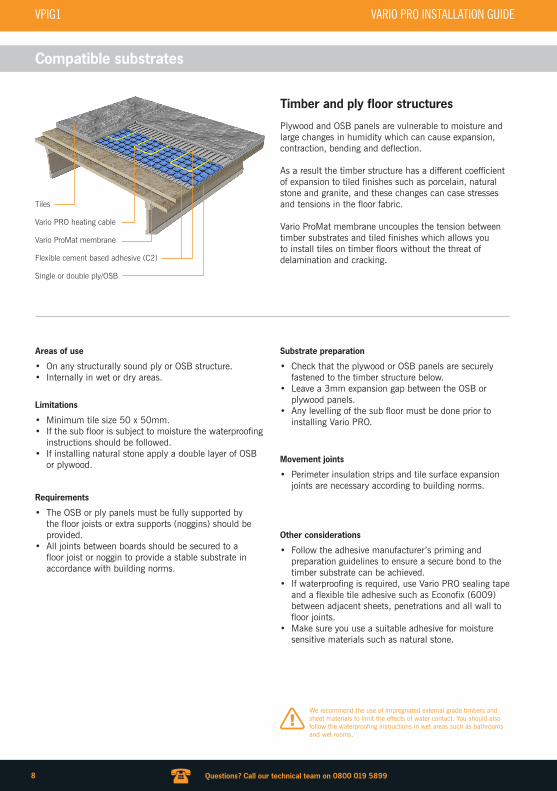
Tiles can be laid immediately after installing the heating cables. Use the flat side of the trowel to fill the cavities of the membrane with class C2 adhesive. Apply another layer of adhesive large enough for one tile with a trowel.
According to building norms, heating cables must be covered with a 5mm layer of adhesive. Check that your adhesive layer complies with these guidelines.
Apply adhesive to the back of the tile with the notched trowel and lay them on the layer of adhesive previously applied. Remove some tiles and check the back of the tile is fully covered with adhesive. Apply more if required.
After laying the tiles, repeat all of the tests and record the values on p20, to allow the end user to register their warranty online at www.thermogroupuk.com.
Laying tiles over Vario PRO
1. Spread adhesive on the substrate
3. Check adhesive thickness
2. Apply adhesive to the back of the tile
4. Complete the testing procedure
WARNING: Take care not to damage the heating cable with the notched trowel when applying adhesive to the membrane. Use of a rubber or plastic trowel is recommended.!
WARNING: Full coverage on the back of the tile may vary depending on the consistency of the adhesive, the angle of application with the trowel and the back surface of the tile. If full back coverage is not achieved, remove the tile and apply the new adhesive paying attention to the consistency. In the case of large format tiles it is recommended to double spread adhesive.
!
Other floor finishes
In some cases it may be necessary to install other floor finishes such as laminate, engineered board, vinyl or carpet over the Vario PRO system. Before doing so you should check that your desired floor finish is suitable for use with electric underfloor heating and ensure the thermostat is set up to limit the temperature to the manufacturer’s maximum temperature guidelines.
Vario PRO must be covered with a 10mm layer of flexible self levelling compound before installing floor finishes other than tiles.
Self levelling compound
Vario PRO systems can be covered with a flexible self levelling compound before tiling if preferred. Follow the self levelling manufacturer’s guidelines.
5mm
VARIO PRO INSTALLATION GUIDE VPIG1
DRAFT COPY
17
WWW. WWW. WWW. WWW. WWW.
Questions? Call our technical team on 0800 019 5899
Thermostat wiring diagram
E a r t h
127 6 5 4 3
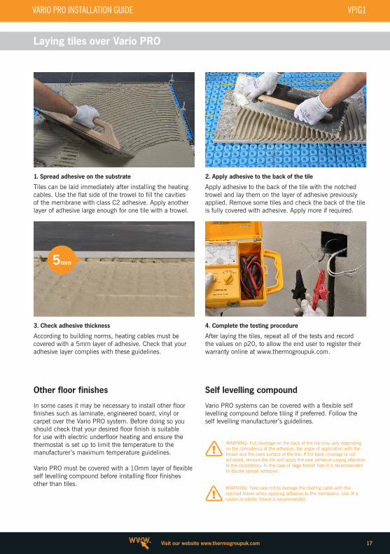
Connecting your thermostat
Thermogroup UK thermostats must be installed by a qualified electrician in accordance with all applicable safety regulations. The electrical wiring must conform to the latest revision of the IEE wiring regulations.
We recommend installing the thermostat into flush mounted plastic electrical box.
The diagram shows the connections to the 5259 Touchscreen Programmable Thermostat for illustrative purposes only. Check your thermostat installation guide for accurate wiring digrams.
1. Sensor probe2. Heating cable cold tail3. Power supply
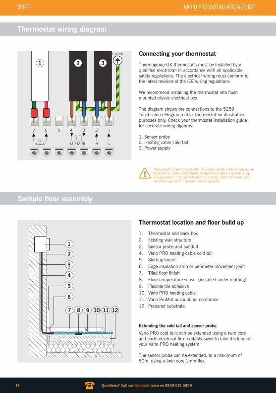
Thermostat location and floor build up
1. Thermostat and back box2. Existing wall structure3. Sensor probe and conduit4. Vario PRO heating cable cold tail5. Skirting board6. Edge insulation strip or perimeter movement joint7. Tiled floor finish8. Floor temperature sensor (installed under matting)9. Flexible tile adhesive10. Vario PRO heating cable11. Vario ProMat uncoupling membrane12. Prepared substrate
1 2 3
Sample floor assembly
Thermostats should be connected to a single phase mains supply via an RCD with a suitably rated fused isolator switch fitted. The fuse rating is dependent on the overall load of the system. Check the thermostat installation guide for maximum switching loads.
!
Vario PRO cold tails can be extended using a twin core and earth electrical flex, suitably sized to take the load of your Vario PRO heating system.
The sensor probe can be extended, to a maximum of 50m, using a twin core 1mm flex.
Extending the cold tail and sensor probe
1
2
3
4
5
6
8 9 10 11 127
VPIG1 VARIO PRO INSTALLATION GUIDE
18
WWW. WWW. WWW. WWW. WWW. Visit our website www.thermogroupuk.com
Example system layouts
w.c.
Shower
Basin
BasinW.C.
Bath
Kitchen units
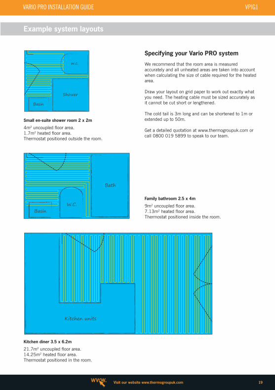
Specifying your Vario PRO system
We recommend that the room area is measured accurately and all unheated areas are taken into account when calculating the size of cable required for the heated area.
Draw your layout on grid paper to work out exactly what you need. The heating cable must be sized accurately as it cannot be cut short or lengthened.
The cold tail is 3m long and can be shortened to 1m or extended up to 50m.
Get a detailed quotation at www.thermogroupuk.com or call 0800 019 5899 to speak to our team.
4m2 uncoupled floor area.1.7m2 heated floor area.Thermostat positioned outside the room.
21.7m2 uncoupled floor area.14.25m2 heated floor area.Thermostat positioned in the room.
Small en-suite shower room 2 x 2m
9m2 uncoupled floor area.7.13m2 heated floor area.Thermostat positioned inside the room.
Family bathroom 2.5 x 4m
Kitchen diner 3.5 x 6.2m
VARIO PRO INSTALLATION GUIDE VPIG1
DRAFT COPY
19

WWW. WWW. WWW. WWW. WWW.
Questions? Call our technical team on 0800 019 5899
Test results and customer handover
Stock No Manufacturer’s Values
Before installation After cableinstallation
After tile installation
Resistance measurement of the electric heating cable
Two conductors and earth braid continuity test
Infinity (I) orOverload (OL)
Insulation resistance test between conductor cables and earth braid
Equal to or greater than 1 G Ω
Floor temperature sensor test
Qualified Installer
Name:
Email:
Phone:
Address:
Postcode:
Part P No:
Signature:
End User / Home Owner
Name:
Email:
Phone:
Address:
Postcode:
Date:
Signature:
The installer must complete the full test procedure, record all results on the table below and present this document along with a completed system diagram to the end user/home owner to allow them to complete the warranty activation. A warranty will not be granted unless this information has been completed in full and submitted via the online form - www.thermogroupuk.com.
!
VPIG1 VARIO PRO INSTALLATION GUIDE
20

WWW. WWW. WWW. WWW. WWW. Visit our website www.thermogroupuk.com
Use the grid to draw your final layout
VARIO PRO INSTALLATION GUIDE VPIG1
DRAFT COPY
21

WWW. WWW. WWW. WWW. WWW.
Questions? Call our technical team on 0800 019 5899
Electrical regulationsAll electrical connections must be made by a qualified electrician and conform to the latest edition of The IEE Wiring Regulations.
Electrical installations must comply with all applicable regulations, particularly for wet locations containing electric cables systems.
Substrate preparationAny substrate levelling must be completed before you install a Vario PRO system.
We recommend the installation of a suitable insulation board below Vario PRO in ground floor installations, over un-insulated substrates or unheated rooms.
Vario PRO should never be installed over highly flammable construction materials.
Before installing Vario PRO the substrate must be level, load bearing, and free from any substances that may weaken the bond between the membrane and substrate.
Compatible adhesivesYou must use an adhesive suitable for the specific type of substrate in your project. The adhesive must bond strongly to the substrate and set mechanically into the anchoring fleece on the under side of Vario PRO.
A standard flexible dry set adhesive is suitable for most substrates. It is possible to use an acrylic based emulsion adhesive in cases where the substrate is not compatible with standard dry set tile adhesives.
It is the installer’s responsibility to check the compatibility of all materials.
Any adhesive used with Vario PRO must be suitable for use with electric underfloor heating systems.
Information about the heating cablesWhen installing Vario PRO heating cables in any rooms it is important not to install heating cables in areas under permanent fixtures such as toilets, kitchen units, walls and pillars.
• Never kink Vario PRO heating cables.• Heating cables must not touch or cross over.• Heating cables must not cross expansion joints.• Never cut or shorten the heating cables.• Never join heating cables in series.• An suitably rated earth leakage circuit breaker (30mA)
must be included in the electrical installation.• Vario PRO cables should not be installed at
temperatures below 5°C.• Never kink the cold tail connection sleeves. The
smallest permissible bending radius is five times the outside diameter of the heating cable.
Important
Heating cables must be installed at least 30mm away from water pipes, pillars and other conductive construction components.
Heating cables and temperature sensors must be installed away from other heat sources such as lighting equipment and chimney breasts and flues.
Wear suitable footwear with rubber soles when installing Vario PRO and step on the cables as little as possible. If high traffic is expected use boards to cover and protect the heating cables and uncoupling membrane.
Covering the heating cablesVario PRO heating cables and cold tail connection sleeves must be fully embedded in the tile adhesive. Failure to do so will void any warranty and may result in product failure.
Heating cables must be fully enclosed in tile adhesive to prevent air gaps. Regulations state the requirement for a covering thickness of at least 5mm over the heating cables. The heating/cold tail connection must also be fully covered in a suitable tile adhesive.
Thermostats & electrical connectionsIn addition to these installation instructions, the applicable installation instructions for the chosen thermostat must also be observed. Connection cables must be installed in plastic conduits with a minimum wall thickness of 0.8mm.
The heating cables must to be connected to the mains voltage 230V~ and switched through the thermostat.
If more than one heating circuit is to be installed, all connection cables must be run through the empty conduit into the thermostat or flush socket and connected via the supplied system connection.
Thermostat sensor probes and heating system cold tails should not touch or cross over the heating cables.
Heating circuits can be switched through a single shared system connection even if they differ in size. Several heating cables should be connected in parallel. The maximum load (A) of the thermostat must be taken into account.
Floor finishes and coveringsOnce the heating cables have been installed and tested, tiles can be installed in the thin set method, using a thin set adhesive that meets the requirements of the covering.
It is helpful to fill the grooves of the uncoupling membrane in a single step, using the smooth side of a notched trowel (heating cables and sleeves must be fully enclosed by tile adhesive). Then use the notched trowel to
VPIG1 VARIO PRO INSTALLATION GUIDE
22

WWW. WWW. WWW. WWW. WWW. Visit our website www.thermogroupuk.com
Important
apply the thin set adhesive. The tiles are fully embedded in this layer.Cabinets with full floor contact as well as built-in cabinets may only be set up on unheated areas. No penetrating attachment parts (anchored screws for doorstops etc.) may be set up in areas where heating cables are installed.
Additional layers over the floor covering (e.g. rugs) thicker than 10mm are not permissible as they can cause heat accumulation, which may result in damage to the heating cables and floor finish.
For reasons of thermal efficiency, covering thicknesses over 30mm are not recommended.
Testing the systemPerform an insulation test before covering the heating cables in adhesive to measure the resistance of the heating cables and enter the value in the enclosed test log. Follow the full testing procedure and complete the results table on p20.
Customer handover procedureAttach a warning label for the heating cables with an installation plan and wiring diagram close to the electrical distribution box or consumer unit.
The following documentation must be issued to the end user/home owner for their records:
• Installation instructions with completed test results• System plan including temperature sensor heating
cable thermostat locations.• A full description of the floor assembly
Warranty registrationThe warranty registration process must be completed by the end user/home owner and is registered to the property. The installer is responsible for completing the test procedure, completing the customer handover form on p20 and handing a copy of all required documentation to the end user/home owner. Failure to do so will prevent the end user form registering their warranty. The warranty form should be completed online at www.thermogroupuk.com. Thermogroup UK will then verify test data and issue a warranty confirmation by post within 5-10 working days.
Don’t forget to activate your lifetime warranty online!
Tweet and win!Follow @thermonet_ufh on twitter and tweet a photo of your installation using #underfloorheating and you could win a Google Nexus 7!
www.thermogroupuk.com/warranty-registration
Wireless control fromyour smartphone
Thermotouch 3.2aP
Download the app and try demo mode for free!
iOS, Android, Windows
VARIO PRO INSTALLATION GUIDE VPIG1
DRAFT COPY
23

Thermogroup UK Bridge House
Hop Pocket Lane Paddock Wood
Kent TN12 6DQ
E&OE © Thermogroup UK 2015
0800 019 [email protected]
www.thermogroupuk.com
Vario™ ProMat Membrane
STOCKNO
SIZEM
AREAM2
109500 15 x 1 15
Vario™ ProMat Sealing Tape
STOCKNO
SIZEM
109510 50
Vario™ PRO Heating Cable
STOCKNO
RESISTANCEΩ
AREA M2(130W/M2)
LENGTHM
OUTPUTW
109012 352.7 1.14 12 150
109018 235.1 1.71 18 225
109025 176.3 2.38 25 300
109031 141.1 3.04 31 375
109037 117.6 3.52 37 450
109050 88.2 4.75 50 600
109062 70.5 5.80 61 750
109075 58.8 7.13 75 900
109100 44.1 9.50 100 1200
109125 35.3 11.88 125 1500
109150 29.4 14.25 150 1800
109200 22.0 19.00 200 2400
The areas detailed in the left hand table are designed to give an output of 130W/m2
(3 dimple spacing)
VPIG1 VARIO PRO INSTALLATION GUIDE