Variable Refrigerant Flow (VRF) System - Wireless Remote ... · Variable Refrigerant Flow (VRF)...
3
6 7 3 2 August 2013 © 2013Trane All rights reserved 4 5 1 User Guide Variable Refrigerant Flow (VRF) System Wireless Remote Control Model Number: TVCTRLTRDH00UT TVCTRLTRDH00UA SAFETY WARNING Only qualified personnel should install and service the equipment.The installation, starting up, and servicing of heating, ventilating, and air-conditioning equipment can be hazardous and requires specific knowledge and training. Improperly installed, adjusted or altered equipment by an unqualified person could result in death or serious injury. When working on the equipment, observe all precautions in the literature and on the tags, stickers, and labels that are attached to the equipment. WARNING Indicates a potentially hazardous situation which, if not avoided, could result in death or serious injury. CAUTIONs Indicates a potentially hazardous situation which, if not avoided, could result in minor or moderate injury. It could also be used to alert against unsafe practices. NOTICE: Indicates a situation that could result in equipment or property- damage only accidents. Important: Environmental Concerns! Scientific research has shown that certain man-made chemicals can affect the earth's naturally occurring stratospheric ozone layer when released to the atmosphere. In particular, several of the identified chemicals that may affect the ozone layer are refrigerants that contain Chlorine, Fluorine and Carbon (CFCs) and those containing Hydrogen, Chlorine, Fluorine and Carbon (HCFCs). Not all refrigerants containing these compounds have the same potential impact to the environment.Trane advocates the responsible handling of all refrigerants-including industry replacements for CFCs such as HCFCs and HFCs. Important: Responsible Refrigerant Practices! Trane believes that responsible refrigerant practices are important to the environment, our customers, and the air conditioning industry. All technicians who handle refrigerants must be certified.The Federal Clean Air Act (Section 608) sets forth the requirements for handling, reclaiming, recovering and recycling of certain refrigerants and the equipment that is used in these service procedures. In addition, some states or municipalities may have additional requirements that must also be adhered to for responsible management of refrigerants. Know the applicable laws and follow them. WARNING Personal Protective Equipment Required! Installing/servicing this unit could result in exposure to electrical, mechanical and chemical hazards. Before installing/servicing this unit, technicians MUST put on all Personal Protective Equipment (PPE) recommended for the work being undertaken. ALWAYS refer to appropriate MSDS sheets and OSHA guidelines for proper PPE.When working with or around hazardous chemicals,ALWAYS refer to the appropriate MSDS sheets and OSHA guidelines for information on allowable personal exposure levels, proper respiratory protection and handling recommendations. If there is a risk of arc or flash, technicians MUST put on all necessary Personal Protective Equipment (PPE) in accordance with NFPA70E for arc/flash protection PRIOR to servicing the unit. Failure to follow recommendations could result in death or serious injury. WARNING Proper FieldWiring and Grounding Required! All field wiring MUST be performed by qualified personnel. Improperly installed and grounded field wiring poses FIRE and ELECTROCUTION hazards.To avoid these hazards, you MUST follow requirements for field wiring installation and grounding as described in NEC and your local/state electrical codes. Failure to follow code could result in death or serious injury. Components Ensure that the following accessories are present: Figure 1. Wireless remote control accessories Wireless remote control Batteries (2) M4XL16 screws Remote control holder Manuals Find a suitable location for the holder and attach it to the wall. Remote Control Holder Location Install the remote control holder in a location that meets the following requirements: • No interference to the remote control signal • No exposure to direct sunlight or heat source • More than 3.28 ft (1m) away from a television or stereo system Installation Mount the holder as follows: 1. Mark the spots where you will install remote control holder by a pencil. 2. Drill the marked holes (2 each) for screws on the wall. 3. Install the remote control holder on the wall by using the screws. Figure 2. Mounting the control holder Wireless Remote Control Figure 3. Buttons and their functions Remote control display Toggle button: Press once to silence the beep. Press again to re-activate. Increase/decrease temperature by 1°F +/- Notes: • 2ndF button changes the function of the Beep Off button to Room and Filter Reset button to Blade.To restore the button function to Beep Off and Filter Reset, press the 2ndF button again. • Functions not supported by your unit model will not operate, even if they appear on the remote control display. Operation To activate a control function, point the remote control towards the remote control receiver of the indoor unit. When you press a button on the remote control, you will hear a beep sound from the indoor unit. A transmit indicator (shown at left) appears on the remote control display. Notes: • There is a possibility that the indoor unit will not operate by remote control near strong light such as a fluorescent lamp or a neon sign. If this occurs, point the remote control at the remote control receiver of the indoor unit. • If the remote control is causing other electrical products to operated, call your nearest service center. Figure 4. Display Indicators Operating Modes Press the Mode button to select one of the following operating modes: Note: The system may not respond to the remote control signal if the building is currently operating in a mode that is in conflict with the mode you are requesting (for example, a request for cooling when the building is currently heating, or vice versa). Auto In Auto mode, the indoor unit automatically sets the temperature and fan speed to maintain the selected temperature. If the indoor temperature is too high, a cooling breeze is generated until the room returns to a comfortable level. As the room cools, the fan slows down and maintains a gentle airflow. Cool Cool mode is frequently used and you can freely control the temperature, fan speed, and air flow direction in cool mode. When you select heat mode while the unit is in cool mode, the cool mode request is canceled. Dry The unit in Dry mode acts like a dehumidifier by removing moisture from the indoor air. Fan In Fan mode, you can ventilate your room. Fan operation helps to maintain a satisfactory indoor environment. Heat While the unit is in heat mode, be aware of the following: • There may be a delay before the fan begins running to avoid generating a cold breeze. • The defrost indicator (shown at left) will appear when frost is being removed from the outdoor unit. When the defrost function is completed, the defrost indicator disappears. • If you stop heating operation, the fan will continue running for a period of time to cool the unit. • If you select cool mode while the unit is in heat mode, the heat mode request is canceled. Basic operation tasks Perform the following basic operation tasks: Press the Power button on the unit. Press the Mode button to set the operating mode. Each time you press the Mode button, the mode changes in the following order: Auto, Cool, Dry, Fan, and Heat. Press the Fan button to set the desired fan speed. VRF-SVU40A-EN
Transcript of Variable Refrigerant Flow (VRF) System - Wireless Remote ... · Variable Refrigerant Flow (VRF)...
6 7
32
August 2013 © 2013TraneAll rights reserved
4 5
1
User Guide
Variable Refrigerant Flow (VRF) SystemWireless Remote Control
Model Number: TVCTRLTRDH00UTTVCTRLTRDH00UA
SAFETY WARNING
Only qualified personnel should install and service the equipment.The installation,starting up, and servicing of heating, ventilating, and air-conditioning equipment canbe hazardous and requires specific knowledge and training. Improperly installed,adjusted or altered equipment by an unqualified person could result in death orserious injury. When working on the equipment, observe all precautions in theliterature and on the tags, stickers, and labels that are attached to the equipment.
WARNINGIndicates a potentially hazardous situation which, if not avoided,could result in death or serious injury.
CAUTIONsIndicates a potentially hazardous situation which, if not avoided,could result in minor or moderate injury. It could also be used toalert against unsafe practices.
NOTICE: Indicates a situation that could result in equipment or property-damage only accidents.
Important: Environmental Concerns! Scientific research has shownthat certain man-made chemicals can affect the earth's naturally occurringstratospheric ozone layer when released to the atmosphere. In particular,several of the identified chemicals that may affect the ozone layer arerefrigerants that contain Chlorine, Fluorine and Carbon (CFCs) and thosecontaining Hydrogen, Chlorine, Fluorine and Carbon (HCFCs). Not allrefrigerants containing these compounds have the same potential impactto the environment.Trane advocates the responsible handling of allrefrigerants-including industry replacements for CFCs such as HCFCs andHFCs.Important: Responsible Refrigerant Practices!Trane believes thatresponsible refrigerant practices are important to the environment, ourcustomers, and the air conditioning industry. All technicians who handlerefrigerants must be certified.The Federal Clean Air Act (Section 608) setsforth the requirements for handling, reclaiming, recovering and recycling ofcertain refrigerants and the equipment that is used in these serviceprocedures. In addition, some states or municipalities may have additionalrequirements that must also be adhered to for responsible management ofrefrigerants. Know the applicable laws and follow them.
WARNING
Personal Protective Equipment Required!Installing/servicing this unit could result in exposure to electrical, mechanical andchemical hazards. Before installing/servicing this unit, technicians MUST put on allPersonal Protective Equipment (PPE) recommended for the work beingundertaken. ALWAYS refer to appropriate MSDS sheets and OSHA guidelines forproper PPE.When working with or around hazardous chemicals, ALWAYS refer tothe appropriate MSDS sheets and OSHA guidelines for information on allowablepersonal exposure levels, proper respiratory protection and handlingrecommendations. If there is a risk of arc or flash, technicians MUST put on allnecessary Personal Protective Equipment (PPE) in accordance with NFPA70E forarc/flash protection PRIOR to servicing the unit. Failure to followrecommendations could result in death or serious injury.
WARNING
Proper Field Wiring and Grounding Required!All field wiring MUST be performed by qualified personnel. Improperly installedand grounded field wiring poses FIRE and ELECTROCUTION hazards.To avoidthese hazards, you MUST follow requirements for field wiring installation andgrounding as described in NEC and your local/state electrical codes. Failure tofollow code could result in death or serious injury.
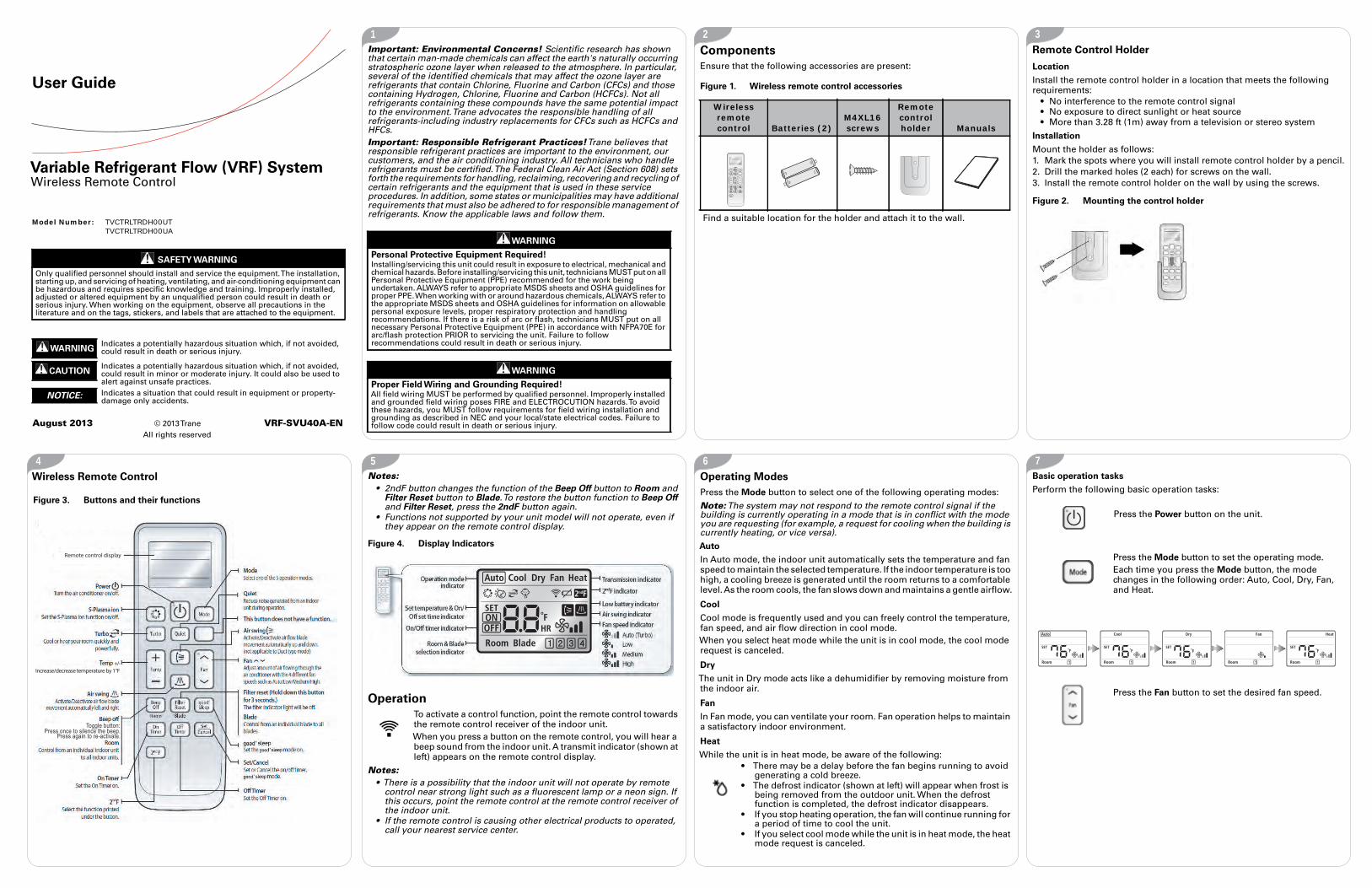
Components
Ensure that the following accessories are present:
Figure 1. Wireless remote control accessories
Wireless remote control Batteries (2)
M4XL16 screws
Remote control holder Manuals
Find a suitable location for the holder and attach it to the wall.
Remote Control Holder
Location
Install the remote control holder in a location that meets the followingrequirements:
• No interference to the remote control signal• No exposure to direct sunlight or heat source• More than 3.28 ft (1m) away from a television or stereo system
Installation
Mount the holder as follows:1. Mark the spots where you will install remote control holder by a pencil.2. Drill the marked holes (2 each) for screws on the wall.3. Install the remote control holder on the wall by using the screws.
Figure 2. Mounting the control holder
Wireless Remote Control
Figure 3. Buttons and their functions
Remote control display
Toggle button: Press once to silence the beep.
Press again to re-activate.
Increase/decrease temperature by 1°F+/-
Notes:• 2ndF button changes the function of the Beep Off button to Room and
Filter Reset button to Blade.To restore the button function to Beep Offand Filter Reset, press the 2ndF button again.
• Functions not supported by your unit model will not operate, even ifthey appear on the remote control display.
Operation
To activate a control function, point the remote control towardsthe remote control receiver of the indoor unit.When you press a button on the remote control, you will hear abeep sound from the indoor unit. A transmit indicator (shown atleft) appears on the remote control display.
Notes:• There is a possibility that the indoor unit will not operate by remote
control near strong light such as a fluorescent lamp or a neon sign. Ifthis occurs, point the remote control at the remote control receiver ofthe indoor unit.
• If the remote control is causing other electrical products to operated,call your nearest service center.
Figure 4. Display Indicators
Operating Modes
Press the Mode button to select one of the following operating modes:
Note:The system may not respond to the remote control signal if thebuilding is currently operating in a mode that is in conflict with the modeyou are requesting (for example, a request for cooling when the building iscurrently heating, or vice versa).
Auto
In Auto mode, the indoor unit automatically sets the temperature and fanspeed to maintain the selected temperature. If the indoor temperature is toohigh, a cooling breeze is generated until the room returns to a comfortablelevel.As the room cools, the fan slows down and maintains a gentle airflow.
Cool
Cool mode is frequently used and you can freely control the temperature,fan speed, and air flow direction in cool mode.When you select heat mode while the unit is in cool mode, the cool moderequest is canceled.
Dry
The unit in Dry mode acts like a dehumidifier by removing moisture fromthe indoor air.
Fan
In Fan mode, you can ventilate your room. Fan operation helps to maintaina satisfactory indoor environment.
Heat
While the unit is in heat mode, be aware of the following:• There may be a delay before the fan begins running to avoid
generating a cold breeze.• The defrost indicator (shown at left) will appear when frost is
being removed from the outdoor unit. When the defrostfunction is completed, the defrost indicator disappears.
• If you stop heating operation, the fan will continue running fora period of time to cool the unit.
• If you select cool mode while the unit is in heat mode, the heatmode request is canceled.
Basic operation tasks
Perform the following basic operation tasks:
Press the Power button on the unit.
Press the Mode button to set the operating mode.Each time you press the Mode button, the modechanges in the following order: Auto, Cool, Dry, Fan,and Heat.
Press the Fan button to set the desired fan speed.
VRF-SVU40A-EN

8 9 10 11
12 13 14 15
Auto
Cool
Dry
Fan
Heat
Press the Temp button to adjust the desired temperature.
Auto You can adjust the desired temperature by 1°F within the range of 65°F–86°F.
Cool Cool You can adjust the desired temperature by 1°F within the range of 65°F–86°F.
Dry Dry You can adjust the desired temperature by 1°F within the range of 65°F–86°F.
Fan Fan Temperature adjustment is not possible.Heat Heat You can adjust the desired temperature by 1°F within the range of
61°F–86°F.
(Auto)
(Auto) (Low) (Med) (High)
(Auto)
(Auto) (Med)(Low) (High)
(Auto) (Med)(Low) (High)
Turbo Operation
UseTurbo operation to heat or cool a room quickly.Press theTurbo button (shown at left) on the remote control whilein Cool/Heat mode.TheTurbo indicator (shown at left) appears on the remotecontroller display and the unit operates inTurbo function for 30minutes. If you press theTurbo button again, theTurbo operationis canceled.
Be aware of these additional facts:• Turbo function is only available in the Cool/Heat mode.• If you select theTurbo operation during the Quiet operation, the Quiet
operation is canceled.• You can adjust the air flow direction Up/Down or Left/Right.• You cannot adjust the set temperature and fan speed.
Figure 5. Buttons used to start theTurbo function
Quiet Operation
Use this function to reduce the noise generated during air conditionoperation.Press the Quiet button to select Quiet Operation. If you press the Quietbutton once again, the Quiet operation is canceled.
Note:You can select the Quiet operation while the unit is in cool or heatmode. If you select the Quiet operation during theTurbo operation, theTurbo operation is canceled.
In Cool mode:You can adjust the desired temperature by 1°F within the range of 65°F–86°F.
In Heat mode:You can adjust the desired temperature by 1°F within the range of 61°F–86°F.
Since the fan speed is fixed as Auto, the fan speed is not controlled by Fan speed button.
You can set the air flow direction Up/Down or Left/Right.
Air Swing Operation
Note: Air Swing operation is available only with high-wall and convertibleceiling/floor indoor units.This function allows you to shift the air flow direction up and down or leftand right.
1.Press the vertical or horizontal swing button (shown at left) tomove the air flow direction up and down or left and right whilethe unit is on.2.When the blade reaches the desired position, press the verticalor horizontal swing button one more time to set the air flowdirection.The up/down and left/right tilting of the blade will stop.
Figure 6. Button used to start Quiet operation
Figure 7. Buttons used to start Air Swing operation
Sleep Mode
Note: Sleep mode is available only with high-wall indoor units.In this mode, the unit will operate in Fall asleep > Sound sleep > Wake upfrom Sleep mode.When the unit is operating in Cool mode
1. Press the good’ sleep button on the remote control to select Sleep Mode.The good’ sleep indicator appears and the OffTimer indicator startsblinking on the remote control display.
2. Press the good’ sleep button repeatedly to set the off time.• You can set the time in half-hour units from 30 minutes to 3 hours and
hourly units from 3 hours to 12 hours.• The operation hours can be set from a minimum of 30 minutes to a
maximum of 12 hours.• The default number of operation hours is set to 8 hours.
3. Press the Set/Cancel button to activate Sleep Mode.The OffTimerindicator stops blinking and the set time is displayed.
Note: Press the Set/Cancel button to start Sleep Mode within 10 seconds orthe operation will be canceled. Check the Off indicator on the remote controldisplay to be sure your off time is in effect.To cancel Sleep Mode, press the Set/Cancel button once again.
Figure 8. Button used to start Sleep Mode operation
Sleep Modes
Fall asleep mode. Provides you with a comfortable sleep environment byrapidly cooling the room.Sound sleep mode. The sound sleep mode adjusts temperature and airflow to maintain a healthy skin temperature and promote deep sleep.Thesound sleep hours can be longer or shorter depending on any change to theSleep Mode hours.Wake up from Sleep mode. Provides air flow that adjusts your bodytemperature, so you wake up feeling refreshed.
Note:• The recommended temperature setpoint is 77°F–81°F (25°C–27°C).The
recommended ideal temperature is 79°F (26°C).• If Sleep mode is set to < 4 hours, the operation will automatically stop
after the set number of hours has passed. If Sleep mode is set > 5 hours,
Temperature, fan speed, and air flow direction adjustments
You can set the desired temperature by 1°F within the range of 65°F–86°F.
The fan speed is adjusted automatically according to the Sleep mode.
The air flow direction is adjusted automatically according to the Sleep mode.
the unit will run inWake up mode during the last hour before operationautomatically stops.
• If you press theTurbo, Mode, or Quiet button during Sleep mode, Sleepmode operation is canceled and the selected mode of operation starts.
• If both the OnTimer/OffTimer and Sleep mode OffTimer functionshave been set, only the timer set last is applied.
On/OffTimer
You can set the unit to turn on/off automatically at the desired time.
Setting the OnTimer while the unit is off / Setting the OffTimer whilethe unit is on
1. Press OnTimer or OffTimer button.(On) / (Off) timer indicator blinks on the remote controller display.
2. Press OnTimer or OffTimer button repeatedly to set the time.You can set the time in half-hour units, from 30 minutes to 3 hours; andhour units, from 3 hours to 24 hours.The set hour is set to minimum 30 minutes and maximum 24 hours.
3. Press Set/Cancel button to activate it.(On) / (Off) indicators stop blinking and the set time is displayed.
Note:You must press the Set/Cancel button within 10 seconds afterselecting the OnTimer or OffTimer button or the unit will return to theprevious status. Check the On or Off indicator on the remote control displayto be sure your requested status is in effect.To cancel operation, press the Set/Cancel button once again.
Figure 9. Setting the OnTimer
Figure 10. Setting the OffTimer

16 17 18 19
The manufacturer optimizes the performance of homes and buildings around the world. Abusiness of Ingersoll Rand, the leader in creating and sustaining safe, comfortable andenergy efficient environments, the manufacturer offers a broad portfolio of advancedcontrols and HVAC systems, comprehensive building services, and parts. For moreinformation, visit www.IRCO.com.
The manufacturer has a policy of continuous product and product data improvement and reservesthe right to change design and specifications without notice.
© 2013Trane All rights reservedVRF-SVU40A-EN 15 Aug 2013New
We are committed to usingenvironmentally consciousprint practices that reducewaste.
Additional options available in OnTimer mode
The following additional options are available in OnTimer mode:
Notes:• If both the OnTimer/OffTimer and Sleep mode OffTimer functions
have been set, only the timer set last is applied.• About 10 seconds after setting the OnTimer, the set time will be
displayed on the remote controller.
Setting the OnTimer and OffTimer simultaneously
Notes:• The OnTimer and OffTimer setting times must be different from each
other.• If you press the Set/Cancel button or Power button while the both On
Timer and OffTimer are set simultaneously, the functions of both theOnTimer and OffTimer are canceled at the same time.
You can select from Auto > Cool > Dry > Fan > Heat.
You can set the desired temperature by 1°F within the range of 65°F–86°F.
If the unit is on and the preset time on the On Timer is shorter than the time set on the Off Timer
If the unit is off and the preset time on the On Timer is longer than the time set on the Off Timer
For example, if the On Timer is set for 3 hours and the Off Timer is set for 5 hours:
• The unit will turn on after 3 hours from the moment you have set the timer.
• Your unit will remain on for 2 hours and then turn off automatically.
For example, if the On Timer is set for 3 hours, and the Off Timer is set for 1 hour:
• The unit will turn off after 1 hour from the moment you have set the timer.
• After 2 hours, your unit will turn on.
Selecting Rooms
You can operate up to four indoor units separately.1. With the unit powered on, press the 2ndF button and then press Beep
Off/Room button.2. Select indoor unit from 1 to 4, one at a time, or select all the indoor units
by pressing the Room button repeatedly.
Figure 11. Buttons used to select rooms
Selecting Blades
Note: Blade selection is available only with cassette indoor units.You can operate the four fan blades individually.While the unit is on, press the 2ndF button andselect the blade you want to operate by pressingthe Filter Reset/Blade button and then pressingthe vertical Air Swing button. By pressing theBlade button repeatedly, you can select one ormore individual blades or all blades.Press the horizontalAir Swing button to cancel theselected blade.
Note: When selecting an individual blade, youcannot use the horizontal Air Swing button.
Figure 12. Buttons used to select blades
Vertical Air Swing button
Horizontal Air Swing button
Changing Batteries
When the battery is drained, the icon shown at left will appear inthe remote control display. When this occurs, replace the two1.5 V AAA batteries.
Storage
When you do not use the remote control for an extended period of time,remove the batteries and store the device.
Figure 13. Inserting the batteries
1. Push the leveras the arrowindicates on therear side of theremote control andpull up.
2. Insert two AAAbatteries.
Check and match the“+” and “-” signsaccordingly. Makesure you haveinserted the batteriesin the correct position.
3. Close the cover byplacing it back to itsoriginal position.
You should hear aclick sound when thecover is lockedproperly.