Variable Refrigerant Flow Systems - PDHonline.com · 2016-01-14 · VRF systems include...
39
An Approved Continuing Education Provider PDHonline Course M537 (3 PDH) Variable Refrigerant Flow Systems Instructor: Lee Layton, P.E 2016 PDH Online | PDH Center 5272 Meadow Estates Drive Fairfax, VA 22030-6658 Phone & Fax: 703-988-0088 www.PDHonline.org www.PDHcenter.com
Transcript of Variable Refrigerant Flow Systems - PDHonline.com · 2016-01-14 · VRF systems include...

An Approved Continuing Education Provider
PDHonline Course M537 (3 PDH)
Variable Refrigerant Flow
Systems
Instructor: Lee Layton, P.E
2016
PDH Online | PDH Center
5272 Meadow Estates Drive
Fairfax, VA 22030-6658
Phone & Fax: 703-988-0088
www.PDHonline.org
www.PDHcenter.com

www.PDHcenter.com PDHonline Course M537 www.PDHonline.org
© Lee Layton. Page 2 of 39
Table of Contents
Section Page
Introduction …………………………..…………… 3
Chapter 1, How a Heat Pump Works …….…….… 7
Chapter 2, How a VRF System Works ……….…. 15
Chapter 3, VRF Case Study ………….………..…. 24
Chapter 4, VRF Applications ………….……….... 29
Summary ……………………………….……..….. 39
Photo Credit: The Photo on the cover page is from Toshiba Industries and
shows its VRF R410A system.

www.PDHcenter.com PDHonline Course M537 www.PDHonline.org
© Lee Layton. Page 3 of 39
Introduction
Commercial buildings account for approximately 40% of the energy consumption in the United
States. About a third of commercial building energy usage is for heating, cooling and ventilation.
See the chart in Figure 1.
Figure 1
One HVAC technology that is in common usage outside of the United States and beginning to
enter the U.S. market is variable refrigerant flow (VRF) multi-split systems. These systems are
also referred to as variable refrigerant volume (VRV) systems. VRFs are packaged outdoor
compressor units connected through refrigerant lines to multiple refrigerant fan coil units in the
building.
Variable refrigerant flow (VRF) heating, ventilation, and air conditioning (HVAC) systems are
one possible tool to improve energy efficiency. They are the primary HVAC system choice in
Europe, Japan, China, and other parts of the world. VRF is particularly appropriate to existing
buildings that use excessive energy or need HVAC repair and upgrade for other reasons.
VRF has about 24% of the global commercial air conditioning market, and over 35% market
share in China, India, the European Union, and Eastern Europe. The VRF share of the U.S.

www.PDHcenter.com PDHonline Course M537 www.PDHonline.org
© Lee Layton. Page 4 of 39
market is still only about 3%, but multiple manufacturers sell these systems in the U.S. and sales
are growing. These manufacturers provide the products through an integrated supply system,
including installation and design training, and sometimes provide part or all of the design, as
well as quality control.
The U.S. market has been slower to accept VRF technology for several reasons. In Europe, many
buildings did not have air conditioning, and adding ductwork was expensive or nearly impossible
given space constraints. Europe has tended to provide cooling with chilled water fan coils rather
than ducted systems. The United States has a long history with ducted HVAC systems using both
direct expansion (DX) systems and chilled water systems..
VRF systems use refrigerant lines to distribute the refrigerant throughout the building, and since
VRF systems use more refrigerant than direct expansion systems this raises concerns about leaks
and compliance with ASHRAE Standard 15 Safety Standard for Refrigeration Systems which
regulates refrigerant safety and environmental and sustainability impacts.
VRF systems combine many of the features of other HVAC systems, which offer energy
efficiency with a limited number of components relative to systems with central plants. VRF
systems have limited space requirements, particularly for the distribution system inside the
building. VRF HVAC systems include two major components, a compressor unit and multiple
indoor fan coil units. The compressor unit cools and heats refrigerant connected through piping
to condition the building.
The compressor units are typically air cooled. Sometimes water-cooled units are used and are
connected to a cooling tower and boiler. These systems are capable of simultaneously cooling
some zones and heating others and can recover heat from spaces being cooled for use in spaces
being heated and vice versa. The compressor unit uses variable refrigerant flow and is controlled
by a variable-speed drive, which operate more efficiently than conventional compressors.
However, the complexity of the variable refrigerant flow compressor and controls results in
significantly more expensive compressor units than comparable conventional systems.
VRF systems include sophisticated controls integrated with the units that may not require a
separate building automation system, when such a system is part of the project requirements.
VRF systems include self-diagnostics and monitoring points, as well as the ability to
communicate with a wide variety of other building systems with non-proprietary building
automation communication protocols.
VRF is well suited to retrofit applications in older buildings because it can be added on to or
replace existing equipment in limited space, where there is currently limited or no ductwork.

www.PDHcenter.com PDHonline Course M537 www.PDHonline.org
© Lee Layton. Page 5 of 39
VRF may be the least expensive option in some of these cases, or may offer a reasonable
payback relative to other options.
Even though VRF HVAC systems are a mature technology, they are relatively new to the U.S.
market and important questions about the actual energy savings remain unanswered. Some
studies show that VRF systems can achieve 30% and higher HVAC energy cost savings relative
to older conventional systems, or older inefficient systems and a range of building types.
Costs and energy savings vary a great deal particularly for
retrofit projects. It is not possible to define a single payback
for the many applications of the systems, but there are
opportunities to achieve reasonable paybacks on investments
in VRF systems. Packaged rooftop units, constant-air volume
(CAV) and variable-air volume (VAV) with hot water or
electric reheat systems may have simple paybacks of 15 years
or less. Facilities managers should look for opportunities in
buildings whose energy usage is above-average for other,
similarly situated facilities. Chilled water VAV systems have
similar potential simple paybacks; however, there is not
enough information to clearly distinguish the incremental cost
and potential energy cost savings for air-cooled and water-
cooled chillers, or air-cooled and water-cooled VRF systems.
The best opportunities for VRF systems include buildings with these target characteristics:
Inefficient HVAC systems and high energy costs,
Lack of cooling or inadequate cooling capacity,
Older buildings with limited room to install or change systems,
New building projects that can take advantage of opportunities to reduce floor-to-floor
height, or increase usable floor space by removing mechanical equipment from inside the
main building areas,
VAV systems with electric reheat or heat pumps with electric back-up heat,
Significant heating requirements,
Inefficient fan systems,
Leaky or poorly designed or installed ductwork, and
Facilities already identified for HVAC upgrades, replacements, or energy improvements.
One significant barrier to the technology is the uncertainty in estimating savings. There is not a
complete, independently developed energy simulation protocol, nor is there commonly available
real energy savings results isolated to VRF savings.
Constant-air volume (CAV) is a type
of HVAC system that delivers supply air
at a constant flow rate, but in which the
supply temperature will vary to meet
variable thermal loads.
Variable Air Volume (VAV) is a type
of HVAC system that varies the airflow
at a constant temperature. The
advantages of VAV systems over
constant-volume systems include more
precise temperature control, reduced
compressor wear, lower energy
consumption by system fans, less fan
noise, and additional passive
dehumidification.

www.PDHcenter.com PDHonline Course M537 www.PDHonline.org
© Lee Layton. Page 6 of 39
This course reviews the basic operation of HVAC systems and then explains how Variable
Refrigerant Flow systems work. A case study, presented by the US General Services
Administration is reviewed and the various application factors concerning VRF systems are
discussed.

www.PDHcenter.com PDHonline Course M537 www.PDHonline.org
© Lee Layton. Page 7 of 39
Chapter 1
How a Heat Pump System Works
This chapter is a review of the basic operation of a
typical heat pump. Included is a review of the major
components of a heat pump as well as a discussion of
the operating cycles of a heat pump.
Overview
To move heat from a colder location to a warmer area
requires thermodynamic work. Heat pumps differ in
how they apply this work to move heat, but they can
essentially be thought of as heat engines operating in
reverse. A heat engine allows energy to flow from a
hot source to a cold heat sink, extracting a fraction of it as work in the process. Conversely, a
heat pump requires work to move thermal energy from a cold source to a warmer heat sink.
Since the heat pump uses a certain amount of work to move the heat, the amount of energy
deposited at the hot side is greater than the energy taken from the cold side by an amount equal
to the work required. Conversely, for a heat engine, the amount of energy taken from the hot side
is greater than the amount of energy deposited in the cold heat sink since some of the heat has
been converted to work.
A typical heat pump's refrigeration system consists of a compressor and two coils made of
copper tubing - one indoors and one outside - which are surrounded by aluminum fins to aid heat
transfer. In the heating mode, liquid refrigerant in the outside coils extracts heat from the air and
evaporates into a gas. The indoor coils release heat from the refrigerant as it condenses back into
a liquid. A reversing valve, near the compressor, can change the direction of the refrigerant flow
for cooling as well as for defrosting the outdoor coils in winter.
In HVAC applications, a heat pump normally refers to a vapor-compression refrigeration device
that includes a reversing valve and optimized heat exchangers so that the direction of heat flow
may be reversed. The reversing valve switches the direction of refrigerant through the cycle and
therefore the heat pump may deliver either heating or cooling to a building. In the cooler
climates the default setting of the reversing valve is heating. The default setting in warmer
climates is cooling. Because the two heat exchangers, the condenser and evaporator, must swap
functions, they are optimized to perform adequately in both modes. As such, the efficiency of a
reversible heat pump is typically slightly less than two separately-optimized machines.

www.PDHcenter.com PDHonline Course M537 www.PDHonline.org
© Lee Layton. Page 8 of 39
When outdoor temperatures fall below between 25-30F, an alternate source of heating is
required. Often low-efficient, electric resistance coils are used for heating. Because of the need
for auxiliary heat, air-source heat pumps aren't always very efficient for heating in areas with
cold winters. Some units now have gas-fired backup furnaces instead of electric resistance coils,
allowing them to operate more efficiently.
Most central heat pumps are split-systems—that is, they each have one coil indoors and one
outdoors. Supply and return ducts connect to a central fan, which is located indoors. Some heat
pumps are packaged systems. These usually have both coils and the fan outdoors. Heated or
cooled air is delivered to the interior from ductwork that protrudes through a wall or roof.
A heat pump actually delivers more heat output than the equivalent of the electric input it uses. It
is not uncommon for a heat pump to deliver 250% to 400% more heat than would be obtained
from an equivalent electric resistance heating system.
The efficiency and performance of today's air-source heat pumps is one-and-a-half to two times
greater than those available 30 years ago. This improvement in efficiency has resulted from
technical advances and options such as these:
Thermostatic expansion valves for more precise control of the refrigerant flow to the
indoor coil.
Variable speed blowers, which are more efficient and can compensate for some of the
adverse effects of restricted ducts, dirty filters, and dirty coils.
Improved coil design.
Improved electric motor and two-speed compressor designs.
Copper tubing, grooved inside to increase surface area.
The most common heat pumps use electrically-driven compressors. However, in addition to
electrically driven compressors, natural gas-driven heat pumps are commercially available. In
one example, the gas-fired heat pump uses the absorption cycle, where the energy for refrigerant
compression is provided by a gas burner. Another approach is to use a natural gas fired engine
to drive the heat pump. In this case, a natural gas engine is used to drive the compressor. During
operation, heat is recovered from the engine jacket cooling water and engine exhaust. Gas heat
pumps are less common than electric heat pumps and performance compared to electric heat
pumps is lower, with lower Coefficient’s of Performance (COP) for both absorption and engine-
driven units than for conventional electric heat pumps. The inherent variable-speed capability
of an engine offers part-load efficiency advantages compared to single speed electric compressor
drives. They promise to reduce global warming through more efficient conversion of natural
gas and reduced emissions from electric power plants as they do not use electricity to drive the
heat pump.

www.PDHcenter.com PDHonline Course M537 www.PDHonline.org
© Lee Layton. Page 9 of 39
Heat Pump Components
A heat pump system consists of the compressor, heat exchange coils, reversing valve, expansion
device, defrost controls, accumulator, crankcase heater, refrigerant, and thermostat. We will
look at each of these briefly.
Compressor
The primary component in a heat pump is the compressor. A compressor pumps
refrigerant around the refrigerant circuit, and increases the pressure of the
refrigerant vapor. This increase in pressure allows the refrigerant to condense at
a higher temperature. Refrigerant vapor always flows through the compressor in
the same direction – it enters the suction pipe at low pressure and is discharged at
a higher pressure. Most heat pump compressors are positive displacement units,
which includes reciprocating, rotary and scroll compressors.
Many manufacturers have switched to scroll rotary compressors that are more efficient and
reliable for heat pump applications. A few manufacturers use variable-speed or two-step
compressors because they can vary the capacity of the compressor to match the heating or
cooling load precisely. Other manufacturers use multiple-speed compressors that have discreet
speed steps and therefore perform better in both heating and cooling functions.
Heat Exchanger Coils
Heat exchanger coils include the evaporator and condenser coils. The coils absorb or reject heat
between two mediums of different temperatures. Because a heat pump can reverse its function
from heating to cooling and vice versa, each heat exchanger coil can be either an evaporator coil
or a condenser coil. In the heating mode, the outdoor coil (evaporator) in an air-source heat
pump absorbs while the condenser in the indoor air stream rejects heat. In cooling mode, the coil
in the indoor air stream absorbs heat while the outdoor coil rejects the excess heat.
Electronically Commutated Blower Motors (ECMs)
The most common heat pump types use standard permanent split-capacitor blower motors.
However, new technology that is finding more use in heat pumps is electronically commutated
motors (ECMs). ECMs are brushless DC motors and are more efficient than conventional
motors. ECMs are able to operate over a wider range of speeds with the same efficiency as
conventional motors.
These motors are often associated with top-of-the-line two-stage or multi-stage heat pumps of all
types. In fact, an ECM indoor blower drive may be required to achieve SEER 14 or greater
ratings in air-source heat pumps. When a dual capacity heat pump operates at low capacity, the
ECM indoor blower uses about 30% of the power needed by the blower at high capacity. Air

www.PDHcenter.com PDHonline Course M537 www.PDHonline.org
© Lee Layton. Page 10 of 39
temperature at outlets is typically warmer with ECM blower equipped dual capacity heat pumps
operating in high capacity mode. When operating in the circulation mode only (i.e., no heating
or cooling) power draw can be 100 watts or lower with an ECM blower motor compared to 300
to 400 watts with a conventional blower motor.
Reversing Valve
A reversing valve automatically controls the direction of refrigerant
through the system for heating and cooling in all heat pumps and in defrost
mode in air-source heat pumps. Its position is controlled by a
heating/cooling thermostat in the home or the defrost control in an air-
source heat pump during the defrost cycle. A reversing valve has a
connection on one side of the unit and three connections on the other side.
The sole connection is from the compressor output. The center connection
on the other side of the reversing valve leads to the suction side of the compressor. The
remaining two connections lead to the condenser and evaporator coils.
Expansion Device
Heat pumps have an expansion device that meters or regulates the flow of liquid refrigerant to
the evaporator. It reduces pressure of the liquid refrigerant to enable vaporization, and therefore
heat absorption, to take place in the evaporator coil.
There are two types of expansion devices used today,
1. Fixed flow area type, and
2. Thermostatic expansion (TEX) valve.
Thermostatic expansion valves are used where there is a varying load on the evaporator. They
are recommended over fixed flow types. TEX valves have efficiencies of 5-10 % better than
fixed flow valves.
Defrost Sensor and Control
Below about 40F frost may accumulate on the outdoor coil of an air-source heat pump. Frost
impedes heat transfer between air and refrigerant and reduces capacity and must be reduced.
Heat pumps generally defrost by one of two methods,
Time/temperature – Defrosting occurs after a pre-set compressor runtime if the coil
temperature is below a pre-set value.

www.PDHcenter.com PDHonline Course M537 www.PDHonline.org
© Lee Layton. Page 11 of 39
Demand defrost – Defrosting is initiated by either the presence of frost which increases
pressure drop across the outdoor coil or by the temperature difference between the
refrigerant and air.
With either method the outdoor coil is defrosted by re-directing compressor heat to the outdoor
coil to melt frost. Demand defrost can reduce the energy required for defrosting by 5 – 10%.
12
Accumulator
An accumulator is a storage vessel that prevents excess liquid refrigerant
from passing into the compressor, which could cause damage. This is
especially important during the heating cycle when all refrigerant may not
evaporate after passing through the evaporator coil. The accumulator has an
inverted trap, much like a P-trap in a plumbing system, for the vapor to pass
through on the way to the compressor. The trap can also have the undesirable
characteristic of trapping compressor oil, so there is a small orifice in the bottom of the trap to
pull back into the vapor flow.
Refrigerant
The refrigerant for heat pumps is a liquid that has a low boiling point. For years the standard
heat pump refrigerant was R22 Freon. R22 performs well over the range of temperatures
commonly found in the operation of heat pumps. R22 is known as a hydro-chlorofluorocarbon
(HCFC) refrigerant and is considered by many to be harmful to the environment.
Because of the environmental concerns with R22, most heat pumps use R-407C or R-410A,
which are hydro fluorocarbons (HFC). Performance is about the same with R-407C and about
4% better with R410A compared to R-22.
Heat Pump Operating Cycles
The following is a more detailed look at the various cycles
in a heat pump system.
As you look at these cycles, remember that all heat pumps
operate in a similar manner in terms of the refrigerant
boiling and condensing, pressure increasing and decreasing
and the flow of refrigerant through the system.
For the purposes of the following discussion it is convenient to refer to the coils as the “inside
coil” and the “outside coil” versus the condenser coil and the evaporator coil since the roles
Gas Laws
With either a liquid or gas:
1. As pressure increases, boiling point
and condensing temperature
increases.
2. As pressure decreases, boiling point
decreases and condensing
temperature decreases.

www.PDHcenter.com PDHonline Course M537 www.PDHonline.org
© Lee Layton. Page 12 of 39
change from the heating to the cooling cycle. A volatile liquid, known as the working fluid or
refrigerant, circulates through system.
Heating Cycle
Figure 2 shows a typical split-system heat pump in the heating mode.
Figure 2
Looking at Figure 2 and beginning at the outside coil (right side of the drawing) we see that the
heat is absorbed at the outside coil (evaporator) from the heat in the outside air and the
refrigerant changes from a low-pressure liquid to a low-pressure gas. Since the temperature of
the liquid working fluid is kept lower than the temperature of the heat source, the heat flows
from the heat source to the liquid, and the working fluid evaporates. Next, the low-pressure gas
is compressed into a high-pressure gas by a compressor. Leaving the compressor, heat is
released in the inside coil (condenser) and delivered to the home. The vapor condenses to a high-
pressure liquid as it gives up heat. As the liquid leaves the inside unit, it passes through an
expansion valve. The high-pressure liquid is expanded through the expansion valve to become a
low pressure liquid and the cycle is repeated.
Cooling Cycle
Figure 3 shows a typical split-system heat pump in the cooling mode. The cooling cycle is
simply the reverse of the heating cycle. In the cooling mode, the reversing valve is energized,
causing the refrigerant flow to change direction. In this mode, heat is absorbed by the inside coil
(evaporator) as warm air passes over it. The outside coil rejects heat into the atmosphere. The
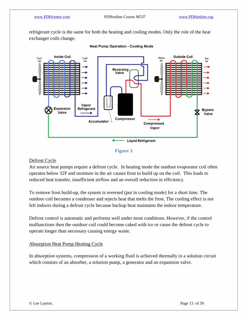
www.PDHcenter.com PDHonline Course M537 www.PDHonline.org
© Lee Layton. Page 13 of 39
refrigerant cycle is the same for both the heating and cooling modes. Only the role of the heat
exchanger coils change.
Figure 3
Defrost Cycle
Air source heat pumps require a defrost cycle. In heating mode the outdoor evaporator coil often
operates below 32F and moisture in the air causes frost to build up on the coil. This leads to
reduced heat transfer, insufficient airflow and an overall reduction in efficiency.
To remove frost build-up, the system is reversed (put in cooling mode) for a short time. The
outdoor coil becomes a condenser and rejects heat that melts the frost. The cooling effect is not
felt indoors during a defrost cycle because backup heat maintains the indoor temperature.
Defrost control is automatic and performs well under most conditions. However, if the control
malfunctions then the outdoor coil could become caked with ice or cause the defrost cycle to
operate longer than necessary causing energy waste.
Absorption Heat Pump Heating Cycle
In absorption systems, compression of a working fluid is achieved thermally in a solution circuit
which consists of an absorber, a solution pump, a generator and an expansion valve.

www.PDHcenter.com PDHonline Course M537 www.PDHonline.org
© Lee Layton. Page 14 of 39
Absorption systems require a fluid pair. The most common working pairs for absorption systems
are: water (working fluid) and lithium bromide (absorbent); and ammonia (working fluid) and
water (absorbent). Water is used as the absorbent and ammonia is the refrigerant. The refrigerant
vaporizes in the evaporator and is absorbed by the absorbent in the absorber.
Absorption heat pumps are thermally driven, which means that heat rather than mechanical
energy is supplied to drive the cycle. Absorption heat pumps for space conditioning are often
gas-fired. Absorption systems utilize the ability of liquids to absorb the vapor of the working
fluid.
A gas burner provides heat input to boil the solution, causing the release of refrigerant vapor.
The refrigerant vapor condenses, releasing its heat to the house and returns to the evaporator
where the cycle is repeated.
Heat is extracted from the heat source in the evaporator. Useful heat is given off at medium
temperature in the condenser and in the absorber. In the generator high-temperature heat is
supplied to run the process. A small amount of electricity may be needed to operate the solution
pump.
Starting at the outside coil on the right side of Figure 4, low-pressure vapor from the evaporator
is absorbed in the absorbent. This process generates heat. The solution is pumped to high
pressure and then enters the generator, where the working fluid (ammonia) is boiled off with an
external gas heat supply at a high temperature. The working fluid, which is now in a gas state
(vapor), is condensed in the condenser while the absorbent is returned to the absorber via the
expansion valve.
Figure 4

www.PDHcenter.com PDHonline Course M537 www.PDHonline.org
© Lee Layton. Page 15 of 39
Chapter 2
How VRF Systems Work
In the 1950s ductless split HVAC systems with single indoor
units and outdoor units came on the market. These ductless
products were designed as quieter, more efficient alternatives
to window units. A variation of the traditional ductless
system is a multi-split system which includes multiple indoor
units connected to a single outdoor unit. Ductless products
are fundamentally different from ducted systems in that heat
is transferred to or from the space directly by circulating
refrigerant to indoor units located near or within the
conditioned space. In contrast, conventional ducted systems
transfer heat from the space to the refrigerant by circulating
air in ducts throughout the building.
VRF systems are enhanced versions of ductless multi-split systems, permitting more indoor
units to be connected to each outdoor unit and providing additional features such as simultaneous
heating and cooling and heat recovery. Although systems vary among manufacturers, VRF
technology is usually available as heat pump or heat recovery units. Heat pumps provide either
heating or cooling. Heat recovery systems allow for simultaneous heating and cooling—which
means, for example, that one condensing unit might be connected to six indoor units, three of
which could be used to cool some areas, and three of which could be used to heat other areas, all
at the same time. VRF heat pump systems only permit either heating in all of the indoor units, or
cooling of the all the units, but not simultaneous heating and cooling. Heat recovery systems
provide simultaneous heating and cooling as well as heat recovery to reduce energy use during
the heating season.
The term variable refrigerant flow refers to the ability of the system to control the amount of
refrigerant flowing to each of the evaporators, enabling the use of many evaporators of differing
capacities and configurations, individualized comfort control, simultaneous heating and cooling
in different zones, and heat recovery from one zone to another. Most VRF condensers use
variable frequency drives to control the flow of refrigerant to the evaporators. Refrigerant flow
control lies at the heart of VRF systems and is the major technical challenge as well as the source
of many of the system’s advantages.
In most cases, two-pipe systems can be used effectively (in VRF heat pump systems) when all
the zones in the facility require cooling or all require heating during the same operating period.
Three-pipe (a heating pipe, a cooling pipe and a return pipe) systems work best when there is a
need for some of the spaces to be cooled and some of them to be heated during the same period.

www.PDHcenter.com PDHonline Course M537 www.PDHonline.org
© Lee Layton. Page 16 of 39
A VRF system uses an outdoor compressor and multiple small indoor evaporators to condition
the air only in their zones. The outdoor unit is connected through refrigerant lines to the indoor
evaporators, each individually controllable by its user. The term variable refrigerant flow refers
to the ability of the system to control the amount of refrigerant flowing to each of the
evaporators.
By operating at varying speeds, VRF systems work only at the needed rate, which means they
consume less energy than on/off systems, even if they run more frequently.
The key design element of a direct expansion system is that there is one condensing unit to one
evaporator. This means that once a condensing unit is connected to an evaporator inside the
building, providing cool air to several spaces requires either ductwork or additional condensing
units and evaporators. See Figure 5.
Figure 5
However with VRF systems, in which one condensing unit can be connected to multiple
evaporators, each individually controllable by its user. Similar to the more conventional ductless
multi-split systems, which can also connect one outdoor section to several evaporators, VRF
systems are different in one important respect - although multi-split systems, like DX systems,
turn on and off depending on whether the room to be cooled is too warm or not warm enough -

www.PDHcenter.com PDHonline Course M537 www.PDHonline.org
© Lee Layton. Page 17 of 39
VRF systems constantly modulate the amount of refrigerant being sent to each evaporator. By
operating at varying speeds, VRF units work only at the needed rate, which is how they consume
less energy than on/off systems, even if they run more frequently.
VRF systems generally include one or more air-source outdoor compressor units serving
multiple indoor fan coil refrigerant evaporator units. Water-source compressor units are also
available and can be installed indoors. See Figure 6 for a view of a typical VRF system.
Figure 6
This type of system is distinguished from small split systems that may serve a maximum of three
indoor units without variable refrigerant flow. These systems are often referred to as ductless
mini-splits, or multi-splits, which are typically applied in residential or small commercial
buildings and are not covered in this report.
The individual compressor units vary in size from 6 to 30 tons for units without heat recovery,
and 6 to 24 tons for units with heat recovery. In some cases, one or more compressor units may
be integrated into effectively one system serving a larger combined load. Fan coil unit capacity
typically ranges from 0.5 to 8.0 tons of cooling. A total of 60 or more indoor units can be served
by a single compressor unit, and the total peak capacity of the fan coil units can exceed the peak
capacity of the compressor unit, allowing for diversity in the loads.

www.PDHcenter.com PDHonline Course M537 www.PDHonline.org
© Lee Layton. Page 18 of 39
Required outside air must be delivered to the space through another mechanism. This is usually
done with a separate HVAC unit, commonly called a Dedicated Outside Air System (DOAS). In
most climates, a cooling and heating source is required that conditions the air close to the room
conditions and does not provide primary cooling or heating. These units often include energy
recovery from the exhaust air to the incoming outside air, including pre-cooling the outside air
when it is hot and pre-heating the outside air when it is cold, and may also recover energy used
to dehumidify or humidify the outside air.
Ventilation can be integrated with the VRF system in several ways. A dedicated VRF indoor unit
can be used in a ducted configuration to condition the ventilation air. A separate ventilation
system and conditioning unit can be installed using conventional technology and the VRF system
function is restricted to the recirculation air. Some VRF units have the ability to handle some
outside air and may be used accordingly. Because of humidity issues, bringing the outside air
into the room and then conditioning it with the VRF is not recommended except in dry climates
where condensation will not create moisture problems. Heat recovery ventilators can be to
reduce cooling loads on the VRF units.
The fan coil units can be mounted directly in the space with a variety of configurations in the
ceiling, walls or at the floor level. The fan coil units can also be hidden above the ceiling or other
locations, near, but not in, the conditioned space and connected to the space through short air
ducts. Fan coils condition and re-circulate air from the space. There is no central air system with
ductwork to provide the primary conditioning of the spaces, but there may be a smaller system to
provide outside air.
VRF Features
VRF provides an innovative package of energy savings features, which are described below.
The compressor unit includes two or more scroll or rotary compressors, at least one of which is
an inverter-controlled variable-speed VRF compressor. The variable-speed compressor units are
rated at significantly higher part-load efficiency than constant-speed systems.
The indoor fan coil units are connected to the compressor units with refrigerant piping, similar to
a conventional split systems. Using refrigerant to deliver heating and cooling requires less energy
because of the larger heat capacity of the refrigerant relative to air. Less mass flow is needed to
deliver the same amount of heating or cooling. The refrigerant still needs to be pushed through
the piping, and as piping runs lengthen to serve large and taller building, increasing energy will
be used at the compressor to maintain the flow of refrigerant.
www.PDHcenter.com PDHonline Course M537 www.PDHonline.org
© Lee Layton. Page 19 of 39
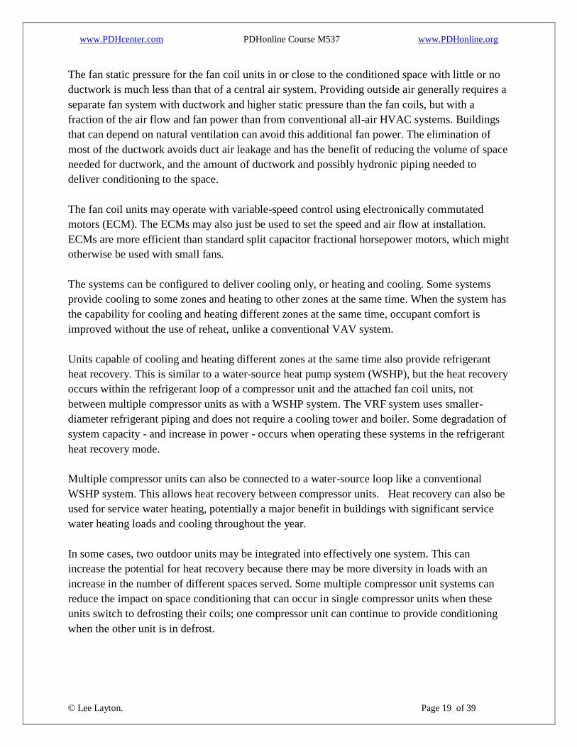
The fan static pressure for the fan coil units in or close to the conditioned space with little or no
ductwork is much less than that of a central air system. Providing outside air generally requires a
separate fan system with ductwork and higher static pressure than the fan coils, but with a
fraction of the air flow and fan power than from conventional all-air HVAC systems. Buildings
that can depend on natural ventilation can avoid this additional fan power. The elimination of
most of the ductwork avoids duct air leakage and has the benefit of reducing the volume of space
needed for ductwork, and the amount of ductwork and possibly hydronic piping needed to
deliver conditioning to the space.
The fan coil units may operate with variable-speed control using electronically commutated
motors (ECM). The ECMs may also just be used to set the speed and air flow at installation.
ECMs are more efficient than standard split capacitor fractional horsepower motors, which might
otherwise be used with small fans.
The systems can be configured to deliver cooling only, or heating and cooling. Some systems
provide cooling to some zones and heating to other zones at the same time. When the system has
the capability for cooling and heating different zones at the same time, occupant comfort is
improved without the use of reheat, unlike a conventional VAV system.
Units capable of cooling and heating different zones at the same time also provide refrigerant
heat recovery. This is similar to a water-source heat pump system (WSHP), but the heat recovery
occurs within the refrigerant loop of a compressor unit and the attached fan coil units, not
between multiple compressor units as with a WSHP system. The VRF system uses smaller-
diameter refrigerant piping and does not require a cooling tower and boiler. Some degradation of
system capacity - and increase in power - occurs when operating these systems in the refrigerant
heat recovery mode.
Multiple compressor units can also be connected to a water-source loop like a conventional
WSHP system. This allows heat recovery between compressor units. Heat recovery can also be
used for service water heating, potentially a major benefit in buildings with significant service
water heating loads and cooling throughout the year.
In some cases, two outdoor units may be integrated into effectively one system. This can
increase the potential for heat recovery because there may be more diversity in loads with an
increase in the number of different spaces served. Some multiple compressor unit systems can
reduce the impact on space conditioning that can occur in single compressor units when these
units switch to defrosting their coils; one compressor unit can continue to provide conditioning
when the other unit is in defrost.

www.PDHcenter.com PDHonline Course M537 www.PDHonline.org
© Lee Layton. Page 20 of 39
The compressor units can operate at low outdoor air temperatures. Some manufacturers report
that their units can provide up to 70% of their rated heating capacity at -7F. This can eliminate
the need for a supplemental heat source in some climate zones. In some conditions, a full backup
heat source may be needed if the outdoor temperatures fall below the operating range of the
compressors. Compressors that can perform at even lower outdoor air temperatures using dual-
stage compressors or flash injection heating are available.
VRF Configurations
As previously mentioned, VRF systems may be designed in different configurations to provide
heating and cooling of different zones at the same time and heat recovery. A two-pipe system
delivers heating or cooling to each space through one pipe to the fan coil with the second pipe
returning refrigerant to the compressor. A three-pipe system includes separate cooling and
heating lines to each indoor unit and a return line.
In both two-pipe and three-pipe systems with refrigerant heat recovery, one or more heat
recovery units are included between the compressor unit and the fan coil units. This unit controls
the flow of liquid and vapor refrigerants between the fan coil units in heating or cooling mode,
and minimizes the load on the compressor. Methods vary by manufacturers who provide their
own valves, heat exchangers, controls and other components. Figure 7 shows simplified
diagrams of two configurations with heat recovery.
Figure 7
The fan coil units are available in ductless and ducted form. Ductless fan coil units discharge and
return air directly to and from the conditioned space through the unit. These fan coil units are

www.PDHcenter.com PDHonline Course M537 www.PDHonline.org
© Lee Layton. Page 21 of 39
mounted on the wall, at the floor, or on the ceiling. Units can also be ducted from a fan coil in a
location not visible from the space with supply and return grilles in the space referred to as a
concealed unit. This can be problematic because fan coils may not be available to provide large
enough air flow to serve multiple zones, or sufficient fan power to overcome the pressure drop in
the duct system.
The fan coil units are equipped with
condenser water drains and can be used to
provide at least some dehumidification.
Small condensate pumps are required,
which need piping and wiring, typically
over occupied spaces. The noise from the
condensate pumps has been reported as a
distraction. These systems include
integrated controls to coordinate the flow of refrigerant. The systems include multiple
monitoring and control points and automated diagnostic capability. Most, if not all, VRF systems
can communicate with other equipment, such as an energy management system, through open
protocols including BACnet and LONworks. The systems can also serve as their own energy
management system for small buildings.
VRF systems may include optional refrigerant-to-water heat exchange for pre-heating service hot
water, or for providing chilled or heated water for radiant cooling and heating applications.
Water temperatures up to 160F may be possible with a supplemental booster refrigeration cycle.
The service water heating option is a good application when space cooling is needed year-round,
and there are significant service water heating loads.
Less frequently, water-source compressor units are linked by a common water loop served by a
cooling tower and heating source similar to WSHP systems. The water-loop cooling source is
typically a cooling tower; the heating source is typically a boiler; ground-source well fields,
ground or surface water, or waste heat can also be used. If a boiler is used, this becomes the
primary heat source and does not reduce heating energy usage. A cooling tower uses evaporative
cooling to pre-cool the water in the loop more efficiently than a compressor unit. The VRF
compressor unit then rejects heat to this pre-cooled water, operating more efficiently than when
rejecting heat to outside air at higher temperature. Using a ground-source well field instead of a
boiler and cooling tower provides large additional energy savings, although ground-source well
fields are typically more expensive than central plant equipment.
When multiple compressor units are connected through the water loop, heat recovery between
the compressor units can occur when some compressor units are operating primarily in cooling
BACNet is a communications protocol for building
automation and control networks.
LONworks is short for local operation network, it is a
networking platform created to address the needs of control
applications. The platform is built on a protocol created by
Echelon Corporation for networking devices over media, such
as twisted pair, power lines, fiber optics, and radio frequency.

www.PDHcenter.com PDHonline Course M537 www.PDHonline.org
© Lee Layton. Page 22 of 39
and other units are operating primarily in heating. At the same time, heat recovery can occur in
the refrigerant loop connected to each compressor unit, as described above.
Outdoor Air
Typically, VRF systems provide only space cooling and heating by recirculating air within the
space; outdoor air has to be provided separately. Fresh air can be ducted to the indoor fan coils
directly or even be introduced by natural ventilation. Typically, a separate dedicated outside air
system (DOAS) will be used. DOAS are not unique to VRF systems and are used with many
different types of systems, especially systems that do not deliver heating and cooling using air
from a central source but use water or refrigerant. This includes chilled and hot water fan coils,
WSHPs, radiant cooling and heating, and conventional split systems.
Dedicated outside air systems are often
equipped with energy recovery or heat
recovery. Energy recovery, allows sensible
and latent heat to be exchanged between the
entering outside air and the exhaust air. In humid climates, much of the energy associated with
cooling is to remove the moisture from the air through condensation.
Recovering part of this energy is done through latent energy recovery by transferring incoming
moisture to the exiting air, which was previously de-humidified. When heating, energy recovery
pre-heats (and possibly humidifies) cold entering air with exhaust air from the space, recovering
some of the energy used to heat the space. Heat recovery only systems just allow recovery of
sensible heat, which is appropriate in climates where humidity or lack of humidity is a significant
concern.
Dedicated outside air systems provide energy savings, particularly with exhaust energy recovery,
and substantial air quality benefits and DOAS units with energy recovery are incorporated in
most of the HVAC systems recommended for advanced energy efficient systems.
Control of a DOAS and coordination with the control of the VRF fan coil units can be
problematic. A DOAS should be operated on a temperature reset schedule so that it can provide a
cooling benefit when outside air temperatures allow, and cooling is needed in the space. VRF
controls may not be set up for the level of zone information needed for an effective reset based
on space conditions; a reset based on outside air temperature could be used in this case.
In some retrofit installations, existing HVAC systems have been left in place to provide outside
air and have left thermostat control in place, which results in adjustment of the outside air
temperature delivered to the space or to the fan coil unit. This will result in a lack of control
Sensible Heat is the energy contained in the dry air.
Latent Heat is the energy contained in the moisture
content of the air.

www.PDHcenter.com PDHonline Course M537 www.PDHonline.org
© Lee Layton. Page 23 of 39
coordination and possibly cycling between the existing HVAC system and the VRF system and
excessive fan energy use, particularly if the RTU is constant volume and continues to operate at
full air volume continuously to provide outside air. VRF manufacturers provide a control
interface unit that can help mitigate this problem, but it is quite expensive. Replacing the unit
with a DOAS sized to meet just the outside air requirement can still allow using the existing
ductwork with some modifications to ensure proper velocities in the space to maintain air
distribution.

www.PDHcenter.com PDHonline Course M537 www.PDHonline.org
© Lee Layton. Page 24 of 39
Chapter 3
Case Study
This case study is based on a variable refrigerant flow system trial project by the United States
General Services Administration (GSA) at the
John Joseph Moakley U.S. Courthouse in
Boston Massachusetts. An interior photo of
the John Joseph Moakley Courthouse is shown
on the right.
The John Joseph Moakley courthouse is a 10-
story building with a basement mechanical
room. The building is served by water-cooled
chillers and an ice storage system. Boilers
provide hot water for heating. The chilled
water and hot water pumps are equipped with
variable frequency drives (VFDs), and the
condenser water system is constant flow.
Space conditioning is provided by VAV air handlers with hot water reheat. The chilled water
system includes an ice storage system, which is the primary cooling source during occupied
hours. The chiller normally only runs at night to recharge the ice storage because conditions for
operating the cooling tower efficiently are better. There are 35 Air Handling Units (AHUs). Nine
of these are located on the 10th
floor; the rest in the basement.
The energy usage of the different elements of the system is not tracked. Energy usage is not sub-
metered at the separate plant and air-handler equipment level, so determining the before and after
energy impact of changes is difficult.
The GSA developed plan to replace the space cooling
and heating (but not the existing AHUs) in the east and
west wings on the 9th
and 10th
floors. VAV air-handler
unit AC26 serves the west wing of both floors and AC27
serves the east wing of both floors. AC26 provides
26,300-cfm supply air flow, and AC27 provides 27,100-cfm supply air flow, both with design
total static pressure of 5.9-in. w.g. and 50-hp fan motors.
The original plan included installing 12 water-cooled compressor units, five for the 10th
floor
with 36 indoor units, and seven for the 9th
floor, with 59 indoor units. The actual installation
included eight water-cooled VRF compressor units, four for the 10th
floor with 27 indoor units,
w.g. is water gauge and is the
pressure required to support a water column of the specified height and is measured in millimeters.

www.PDHcenter.com PDHonline Course M537 www.PDHonline.org
© Lee Layton. Page 25 of 39
and four for the 9th
floor, with 34 indoor units. The installation included only the first three
phases of a seven-phase planned project, which was not continued as a result of budget
constraints. Installation began in 2010 and was completed in 2011.
Existing terminal units were removed and were replaced with VRF fan coil units connected to
the existing ductwork and diffusers that previously connected the terminal units to the
conditioned spaces. The systems are installed with heating, cooling and heat recovery capability.
The VAV AHUs continue to provide conditioning to the areas not equipped with VRF fan coil
units, and provide outdoor ventilation to the fan coil units.
The energy benefits of this VRF retrofit as originally planned could have included reduced fan
energy, improved cooling efficiency, added heat recovery, and reduced energy for outside air
ventilation. As a result of the use of ice storage at the site, and incomplete installation of the VRF
system, these benefits are not fully realized.
Fan Energy
If fully implemented, the fan energy of the main air handlers could be reduced through several
mechanisms.
Fan power is partially driven by the static pressure, the resistance to air movement, through the
air distribution system, including the air-handler unit, into and through the ductwork, the
terminal units for VAV systems, and the diffusers that deliver air into the space. The highest
static pressure occurs on at least one pathway of ductwork and other components to the space.
Reducing air flow through the system reduces the static pressure and the fan power, if ductwork,
the fan, and other system components remain the same size. Fan power varies in direct
proportion to the quantity of air delivered by the fan when the fan speed remains constant. Fan
power is reduced even more with reduction of air flow with fans with variable frequency drives,
such as in the VAV systems at the Moakley Courthouse.
If the VRF system were fully implemented, the air flow of the central units would be reduced to
just meet outside air requirements. The static pressure experienced by the air-handler fans would
be reduced both by the reduced air flow and by the removal of the terminal units, and the static
pressure setpoint the fan is controlled to overcome, could be lowered. The fan coil unit fans
would overcome their own internal static pressure and that of the downstream ductwork and
diffusers.
In the actual installation, some of the VAV boxes remained in place and the maximum actual
static pressure at the AHUs may not have been reduced significantly by removal of terminal
units. If the terminal unit on the highest static air flow pathway were not replaced with VRF fan

www.PDHcenter.com PDHonline Course M537 www.PDHonline.org
© Lee Layton. Page 26 of 39
coils, which add no static pressure to the central fans, then central fan power was not reduced by
removal of terminal units. However, some reduction in static pressure for reduced supply air
flow through the ducts and other system components did probably occur.
Cooling and Pumping Energy
Cooling with water-cooled condenser VRF units could theoretically save energy relative to
cooling with the water-cooled chillers. Energy used for chilled-water pumping is reduced.
Condenser-water pumping and cooling tower operation continue because the VRF compressor
units are served by that same equipment. There should be an increase in associated daytime
energy use (kWh) and peak demand (kW) because the VRF runs during the occupied hours,
unlike the chillers, which normally only operate during the unoccupied hours.
The rated Integrated Energy-Efficiency Ratio (IEER) of the most common size of the VRF
condenser units installed is 17.0, or 0.71 kW/ton. The nominal cooling efficiency of the chillers
is 0.6 kW/ton. However, the chiller is producing 27F brine for ice storage, which is typically less
efficient than producing normal chilled water around 44F. With 60 feet of head, and assumed
15F delta-T, the chilled water pump would add about 0.024 kW/ton at full load, but the chilled
water pumping system is controlled by a VFD and will normally run at a fraction of that power.
Even allowing for the pumping energy, the chiller efficiency could be significantly lower when
making ice than the nominal efficiency, and still be more efficient in cooling than the VRF
system.
Ice is normally produced during unoccupied hours when demand charges are low. Because
ambient temperatures are low during these hours, the chilled water system will operate at higher
efficiency relative to operating during the day. The chillers can also operate during the off peak
hours near or at their ideal part load efficiency, because the load on the chiller is practically
constant when making ice. Only in high cooling demand periods will the chillers be forced to
operate at loads outside of the ideal part-load efficiency. The chiller operating efficiency may
even be higher than if the chillers were operating at normal chilled water temperatures during the
day. Additional energy is used with the ice storage system for pumping, and to make up losses
from the ice storage system. In any case, because of reduced demand charges, the energy cost of
the chilled water operation per unit of cooling are intended to be and probably are lower than
they would be if operating conventionally during the day.
Integrated energy-efficiency ratio (IEER) is a partial-load efficiency measure, calculated with the sum of weighting
factors applied to tested efficiencies at four part-load conditions:
(EER at 25%) * 0.125 + (EER at 50%) * 0.238 + (EER at 75%) * 0.617 + EER at 100%) * 0.02

www.PDHcenter.com PDHonline Course M537 www.PDHonline.org
© Lee Layton. Page 27 of 39
Heat Recovery
The VRF system allows refrigerant heat recovery. If there are significant periods when some
spaces served by the VRF system are in cooling and other spaces are in heating, then heat
recovery occurs. Boston experiences cold outside temperatures seasonally and because the fan
coil units are located in both the core and interior, there is opportunity for heating and cooling
and heat recovery to occur together.
Potential heat recovery is reduced relative to the plan because of the reduced number of fan coil
units installed.
Outside Air
If the project were completed, the VAV AHUs could be converted to operate solely as DOAS
units. Because the AHUs now serve areas partially served by VRF fan coils, energy savings
benefit from a DOAS type operation may be reduced relative to a full installation of VRF fan
coils. The air flow to the fan coil units is reduced to 30% of the maximum air flow that was
provided to the corresponding terminal units, reducing fan power as described above. However,
the air flow to the fan coil units will be supplied at the supply air temperature of the main
system; if a zone served by a fan coil unit calls for less cooling, even at 30% of the original
maximum air flow, some VRF fan coil units may end up switching into heating mode to provide
reheat. A VRF system with a DOAS unit does not normally need to provide any reheat, assuming
the DOAS air temperature is controlled appropriately.
Heating Energy
The AHUs and the VRF units both utilize the boilers as the primary heat source. The VRF
compressor units draw heat from the hot water loop, which the boilers replace. No heating
energy savings apart from heat recovery described above should occur. With air-cooled VRF
systems, heating is provided by the VRF compressors operating in a heat pump mode, which can
save energy relative to other heat sources.
If the original VRF plan is completed, the potential fan, cooling and heating energy recovery,
and outside air energy savings may be fully realized. If net cooling efficiency of the VRF
systems is lower than for the chiller plant, then the overall HVAC energy savings will be
diminished.
If the VAV AHUs are operating effectively as DOAS units, adding exhaust energy recovery to
these AHUs could provide additional savings. A run-around loop with coils in the exhaust air
stream, and in the return air stream, would be more feasible than adding an energy recovery
wheel. Adding an energy recovery wheel would require a lot of space, and a crane to move a
stand-alone energy recovery unit to the roof.

www.PDHcenter.com PDHonline Course M537 www.PDHonline.org
© Lee Layton. Page 28 of 39
The GSA says that estimating the total energy savings for this project is difficult because there
are no energy modeling tools that can directly capture the water-cooled VRF system operating in
heat recovery mode both on the refrigerant and water-side and interacting with the VAV systems
operating partially as DOAS units and partially for space conditioning.
This project was expected to be an excellent case study in the benefits of VRF systems.
Unfortunately, budget constraints prevented the project from being fully implemented, making
accurate measurement and verification difficult and resulted in inconclusive data.

www.PDHcenter.com PDHonline Course M537 www.PDHonline.org
© Lee Layton. Page 29 of 39
Chapter 4
VRF Applications
The primary driver in industry for energy efficiency is typically reduction of operating cost at an
affordable initial cost and reasonable payback. This chapter discusses the potential energy
savings and energy cost savings, the initial cost of VRF projects, and simple payback. Because of
the limited information available, this analysis should be used to understand the potential of VRF
technology and to help identify the types of buildings that may be good candidates for VRF
technology.
VRF systems are marketed as offering extraordinary improvements in energy efficiency,
including savings of up to 60% in HVAC energy usage compared to a range of other systems.
This is based on improved efficiency in all three areas of the HVAC system energy usage
(cooling, heating, and fans).
For cooling efficiency, Air Conditioning, Heating and Refrigeration Institute (AHRI) product
certifications include many VRF products with IEER ratings of up to 20 IEER or about 0.7
kW/ton. Cooling savings relative to conventional equipment can be estimated by examining
minimum efficiency requirements in ASHRAE Standard 90.1 2010. Where,
o Unitary AC – minimum efficiency is
from 9.6 to 11.4 IEER, depending on
cooling capacity. The VRF systems that
achieve the typical range of IEER can
save about 50% cooling energy.
o Air-cooled chiller - minimum
Integrated Part-Load Value (IPLV) is 12.5 to 12.75 IPLV; the VRF could save about
30% cooling energy.
o Water-cooled chiller – minimum IPLV ranges from 0.4 to 0.63 kW/ton. The VRF
selection will have to be at the top of its IEER range to approach these efficiencies.
Chilled and condenser-water pumps save cooling energy alone relative to water-cooled
chillers. The cost of water used in cooling towers can help offset an energy cost increase
if the VRF system operates at lower average cooling efficiency than the chilled water
plant.
For heating efficiency the AHRI product certifications include air-source VRF units with COP
values that are around 3.5. Conventional heat pumps are required to achieve 3.2 to 3.3 COP
under the same rating conditions. So, heating savings of up to 25% may be possible. Relative to
a single-zone gas furnace, boiler or VAV electric reheat, the heating savings is around 75% for
the VRF.
Integrated part-load value (IPLV) is a single-number metric
based on part-load EER, COP, or kW/ton expressing part-load
efficiency for air conditioning and heat pump equipment on
the basis of weighted operation at specific increments of load
capacities for the equipment.

www.PDHcenter.com PDHonline Course M537 www.PDHonline.org
© Lee Layton. Page 30 of 39
For fans, the indoor fan coils can be ducted or non-ducted and static pressure might range from
0.5 to 1.5 in. w.g. A portion of the fan system will still be higher to deliver ventilation air.
Conventional constant-air volume (CAV) systems may have static pressure of around 4 total
inches of static, allowing savings of up to 75%. VAV units may have even higher static
pressure, but operate at 50% or lower power most of the time in part-load fan speed operation.
VRF fans should be able to achieve significant fan savings.
Potential energy savings vary based on the HVAC baseline system to which the VRF system is
compared. Most of the available information about VRF energy savings is in comparison to
conventional HVAC systems. This is problematic because a desire to minimize energy cost is
often a major criterion in projects that consider VRF systems, and a conventional system that
uses a typical amount of energy may not be considered an option. The relevant comparison in
some projects may be to determine which high- performance alternative best fits the project and
is most cost-effective. Other energy-efficient HVAC alternatives that could be considered
include radiant systems, ground-source heat pumps, chilled beams, and high-efficiency versions
of conventional systems, such as packaged CAV and VAV, or VAV with chilled and hot water.
Conventional systems can be optimized with efficient motors, pumps, variable-speed controls,
DOAS with energy recovery, demand-controlled ventilation, and, for VAV, using a coordinated
strategy to minimize reheat. See Table 1 for a comparison of energy savings of VRF systems to
several popular alternatives.
Table 1
Energy Savings from VRF Systems
Compared to other Systems
System Type Savings
VAV, Chilled Water 34%
VAV, Packaged 45%
CAV, Packaged 48%
Heat Pump, Air Source 35%
Heat Pump, Water Source 13%
VRF manufacturers are increasingly targeting larger buildings that would typically use chilled
water systems, whether air-cooled or water-cooled, as the primary cooling source. These systems
are most often coupled with VAV air handlers. Water-cooled chillers will typically have higher
average part-load efficiency than VRF systems. However, water-cooled chiller systems also have
pumps, cooling towers and air handlers, which also consume energy. Figure 8, shows a
hypothetical comparison with system efficiency at a range of part-load conditions. This

www.PDHcenter.com PDHonline Course M537 www.PDHonline.org
© Lee Layton. Page 31 of 39
compares a VRF system with a chilled water system that includes Variable Frequency Drive
(VFD) equipped chilled water pumps, and a VAV air handling unit. Although the chiller is more
efficient than VRF system, the VRF system efficiency is higher than the combined efficiency of
the chiller plant.
Figure 8
Barriers and Enablers
While use of VRF technology is growing in the U.S. market, there remain significant barriers,
including initial costs and limited availability of incentives, uncertainty about the energy savings,
and the limited infrastructure of experienced designers and installers.
At the same time, there is momentum and support for expanding the role of VRF technology in
the U.S. Efforts are underway that directly address the identified barriers. The market expansion
is led by manufacturers with integrated approaches, including training, quality control, leadership
in development of standards, and support for development of VRF information resources and
research. Other enablers include the research underway to reduce the uncertainty about VRF
system performance, and to support energy simulation to better estimate savings and the
development of energy incentives for VRF systems from utilities and other organizations.

www.PDHcenter.com PDHonline Course M537 www.PDHonline.org
© Lee Layton. Page 32 of 39
There are obstacles for moving aggressively into implementing VRF technology. Other issues
are high initial cost, existing conditions, and uncertainty about the energy savings benefits.
Initial costs are relatively high compared to conventional alternatives. The selection approach for
VRF projects in best practices above will help to limit the project mix to those with a lower
incremental cost. For some renovations, like those needing increased heating or cooling capacity
in buildings such as historic buildings constrained for space, VRF systems may be less expensive
than conventional systems. Additional ductwork may be needed for the conventional
alternatives, while less or no ductwork is needed for the VRF option. Also, as knowledge and
skills with VRF systems spread and competition increases in each market, prices may come
down.
Enablers
Growing availability of energy incentives to offset initial cost
o Utility incentives are beginning to be applied to VRF systems.
o The manufacturers are pushing to expand the knowledge base and capability of
designers and installers. This will likely increase competition and reduce the
uncertainty about the technology and potentially reduce prices as bids can get
tighter.
Research and certification
o Research is underway to develop methods to verify savings, including modeling
tools, and to resolve doubts about the field performance versus the AHRI-tested
performance. As described above, EPRI and others are engaged in lab testing,
field testing and simulation software development, and some utilities have begun
field test pilots on using energy simulation to verify savings. Development of this
information will create more certainty about the savings, and encourage growth of
incentive programs and investment in projects.
o AHRI testing protocol for certification of VRF heat recovery operating efficiency
is also in development; currently the performance in heat recovery mode is not
certified.
Education and training
o The manufacturers have an established and expanding training program for
suppliers, designers, and installers apparent by searching their websites and the
broader web for training opportunities.
o The ASHRAE Handbook, HVAC Systems and Equipment includes VRF systems.
Advantages and Disadvantages

www.PDHcenter.com PDHonline Course M537 www.PDHonline.org
© Lee Layton. Page 33 of 39
VRF systems offer advantages other than energy savings, including ease of installation,
integrated controls, and comfort. There are also limitations, including the lack of economizers,
concerns about refrigerant and the proprietary nature of the VRF systems. There is also
uncertainty about energy savings.
Initial costs for VRF systems in new building are generally significantly higher for VRF than for
conventional systems. Costs may be more comparable to other high performance HVAC
systems. Greater variation in costs caused by different building characteristics is found in the
retrofit market and ranges from VRF systems being less expensive to prohibitively more
expensive than other choices.
VRF systems are innovative, although not unique, in a number of features. The major energy
savings potential comes from the following:
Variable-speed air-cooled compressors (or at least some compressor elements) providing
high part- load cooling and heating efficiency;
Reduced fan energy caused by low static pressure and elimination of ductwork for space
cooling and heating reduces fan energy; smaller ductwork for delivery of outside air will
still be required in most cases;
Refrigerant, rather than water or air, requires less energy to move the heat transfer fluid;
Some units are capable of heating and cooling at the same time to different zones without
reheat, and providing heat recovery between zones in heating and cooling at the same
time; and
Common use of dedicated outside air systems with energy recovery.
Because VRF systems are less intrusive than many other HVAC system options, they can be of
particular benefit to historic and other older buildings. These buildings may have no cooling, or
inadequate cooling and heating capacity, inefficient and poorly operating HVAC systems, space
constraints preventing addition of or modification to ductwork, and, in the case of historic
buildings, restrictions on building changes that disrupt the appearance of the building. Adding
cooling will probably increase cooling energy usage and peak demand (kW), although this may
be offset entirely by fan and heating energy savings.
Listed below are some of the advantages and disadvantages of VRF systems.
Advantages
Installation. VRF system components are modular, small and lightweight compared to
conventional HVAC system components. They are typically installed without the use of a
crane, saving substantially on installation cost. The unit modularity supports building a

www.PDHcenter.com PDHonline Course M537 www.PDHonline.org
© Lee Layton. Page 34 of 39
system over time to serve floors as a building is occupied. The low weight can reduce the
need for structural reinforcement to support more massive equipment. The compressor
units are typically installed outdoors and do not need a machine room or mechanical
penthouse.
Controls. VRF systems incorporate sophisticated controls and automation; control of the
complex refrigerant system requires this. Manufacturers highlight the many control
points allowing careful monitoring and easy troubleshooting, including automatic
diagnostics and communication of issues to maintain. A control system is set up to
communicate among all components and can operate as an energy management system
within the network of systems. The control system can network with the rest of the
building with open protocols such as BACnet and LONworks. Providing a comparable
level of control with conventional equipment would add additional cost to those systems.
The controls also allow rapid startup and configuration, and limited commissioning is
required for warranty; additional commissioning is required to verify smooth control
when switching between heating and cooling. As an option (that adds significant
expense), the refrigerant flow to each fan coil unit can be automatically measured,
allowing the energy usage of the system to be allocated to each tenant.
Comfort. Fan coil units can be sized to serve small spaces with independent temperature
control, such as individual private offices. This adds cost relative to sizing units to serve
larger combined zones, but can improve comfort. With capability to provide heating or
cooling and modulation of the compressor, a narrow temperature range can be
maintained. Anecdotal information, and results of one informal field study, indicate that
attention needs to be paid to ensure that controls are working to maintain stable
temperature control without alternating heating and cooling. Commissioning of zone
temperature control is recommended.
Space Requirements for Delivery of Heating and Cooling. Transferring heat through
refrigerant piping requires a lot less space than ductwork. This makes VRF systems well
suited to retrofits, particularly historic buildings that may not have any ductwork or
cooling. However, if outside air requirements are not met by natural ventilation already,
then ductwork of sufficient size to provide code-required ventilation will need to be
added. In new buildings, the low space requirement can result in reduced floor-to-floor
height, providing initial cost savings.
Maintenance. Regular maintenance of VRF systems consists of changing filters and
cleaning coils for the fan coil units. This level of maintenance is not substantially
different than for other zonal systems, such as conventional watersource fan coils and
split systems. Less maintenance is required for conventional rooftop equipment.

www.PDHcenter.com PDHonline Course M537 www.PDHonline.org
© Lee Layton. Page 35 of 39
Maintenance of the compressor unit is minimal, and there will be significant maintenance
savings for this part of the system compared to chilled water and hot water plant
equipment.
Disadvantages
Lack of Economizer. Because there is no ductwork to deliver heating and cooling, there
is no air-side economizer, and because the system is refrigerant-based and not water-
based, there is not an option for a water-side economizer. With a DOAS sized just for the
required amount of outside air, a limited air economizer is available. A full or partial air-
side economizer is an option available with a DOAS unit when sized accordingly. Some
manufacturers offer a full air-side economizer option with a DOAS requiring full-sized
ductwork. However, some manufacturers argue against adding an economizer because
they think it will reduce the amount of heat recovery. In some climate settings,
economizer energy savings not captured with the VRF system will partially or even
completely eliminate the net energy savings for cooling that might otherwise be possible
with the VRF system. In the mild climate of Salem, Oregon, the cooling energy savings
for an economizer is 29%, which accounts for over 11% of total HVAC energy usage.
Together, VRF cooling, fan and heating energy savings can offset the lack of an
economizer, and still result in significant net savings. Economizers are required by most
energy codes and standards, but VRF systems may be exempt in some codes and
standards. Standards and codes typically have size thresholds, below which a unit does
not need to meet the economizer requirements, and many VRF fan coils fall below those
limits. Some jurisdictions treat the compressor unit capacity as the system capacity. In
these cases, the system may qualify for an exception based on the compressor unit
cooling efficiency exceeding the standard minimum efficiency requirement by a
percentage or other measure. Washington state code allows a VRF exception for
economizers when the VRF system has refrigerant heat recovery and includes a DOAS
system with exhaust heat recovery.
Refrigerant. Concerns have been raised about health, expense, and environmental
impacts from refrigerant leaks. The grocery store industry has experienced major
problems with leakage in refrigeration systems leading to a movement away from the
delivery of cooling with refrigerant. Concern exists about possible leaks from flare
fittings provided by the manufacturer, and some installers use braised connections.
Finding leaks is difficult. In response to these concerns, manufacturers maintain that
leakage can be minimized with proper training, which the manufacturers require and
provide, coupled with installer experience. The refrigerants are nontoxic, and no health
problems have been reported from these installations. Use of continuous tubing for the
refrigerant lines can also limit joints. Properly installed, flare fittings do not leak, and

www.PDHcenter.com PDHonline Course M537 www.PDHonline.org
© Lee Layton. Page 36 of 39
allow the system to remain easier to reconfigure. Some manufacturers require heightened
piping pressure tests for an extended period. The grocery store leakage issue may be
related to the use of aftermarket components that may not be compatible with existing
installations, a variety of installers without coordinated training, and lack of quality
control involving the suppliers and manufacturers, which is not the case with VRF
systems. Further research may be needed to resolve the degree to which leaks occur,
determine if that level of leakage is a problem and identify how to prevent further
leakage. With long refrigerant lines passing through small spaces, the refrigerant-to-
space volume could exceed the ASHRAE Standard 15 limit, triggering requirements for
refrigerant mechanical rooms under ASHRAE Standard 15. A designer reported running
into this problem with a small electrical room. The solution developed for that project
was to connect the space to other spaces with transfer grilles and fire smoke dampers,
which added cost. The designer shared that a better solution being applied is to use
solenoid valves to limit the quantity of refrigerant that could be released into the space.
Another approach is to increase the number of VRF systems to reduce the amount of
refrigerant in each system.
Proprietary systems. Components are not compatible across manufacturers, and there is
no secondary market for components. Building owners are a captive customer once the
system is installed, exposing them to a lack of price competition for replacement parts
and future building retrofit projects. A benefit of this can be maintaining an integrated
system with coordinated control and quality assurance. Manufacturers are often involved
in the design of VRF systems. Structuring bid documents for open bidding of VRF
systems is difficult because of manufacturer involvement in the final design.
Target Market for VRF Systems
For existing buildings, facilities managers should focus on buildings determined to have an
minimal estimated incremental cost (e.g. less than $4.00 per square foot) for VRF relative to the
alternatives, and with energy usage and energy costs higher than average buildings. Existing
buildings to target include one or more characteristics:
Need for HVAC upgrades or cooling expansion with limited room for ductwork changes
Climates with significant heating loads
Buildings with electric reheat, supplemental heat, or primary heating
Within the range of 5,000 to 100,000 square feet
Buildings with enclosed spaces that would benefit from independent temperature control.
For new buildings, targeting larger scale high-performance buildings is recommended.
Opportunity to reduce floor to floor height or increase occupied floor area using VRF rather than

www.PDHcenter.com PDHonline Course M537 www.PDHonline.org
© Lee Layton. Page 37 of 39
other HVAC alternatives should also be a focus. The size and climate characteristics identified
for existing buildings also apply to new buildings.
Buildings switching from gas heat to VRF systems offer large energy savings, but because of the
price differential between electricity and gas, the utility bill savings will be greater when
switching to VRF systems from VAV systems with electric resistance reheat or other electric
resistance heating systems. This is especially true in buildings where switching to VRF systems
would increase peak electricity demand.
Life-cycle costs, including operating costs other than energy (such as maintenance and
replacement costs of equipment), are also important in addition to initial cost. VRF systems are
distributed systems and each fan coil unit requires maintenance, which includes filter changes,
cleaning of condensate removal systems, replacement of fan motors, and replacement of fan
coils. Other distributed systems, such as conventional fan coils, water-source heat pumps
(WSHP), and split systems, have similar maintenance requirements. Because of the single
compressor unit serving many zones, compressor unit maintenance and replacement is similar to
other VAV and CAV systems. CAV systems often have more compressor units to serve a similar
area than a VRF system. Air-cooled VRF systems do not have any central plant equipment to
maintain or replace, and do not require a building operator, which may be required for larger
buildings with a central plant.
The building portfolio energy savings potential for new buildings is less than for existing
buildings because the building floor area added each year is a small fraction of the existing
building floor area. Some older buildings provide a better payback than is likely achievable with
new buildings using VRF. This is because the energy savings potential is not as great as with
some older, more energy-intensive buildings. The incremental initial cost of a new VRF system
versus a conventional system can be greater than the incremental cost of alternative system
retrofits selected where VRF’s advantages (such as reduced space relative to ducted systems) are
available. Relative to other energy-efficient HVAC systems, including high performance
conventional systems and newer systems such as radiant panels, VRF systems may offer
comparable or even lower initial costs and similar or lower energy usage alternatives.
VRF systems may include about twice the refrigerant of comparable roof-top units, depending on
the size of the building area served. Concern has been raised about added cost associated with
replacement of this refrigerant, and with refrigerant leaks.

www.PDHcenter.com PDHonline Course M537 www.PDHonline.org
© Lee Layton. Page 38 of 39
Summary
Variable Refrigerant Flow system technology has successfully demonstrated itself outside the
U.S., where it dominates the HVAC market in many countries. The U.S. market has been slower
to respond, but interest is growing. The systems offer energy saving, comfort control, flexibility,
and ease of installation in existing buildings.
Reasonable estimates for HVAC energy cost savings are around 30% for VRF as an alternative
to existing systems across a broad range of buildings, system types and climates. The
incremental costs of using VRF systems are relatively high, and opportunity for a reasonable
payback is limited for the average or less than average building energy usage.
VRF should be targeted at existing buildings with high energy bills, need for HVAC upgrades or
cooling expansion with limited room for ductwork changes, climates with significant heating
loads, particularly where VRF can replace VAV systems with electric reheat or other electric
heat, and buildings with multiple spaces that would benefit from independent temperature
control. New buildings to target include projects with a high-performance design objective and
budget to support it, buildings that can take advantage of the potential to reduce floor-to-floor
height, and the avoidance of more expensive controls and monitoring that may be included with
VRF systems.
VRF systems are most cost-effective when matched with applications and climates that offer the
best value given the typically higher initial cost of the systems. The items to consider include
operating costs, project type, building type, building size, and climate.
High Energy and Other Operating Costs
Energy usage higher than average for other similarly situated buildings.
Opportunity for conversion from VAV with electric reheat or buildings with other
electric resistance heat.
Large maintenance and replacement costs from failing equipment, or other operating
costs, such as for water usage that could be reduced or avoided by switching to a new
system.
Project Type
Retrofit projects, particularly where cooling capability needs to be added or increased, or
where there is no or inadequate ductwork and space to add ductwork is constrained. Even
if there is room for ductwork, installing refrigerant lines may be less expensive.
Retrofits with existing ductwork may be suitable for adding a DOAS without needing to
add ductwork.
Buildings with fan systems working against unusually high static pressure.

www.PDHcenter.com PDHonline Course M537 www.PDHonline.org
© Lee Layton. Page 39 of 39
Historic buildings are particularly good candidates, if upgrading or replacing the existing
systems with conventional systems would cause substantial disturbance in the building.
Owner-occupied buildings, where owner can institute major changes.
Building Type
Buildings with small, separated areas can take full advantage of the zonal control capability
of the fan units. This includes,
Office buildings with a significant number of enclosed offices, conference rooms, and
other separated spaces
Schools
Lodging
Multi-family
Healthcare
Retail community shopping center and possibly small stores in malls.
Building Size
Projects under 5,000 square feet may be less suitable because there are substantially less
expensive alternatives. Above 100,000 square feet other alternatives may be more cost
effective.
Large projects that traditionally have had a chilled and hot water plant serving large VAV
air handlers.
Weaker, but still potentially viable VRF candidates include Large open spaces, such as
big box retail, assembly halls, gymnasiums, and warehouses
Climate
Climates with more extreme weather will generate the most energy savings.
Colder climates offer better opportunities for heat recovery, especially if there is a core
with constant cooling requirements.
Colder climates also result in large heating energy savings when converting to VRF from
VAV with electric reheat or electric resistance primary or supplemental heat.
Targeted VRF projects can provide a reasonable energy cost savings and simple payback. Higher
maintenance, repair and replacement costs relative to some other system alternatives can offset
much of the energy cost savings, and these costs should be evaluated when deciding whether or
not to use VRF systems. VRF systems should be compared with other high efficiency HVAC
alternatives during early design, and between operating buildings with different HVAC systems.
Copyright © 2016 Lee Layton. All Rights Reserved.
+++