VARIABLE REACTION ORDER FOR KINETIC MODELING OF OIL SHALE PYROLYSIS OS Al-AYED
13
Oil Shale, 2011, Vol. 28, No. 2, pp. 296–308 ISSN 0208-189X doi: 10.3176/oil.2011.2.04 © 2011 Estonian Academy Publishers VARIABLE REACTION ORDER FOR KINETIC MODELING OF OIL SHALE PYROLYSIS O. S. Al-AYED * Al-Balqa Applied University Faculty of Engineering Technology Department of Chemical Engineering P.O. Box 15008 Marka 11134. Jordan This work investigates kinetics of El-Lajjun oil shale pyrolysis. The kinetic data obtained from TG/DGA curves at heating rates 1, 3, 5, 10 and 30 °Cmin –1 to a final pyrolysis temperature 550 °C were employed assuming their second-order kinetics to determine apparent activation energy, 99– 141.4 kJ/mol and frequency factor, 1.89·10 7 to 1.71·10 11 , for each heating rate using the Coats & Redfern method. The obtained values of apparent activation energies and frequency factor were modified through an equation to 112–179 kJ/mol and 3.95·10 7 –3.66·10 13 , respectively, to fit the developed kinetic equation. In this study, kinetic modeling of the pyrolysis process was performed using a newly developed variable reaction order. The variable reaction order was inferred directly from the experimental data and correlated with heating rate, h, (°Cmin –1 ), rate of conversion, dx dt and a constant equal with 8.314 (°C). The range of generated values of the variable reaction order varied between 1.99 and 1.85. Conversion of a sample was calculated basing on initial and final weight of the sample at the end of run. A satisfactory fit of the experimental data was obtained using the equation developed for a variable reaction order. Introduction Oil shale is defined as a sedimentary rock of various origins containing organic matter that, when heated, transforms into solid coke, liquid, and gaseous hydrocarbon compounds. Much work was done on pyrolysis of oil shales and their pyrolysis kinetics by thermogravimetric analysis (TGA). Different kinetic models, such as Arrhenius, Coats & Redfern, Horowitz & * Corresponding author: e-mail [email protected]
Transcript of VARIABLE REACTION ORDER FOR KINETIC MODELING OF OIL SHALE PYROLYSIS OS Al-AYED
Oil Shale, 2011, Vol. 28, No. 2, pp. 296–308 ISSN 0208-189X doi: 10.3176/oil.2011.2.04 © 2011 Estonian Academy Publishers
VARIABLE REACTION ORDER FOR KINETIC MODELING OF OIL SHALE PYROLYSIS
O. S. Al-AYED* Al-Balqa Applied University Faculty of Engineering Technology Department of Chemical Engineering P.O. Box 15008 Marka 11134. Jordan
This work investigates kinetics of El-Lajjun oil shale pyrolysis. The kinetic data obtained from TG/DGA curves at heating rates 1, 3, 5, 10 and 30 °Cmin–1 to a final pyrolysis temperature 550 °C were employed assuming their second-order kinetics to determine apparent activation energy, 99–141.4 kJ/mol and frequency factor, 1.89·107 to 1.71·1011, for each heating rate using the Coats & Redfern method. The obtained values of apparent activation energies and frequency factor were modified through an equation to 112–179 kJ/mol and 3.95·107–3.66·1013, respectively, to fit the developed kinetic equation. In this study, kinetic modeling of the pyrolysis process was performed using a newly developed variable reaction order. The variable reaction order was inferred directly from the experimental data and correlated with heating rate,
h, (°Cmin–1), rate of conversion, dxdt
and a constant equal with 8.314 (°C).
The range of generated values of the variable reaction order varied between 1.99 and 1.85. Conversion of a sample was calculated basing on initial and final weight of the sample at the end of run. A satisfactory fit of the experimental data was obtained using the equation developed for a variable reaction order.
Introduction
Oil shale is defined as a sedimentary rock of various origins containing organic matter that, when heated, transforms into solid coke, liquid, and gaseous hydrocarbon compounds. Much work was done on pyrolysis of oil shales and their pyrolysis kinetics by thermogravimetric analysis (TGA). Different kinetic models, such as Arrhenius, Coats & Redfern, Horowitz &
* Corresponding author: e-mail [email protected]
Variable Reaction Order for Kinetic Modeling of Oil Shale Pyrolysis
297
Metzger, and Ingraham & Marrier et al, were used to analyze thermo-gravimetric data obtained [1].
Campbell et al. [2] studied the rate of evolution of CH4, H2, CO, CO2, and C2, C3 hydrocarbons during pyrolysis of Colorado oil shale at varying linear heating rates from 0.5 to 4.0 °Cmin–1. More of hydrogen release was reported at lower heating rates. Methane was formed and released at tem-perature slightly lower than 350 °C reaching a maximum value at 445 °C. Rate of methane release increased with a decrease in heating rate. Ethane and ethene (C2) production increased to a maximum value at 450 °C and stopped at slightly higher than 550 °C. C3 (propane and propene) production was found to occur at 450 °C, and their formation stopped at 525 °C. Oil release profile was closely corresponding to that observed for C1 and C2 profiles.
The decomposition of the oil shale involves a large number of reactions in parallel and in series, whilst TGA measures the overall weight loss due to these reactions. A combined study [3] using TGA, diffuse reflectance infra-red Fourier transform spectroscopy (DRIFTS), and X-ray diffraction (XRD) resulted in a better insight to oil shale reactions. TGA provides general information on the overall reaction kinetics rather the individual reactions.
Li and Yue studied the pyrolysis kinetics of different Chinese oil shale samples at a constant heating rate of 5 °Cmin–1 [4]. The TGA data obtained were used to develop a kinetic model which assumed 11 first-order parallel reactions with different activation energies and frequency factors. The calculated fractional conversion of each reaction is a complex function of activation energy. At pyrolysis reactions with low activation energies, the pyrolysates of oil shale resulted mainly from the rupture of weak chemical bonds, probably the rupture of weak cross-linked bonds such as C–O, C–S bonds [5, 6], etc. and the rupture of branched functional groups in the kerogen high-molecular structure. Rupture energy of these weak bonds is low which commensurates to that of formation of gaseous products such as H2O, CO2, H2S, H2 and light hydrocarbons. The medium values of activation energy are associated with break-up of the side chains in β-position of aromatics, decomposition of normal alkanes with large molecular weight, Diels-Alder cyclization reaction and the rupture of alicyclic hydrocarbons. This corresponds to pyrolysis temperature between 420–480 °C. On the other hand, pyrolysis reactions with high apparent activation energies are mainly the aromatization of alicyclic compounds, dehydrogenation and combination of aromatic rings, rupture of heterocyclic compounds. As it is clear from the discussion above, kerogen decomposition to produce shale oil and gases is a continuous process consisting of several parallel, series, simultaneous and complex reactions. Since heating rate affects the distribu-tion of the pyrolysis products, the values of activation energy must also differ and the reaction order has to vary as well. It is possible that the varia-tion of activation energy values is associated with decomposition mechanism and, consequently, it is implicitly embedded in variation of reaction order.
O. S. Al-Ayed
298
Some researchers tested six different proposed methods to simulate pyrolysis of Spanish oil shales and calculated the values of apparent activation energy [7]. They found that the best possibility to estimate apparent activation energy of oil shale pyrolysis is a differential method followed by its integral form. In addition, these authors, basing on their findings, advocated that activation energy, frequency factor, and reaction order do not have any clear interpretation when related to chemical reactions in oil shale.
Thakur and Nattall combined isothermal and non-isothermal thermo-gravimetric analysis to study thermal decomposition of oil shale [8]. They reported that the decomposition involves two consecutive first-order reac-tions with bitumen as an intermediate. Other researchers used pseudo-first order overall reaction order in their kinetic analysis [9]. Turkish oil shale was studied by TGA at non-isothermal conditions under argon and first-order reaction kinetics was found to fit kinetic data [10]. Some other Turkish oil shales were pyrolysed using thermogravimetric analysis and reaction orders were found to vary between 1.45 and 1.73 to fit pyrolysis kinetics [11]. Qing and co-workers used the first-order kinetics in their study on pyrolysis of Huadian oil shale since it resulted in best fit of experimental data [12]. Some investigators modeled kinetics of El-Lajjun oil shale pyrolysis using first-order reaction kinetics [13, 14] while others found the second-order model to be more suitable [15]. Solid-state reaction, i.e. that of oil shale pyrolysis is generally not an elementary reaction, in which the reaction model varies with temperature, and the pyrolysis involves several steps with different activation energies [16–17]. The rate of Spanish oil shale decomposition was suitably described by an overall first order kinetics [18].
Several researchers advocated that since oil shale pyrolysis is a complicated process with multiple reaction mechanisms, reaction order, n, to be of the order 1 or 2 in the equation f(x) = (1–x)n, is not suitable to describe the overall pyrolysis reaction [17, 19]. Sestak-Berggren suggested a complex equation for oil shale pyrolysis mechanism [19]:
( ) (1 ) ln(1 ) ,m n pf x x x x = − − − (1)
where m, n, and p are constants, their derivatives implying different reaction mechanisms, in which the first term, xm, represents diffusion mechanism, the second term in Eq. (1) describes interface mechanism, and finally, the square bracketed member expresses the actual mechanism of oil shale decomposi-tion, x is conversion at the end of run. In the present case, the diffusion stage is practically absent in TG experiments since fine particle size is used; as a result, m is assumed to be zero. On the other hand, the combined oil shale decomposition and interface mechanisms are assumed to be of the form:
( ) (1 ) .nf x x= − (2)
Changing reaction order was suggested to be associated with changing reaction mechanism [20]. No doubt, reaction of oil shale kerogen decom-

Variable Reaction Order for Kinetic Modeling of Oil Shale Pyrolysis
299
position is a multiple system of reactions. Pyrolysis of oil shale is a complex process involving multiple mechanisms at all stages of product evolutions and hydrocarbon generation processes. Higher reaction order is a measure of the complexity and multiplicity of the mechanism. Several researchers have studied decomposition kinetics of oil shale pyrolysis; most of them have used the first-order reaction kinetics to model isothermal and non-isothermal kinetic data [21–25]. Integral and differential methods have been used to model El-Lajjun oil shale pyrolysis [14–15].
In this work, a mathematical formula was developed for reaction order as a variable quantity. The variable reaction order is based on conversion rate, heating rate and a constant. The developed equation for the reaction order n is employed in Eq. (2) to model the rate of conversion of oil shale decom-position during pyrolysis using the TG/DGA data.
Kinetics of oil shale pyrolysis can be described by the equations
d ( ),dx kf xt
= (3)
0d exp (1 ) ,d
nx Ek xt RT
− = −
(4)
0
0
( ) ,( )
t
f
w wxw w
−=−
(5)
where w0 – initial weight of sample, wt – sample weight at time t, wf – sample weight measured at the end of run.
The apparent activation energy in Eq. (4) is determined using the Coats & Redfern method according to the following final form of the general equation [26]:
02
2ln ln 1 .(1 )x k R RT E
hE E RTT x = − − −
(6)
Experimental procedure
Oil shale sample was obtained from the El-Lajjun mine area. The general characteristics of the studied sample are given in Table 1. The selected size fraction of raw oil shale was 100–210 µm to avoid the effect of mass and/or heat transfer on the pyrolysis process. The sample was placed in a desiccator overnight to remove moisture before the pyrolysis study. About 17–20 mg of sample was used in runs. The air in the pyrolysis unit was flushed with nitrogen before performing the analysis. Heating rates of 1, 3, 5, 10, and 30 °Cmin–1 were tried for data collection. Each sample was heated to 550 °C and the weight loss vs. temperature was recorded for each of the five heating
O. S. Al-Ayed
300
rates. Three runs were repeated for each heating rate with relative standard deviation of less that 5% and the average values of TGA curves are reported.
The TGA/DG data were obtained from experiment runs conducted in Q 500 Thermo-gravimetric analyzer. The Q 500 equipment specifications are: temperature range – ambient to 1000 °C, weighing balance capacity – 1.0 g with 0.1 µg sensitivity; temperature precision is 0.1 °C and heating rate range 0.1–100 °Cmin–1. Nitrogen gas carrier was used at a flow rate of 100 cm3min–1.
Table 1. Characteristic analysis of oil shale samples
Component Wt. % Moisture content 1.21 Total water 2.4 Total oil 12.8 Gas loss 3.4 Spent shale 81.3 Total sulfur 2.29 Total carbon 17.28 Total organic carbon 11.42 Hydrogen 1.76 CaCO3 46.31 Calorific value, kJ/kg 5487
Results and discussion
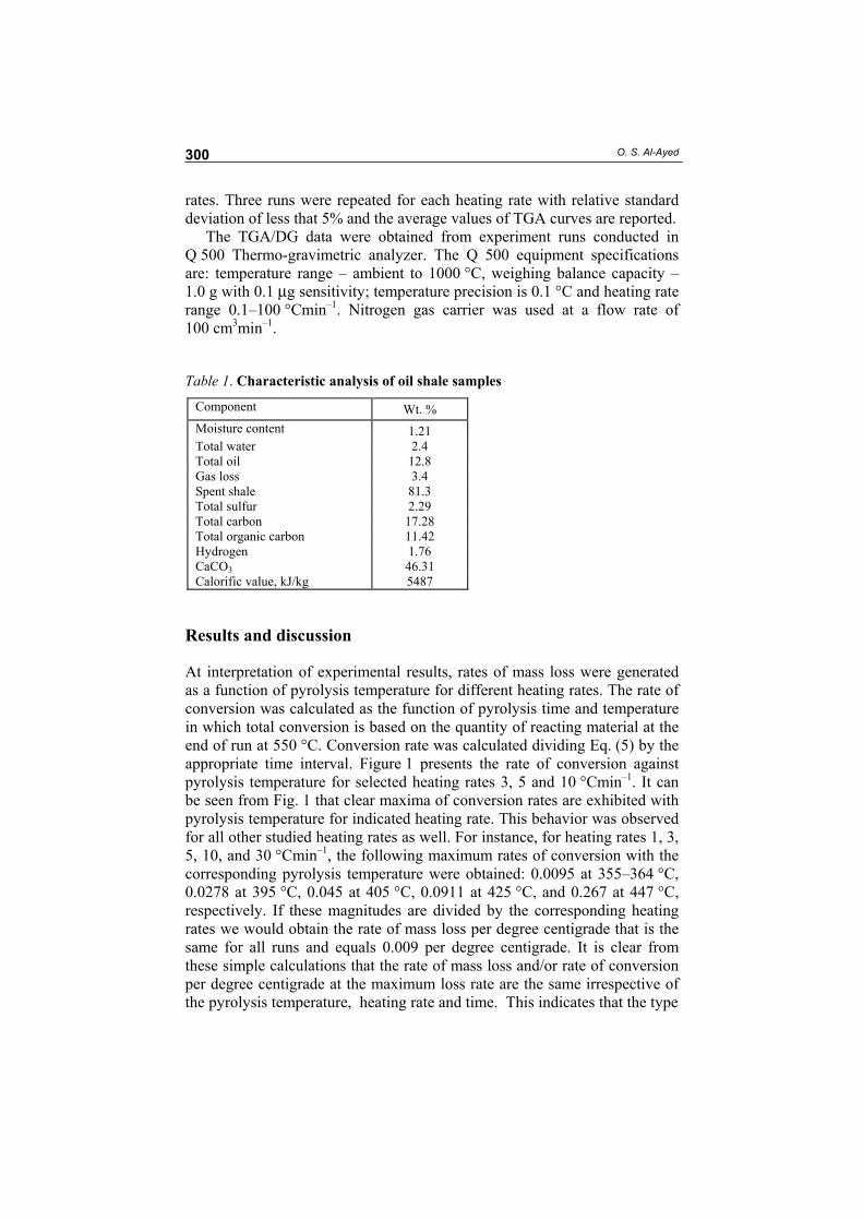
At interpretation of experimental results, rates of mass loss were generated as a function of pyrolysis temperature for different heating rates. The rate of conversion was calculated as the function of pyrolysis time and temperature in which total conversion is based on the quantity of reacting material at the end of run at 550 °C. Conversion rate was calculated dividing Eq. (5) by the appropriate time interval. Figure 1 presents the rate of conversion against pyrolysis temperature for selected heating rates 3, 5 and 10 °Cmin–1. It can be seen from Fig. 1 that clear maxima of conversion rates are exhibited with pyrolysis temperature for indicated heating rate. This behavior was observed for all other studied heating rates as well. For instance, for heating rates 1, 3, 5, 10, and 30 °Cmin–1, the following maximum rates of conversion with the corresponding pyrolysis temperature were obtained: 0.0095 at 355–364 °C, 0.0278 at 395 °C, 0.045 at 405 °C, 0.0911 at 425 °C, and 0.267 at 447 °C, respectively. If these magnitudes are divided by the corresponding heating rates we would obtain the rate of mass loss per degree centigrade that is the same for all runs and equals 0.009 per degree centigrade. It is clear from these simple calculations that the rate of mass loss and/or rate of conversion per degree centigrade at the maximum loss rate are the same irrespective of the pyrolysis temperature, heating rate and time. This indicates that the type
Variable Reaction Order for Kinetic Modeling of Oil Shale Pyrolysis
301
Fig. 1. Experimental conversion rate calculated for different heating rates.
of chemical (pyrolysis) reactions taking place is the same and they depend on oil shale properties rather than reaction variables and conditions. Inspecting TGA curves further, it can be observed that rate of mass loss or
transformation rate ddxt
increases with increasing heating rate. This pro-
portionality relationship is reflected on the magnitude of the variable reac-tion order. According to Eq. (12), the heating rate appears in denominator
while ddxt
in numerator. The magnitude of variable reaction order kept
fluctuating between 1.99 and 1.85 for all runs. As a result, the impact of heating rate on the rate of mass transformation in the present work was neutralized by the increase in the rate of conversion.
Variation of calculated variable reaction order with pyrolysis temperature and heating rate is depicted in Fig. 2. It is clear from the figure that the value of variable order passes through a minimum value with pyrolysis tempera-ture at location proportional to heating rate. For instance, at heating rate 1 °Cmin–1, the minimum variable order calculated for the temperature range 370–380 °C is 1.85, the same order value was calculated also for heating rates 3, 5, 10 and 30 °Cmin–1, at 386, 405, 420 and 450 °C, respectively. On the other hand, the initial and final calculated values of variable order were 1.99 to 1.97 which approach to 2. It was suggested [19] that reaction order is a firm indicator of reaction mechanism; the shape of Fig. 2 supports the importance of the fact that oil shale reactions differ from normal chemical complex parallel, series, and simultaneous reactions. The continuously changing values of reaction order with pyrolysis temperature are indicative of the change in the reaction mechanism. Changing reaction order could be a result of reactions that are taking place due to instability of the products, or secondary reactions, change of apparent activation energy, effect of varying of pre-exponential factor which is an implicit function of apparent activation energy in such a complex system.
Pyrolysis temperature, °C

O. S. Al-Ayed
302
Fig 2. Variation of reaction order according to Eq. (12) at different heating rates.
Data obtained from TGA curves were employed to predict the apparent
activation energy, E, according to the Coats & Redfern method [26]. The mathematical manipulation discussed in earlier works [14] was employed to estimate the apparent activation energy of the pyrolysis process. Assumption about the second-order reaction kinetics led to plotting the quantity
2ln(1 )x
T x
−
against inverse of pyrolysis temperature for estimating apparent
activation energy. The determined value of apparent activation energies and the corresponding frequency factors, k0, at heating rates 1, 3, 5, 10 and 30 °Cmin–1 calculated according to the Coats & Redfern method are given in Table 2. As reported in Table 2, the apparent activation energy increases with increasing heating rate. Estimated values of apparent activation energies were found to be within the range 99–141.5 kJ/mol. These values imply that heating rate influences the estimation of apparent activation energy. The values of frequency factor varied from 1.89·107 to 1.71·1011 min–1. The pre-exponential factor and apparent activation energy are related to each other as follows:
2
0ln 0.199 2.967, R = 0.995.k E= − (7)
Table 2. Values of apparent and modified apparent activation energies and corresponding pre-exponential factors values at different heating rates
Heating rate, h, °C/min
Apparent activation energy, E,
kJ/mol
Pre-exponential
factor, ko
Modified apparent
activation energy, Em
Modified frequency,
(ko)m
Apparent activation energy, Eq. (11)
Frequency factor, from
Eq. (11)
1 99 1.89E+07 110 3.95E07 112 4.9E+7 3 111 2.31E+08 129.6 2.16E+9 124 8.24E+8 5 114.5 5.00E+08 135.2 7.43E+9 136 8.41E+9 10 125 3.25E+09 148.6 4.30E+10 148 9.82E+10 30 141.4 1.71E+11 179.2 3.66E+13 175 1.89E+13
Pyrolysis temperature, °C
Var
iabl
e re
actio
n or
der,
n
Variable Reaction Order for Kinetic Modeling of Oil Shale Pyrolysis
303
Equation (7) is obtained plotting the apparent activation energy versus natural logarithm of frequency factor as given in Table 2. The actual apparent activation energy and frequency factor values employed in the present work are not those obtained by the Coats & Redfern method but modified according to the following equations:
21.629 51.26, R = 0.928,m CoatsE E= − (8)
20 0ln( ) 1.598ln( ) 9.279, R = 0.93.m Coatsk k= − (9)
Equations (8) and (9) were obtained plotting apparent activation energy and frequency factor estimated from equations (6) and (11), respectively. The need for using different values for apparent activation energy and frequency factors in the present work is possibly due to the difference in kinetic expressions employed for modeling.
Plotting the LHS of Eq. (6) against inverse of pyrolysis temperature would give the value of apparent activation energy. The equations employed for modeling kinetics in the present research paper are of a different form and their general formula are:
8.314 d2exph d
0d exp (1 ) ,d
xtx Ek x
t RT
− − = −
(10)
08.314 d2expd
ddln ln( ) .
(1 )x
h t
xEt k
RTx
−
= − −
(11)
If Eq. (10) is used to estimate the apparent activation energy and frequency factor, LHS plot of Eq. (11) on y-axis against inverse of pyrolysis temperature would result in numerical values (Table 2) similar to those obtained from Equations (8) and (9) which are based on the Coats & Redfern method.
Generally, in most kinetic studies reporting on oil shale pyrolysis [9–15], the order of reaction was assumed to be either the first or the second order. In this research paper, a novel procedure was deduced to estimate reaction order. The following form of equation was adopted for reaction order calculations:
8.314 d2exp ,dxn
h t = −
(12)
where 8.314 is a constant, °C,
ddxt
– the rate of conversion, min–1 reported during experiment,
x – conversion based on total mass loss at 550 °C, as in Eq. (5), h – heating rate, °Cmin–1.
O. S. Al-Ayed
304
Equation (12) is inferred from a plot of a force-fitted reaction order to obtain modeled values matching with the experimental data against quantity of transformation rate divided by heating rate. A trial procedure was employed to manually select reaction order to obtain exact fit between experimental and predicted values of transformation rate. Such procedure, when correlated, results in a systematic reaction order as given by Eq. (12).
The experimental rate of mass loss (conversion rate) showed a maximum value with pyrolysis temperature at heating rates 1, 3, 5, 10, and 30 °Cmin–1. This trend was observed for all runs but with a decrease in magnitude as heating rate was decreased. The increase in the rate of mass loss and the corresponding occurrence temperature are apparently ascribed to an increase in heating rate at which heating flux was higher and, in addition, to the contribution of the effect of inherent catalytic activity of minerals in oil shale in absence of diffusion effect. The rate of conversion is related directly to the rate of mass loss.
The rate of conversion was predicted according to Eq. (4) for two cases: the second-order assumption (n = 2) and the suggested variable order as expressed by Eq. (12). The apparent activation energy and frequency factor in Eq. (4) were the values modified according to equations (8) and (9) basing on the Coats & Redfern method.
The variable reaction order as expressed by Eq. (12) was interpreted as a function of a constant, whose value was found to be equal to 8.314 °C, the rate of conversion, min–1, and heating rate, °Cmin–1. The numerical values of the variable order varied between 1.99 and 1.85. The variation in the magnitude of the variable reaction order was similar in all runs in which a decrease from 1.99 to 1.85 and then an increase to 1.99 occurred. Variations in magnitude of reaction order were also reported and used to model pyrolysis kinetics of Turkish oil shale [11]. The highest value of variable reaction order calculated from initial rates of mass loss in case initial decomposition of oil shale was low and at various heating rates in all experimental runs was close to 1.99. The minimum value of variable reaction order was calculated at the highest conversion rate. The estimated values of variable reaction order increased with a decrease in the rate of conversion after the highest rate of mass loss or conversion rate was observed. This trend was quite clear from the nature of curve convexity of the rate of conversion with pyrolysis temperature. The minimum calculated value for the variable reaction order was 1.85 in all employed heating rates, while the maximum value 1.99 was observed at both the start and end for each run.
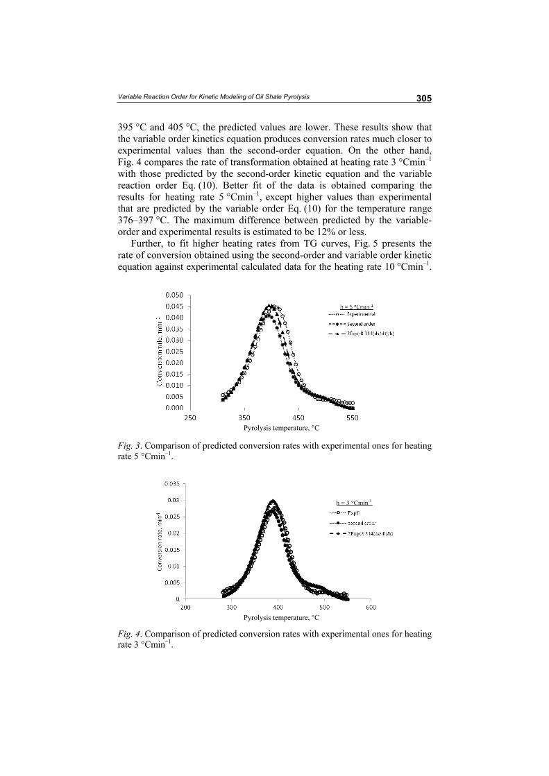
Figure 3 shows conversion rate predicted basing on the second-order equation and variable order calculated by Eq. (12) using experimental data obtained at heating rate 5 °Cmin–1. It is clear from the figure that employing a variable reaction order for the conversion function results in a better fit to experimental data than the second order for f(x). Exponent of the second-order and variable order kinetic equations predict higher conversion rate values up to pyrolysis temperature 390 °C, while at higher temperatures, i.e.
Variable Reaction Order for Kinetic Modeling of Oil Shale Pyrolysis
305
395 °C and 405 °C, the predicted values are lower. These results show that the variable order kinetics equation produces conversion rates much closer to experimental values than the second-order equation. On the other hand, Fig. 4 compares the rate of transformation obtained at heating rate 3 °Cmin–1 with those predicted by the second-order kinetic equation and the variable reaction order Eq. (10). Better fit of the data is obtained comparing the results for heating rate 5 °Cmin–1, except higher values than experimental that are predicted by the variable order Eq. (10) for the temperature range 376–397 °C. The maximum difference between predicted by the variable-order and experimental results is estimated to be 12% or less.
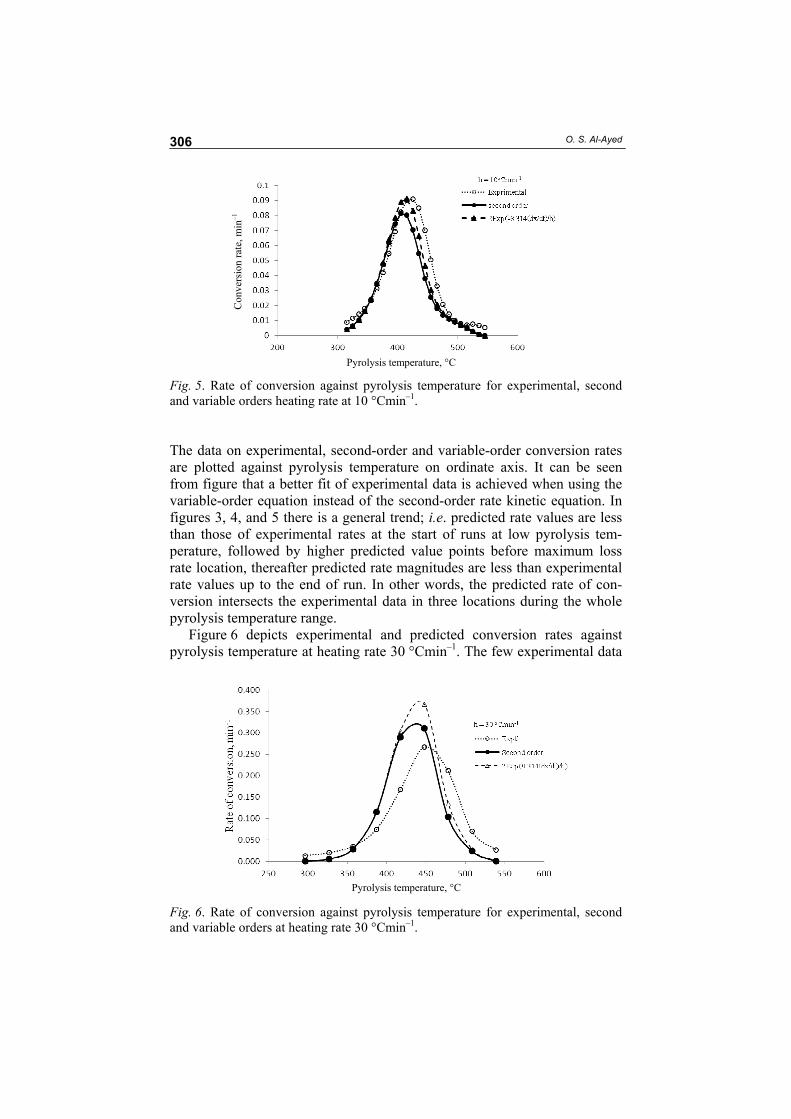
Further, to fit higher heating rates from TG curves, Fig. 5 presents the rate of conversion obtained using the second-order and variable order kinetic equation against experimental calculated data for the heating rate 10 °Cmin–1.
Fig. 3. Comparison of predicted conversion rates with experimental ones for heating rate 5 °Cmin–1.
Fig. 4. Comparison of predicted conversion rates with experimental ones for heating rate 3 °Cmin–1.
Pyrolysis temperature, °C
Pyrolysis temperature, °C
h = 3 °Cmin-1
O. S. Al-Ayed
306
Fig. 5. Rate of conversion against pyrolysis temperature for experimental, second and variable orders heating rate at 10 °Cmin–1. The data on experimental, second-order and variable-order conversion rates are plotted against pyrolysis temperature on ordinate axis. It can be seen from figure that a better fit of experimental data is achieved when using the variable-order equation instead of the second-order rate kinetic equation. In figures 3, 4, and 5 there is a general trend; i.e. predicted rate values are less than those of experimental rates at the start of runs at low pyrolysis tem-perature, followed by higher predicted value points before maximum loss rate location, thereafter predicted rate magnitudes are less than experimental rate values up to the end of run. In other words, the predicted rate of con-version intersects the experimental data in three locations during the whole pyrolysis temperature range.
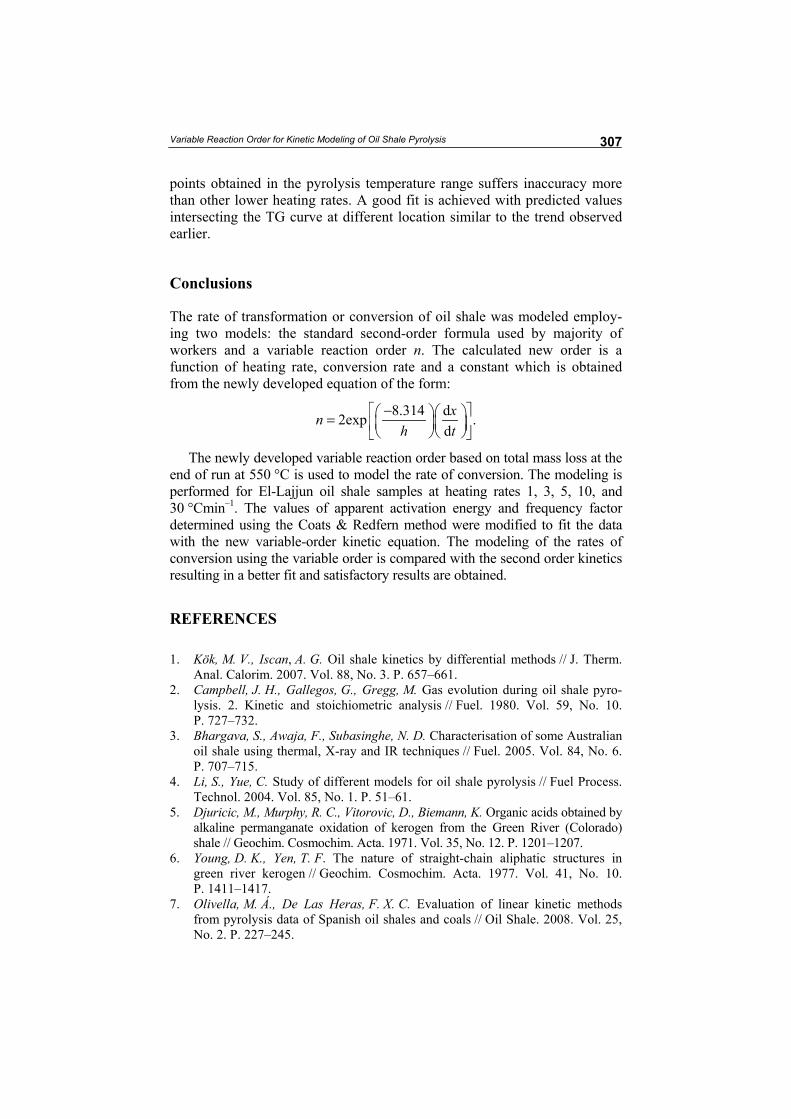
Figure 6 depicts experimental and predicted conversion rates against pyrolysis temperature at heating rate 30 °Cmin–1. The few experimental data
Fig. 6. Rate of conversion against pyrolysis temperature for experimental, second and variable orders at heating rate 30 °Cmin–1.
Pyrolysis temperature, °C
Pyrolysis temperature, °C
Con
vers
ion
rate
, min
–1
Variable Reaction Order for Kinetic Modeling of Oil Shale Pyrolysis
307
points obtained in the pyrolysis temperature range suffers inaccuracy more than other lower heating rates. A good fit is achieved with predicted values intersecting the TG curve at different location similar to the trend observed earlier.
Conclusions
The rate of transformation or conversion of oil shale was modeled employ-ing two models: the standard second-order formula used by majority of workers and a variable reaction order n. The calculated new order is a function of heating rate, conversion rate and a constant which is obtained from the newly developed equation of the form:
8.314 d2exp .dxn
h t− =
The newly developed variable reaction order based on total mass loss at the end of run at 550 °C is used to model the rate of conversion. The modeling is performed for El-Lajjun oil shale samples at heating rates 1, 3, 5, 10, and 30 °Cmin–1. The values of apparent activation energy and frequency factor determined using the Coats & Redfern method were modified to fit the data with the new variable-order kinetic equation. The modeling of the rates of conversion using the variable order is compared with the second order kinetics resulting in a better fit and satisfactory results are obtained.
REFERENCES
1. Kök, M. V., Iscan, A. G. Oil shale kinetics by differential methods // J. Therm. Anal. Calorim. 2007. Vol. 88, No. 3. P. 657–661.
2. Campbell, J. H., Gallegos, G., Gregg, M. Gas evolution during oil shale pyro-lysis. 2. Kinetic and stoichiometric analysis // Fuel. 1980. Vol. 59, No. 10. P. 727–732.
3. Bhargava, S., Awaja, F., Subasinghe, N. D. Characterisation of some Australian oil shale using thermal, X-ray and IR techniques // Fuel. 2005. Vol. 84, No. 6. P. 707–715.
4. Li, S., Yue, C. Study of different models for oil shale pyrolysis // Fuel Process. Technol. 2004. Vol. 85, No. 1. P. 51–61.
5. Djuricic, M., Murphy, R. C., Vitorovic, D., Biemann, K. Organic acids obtained by alkaline permanganate oxidation of kerogen from the Green River (Colorado) shale // Geochim. Cosmochim. Acta. 1971. Vol. 35, No. 12. P. 1201–1207.
6. Young, D. K., Yen, T. F. The nature of straight-chain aliphatic structures in green river kerogen // Geochim. Cosmochim. Acta. 1977. Vol. 41, No. 10. P. 1411–1417.
7. Olivella, M. Á., De Las Heras, F. X. C. Evaluation of linear kinetic methods from pyrolysis data of Spanish oil shales and coals // Oil Shale. 2008. Vol. 25, No. 2. P. 227–245.

O. S. Al-Ayed
308
8. Thakur, D. S., Nuttall Jr., H. E. Kinetics of pyrolysis of Moroccan oil shale by thermogravimetry // Ind. Eng. Chem. Res. 1987. Vol. 26, No. 7. P. 1351–1356.
9. Karabakan, A., Yürüm, Y. Effect of the mineral matrix in the reactions of shales. Part 2. Oxidation reactions of Turkish Göynük and US Western Reference oil shales // Fuel. 2000. Vol. 79, No. 7. P. 785–792.
10. Yagmur, S., Durusoy, T. Kinetics of the pyrolysis and combustion of göynük oil shale // J. Therm. Anal. Calorim. 2006. Vol. 86, No. 2. P. 479–482.
11. Sütcü, H., Pişkin, S. Pyrolysis kinetics of oil shale from Ulukisla, Turkey // Oil Shale. 2009. Vol. 26, No. 4. P. 491–499.
12. Qing, W., Sun, B., Hu, A., Bai, J., Li, S. Pyrolysis characteristics of Huadian oil shales // Oil Shale. 2007. Vol. 24, No. 2. P. 147–157.
13. Jaber, J. O., Probert, S. D. Pyrolysis and gasification kinetics of Jordanian oil shales // Appl. Energ. 1999. Vol. 63, No. 4. P. 269–286.
14. Al-Ayed, O. S., Matouq, M., Anbar, Z., Khaleel, A. M., Abu-Nameh, E. Oil shale pyrolysis kinetics and variable activation energy principle // Appl. Energ. 2010. Vol. 87, No. 4. P. 1269–1272.
15. Al-Ayed, O. S., Suliman, M. R., Rahman, N. A. Kinetic modeling of liquid generation from oil shale in fixed bed retort // Appl. Energ. 2010. Vol. 87, No. 7. P. 2273–2277.
16. Qing, W., Hongpeng, L., Baizhong, S., Shaohua, L. Study on pyrolysis charac-teristics of Huadian oil shale with isoconversional method // Oil Shale. 2009. Vol. 26, No. 2. P. 148–162.
17. Vyazovkin, S., Wight, C. A. Model-free and model-fitting approaches to kinetic analysis of isothermal and nonisothermal data // Thermochim. Acta. 1999. Vol. 340–341. P. 53–68.
18. Torrente, M. C., Galan, M. A. Kinetics of the thermal decomposition of oil shale from Puertollano (Spain) // Fuel. 2001. Vol. 80, No. 3. P. 327–334.
19. Šestăk, J., Berggren, G. Study of the kinetics of the mechanism of solid-state reactions at increasing temperatures // Thermochim. Acta. 1971. Vol. 3, No. 1. P. 1–12.
20. Levenspiel, O. Chemical Reaction Engineering, 3rd ed. – New York: John Wiley & Sons, Inc., 1999.
21. Aboulkas, A., El Harfi, K. Study of the kinetics and mechanisms of thermal decomposition of Moroccan Tarfaya oil shale and its kerogen // Oil Shale. 2008. Vol. 25, No. 4. P. 426–443.
22. Skala, D., Kopsch, H., Sokić, M., Neumann, H.-J., Jovanović, J. Thermogravi-metrically and differential scanning calorimetrically derived kinetics of oil shale pyrolysis // Fuel. 1987. Vol. 66, No. 9. P. 1185–1191.
23. Johannes, I., Kruusement, K., Veski, R. Evaluation of oil potential and pyrolysis kinetics of renewable fuel and shale samples by Rock-Eval analyzer // J. Anal. Appl. Pyrol. 2007. Vol. 79, No. 1–2. P. 183–190.
24. Skala, D., Kopsch, H., Sokić, M., Neumann, H. J., Jovanović, J. A. Kinetics and modelling of oil shale pyrolysis // Fuel. 1990. Vol. 69, No. 4. P. 490–496.
25. Braun, R. L., Rothman, A. J. Oil-shale pyrolysis: Kinetics and mechanism of oil production // Fuel. 1975. Vol. 54, No. 2. P. 129–131.
26. Coats, A. W., Redfern, J. P. Kinetic parameter from thermogravimetric data // Nature. 1964. Vol. 201. P. 68–69.
Presented by I. Aarna Received October 11, 2010