![Time&variable gravity from GRACE: First resultsgeoid.colorado.edu/grace/docs/GRL-WahrSwenson2004.pdf2003 GRACE solution, and the static gravity field EGM96 [Lemoine et al., 1998] -](https://static.fdocuments.net/doc/165x107/6003cdbfe6f4526fff0dd2a1/timevariable-gravity-from-grace-first-2003-grace-solution-and-the-static.jpg)
VARIABLE GRAVITY RESEARCH FACILITY - NASA VARIABLE GRAVITY RESEARCH FACILITY University of North...
96
I VARIABLE GRAVITY RESEARCH FACILITY University of North Dakota Department of Space Studies De pa rtmen t of M echa n ica I Engineering Grand Forks, ND 58202 June 13,1988 (bASA-CB-lt47 14) VlElAELE G6LFIIY EESEABCH ~a9-193~4 IBCILI’LY Iliortt Iakota Uciv.) 5t FCSCL 1Ut3 Unclas G3/1U Olk39628 https://ntrs.nasa.gov/search.jsp?R=19890009953 2018-05-30T20:48:24+00:00Z
Transcript of VARIABLE GRAVITY RESEARCH FACILITY - NASA VARIABLE GRAVITY RESEARCH FACILITY University of North...

I
VARIABLE GRAVITY RESEARCH FACILITY
University of North Dakota
Department of Space Studies De pa rtme n t of M ec ha n ica I Engineering
Grand Forks, ND 58202
June 13,1988
(bASA-CB-lt47 14) V l E l A E L E G 6 L F I I Y EESEABCH ~ a 9 - 1 9 3 ~ 4 I B C I L I ’ L Y I l io r t t I a k o t a Uciv.) 5 t FCSCL 1Ut3
Unclas G3/1U Olk39628
https://ntrs.nasa.gov/search.jsp?R=19890009953 2018-05-30T20:48:24+00:00Z
I I
I I I
I I I I
VARIABLE GRAVITY RESEARCH FACILITY
University of North Dakota
Department of Space Studies Department of Mechanical Engineering
Grand Forks, ND 58202
June 13, 1988
Sean Allan Stan Ancheta Donna Beine Brian Cink Mark Eagon Brett Eckstein Dan Luhman
Daniel McCowan James Nations Todd Nordtvedt Mark Olson Roger Priebe Arlen Richards Robert Schick Paula Sollom Andy Tan
H. Robert Wasiuta
1 I I
I I I I I
I I I I
VARIABLE GRAVITY RESEARCH FACILITY
Chapter 1 THE SPIN AND DESPIN REQUIREMENTS
Chapter 2 ASSEMBLY OF A VARIABLE GRAVITY RESEARCH FACILITY
Chapter 3 POWER SYSTEMS TECHNOLOGY
Chapter 4 THERMAL CONTROL SYSTEM
Chapter 5 VGRF LIFE SUPPORT LOGISTICS
Chapter 6 SOLUTIONS TO POSSIBLE EMERGENCIES ABOARD THE VGRF
Chapter 7 ANTENNAE SOURCES AND COMMUNICATIONS
Chapter 8 USE OF RESIDUAL FUEL FROM EXTERNAL TANK
Chapter 9 TETHER LENGTHS AND ROTATION SPEEDS
Chapter 10 THE SUITABILITY OF THE SPACE STATION MODULES FOR THE VARIABLE GRAVITY RESEARCH FACILITY
Chapter 11 VARIABLE GRAVITY RESEARCH FACILITY MISSION ACTIVITIES
Chapter 12 CREW COMPARTMENT RECONFIGURATION
Chapter 13 COMPUTER MODELING AND SIMULATION OF TETHER VI BRAT1 ONS
Chapter 14 COST ESTIMATE
Chapter 15 TEST EQUIPMENT AND MODEL OF VGRF TO STUDY STABILITY OF TETHERS
1 I
~
I I 1 I I I I I I I I I 1 I I I I
ECLSS
CERV
ELV
ET
EVA
GEO
HM
LEO
MMU
OMS
RCS
RMS
RTG
ss VGRF
ABBREVIATIONS
Ecological Closed Life Support System
Crew Emergency Return Vehicle
Expendable Launch Vehicle
External Tank (for the Shuttle)
Extra Vehicle Activity
Geostationary Orbit
Habitation Module
Lower Earth Orbit
Manned Maneuvering Unit
Orbital Maneuvering System
Reaction Control System
Remote Manipulator System
Radioisotopic Thermoelectric Generator
International Space Station
Variable Gravity Research Facility
.i - . .. . ~
.. .. . .- -. . . .- -. .
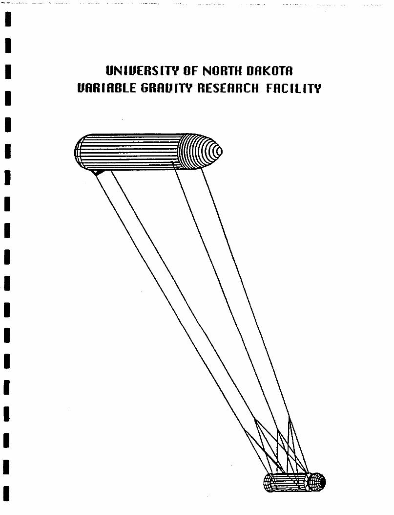
UNIUERSITY OF NORTH DRKOTfl UARIABLE GRflUlTY RESEflRCH FflCILITY
I I
I I I I I I I I I I I I I I I I I I I
Chapter 1
THE SPIN AND DESPIN REQUIREMENTS
1.1 Definition of Topic
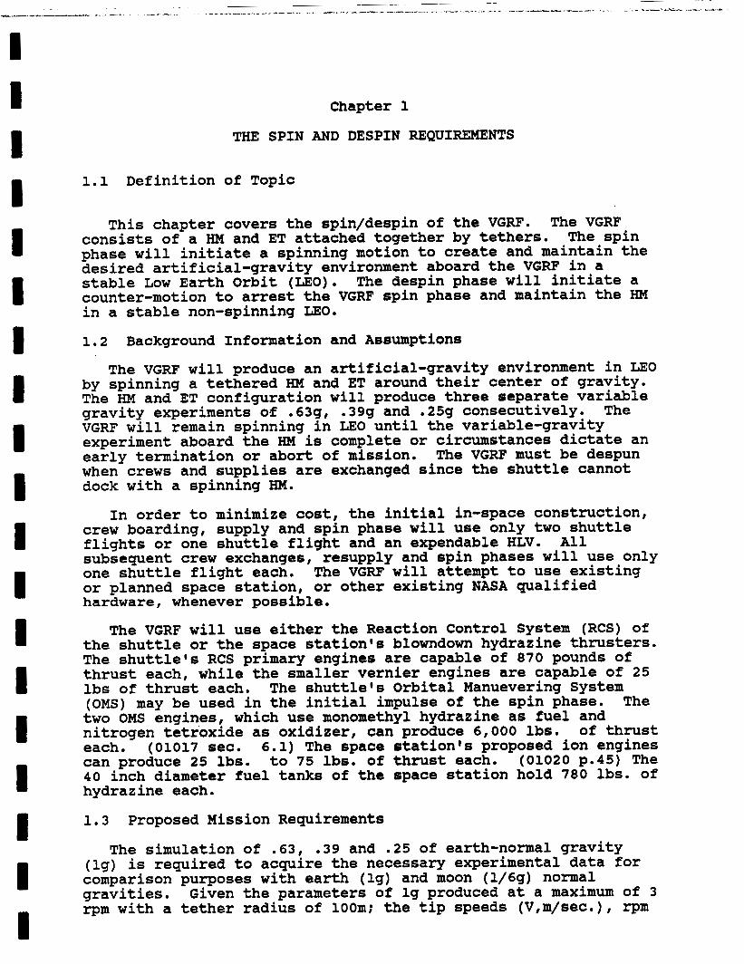
This chapter covers the spin/despin of the VGRF. consists of a HM and ET attached together by tethers. phase will initiate a spinning motion to create and maintain the desired artificial-gravity environment aboard the VGRF in a stable Low Earth Orbit (LEO). counter-motion to arrest the VGRF spin phase and maintain the HM in a stable non-spinning LEO.
The VGRF The spin
The despin phase will initiate a
1.2 Background Information and Assumptions
The VGRF will produce an artificial-gravity environment in LEO by spinning a tethered HM and ET around their center of gravity. The HM and ET configuration will produce three separate variable gravity experiments of .63g, .39g and .25g consecutively. The VGRF will remain spinning in LEO until the variable-gravity experiment aboard the HM is complete or circumstances dictate an early termination or abort of mission. when crews and supplies are exchanged since the shuttle cannot dock with a spinning HM.
The VGRF must be despun
In order to minimize cost, the initial in-space construction, crew boarding, supply and spin phase will use only two shuttle flights or one shuttle flight and an expendable HLV. subsequent crew exchanges, resupply and spin phases will use only one shuttle flight each. The VGRF will attempt to use existing or planned space station, or other existing NASA qualified hardware, whenever possible.
The VGRF will use either the Reaction Control System (RCS) of the shuttle or the space station's blowndown hydrazine thrusters. The shuttle's RCS primary engines are capable of 870 pounds of thrust each, while the smaller vernier engines are capable of 25 lbs of thrust each. (OMS) may be used in the initial impulse of the spin phase. The two OMS engines, which use monomethyl hydrazine as fuel and nitrogen tetroxide as oxidizer, can produce 6,000 lbs. of thrust each. (01017 sec. 6.1) The space station's proposed ion engines can produce 25 lbs. to 75 lbs. of thrust each. (01020 p.45) The 40 inch diameter fuel tanks of the space station hold 780 lbs. of hydrazine each.
All
The shuttle's Orbital Manuevering System
1.3 Proposed Mission Requirements
The simulation of .63, .39 and .25 of earth-normal gravity (lg) is required to acquire the necessary experimental data for comparison purposes with earth (lg) and moon (1/6g) normal gravities. rpm with a tether radius of 100m; the tip speeds (V,m/sec.), rpm
Given the parameters of lg produced at a maximum of 3
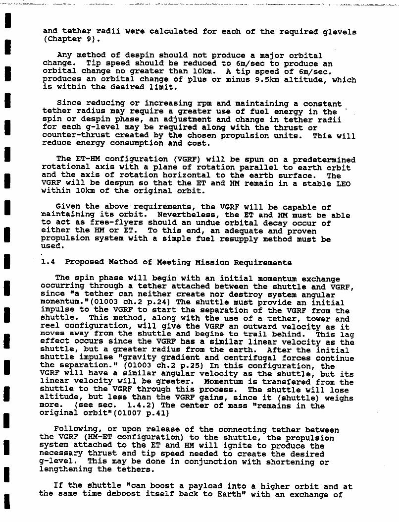
and tether radii were calculated for each of the required glevels (Chapter 9) .
Any method of despin should not produce a major orbital change. orbital change no greater than 1Okm. produces an orbital change of plus or minus 9.5km altitude, which is within the desired limit.
Tip speed should be reduced to 6m/sec to produce an A tip speed of 6m/sec.
Since reducing or increasing rpm and maintaining a constant tether radius may require a greater use of fuel energy in the spin or despin phase, an adjustment and change in tether radii for each g-level may be required along with the thrust or counter-thrust created by the chosen propulsion units. reduce energy consumption and cost.
'
This will
The ET-HM configuration (VGRF) will be spun on a predetermined rotational axis with a plane of rotation parallel to earth orbit and the axis of rotation horizontal to the earth surface. The VGRF will be despun so that the ET and HM remain in a stable LEO within lOkm of the original orbit.
Given the above.requirements, the VGRF will be capable of maintaining its orbit. to act as free-flyers should an undue orbital decay occur of either the HM or ET. To this end, an adequate and proven propulsion system with a simple fuel resupply method must be used . 1.4
The spin phase will begin with an initial momentum exchange occurring through a tether attached between the shuttle and VGRF, since @@a tether can neither create nor destroy system angular momentum.~~(01003 ch.2 p.24) The shuttle must provide an initial impulse to the VGRF to start the separation of the VGRF from the shuttle. This method, along with the use of a tether, tower and reel configuration, will give the VGRF an outward velocity as it moves away from the shuttle and begins to trail behind. This lag effect occurs since the VGRF has a similar linear velocity as the shuttle, but a greater radius from the earth. After the initial shuttle impulse "gravity gradient and centrifugal forces continue the separation.v1 (01003 ch.2 p.25) In this configuration, the VGRF will have a similar angular velocity as the shuttle, but its linear velocity will be greater. Momentum is transfered from the shuttle to the VGRF through this process. altitude, but less than the VGRF gains, since it (shuttle) weighs more. (see sec. 1.4.2) The center of mass "remains in the original orbit" (01007 p. 41)
Nevertheless, the ET and HM must be able
Proposed Method of Meeting Mission Requirements
The shuttle will lose
Following, or upon release of the connecting tether between the VGRF (HM-ET configuration) to the shuttle, the propulsion system attached to the ET and HM will ignite to produce the necessary thrust and tip speed needed to create the desired g-level. lengthening the tethers.
This may be done in conjunction with shortening or
If the shuttle "can boost a payload into a higher orbit and at the same time deboost itself back to Earth" with an exchange of
I I ~I I I I I 1 I I 1 I 1 I I I I I I
momentum as suggested for the spin phase, then a similar approaph can be used in the separation of the ET and HM within controlled limits. and separating the HM from the ET at a predetermined position upon the rotational axis, the HM will be boosted 9.5km while the ET will be lowered 9.5h in LEO.(figure 1.6) This may be done in conjunction with shortening or lenghthening the tethers and use of the propulsion system to reduce tip speed and save on fuel.
(01003 ch.2 p.27) By reducing the tip speed to 6m/sec.
Upon return of the shuttle for crew exchange and resupply, a new ET will be attached to the HM and the spin phase of the VGRF re-initiated for the next set of experiments at another g-level.
1.4.1 Discussion of Proposed Method
The proposed method of producing spin in order to create an artificial gravity environment aboard the VGRF has the following benefits: 1) it will use existing or proposed NASA qualified hardware: 2) it will require only a minimal amount of shuttle missions: 3) it will create the desired gravity levels of .63g, .39g and .25g.
The use of hydrazine resistojets have proven to be most reliable aboard the shuttle and similarly, @@[aJpplications analyses continue to show important economic benefits from the use of ion propulsion in satellite station keeping and orbit-raising.@I (01001) A multi-configuration of engines could produce the necessary thrust and altitude control. easily be refueled by use of their 40 inch diameter storage tanks .
They can
The benefits of the proposed method of despinning the VGRF are: 1) it is a simple separation procedure: 2) both the HM and ET will be completely recoverable in orbit (if desired for the ET); 3) 3 ET'S will be placed in orbit over the duration of the project and can be used for other purposes.
The HM will be re-used for each VGRF g-level stage and later used for the space station. If desired or required, the ET could be expended in a controlled de-orbit, where it would harmlessly be destroyed upon re-entry.
1.4.2 Weight Estimate of Proposed Method
The proposed mission requirements for weight must be within NASA specified launch restrictions. The combined weight of the ET and HM must be considerably less than the total shuttle weight in order for the momentum transfer techniques to be successful.
24,072kg more than the combined weight of the VGRF at 50,928kg: based upon a HM of 15,528kg (empty) (01020 p.456) and an ET of 35,400kg (empty). (01017, 7.28)
The shuttle weight of 75,000kg (empty) (01017, 7.2) is
The total propulsion system weight based upon an adapted LM system of 1,258kg (01020 p.456) for the HM and ET is 2,516kg. The weight of one 40 inch diameter fuel tank is 355kg. fuel tanks, 6 each for the HM and ET, based upon the space
Assuming 12
I I I 1 I I I I I I I 1 I I I I I I !
station requirement of 6 for the LM, the total weight for fuel tanks is 4,260kg.
12,605kg of fuel remains .in the ET from the original 718,500kg upon reaching orbit. This assumes a 5% left over. This fuel may be used for propulsion and is added to the total shuttle-VGRF weight on-orbit.
The required length and weight of the tethers have not been determined to date and depend on the exact location of the VGRF power system. Therefore the total estimated weight to date is 6,77 6kg.
1.5 Alternative Methods of Meeting Mission Requirements
Three other alternative methods were considered. They were: (1) the use of the shuttle RMS to initiate spin, (2) the use of a straight spin and despin, and (3) the use of a spin-up scheme proposed by UND student Jerry Petersburg. (used with permission)
1.5.1 First Alternative
By using the shuttle’s RMS it was thought that a spin could be initiated by attaching the RMS to the center of gravity between the HM and ET. This method was dismissed because it would require the shuttle to get dangerously close to a large spinning structure.
1.5.2 Second Alternative
The use of the HM and ET propulsion units for the spin phase and the despin phase was considered. This method was dismissed because of the additional fuel required by it when compared to that required by the prefered alternative.
1.5.3 Third Alternative
University of North Dakota student, Jerry Petersburg, has proposed to use counter weights attached to tethers located at the center of gravity, intersecting the HM and ET, to produce a counter-spin in the VGRF. This method was dismissed as it would require extensive testing.
1.6 Discussion of Unresolved Issues and Means of Resolving Them
This may be achieved through the use of attachment The synchronized separation of tethers for despin must be
resolved. point units which are released by explosive bolts.
Calculations for exact fuel requirements, tether lengths and spin/despin times must be made.
1.7 Summary
The VGRF will produce the required g-levels, within the required parameters, so that the effects of variable gravity may be studied. The proposed method, which will use existing NASA qualified hardware, will further reduce cost by saving fuel through a momentum transfer technique for both the spin and

I. - ---._
I 1 I I I I I I I I I I I I I I I I I
despin phases. By placing 3 ET'S in orbit over the life of the programme, an initial step towards meeting the National Commission On Space's recommendation for using ET'S in orbit will be made. The VGRF will most likely meet the President's challenge to place a space station in orbit by 1994.
1 . 8 References
01001
01002
01003
01004
01005
01006
01007
01008
01009
01010
01011
01012
01013
01014
Aerospace highlights. 1986. Electric propulsion. Aerospace America. Dec.
Torques on the three dimensional motion of a rotating space station. 12p. Washington D.C.: Amer. Inst. of Aeronautics and Astronautics.
Baracat, W.A. and C.L. Butner. 1986. Tethers in space handbook. Washington D.C.: NASA.
Baracat, W.A. 1986. Applications of tethers in space. NASA conf. pub. 2422 Workshop procedings 2 Oct. 15-17, 1985. Washington D . C . : NASA. Baudy, W.A. 1972. Simulation of a flexible spinning vehicle. 104p. Washington D.C.: NASA.
Beer, F.P. and E.R. Johnston, Jr. 1976. Mechanics for engineers dynamics. 3rd ed., Mcgraw-Hill.
Bekey, I. and P.A. Penzo. 1986. Tether propulsion. Aerospace Amer. July: 40-43
Berman, H. et a1.1972. Stability and cmg wobble damping of flexible, spinning space stations. 15p. Washington D.C.: Amer. Inst. of Aeronautics and Astronautics.
Carroll, J.A. 1985. Guidebook for analysis of tether applications. Martin Marietta Corp.
Childs, D.W. and T.L. Hardison. 1974. A movable-mass attitude stabilization system for cable-connected artificial-g space stations. Jour. of Spacecraft and Rockets. 11 (3); 165-173
Cron, A.C. 1985. Applications of tethers in space, vol. 2. 319p. Washington D.C. : NASA.
Curtis, H.S. 1971. On the use of control movement gyros for wobble damping of an artificial gravity skylab. 8p. Washington D.C.: Amer. Inst . of Aeronautics and Astronautics.
Grey, J. 1987. Space station careens past all obstacles. Aerospace America. Sept; 24-28
Hammersmith, J.L. (study manager). 1970. Artificial gravity experiment
I I I I I I I I I I I I I I I I I I I
Chapter 2
ASSEMBLY OF A VARIABLE GRAVITY RESEARCH FACILITY
2.1 Definition of Topic
This chapter discusses the sequence of activities required to assemble the VGRF. Trade-offs between several different approaches are examined.
2.2 Background Information
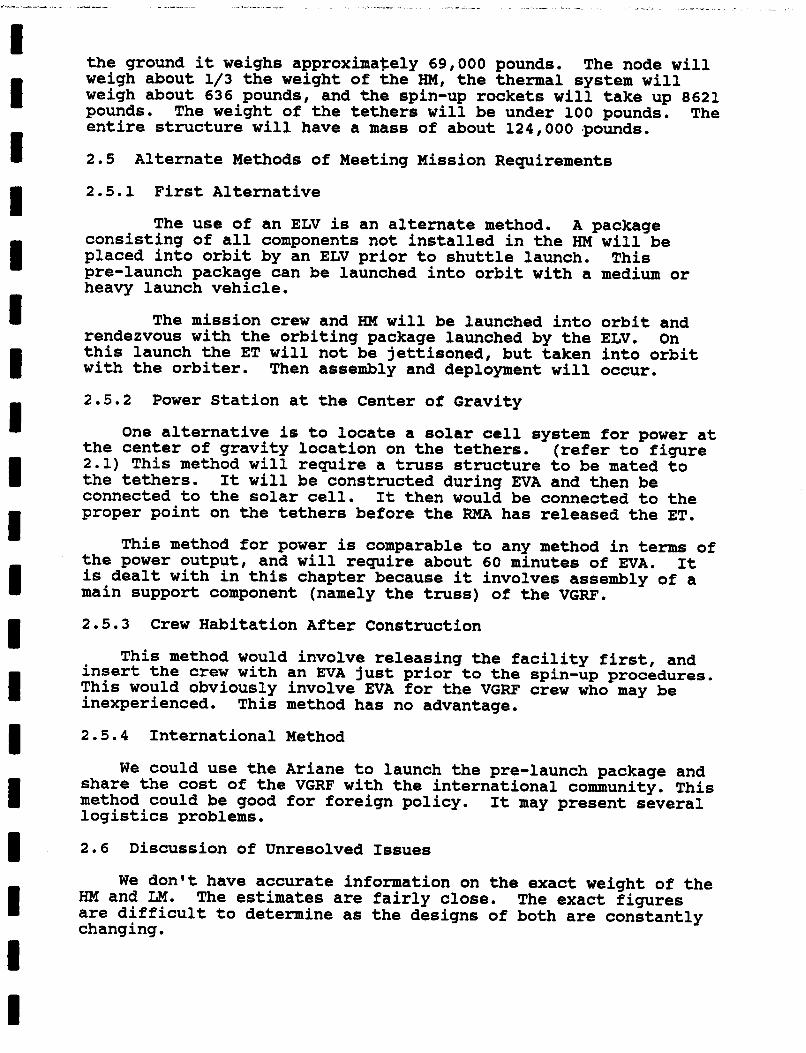
The basic assumption is that the facility will be lifted into orbit by the space shuttle. Additional access to orbit could come from an expendable launch vehicle (ELV) . The VGRF will be a simple facility consisting of two separate structures, connected by four "kevlarll tethers, that rotate about the center of gravity of the entire facility. structures will be a habitation module (HM) with a crew emergency return vehicle (CERV) and a resource node attached to either end: this hardware is all from the Space Station. The HM is 38.7 feet long, while the node will be approximately 15 feet long. Both modules are about 14 feet in diameter. Specific information on the CERV is not available. external fuel tank (ET) brought up to orbit by the shuttle. It is 153.8 feet long and 27.6 feet in diameter.
We will assume a maximum space shuttle cargo capacity of 34,000 pounds, and 34,000 pounds as the weight of the HM alone. This will make a single shuttle launch unfeasible.
2.3 Proposed Mission Requirements
(refer to figure 2.1) One of the
The other structure will be an
The entire structure, including crew, tethers, life support, experiments, food, and vital equipment, will be carried on the fewest shuttle launches possible. The entire assembly process must use current technology or technology that has been developed f o r the Interntional Space Station. minimal EVA. tethers and remote ET and cargo bay releases.
Assembly will require This will necessitate the use of quick connect
Since the three missions proposed for the facility study gravity levels from -225 g to .64 g, equipment stressed for 1 g will be acceptable for the VGRF.
This facility must be assembled in such a way as to facilitate minimal effort when reconstructing the space station. No welding, permanent attachments or permanent changes to the HM o r node may be made.
2.4 Proposed Method of Meeting Mission Requirements
This method would use two shuttle launches as the sole means of launching the VGRF.
I I I I I I I I I I I I I I I I I I 1
Flight One
This will be a VGRF dedicated flight. The only payload will be the fully-equipped HM. connected to the HM on the ground. and left in LEO. flight.
The spin-up/RCS rockets will be
The ET is not needed for the VGRF on this The package is then launched
Flight Two
This flight will carry the'three person mission crew and remaining hardware (node, CERV, and tethers) into orbit. Upon reaching orbit the ET will remain attached to orbiter, the shuttle will rendezvous with the HM and assembly is initiated.
Once rendezvous is accomplished, the CERV is manned and The node is then deployed to dock with the free-flying HM.
attached. attachment points and to the HM. Martin Marietta Corp.)
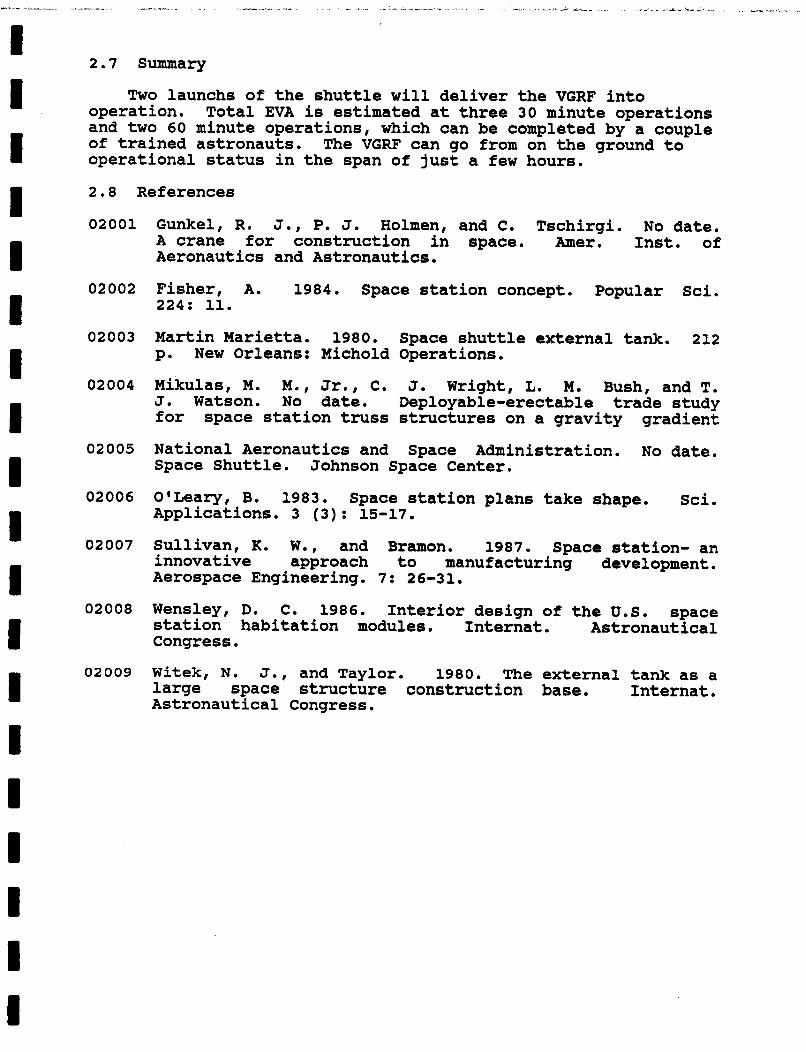
The tethers are attached to both the ET interface (refer to #1 in figure 2.2,
~n astronaut in a manned maneuvering unit (MMU) will take one tether at a time to the ET and install them with the attachments shown in figure 2.3 (Martin Marietta Corp.). Two tethers will be attached to the ET/Solid Rocket Booster interfaces with the adapters as shown. Two other tethers will be attached to the aft ET/Orbiter interfaces with the adapters as shown (also refer to #2 and #3, respectively, of figure 2.2). Each of these operations will require approximately 30 minutes of EVA.
Another astronaut tethered in the cargo bay will attach the other ends of the ET tether to the handling points on the HM. The process here will need to be worked out to insure that the tethers can not catch on any parts of the shuttle or VGRF. Another 60 minutes will be required to attach spin-up/maneuvering rockets to the ET. Once all connections have been made and the crew is on board, the VGRF (HM, CERV, and node) will be gently deployed from the cargo bay.
Then the crew is transfered to the VGRF.
The shuttle then executes a roll manuever to straighten the tethers and bring the ET around for separation.
2.4.1 Discussion of the Proposed Method
The crew remains in the relative safety of the orbiter or the HM for the entire process, leaving the only EVA left to trained astronauts. the pre-launched package due to unexpected problems with the ELV (ie: Skylab's problems), or lack of control of the ET during
HM-LM connection, when the ET is floating unsecured (this is not likely to be a problem as the shuttle is very capable of maneuvering in orbit) .
The possible limitations include: possible damage to
2.4.2 Weight Estimate of Proposed Method
The maximum space shuttle cargo weight at lift off is 34,000 pounds, the HM will weigh approximately 34,000. taking the ET to orbit doesn't reduce potential cargo weight.
For our purposes On
'I^ -_-
I I I I I 1 I I 1 ! I I I I I I I I I
the ground it weighs approxima$ely 69,000 pounds. weigh about 1/3 the weight of the HM, the thermal system will weigh about 636 pounds, and the spin-up rockets will take up 8621 pounds. The entire structure will have a mass of about 124,000 .pounds.
The node will
The weight of the tethers will be under 100 pounds.
2.5
2.5.1 First Alternative
Alternate Methods of Meeting Mission Requirements
The use of an ELV is an alternate method. A package consisting of all components not installed in the HM will be placed into orbit by an ELV prior to shuttle launch. pre-launch package can be launched into orbit with a medium or heavy launch vehicle.
This
The mission crew and HM will be launched into orbit and rendezvous with the orbiting package launched by the ELV. this launch the ET will not be jettisoned, but taken into orbit with the orbiter.
2.5.2
On
Then assembly and deployment will occur.
Power Station at the Center of Gravity
One alternative is to locate a solar cell system for power at the center of gravity location on the tethers. 2.1) This method will require a truss structure to be mated to the tethers. connected to the solar cell. It then would be connected to the proper point on the tethers before the RMA has released the ET.
the power output, and will require about 60 minutes of EVA. It is dealt with in this chapter because it involves assembly of a main support component (namely the truss) of the VGRF.
2.5.3 Crew Habitation After Construction
(refer to figure
It will be constructed during EVA and then be
This method for power is comparable to any method in terms of
This method would involve releasing the facility first, and insert the crew with an EVA just prior to the spin-up procedures. This would obviously involve EVA for the VGRF crew who may be inexperienced. This method has no advantage.
2.5.4 International Method
We could use the Ariane to launch the pre-launch package and
It may present several share the cost of the VGRF with the international community. This method could be good for foreign policy. logistics problems.
2.6 Discussion of Unresolved Issues
We don't have accurate information on the exact weight of the HM and LM. are difficult to determine as the designs of changing.
The estimates are fairly close. The exact figures both are constantly
I I I I I I I I I I I I I I I I D I 1
2.7 Summary
Two launchs of the shuttle will deliver the VGRF into operation. Total EVA is estimated at three 30 minute operations and two 60 minute operations, which can be completed by a couple of trained astronauts. operational status in the span of just a few hours.
The VGRF can go from on the ground to
2.8 References
02001 Gunkel, R. J., P. J. Holmen, and C. Tschirgi. No date. A crane for construction in space. Amer. Inst. of Aeronautics and Astronautics.
02002 Fisher, A. 1984. Space station concept. Popular Sci. 224: 11.
02003 Martin Marietta. 1980. Space shuttle external tank. 212 p. New Orleans: Michold Operations.
02004 Mikulas, M. M., Jr., C. J. Wright, L. M. Bush, and T. J. Watson. No date. Deployable-erectable trade study for space station truss structures on a gravity gradient
02005 National Aeronautics and Space Administration. No date. Space Shuttle. Johnson Space Center.
02006 O'Leary, B. 1983. Space station plans take shape. Sci. Applications. 3 (3) : 15-17.
02007 Sullivan, K. W., and Bramon. 1987. Space station- an innovative approach to manufacturing development. Aerospace Engineering. 7: 26-31.
02008 Wensley, D. C. 1986. Interior design of the U.S. space station habitation modules. Internat. Astronautical Congress .
02009 Witek, N. J., and Taylor. 1980. The external tank as a large space structure construction base. Internat . Astronautical Congress.
W
nc
LL
v) r
c W
w 0 U a G w c.
t;
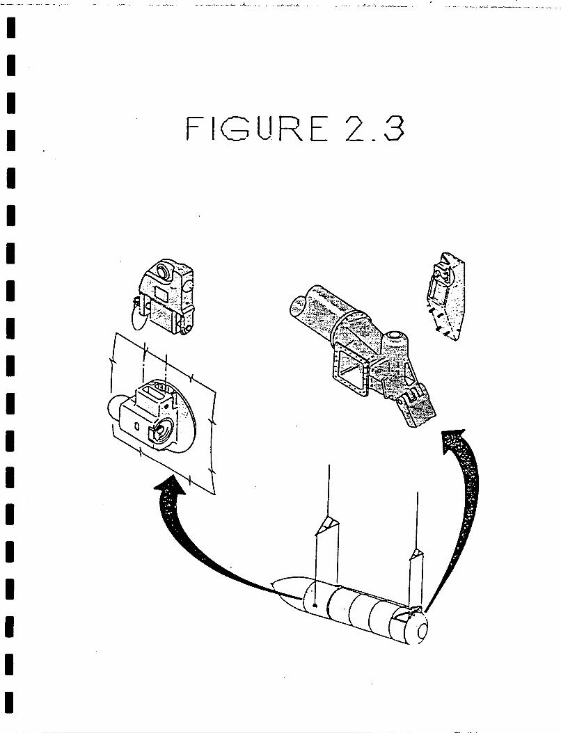
FIGURE 2-3
-... .
I I I I I I I I I I I I I I I I I I I
Chapter 3
. POWER SYSTEMS TECHNOLOGY
3.1 Definition of Topic
Power generation, energy storage, power management and distribution subsystems (PMAD) are elements necessary for extended habitation experiments in space. Thus, the type of power system selected and the energy requirements will play a major role in a mission such as the Variable Gravity Research Facility (VGRF). Of particular interest, are high efficiency, radiation tolerant, lightweight solar cells combined with high strength components and advanced techniques for blanket and array assembly.(3030) Recent developments in the technology of energy conversion are evaluated and discussed with specific regard for the type of power-conversion requirements. The technology best suited for a reliable and safe mission on the VGRF is the central focus of this research. Unlike previous missions, such as Skylab, today there is a desire for integrated systems capable of fulfilling a variety of mission requirements.(3002)
3.2 Background Information
Photovoltaic solar arrays have been the major source of electric power for satellites, other free-flying modules, and the the orbiting laboratory Skylab. necessary power for instmentation and equipment, solar arrays have also provided sufficient electricity for life support systems.
In addition to supplying the
Testing to date has shown that the solar arrays will perform well under space conditions; however, the limiting factor is the extended eclipse time resulting from the rotation of the VGRF. The VGRF will spend approximately one-third of its orbital time shaded by the earth and two-thirds of the remaining time shaded by its rotation (shaded time approximately 78% of total); thus, the amount of available collection time will be greatly reduced. Therefore, power requirements for the VGRF would have to be supplemented with a high efficiency energy storage system. (3022)
VGRF is the question of durability once the facility is rotating and gravity is present. been developed to provide reliable power in a 0 g environment. A question arises as to whether the placement of the arrays will be affected by the creation of near 1 g. The Solar Array Experiment Project of 1984 showed that a deployed solar array could perform well under high stress conditions and continue to produce 90 w/kg of power. (3022)
An additional concern in determining a power system for the
Traditional photovoltaic arrays have
In addition to maintaining life support system requirements, the VGRF could be used to test high energy systems for future projects such as the space station. requirements are minimal considering that Skylab managed to support a mission on less than 10 kWe (3010) (3021).
In general, the VGRF energy
I I I I I I I I I 1 I I I I I I 1 I I
3.3 Proposed Mission Requirements
The VGRF project being researched requires a power system capable of operating in a space environment with a maximum level of gravity at .64g. This facility will be in constant rotation and will therefore, require a power system capable of generating energy while constantly alternating between solar and eclipse periods. Of particular interest is a hybrid solar power system that utilizes photovoltaic collectors for operational control and nickel-hydrogen (NiHi) batteries or regenerative fuel cells for eclipse phase power. (3015) (3030)
The VGRF will be performing a series of experiments to test human adaptation levels to a various gravity environments. Power capacity requirement is minimal and approximately 30 kWe should be adequate. distribution and thermal control, 2 kWe for housekeeping and 14 kWe for other functions. This amount is considerably less than the 100 kWe suggested for the space station. Once the VGRF project has expired, the power system can then be transferred to supply part of the initial operating capacity (IOC) power requirements of the Space Station.
This translates into 14 kWe for basic power
3.4 Proposed Method of Meeting Mission Requirements
A 30kWe hybrid photovoltaic GaAs solar array power system combined with either a Ni-Hi regenerative fuel cell or Ni-Hi battery power generation subsystem will provide the necessary energy to fill the VGRF mission requirements. system must be equipped with a fully autonomous power management control system capable of constantly reacting to changes in the VGRF's rotation and placement toward the sun. that the PV array will be extended by a suitable tether system toward the center of rotation to take advantage of limiting stress factors on the extended array configuration. As tested on STS 41-D the extended STACBEAM arrangement of PV arrays could be used to retract and restow the arrays during periods of spin up/spin down of the VGRF. (3030) (3027)
3.4.1 Discussion of Proposed Method
In addition the
This will mean
The Photovoltaic power generation subsystem (PGS) solar array will consist of eight solar wings sized for full-power capability (30kWe) with one wing shut down. Each wing should have two identical blanket assemblies, each stowed in a container cover assembly. The two container cover assemblies are hinged to a mast structurally connected to the VGRF with eight STACBEAM solar array or some other form of tether assembly. This will allow the arrays the opportunity to pivot on command, thus tracking the sun so as to attract the maximum amount of solar energy. containers also articulate and the mast assembly extends to lift the solar array blanket to its deployment position. extended position, the blanket may also be retracted and restowed for wing maintenance, disposal or spin up/spin down periods. (3035) (3030)
The dual
From any
If the energy storage system (ESS) is a regenerative fuel cell(RFC) based on the space transportation system (STS), there should be 4 RFCs located in two groups of two and located just
I I I I I I I I I I u I I I U I I I
outboard of the habitation module ends. Each RFC consists of a fuel cell assembly, an electrolizer assembly, fluid management hardware reactant storage tanks and a thermal control interface. Although RFCs have a reserve reactant to handle contingency requirements, safe haven power is provided by fuel cells derived from a proven STS design using an advanced NASA designed individual pressurized vessel (IPV) for nickel hydrogen cells.(3027) Reactants are also preheated using fuel cell waste heat. (3016) (3019) (3035)
The power management and distribution (PMAD) subsystem configuration must be designed to accept solar array and RFC dc power and convert it into high-voltage AC power for distribution. Multiple interconnectable busses will maximize the utility of individual PV arrays and RFC sources. Thus, the nominal source voltage must also be changed from the previous 28 v system to a 100 - 110 volt system. This can be accomplished by switching between voltage regulators during eclipse periods and alternative units during sunlight. Thermal control of RFCs and local PMAD equipment can be provided by a twophase fluid loop coupled to a radiator. (3010) (3020) (3027) (3031)- (3035)
Available W cell types are silicon ( S i ) and gallium arsenide (GaAs). Although GaAs cells offer advantages (high efficiency, require less area, and reduce aerodynamic drag in L E O ) , their cost is considerably higher than that of fifty-micron Si cells. (3021) (3022) Using concentrators with GaAs cells reduces the required cell area, thereby moderating the cost difference. A range of Si cell thickness is available. deployed to date has been 7.9 cm by 7.9 cm. Cell thickness affects blanket mass and therefore the structural dynamics of the array which in turn affects the costs for manufacturing and handling a PV array. back verses continuous back contacts. IR transparent, the cell transparency offered by the gridded back contact would allow the cells to run cooler and thus operate more efficiently. Single junction GaAs concentrator cells have reached 22% efficiency at 100 suns at 80 C; multiple junction cascade cells should reach efficiency levels above 30% soon. (3021) (3022) (3035)
The largest cell array
Cell configuration options include gridded If the array substrate is
3.4.2 Weight Estimate of Proposed Method
The critical element of concern in selecting a power system for the VGRF is the power-to-weight generated ratio and subsequent efficiency ratings. To date NASA has tested three cell designs. A 2cm by 4cm by 1/50cm thick array with a 13% efficiency rating producing 13 watts of useful power. A 5.9cm by 5.9cm by 1/50cm thick array has also been rated as producing 13 watts of useful power. Lastly, a 2cm by 2cm by 1/200cm thick array with a 10.5% efficiency rating has also been evaluated. design a W solar array that produces the most power possible with the lightest available materials. close to 66 watts per kilogram of weight, but new high efficiency cells will likely raise this amount to about 75 watts. percent efficient cell, solar array blanket specific powers of 300 w/kg and 90 w/kg were achieved using either Kapton or a Kapton-graphite-aluminum honeycomb core graphite, respectively.
The goal is to
Current designs produce
For a 13
I I I 1 I 1 1 I 1 I I B I I I 1 1 I I
The approximate weight for a solar array system is llOOkg or 59 w/kg. The cells weigh 350kg, the cover glass and wire weigh 175kg, the hinges, inter-connects & adhesive weigh 200k9, the blanket box weighs lOOkg and the mast and canister 125kgs. The power system containing RFGs or NIHi batteries, electrical connections and distribution system including the autonomous power management system weighs approximately 5580kg or 4.5 w/kg for a 25kW space platform. will increase this figure by 500kg making the power system of the VGRF weigh approximately 6080kg. (3010) (3011) (3027)
The VGRF system requirements of 30kW
3.5 Alternative Methods of Meeting Mission Requirements
3.5.1 In a solar dynamic system, the sun's rays are focused by a parabolic mirror into a receiver that heats a working fluid to drive an engine or turbine. electricity. In the process of thermal energy storage, salt stored in a receiver is heated by the sun and frozen during eclipse stages. working fluid provides thermal storage. The mirrors are held in hexagonal graphite-epoxy frames and consist of curved triangular reflecting facets. The frames are 14 feet across and capable of fitting in the Orbiters payload bay. Nickel-hydrogen batteries are used to store energy necessary for the eclipse stages.
An alternator then generates
The action of giving up the heat of fusion to
(3009) (3013) (3018)
Solar dynamic technology is not well proven in space; however, a strong technology base has been built in terrestrial and aeronautical applications. It has lower acquistion costs and is far more attractive than existing photovoltaic solar arrays for high power applications. In addition, the power management and distribution subsystem is designed to be user friendly, adaptable to growth and capable of accommodating changes in load type and size. efficiency compared to 14% for silicon solar cells. Its thermal energy storage efficiency of over 90% compared to a straight battery system's 70-80% and a fuel cells 55% makes solar dynamic technology an obvious choice for future space station requirements, but its large area requirements and untested nature do not make it a viable alternative at this time for the VGRF. (3009) (3013) (3001) (3006) ((3032)
Solar dynamic technology offers a 20.30%
3.5.2 The power system for the VGRF project could be fitted with either a Rankine or Brayton model engine. The organic Rankine cycle operates with toulene as the working fluid with a turbine inlet temperature of 750 degrees F. Rankine cycle units ranging in size from a few kilowatts to several hundred kilowatts have been used on earth and have proven to be reliable. The Brayton cycle with a helium-xenon working fluid and a turbine inlet temperature of 1300 degrees F have been tested over an extended duration with aircraft gas turbines and aircraft environmental control system turbine expanders. tested a single Brayton unit in a complete flow loop system in a simulated space vacuum for over 38,000 hours without difficulty. Although a hybrid of photovoltaic and solar dynamic systems will be used on the space station project no definite decision on the system type has been made. candidate for a hybrid power system before a final space station system is selected. (3005) (3012) (3029) (3032)
A 1960's NASA project also
The VGRF is therefore a likely
I I 1 I 1 I I I I I I I I I I I I I I
3.5.2 Another alternative power source is a nuclear powered radioisotopic thermoelectric generator (RTG). Instead of batteries, fuel cells or solar power sources the RTG produces a constant and reliable amount of energy when long term energy is required. When a naturally radioactive isotope decays, it produces heat, which is used to create electricity. RTG's have been used in Apollo experiments, Viking landers, Pioneer 10 f 11 probes, Voyager 1 t 2, Galileo, and planetary expeditions. Since there are no moving parts, the RTG has a high degree of reliability and are capable of producing high amounts of power. The RTG's are also compact and relatively light weight. In the Apollo missions an RTG powered by 3.5 kg plutonium-238 heat source 42 cm long, 6 cm in diameter and 7kg in weight produced 74 watts of power years after the project had concluded. (3007) (3024)
3.5.3 An additional option is the Free Piston Stirling SP-100. Using a nuclear powered generator at this time of launch uncertainty and public concern for safety is however, an unlikely scenario. Although, an SP-100 has been designed for low specific mass of 8 kg/kW and has been tested in a 4500hr plus demonstration, it has yet to receive the attention and credibility it deserves. (3025) (3026) (3032). If long term survivability was an issue or peak/pulse power availability was the concern, then the SP-100 would be the obvious choice. In essence, the SP-100 provides a compact high power system for projects requiring 300-400 kWe, but for the low power requirements of the VGRF nuclear power is simply not feasible. (3002) (3003) (3004) (3014) (3023)
3.6 Discussion of Unresolved Issues
The optimal place to locate the PV solar arrays has not been completely determined at this time. Available project funds will determine the type of solar and fuel cell arrays and batteries to be selected. the future program and attempt to develop a power system that can later be transferred to a space station which will follow the VGRF project .
At this time, it is best to consider the needs of
3.7 Summary
In order to meet the mission requirements of the VGRF a power system consisting of ultra light weight photovoltaic solar arrays and NiHi fuel cells or batteries should be selected. Since NASA has already developed the existing technology and has plans to use such a system on the space station, this presents an obvious advantage. In addition to providing a necessary margin of safety, such a system provides performance reliability and substantial economic benefits. and a power conversion system with an autonomously managed power control system will ensure that the VGRF will operate with minimal complication. The VGRF is an excellent project for testing and evaluating the major components that will eventually be required for the operational phase of the space station.
The principal feature of any space project is the type of power system that is to be deployed. Thus, in selecting an optimal power system questions of stability, control, cost and
The matching of energy storage
I I i 1 I I I I I 1 I I I I 1 1 I I I
station mass must be considered in addition to issues of required need, safety and output. Such selections are not easily resolved, therefore every opportunity to test operational systems must be carefully planned to reduce the possibility of potential error . 3.8 References
03001
03002
03003
03004
03005
03006
03007
03008
03009
03010
03011
Archer, J.S, E.S. Diamant, R.F. Kemp, J . W . Lockwood. 1986. Solar optics simulation for a space station solar dynamic power system, pp. 1909-1914. Proc. of the 21st intersociety energy conversion conference. Soc. of automotive engineers, San Diego, Cal. 3 vols.
Barthelemy, R.R., L.D. Massie, W.U. Borger. 1986. Military space power systems technology for the 21st century. pp. 1401-1404. Proc. of 21st intersociety energy conversion conference. SOC. of automotive Engineers.
Bents, D.J. 1985. Tethered nuclear power for the space station. pp. 1.210 -1.227. Proceedings of the 20th intersociety energy conference. society of automotive engineers.
Bermand, D.G., & R.K. Shaltens. 1986. DoE/NASA - automotive stirling engine project overview. pp. 430-435. Proc. of the 21st. Intersociety energy conversion conference. SOC. of automotive engineers.
Buden, D. Some thoughts on the commercial use of rectors in space. 1986. p. 1980-1981. Proc. of the 21st Intersociety energy conversion conference. SOC. of automotive engineers.
Carlson, A.W., E. Gustafson, K.L. McLallin. 1986. Solar dynamic power system heat projection. Proc. of the 21 st intersociety energy conversion conference. SOC. of automotive engineers.
Chien, P. 1987. Nuclear power - how safe in space. pp. 11-13. Space World. September.
Decker, D.K. & J.F. Campbell. 1986. A space station power management system architecture. pp. 1915-1918. Proc. of the 21st intersociety energy conversion conference. SOC. of automotive engineers.
Gilje, R.L. 1986. System implications of solar dynamic power. p. 2139. Proc. of the 21st Iintersociety energy conversion conference. SOC. of automotive engineers.
Guidici, R.J. 1985. Space station power system issues. pp. 1.79-1.83. Proc. of the 20th intersociety energy conversion conference. SOC. of automotive engineers. Hanson, I . G . 1986. Description of a 20 kilohertz power distribution system. 1986. pp. 1693-1694. Proc. of the 21st intersociety energy conversion conference. SOC. of automotive engineers.

4 1 I I I I I I I I I I 1 1 I I I 1 I
03012
03013
03014
03015
03016
03017
03018
03019
03020
03021
03022
03023
Heindenreich, G., T. Bland, R. Niggermann. Receiver for solar dynamic organic rankine cycle (ORC) powered space station. 1985. pp. 1.228- 1.245. Proc. of the 20th Intersociety energy conversion conference. SOC. of automotive engineers.
Holt, D.J. 1986. NASA chooses hybrid power system for space station. pp. 28-32. Aerospace Engineering. vol. VI, june.
Josloff, A.T. & W.S. Chui. 1986. Operational aspects of
1938-1941. Proc. of the 21st intersociety energy conversion conference. SOC. of automotive engineers.
spacecraft using space reactor power systems. PP.
Kempke Jr., E.E. 1985. Development of the power system for the U.S. manned space station. pp. 1.139 - 1.144. Proc. of the 20th intersociety energy conversion conference. soc. of automotive engineers.
Kuicki, K.K., & T. Ozeki, Y. Yoshida, 1985. A fundamental study of the alkaline - matrix - type fuel cell system for space vehic1es.B pp. 365-369. Space Solar Power Review. vol. v. Klawn, J.L., R.J. Staiger. 1985. Design tradeoffs for a space station solar - brayton power system. Proc. of the 20th intersociety energy conversion conference. SOC. of automotive engineers.
Kohout, L. 1986. Advanced solar thermal technologies for the 21st Century. pp. 208602093. Proc. of the intersociety energy conversion conference. SOC. of automotive engineers.
Lerner, E. 1987. Making solar batteries cheaper. p. 12. Aerospace America. february.
Massie, L.D. 1986. Integrated technology advanced power systems. pp. 2081-2085. Proc of the 21 st intersociety energy conversion conference. soc. of automotive engineers.
Matsui, Y., K. Kamimura, K. Sakurai, S. Kaminishi, T. Matsutani, T. Hirano, A. Suzuki.1985. Ultra thin silicon solar cell assembly technology. pp. 371-384. Space Solar Power Review. vol V.
Patterson, R.E., H.C. Mesch. 1986. Development of flight ready fifty micron - thick silicon cell array module technology. pp. 1468-1471. Proc. of the 21st intersociety energy conversion conference. SOC. of automotive engineers.
Schnyer, A.D., J.A. Sholtis, R.L. Verga, R.L. Wiley. 1985. SP 100 program developments. .pp. 1.17-1.25. Proc. of the 20th intersociety energy conversion conference. SOC. of automotive engineers.
1 I 1 1 I I 1 I I I I I I I I I I I I
03024
03025
03026
03027
03028
03029
03030
03031
03032
03033
03034
03035
Silverman, S.W. 1985. A nuclear reactor electrical power system for a manned space station in low earth orbit. pp 1.74-1.78. Proc. of the 20th intersociety energy conversion conference. SOC. of automotive engineers.
Slaby, J.G. 1985. Overview of the 1985 NASA-Lewis research center SP 100 free piston stirling engine activities. pp. 3.180-3.184. Proc. of the 20th intersociety energy conversion conference. SOC. of automotive engineers.
Slaby, J.G. 1986. Overview of the 1986 free piston stirling SP 100 activities at NASA-Lewis research center. pp. 420-429 Proc. of the 21st intersociety energy conversion conference. SOC, of automotive engineers.
Smithrick J. 1985. Initial performance of advanced designs for IPV- nickel-hydrogen cells. pp. 1.151-1.157. Proc. of the 20th intersociety energy conversion conference. soc. of automotive engineers.
Thaller, L.H., M.A. Manzo, O.D. Gonzalez-Sanabria. 1985. Design principles for nickel-hydrogen cells and batteries. pp. 1.45-1.50. Proc. of the 20th intersociety energy conversion conference. SOC. of automotive engineers.
Thomas, R.L. 1986. Power is the keystone. pp. 36-40. Aerospace America. September.
VanLandingham, E.E. 1986. The NASA space power technology program. pp. 1405-1410. Proc. of the 21st intersociety energy conversion conference. SOC. of automotive engineers.
Weeks, D., R.T. Bechtel. 1985. Autonomously managed high intersociety energy conversion conference. SOC. of automotive engineers.
W i l e y , R . L . ? A.D. Schnyer, J.A. Shol i t i s , R . L . V e r g a , E.J. Wahlquist. 1986. Space reactor power 1986, a year of choices and transition. pp 1411-1415. Proc. of the 21st intersociety energy conversion conference. SOC. of automotive engineers.
Broadhorst , H. W. 1986. Space power - emerging opportunities. pp 335-342 Acta Astronautica, vol. 16, October 1987.
Cassidy, J.F., T.J. Fitzgerald, R.I. Gilje, J.D. Gordon. 1986. Space power development impact on technology requirements. pp 323-333. Acta Astronautica, vol. 16, October 1987.
Friefeld, F.M., G.J. Hallinan, T.H. Springer, 1985. Space station power system technology -issues and development approach. pp 7.31-7.42. Proc. for the 22nd space congress. Space and society progress and promise. Cocoa Beach, Florida, April 23-26, 1985.
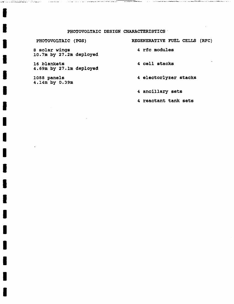
PHOTOVOLTAIC DESIGN CHARACTERISTICS
PHOTOVOLTAIC (PGS) REGENERATIVE FUEL CELLS (RFC)
8 solar wings 10.7m by 27.2m deployed
4 rfc modules
16 blankets 4.69m by 27.lm deployed
4 cell stacks
1088 panels 4.14m by 0.39m
4 electorlyzer stacks
4 ancillary sets
4 reactant tank sets
I I I I 1 I I I I I I 1 1 1 I I I 1 I
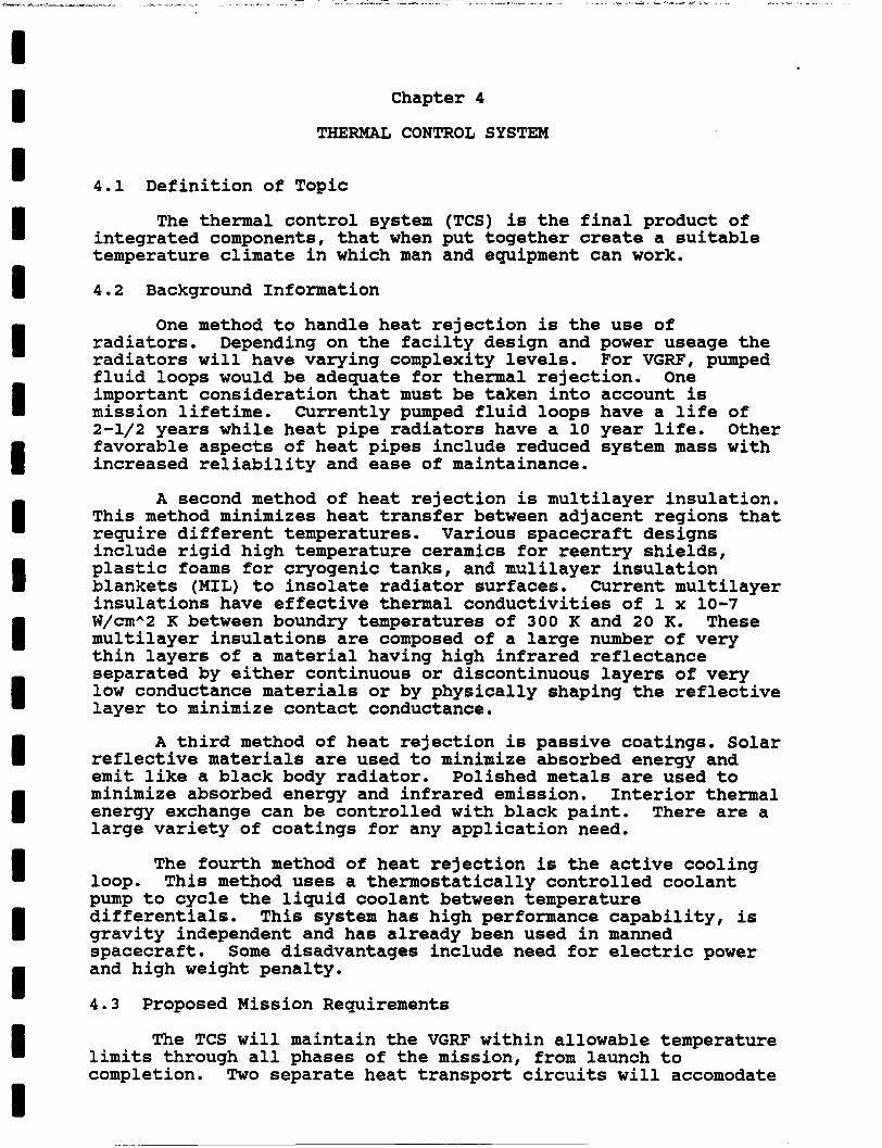
Chapter 4
THERMAL CONTROL SYSTEM
4.1 Definition of Topic
The thermal control system (TCS) is the final product of integrated components, that when put together create a suitable temperature climate in which man and equipment can work.
4.2 Background Information
radiators. Depending on the facilty design and power useage the radiators will have varying complexity levels. For VGRF, pumped fluid loops would be adequate for thermal rejection. important consideration that must be taken into account is mission lifetime. 2-1/2 years while heat pipe radiators have a 10 year life. Other favorable aspects of heat pipes include reduced system mass with increased reliability and ease of maintainance.
One method to handle heat rejection is the use of
One
Currently pumped fluid loops have a life of
A second method of heat rejection is multilayer insulation. This method minimizes heat transfer between adjacent regions that require different temperatures. Various spacecraft designs include rigid high temperature ceramics for reentry shields, plastic foams for cryogenic tanks, and mulilayer insulation blankets (MIL) to insolate radiator surfaces. Current multilayer insulations have effective thermal conductivities of 1 x 10⁻⁷ W/cmA2 K between boundry temperatures of 300 K and 20 K. These multilayer insulations are composed of a large number of very thin layers of a material having high infrared reflectance separated by either continuous or discontinuous layers of very low conductance materials or by physically shaping the reflective layer to minimize contact conductance.
A third method of heat rejection is passive coatings. Solar
Interior thermal
reflective materials are used to minimize absorbed energy and emit like a black body radiator. Polished metals are used to minimize absorbed energy and infrared emission. energy exchange can be controlled with black paint. large variety of coatings for any application need.
There are a
The fourth method of heat rejection is the active cooling loop. pump to cycle the liquid coolant between temperature differentials. This system has high performance capability, is gravity independent and has already been used in manned spacecraft. Some disadvantages include need for electric power and high weight penalty.
This method uses a thermostatically controlled coolant
4.3 Proposed Mission Requirements
The TCS will maintain the VGRF within allowable temperature limits through all phases of the mission, from launch to completion. Two separate heat transport circuits will accomodate
I I I I I I I I I I I I I I I I I I I
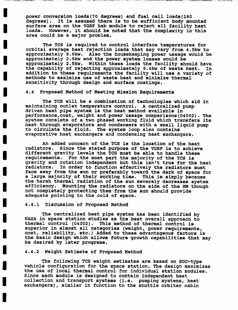
power conversion loads(70 degrees) and fuel cell loads(l60 degrees). It is assumed there is to be sufficient body mounted surface area on the VGRF hab module to reject all facility heat loads. However, it should be noted that the complexity in this area could be a major problem.
The TCS is required to control interface temperatures for orbital average heat rejection loads that may vary from 4.5- to approximately 9.9kw. Also the housekeeping power useage would be approximately 2.9- and the power system losses would be approximately 2.5kw. Within these loads the facility should have the capabilty of rejecting approximately 5.4- of waste heat. In addition to these requirements the facility will use a variety of methods to maximize use of waste heat and minimize thermal sensitivity through design and surface coatings.
4.4 Proposed Method of Meeting Mission Requirements
The TCS will be a combination of technologies which aid in maintaining outlet temperature control. driven heat pipe system is the best method available in performance,cost, weight and power useage comparisons(04002). The system consists of a two phased working fluid which transfers its heat through evaporators and condensers with a small liquid pump to circulate the fluid. evaporative heat exchangers and condensing heat exchangers.
A centralized pump
The system loop also contains
An added concern of the TCS is the location of the heat radiators. different gravity levels the TCS must be able to handle these requirements. gravity and rotation independent but this isn't true for the heat radiators. face away from the sun or preferably toward the dark of space for a large majority of their working time. the harsh thermal radiation of the sun severely decreases system efficiency. Mounting the radiators on the side of the IiM though not completely protecting them from the sun should provide adequate pointing to the cold of space.
4.4.1 Discussion of Proposed Method
Since the stated purpose of the VGRF is to achieve
For the most part the majority of the TCS is
In order to function effectively the radiators must
This is simply because
The centralized heat pipe system has been identified by NASA in space station studies as the best overall approach to thermal control (04002). This method of thermal control is superior in almost all categories (weight, power requirements, cost, reliability, etc.) Added to these advantageous factors is the basic design which allows future growth capabilities that may be desired by later programs.
4.4.2 Weight Estimate of Proposed Method
The following TCS weight estimates are based on SOC-type vehicle configuration for the space station. The design maximizes the use of local thermal control for individual station modules. Since each module is designed to contain independent heat collection and transport systems (i.e. pumping systems, heat exchangers), similar in function to the shuttle orbiter cabin
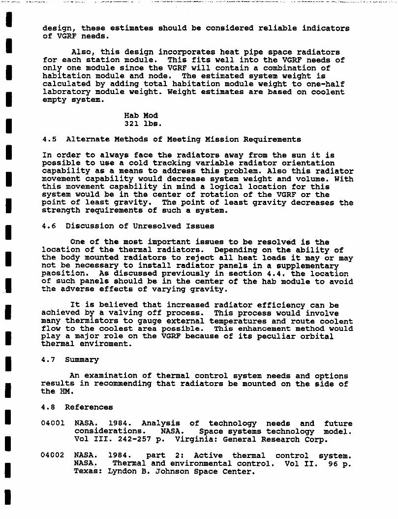
I I I I I I I I I I I I I I I I I I I
design, these estimates should be considered reliable indicators of VGRF needs.
Also, this design incorporates heat pipe space radiators for each station module. This fits well into the VGRF needs of only one module since the VGRF will contain a combination of habitation module and node. The estimated system weight is calculated by adding total habitation module weight to one-half laboratory module weight. Weight estimates are based on coolent empty system.
Hab Mod 321 lbs.
4.5 Alternate Methods of Meeting Mission Requirements
In order to always face the radiators away from the sun it is possible to use a cold tracking variable radiator orientation capability as a means to address this problem. Also this radiator movement capability would decrease system weight and volume. With this movement capability in mind a logical location for this system would be in the center of rotation of the VGRF or the point of least gravity. The point of least gravity decreases the strength requirements of such a system.
4.6 Discussion of Unresolved Issues
One of the most important issues to be resolved is the location of the thermal radiators. the body mounted radiators to reject all heat loads it may or may not be necessary to install radiator panels in a supplementary paosition. As discussed previously in section 4.4. the location of such panels should be in the center of the hab module to avoid the adverse effects of varying gravity.
achieved by a valving off process. many thermistors to gauge external temperatures and route coolent flow to the coolest area possible. This enhancement method would play a major role on the VGRF because of its peculiar orbital thermal enviroment.
Depending on the ability of
It is believed that increased radiator efficiency can be This process would involve
4.7 Summary
An examination of thermal control system needs and options results in recommending that radiators be mounted on the side of the HM.
4.8 References
04001 NASA. 1984. Analysis of technology needs and future considerations. NASA. Space systems technology model. Vol 111. 242-257 p. Virginia: General Research Cog.
04002 NASA. 1984. part 2: Active thermal control system. NASA. Thermal and environmental control. Vol 11. 96 p. Texas: Lyndon B. Johnson Space Center.
I I I I I I I I I I I I I I I I I I I
04003
04004
04005
04006
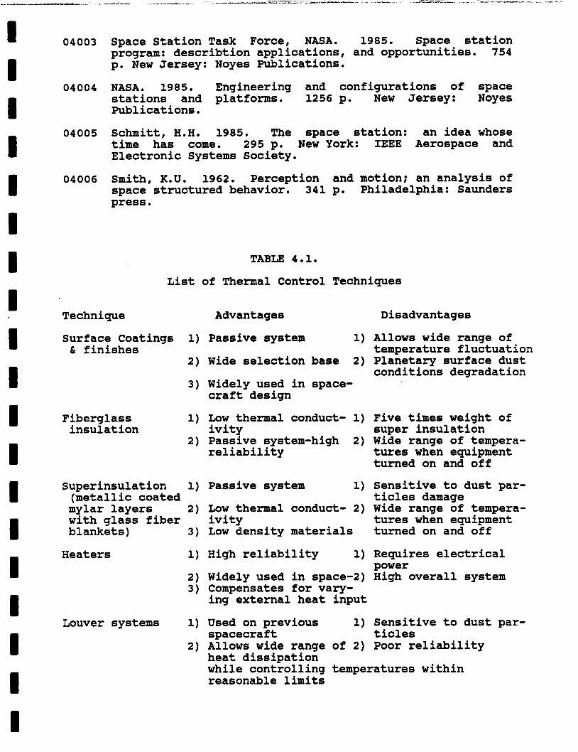
Space Station Task Force, NASA. 1985. Space station program: describtion applications, and opportunities. 754 p. New Jersey: Noyes Publications.
NASA. 1985. Engineering and configurations of space stations and platforms. 1256 p. New Jersey: Noyes Publications.
Schmitt, H.H. 1985. The space station: an idea whose time has come. 295 p. New York: IEEE Aerospace and Electronic Systems Society.
Smith, K.U. 1962. Perception and motion; an analysis of space structured behavior. 341 p. Philadelphia: Saunders press.
TABLE 4.1.
List of Thermal Control Techniques
Technique
Surface Coatings 1)
2) C finishes
3)
Fiberglass insulation
Superinsulation 1)
mylar layers 2)
blankets) 3)
(metallic coated
with glass fiber
Heaters 1)
Louver systems 1)
Advantages Disadvantages
Passive system 1) Allows wide range of temperature fluctuation
Wide selection base 2) Planetary surface dust conditions degradation
Widely used in space- craft design
Low thermal conduct- 1) Five times weight of ivity super insulation Passive system-high 2) Wide range of tempera- reliability tures when equipment
turned on and off
Passive system 1) Sensitive to dust par- ticles damage
Low thermal conduct- 2) Wide range of tempera- ivity tures when equipment Low density materials turned on and off
High reliability 1) Requires electrical power
Widely used in space-2) High overall system Compensates for vary- ing external heat input
Used on previous 1) Sensitive to dust par- spacecraft ticles Allows wide range of 2) Poor reliability heat dissipation while controlling temperatures within reasonable limits
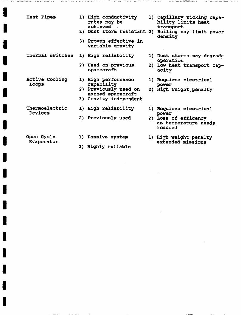
Heat Pipes 1) High conductivity 1) Capillary wicking capa-
2) Dust storm resistant 2) Boiling may limit power
3) Proven effective in variable gravity
rates may be achieved transport
bility limits heat
density
I I I I I I I
Thermal switches 1) High reliability 1) Dust storms may degrade
2) Used on previous 2) Low heat transport cap- operation
spacecraft acity
Loops capability power Active Cooling 1) High performance 1) Requires electrical
2) Previously used on 2) High weight-penalty manned spacecraft
3) Gravity independent
Thermoelectric 1) High reliability 1) Requires electrical Devices power
2) Previously used 2) Loss of efficency as temperature needs I reduced
Open Cycle Evaporator
1) Passive system
2) Highly reliable
1) High weight penalty extended missions
I I I I I I I I I I I I I I 1 I I I I
Chapter 5
VGRF LIFE SUPPORT LOGISTICS
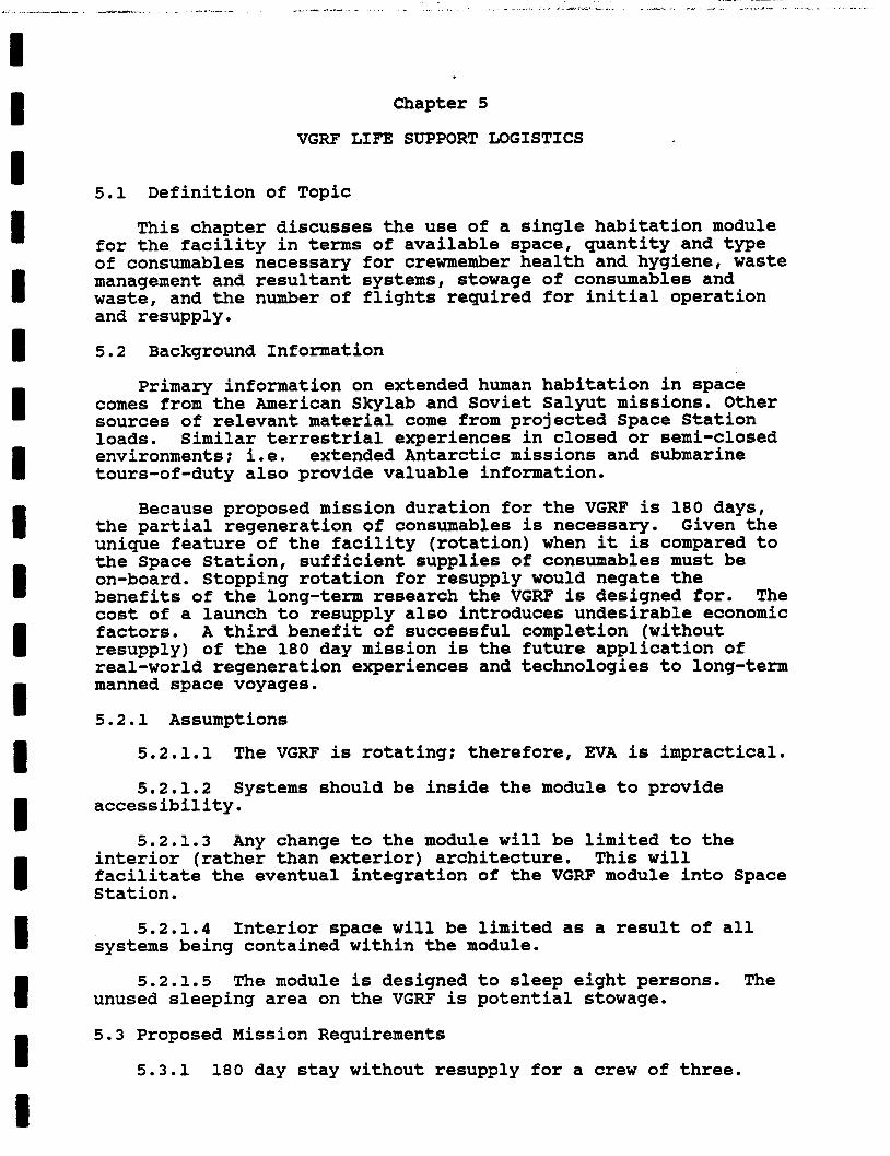
5.1 Definition of Topic
This chapter discusses the use of a single habitation module for the facility in terms of available space, quantity and type of consumables necessary for crewmember health and hygiene, waste management and resultant systems, stowage of consumables and waste, and the number of flights required for initial operation and resupply.
5.2 Background Information
Primary information on extended human habitation in space comes from the American Skylab and Soviet Salyut missions. Other sources of relevant material come from projected Space Station loads. Similar terrestrial experiences in closed or semi-closed environments; i.e. extended Antarctic missions and submarine tours-of-duty also provide valuable information.
Because proposed mission duration for the VGRF is 180 days, the partial regeneration of consumables is necessary. Given the unique feature of the facility (rotation) when it is compared to the Space Station, sufficient supplies of consumables must be on-board. Stopping rotation for resupply would negate the benefits of the long-term research the VGRF is designed for. The cost of a launch to resupply also introduces undesirable economic factors. A third benefit of successful completion (without resupply) of the 180 day mission is the future application of real-world regeneration experiences and technologies to long-term manned space voyages.
5.2.1 Assumptions
5.2.1.1 The VGRF is rotating; therefore, EVA is impractical.
5.2.1.2 accessibility . Systems should be inside the module to provide
5.2.1.3 Any change to the module will be limited to the interior (rather than exterior) architecture. This will facilitate the eventual integration of the VGRF module into Space Station.
5.2.1.4 Interior space will be limited as a result of all systems being contained within the module.
5.2.1.5 The module is designed to sleep eight persons. The unused sleeping area on the VGRF is potential stowage.
5.3 Proposed Mission Requirements
5.3.1 180 day stay without resupply for a crew of three.
I I B B B I B I I I B I B I I I I 1
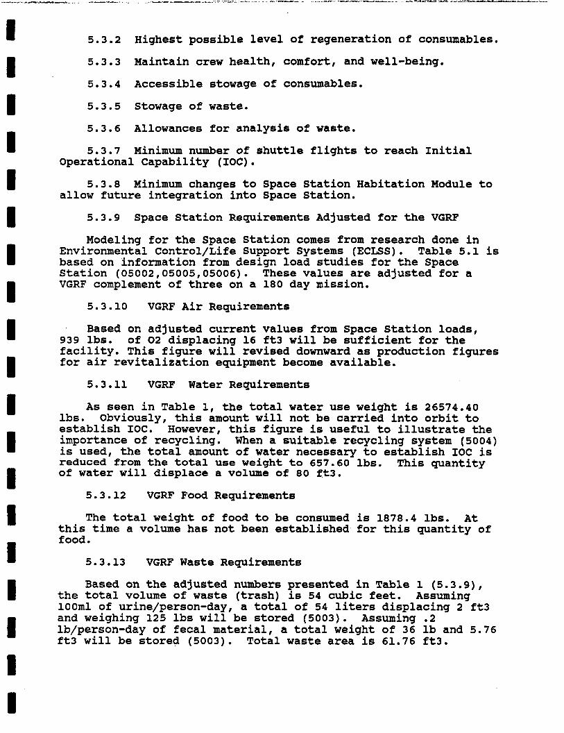
5.3.2 Highest possible level of regeneration of consumables.
5.3.3 Maintain crew health, comfort, and well-being.
5.3.4 Accessible stowage of consumables.
5.3.5 Stowage of waste.
5.3.6 Allowances for analysis of waste.
5.3.7 Minimum number of shuttle flights to reach Initial Operational Capability (IOC).
5.3.8 allow future integration into Space Station.
Minimum changes to Space Station Habitation Module to
5.3.9 Space Station Requirements Adjusted for the VGRF
Modeling for the Space Station comes from research done in Environmental Control/Life Support Systems (ECLSS). Table 5.1 is based on information from design load studies for the Space Station (05002,05005,05006). These values are adjusted for a VGRF complement of three on a 180 day mission.
5.3.10 VGRF Air Requirements
Based on adjusted current values from Space Station loads, 939 lbs. of 02-displacing 16 ft3 will be sufficient for the - facility. This figure will revised downward as production figures for air revitalization equipment become available.
5.3.11 VGRF Water Requirements
As seen in Table 1, the total water use weight is 26574.40 Obviously, this amount will not be carried into orbit to lbs.
establish IOC. However, this figure is useful to illustrate the importance of recycling. When a suitable recycling system (5004) is used, the total amount of water necessary to establish IOC is reduced from the total use weight to 657.60 lbs. of water will displace a volume of 80 ft3.
This quantity
5.3.12 VGRF Food Requirements
The total weight of food to be consumed is 1878.4 lbs. At this time a volume has not been established for this quantity of food .
5.3.13 VGRF Waste Requirements
Based on the adjusted numbers presented in Table 1 (5.3.9), the total volume of waste (trash) is 54 cubic feet. Assuming lOOml of urine/person-day, a total of 54 liters displacing 2 ft3 and weighing 125 lbs will be stored (5003). Assuming .2 lb/person-day of fecal material, a total weight of 36 lb and 5.76 ft3 will be stored (5003). Total waste area is 61.76 ft3.

I I I I I I I I I I I I I I I I I I I
5.4 Proposed Method of Meeting Mission Requirements
The life support system for the VGRF will be an integral part Because of this, on board stowage will
Assuming of the Habitation Module. be a major factor in the feasibility of the VGRF. sufficient area has been allocated for the stowage of air, food, and water in the module, VGRF concerns must address the stowage of waste. under 100 ft3. Since the crew complement of the VGRF is three, five sleeping areas, each with a volume of 150 ft3, are available as stowage areas (5001). Initial research indicates that sufficient area is available on-board the module to meet the requirements outlined in this report.
As seen in 5.3.13, preliminary figures on waste are
5.5 Alternative Methods of Meeting Mission Requirements
5.5.1 The addition of a node would increase the available space for stowage and living space. However, this would result in a substantial weight penalty.
5.6 Discussion of Unresolved Issues
At this time, the actual number of flights necessary to reach IOC is unresolved because all systems on board the VGRF have not been identified and given weight/volume values. Until all system values are known, computations cannot be carried out. However, based on information presented this semester in the Space Studies 305 class and given. the present payload capacity of the shuttle, it is unlikely that the VGRF can be in place after only one shuttle flight. All weight/volume values for on-board systems and personal items will have to identified.
5.7 Summary
As a result of this research, a major issue of the VGRF facility has been dealt with: Can the mission be accomplished with one Habitation Module? The preliminary research of this paper shows that sufficient capacity is apparently available in the module to allow the necessary life support systems and stowage of consumables and waste.
5.8 References
05001 Space Station Program Off ice . 1987. Baseline configuration document, JSC 30000. 1-1 to 5-2 p. Houston, TX: NASA.
05002 Space Station Program Office. 1987. Space station systems requirements, JSC 30000 Sec. 3 Rev. D. 1-1 to 4-2 p. Houston, TX: NASA.
05003 Parker, R.B. 1987. Personal interviews. Fall semester. University of North Dakota: Space Studies.
I I I I I 1 I I I I 1 I 1 I I I I I
05004 Schubert, F.H., R.A. Wyneen, and P.D. Quattrone. 1985. Advanced regenerative environmental control and life support systems: air and water regeneration. In: Controlled ecological life support system: life support systems in space travel. NASA Conference Publication 2378, 29-38 p. Houston,TX: NASA.
05005 Slavin, T.JOt F.A. Leining, and M.W. Oleson. 1986. CELSS waste management systems evaluation. In: Aerospace environmental systems: proceedings of the sixteenth ICES conference - P-177, 775-790 p. Warrendale, PA: Society of Automotive Engineers, Inc.
05006 Prejean, Stephen E., and Cletis R. Booher. 1986. Space station personal hygiene study. In: Aerospace environmental systems: proceedings of the sixteenth ICES conference - P-177, p. Warrendale, PA: Society of Automotive Engineers, Inc.

I I I I I I I I 1 I I I I I I I I I I
TABLE 5.1 VGRF Design Average Loads
Space Station Values Three person/ 180 Day Totals
~ ~ ~ ~ ~ ~ o ~ o o I - - - - ~ o o o o o o o o ~ ~ ~ ~ ~ p ~ ~ ~ ~ o o o o ~ o ~ o o o o o o ~ ~ ~ ~ o o o o ~ ~ ~ ~ o o
Metabolic 02 1.84 lb/person-day 993.60 lb
Module 02 Leakage 95.00 lb/180 day mission 95.00 lb
Airlock Losses 46.00 lb/180 day mission 46.00 lb
Atmosphere Totals . 1134.60 lb
~ ~ ~ ~ ~ ~ 0 0 0 0 0 0 ~ ~ ~ ~ 0 0 0 0 0 ~ 0 ~ ~ 0 0 ~ ~ ~ ~ ~ ~ ~ ~ ~ ~ o ~ o o o ~ ~ ~ ~ o ~ ~ ~ ~ o o o ~ ~ ~ ~ ~ ~ ~
Drinking H20 2.86 lb/person-day 1544.40 lb
Food Preparation H20 3.90 lb/person-day 2106.00 lb
Clothing Wash H20 27.50 lb/person-day 14850.00 lb
Hand Wash H20 7.00 lb/person-day 3700.00 lb
Dish Wash H20 2.00 lb/person-day 1080.00 lb
Shower H20 5.00 lb/person-day 2700.00 lb
Urinal Flush H20 1.10 lb/person-day 594.00 lb
H20 Use Total 26574.40 lb
- - ~ ~ - - ~ ~ ~ ~ - - - ~ o ~ ~ ~ o o o ~ ~ ~ o ~ Foodoo----ooo--ooo--oo---oooo-oo-o
Food Solids 1.36 lb/person-day 734.40 lb
Food H20 1.10 lb/person-day 594.00 lb
Food Packaging 1.00 lb/person-day 540.00 lb
Food Total Weight 3.46 lb/person-day 1878.40 lb
- - - o o o - ~ - ~ ~ ~ - ~ ~ ~ o o ~ ~ o ~ ~ ~ o ~ ~ ~ ~ ~ ~ o ~ o ~ o o ~ ~ ~ ~ ~ ~ ~ o o ~ ~ ~ ~ o ~ ~ ~ o ~ ~ ~
Trash Solids 1.80 lb/person-day 972.00 lb
Trash H20 .30 lb/person-day 167.00 lb
Trash Total Weight 2.10 lb/person-day 1139.00 lb
Trash Volume (ft3) O.lO/person-day 54.00
6.1
Chapter 6
SOLUTIONS TO POSSIBLE EMERGENCIES ABOARD THE VGRF
Definition of Topic
This chapter deals with possible emergency situations that would be unique to the Variable Gravity Research Facility(VGRF).
6.2 Background Information
Because the VGRF is a closed system that rotates, a major malfunction inside the HM or a change in the rotational physics could severely disable or even destroy the entire structure. The ideas introduced are not intended to cover all space-bound emergencies, but those emergencies that would be unique to the VGRF. Being that the VGRF system is a relatively inexpensive space project, certain concessions in terms of complexity and weight must be made. By using some, if not all of the ideas introduced, the maximum safety for the crew could be provided at the lowest cost possible for adequate protection of the VGRF project. Issues that should be looked at include:
1) Tether failure 2) Atmosphere contamination due to fire/smoke 3 ) Potential "safe areas" 4) Use of a Crew Emergency Return Vehicle (CERV)
6.3 Proposed Mission Requirements
System requirements would include:
1) Tethers used between the external tank(ET) and habitation module(HM) should be able to maintain structural integrity in the event they are impacted by micrometeorites and/or other space debris.
2) Fire/smoke containment systems should include the use of airtight bulkheads in order to separate crewmembers from fires and to keep from contaminating the entire HM.
"safe areas" to provide close protection to the crew in the event of an emergency.
3) Several locations within the HM should be designated as
4) A CERV should be implemented to be used as a possible safe area, or to leave the VGRF if a major system malfunction or medical emergency were to occur.
6.4 Proposed Method of Meeting Mission Requirements
6.4.0.1
By using two tethers on each end instead of one, the system could insure that the severing of a tether would not jeopardize the crew and the structure. Constructing the tethers into a
I 1 I I I I I P I I I I I I
ribbon structure (thin and wide) rather than having a circular structure reduces the chance of damage due to typical micrometeorite impact.
6.4.0.2
The fire and smoke containment systems should have the ability to close off sections of the HM to separate crewmembers from the flames and gases. bulkhead running from the ceiling to the floor, with a door that would be opened for normal operations, or sealed in the event of an emergency.
The HM should be fitted with an airtight
6.4.0.3
The proposed safe-areas on the VGRF should be located in the CERV, the resource node, and on either side of the airtight bulkhead. Emergency supplies stored at each area would include one full pressure or partial pressure suit (06001, p.398), two portable rescue balls, and an emergency medical kit. Emergency supplies stored in each half of the HM would include:
1) Pressure suits--2 2) Rescue balls-4 3) Emergency medical kits--2
6.4.0.4
The use of a CERV on the VGRF is the only sure way to provide the greatest amount of safety to the crew. Because the VGRF will be using the habitation module of the Space Station, the escape capsule selected for Station would most likely be used for the VGRF. Presently, NASA is looking at three different designs for an escape module(06006, p.30), while the British are also looking into contributing a CERV(06005, p.9). All current designs could provide more than adequate space for the VGRF crews, and few or no modifications would be required if the capsule were to be used.
6.4.1 Discussion of Proposed Method
6.4.1.1
Tethers: Advantages
-If a single tether on one end were to be severed or to fail, the other tether would be able to support the structure until repairs could be made.
inside both HM and ET.
I -Four tethers could provide better stability to loads imposed
Disadvantages
-Would increase cost and weight of the system.
-Would add complexity to the installation of the tether system. capsule were to fail, a rope-ladder system could be lowered by
Even if both tethers at the end opposite of the escape 1
accessing controls at the other end of the capsule. crewmembers were injured, a winch type system could be implemented like that used for helicopter rescue systems to lift the individuals up to the CERV. In using a four tether system, the severing of one tether would not seriously jeopardize the mission. installation, lower cost, and reduced complexity, but places the VGRF crew and structure in danger if one of the tethers were to fail.
If
The single tether system has advantages of easier
6.4.1.2
Fire/Smoke Containment: Advantages
contaminated areas of the HM. -Would provide separation between crewmembers and the
- Prevents the entire HM from being contaminated with dangerous gases, smoke, heat, and flames.
-Makes it possible to extinguish a serious fire by enclosing it, and exposing it to vacuum, without endangering the crew.
Disadvantages
-Would have greater cost and complexity due to the need to install airtight bulkheads in the module.
-May cause difficulty if a certain system is cut off from the crew
-Crew would not have access to full oxygen and water supplies.
Since the VGRF is a closed system, any appreciable loss of cabin atmosphere would be disasterous to the mission. In order to prevent total contamination of the HM it must be required that the VGRF have the ability to close off areas of contaminated atmosphere from the rest of the module. If the HM were to have an airtight bulkhead down the center, only half the atmosphere would be exposed. cabin, only a partial amount would be required. With the ability to seal off a section of the HM it would also be possible to evacuate the area to either extinauish the fire, or
So instead of needing to replenish the entire
- to vent the contaminants to vacumm.
6.4.1.3
Safe Areas: Advantages
emergency. -Would provide close, immediate support to crewmembers in an
-Could be a source for emergency supplies if a crisis were to occur.
-Would give immediate access to space suits or rescue balls if decompression were to occur.
__
Disadvantages
-Would increase costs due to.redundancy of supplies.
-May take up habitable living areas.
Because the HM will have a resource node attached at one end and an escape capsule at the other, these two separate structures could be designated as safe areas. If the structure were low on oxygen, one crewmember could don a pressure suit while the other two members could get into their respective rescue balls and use internal oxygen until the crewmember in the pressure suit could transfer the others into the CERV for return to Earth. These rescue balls should be located in the resource node as well as in each half of the HM to provide redundancy. If no safe areas are designated or pressure suits provided, the crew faces the possibility of explosive decompression without the benefit of back-up oxygen supplies.
6 . 4 . 1 . 4
Escape Capsule: Advantages
-Would provide immediate escape for crew in the event of a major system breakdown.
-Crew would not have to depend upon the Space Shuttle for a
-Makes possible the immediate return to Earth of seriously
rescue.
ill or injured crewmembers.
Disadvantages
-Increase cost and weight, and complexity to the VGRF
-May increase the number of Shuttle missions required in order to attach the escape module to the HM.
Because the VGRF is a self-maintaining system, any loss of a major system(1ife support) could terminate the mission. In order to provide the crew with a fast return to Earth, an escape capsule must be provided. different alternatives for an escape vehicle for the Space Station.
Presently NASA is looking into three
The first is a winged vehicle which would have the ability for flying reentries and lower gravity loading. able to land at a wider range of sites. this system would be the added cost and complexity as opposed to a capsule designed for parachute landings in the water.
It would also be The disadvantage of
The second NASA suggestion is a lifting capsule similar to those used as the Apollo command modules(CM). Because the VGRF is only a three person crew it would work best for the project. NASA has looked at refurbishing CMIs that exist in museums around the country. The only problem with using the old CMIs is that they were only originally designed to operate at 5psi as opposed to 14.7psi being used on the Space Station. Either the

CM has to be stressed further, or a similar system for use on the VGRF and Space Station.
A third option being looked at is a ballistic capsule shaped like the earlier Discover vehicles. This system would be the least costly to develop but would have the disadvantage of high g loads on the crew(up to 8).(06006, p.30) The British are also developing a CERV that could hold up to 6 passengers. capsule includes control thrusters, hygiene and galley facilities, air tank, and even a payload bay. It would splash down much like a CM. (06005, p.9)
This
6.4.2 Weight Estimate of Proposed Method
If the VGRF is fitted with an Apollo series command module for the escape capsule the weight of the module would be 12,500 pounds(06008, p.363). Presently NASA is in phase B/phase C studies of three different types of crew escape vehicles and no specific weight has yet been given(06006, p.30). If the VGRF program adopts a British built CERV, the weight would be about 14,000 pounds (06005,p.g) . Weight for three emergency medical kits will be 18 pounds(06007,p.4.8).
6.5 Alternate Methods of Meeting Mission Requirements
6.5.1 Tethers
One alternative method for the tethering system would be to have only a single tether at each end. expensive system to design and would be easier to install while in orbit. By only having a single tether system, the failure of a tether would lead to the end of the VGRF mission and warrant immediate departure of the crew.
This would be a less
Another alternate method for the tether system would be to weave the Kevlar material into a thin ribbon instead of the proposed cable design. were to impact the ribbon, only a small hole would be formed in the material which would not cause failure of the entire structure.
If a micrometeorite or other such space debris
6.5.2 Fire Containment and Safe Areas
If there was no pressurized bulkhead in the center of the HM the installation and redesign costs of the VGRF would be lowered. However, if a pressurized bulkhead is not used, a fire, or contamination of the cabin atmosphere would leave the crew susceptible to harm if they could not reach either the resource node at one end, or the CERV at the other. Without the bulkhead the entire HM would be open to damage from the fire as well as contamination from smoke and gases.
Another method would be to provide multiple bulkheads along the length of the HM but this added redundancy could impede rather than aid an emergency by creating more obstacles between the crewmembers. Another disadvantage to this is that these bulkheads would cut down on the habitable area available to the
crew. Also, the cost system would rule out
and complexity for installation of this this alternative as impractical.
6.5.3 Escape Capsule
The only alternative in dealing with the CERV'is not to have one on the VGRF. lowered and no further research or development would be required for the CERV on the VGRF. escape capsule the crew would have to depend upon the Space Shuttle and/or internal emergency systems in the event of a crisis situation.
By not having a CERV the launch costs would be
If the VGRF were to go without an
6.7 Summary
All of the ideas introduced in this section of the report report have taken into account the safety issues that are unique to the VGRF crew and structure. Originally, the structure was to have a two-tether system but in order to provide redundancy, a four tether system was suggested. To enhance safety of the crew from fire or contaminants of the atmosphere, a pressurized bulkhead running from the ceiling to the floor is suggested. emergency supplies are to be stored at each end of the HM in the event that either half needs to be evacuated. Also the need for a CERV was suggested in order for the crew to depart the VGRF structure in the event of a major malfunction or the injury of a crewmember.
Extra
6.8 References
06001
06002
06003
06004
06005
06006
06007
06008
06009
Chernykov, I.N. 1975. Foundations of space biology and medicine. Info. Office.
Chein, P. 1987. Assembling the space station. Space World x-12-288: 16-20.
Kofler, L. 1987. Shuttle escape system. Space World X-11-287: 8.
Lorenz, R. 1988. Debris hazard poses future threat. Spaceflight 30(1): 4-7.
Anonymous. 1988. UK plan for space rescue capsule. Spaceflight 30(1): 9.
Covault, C. 1987. NASA to seek design concepts for station crew escape vehicle. Techno1 127(7) :30.
Aviation Week and Space
Joels, K.M. 1982. The space shuttle operators manual. 154p. New York: Ballentine Books.
Collins, M. 1974. Carrying the fire. 478p. Toronto: Doubleday Canada, Ltd.
Eagon, M. 1987. Assembly of a variable gravity research facility, Ch. 2. In no editor. Varible gravity research facility: fall semester 1987 class report. Grand Forks, ND: Space Studies Program.
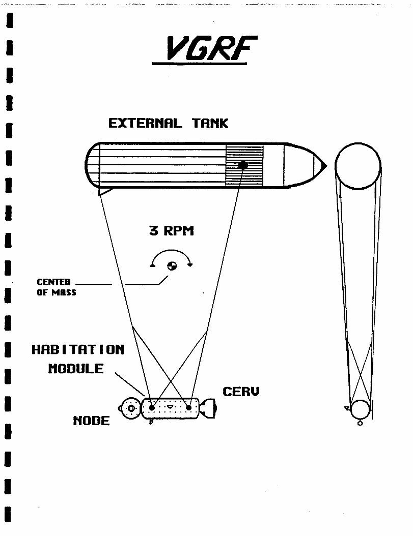
I li I
VGR!!
EXTERNAL TCINK
3 RPM
CENTER OF MASS
HABITATION MODULE
NODE U
CERU
7.1
Chapter 7
ANTENNAE SOURCES AND COMMUNICATIONS
Definition of Topic
This chapter presents the options for antenna use and communications on the Variable Gravity Research Facility.
7.2 Background Infomation
Communication between the VGRF and NASA Mission Control, as well as the Shuttle, is essential. This communication will be dependent on the VGRF's antenna correspondence with satellites and other antenna sources. Antennae design must take into account the rotation of the VGRF. antennae with related satellites and antennae receptors may pose the problem of obscuration.
The alignment of the VGRF
The International Space Station is planned with the
a. Global Positioning System Antenna
following type of antennae:
A single conical spiral or cavity back disk type antenna is used (07001 p 46). GPS satellites have polar orbits, different from the low earth orbit (LEO) of the VGRF. The VGRF, for navigational purposes, needs to receive signals from any four satellites at one time to determine its position. Therefore, a GPS antenna is required.
b. Tracking and Data Relay/Acquisition satellite
The multiple-feed antenna. commands and television (07003 p 5).
TDRS/TDRA antenna is a steerable single reflector It is a prime data-relay satellite for
C. Shuttle Antenna
A Shuttle compatible antenna is necessary for docking with the VGRF. A phased-array type communications antennae will be required for communication between the Shuttle and the VGRF. (07003 p 4-13).
d. Multiple Access Link Antennae
A multiple access link antenna is used to communicate with other vehicles (i.e. free-flying satellites which may project radio signals to Earth) and uses a multiple-phased array allowing 10 or more users. antennae that apply to MA antenna use depending on long-range of proximity of use (07002 p 4-16). The MA link antenna services designated degree quadrants (i.e. 30 degree or 60 degree segments) .
There are low gain and high gain
7.3 Proposed Mission Requirements
The antenna placement requires the consideration of all the necessary antennae including the GPS antenna, TDRS/TDRA, Shuttle and MA antennna. For optimal communication duration, the location of the antennae on the spinning VGRF in relation to the sub-satellites, Earth and other correspondence devices is of great importance.
7.4
Tank (ET) will pose some difficulty with antennae obscuration. Placement should take into account the following:
High and low gain multiple beam phased array antenna aimed in service quadrants (07002 2.0). This may be accomplished by extending rotating antennae booms to service these quadrants on the VGRF (07001 fig. 24).
Proposed Method of Meeting Mission Requirements
The VGRF's spinning Habitation Module (HM) and External
1.
2. Multiple antennae location on the VGRF to work in conjunction with GPS, free flyers, platforms and sub-satellite systems. be used in conjunction with antennae booms.
Multiple locations directly located on the VGRF could
3. TDRS antenna must be stabilized to accomodate the "steering" factor of the antenna (07001 p 2-6). a center of gravity location would be best on the VGRF.
7.4.1 Discussion of Proposed Method
For this reason,
The multiple beam array and multiple access link antennae pose a disadvantage in the great number of antennae that must be located on the VGRF to service the quadrants in space. Coverage of these quadrants is necessary to provide the advantage of short distance communication with the equipment module units, Shuttle, and free flyers (07002 3.0). An advantage is the directive beam steering which allows adjustment of the service quadrant (07006 p 4).
Rotating boom extensions could be used to optimize antennae placement and to help minimize obscuration. Booms may be used by the GPS antennae. Simultaneous one-way communication from any four GPS satellites is required for navigational purposes (07001 p 2-3). An advantage to extending booms for GPS antennae is that there may be a periodic check with ground telemetry and daily parameters may be located if necessary (07005 p 4-1). GPS satellites have their own orbit and do not share that orbit with other objects. If a user vehicle is directly beneath one of the satellites, a very broad antenna beam width would be required to capture any signals (07001 p 4-13).
Sub-satellite systems such as free flyers, platforms, and multi-beam antennae provide relay satellite service and omni-encompassing coverage. However, they also require strict resolution requirements, so obscuration could occur if alignment is not precise (07001 p 2-6).

The Tracking and Data Relay Satellite (TDRS) system is the prime GEO satellite for communications (07001 p 2-6). A steerable single multiple feed antenna is sufficient for coverage (07002 3.5). This relay satellite links with the ground and will transfer voice, video, telemetry, text and graphics and also provides the ability to direct to other TDRS satellites (07001 p 2-6). A disadvantage here may be its necessity to have stable placement (07007 p 812). The center of gravity location would provide the stablization necessary for the TDRS antenna.
7.4.2 Weight Estimate of Proposed Method
Weight estimates for antennae vary with the number of antennae configurations on the VGRF. one communications antenna (with reflector, booms(2), and band reflectors) ranges from 214 lbs. to 448 lbs. (07012 p 4-71). This weight is dependent on the antenna aperture (opening) and is without transponder or transponder feed assembly weight added to it. With this added weight, the entire configuration could vary from approximately 535 lbs. to 890 lbs. per antenna (07012 p 4-71). Very small receptor antennae on the VGRF would have significantly smaller weight estimates.
The approximate weight of
7.5 Alternate Methods of Meeting Mission Requirements
7.5.1 First Alternative
A tracking antenna on the VGRF, compatible with the TDRS system, would provide the link for communication and data transfer. An antenna would also be required for docking with the shuttle. telemetry and communications needs for the VGRF. The disadvantage of this alternative is that the cost associated with ground based guidance and navigation is higher due to the required ground personnel. the GPS for guidance and navigation would be more cost effective, but would result in additional weight and complexity in the form of an extra antenna.
This alternative would provide the necessary basic
Using a space-based system such as
7.5.2 Second Alternative
A second alternative is the use of a retractable antenna on the VGRF. Due to the maneuverability of this antenna, it would be of use in serving the quadrants for the MA antennae. The antenna may be unfurled and retracted from the VGRF as necessary to service these quadrants while the VGRF is in rotation (07010). service the quadrants at random or as necessary. Disadvantages may be that the deployment may hinder the VGRF, be clumsy and possibly produce significant drag factors.
An advantage to this system is the ability to
7.5.3 Third Alternative
A third alternative is the use of a VGRF flight-synchronized free flyer located in direct proximity to the VGRF. The free flyer would act as an antennae base to transmit directly to and from the antennae on the VGRF (07011). advantage to this alternative would be continous communication between the VGRF and GPS, TDRS or other sub-satellite systems.
An
The major disadvantage to this alternative is the cost of launching the extra satellite.
7.5.4 Fourth Alternative
Another alternative for consideration is the elimination of the GPS and Shuttle antennae in communication options. TDRS/TDRA satellite and antennae, as well as the multiple access link antenna. However, the benefits of keeping the GPS and Shuttle antennae are numerous and should not be dismissed without considerable thought. benefits and the Shuttle antennae offers communication advantages that should not be disregarded.
7.6 Discussion of Unresolved Issues
The VGRF could sustain itself on the use of the
The GPS offers supreme navigational
The alignment of the rotating VGRF in relation to the various satellites may cause obscuration difficulties. This may be minimized by using the respective antennae only in line-of-sight positions (07002 2.0).
their respective weights is an issue that must be determined in relation to the other requirements on the VGRF.
The actual number of required (or allowed) antennae and
7.7 Summary
The VGRF needs the communications and telemetry that are provided by the TDRS/TDRA and Shuttle antennae. be mounted directly on the HM, but the TDRS/TDRA antenna will need to be mounted on the side on a short boom so that it can rotate to keep its pointing position.
The Shuttle antenna can
7.8 References
07001 NASA. 1983. Communications, tracking and navigation systems. II., ch. 13. Space station study RF coverage analysis. Pages unnumbered. Johnson Space Center, TX: Lyndon B. Johnson Space Center.
Evolutionary space station, vol. V, pt.
07002 NASA. 1983. Communications, tracking and navigation systems. Evolutionary space station, vol. V, pt. l., ch. 8. Space station study RF coverage analysis. Pages unnumbered. Johnson Space Center, TX: Lyndon B. Johonson Space Center.
07003 NASA. 1983. Communications, Tracking and navigation systems. II., ch. 12. Space station study RF coverage analysis. Pages unnumbered. Johnson Space Center, TX: Lyndon B. Johnson Space Center.
Evolutionary space station, vol. V, pt.
07004 Anonymous. 1986. Antennas required, ch. 4. In no editor. Variable gravity research facility: fall semester class report. Grand Forks, ND: Space Studies Program. University of North Dakota.
07005
07006
07007
07008
07009
07010
07011
07012
NASA. 1983. Communications, tracking and navigation systems. Evolutionary space station , vol. V, pt. 11, ch. 1. Space station study RF coverage analysis. Pages unnumbered. Johnson Space Center,TX: Lyndon B. Johnson Space Center.
NASA. 1983. Communications, tracking and navigation systems. Evolutionary space station, vol. V, pt. 11, ch. 1. Space station study RF coverage analysis. Pages unnumbered. Johnson Space Center, TX: Lyndon B. Johnson Space Center.
NASA. 1984. Space-based antenna measurement system concepts for space station operation. Space antenna systems. 484 p. NASI. 55:2368-ptO-2. N85-23840. (NASA CP 2368, pt. 2) CG.
Priebe, r. 1988. Space Studies Program. University of North Dakota. Class discussion.
Parker, R.B. 1988. Space Studies Program. University of North Dakota. Class lecture.
Kelly, D. 1988. Space Studies Program. University of North Dakota. Class discussion.
Parker, R.B. 1988. Space Studies Program. University of North Dakota. Personal interview.
NASA. 1985. Spacecraft (mobile satellite) configuration design study. Final report. N85-34152. (NASA-CR-176153).
Chapter 8
USES OF RESIDUAL FUEL FROM
8.1 Definition of Topic
Not all of the fuel in the External Tank (ET) of the Space Shuttle is consumed by the time the vehicle is brought into orbit. Residual liquid hydrogen (LH2) and liquid oxygen (LO2) remain in the tanks. This fuel can be used on board the Variable Gravity Research Facility (VGRF).
8.2 Background Information
The ET has a capacity of 528,616 gallons (2,001,023L) or 1,589.577 pounds (721,032 kg). This breaks down into 143,351 gallons (542,641 L) or 227,641 pounds (103,257 kg) of LH2. (08007) Not all of this fuel is consumed during ascent of the Shuttle. There are three categories of residual fuel. Safety reserves are the planned reserves needed to insure that the tanks do not run dry or develop bubbles in the lines. Three thousand pounds(average) H2 remains in the ET. This fuel may be placed into three categories: 800 pounds H2 gas, 1120 pounds H2 liquid, and approximately 1100 pounds of H2 liquid trapped in tanks, lines, and engines. An average of 5000 pounds of 02 remains. This may be broken into two categories: 2100 pounds of 02 gas and 2800 pounds of 02 liquid trapped in tanks, lines, and engines. (08002 p.8) The second category of residual fuel is flight performance reserve. This accounts for an average of 5520 pounds(approx.) of fuel. The third category of residual fuel is excess because of below-maximum cargo mass. Obviously this varies with each Shuttle flight. The nominal cargo limit is 65,000 pounds. the specific mission and the actual cargo mass is excess fuel. For example, if the cargo on a mission weighs five tons less than the limit for that mission, the excess fuel carried into orbit would be 0.94*5=4.70 tons. (08002 p.9) A t today's launch costs of $5000/kg, millions of dollars could be saved by using the residual fuel from the ET. (08002)
About 94% of the margin between the limit for
8.3 Proposed Mission Requirements
For economic reasons the residual LH2 and LO2 after reaching orbit should be removed from the ET and used for other purposes. The fuel may be used as propulsion for spin-up, to power H2-02 fuel cells, or simply burned to produce water.
8.4 Proposed Method of Meeting Mission Requirements
Unused LH2 and LO2 could power a low-thrust rocket engine such as the RLlO which was used on the Centaur stage of the Atlas-Centaur. (08006) The rocket would provide propulsion for spin-up. A gradual spin-up is desirable for minimal stress on the crew and equipment in the habitation module. Therefore a low-thrust rocket such as the RLlO is ideal.
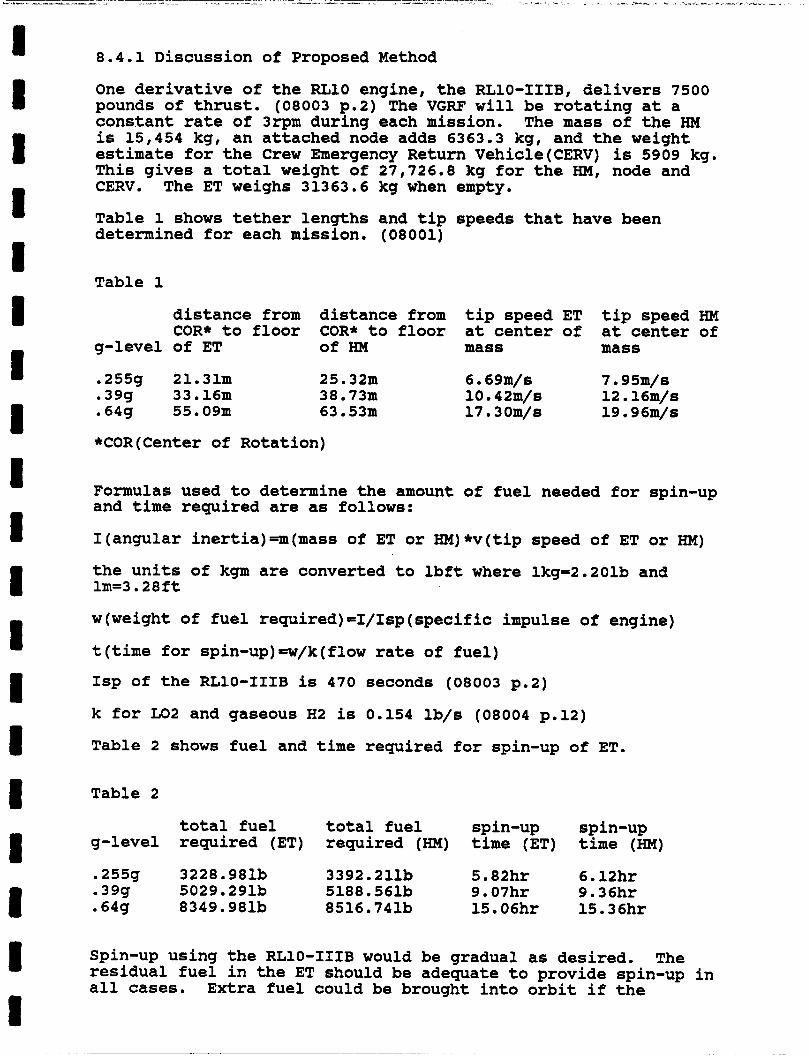
8.4.1 Discussion of Proposed Method
One derivative of the RLlO engine, the RL10-IIIB, delivers 7500 pounds of thrust. (08003 p.2) The VGRF will be rotating at a constant rate of 3rpm during each mission. is 15,454 kg, an attached node adds 6363.3 kg, and the weight estimate for the Crew Emergency Return Vehicle(CERV) is 5909 kg. This gives a total weight of 27,726.8 kg for the HM, node and
The mass of the HM
CERV.- The ET weighs 3i363.6 kg-when
Table 1 shows tether lengths and tip determined for each mission. (08001)
Table 1
g-level
.39g
.255g
.64g
distance from COR* to floor of ET
21.31111 33.16111 55 . 09m
distance from COR* to floor of HM
25.321~ 38.731~ 63 . 53m
empty . speeds that have been
tip speed ET tip speed HM at center of at center of mass mass
6 . 69m/s 10 . 42m/s 12.16m/s 17 . 30m/s 19 . 96m/s
7 . 95m/s
*COR(Center of Rotation)
Formulas used to determine the amount of fuel needed for spin-up and time required are as follows:
I(angu1ar inertia)an(mass of ET or HM)*v(tip speed of ET or HM)
the units of kgm are converted to lbft where lkg=2.201b and lm=3.28ft
w(weight of fuel required)=I/Isp(specific impulse of engine)
t(time for spin-up)=w/k(flow rate of fuel)
Isp of the RL10-IIIB is 470 seconds (08003 p.2)
k for LO2 and gaseous H2 is 0.154 lb/s (08004 p.12)
Table 2 shows fuel and time required for spin-up of ET.
Table 2
total fuel total fuel spin-up spin-up g-level required (ET) required (HM) time (ET) time (HM)
.255g 3228.981b 3392.211b 5 . 82hr 6.12hr . 39g 5029.291b 5188 . 561b 9.07hr 9 . 36hr
.64g 8349.981b 8516 . 741b 15 . 06hr 15.36hr
Spin-up using the RL10-IIIB would be gradual as desired. residual fuel in the ET should be adequate to provide spin-up in all cases.
The
Extra fuel could be brought into orbit if the
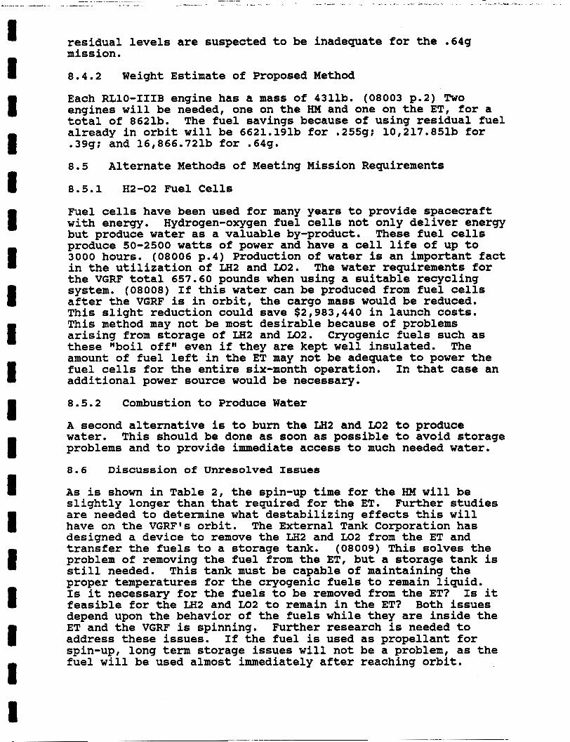
residual levels are suspected to be inadequate for the .64g mission.
8.4.2 Weight Estimate of Proposed Method
Each RL10-IIIB engine has a mass of 4311b. (08003 p.2) Two engines will be needed, one on the HM and one on the ET, for a total of 8621b. The fuel savings because of using residual fuel already in orbit will be 6621.191b for -25511: 10,217.851b for .39g; and 16,866.721b for .64g.
8.5 Alternate Methods of Meeting Mission Requirements
8.5.1 H2-02 Fuel Cells
Fuel cells have been used for many years to provide spacecraft with energy. Hydrogen-oxygen fuel cells not only deliver energy but produce water as a valuable by-product. These fuel cells produce 50-2500 watts of power and have a cell life of up to 3000 hours. (08006 p.4) Production of water is an important fact in the utilization of LH2 and LO2. the VGRF total 657.60 pounds when using a suitable recycling system. (08008) If this water can be produced from fuel cells after the VGRF is in orbit, the cargo mass would be reduced. This slight reduction could save $2,983,440 in launch costs. This method may not be most desirable because of problems arising from storage of LH2 and LO2. these "boil off" even if they are kept well insulated. The amount of fuel left in the ET may not be adequate to power the fuel cells for the entire six-month operation. In that case an additional power source would be necessary.
8.5.2 Combustion to Produce Water
A second alternative is to burn the LH2 and LO2 to produce water. problems and to provide immediate access to much needed water.
8.6 Discussion of Unresolved Issues
The water requirements for
Cryogenic fuels such as
This should be done as soon as possible to avoid storage
As is shown in Table 2, the spin-up time for the HM will be slightly longer than that required for the ET. are needed to determine what destabilizing effects this will have on the VGRF's orbit. The External Tank Corporation has designed a device to remove the LH2 and LO2 from the ET and transfer the fuels to a storage tank. problem of removing the fuel from the ET, but a storage tank is still needed. This tank must be capable of maintaining the proper temperatures for the cryogenic fuels to remain liquid. Is it necessary for the fuels to be removed from the ET? Is it feasible for the LH2 and LO2 to remain in the ET? Both issues depend upon the behavior of the fuels while they are inside the ET and the VGRF is spinning. address these issues. If the fuel is used as propellant for spin-up, long term storage issues will not be a problem, as the fuel will be used almost immediately after reaching orbit.
Further studies
(08009) This solves the
Further research is needed to

8.7 Summary
An average of 8000 pounds of LH2 and LO2 remains in the ET after it is brought into orbit. Leaving this residual fuel in the ET would be a waste of money and energy as the fuel can be used for other purposes. could be powered by the cryogenic fuels to provide spin-up. The RL10-IIIB derivative of the RLlO engine can provide 7500 pounds of thrust. This will be adequate for spin-up while it adds only 8621b to the total weight.
A low-thrust rocket engine such as the RL-10
8.8 References
08001 Allan, S. 1988. Tether lengths and rotation variable speeds for gravity research facility, Ch. 9. In no editor. Variable gravity research facility: spring semester class report. Grand Forks, ND: Space Studies Program, University of North Dakota.
08002 California Space Institute. 1984. A proposal to study possible alternative, accessible supplies of water and other important volatiles for life-science and life-support in orbit. 12p. LaJolla, CA: University of California.
10 p. West Palm Beach, FL: Pratt and Whitney Engineering Division.
08003 Foust, R.R. 1985. RLlO derivative engines for the OTV.
08004 Kmiec, D.C. 1987. High heat transfer oxidizer heat exchanger design and analysis. 80 p. Pratt and Whitney Aircraf t .
08005 Laghari, J.R. 1985. Review of space power technology. Mehran University Research Jour. of Engineering Tehcnol 4 (4) : 29-32 .
08006 Mathis, D.A. 1976. Hydrogen technology for energy. 284 p. Park Ridge, NJ: Noyes Data Corporation.
08007 NASA. 1983. The lightweight space shuttle external tank. NASA Fact Sheet KSC-26-83. Pages unnumbered. Kennedy Space Center, FL: John F. Kennedy Center.
In no editor. Variable gravity research facility: fall semester class report. Grand Forks, ND: Space Studies Program, University of North Dakota.
08008 Nations, J. 1987. VGRF life support logistics, Ch.5.
08009 Parker, R.B. 1988. Space Studies Program. University of North Dakota Personal interviews.
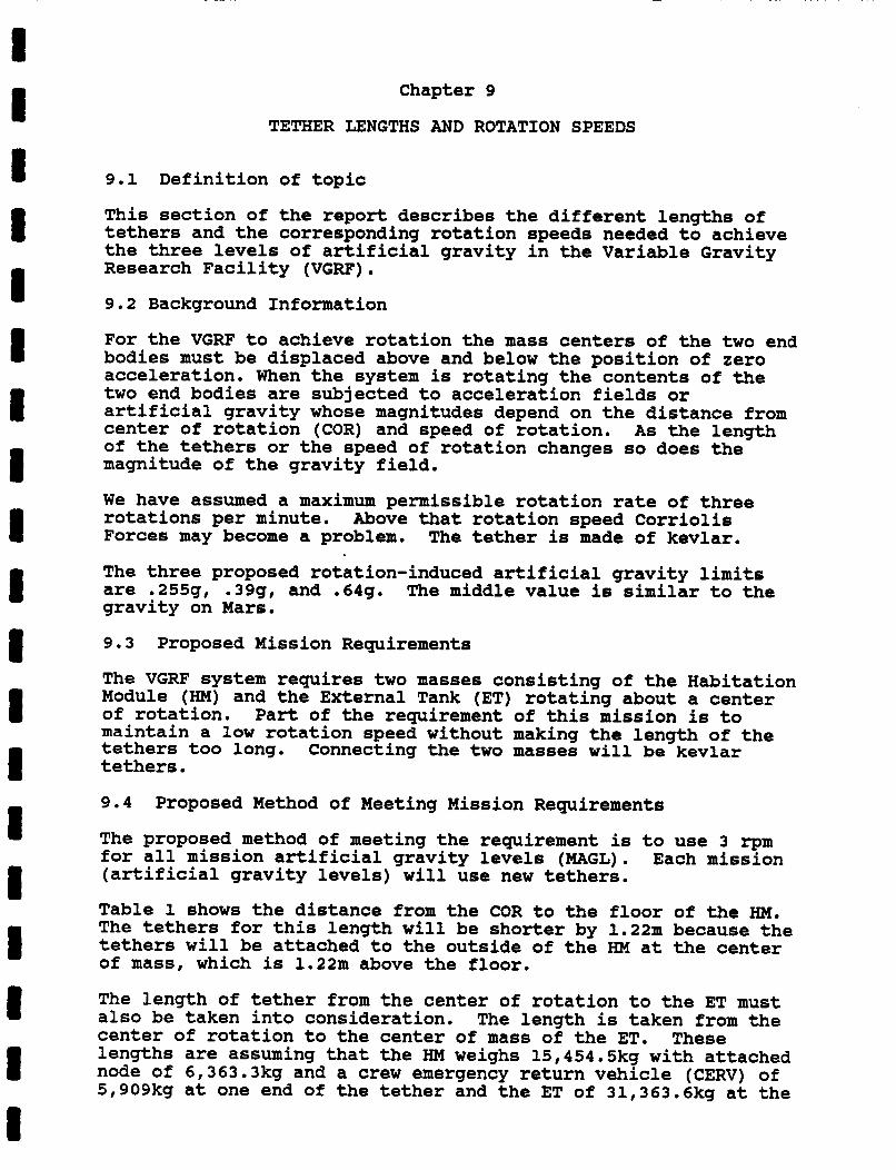
Chapter 9
TETHER LENGTHS AND ROTATION SPEEDS
9.1 Definition of topic
This section of the report describes the different lengths of tethers and the corresponding rotation speeds needed to achieve the three levels of artificial gravity in the Variable Gravity Research Facility (VGRF) . 9.2 Background Information
For the VGRF to achieve rotation the mass centers of the two end bodies must be displaced above and below the position of zero acceleration. When the system is rotating the contents of the two end bodies are subjected to acceleration fields or artificial gravity whose magnitudes depend on the distance from center of rotation (COR) and speed of rotation. As the length of the tethers or the speed of rotation changes so does the magnitude of the gravity field.
We have assumed a maximum permissible rotation rate of three rotations per minute. Forces may become a problem. The tether is made of kevlar.
The three proposed rotation-induced artificial gravity limits are .255g, .39g, and .64g. The middle value is similar to the gravity on Mars.
Above that rotation speed Corriolis
9.3 Proposed Mission Requirements
The VGRF system requires two masses consisting of the Habitation Module (HM) and the External Tank (ET) rotating about a center of rotation. Part of the requirement of this mission is to maintain a low rotation speed without making the length of the tethers too long. Connecting the two masses will be kevlar tethers.
9.4 Proposed Method of Meeting Mission Requirements
The proposed method of meeting the requirement is to use 3 rpm for all mission artificial gravity levels (MAGL). Each mission (artificial gravity levels) will use new tethers.
Table 1 shows the distance from the COR to the floor of the HM. The tethers for this length will be shorter by 1.22m because the tethers will be attached to the outside of the HM at the center of mass, which is 1.22m above the floor.
The length of tether from the center of rotation to the ET must a l so be taken into consideration. The length is taken from the center of rotation to the center of mass of the ET. lengths are assuming that the HM weighs 15,454.5kg with attached node of 6,363.3kg and a crew emergency return vehicle (CERV) of 5,909kg at one end of the tether and the ET of 31,363.6kg at the
These
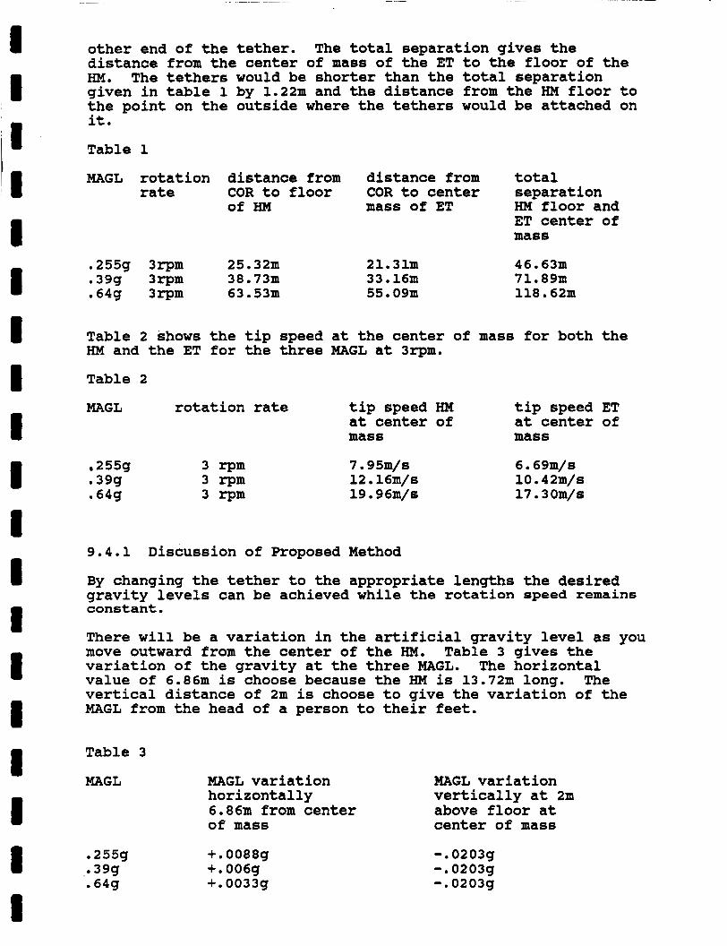
other end of the tether. The total separation gives the distance from the center of mass of the ET to the floor of the HM. The tethers would be shorter than the total separation given in table 1 by 1.22111 and the distance from the HM floor to the point on the outside where the tethers would be attached on it.
Table 1
MAGL rotation distance from distance from total rate
0255g 3rpm .39g 3rpm .64g 3rpm
Table 2 shows HM and the ET
COR to floor COR to center separation of HM mass of ET HM floor and
ET center of mass
25.32m 21.311~ 38.73m 33 . 16m 63.53~1 55.09m
46.63m 71.89m 118.62111
the tip speed at the center of mass for both the for the three MAGL at 3rpm.
Table 2
MAGL rotation rate tip speed HM tip speed ET at center of at center of mass mass
255g 3 r p m .39g 3 r p m .64g 3 r p m
7 . 95m/s 12 . 16m/s 19 . 96m/s
6 . 69m/s 10.42m/s 17.3Om/s
9.4.1 Discussion of Proposed Method
By changing the tether to the appropriate lengths the desired gravity levels can be achieved while the rotation speed remains constant.
There will be a variation in the artificial gravity level as you move outward from the center of the HM. variation of the gravity at the three MAGL. value of 6.86m is choose because the HM is 13.72m long. vertical distance of 2m is choose to give the variation of the MAGL from the head of a person to their feet.
Table 3 gives the The horizontal
The
Table 3
MAGL
.255g
.64g 0 39g
MAGL variation horizontally 6.86m from center of mass
+. 0088g +.006g +. 0033g
MAGL variation vertically at 2m above floor at center of mass
-.0203g -.0203g -. 0203g
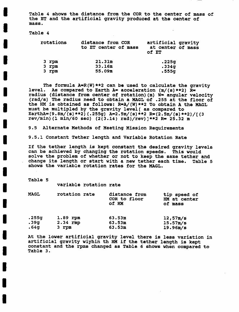
I I I I I I I I I I I I I I I I 1 I I
Table 4 shows the distance from the COR to the center of mass of the ET and the artificial gravity produced at the center of mass . Table 4
rotations distance from COR artificial gravity to ET center of mass at center of mass
of ET
3 r p m 3 r p m 3 r p m
21.31~~ 33 . 16m 55.09m
. 22511 . 334g 555g
The formula A=R(W)**2 can be used to calculate the gravity level. As compared to Earth A= acceleration (m/(s)**2) R= radius (distance from center of rotation)(m) W= angular velocity (rad/s) The radius need to obtain a MAGL of .255 at the floor of the HM is obtained as follows: R=A/(W)**2 To obtain A the MAGL must be multipled by the gravity level( as compared to EarthA= (9 . 8m/ ( 6 ) **2) ( .255g) A=2 . 5m/ ( 8 ) **2 R=(2 . 5m/ ( 6 ) **2)/ [ (3 rev/min) (1 min/60 sec) (2{3.14} rad}/rev)]**2 R= 25.32 m
9.5 Alternate Methods of Meeting Mission Requirements
9.5.1 Constant Tether length and Variable Rotation Rate
If the tether length is kept constant the desired gravity levels can be achieved by changing the rotation speeds. solve the problem of whether or not to keep the same tether and change its length or start with a new tether each time. Table 5 shows the variable rotation rates for the MAGL.
This would
Table 5 variable rotation rate
MAGL rotation rate distance from tip speed of COR to floor HM at center of HM of mass
.255g 1.89 r p m
.39g 2.34 rmp
.64g 3 r p m
63 . 53m 63.531~ 63.53m
12,57m/s 15 57m/s 19 . 96m/s
At the lower artificial gravity level there is less variation in artificial gravity wiyhin th HM if the tether length is kept constant and the r p m s changed as Table 6 shows when compared to Table 3.
I I I I I I I I I I I I I I I I I I I
Table 6
MAGL MAGL variation horizontally 6.86m from center of mass
.255g +.0004g
.39g +.0015g
.64g +. 0035g
MAGL variation vertically at 2m above floor at center of mass
- 0 0091g -.0130g -.0203g
9.5.2 The Same Tether for All 3 MAGL
Keeping the same tether and shortening it would save on tether cost. It needs to be known if the same tethers can withstand three different missions or if it will be necessary to replace them because of deterioration.
Replacing the tethers after each mission will probably be the best plan. keep the same tether during de-spin it would have to stay attached to the HM, but the tether might flap when the HM is separated from the ET causing damage to the external structures.
There is the chance of tethers being weakened. To
9.7 Summary
The required gravity levels will be produced by the rotation of the HM and ET about their center of gravity with tethers connecting them. The three levels (.255g, .39g, .64g) of artificial gravity can be achieved by using the tethers of 25.32m, 38.73m, 63.53m.
9.8
09001
09001
09002
09003
09004
References
Lamo, A.C. 1986.0 Cable tether system, Ch. 4, 7 p. In no editor. Varible gravity research facility: fall semester 1987 class report. Grand Forks, ND: Space Studies Program, University of North Dakota.
Lamo, A.C. 1986.0 Cable tether system, Ch. 4, 7 p. In no editor. Varible gravity research facility: fall semester 1987 class report. Grand Forks, ND: Space Studies Program, University of North Dakota.
Lundquist, C.A. 1985. Artificial or variable gravity attianed by tether systems. 8 p. The University of Alabama in Huntsville.
Baracat, W.A. and C.L. Butner. 1986 Tethers in space handbook. 136p. Washington, DOC: NASA. Reprinted by permission of Bantam Books, IC.
Satz, H. 1968. Rotational equations of motion for a two body spacecraft on a common spin axis, 3-6 p. Bethpage, New York: Grumman Aircraft Engineering C o g .
I I I I I I -I I I I I I I I I I I I I
09005 Baracat W.A. 1985. Applications of tether in space, 125-134 p. Workshop proceedings, Vol. 2. Workshop sponsored jointly by the Italian National Space Plan, Cnr, and NASA. NASA conference publications 2422
09006 Yessel, 1. 1987. Cable tether system, Ch. 1, pp. 1-9. In no editor. Varible gravity research facility: fall semester 1987 class report. Grand Forks, ND: Space Studies Program, University of North Dakota.
09007 Halliday, D. 1986. Fundamentals of physics. 2nd ed., 880 p. New York: John Wiley 61 Sons.
09008 Carroll, J.A. 1985. Guidebook for analysis of tether applications, 44 p. Final report on contract RH4-394049. Martin Marietta Corporation.
I I I I I I I I I I I I I I I I I I 1
CHAPTER 10
THE SUITABILITY OF THE SPACE STATION MODULES
FOR THE VARIABLE GRAVITY RESEARCH FACILITY
10.1 Definition of Topic
The definition of this topic is the suitability of the HM of the Space Station for use in the VGRF. This chapter will examine the location of the systems of the Space Station that will be required on the VGRF to support a three person crew.
10.2 Background Infomation
For the manned module the VGRF is using the HM from the Space Station. After the three missions of s i x months of the VGRF are complete the HM will be returned to be incorporated into the Space Station system as originally designed.
10.3 Proposed Mission Requirements
The mission requires that the manned module for the VGRF will contain all the necessary navigational, communication, and life support equipment for a crew of three.
10.4 Proposed Method of Meeting Mision Requirements
The design of the HM of the Space Station contains sleeping quarters, systems for life support, personal hygiene and a galley area where food will be stored and prepared. the HM will be used to fulfill the needs of the VGRF and its three preson crew. addition of audio and video communication equipment and navigational and control equipment. modifications a resource node with a docking port can be used instead of modifing the HM.
10.4.1 Discussion of Proposed Method
Therefore
Modifications which are required include the
To accomodate these
The HM of the Space Station contains crew quarters, a personal hygiene area, a wardroom and housekeeping facilities. The crew quarters contain areas for personal storage, for sleep, and it also contains multipurpose application consoles (MPAC's) which interface with the other systems of the Space Station. galley has seven cubic meters of equipment and utilizes four bays with one element. The galley is made up of an oven, dishwasher, handwasher, food preparation equipment, refrigerator, freezer and a trash compacter. The personal hygiene area contains a full body shower, a partial body cleansing station, personal hygiene compartment and a waste collection facility. VGRF because of the necessity to sample and store the human waste for further study. area, meeting area and lounge. It has accomodations for the seating of eight members and is situated next to the galley.
The
The waste collector is not needed on the
The wardroom is the central dinning
I I I I I I I I I I I I I I I I I I I
The wardroom also has a multiple application console and storage compartment for tapes, games and other hardware.
The communication systems in the HM contain audio and video monitors, controllers, cameras, recorders and multiple application console. In order for the VGRF to be able to have space-to-ground communications the system also needs to have interfaces, storage units for periods of zone of exclusion (ZOE) and signal processers. The HM does not contain these components however the resource nodes one and two contain all of the communication systems of the HM plus they also have zone of exclusion storage , video interface, an audio interface, control and management processors, global positioning RCV/PROC and signal processors. the VGRF will have a completed communication system except for the antennae and the AME's but the concerns of the antennae will be discussed in chapter seven. The VGRF would also gain interior space by adding a node onto the end of the HM that could be used for storage. With the use of the resource node the total cost of the project would rise and the number of Shuttle launches would also increase. To keep the cost to a minimum the shuttle launches for the VGRF could be sequenced with the construction of the Space Station.
By connecting a resource node onto the HM
The guidance equipment of the Space Station is not located in the HM it is located throughout the Space Station with some equipment in nodes one, two three and four. The guidance navigational and control is divided into two halves the first is the core subsystem and the other half is the traffic A managment system. The core subsystem controls the attitude maintenance and the orbital state along with the pointing of the power cells and thermal radiators. responsible for the control of the control zone of the Space Station and prediction of a collision. traffic management equipment is in the third and fourth resource node. The location of the core subsystems data processors is in the first and second nodes. inertial sensor assembly, star trackers, control movement gyro, attitude control assembly and standard data processers. Most of the equipment such as the star trackers, ISA's, control movement gyro's and the ACG are located on the truss of the Space Station only the standard data processor and the network interface units are located in the resource nodes one and two. Because the navigational equipment is spread throughout the Space Station the navigation of the VGRF should be conducted from a ground based station.
The traffic management system is
The location of the
The core subsystem contains
The life support systems on the Space Station for the HM are located within the HM itself. There will be no need for change of the life support systems to incorporate the HM with the VGRF missions . 10.5 Alternative Methods of Meeting Mission Requirements
10.5.1
Since the use of the extra node is more costly the needed equipment for the VGRF can be contained within one unit. waste collector is not needed and only three of the sleeping
The
I I I I I I I I I I 1 I I I I I i I I
compartments are needed. The communication, navigation, life support and control systems can be contained within the HM. This would solve the possible need for an extra shuttle launch and could save on project funds. The problem with doing this is the HM would be difficult to incorporate into the Space Station after the modifications have taken place.
10.5.2
The VGRF can be modified to have its own navigation and control equipment on board but this modifacation would be extreme. In nodes one and two there are just the processors for the equipment needed to navigate. The gyros and sensing equipment are located on the truss of the Space Station and would need to be added to the HM. This would raise the cost of the VGRF and make it very difficult to incorporate the HM into the Space Station.
10.6 Discussion of Unresolved Issues
A major unresolved issue is how much of the Space Station’s data management system should be incorporated into the VGRF, what changes will be needed, if any, and where it should be located.
10.7 Summary
The HM of the Space Station is an excellent choice for the manned module of the VGRF because of the size and the design.The use of a resource node along with the HM would complete most of the systems needed on the VGRF. It would also increase interior space for the crew aboard and the storage space needed. The navigation and control should be controlled from ground-based stations to relieve the HM of further modifications to make transition into the Space Station easier.
10.8 References
10001
10002
10003
10004
10005
Chein, P. 1987. Assembling the space station. Space world X-12-288: 16-20.
Anonymous. Boeing Aerospace layout diagram. Space Calendar, 6(50): 1.
Space Station Program Office. 1987. Guidance, navigation and control system. Architectural Control Document. JSC 30259. pp. (3-15)-(3-17) . Houston, TX: NASA.
Space Station
Space Station Program Office. 1987. Communications and tracking system Space Station Architectural Control Document. JSC 30260. pp. (1-1)-(3-18). Houston, TX: NASA.
Space Station Program Office. 1987. Man systems. Space Station Architectural Control Document. JSC 30257. Houston, TX: NASA.
I I i I
11.2 Background Information
I I I I
I I I I I
Chapter 11
VARIABLE GRAVITY RESEARCH FACILITY MISSION ACTIVITIES
11.1 Definition of Topic
The mission of the Variable Gravity Research Facility (VGRF) is primarily to study the effects of reduced gravity levels on human physiology. However, this research will probably not use all the time the crews will have avialable to them. This chapter examines what other research topics could be studied during the course of a VGRF mission and how the time the crew will have available could be used.
The primary role of the VGRF is that of a research platform for studying human physiology. However, since the entire length of each mission cannot be used for purely physiology research-oriented experimentation, some use for the rest of the time available to the crews has to be devised. physiological research will take up more time early in the mission while physical adaptations to the reduced gravity levels found in the VGRF are taking place most rapidly. early changes have taken place, the crew will have more time available for other activites.
The required
After the
Time will have to be dedicated to crew exercise in order to keep the crew in a physical condition in which they are able to perfom their duties and remain in good health throughout the duration of the mission.
Personal interest and group-oriented activities are needed in order to maintain a comfortable environment in which to live and work. research to rest and recuperation from minor ailments.
This time could be used in anything from additional
All activities must be conducted within the confines of the VGRF as Extra-Vehicular Activity (EVA) is not possible due to the rotation of the facility.
The early part of the mission will be dedicated to physiological research and will provide a great deal of variety of activity since the crew will need to study the immediate effects of reduced gravity levels on the body. physiological measurements will be needed and the crew will have time for other activities.
Later in the mission fewer
11.3 Proposed Mission Requirements
Early portions of the mission must study the immediate physiological effects of space flight on the body, as that is the period of time in which the body is most rapidly reacting and adapting to the change from the Earth's environmental conditions to those found in the VGRF.
I I 1 I I 1 I I I D 1 1 I I I 1 I 1 I
Later in the mission more time should be given to research fields and topics other than human physiology, with consideration to the strengths of crew members playing a part in the selection process. This will break up the schedule and give the crew a change of pace from physiological research.
Time should be allowed for individual activities as well as activities oriented toward the group as a whole outside the realm of their work.
Individual time should have an aspect of privacy as this time will allow each crew member to pursue personal interests, work on projects or experiments in solitude, or to simply be alone.
Contact with others than those in the VGRF via various forms of telecommunication should be maintained on a regular basis but not to the extent that it interferes with the conduct of the research taking place.
Work, eating, sleeping, and leisure times for the crew members should be synchronized so that the work day will closely resemble the conventional work day.
11.4 Proposed Method of Meeting Mission Requirements
Upon establishing the rotation of the VGRF, the crew should start medical research, monitoring, and measurement on themselves as soon as possible. This is done within a schedule divided up into research, housekeeping, and leisure time.
Each crew member will be called upon to take part in the physiological research at a scheduled time during the periods of time in which research is being conducted, giving a representative cross-section of the changes and adaptations of the crew members' bodily systems and functions.
This rotation of work-oriented duties will only be maintained during the portion of the workday schedule dedicated to work and experimentation. general activities, such as free or personal use time, meals, exercise, sleep, and work (which would include systems diagnosis and maintanance and general housekeeping duties), at the same time during each day. a basis for their activities while they are on the VGRF.
Those crew members who are not participating in the physiological research (or any specific research that is being conducted at that particular time in the mission that may not require the attention of all three crew members) may be involved with either setting up some of the experiments relative to the other research that will be conducted, housekeeping, or contact with Earth. member or from mission to mission. It may include contact with supervisors, family members, or even the teaching of classes on a closed-circuit television link to classrooms on Earth in an extension of the "Teacher in Spacell concept.
Leisure time will be divided into two areas: personal time and scheduled group time.
The crew will all take part in the same
This gives the crew a schedule to use as
This contact may vary from crew member to crew
Personal time will be an open block of

I I I I I I I I I I 1 I I I I I I 1 I
time in which the individual may do whatever he or she wants to do. In order that this time have some form of content, however, each crew member should have available to them a project that they may work on. The completion of this project, as well as its extent and detail, should be selected by each individual. How much time is devoted to this project should also be left to the discretion of the person performing it. Such projects include writing a ffdiarylf of the mission, which may or may not give insight to the more personal aspects of the mission or construction of some form of artistic interpretation of life on the VGRF.
Group leisure time will be held in the wardroom of the facility, which should include a table, a viewing window, and provisions for audio-visual entertainment equipment such as a cassette player, video cassette recorder/player, and a monitor for either television or work station use. materials and games (both competitive and non-competitive) available for the crew to use as they wish. This group time will also allow the crew to express any insights or problems they may have, either as a group or as individuals.
There should also be reading
11.4.1 Discussion of Proposed Method
The advantages to the outline given above are that the work schedule allows for several different things to be taking place at one time so that the facilities of the VGRF may be used in an even manner, without one set of equipment being used while others sit idle. opportunity for expanded experimentation, it also means that a good deal of the equipment will be in use for an extended period of time throughout the work day. If, for some reason, a piece of equipment may not be functioning up to expected performance parameters or indeed not working at all due to some form of malfunction, the time to repair that equipment may become an important issue. it may throw off the schedule for part of the crew, leaving them at a loss as to what to do, especially if the other stations are in use at the time.
Although this means that there will be more
Also, if a piece of equipment is not working,
The work schedule allows for different crew members to utilize different stations throughout the work day so that each member may not become preoccupied with one particular work station or aspect of research, thereby becoming bored with what they happen to be doing and letting their attention to detail lapse, perhaps missing some data that could prove important. This also means that many work stations on the VGRF will be active throughout the work day schedule.
The sychronized aspect of the schedule means the crew will be eating and sleeping at the same time in the course of their day. This helps to maintain the group unity of the crew, which would help to maintain a comfortable atmosphere in which to work and live by reducing the possible sources of interpersonal difficulty.
Although the use of their leisure time is best left to the discretion of the individual crew members, there should be some consideration given to the content, organization, and use of
this time, especially the group oriented time. The previously mentioned personal projects may provide that content to the individual time, whereas the group time could at times be given either a set purpose or eethemeee. This would give the crews freedom to use the time the way they wanted to but would still provide them with a degree of direction to that time.
11.4.2 Weight Estimate of Proposed Method
These methods deal with the time utilization of the VGRF missions, which has no significant effect on’the weight of the facility, as they do not entail the addition or deletion of equipment in the VGRF itself with the exception of any personal effects the crew members may bring along with them for use during their free time. It is suggested that the number and/or weight of these effects be limited due to the limited space avialable in the VGRF for such personal items.
11.5 Alternate Methods of Meeting Mission Requirements
11.5.1 First Alternative
An alternate way of looking at the activities in question, those being the research topics and fields not related to human physiology, is to examine a possible listing of various research topics that could be examined during the course of a VGRF mission. the experimental gravity levels than another (a preliminary examination of principles that may have applications in a mission to Mars, for example), or some may be examined in all three gravity levels in an attempt to discern if there is any notable difference in either the end results or the events leading up to those results.
Some of these subjects are more appropriate to one of
Some possible research topics include the following:
Biological/Physiological research on: Other animals
-Mammals -Reptiles -Insects -Large animals (e.g. cats) vs. Small animals (mice)
Plants
Examination of Physical Reactions to Gravity Level Changes Fluid Dynamics Mechanical Systems Crystal Formation
Astronomical Observation (away from plane of VGRF rotation) Area Observation Swath Observation Distant Point Observation
Material Exposure to Space Environment Experimentation (may be conducted over more than one mission)
II 1 I I I 1 I 1 1 D I I I I I I I I I
Cumulative Results of Exposure Progressive Exposure Effects of recoating an exposed surface Effects of exposing a recoated surface
Long-term sampling and composition of Low Earth Orbit environment
Low-gravity Structural Methods and Materials
11.5.2 Second Alternative
An alternate way of scheduling the crew work time would be to rotate throughout the 24-hour day, some crew members participating in research while others either ate, slept, used their personal leisure time, or tended to the I@housekeeping" of the VGRF, depending on how the schedule was divided amongst the crew members. The main disadvantage to this is its dissimilarity from the conventional work day. This method would also make the coordination of any activities involving the entire crew difficult, as each would literally be off doing "his own thing." This would tend to make each of the crew members independent individuals and not a group working together on a mission. For these reasons this alternative has not been considered to be a feasible scheduling format for such a situation.
11.6 Discussion of Unresolved Issues
A question that must be considered is how structured the day of the crew members should be; that is, whether or not it is more desirable to have a highly structured and specific schedule of events for each working day, or if it is more realistic to let the crew themselves have a role in the determination of how their time is scheduled and used. given to the content of the personal time each person has. Again the question to be addressed there pertains to what, if any, activity should be dictated within that time and still maintain the individual focus needed for that time to remain effective. A solution to that could be that some of the leisure times (both group and individual) be structured and some be left open to the crew. of time to be structured as compared to the time that is relatively unstructured. However, that question is one best left to the consideration of the individual crews themselves.
Also, consideration has to be
The obvious question then becomes the amount
Another question relating to the leisure time allowed for the crew deals with its place in the schedule of events for the day, that is to ask whether or not it may be better to have many shorter periods of time spread throughout the day as breaks or to give the crew a larger block of free time, presumably later in the day in an attempt to emulate the conventional work day.
11.7 Summary
The time the VGRF crew has to use is of considerable importance because there is only so much time that can be allotted for different pursuits. in such a way that the work day for the crew is not radically different from what they are accustomed to, but it is still
The breakdown of this time must be examined
~. .
I 1 I I I I I I 1 I 1 1 1 I I I I i I
varied enough to keep the crew alert and responsive. leisure time the crew has is also of importance because it will help maintain a comfortable and balanced environment in which to live and work, reducing any interpersonal difficulties that may arise during the course of the mission. schedule for the crew members would maintain this balance without upsetting the natural tendency to appreciate and look for a pattern or a schedule in one's activities.
The
A rotating work
11.8 References
11001
11003
11004
11005
11006
11007
11008
11009
Anonymous. 1983, Shuttle crew to use blood monitor during 1984 flight. Aviation Week And Space Technol. 119 (18) : 63-64.
Bluth, B. and M. Helppie. 1986. Organization systems, Ch. 3, pp. (III-1)- (111-129). In no editor. Soviet space stations as anlaogs. 2nd. ed., Washington, D.C.: NASA Headquarters
Dorr, L. Jr. 1987. When the doctor is 200 miles away. Space World X-3-279:33-36.
Johnson, G. and H.L. Wolbers,Jr. and W.L. Miles. No date. Habitation module for the space station. 14 p. Huntington Beach, CA: McDonnell Douglas Astronautics Corporation.
Kelley, D. and P. Sollom. 1987. Crew scheduling, Ch.17, pp. (17-1)- (17-14) . In no editor. Variable gravity research facility: spring semester 1987 class report. Grand Forks, ND: Space Studies Program, University of North Dakota . Nations, J. 1987. VGRF life support logistics, Ch. 5. In no editor. Variable gravity research facility: fall semester 1987 class report. Grand Forks, ND: Space Studies Program, University of North Dakota.
Parker, R.B. 1988. Space Studies Program, University of North Dakota. Personal interviews.
Volden, R. and J. Petersburg. 1987. Entertainment and recreation, Ch. 15, pp. (15-1)-[15-15). In no editor. Variable gravity research facility: spring semester 1987 class report. Grand Forks, ND: Space Studies Program, University of North Dakota.
12.1 Definition
Chapter 12
CREW COMPARTMENT REEONFIGURATION
of Topic
I I 1 B 1 I I i I I I I I I I 1 I 1 I
The Variable Gravity Research Facility (VGRF) will use the Space Station Habitation Module (HM) as living and working quarters. Since the crew complement of the VGRF is three, a8 opposed to the space station’s eight, the crew compartments will require reconfiguration and relocation, taking into account the gravity environment of three g levels ranging from .25 g to -64 g.
12.2 Background Information
The Boeing Habitation Module design has been accepted for Space Station. design, which this report is based on, the Habitation Module (HM) can be described as having four stand-off elements, trapezoidal in cross section, symmetrically spaced about the cylindrical wall of the pressure shell on axes at 45 degrees to the horizontal and vertical centerlines (fig. 1)(12004).
Assuming it is similiar to the McDonnell-Douglas
A fundamental concept of this design is that equipment and personal crew areas can be contained within one or more of these modular packages, either as an enclosed compartment or as a vacant space sided by partitions or walls. capability allows the interior of the HM to be reconfigured to maximize the use of both equipment and space (fig 2).
This modular
Each modular package measures 41.4 inches wide by 40 inches deep by 80 inches tall. Each crew quarter uses one and one-half of these standard packages for a total volume of 150 ft3 (fig 3).
The crew areas of this design provide light and noise control for privacy and rest. console are currently oriented with their long axes parallel. gravity facility would require that the sleeping surface be horizontal.
The sleeping surface and personal use A
12.2.1 Assumptions
12.2.1.1 Gravity will be present in the VGRF: therefore, the beds should provide a horizontal sleeping surface.
12.2.1.2 A traditional horizontal sleeping surface would require more volume in the personal crew area than is present in the standard one and one-half module packages if the placement of the sleeping surface is horizontal.
12.2.1.3 Storage compartments and the personal use console within the crew compartment will have to accomodate the gravity environment; doors that open accordingly, shelves arranged for consistent vertical reference, etc.
I I I I I I I I I I I I I I I I I I I
12.2.1.4 The module is designed to sleep eight persons. unused sleeping area on the VGRF can be reconfigured to accomodate VGRF requirements.
The
12.2.1.5 Any changes to the sleeping compartment should allow the eventual integration of the VGRF module into Space Station.
12.3 Proposed Mission Requirements
1. Allow for sufficient sleeping area for a crew of three.
2. Maintain crew health, comfort, and well-being.
3. Maximize the use of the unused sleeping area for stowage, etc.
4. Accessible stowage of consumables.
5. Stowage of waste and specimens.
6. Accessible stowage of waste for analysis.
7. Reflect the existence of the gravity environment.
8. Minimum changes to HM to enhance future integration into Space Station.
12.4 Proposed Method of Meeting Mission Requirements
12.4.1 Based on information from (12004, 12005), it appears that the width of the crew compartment could be extended from one and one-half standard packages to two full standard packages. modular design of the system allows considerable flexibility; the individual components which make up the module packages would allow this expansion to be implemented. The result would be two sleeping compartments on the starboard wall of the HM taking up the two crew quarters (three total packages) and one package of the galley. The third sleeping compartment would be on the port wall taking up one and one-third crew quarters (two packages). This configuration would allow the personal work station to be retained in the sleeping area as it is on the Space Station HM.
The
The sleeping restraint (Space Station) would not be used. Instead, a fold-up bed would be attached on the wall. The bed serves as a sleeping surface and a bench for using the personal workstation (Fig. 4,5,6) . This reconfiguration would take advantage of the design of the standard crew compartment; 1) a clearly defined personal space which will be absolutely necessary on these six-month flights, 2) maximum privacy as well as noise and light control, and 3) a private working area for each crew member. Although some redesign will be required for this reconfiguration, crew comfort and well-being should be given high priority.
The beds would not be Space Station items. (cross members, front shear panels etc.) would be required to
Extra hardware
I I I I I I I I I I I I I I I I I I I
expand the equipment packages. hardware to be dealt with at the termination of the VGRF missions.
This would result in extra
Some items (vertical structural panels, sleep restraints, etc.) would be unused on the VGRF but necessary for the Space Station. These extra Space Station items could be stored on the VGRF at the expense of space, or delivered by the shuttle at the expense of capacity on board.
Any reconfiguration will require tools for assembly/disassembly; crew time will also be taken up to restore the HM back to Space Station specifications once the VGRF is terminated. All items passing into or out of the HM will be restricted in size to the 42" diameter hatch.
12.4.2 A specific weight estimate ib not possible without further information.
12.5 Alternative Methods of Meeting Mission Requirements
12.5.1 The spherical node/docking port (12003, 12006) will increase the available area for stowage and living space. may provide useable sleeping area if hammocks or similiar stowable sleeping equipment were used. changes to the interior architecture of the HM.
It
This would require no
12.5.2 The basic crew compartment configuration could be retained if hammocks or similiar stowable sleeping equipment were used. These could be hung in the hall area and removed and stored upon waking. Curtains could be hung between sleeping areas for privacy.
12.5.3 The sleeping compartments could be arranged on the "floorll of the HM. being side by side on the "floor" with the unused area on the "walls" and "ceiling" available for other uses. compartment would be one standard package, providing a sufficiently spacious area. This would occupy the same space as the original two crew compartments.
The result would be the three compartments
Each sleeping
While this appears to be a workable solution, there are several considerations:
1. While this configuration provides a horizontal sleeping surface, the work station would be unusable because a person could not sit up to use the terminal; there isn't sufficient clearance in a module package oriented in this manner.
2. The work stations could be retained in the original crew compartments.
3 . Persons moving around these compartments would probably disturb the occupants simply because the compartments form the floor on this end of the HM. seclusion which will be necessary on the VGRF (12002).
This defeats the privacy and
12.5.4 The Crew Emergency Return Vehicle (CERV), as yet undetermined, could provide sleeping surfaces. This would add
I I I I I I I I I I I I I I I I I I I
an extra measure of safety; in the event of an emergency during a sleeping period, the crew is already in the CERV.
12.5.5 While the above mentioned alternatives offer solutions without extensive redesign, the major shortcomings of all are the lack of total privacy, spacious private areas, and comfortable sleeping surfaces.
12.6 Discussion of Unresolved Issues
The actual feasibility of reconfiguring the HM for gravity environment sleeping areas has not been finalized. available information, the offered solutions are workable and should be investigated further. but ease of conversion has. It is assumed that minimal redesign and reconfiguration will result in lower costs for the VGRF. One area not covered is the required hardware and tools to reconfigure the HM to Space Station specifications once the VGRF missions have been completed.
Based on
Costs have not been addressed,
12.7 Summary
The VGRF will require reconfiguration of the Space Station crew compartments. expansion of the existing crew compartments on the port and starboard sides of the HM to accomodate the horizontal sleeping surface. equipment packages. This would maintain the workstation in its present configuration; privacy and seclusion would also be retained in the redesigned crew areas.
The needs of the VGRF crews can be met by the
This is possible based on the modular design of the
This design has been evaluated for practicality in terms of redesign, implementaiton, and eventual integration into the Space Station.
12.8 References
12001
12002
12003
12004
12005
Space Station Program Office. 1987. Baseline configuration document, J S C 30000. pp. (1-1) - (5-2). Houston, TX: NASA.
Space Station Program Office. 1987. Space station systems requirements, JSC 30000 Sec. 3 Rev. D. pp. (1-1) - (4-2). Houston, TX: NASA. Parker, R.B. 1988. Personal interviews. Spring semester. Grand Forks, ND: Space Studies Department, University of North Dakota.
Wensley, D.C. 1986. Interior design of the U.S. space station habitation modules. 37th Congress of the International Astronautical Federation (Tech. Info. Serv. Document A87-15826). pp. 1-17. New York, N.Y.: American Institute of Aeronautics and Astronautics.
Frassanito, J. 19??. Conceptual sketches for space station module outfitting. Tech. Info. Serv. Document A87-38719. pp. 175-177. New York, N.Y.: AIM.
12006 Johnson, G., W.L. Miles, and H.L. Wolbers. 1986. Habitation module for the space station. pp. 161-174. In: Aerospace environmental systems: proceedings of the sixteenth ICES conference - P-177, Warrendale, PA: Society of Automotive Engineers, Inc.
I I I
I I
I I I I I
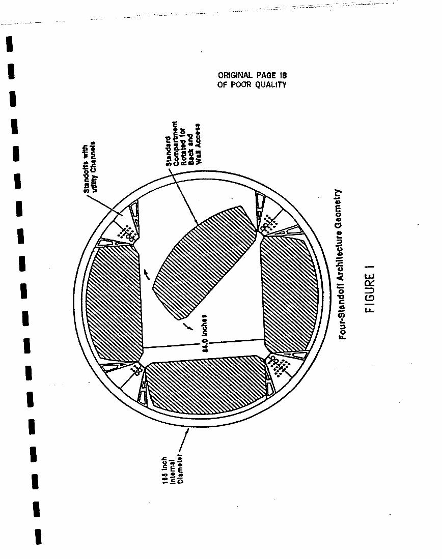
I I I I I I I I I I I I I I I I I I 1
OMGiNAL PAGE IS OF POOR QUALITV
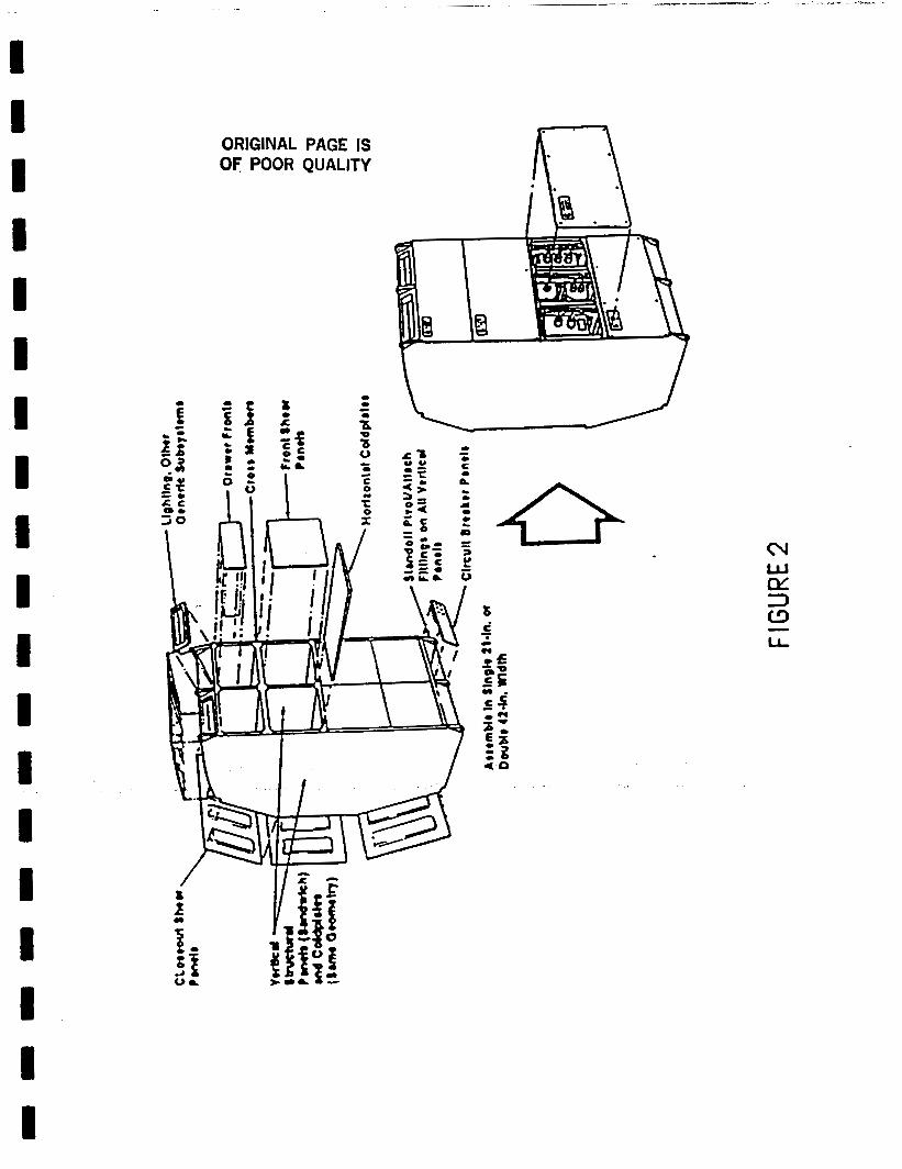
1 I I I I I I I I I I I I I I I I I I
ORIGINAL PAGE IS OF POOR QUALITY
N w CY 3 W LL -
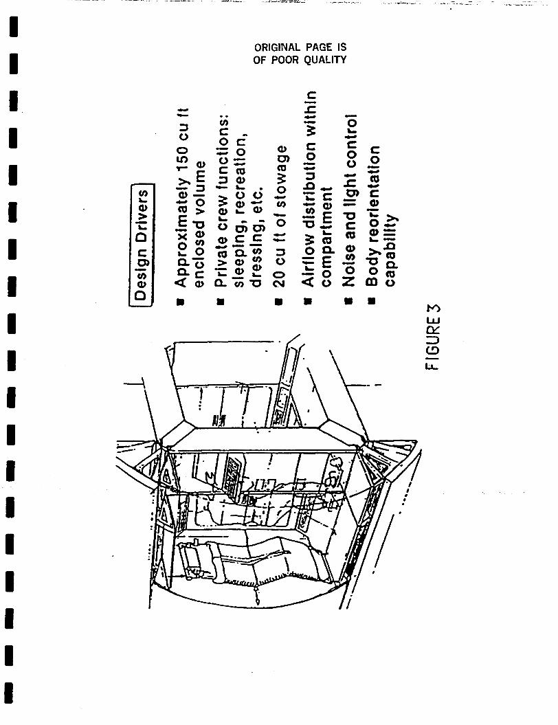
ORIGINAL PAGE IS
n
U
c. - 3 0 0
OF
.. tn t
L O - 0 6
POOR QUALITY
a 0) rn 0 v)
3 L
)-.
0
3 0 0 cv
Y .c
- /
0
m m
1 I
I I
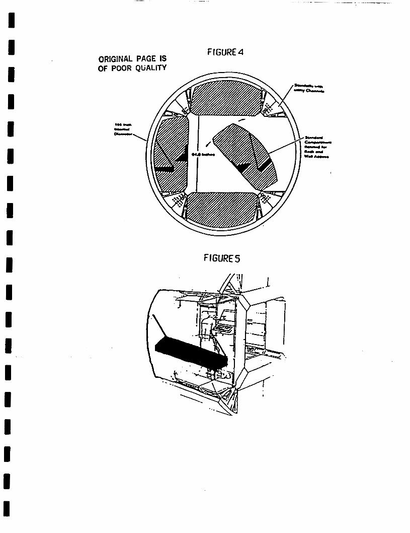
I I
ORIGlNAL PAGE IS Of POOR QbALITY
FIGURE4
I I I
FIGURE5
I I I
1 . . .
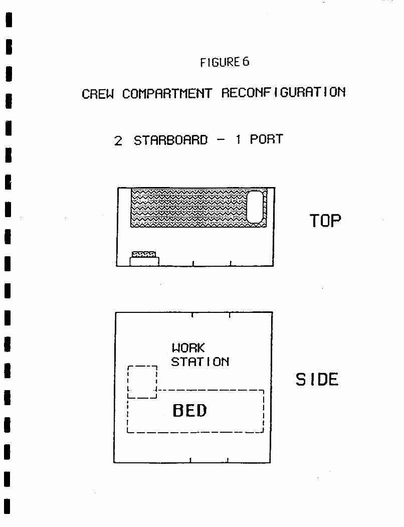
F 1 GURE 6
I I
CREW COflPflRTMENT RECONFIGURRTION
2 STFtRBOflRD - 1 PORT
TOP
I
I I
WORK STAT I ON r-- 1
I I I I
BED
1 1
SIDE
I I
I I I I I 1 I I I I 1 I I I I I I I I
Chapter 13
COMPUTER MODELING AND SIMULATION OF TETHER VIBRATIONS
13.1 Definition of Topic
This chapter describes computer software that simulates the vibrations created in the Variable Gravity Research Facility (VGRF) tethers by impulse forces applied to the External Tank-Habitation Module (ET-HM) system. A user friendly interface allows the modeling of various system configurations.
13.2 Background Information and Assumptions
Much of the information and the mathematical equations used in this simulation has been obtained from the University of North Dakota mechanical engineering team which is working on a physical simulation-model.
13.3 Proposed Mission Requirements
The proposed requirements, the dynamic simulation of tether vibrations and resulting data, can be used to predict the dynamic characteristics of a full-sized ET-HM system in space and aid the engineering team in establishing the accuracy of their physical model.
13.4 Proposed Method of Meeting Mission Requirements
The requirements are met by creating software for the IBM personal computer. The language used in programming the simulation is Turbo Pascal version 4.0, which offers a unique combination of speed, simplicity and graphics routines.
The actual software consists of three major components. first is an interface that allows the user to modify specific parameters of the dynamic simulation. The second, and most critical portion of the software, is an analytical section that quickly and efficiently solves the pertinent mathematical equations and provides information to the graphics routine at a reasonable rate and with adequate resolution. graphics routine that uses the specified parameters and the output of the analytical section to perform on-screen graphing and evaluation of the simulation.
The
The third is a
The mathematical equations that describe the oscillatory relationships between the masses in the ET-HM system are as follows:
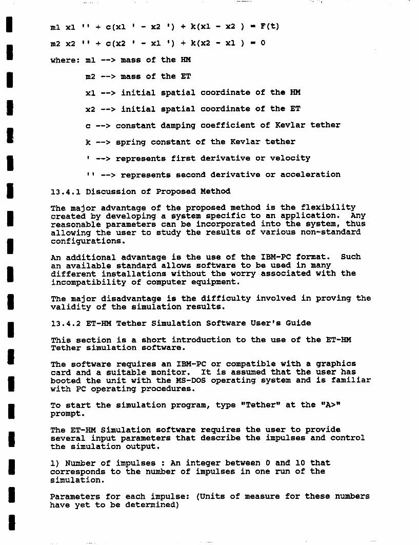
ml xl ' I + c(x1 I - ~2 I ) + k(x1 - x2 ) = F(t)
m2 x2 ' I + c(x2 - xl I ) + k(x2 - xl ) = 0
where: ml --> mass of the HM
m2 --> mass of the ET
xl --> initial spatial coordinate of the HM
x2 --> initial spatial coordinate of the ET
c --> constant damping coefficient of Kevlar tether
k --> spring constant of the Kevlar tether
I --> represents first derivative or velocity
I 1 --> represents second derivative or acceleration
13.4.1 Discussion of Proposed Method
The major advantage of the proposed method is the flexibility created by developing a system specific to an application. Any reasonable parameters can be incorporated into the system, thus allowing the user to study the results of various non-standard configurations.
An additional advantage is the use of the IBM-PC format. an available standard allows software to be used in many different installations without the worry associated with the incompatibility of computer equipment.
Such
The major disadvantage is the difficulty involved in proving the validity of the simulation results.
13.4.2 ET-HM Tether Simulation Software User's Guide
This section is a short introduction to the use of the ET-HM Tether simulation software.
The software requires an IBM-PC or compatible with a graphics card and a suitable monitor. It is assumed that the user has booted the unit with the MS-DOS operating system and is familiar with PC operating procedures.
To start the simulation program, type "TetherII at the "A>" prompt . The ET-HM Simulation software requires the user to provide several input parameters that describe the impulses and control the simulation output.
1) Number of impulses : An integer between 0 and 10 that corresponds to the number of impulses in one run of the simulation.
Parameters for each impulse: (Units of measure for these numbers have yet to be determined)

a) Impulse start time : An integer between 0 and 32000
b) Impulse amplitude factor: This number corresponds to the
(32000 is the maximum time displayed).
magnitude of the vibration. the wave may become ungraphable.
If this number becomes too large
c) Impulse frequency factor: This number directly relates to the wavelength of a specific impulse.
d) Number of repetitions: Number of times signal will be repeated.
e) Time between repetitions:
2) Length of simulation: This number is an integer between 1 and 32000 that allows you to determine the length of the simulation.
3) Scaling factor: Represents the range of the Y axis when graphing the function. the scaling factor.
The Y axis will range from +/- 10 times
Currently the time units are pixels across the screen. across one display is therefore 640 pixels (i.e., 640 arbitrary time units).
The time
13.5 Alternate Methods of Meeting Mission Requirements
Software packages are available for modeling some physical systems. Such packages would most likely require modification to fit these needs. development time required to write specialized software, but would require a considerable amount of learning time. Many of these packages are either not on computers with easy access or are not transportable.
13.6 Discussion of Unresolved Issues
Using packaged software would reduce the
It is not clear at this time just how closely the model will simulate either the ET-HM physical model or an actual tethered ET-HM system in space. The mathematical equations that describe the system require more study and have yet to yield a reasonable solution.
13.7 Summary
The vibrations in the ET-HM tethered system is very difficult to model and simulate because of the extremely complex and non-linear equations that are involved. these equations is not feasible and many assumptions will have to be made to reduce the mathematical problem to a level where solution is possible (13001).
A complete solution of
13.8 References
13001 Anderson, W.W. No date. On lateral cable oscillations of cable- connected space stations. TN 5107. Pages unnumbered. Langley Research Center: NASA .
NASA
1 I I 1 t # 1 I I
13002 Carroll, J.A. 1985. Guidebook for analysis of tether applications. Contract RH4-394049. 45p. Marshall Space Flight Center, AL: George C. Marshall Space Flight Center.
reference manual NASA Contract NAS9-16715. unnumbered. Washington, DC: NASA.
13003 Lang, D.D. 1983. Tethered object simulation system Pages
13004 Anonymous. 1983. Turbo pascal reference manual. 1983. 254p. Scotts Valley, CA: Borland Internat. Inc.
Chapter 14
COST ESTIMATE
I I I I 1 1
8 1 I I I 3 I E C I 8 I
14.1 Definition of Topic
This chapter makes a preliminary estimate of costs of manufacturing the Variable Gravity Research Facility (VGRF), orbiting it, and orbiting personnel and supplies for the three
14.2 Background Information
It is assumed that the habitation module well as the node and Crew Emergency Return Vehicle (CERV) will all be obtained from the International Space Station (SS) program and that that program will cover the cost of design and manufacturing. modifications to these components both for VGRF specific requirements and for return to SS configurations before they are incorporated into the SS.
(HM) of the VGRF as
The VGRF program will only cover the cost of
It is further assumed that the cost of launching components which will be used on the SS will be funded by the SS program, so that the VGRF program will only need to pick up launch costs which are VGRF specific.
14.3 Proposed Mission Requirements
The mission requirements include keeping costs to a minimum so that the VGRF program can be politically feasible in a Congressionally controlled tight budget situation.
14.4 Proposed Method of Meeting Mission Requirements
The VGRF program has been conceptualized in such a manner that the costs will be minimal. The primary mechanism for this has been to utilize equipment already developed for the SS. Modifications of this equipment have been kept to a minimum to reduce initial configuration and reconfiguration costs.
14.4 1 Equipment Costs
Following is a list of modifications to the HM and node:
Beds must be horizontal to the artificial gravity direction rather than at various angles.
Equipment support racks will be required on orbit.
Fuel cell units will
The radiator will be HM.
The antennae will be HM.
be housed in the
mounted directly
mounted directly
HM.
to the outside of the
to the outside of the
The node, derived from SS node-2, will have one connecting adaptor changed from a module connector to a shuttle docking connector.
These changes are all quite small. bending, which is normally cheap, rack replacement, or reducing the length of connectors to outside equipment.
The estimated cost for the above changes is under 10 million dollars.
They are either metal
The CERV will be unmodified.
Equipment unique to the VGRF program includes:
The tethers and their connectors and separators will have to be designed and manufactured specifically for this program.
The rocket motors for spin up are not used in the SS program but are available from other sources.
ET fuel recovery equipment is under development and will be avavilable.
These items should cost under 100 million dollars to fabricate and, where neccessary, design.
14.4.2 Launch Costs
All together five shuttle flights will be involved. encompass the following activity.
They will
1st
2nd
3'rd
Shuttle Flight for VGRF will:
launch the HM and insert it in stable LEO.
Shuttle Flight for VGRF will:
orbit the node, CERV, ET, tether, and first crew; rendezvous with the HM; assemble the VGRF; install the first crew.
Then the VGRF will spin up for the first mission.
Shuttle Flight for VGRF will:
orbit another ET, tether, and the second crew; recover the first crew and experimental samples: attach tethers and ET to the HMt load consumable supplies into the HM.
Then the VGRF will spin up for the second mission.
The Shuttle will have additional pay load space available on this mission for other activities as well.
4th Shuttle Flight for VGRF will:
orbit another ET, tether, and the third crew; recover the second crew and experimental samples; attach tethers and ET to the HM; load consumable supplies into the HM.
Then the VGRF will spin up for the third mission.
The Shuttle will have additional pay load space available on this mission for other activities as well.
5rd Shuttle Flight for VGRF will:
recover the third crew and experimental samples; move the HM, node, and CERV to the SS for installation.
Shuttle costs than can be shared between the VGRF, SS, and other programs. Costs are allocated below:
Flight VGRF ss other
Total 2 2 1
Shuttle costs at 110 million dollars each will cost the VGRF program 220 million dollars.
Therefore, the total on orbit costs will be:
Internal modifications to the HM, node, CERV
VGRF mission specific equipment
Equipment subtotal
$ 10 million
$100 million
$110 million
Two shuttle flights $220 million
TOTAL ON ORBIT COSTS less than $400 million
The funding sequence of the fabrication of the HM, node, and CERV will need to be speeded up so that these can be placed on orbit two years earlier than planned for the SS. increasing the cost, it does change the distribution of these costs during various fiscal years. trivial problem.
While not
This in itself is not a
14.5 Alternate Methods of Meeting Mission Plan
14.5.1 A Dedicated VGRF
A dedicated VGRF could be built if the HM, node, and CERV were not placed into the SS. these parts would have to be manufactured. the second unit of such systems is much cheaper than the first because the design costs have already been covered. assumes that ordering of the second unit would be done in a first unit could used without interruption. We estimate that the second units of the three parts could be manufactured for 350 million dollars. three missions of the program to under 750 million, still a cheap program. Additional missions would of course increase launch costs as well.
This means that duplicate units of The marginal cost of
This
This increases the cost through the first
This alternative was rejected because we felt that preliminary information on human physiology could be obtained with the three missions planned and the need for this information was so great that it should be obtained as quickly as possible. A dedicated facility would undoubtedly be brought on line several years later than a temporary facility.
14.6 Discussion of Unresolved Issues
We still need to persuade NASA to adopt and Congress to fund the program.
14.7 Summary
The total manufacturing and launch costs for all three missions can be covered with a VGRF program of less than 400 million dollars.
Chapter 15
TEST EQUIPMENT AND MODEL OF VGRF TO STUDY STABILITY OF TETHERS
15.0 Abstract
This system was design to study the cable tether stability for the NASA Variable Gravity Research Facility (figure 15.1).
The design consists of a dimensionally scaled model of the VGRF, a spinup apparatus and 2 camcorders. information pertaining to the dimensions of the habitation module. The actual HM has a mass of 15,531 kg, a length of 13.8 m and a diameter of 4.4 m. information pertaining to the dimensions of the external tank. The actual ET has a mass of 31,317 kg, a length of 46.3 m and a diameter of 8.5 m. Dimensional similitude was used to model the VGRF. The scale for the dimensions of the ETM and the HMM is 1:75, for the tether length is 1:125, and for the tether diameter is 1:50. No scale was used to determine the mass of the ETM and the KMM, rather, the ratio of 1:2 was maintained between the two.
McDonnel Douglas provided
Martin Marrietta provided
Disturbances in the HMM, simulating human movement, were introduced in the HMM using a small electric motor and an offset cam.
The VGRF model was spun-up with the test equipment and released using an electromagnetic triggering device. mounted on the test apparatus, recorded the VGRF model during its free flight from the ceiling to the floor. provided zero g for 1.1 seconds.
The camcorders,
This procedure
Tests have shown that the design is able to detect the disturbances placed on the system. measurements of these disturbances an alternate method of data acquisition should be explored.
To obtain actual
15.1 Introduction
The objective of this project was to design test equipment to study the cable tether stability of the VGRF.
The stability of a tether system is described by its response to disturbances applied to the system. Interstel is concerned with disturbances that originate within the habitation module, due to some movement within the module. These disturbances are caused by offsetting the center of gravity of the VGRF or impulses applied on the habitation module walls.
A stable tether system for the VGRF is needed for two reasons, the first of which is so it will maintain its original orientation in orbit. the habitants of the HM. Specification of vibration tolerance levels on humans are provided by the secretariate of the IS0 and include: - Frequency of vibration of 2.5 to 10 Hz.
The second reason wonders the comfort of
- Amplitude
of vibration less than 6db - Maximum acceleration of 0.30 meters per second"2 Different tether configurations between the habitation module and the external tank affects the modes of vibration of the VGRF. These modes of vibration include the amplitude of vibration, resonant frequency, and damping ratio due to the disturbances and the physical parameters of the VGRF.
The equipment is designed to study the scaled model of the VGRF. Disturbances were scaled to simulate the vibrations that could occur in the actual habitation module. designed such that different tether configurations and disturbances could be applied. The disturbance responses of the VGRF have been recorded by two camcorders mounted on the test spin-up device. Replay of the data recorded, allows the affects of the disturbances to be studied. The parameters measured include the frequency of vibration, amplitude and maximum acceleration.
The model VGRF was
15.2 Background
This project was the result of a grant from the National Aeronautics Space Administration (NASA) through the Center for Aerospace Sciences (CAS) at the University of North Dakota.
One of NASA's short term goals (within 15 years) is to determine the physiological aspects of long-term space habitation.
It is believed that certain functions of the human body decays exponentially with time in gravity below that here on earth. The concern is whether or not humans can take long term journeys in space and return to earth without any or little long term physical effects.
One proposal is to develop a Variable Gravity Research Facility that is composed of a habitation module, designed by McDonnell Douglas, which has a mass of 15,531 kilograms and an external tank of 31,317 kilograms. This system will rotate about the center of mass at 3 revolutions per minute, inducing a simulated gravity of -255, .34 or .64g. Kevlar 29 is used as the tether material and will be Teflon coated to minimize the degradation due to exposure to the sun. resulting in a safety factor of 10 and will have a length of 200 meters.
15.3 Technical Information
See figure 15.2 and 15.3 for detail drawing of spin up device.
Its diameter will be 2.5 cm
A) VGRF Model #lo
1. Habitation Module Model. (HMM)
The HMM consists of 3 parts, the hull and 2 end caps. The hull is constructed of Polyvinylchloride (WC) pipe 14.5 cm long and 5.9 cm in diameter. The end caps are produced according to design specifications from 5.9 crn diameter pine wood cylinders which are hollowed out to reduce weight.

The HMM is 18.5 cm in length with a diameter 5.9 cm and a mass of .38 kg. using a scale of 1:75.
These sizes have been determined
2 . External Tank Model. (ETM)
The ETM is constructed using a scale of 1:75. It was composed of a nose cone, a hull and an end cap. The nose cone and the end cap were shaped from an 11.43 cm diameter Styrofoam cylinder. The hull is constructed of W C pipe, 11.2 cm in diameter and 42 cm in length.
The ETM's overall dimensions are length 61 cm in length and 11.2 cm in diameter. The mass of the ETM .77 kg.
B) VGRF Model #2.
1. Habitation Module Model. (HMM)
This second model is fabricated from 100% balsa wood and is coated with a polyurethane and paint. The overall dimensions of this HMM were the same as Model #1 using the same scaling factor.
2. External Tank Model. (ETM)
The second ETM is also fabricated from balsa wood and coated with the polyurethane. The ETM has an overall dimension and scales equal to those of the previous ETM model.
C) Tethers.
The scaled tether material used to link the HMM and the ETM is 9.78 kN test compound bow hunting line. A second tether material that is used is Kevlar 29.
D) Fasteners.
A screw assembly with tapped sheath is being used to attach the tether to the HMM and the ETM. This design allows simple reconfiguration of the tether system.
E ) Drive System.
A 1/2 Hp DC motor is being used to induce the rotation of the Model System. A potentiometer and a double reduction pulley system are incorporated to control the speed of the system.
Speeds from 50 to 100 rpm are being utilized to simulate different g levels to test the scaled VGRF system. A 2.2 cm diameter shaft supported by Timken Taper Bearings, are to support the VGRF Model and Camera System. .
The two tapered bearing mounts are fabricated two 15x9x1.1 cm aluminum plates. These plates are fastened together and mounted to the system cage using 1.27 cm hex-head bolts. Each pair of upper and lower plates incorporates a 5 cm and 3.8cm holes respectively. These holes provide a mount for the taper bearing described above.
from
The collar used on the shaft to keep in place on the taper bearing was a 2.8 cm OD, 2.2 cm ID tube with a set-bolt through the collar and shaft. The length of the collar is 3 cm.
An rpm indicator is attached to the shaft on the GE motor.
A cage has been fabricated to rigidly house the drive system. The cage was manufactured using 3 cm angle-iron and its overall dimensions are as follows, 30.4 x 34.7 x 71.7 cm.
F) Camera Arm
The camera arm supports the two Hitachi camcorders and the VGFW model. It is fabricated from 3cm channel- iron. The length of the arm is 243.5 cm. A 90 cm system of slots has been machined on both sides of this arm to allow positioning of the cameras and the movable counter weight.
The its center by the stationary support brace. This brace is comprised of a 13.38 cm length of 2.56 cm square tubing, whose center is welded in place at this position.
camera arm is supported 15 cm on each side of
At each end of the camera arm a movable support brace is located. A 1.27 cm hex nut has been welded in the end to allow repositioning wherever support is needed . Two 18.67 x 13.92 x 0.063 cm plates have been welded one above and one below on the center of the arm. A 2.96 dia. hole has been bored in the center of these plates to allow the insertion of the collar for the drive shaft.
G) Camera Mount
The camera mount has been designed to support the force exerted by the camera during system rotation.
The mount consists of 3 basic parts, the frame, the angle support and the support Shafts.
The frame has been constructed using 2, 33.4 cm lengths two sides, 3, in place between them creating a frame shape.
of 1.7 cm angle iron. Using the angle iron as 3.1 cm x 10 cm metal plates were welded.
- -
The angle support was fabricated using a 2.22 cm steel strip. A 17 cm and a 14.7 cm strip were welded together at a 35 degree angle.
The shafts here serve a dual purpose. First, they are tapped to allow insertion of a 1.27 cm hex bolts to hold the mount in the desired position. Second, they serve as another set of movable support braces for the arm. They have been fabricated from 2.14 cm dia aluminum shaft, 12.8 cm in length. They have been tapped to 1.27 cm.
The camera mount also incorporates two safety features. Besides the mounting screw the camera is also held in place using a system of nylon/velcro strapping.
Padding has also been applied to prevent damage to the camcorders.
15.4 Materials and Design
A. Variable Gravity Prototype.
1. Habitation Module.
The Habitation Module manufactured Douglas will be used as livins and
by McDonnel working for the
astronauts throughout their sfay in space . Quarters for the astronauts throughout their stay in space. Its advantages over other alternatives are that all supplies needed for the 6 months possible stay are onboard thus no EVA (Extra Vehicular Activity) or premature docking is required.
The External Tank (ET) is used here strictly as a counterweight for the rotation of the space station itself. The only modification made on it will be the addition of a linkage for the tether system which will be discussed in the next section. The advantage of using the ET for this purpose is that it is already part of the Shuttles payload thus none of the precious cargo bay space is wasted, and since the ET is simply brought up with the Shuttle into orbit and used in the design of the VGR instead of being jettisoned back to earth as it usually is, time as well as money will be saved.
3. Xevlar Tethers.
One inch diameter Xevlar 29 tethers manufactured by Cortland Cable company will be use as the load bearing members that span the 200 meters between the Module and the ET. Xevlar 29 was chosen because of its very high strength to weight ratio (5 times that of steel).
I 1 I i I I I i I 8 I I I I I 1 I 8 1
4 . Spinup and Spindown of the VGRF.
Spinup must be achieved in such a way, that the tether system will not become overstressed or twisted. The spindown is needed to allow replacement crews and supplies to be transferred to the Module. It would be very difficult for the Shuttle to dock with the VGRF during its rotation.
Spinup
a)Rockets with onboard fuel
b)Extra fuel in ET pressurized and allowed to escape through a nozzle to initiate spinup
c)Attach tether system to ET first, deploy the module and extend tethers. Use Shuttle for spinup release the ET.
Spindown
a)Release of the ET
b)Onboard rockets and fuel
Added weight of rockets and fuel is not desired. Would be difficult to control
This may be too hazardous to be considered.
Inexpensive, reliable no added weight . Added weight of rockets and fuel is not desired.
For our purposes we will consider spinup with rockets and onboard fuel and spindown will be accomplished by releasing the ET.
APPENDIX D
SYSTEM SPECIFICATIONS
VGRF Model #1 Specifications:
One Habitation Module Model and one External Tank Model. HMM consists of 3 parts, 2 end caps and one hull . End caps, fabricated from 5.9 cm dia. pine- wood cylinders, hollowed out to reduce weight. End caps are carved to fit snugly inside the hull and are removable. The hull is constructed from Polyvinylchloride (PVC) pipe, 14.5 cm long and 5.9 cm in diameter. The overall dimensions of the HMM #1 are 18.5 cm length and 5.9 cm diameter. The scale of the HMM#l is 1:75. The mass of the HMM#l is equal to -38 kg. The ETM consists of 3 parts, 1 nose cone, 1 end cap and 1 hull. The end cap and the nose cone are fabricated from 11.2 cm diameter pine and hollowed out as before. The hull is made up of an 11.2 cm diameter piece of PVC pipe 42 cm long. The ETM's overall dimensions were length 61 cm from nose to end and 11.2 cm diameter. The mass of the ETM is equal to .77 kg.
VGRF Model #2 Specifications:
1) One HMM and one ETM are required. 2) The overall dimensions for each of these are
equal to those for Model #l. 3) Each is formed from Balsa-wood blocks
according to specifications. 4) Each must be sealed and hardened with 4 coats
of a polyurethane spray and then painted needed.
5) The mass of the HMM is .38 kg.
as
6) The mass of the ETM is -77 kg.
Tether Specifications:
1) 9.78 kN break strength coumpound bow hunting line is currently being used as the test tether material.
2) This line is woven nylon. 3) Kevlar 29 with a diameter of 0.5 mm as an
alternate material.
Fastener Specifications:
I I I I
I 1
I I
1)
2)
A screw assembly with tapped sheath is used to attatch the tether to the HMM and ETM. The sheath is then epoxyed to the models and an eyelet in the head of the screw allows tether attatchment.
Drive System Specfifications:
1) A 1/2 Hp DC motor drives the VGRF model system.
3)
A double reduction pulley system with a stepped pulley, ( the exact size of which still being considered ) is being used to allow variable rotational speed to the system. A potentiometer allows adjustment of the speed of the motor (the system) more precisely for testing procedures. Speeds This corresponds to 3 to 12 g's of force. A 2.2 cm dia. system. 2 Timken Taper Bearings, support the load on the shaft. Bearing mounts were fabricated for the taper bearings. They consist of 2 plates 15 x 9 x 1.1 cm thick, bolted together by- 1.27 cm diameter hex bolts. The upper plate has a 5 cm dia. hole bored in it and the lower a 3.8 cm dia hole. A collar is provided to keep the shaft positioned. The collar has dimensions of 2.8 cm OD and 2.2 cm ID. It will be 3 cm in length. An rpm indicator has been attached to the GE motor to determine exact rpm during testing. This indicator is still under consideration. A cage to house the drive system has overall dimensions of 30.4 x 34.7 x 71.7 cm and is constructed of 3 cm angle iron. The drive shaft of the system must mounted in the exact center of the cage. The cage must be mounted very rigidly to the ceiling of the test facility to reduce the amount of vibration that will occur during system rotation.
from 50 to 100 rpm are to be utilized.
shaft is to drive and support the
Camera Arm Specifications:
1) The camera arm is made up of 2 support 2 movable support braces, 2 stationary support braces, 2 support plates and a collar for the drive shaft. The support arms are 243.5 cm lengths of 3 cm channel iron.
arms,
2 )
3) A system of slots will be machined 90 cm from each end on both sides to allow movement of the camera.
4) The stationary support brace is simply a piece of square tubing 13.38 cm long and 2.56 cm square.
5) The movable support brace has the same dimensions as 4) but a 1.27 cm hex nut is welded in each end.
6) The support plates are 18.67 x 13.92 x .063 cm plates with 2.96 dia. holes bored in their centers.
7) The collar is 2.87 cm OD and 2.2 cm ID. 8) The length of this collar is undetermined at
this point.
Camera Mount Specifications:
4)
The camera mount has been designed to support the camera during rotation at 212 rpm with a factor of safety of 3. The mount consists of 3 parts, the frame, the angle support and the support shafts. The frame is constructed from 2 33.4 cm lengths of 1.7 cm angle iron. 3, 3.1 cm x 10 cm plates are welded between these as described by the detail drawing. The angle support is fabricated using a cm steel strip. A 17 cm and a 14.7 cm strip are welded together at a Degree angle. 2, 1.27 dia holes are drilled in the 17 cm strip according to design criteria. The 2.14 cm dia. aluminum support shafts serve a dual purpose. First they allow a place to fix the mount to the camera arm, next, they act as another set of movable support braces for the arm. The have a length of 12.8 cm and have been tapped to 1.27 cm. The camera mount incorporates two safety features. Nylon and Velcro strapping has been utilized to assure proper camera support and positioning during system rotation. Padding has been applied to prevent damage to camcorders.
2.22
Camcorder Specifications:
1) At least 2 Hitachi camcorders required for proper testing of the VGRF Model.
Release Mechanism Specifications:
1) Two electromagnets will allow remote release of HMM and ETM during system rotation.
2) The core is made out of 1.1 cm diameter HRS rod 6.0 cm.
3) 24 guage copper wire is used for winding.
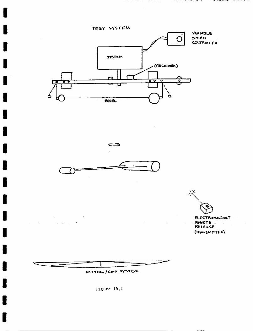
I I I
I I 1
Figure 15.1
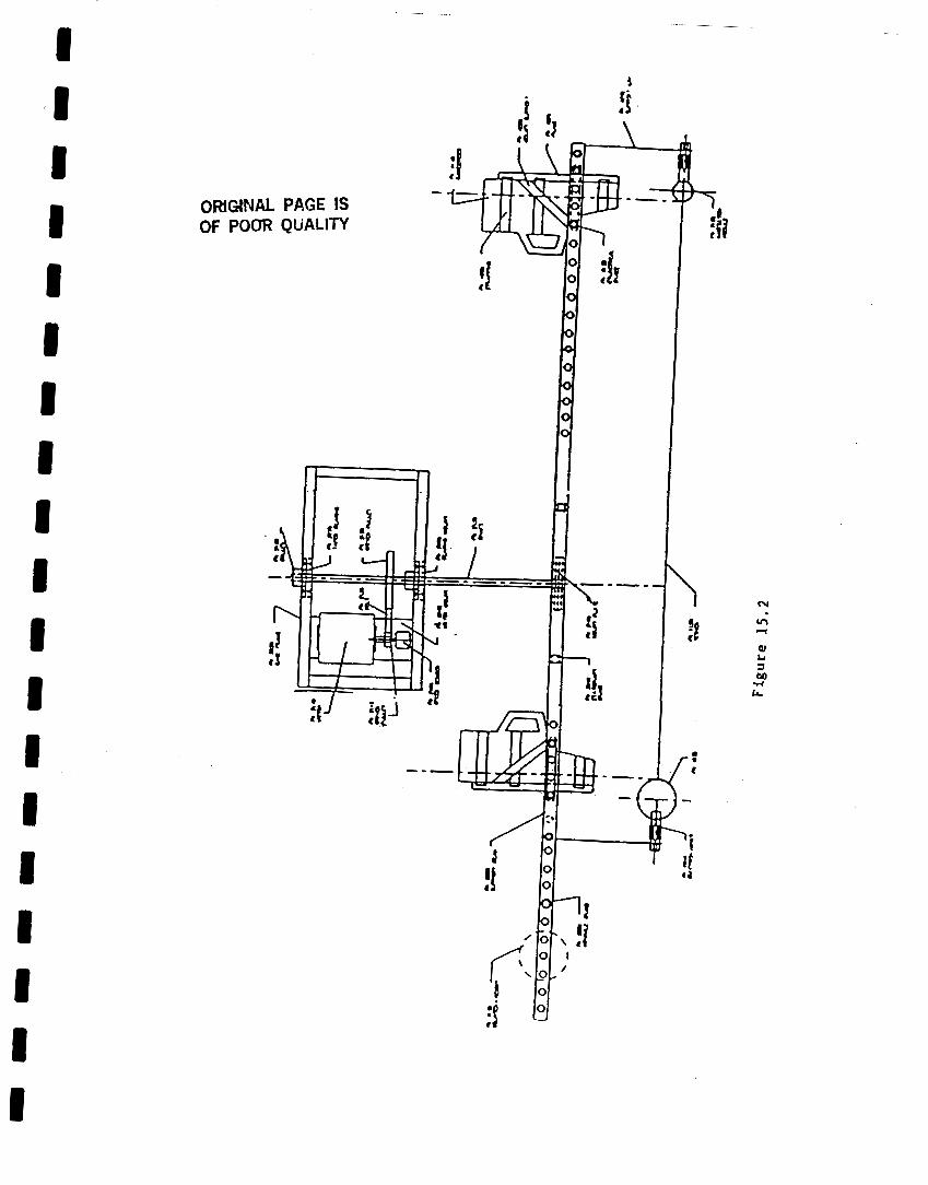
1 I I I I I I I I I I I I I I I I I I
ORIGNAL PAGE IS OF POOR QUALITY

ORIGINAL PAGE IS OF POOR QUALITY
Wloao - wni
Figure 1 5 . 3