Vapor Recovery Units - Oxygen Application Note
4
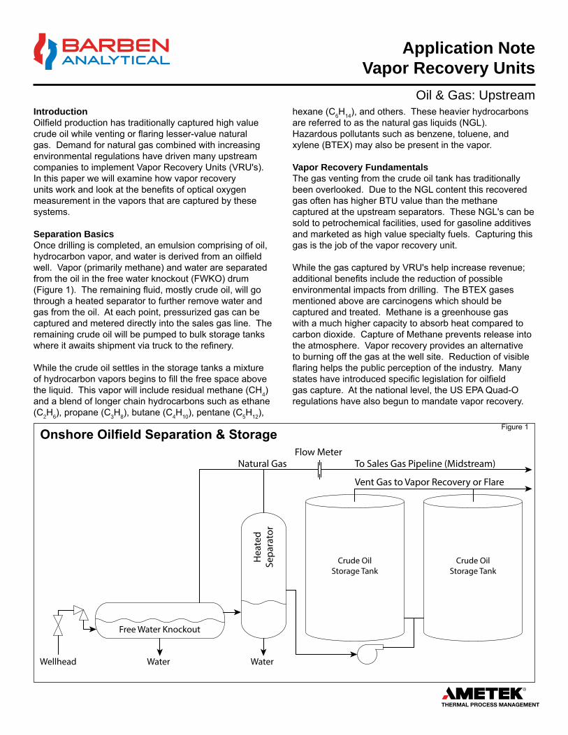
Application Note Vapor Recovery Units Oil & Gas: Upstream Introduction Oilfield production has traditionally captured high value crude oil while venting or flaring lesser-value natural gas. Demand for natural gas combined with increasing environmental regulations have driven many upstream companies to implement Vapor Recovery Units (VRU's). In this paper we will examine how vapor recovery units work and look at the benefits of optical oxygen measurement in the vapors that are captured by these systems. Separation Basics Once drilling is completed, an emulsion comprising of oil, hydrocarbon vapor, and water is derived from an oilfield well. Vapor (primarily methane) and water are separated from the oil in the free water knockout (FWKO) drum (Figure 1). The remaining fluid, mostly crude oil, will go through a heated separator to further remove water and gas from the oil. At each point, pressurized gas can be captured and metered directly into the sales gas line. The remaining crude oil will be pumped to bulk storage tanks where it awaits shipment via truck to the refinery. While the crude oil settles in the storage tanks a mixture of hydrocarbon vapors begins to fill the free space above the liquid. This vapor will include residual methane (CH 4 ) and a blend of longer chain hydrocarbons such as ethane (C 2 H 6 ), propane (C 3 H 8 ), butane (C 4 H 10 ), pentane (C 5 H 12 ), Onshore Oilfield Separation & Storage hexane (C 6 H 14 ), and others. These heavier hydrocarbons are referred to as the natural gas liquids (NGL). Hazardous pollutants such as benzene, toluene, and xylene (BTEX) may also be present in the vapor. Vapor Recovery Fundamentals The gas venting from the crude oil tank has traditionally been overlooked. Due to the NGL content this recovered gas often has higher BTU value than the methane captured at the upstream separators. These NGL's can be sold to petrochemical facilities, used for gasoline additives and marketed as high value specialty fuels. Capturing this gas is the job of the vapor recovery unit. While the gas captured by VRU's help increase revenue; additional benefits include the reduction of possible environmental impacts from drilling. The BTEX gases mentioned above are carcinogens which should be captured and treated. Methane is a greenhouse gas with a much higher capacity to absorb heat compared to carbon dioxide. Capture of Methane prevents release into the atmosphere. Vapor recovery provides an alternative to burning off the gas at the well site. Reduction of visible flaring helps the public perception of the industry. Many states have introduced specific legislation for oilfield gas capture. At the national level, the US EPA Quad-O regulations have also begun to mandate vapor recovery. Figure 1 Free Water Knockout Wellhead Water Heated Separator Water Crude Oil Storage Tank Crude Oil Storage Tank Natural Gas Flow Meter To Sales Gas Pipeline (Midstream) Vent Gas to Vapor Recovery or Flare
Transcript of Vapor Recovery Units - Oxygen Application Note
Application Note Vapor Recovery Units
Oil & Gas: UpstreamIntroductionOilfield production has traditionally captured high value crude oil while venting or flaring lesser-value natural gas. Demand for natural gas combined with increasing environmental regulations have driven many upstream companies to implement Vapor Recovery Units (VRU's). In this paper we will examine how vapor recovery units work and look at the benefits of optical oxygen measurement in the vapors that are captured by these systems.
Separation BasicsOnce drilling is completed, an emulsion comprising of oil, hydrocarbon vapor, and water is derived from an oilfield well. Vapor (primarily methane) and water are separated from the oil in the free water knockout (FWKO) drum (Figure 1). The remaining fluid, mostly crude oil, will go through a heated separator to further remove water and gas from the oil. At each point, pressurized gas can be captured and metered directly into the sales gas line. The remaining crude oil will be pumped to bulk storage tanks where it awaits shipment via truck to the refinery.
While the crude oil settles in the storage tanks a mixture of hydrocarbon vapors begins to fill the free space above the liquid. This vapor will include residual methane (CH4) and a blend of longer chain hydrocarbons such as ethane (C2H6), propane (C3H8), butane (C4H10), pentane (C5H12),
Onshore Oilfield Separation & Storage
hexane (C6H14), and others. These heavier hydrocarbons are referred to as the natural gas liquids (NGL). Hazardous pollutants such as benzene, toluene, and xylene (BTEX) may also be present in the vapor.
Vapor Recovery FundamentalsThe gas venting from the crude oil tank has traditionally been overlooked. Due to the NGL content this recovered gas often has higher BTU value than the methane captured at the upstream separators. These NGL's can be sold to petrochemical facilities, used for gasoline additives and marketed as high value specialty fuels. Capturing this gas is the job of the vapor recovery unit.
While the gas captured by VRU's help increase revenue; additional benefits include the reduction of possible environmental impacts from drilling. The BTEX gases mentioned above are carcinogens which should be captured and treated. Methane is a greenhouse gas with a much higher capacity to absorb heat compared to carbon dioxide. Capture of Methane prevents release into the atmosphere. Vapor recovery provides an alternative to burning off the gas at the well site. Reduction of visible flaring helps the public perception of the industry. Many states have introduced specific legislation for oilfield gas capture. At the national level, the US EPA Quad-O regulations have also begun to mandate vapor recovery.
Figure 1
Free Water Knockout
Wellhead Water
Hea
ted
Sepa
rato
r
Water
Crude OilStorage Tank
Crude OilStorage Tank
Natural Gas Flow Meter
To Sales Gas Pipeline (Midstream)
Vent Gas to Vapor Recovery or Flare

Crude OilStorage Tank
Crude OilStorage Tank
Vent Gas to Vapor Recovery or Flare
Scru
bber
Condensate Return to Storage Tank
Compressoror Eductor
Flow Meter
Sale
s G
as H
eade
r
BypassValve
Barben OxygenAnalyzer (VRU
Monitoring)
Flare Bypass
Suct
ion
line
Barben OxygenAnalyzer (Midstream
Monitoring)
Gas FromOther VRU sites
To GasProcessing
Plant
ESC
Oxygen 01/06/2017 10:55 AM
850.9 mBar67.9°FErr: 020.946
% O2
ESC
Oxygen 01/06/2017 10:55 AM
850.9 mBar67.9°FErr: 020.946
% O2
Application NoteVapor Recovery Units
2
How it worksGas vapor is drawn off the crude tanks through the suction line manifold (Figure 2). The manifold supplies the gas to a scrubber. The scrubber captures any residual liquid entrained in the gas. Condensed liquid is pumped off the bottom of the scrubber back into the crude tank. Gas vapor is routed from the top of the scrubber to the compressor. The compressor boosts the pressure of the gas to allow flow to the sales gas pipeline. At this point, the gas flow is measured so it can be documented for sales purposes.
Compressor control is critical in VRU design. Storage tank pressure is used to turn on/off the compressor. To avoid damage to the tank pressures as low as 5-10" of water must be accurately detected to start the compressor. Vacuum conditions must be avoided as outside air can be drawn into the tank and, in extreme cases the tank can be collapsed by excess vacuum. Pressure fluctuations may occur when the tank is emptied of crude oil or the thief hatch on top of the tank is opened to observe tank level or take a sample of crude oil.
The Dangers of OxygenIn all cases described above, air can enter the system. Air contains oxygen which is detrimental to the gas being captured by the VRU. There are many reasons to monitor for oxygen in the gas stream.
Corrosion - Oxygen combined with H2S and CO2 can form acidic condensation which harms piping.Purification - Oxygen is detrimental to the amine sweetening process at the gas processing plant.
Figure 2
Explosive limits - Too much oxygen can allow the gas to become flammable.Value - Air / oxygen in the gas stream reduces BTU content of the gas.
Midstream gas processing companies will have their own specifications for oxygen content in natural gas which is normally specified as part of their contract with the upstream producers. <10 Parts-Per-Million (PPM) is a common specification to meet interstate pipeline tariff requirements. When oxygen levels exceed 10 PPM then the gas will be blended with higher quality streams or possibly even rejected due to high oxygen content. When the gas is rejected due to high oxygen content it will be flared off to prevent contamination of gas from other wellheads. The end result for the upstream producers are lost revenues and even potential environmental fines.
Oxygen Monitoring TechniquesOxygen measurement at the vapor recovery unit has been problematic for many sensing technologies. Both paramagnetic and tunable diode laser (TDLAS) oxygen analyzers are relatively new technologies. These products work well in % oxygen measurements but lose their accuracy at the low part-per million levels required for these applications. Electrochemical oxygen sensors (sometimes referred to as a "Clark Cell") have typically been used for these applications because of their ability to measure at low O2 levels. Unfortunately these sensors have their own application issues.
Electrochemical oxygen sensors function similar to a battery using a cathode and a lead (Pb) anode in an
Vapor Recovery Unit

Application Note Vapor Recovery Units
3
electrolyte solution. An oxygen permeable membrane allows oxygen molecules to enter the cell where theyreact with the electrolyte creating a voltage response to the changing oxygen level (Figure 3). H2S and trace amounts of BTEX gases can poison the electrochemical cell causing drift, frequent recalibration and eventual death of the cell. Often a sample line scrubber is installed upstream from the electrochemical cell to remove the contaminant gases. The scrubber adds to the maintenance and complexity of the sample system. Condensed moisture can also create measurement error by plugging the permeable membrane of the electrochemical cell. Coalescing filters to block water and hydrocarbons must be used (and maintained) to ensure good performance. Over time, whether due to poisoning or age, the output of the cell begins to drop. As this occurs, the measurement will trend towards 0% oxygen. Such low readings gives the end-user a false sense of security that their vapor recovery unit has no outside air contamination in the gas vapors. In reality high levels of oxygen could be entering the pipeline and creating havoc with the downstream equipment.
Optical Oxygen Measurement - A New ApproachFluorscent quenching technology is relatively new approach to gas phase oxygen measurement. This sensing technique relies on an oxygen sensitive luminophore dye coating exposed to the process gas. When the luminophore is excited by a blue light source it luminesces or "glows" back with a red light (Figure 4). The presence of oxygen at the luminophore has a quenching effect of reducing the intensity of this luminescent light as well as shifting the wavelength of the light. Both intensity and wavelength are used in conjunction with each other to accurately measure oxygen to part-per-million levels.
Advantages of optical oxygen measurement in vapor recovery applications include the following:
• Greatly reduced maintenance compared to competitive technology
• High measurement accuracy at low part-per-million oxygen levels• No poisoning by contaminant gases such as H2S• Ability to measure in the presence of condensed moisture• Optical sensor fails "high" thus preventing a false sense of
security in the measurement
+ -
Oxygen Permeable Membrane
Anode
Electrolyte
Cathode
Electrochemical Cell O2 Sensor
Figure 3
• Sensitive to flow and pressure changes• Membrane sensitive to fouling, coating and attack• Electrolyte poisoning
Figure 4
Pulsed light from the analyzer excites the luminophore oxygen sensor. Once excited, the luminophore emits light which is measured back at the analyzer. The duration and wavelength of the light will vary depending on the oxygen concentration in the liquid.
The OXYvisor Optical Oxygen Analyzer & BOS Sensor shown above.
Figure 5

Cert. No. 43271ISO 9001:2015
© 2020, by AMETEK, Inc. All rights reserved • BA-APP-VRU-20RC
TF: +1-800-993-9309 • P: +1-775-883-2500 • F: +1-775-883-6388E: [email protected] • W: BarbenAnalytical.com
Application NoteVapor Recovery Units
Barben Analytical reserves the right to make tevchnical changes or modify the contents of this document without prior notice. We reserve all rights in this document and in the subject matter and illustrations contained within.
Barben Analytical recommends using our OXYvisor Optical oxygen analyzer in VRU applications. This productcan be powered from conventional 120/240VAC or 24VDC (4 wire) for solar / battery powered applications. The BOS3 optical sensor with a range of 0 - 300 ppm is well suited for vapor recovery applications. The sensor can be supplied as a basic system that includes the OXYvisor Analyzer, BOS Optical Sensor and Flow Cell (Figure 5) or as a full sample conditioning panel which includes all of the ancillary tubing, valves, filters, and flow meters. The analyzer and related sensors ship pre-wired and mounted directly to the panel. The SCP panel can save considerable engineering and design work in new installations (Figure 6). The Insitu SafeTap Installation is shown in (Figure 7).
The SCP-OXY Sample Calibration Panel provides a convenient pre-engineered manual calibration solution for sample line installations.
Figure 6
Figure 7
Contact UsBarben Analytical is a leading supplier of analytical measurement technology targeting the industrialmarketplace. It is a wholly owned subsidiary of AMETEK, Inc., a leading global manufacturer of electronic instruments and electromechanical devices.
AMETEK has over 15,000 colleagues at more than 120 manufacturing locations around the world. Supporting those operations are more than 100 sales and service locations across the United States and in 30 other countries around the world.
Barben Analytical Toll Free: +1-800-993-9309Phone: +1-775-883-2500Fax: +1-775-883-6388Email: [email protected]: BarbenAnalytical.com
Model # SCP-OXY-M-P-X Rev A, 0119, Made 0119Manual Calibration Panel
www.BarbenAnalytical.comMade USA - Carson City NV
+1.775.230.6611
FM1
BV1
OUTLET DRAIN
Pipe Mount
BV2
BV3
Process Rotam
eter
Fastloop Rotam
eter
Pressure Gauge
CalibrationGas Inlet
Site Glass
Pressure Transmitter
CoalescingFilter
ParticulateFilter
O2 Sensor
Isolation orBack-PressureValve
BV6
SAMPLE
Flowcell RTD
Sample Probe - Extract Process Sample
Sample Calibration Panel w, O2, Pressure and Temperature sensors- Manual version Oxygen Analyzer
General Example - Extractive Measurement Installation
ESC
Oxygen 01/06/2017 10:55 AM
850.9 mBar67.9°FErr: 020.946
% O2 �
Gas Phase Applications: - Hydrocarbons - w/ H2S and CO2
- Nitrogen Headers - Annealing Furnaces - Hydrogen - Biogas - Upstream Natural Gas Applications
Safe-T- Handle
Pressure xmmtr
SafeTap - Insitu Probe w/ O2, Temperature and Pressure Sensors Oxygen Analyzer
General Example - Insitu Measurement Installation
Gas Phase Applications: - Hydrocarbons - w/ H2S and CO2
- Nitrogen Headers - Annealing Furnaces - w/ H2 - Biogas - Upstream Natural Gas Applications
Liquid Phase AppLICATIONS: - ENHANCED OIL RECOVERY (EOR) Waterflood and FloodWaters - Produced Water - Deaerators - Ethanol / Methanol - Dissolved Oxygen
Example - Insitu SafeTap - Installation
ESC
Oxygen 01/06/2017 10:55 AM
850.9 mBar67.9°FErr: 020.946
% O2 �
Hazardous Area Approvals IEC Ex, ATEX, NA - Zone 1 & Zone 2 IICcULus (NRTL) - Class I, Div 2, Groups A, B, C, D T4