
Valvola a farfalla a comando elettrico Electrically ... · NBR Nitrilelastomer PTFE...
18
Valvola a farfalla a comando elettrico Electrically actuated butterfly valve Vanne à papillon à commande électrique Absperrklappe mit elektrischem Antrieb FE/CE
Transcript of Valvola a farfalla a comando elettrico Electrically ... · NBR Nitrilelastomer PTFE...

Valvola a farfalla a comando elettricoElectrically actuated butterfly valveVanne à papillon à commande électriqueAbsperrklappe mit elektrischemAntrieb
FE/CE

FE / CE
152
I dati del presente prospetto sono forniti in buona fede. La FIP non si assume alcu-na responsabilità su quei dati non diret-tamente derivati da norme internazionali. La FIP si riserva di apportarvi qualsiasi modifica.
The data given in this leaflet are offered in good faith. No liability can be accepted concerning technical data that are not directly covered by recognized interna-tional standards. FIP reserves the right to carry out any modification to the products shown in this Ieaflet.
Les données contenues dans cette brochure sont fournies en bonne foi. FIP n’assume aucune responsabilité pour les données qui ne dérivent pas directement des normes internationales. FIP garde le droit d’apporter tous les changements aux produits présentés dans cette brochure.
Alle Daten dieser Druckschrift wurden nach bestem Wissen angegeben, jedoch besteht keine Verbindlichkeit, sofern sie nicht direkt internationalen Normen entnommen wurden. Die Änderung von Maßen oder Ausführungen bleibt FIP vorbehalten.
FE / CE
153
Vanne à papillon à commande électrique
Valvola a farfalla a comando elettrico
• Valvola di intercettazione e rego-lazione.
• Gamma dimensionale da DN 40 a DN 200 mm, serie DIN 3202 K2 e ISO 5752 Medium serie 25.
• Resistenza a pressioni di esercizio fino a 16 bar a 20° C.
• Materiale corpo e disco: PVC-U.• Sistema di foratura con fori ovali
che permette l’accoppiamento secondo numerosi standard inter-nazionali.
• Tenuta primaria intercambiabile con manicotto in elastomero EPDM, FPM, NBR.
• Possibilità di installazione anche come valvola di fine linea o di scarico di fondo o rapido da serbatoio.
• Attuatore elettrico realizzato su specifiche FIP:
- Comando manuale di serie con indicatore visivo di posizione.
- Due finecorsa elettrici di segnala-zione forniti di serie.
ACCESSORI • posizionatore 4-20 mA o 0-10 V• unità fail safe • elemento riscaldante anti condensa• feedback di posizione• versione IP67 o ATEX
Per maggiori informazioni visitare il sito: www.fipnet.it.
Electrically actuated butterfly valve
• Used for fast control and ON/ OFF operations.
• Size range: from DN 40 up to DN 200 mm, series DIN 3202 K2 and ISO 5752 Medium series 25.
• Working pressure 16 bar at 20°C.• One piece body, and disc material:
PVC-U.• Oval holes body to fit with flanges
in different standards.• Interchangeable primary liner in
elastomer EPDM, FPM, or NBR.• Possible mounting of valve as
end valve, or quick discharge from tanks.
• Electric actuator produced on FIP specifications:
- Manual override and optical posi-tion indicator standard supplied standard.
- 2 Limit switches standard sup-plied.
ACCESSORIES • positioner 4-20 mA or 0-10 V• fail safe unit • heating resistor• position feedback• IP67 or ATEX execution
For more information please visit our website: www.fipnet.it.
• Vanne d’arrêt et de régulation.• Gamme dimensionnelle de DN 40
à DN 200 mm, série DIN 3202 K2 et ISO 5752 Médium série 25.
• Pression de service jusqu’à 16 bar à 20°C.
• Matériau corps et papillon: PVC-U.• Système de perçage par trous
ovales permettant l’accouplement selon plusieurs standard s inter-nationaux.
• Manchette interchangeable en élastomère EPDM, FPM, NBR.
• Possibilité de montage en fin de ligne, ou sur réservoir.
• Actionneur électrique réalisé sur spécification technique de FIP:
- Commande manuelle de série avec indicateur d’ouverture et fer-meture.
- 2 Micro interrupteurs fin de course standard.
ACCESSOIRES • positionneur 4-20 mA ou 0-10 V• système de sécurité fail safe • résistance de réchauffage• feedback de recopie• exécution IP67 ou ATEX
Pour avoir d’autres informations,visiter le site: www.fipnet.it.
Absperrklappe mit elektrischem-Antrieb
• Geeignet für Drossel- und Absperrfunktionen.
• Abmessungen von DN 40 bis DN 200 mm, entsprechend DIN 3202 K2 und ISO 5752 Baulänge mit-tel, Serie 25.
• Höchstzulässiger Betriebsdruck 16 bar bei 20°C.
• Einteiliger Klappenkörper und Klappenscheibe aus PVC-U.
• Vier ovale Schraubenlöcher für den Einsatz mit Flanschen nach verschiedenen Normen.
• Der Klappenkörper ist nicht me-diumberührt. Die Auskleidung ist mit der Dichtung kombiniert und auswechselbar, Ausführung in EPDM, FPM oder NBR.
• Die Absperrklappe kann auch als Schnellentnahmearmatur, z.B. an Tanks eingesetzt werden.
• Elektro-Antrieb nach FIP Spezifikation:
- Handbetätigung und optische Stellungsanzeige serienmassig Verfügbar.
- 2 zusätzliche Endschalter.
ZUBEHöR• 4-20 mA oder 0-10V Stellungsregler• Sicherheitssystem• Heizwiderstand• Positionsfeedback• IP67 oder ATEX Version
Für weitere Details schauen Sie auf unsere Website: www.fipnet.it.
FE / CE
154
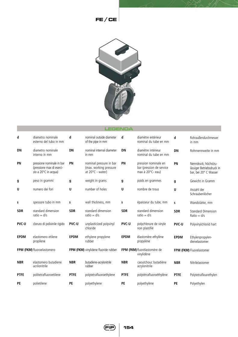
LEGENDA
d Rohraußendurchmesser in mm
DN Rohrnennweite in mm
PN Nenndruck; höchstzu-lässiger Betriebsdruck in bar, bei 20° C Wasser
g Gewicht in Gramm
U Anzahl der Schraubenlöcher
s Wandstärke, mm
SDR Standard Dimension Ratio = d/s
PVC-U Polyvinylchlorid hart
EPDM Ethylenpropylen- dienelastomer
FPM (FKM) Fluorelastomer
NBR Nitrilelastomer
PTFE Polytetraflourethylen
PE Polyethylen
d diametro nominale esterno del tubo in mm
DN diametro nominale interno in mm
PN pressione nominale in bar (pressione max di eserci-zio a 20°C in acqua)
g peso in grammi
U numero dei fori
s spessore tubo in mm
SDR standard dimension ratio = d/s
PVC-U cloruro di polivinile rigido
EPDM elastomero etilene propilene
FPM (FKM) fluoroelastomero
NBR elastomero butadiene acrilonitrile
PTFE politetrafluoroetilene
PE polietilene
d nominal outside diameter of the pipe in mm
DN nominal internal diameter in mm
PN nominal pressure in bar (max. working pressure at 20°C - water)
g weight in grams
U number of holes
s wall thickness, mm
SDR standard dimension ratio = d/s
PVC-U unplasticized polyvinyl chloride
EPDM ethylene propylene rubber
FPM (FKM) vinylidene fluoride rubber
NBR butadiene-acrylonitrile rubber
PTFE polytetrafluoroethylene
PE polyethylene
d diamètre extérieur nominal du tube en mm
DN diamètre intérieur nominal du tube en mm
PN pression nominale en bar (pression de service max à 20°C- eau)
g poids en grammes
U nombre de trous
s épaisseur du tube, mm
SDR standard dimension ratio = d/s
PVC-U polychlorure de vinyle non plastifié
EPDM élastomère ethylène propylène
FPM (FKM) fluorélastomère de vinylidène
NBR caoutchouc butadiène acrylonitrile
PTFE polytétrafluoroéthylène
PE polyethylène
FE / CE
155
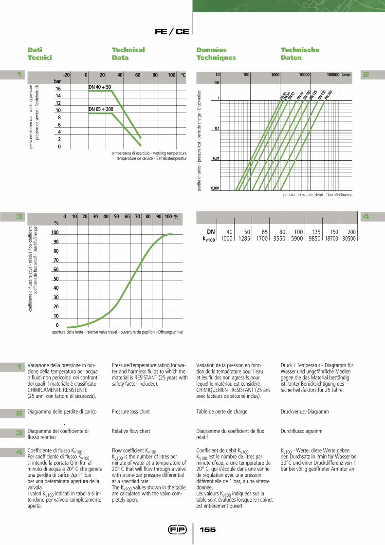
Variazione della pressione in fun-zione della temperatura per acqua o fluidi non pericolosi nei confronti dei quali il materiale è classificato CHIMICAMENTE RESISTENTE (25 anni con fattore di sicurezza).
Pressure/Temperature rating for wa-ter and harmless fluids to which the material is RESISTANT (25 years with safety factor included).
Variation de la pression en fonc-tion de la température pour l’eau et les fluides non agressifs pour lequel le matériau est considéré CHIMIQUEMENT RESISTANT (25 ans avec facteurs de sécurité inclus).
Druck / Temperatur - Diagramm für Wasser und ungefährliche Medien gegen die das Material beständig ist. Unter Berücksichtigung des Sicherheitsfaktors für 25 Jahre.
Diagramma delle perdite di carico
Coefficiente di flusso Kv100Per coefficiente di flusso Kv100si intende la portata Q in litri al minuto di acqua a 20° C che genera una perdita di carico ∆p=1 bar per una determinata apertura della valvola.I valori Kv100 indicati in tabella si in-tendono per valvola completamente aperta.
Pressure loss chart
Flow coefficient Kv100 Kv100 is the number of litres per minute of water at a temperature of 20° C that will flow through a valve with a one-bar pressure differential at a specified rate. The Kv100 values shown in the table are calculated with the valve com-pletely open.
Table de perte de charge
Coefficient de débit Kv100Kv100 est le nombre de litres par minute d’eau, à une température de 20° C, qui s’écoule dans une vanne de régulation avec une pression différentielle de 1 bar, à une vitesse donnée.Les valeurs Kv100 indiquées sur la table sont évaluées lorsque le robinet est entièrement ouvert.
Druckverlust-Diagramm
Kv100 - Werte, diese Werte geben den Durchsatz in l/min für Wasser bei 20°C und einer Druckdifferenz von 1 bar bei völlig geöffneter Armatur an.
Diagramma del coefficiente di flusso relativo
Relative flow chart Diagramme du coefficient de flux relatif
Durchflussdiagramm
Dati Tecnici
Technical Data
Données Techniques
Technische Daten
1
3
2
4
1
2
4
3
bar1614121086420
-20 0 20 40 °C60 10080
DN 40 ÷ 50
DN 65 ÷ 200
pres
sione
di e
serc
izio
- wor
king
pre
ssur
epr
essio
n de
ser
vice
- Bet
riebs
druc
k
temperatura di esercizio - working temperaturetempérature de service - Betriebstemperatur
DN 40
DN 50
DN 65
DN 80
DN 10
0DN
125
1000 l/min10000 10000010010
DN 15
0DN
200
bar
1
0,1
0,01
0,001perd
ita d
i car
ico -
pres
sure
lost
- pe
rte d
e ch
arge
- Dr
uckv
erlu
stportata - flow rate- débit - Durchflußmenge
%
100
90
80
70
60
50
40
30
20
10
0
0 10 20 30 %40 10050 60 70 80 90
apertura della lente - relative valve travel - ouverture du papillon - Offnungswinkel
coef
ficie
nte
di fl
usso
rela
tivo
- rel
ative
flow
coe
fficie
ntco
effic
ient
de
flux
rela
tif -
Durc
hflu
ßmen
ge DNkv100
651700
401000
501285
803550
1005900
1259850
20030500
15018700
FE / CE
156
FEOV/CE
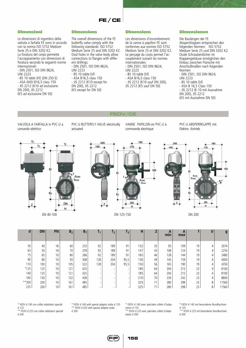
Dimensioni Dimensions Dimensions Dimensionen
Le dimensioni di ingombro della valvola a farfalla FE sono in accordo con la norma ISO 5752 Medium Serie 25 e DIN 3202 K2.La foratura del corpo permettel’accoppiamento con dimensioni di foratura secondo le seguenti norme internazionali:- DIN 2501, ISO DIN 9624,UNI 2223- BS 10 table D/E (DN 250 E)- ASA ANSI B16,5 class 150- JIS 2212 (K10 ad esclusioneDN 200), JIS 2212(K5 ad esclusione DN 50)
The overall dimensions of the FEbutterfly valve comply with thefollowing standards: ISO 5752Medium Serie 25 and DIN 3202 K2.Oval holes in the valve body allowconnections to flanges with differ-ent drillings:- DIN 2501, ISO DIN 9624,UNI 2223- BS 10 table D/E- ASA B16,5 class 150- JIS 2212 (K10 except for DN 200), JIS 2212(K5 except for DN 50)
Les dimensions d’encombrementde la vanne à papillon FE sontconformes aux normes ISO 5752Medium Serie 25 et DIN 3202 K2.Le perçage du corps permet l’ac-couplement suivant les normesinternationales:- DIN 2501, ISO DIN 9624,UNI 2223- BS 10 table D/E- ASA B16,5 class 150- JIS 2212 (K10 sauf DN 200), JIS 2212 (K5 sauf DN 50)
Die Baulängen der FE Absperrklappen entsprechen den folgenden Normen: ISO 5752 Medium Serie 25 und DIN 3202 K2.Ovale Schraubenlöcher imKlappengehäuse ermöglichen denEinbau zwischen Flansche mitAnschlußmaßen nach folgendenNormen:- DIN 2501, ISO DIN 9624, UNI 2223- BS 10 table D/E- ASA B 16,5 Class 150- JIS 2212 (K 10 mit AusnahmeDN 200), JIS 2212(K5 mit Ausnahme DN 50)
VALVOLA A FARFALLA in PVC-U a comando elettrico
PVC-U BUTTERFLY VALVE electrically actuated
VANNE PAPILLON en PVC-U à commande electrique
PVC-U ABSPERRKLAPPE mit Elektro- Antrieb
* FEOV d 140 con collari adattatori speciali d 125 ** FEOV d 225 con collari adattatori speciali d 200
* FEOV d 140 with special adaptor stubs d 125 ** FEOV d 225 with special adaptor stubs d 200
* FEOV d 140 avec spéciales collets d’adap-tation d 125 ** FEOV d 225 avec spéciales collets d’adap-tation d 200
* FEOV d 140 mit besonderen Bundbuchsen d 125 ** FEOV d 225 mit besonderen Bundbuchsen d 200
d
50637590
110*125
140160
**200225
DN
40506580
100125125150200200
PN
16161010101010101010
B2
60708093
105121121132161161
B7
253259266308322425425438485485
T1
929292
128128
-----
T2
189189189204204
-----
T3
919191
95,595,5
-----
H
132147165130150185185210325325
Z
33434649566464707171
Amin
93108128145165204204230280280
Amax
109124144159190215215242298298
f
19191919192323232323
g
20742254248040004350810081008800
1156011560
U
4444444488
DN 40-100 DN 125-150 DN 200
FE / CE
157
FE/CE LUG
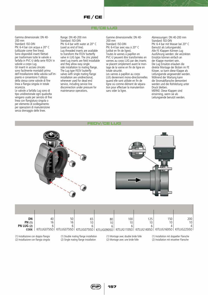
Gamma dimensionale: DN 40-200 mmStandard: ISO-DINPN: 6-4 bar con acqua a 20° C(utilizzate come fine linea).Sono disponibili inserti filettatiper trasformare tutte le valvole afarfalla in PVC-U della serie FEOV in valvole a corpo Lug.Gli inserti in acciaio zincatosono facilmente montabili primadell’installazione della valvola sull’im-pianto e consentono l’utilizzodella stessa come valvole di finelinea a flangia singola in totalesicurezza.Le valvole a farfalla Lug sono ditipo unidirezionale ogni qualvoltavengano usate per servizio di finelinea con flangiatura singola oper elemento di scollegamentoper operazioni di manutenzionesenza drenaggio delle linee.
Range: DN 40-200 mmStandard: ISO-DINPN: 6-4 bar with water at 20° C(used as end of line).Lug threaded inserts are availableto transform the FEOV butterflyvalve in LUG type. The zinc platedsteel Lug inserts are field installable and they allow easy singleside installation to mating flange.The Lug type FEOV butterflyvalves with single mating flangeinstallation are unidirectional,whenever used for dead endservice, including service linedisconnection under pressure formaintenance operations.
Gamme dimensionnelle: DN 40-200 mmStandard: ISO-DINPN: 6-4 bar avec eau à 20° C(utilisé en fin de ligne).Toutes le vannes à papillon enPVC-U peuvent être transformées en vannes au corps LUG par des inserts se placent simplement avant le mon-tage de la vanne en fin de ligne en totale sécurité.Les vannes à papillon au corpsLUG deviennent mono-directionnelles quand elle sont utilisée en fin de ligne où comme élément de sépara-tion pour effectuer la manutention sans vider la ligne.
Abmessungen: DN 40-200 mmStandard: ISO-DINPN: 6-4 bar mit Wasser bei 20° C(benutzt als Leitungsende).Alle FE Klappen Können LugAusführung werden: die verzinkten Einsätze können einfach ander Klappe montiert sein.Die Lug Einsätze erlauben diedirekte Montage der Bolzen im FEKörper, so kann diese Klappe alsLeitungsende angewendet werden.Während der Wartung kanndie Stromabflansche demontiertwerden und die Rohrleitung unterDruck bleiben.MERKE: Diese Klappen sindeinsinning, wenn sie alsLeitungsende benutzt werden.
FEOV/CE LUG
125106
KITLUG140ISO
DNPN (1)
PN LUG (2)CODE
65106
KITLUG075ISO
50166
KITLUG075ISO
40166
KITLUG075ISO
80106
KITLUG090ISO
100106
KITLUG110ISO
150104
KITLUG160ISO
200104
KITLUG225ISO
(1) Installazione con doppia flangia(2) Installazione con flangia singola
(1) Double mating flange installation(2) Single mating flange installation
(1) Montage avec double bride folle(2) Montage avec une bride folle
(1) Installation mit doppelter Flansche(2) Installation mit einzelner Flansche
FE / CE
158
Dati Tecnici
Technical Data
Données Techniques
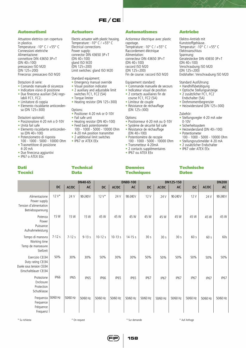
Automatismes
Actionneur électrique avec plastic capotage.Température: -10° C / +55° CRaccordement éléctriqueAlimentation: connecteur DIN 43650 3P+T(DN 40÷100)raccord ISO M20(DN 125÷200)Fin de course: raccord ISO M20
Equipement standard:• Commande manuelle de secours• Indicateur visual de position• 2 contacts auxiliaires fin de
course FC1, FC2 (5A)• Limiteur de couple• Résistance de réchauffage (DN 125÷300)
Options:• Positionneur 4-20 mA ou 0-10V• Système de sécurité fail safe• Résistance de réchauffage (DN 40÷100)• Potentiomètre de recopie 100 - 1000 - 5000 - 10000 Ohm• Transmetteur 4-20mA• 2 contacts supplémentaires• IP67 ou ATEX EEx
Automatismi
Attuatore elettrico con copertura in plastica.Temperatura: -10° C / +55° CConnessioni elettricheAlimentazione: connettore DIN 43650 3P+T(DN 40÷100)pressacavo ISO M20(DN 125÷200)Finecorsa: pressacavo ISO M20
Dotazioni di serie:• Comando manuale di sicurezza• Indicatore visivo di posizione• Due finecorsa ausiliari (5A) rego-
labili FC1, FC2.• Limitatore di coppia• Elemento riscaldante anticonden-
sa (DN 125÷300)
Dotazioni opzionali:• Posizionatore 4-20 mA o 0-10V• Unità fail safe• Elemento riscaldante anticonden-
sa (DN 40÷100)• Potenziometro di risposta 100 - 1000 - 5000 - 10000 Ohm • Trasmettitore di posizione 4-20 mA• Due finecorsa aggiuntivi• IP67 o ATEX EEx
Actuators
Electric actuator with plastic housing.Temperature: -10° C / +55° CElectrical connectionsPower supply: connector DIN 43650 3P+T(DN 40÷100)gland ISO M20(DN 125÷200)Limit switches: gland ISO M20
Standard equipment:• Emergency manual override• Visual position indicator• 2 auxiliary and adjustable limit
switches FC1, FC2 (5A)• Torque limiter• Heating resistor (DN 125÷300)
Options:• Positioner 4-20 mA or 0-10V• Fail safe unit• Heating resistor (DN 40÷100)• Feed back potentiometer 100 - 1000 - 5000 - 10000 Ohm • 4-20 mA position transmitter• 2 additional limit switches• IP67 or ATEX EEx
Antriebe
Elektro-Antrieb mit Kunststoffgehäuse.Temperatur: -10° C / +55° CElektroanschlussSpannung: Geratestecker DIN 43650 3P+T(DN 40÷100)Verschraubung ISO M20(DN 125÷200)Endshalter: Verschraubung ISO M20
Standard Ausführung:• Handhilfsbetätigung• Optische Stellungsanzeige• 2 zusätzlicher FC1, FC2
Endschalter (5A)• Drehmomentbegrenzier• Heizwiderstand (DN 125÷300)
Zubehör:• Stellungsregler 4-20 mA oder
0-10V• Sicherheitssystem• Heizwiderstand (DN 40÷100)• Potentiometer 100 - 1000 - 5000 - 10000 Ohm• Stellungsruckmelder 4-20 mA• 2 zusätzlicher Endschalter• IP67 oder ATEX EEx
TechnischeDaten
AlimentazionePower supply
Tension d’alimentationBetriebsspannung
PotenzaPower
Puissance Aufnahmeleistung
Tempo di manovraWorking time
Temp de manoeuvre Stellzeit
Esercizio CEI34Duty rating CEI34
Durée sous tension CEI34Einschaltdauer CEI34
ProtezioneEnclosureProtection
Schutklasse
FrequenzaFrequenceFréquenceFrequenz
DN200AC
90-240 V
45 W
60s
50%
IP67
50/60 Hz
DN125-150AC
90-240 V
45 W
30 s
50%
IP67
50/60 Hz
DN80-100AC
90-240 V
45 W
14-15 s
30%
IP65
50/60 Hz
DC
12 V*
45 W
10-12 s
50%
IP66
50/60 Hz
DC
12 V
45 W
30 s
50%
IP67
50/60 Hz
DC
12 V
45 W
60 s
50%
IP67
50/60 Hz
DC
12 V*
15 W
7-12 s
50%
IP66
50/60 Hz
* On request * Sur demande* Su richiesta * Auf Anfrage
DN40-65AC
90-240 V
15 W
9-13 s
30%
IP65
50/60 Hz
AC/DC
24 V
15 W
7-12 s
30%
IP65
50/60 Hz
AC/DC
24 V
45 W
10-13 s
30%
IP65
50/60 Hz
AC/DC
24 V
45 W
30 s
50%
IP67
50/60 Hz
AC/DC
24 V
45 W
60 s
50%
IP67
50/60 Hz
FE / CE
159
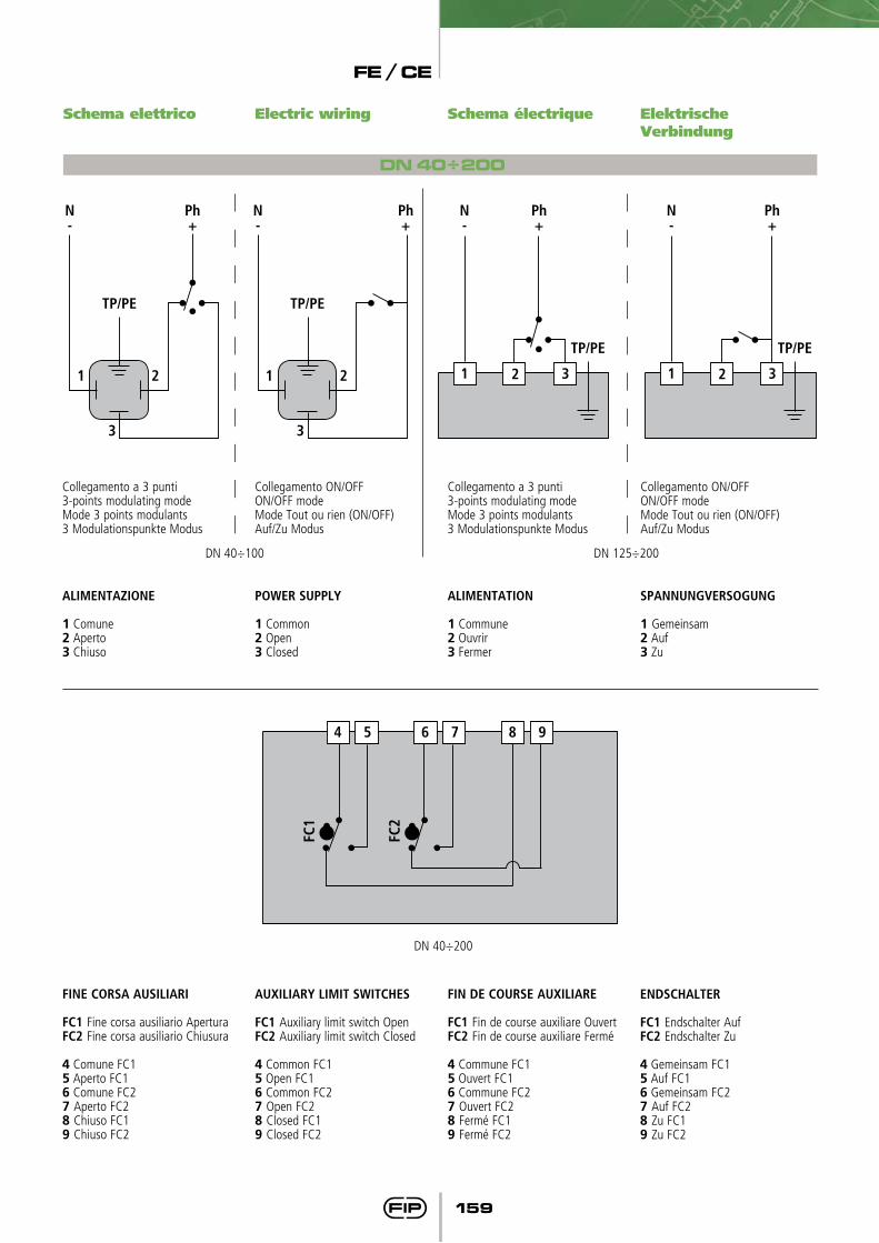
Schema électriqueSchema elettrico Electric wiring Elektrische Verbindung
DN 40÷200
ALiMENTAZiONE
1 Comune2 Aperto3 Chiuso
ALiMENTATiON
1 Commune 2 Ouvrir3 Fermer
POwER SUPPLy
1 Common2 Open3 Closed
SPANNUNGVERSOGUNG
1 Gemeinsam2 Auf3 Zu
Collegamento a 3 punti3-points modulating modeMode 3 points modulants3 Modulationspunkte Modus
Collegamento a 3 punti3-points modulating modeMode 3 points modulants3 Modulationspunkte Modus
Collegamento ON/OFFON/OFF modeMode Tout ou rien (ON/OFF)Auf/Zu Modus
Collegamento ON/OFFON/OFF modeMode Tout ou rien (ON/OFF)Auf/Zu Modus
1
3
2
Ph+
N-
TP/PE
1
3
2
Ph+
N-
TP/PE
Ph+
N-
TP/PE
1 32
Ph+
N-
TP/PE
1 32
DN 40÷100 DN 125÷200
FiNE CORSA AUSiLiARi
FC1 Fine corsa ausiliario AperturaFC2 Fine corsa ausiliario Chiusura
4 Comune FC15 Aperto FC16 Comune FC27 Aperto FC28 Chiuso FC19 Chiuso FC2
FiN DE COURSE AUxiLiARE
FC1 Fin de course auxiliare OuvertFC2 Fin de course auxiliare Fermé
4 Commune FC15 Ouvert FC16 Commune FC27 Ouvert FC28 Fermé FC19 Fermé FC2
AUxiLiARy LiMiT SwiTCHES
FC1 Auxiliary limit switch OpenFC2 Auxiliary limit switch Closed
4 Common FC15 Open FC16 Common FC27 Open FC28 Closed FC19 Closed FC2
ENDSCHALTER
FC1 Endschalter AufFC2 Endschalter Zu
4 Gemeinsam FC15 Auf FC16 Gemeinsam FC27 Auf FC28 Zu FC19 Zu FC2
DN 40÷200
4 5 6 7 8 9
FC1
FC2

FE / CE
160
VerbindungenVor Montage der FE Absperrklappenist zu überprüfen, ob die Bundbuchsen ein vollständiges öffnen der Klappenscheibe ermögli-chen. (I min-Maß beachten)
GiunzioniPrima di effettuare l’installazionedella valvola FE è opportunoverificare che il diametro di passag-gio della cartella consenta la corretta apertura del disco. (vedi I min)
Per l’installazione con collari in PVC-U vedi nella seguente Tab. B gli accoppiamenti valvola-collare-flangia.
JointingBefore installing the FE valve itis suggested to check that stubinternal diameter allows the com-plete disc opening. (see, I min)
For installation with PVC-U stubs please see in the Tab. B below the possible couplings valve-stub-flange.
JonctionAvant d’effectuer l’installationde la vanne FE il est conseillé devérifier que le diametre interieurdu collet permette l’ouverture duPapillon. (voir I min)
Pour installation avec collet PVC-U verifier dans le suivant Tab. B les accouplements vanne-collet-bride.
Für die Montage mit PVC-U Bundbuchsen siehe die möglichen Verbindungen gemaß Tab. B.
d
50637590
110140160225
DN
40506580
100125150200
i min.
2528476484
108134187
Collare d’appoggio incollaggio femmina e flangia DIN 8063-T4 - Stub female solvent welding and flange DIN 8063-T4Collet female a collèr and bride DIN 8063-T4 - Bundbuchse Klebemuffe und Flansch nach DIN 8063-T4
d
50
63
75
90
110
140
160
225
50
40
63
50
75
65
90
80
110
100
125
110
*
140
125
160
150
200
200
**
225
200DN
40
50
65
80
100
125
150
200Valvo
la F
E -
FE V
alve
FE v
anne
- FE
Abs
perrk
lapp
e
Tab. B
* Con collare speciale d125 DN125 per FE d140 DN125 e flangia d140 DN125** Con collare speciale d200 DN200 per FE d225 DN200 e flangia d225 DN200
* With special stub d125 DN125 for FE d140 DN125 to be mounted with flange d140 DN125** With special stub d200 DN200 for FE d225 DN200 to be mounted with flange d225 DN200
* Avec collet d’adaptation special d125 DN125 pour FE d140 DN125 et bride d140 DN125** Avec collet d’adaptation special d200 DN200 pour FE d225 DN200 et bride d225 DN200
* Mit spezieller Adapterbundbuchse d125 DN125 für FE d140 DN125 und Flansche d140 DN125** Mit spezieller Adapterbundbuchse d200 DN200 für FE d225 DN200 und Flansche d225 DN200
FE / CE
161
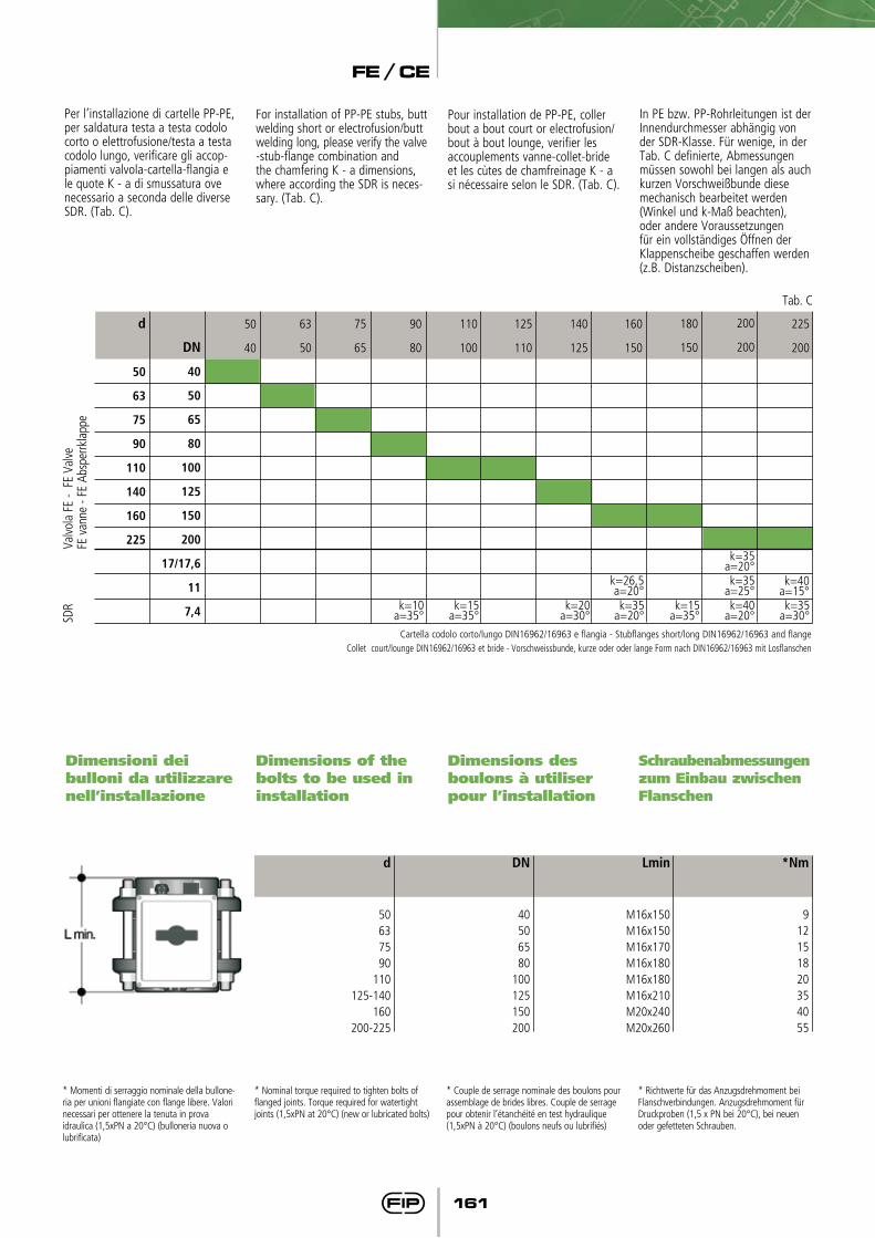
Per l’installazione di cartelle PP-PE, per saldatura testa a testa codolo corto o elettrofusione/testa a testa codolo lungo, verificare gli accop-piamenti valvola-cartella-flangia e le quote K - a di smussatura ove necessario a seconda delle diverse SDR. (Tab. C).
For installation of PP-PE stubs, butt welding short or electrofusion/butt welding long, please verify the valve-stub-flange combination and the chamfering K - a dimensions, where according the SDR is neces-sary. (Tab. C).
Pour installation de PP-PE, coller bout a bout court or electrofusion/bout à bout lounge, verifier les accouplements vanne-collet-bride et les cùtes de chamfreinage K - a si nécessaire selon le SDR. (Tab. C).
In PE bzw. PP-Rohrleitungen ist der Innendurchmesser abhängig von der SDR-Klasse. Für wenige, in der Tab. C definierte, Abmessungen müssen sowohl bei langen als auch kurzen Vorschweißbunde diese mechanisch bearbeitet werden (Winkel und k-Maß beachten), oder andere Voraussetzungen für ein vollständiges öffnen der Klappenscheibe geschaffen werden (z.B. Distanzscheiben).
Dimensioni deibulloni da utilizzare nell’installazione
Dimensions of thebolts to be used ininstallation
Dimensions desboulons à utiliserpour l’installation
Schraubenabmessungen zum Einbau zwischenFlanschen
d
50637590
110125-140
160200-225
DN
40506580
100125150200
Lmin
M16x150M16x150M16x170M16x180M16x180M16x210M20x240M20x260
*Nm
912151820354055
* Momenti di serraggio nominale della bullone-ria per unioni flangiate con flange libere. Valori necessari per ottenere la tenuta in provaidraulica (1,5xPN a 20°C) (bulloneria nuova o lubrificata)
* Nominal torque required to tighten bolts of flanged joints. Torque required for watertight joints (1,5xPN at 20°C) (new or lubricated bolts)
* Couple de serrage nominale des boulons pour assemblage de brides libres. Couple de serrage pour obtenir l’étanchéité en test hydraulique (1,5xPN à 20°C) (boulons neufs ou lubrifiés)
* Richtwerte für das Anzugsdrehmoment bei Flanschverbindungen. Anzugsdrehmoment fürDruckproben (1,5 x PN bei 20°C), bei neuen oder gefetteten Schrauben.
Cartella codolo corto/lungo DIN16962/16963 e flangia - Stubflanges short/long DIN16962/16963 and flangeCollet court/lounge DIN16962/16963 et bride - Vorschweissbunde, kurze oder oder lange Form nach DIN16962/16963 mit Losflanschen
d
50
63
75
90
110
140
160
225
50
40
63
50
75
65
90
80
110
100
125
110
140
125
160
150
180
150
200
200
225
200DN
40
50
65
80
100
125
150
200
17/17,6
11
7,4
Valvo
la F
E -
FE V
alve
FE v
anne
- FE
Abs
perrk
lapp
eSD
R
Tab. C
k=10a=35°
k=15a=35°
k=20a=30°
k=26,5a=20°k=35
a=20°
k=40a=15°k=35
a=30°
k=35a=25°
k=35a=20°
k=40a=20°
k=15a=35°
FE / CE
162
Connection to the system
Einbau in eine Leitung
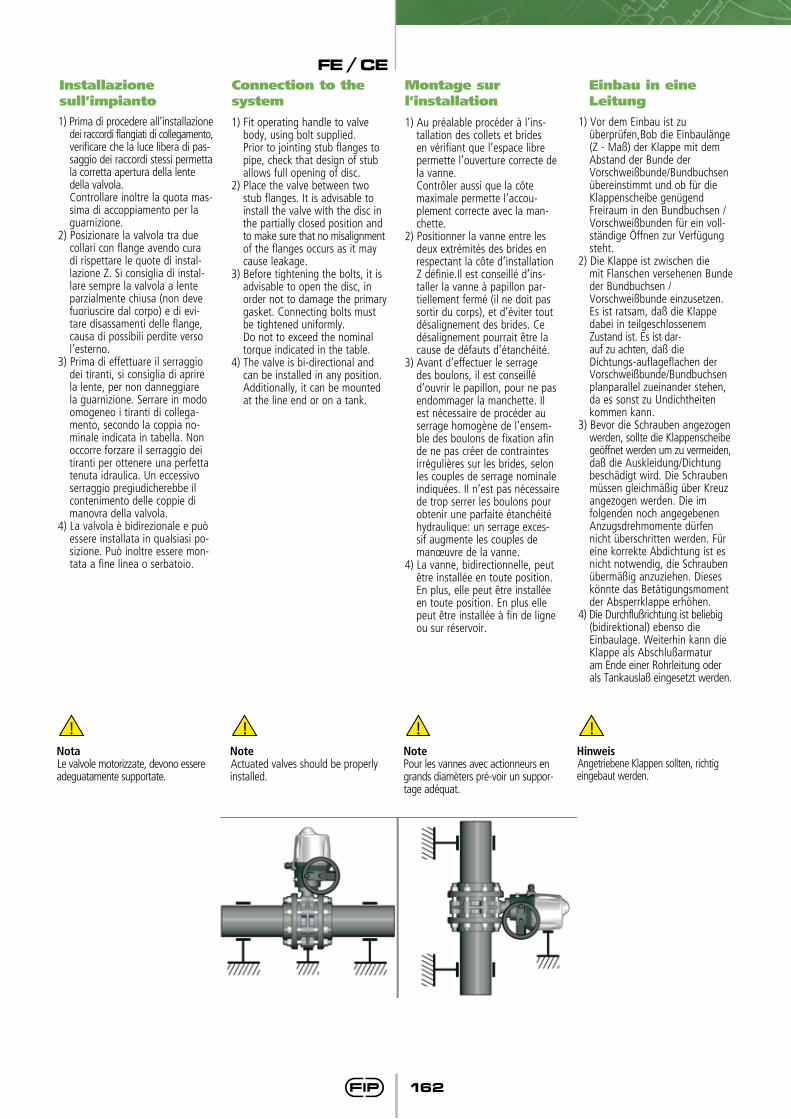
Installazione sull’impianto1) Prima di procedere all’installazione
dei raccordi flangiati di collegamento, verificare che la luce libera di pas-saggio dei raccordi stessi permetta la corretta apertura della lente della valvola.
Controllare inoltre la quota mas-sima di accoppiamento per la guarnizione.
2) Posizionare la valvola tra due collari con flange avendo cura di rispettare le quote di instal-lazione Z. Si consiglia di instal-lare sempre la valvola a lente parzialmente chiusa (non deve fuoriuscire dal corpo) e di evi-tare disassamenti delle flange, causa di possibili perdite verso l’esterno.
3) Prima di effettuare il serraggio dei tiranti, si consiglia di aprire
la lente, per non danneggiare la guarnizione. Serrare in modo omogeneo i tiranti di collega-mento, secondo la coppia no-minale indicata in tabella. Non occorre forzare il serraggio dei tiranti per ottenere una perfetta tenuta idraulica. Un eccessivo serraggio pregiudicherebbe il contenimento delle coppie di manovra della valvola.
4) La valvola è bidirezionale e può essere installata in qualsiasi po-sizione. Può inoltre essere mon-tata a fine linea o serbatoio.
1) Fit operating handle to valve body, using bolt supplied.
Prior to jointing stub flanges to pipe, check that design of stub allows full opening of disc.
2) Place the valve between two stub flanges. It is advisable to install the valve with the disc in
the partially closed position and to make sure that no misalignment
of the flanges occurs as it may cause leakage.
3) Before tightening the bolts, it is advisable to open the disc, in
order not to damage the primary gasket. Connecting bolts must be tightened uniformly.
Do not to exceed the nominal torque indicated in the table.4) The valve is bi-directional and can be installed in any position. Additionally, it can be mounted at the line end or on a tank.
Montage sur l’installation
1) Au préalable procéder à l’ins-tallation des collets et brides en vérifiant que l’espace libre permette l’ouverture correcte de la vanne.
Contrôler aussi que la côte maximale permette l’accou-plement correcte avec la man-chette.
2) Positionner la vanne entre les deux extrémités des brides en respectant la côte d’installation Z définie.Il est conseillé d’ins-taller la vanne à papillon par-tiellement fermé (il ne doit pas sortir du corps), et d’éviter tout désalignement des brides. Ce
désalignement pourrait être la cause de défauts d’étanchéité.3) Avant d’effectuer le serrage
des boulons, il est conseillé d’ouvrir le papillon, pour ne pas endommager la manchette. Il est nécessaire de procéder au serrage homogène de l’ensem-ble des boulons de fixation afin de ne pas créer de contraintes irrégulières sur les brides, selon les couples de serrage nominale indiquées. Il n’est pas nécessaire de trop serrer les boulons pour obtenir une parfaite étanchéité hydraulique: un serrage exces-sif augmente les couples de manœuvre de la vanne.
4) La vanne, bidirectionnelle, peut être installée en toute position. En plus, elle peut être installée en toute position. En plus elle peut être installée à fin de ligne
ou sur réservoir.
1) Vor dem Einbau ist zu überprüfen,Bob die Einbaulänge
(Z - Maß) der Klappe mit dem Abstand der Bunde der
Vorschweißbunde/Bundbuchsen übereinstimmt und ob für die Klappenscheibe genügend Freiraum in den Bundbuchsen / Vorschweißbunden für ein voll-ständige öffnen zur Verfügung steht.
2) Die Klappe ist zwischen die mit Flanschen versehenen Bunde
der Bundbuchsen / Vorschweißbunde einzusetzen. Es ist ratsam, daß die Klappe
dabei in teilgeschlossenem Zustand ist. Es ist dar-
auf zu achten, daß die Dichtungs-auflageflachen der Vorschweißbunde/Bundbuchsen planparallel zueinander stehen,
da es sonst zu Undichtheiten kommen kann.3) Bevor die Schrauben angezogen werden, sollte die Klappenscheibe
geöffnet werden um zu vermeiden, daß die Auskleidung/Dichtung beschädigt wird. Die Schrauben müssen gleichmäßig über Kreuz angezogen werden. Die im folgenden noch angegebenen Anzugsdrehmomente dürfen nicht überschritten werden. Für eine korrekte Abdichtung ist es nicht notwendig, die Schrauben übermäßig anzuziehen. Dieses könnte das Betätigungsmoment der Absperrklappe erhöhen.
4) Die Durchflußrichtung ist beliebig (bidirektional) ebenso die
Einbaulage. Weiterhin kann die Klappe als Abschlußarmatur
am Ende einer Rohrleitung oder als Tankauslaß eingesetzt werden.
NotaLe valvole motorizzate, devono essere adeguatamente supportate.
NoteActuated valves should be properly installed.
NotePour les vannes avec actionneurs en grands diamèters pré-voir un suppor-tage adéquat.
HinweisAngetriebene Klappen sollten, richtig eingebaut werden.
FE / CE
163
6) Einbaulage (Winkel der Klappenwelle zur Waagerechten) in Abhängigkeit des Zustandes des zu fördernden Mediums:
- Medium stark verschmutzt min. 45°.
- Medium mit Schwebepartikeln waagerecht.
- Medium nicht verunreinigt senkrecht.
6) Si consiglia di rispettare le se-guenti precauzioni:
- Convogliamento di fluidi non puli-ti: posizionamento con lo stelo di manovra inclinato di un angolo di 45° rispetto al piano di appoggio della tubazione.
- Convogliamento fluidi con sedi-menti: posizionare la valvola con lo stelo di manovra parallelo al piano di appoggio della tubazione.
- Convogliamento fluidi puliti: po-sizionare la valvola con lo stelo di manovra perpendicolare al piano di appoggio della tubazione.
6) If the medium to be conveyed is:- Dirty: it is advisable to install the
valve with the manoeuvring stem at a position of a minimum 45° angle to the pipe.
- With suspended particles: it is advisable to install the valve with the manoeuvring stem just parallel to the pipe.
- Just clean: it is advisable to install the valve with the ma-
noeuvring stem at a position of 90° angle to the pipe.
6) Il est conseillé de monter la vanne avec tige de manœuvre dans les positions suivantes:
- Si le fluide qui doit être transporté est chargé: avec un angle de 45° minimum entre la tige et le tube.
- Si le fluide qui doit être transporté a des particules en suspension: parallèlement au tube.
- Si le fluide qui doit être transporté est propre: perpendiculairement au tube.
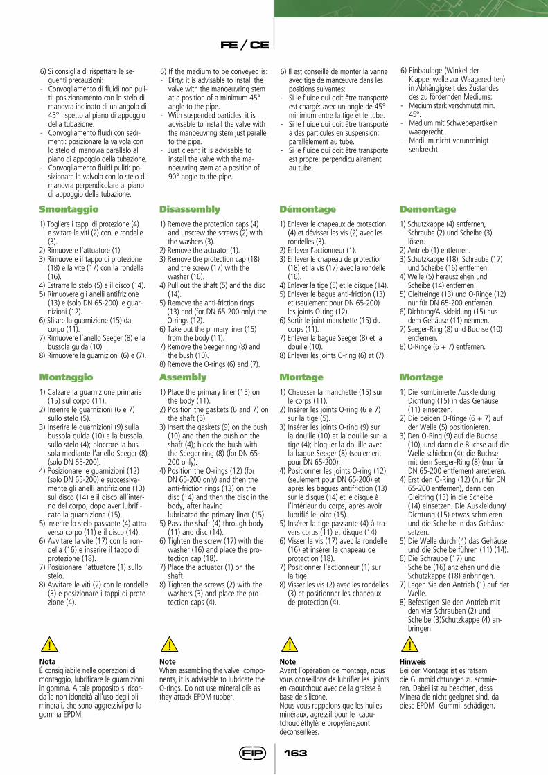
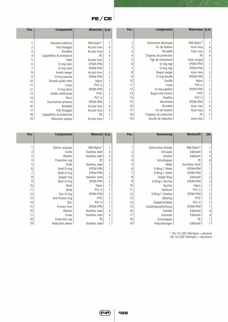
Smontaggio
1) Togliere i tappi di protezione (4) e svitare le viti (2) con le rondelle (3).
2) Rimuovere l’attuatore (1).3) Rimuovere il tappo di protezione
(18) e la vite (17) con la rondella (16).
4) Estrarre lo stelo (5) e il disco (14).5) Rimuovere gli anelli antifrizione
(13) e (solo DN 65-200) le guar-nizioni (12).
6) Sfilare la guarnizione (15) dal corpo (11).
7) Rimuovere l’anello Seeger (8) e la bussola guida (10).
8) Rimuovere le guarnizioni (6) e (7).
Disassembly
1) Remove the protection caps (4) and unscrew the screws (2) with the washers (3).
2) Remove the actuator (1).3) Remove the protection cap (18)
and the screw (17) with the washer (16).
4) Pull out the shaft (5) and the disc (14).
5) Remove the anti-friction rings (13) and (for DN 65-200 only) the O-rings (12).
6) Take out the primary liner (15) from the body (11).
7) Remove the Seeger ring (8) and the bush (10).
8) Remove the O-rings (6) and (7).
Démontage
1) Enlever le chapeaux de protection (4) et dévisser les vis (2) avec les rondelles (3).
2) Enlever l’actionneur (1).3) Enlever le chapeau de protection
(18) et la vis (17) avec la rondelle (16).
4) Enlever la tige (5) et le disque (14).5) Enlever le bague anti-friction (13)
et (seulement pour DN 65-200) les joints O-ring (12).
6) Sortir le joint manchette (15) du corps (11).
7) Enlever la bague Seeger (8) et la douille (10).
8) Enlever les joints O-ring (6) et (7).
Demontage
1) Schutzkappe (4) entfernen, Schraube (2) und Scheibe (3) lösen.
2) Antrieb (1) entfernen.3) Schutzkappe (18), Schraube (17)
und Scheibe (16) entfernen.4) Welle (5) herausziehen und
Scheibe (14) entfernen.5) Gleitreinge (13) und O-Ringe (12)
nur für DN 65-200 entfernen.6) Dichtung/Auskleidung (15) aus
dem Gehäuse (11) nehmen.7) Seeger-Ring (8) und Buchse (10)
entfernen.8) O-Ringe (6 + 7) entfernen.
Montaggio
1) Calzare la guarnizione primaria (15) sul corpo (11).
2) Inserire le guarnizioni (6 e 7) sullo stelo (5).
3) Inserire le guarnizioni (9) sulla bussola guida (10) e la bussola sullo stelo (4); bloccare la bus-sola mediante l’anello Seeger (8) (solo DN 65-200).
4) Posizionare le guarnizioni (12) (solo DN 65-200) e successiva-mente gli anelli antifrizione (13) sul disco (14) e il disco all’inter-no del corpo, dopo aver lubrifi-cato la guarnizione (15).
5) Inserire lo stelo passante (4) attra-verso corpo (11) e il disco (14).
6) Avvitare la vite (17) con la ron-della (16) e inserire il tappo di protezione (18).
7) Posizionare l‘attuatore (1) sullo stelo.
8) Avvitare le viti (2) con le rondelle (3) e posizionare i tappi di prote-zione (4).
Assembly
1) Place the primary liner (15) on the body (11).
2) Position the gaskets (6 and 7) on the shaft (5).
3) Insert the gaskets (9) on the bush (10) and then the bush on the shaft (4); block the bush with the Seeger ring (8) (for DN 65-200 only).
4) Position the O-rings (12) (for DN 65-200 only) and then the anti-friction rings (13) on the disc (14) and then the disc in the body, after having
lubricated the primary liner (15).5) Pass the shaft (4) through body
(11) and disc (14).6) Tighten the screw (17) with the
washer (16) and place the pro-tection cap (18).
7) Place the actuator (1) on the shaft.
8) Tighten the screws (2) with the washers (3) and place the pro-tection caps (4).
Montage
1) Chausser la manchette (15) sur le corps (11).
2) Insérer les joints O-ring (6 e 7) sur la tige (5).
3) Insérer les joints O-ring (9) sur la douille (10) et la douille sur la tige (4); bloquer la douille avec la bague Seeger (8) (seulement pour DN 65-200).
4) Positionner les joints O-ring (12) (seulement pour DN 65-200) et après les bagues antifriction (13) sur le disque (14) et le disque à l’intérieur du corps, après avoir lubrifié le joint (15).
5) Insérer la tige passante (4) à tra-vers corps (11) et disque (14)
6) Visser la vis (17) avec la rondelle (16) et insérer la chapeau de protection (18).
7) Positionner l‘actionneur (1) sur la tige.
8) Visser les vis (2) avec les rondelles (3) et positionner les chapeaux de protection (4).
Montage
1) Die kombinierte Auskleidung Dichtung (15) in das Gehäuse (11) einsetzen.
2) Die beiden O-Ringe (6 + 7) auf der Welle (5) positionieren.
3) Den O-Ring (9) auf die Buchse (10), und dann die Buchse auf die Welle schieben (4); die Buchse mit dem Seeger-Ring (8) (nur für DN 65-200 entfernen) arretieren.
4) Erst den O-Ring (12) (nur für DN 65-200 entfernen), dann den Gleitring (13) in die Scheibe (14) einsetzen. Die Auskleidung/Dichtung (15) etwas schmieren und die Scheibe in das Gehäuse setzen.
5) Die Welle durch (4) das Gehäuse und die Scheibe führen (11) (14).
6) Die Schraube (17) und Scheibe (16) anziehen und die Schutzkappe (18) anbringen.
7) Legen Sie den Antrieb (1) auf der Welle.
8) Befestigen Sie den Antrieb mit den vier Schrauben (2) und Scheibe (3)Schutzkappe (4) an-bringen.
Notaé consigliabile nelle operazioni di montaggio, lubrificare le guarnizioni in gomma. A tale proposito si ricor-da la non idoneità all’uso degli oli minerali, che sono aggressivi per la gomma EPDM.
NoteWhen assembling the valve compo-nents, it is advisable to lubricate the O-rings. Do not use mineral oils as they attack EPDM rubber.
NoteAvant l’opération de montage, nous vous conseillons de lubrifier les joints en caoutchouc avec de la graisse à base de silicone.Nous vous rappelons que les huiles minéraux, agressif pour le caou-tchouc éthylène propylène,sont déconseillées.
HinweisBei der Montage ist es ratsam die Gummidichtungen zu schmie-ren. Dabei ist zu beachten, dass Mineralöle nicht geeignet sind, da diese EPDM- Gummi schädigen.
FE / CE
164
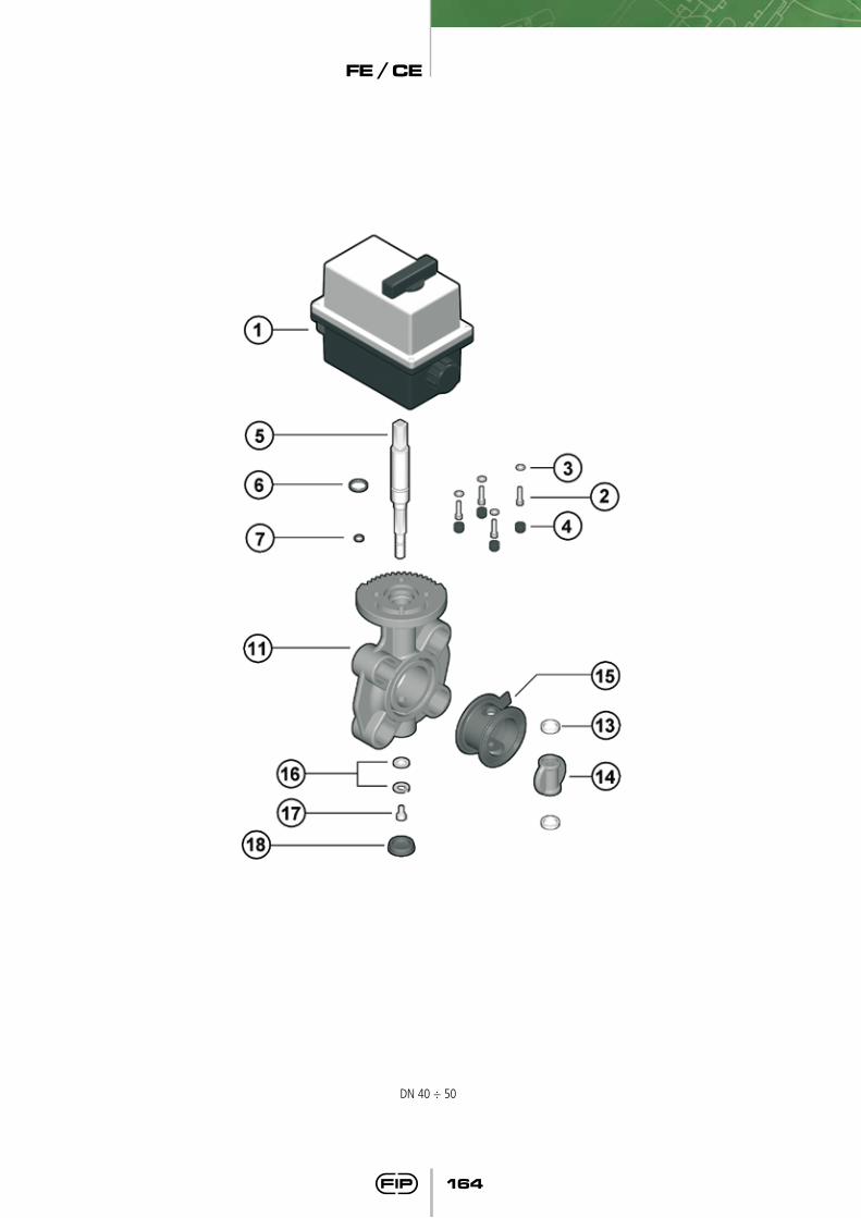
DN 40 ÷ 50
FE / CE
165
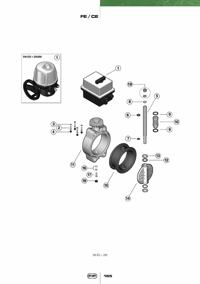
DN 65 ÷ 200
FE / CE
166
Pos.
123456789
10111213141516171819
Q.tà
1444111221122114411
Componenti
Attuatore elettricoVite fissaggio
RondellaCappellotto di protezione
SteloO-ring steloO-ring stelo
Anello seegerO-ring bussola
Bussola guida steloCorpo
O-ring discoAnello antifrizione
DiscoGuarnizione primaria
RondellaVite fissaggio
Cappellotto di protezioneRiduzione quadra
Materiale
PA6-Nylon*Acciaio inoxAcciaio inox
PEAcciaio inoxEPDM-FPMEPDM-FPM
Acciaio inoxEPDM-FPM
NylonPVC-U
EPDM-FPMPTFE
PVC-UEPDM-FPM
Acciaio inoxAcciaio inox
PEAcciaio inox
Pos.
123456789
10111213141516171819
Materiaux
PA6-Nylon*Acier inoxAcier inox
PEAcier zinguéEPDM-FPMEPDM-FPM
Acier inoxEPDM-FPM
NylonPVC-U
EPDM-FPMPTFE
PVC-UEPDM-FPM
Acier inoxAcier inox
PEAcier inox
Q.té
1444111221122114411
Composants
Actionneur electriqueVis de fixation
RondelleChapeau de protection
Tige de manoeuvreO-ring tigeO-ring tige
Bague seegerO-ring douille
DouilleCorps
O-ring papillonBague anti friction
PapillonManchette
RondelleVis de fixation
Chapeau de protectionDouille de reduction
Pos.
123456789
10111213141516171819
Components
Electric actuatorScrew
WasherProtection cap
Shaft Shaft O-ringShaft O-ringSeeger ringBush O-ring
BushBody
Disc O-ringAnti-friction ring
DiscPrimary liner
WasherScrew
Protection capReduction sleeve
Material
PA6-Nylon*Stainless steelStainless steel
PEStainless steel
EPDM-FPMEPDM-FPM
Stainless steelEPDM-FPM
NylonPVC-U
EPDM-FPMPTFE
PVC-UEPDM-FPM
Stainless steelStainless steel
PEStainless steel
Pos.
123456789
10111213141516171819
Benennung
Elektrischer-AntirebSchraube
ScheibeSchutzkappe
WelleO-Ring f. WelleO-Ring f. Welle
Seeger-RingO-Ring f. Buchse
BuchseGehäuse
O-Ring f. ScheibeGleitring
KlappenscheibeAuskleidung/Dichtung
ScheibeSchraube
SchutzkappeReduzierungen
werkstoff
PA6-Nylon*EdelstahlEdelstahl
PEVerzinkter Stahl
EPDM-FPMEPDM-FPM
EdelstahlEPDM-FPM
NylonPVC-U
EPDM-FPMPTFE
PVC-UEPDM-FPM
EdelstahlEdelstahl
PEEdelstahl
Q.ty
1444111221122114411
Stk
1444111221122114411
* DN 125-200: PA6-Nylon + alluminioDN 125-200: PA6-Nylon + Aluminium
Code
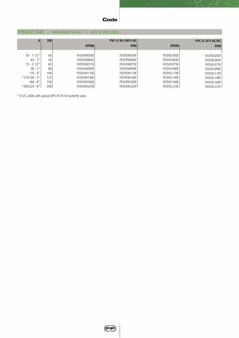
FEOV/CE - 90-240 V AC - 24 V AC/DC
DN
40506580
100125150200
PVC-U 24 V AC/DC FPM
FEOVEL050FFEOVEL063FFEOVEL075FFEOVEL090FFEOVEL110FFEOVEL140FFEOVEL160FFEOVEL225F
PVC-U 90-240 V AC
FPM
FEOVEM050FFEOVEM063FFEOVEM075FFEOVEM090FFEOVEM110FFEOVEM140FFEOVEM160FFEOVEM225F
EPDM
FEOVEM050EFEOVEM063EFEOVEM075EFEOVEM090EFEOVEM110EFEOVEM140EFEOVEM160EFEOVEM225E
EPDM
FEOVEL050EFEOVEL063EFEOVEL075EFEOVEL090EFEOVEL110EFEOVEL140EFEOVEL160EFEOVEL225E
d
50 - 1 1/2”63 - 2”
75 - 2 1/2”90 - 3”
110 - 4” *125/140 - 5”
160 - 6”*200/225 - 8”
* d125, d200 with special QPV FE-FK for butterfly valve


![DSC Diffusori circolari a coni fissi - Barcol-Air Group …...DSC Diffusori circolari a coni fissi Legenda Q [m3/h] oder [l/s] portata d’aria immessa ØN [mm] diametro nominale del](https://static.fdocuments.net/doc/165x107/5fa56c3f1d9cc41dbe72d871/dsc-diffusori-circolari-a-coni-fissi-barcol-air-group-dsc-diffusori-circolari.jpg)
