Validation of Space-Based Polarization Measurements by Use of a Single-Scattering Approximation,...
10
Validation of space-based polarization measurements by use of a single-scattering approximation, with application to the Global Ozone Monitoring Experiment Ilse Aben, Cristina P. Tanzi, Wouter Hartmann, Daphne M. Stam, and Piet Stammes A method is presented for in-flight validation of space-based polarization measurements based on approximation of the direction of polarization of scattered sunlight by the Rayleigh single-scattering value. This approximation is verified by simulations of radiative transfer calculations for various atmospheric conditions. The simulations show locations along an orbit where the scattering geometries are such that the intensities of the parallel and orthogonal polarization components of the light are equal, regardless of the observed atmosphere and surface. The method can be applied to any space-based instrument that measures the polarization of reflected solar light. We successfully applied the method to validate the Global Ozone Monitoring Experiment GOME polarization measurements. The error in the GOME’s three broadband polarization measurements appears to be 1%. © 2003 Optical Society of America OCIS codes: 010.0010, 010.1280, 280.0280. 1. Introduction Satellite-based passive remote sensing is commonly used to derive global information about the composi- tion of the Earth’s atmosphere. One can obtain geo- physical quantities such as total ozone columns and ozone vertical profiles by measuring the radiance in- tensity spectrum of sunlight reflected by the Earth’s atmosphere, as this spectrum contains absorption bands of trace gases. The Global Ozone Monitoring Experiment GOME is an example of an operational space-based spectrometer that measures the radi- ance of reflected sunlight in the ultraviolet–visible wavelength range 240–800 nm with modest spec- tral resolution 0.2– 0.4 nm. 1 The GOME is on- board the European Space Agency’s second European Remote Sensing satellite ERS-2, which was launched on 21 April 1995. Although direct, unscattered sunlight is unpolar- ized, the sunlight reflected by the Earth’s atmosphere is generally polarized because of scattering by atmo- spheric gaseous molecules and aerosol particles. Studies 2–6 have shown that the degree of polarization of reflected sunlight contains information on the at- mospheric composition. However, for an instru- ment such as the GOME, which aims at measuring the radiance of reflected sunlight, the polarization of this light is considered a nuisance. That is, the GOME, in particular, but also some of its successors such as the Scanning Imaging Absorption Spectrom- eter for Atmospheric Chartography SCIAMACHY on the Environmental Satellite ENVISAT launched in 2002 and GOME-2 on the European Organization for Exploitation of Meteorological Satellites EUMET- SAT’s Metop series planned launches in 2005, 2010, and 2015, are highly polarization sensitive instru- ments because of the instruments’ gratings and mir- rors, which have polarization-dependent reflectivity. For example, Fig. 1 shows GOME’s polarization sen- sitivity as the ratio of the instrument’s sensitivity to When this research was performed, I. Aben [email protected], C. P. Tanzi, W. Hartmann, and D. M. Stam were with the National Institute for Space Research, Sorbonnelaan 2, 3584 CA Utrecht, The Netherlands. P. Stammes was with the Royal Netherlands Meteorological Institute, P.O. Box 201, 3730 AE De Bilt, The Neth- erlands. C. P. Tanzi is now with the Netherlands Environmental Assessment Agency, P.O. Box 1, 3720 BA Bilthoven, The Nether- lands. D. M. Stam is now with the Astronomical Institute Anton Pannekoek, University of Amsterdam, Kruislaan 403, 1098 SJ Amsterdam, The Netherlands. Received 20 August 2002; revised manuscript received 17 Feb- ruary 2003. 0003-693503183610-10$15.000 © 2003 Optical Society of America 3610 APPLIED OPTICS Vol. 42, No. 18 20 June 2003
Transcript of Validation of Space-Based Polarization Measurements by Use of a Single-Scattering Approximation,...
Validation of space-based polarizationmeasurements by use of a single-scatteringapproximation, with application to the GlobalOzone Monitoring Experiment
Ilse Aben, Cristina P. Tanzi, Wouter Hartmann, Daphne M. Stam, and Piet Stammes
A method is presented for in-flight validation of space-based polarization measurements based onapproximation of the direction of polarization of scattered sunlight by the Rayleigh single-scatteringvalue. This approximation is verified by simulations of radiative transfer calculations for variousatmospheric conditions. The simulations show locations along an orbit where the scattering geometriesare such that the intensities of the parallel and orthogonal polarization components of the light are equal,regardless of the observed atmosphere and surface. The method can be applied to any space-basedinstrument that measures the polarization of reflected solar light. We successfully applied the methodto validate the Global Ozone Monitoring Experiment �GOME� polarization measurements. The error inthe GOME’s three broadband polarization measurements appears to be �1%. © 2003 Optical Society ofAmerica
OCIS codes: 010.0010, 010.1280, 280.0280.
1. Introduction
Satellite-based passive remote sensing is commonlyused to derive global information about the composi-tion of the Earth’s atmosphere. One can obtain geo-physical quantities such as total ozone columns andozone vertical profiles by measuring the radiance �in-tensity� spectrum of sunlight reflected by the Earth’satmosphere, as this spectrum contains absorptionbands of trace gases. The Global Ozone MonitoringExperiment �GOME� is an example of an operationalspace-based spectrometer that measures the radi-ance of reflected sunlight in the ultraviolet–visible
When this research was performed, I. Aben �[email protected]�,C. P. Tanzi, W. Hartmann, and D. M. Stam were with the NationalInstitute for Space Research, Sorbonnelaan 2, 3584 CA Utrecht,The Netherlands. P. Stammes was with the Royal NetherlandsMeteorological Institute, P.O. Box 201, 3730 AE De Bilt, The Neth-erlands. C. P. Tanzi is now with the Netherlands EnvironmentalAssessment Agency, P.O. Box 1, 3720 BA Bilthoven, The Nether-lands. D. M. Stam is now with the Astronomical Institute AntonPannekoek, University of Amsterdam, Kruislaan 403, 1098SJ Amsterdam, The Netherlands.
Received 20 August 2002; revised manuscript received 17 Feb-ruary 2003.
0003-6935�03�183610-10$15.00�0© 2003 Optical Society of America
3610 APPLIED OPTICS � Vol. 42, No. 18 � 20 June 2003
wavelength range �240–800 nm� with modest spec-tral resolution �0.2–0.4 nm�.1 The GOME is on-board the European Space Agency’s second EuropeanRemote Sensing satellite �ERS-2�, which waslaunched on 21 April 1995.
Although direct, unscattered sunlight is unpolar-ized, the sunlight reflected by the Earth’s atmosphereis generally polarized because of scattering by atmo-spheric gaseous molecules and aerosol particles.Studies2–6 have shown that the degree of polarizationof reflected sunlight contains information on the at-mospheric composition. However, for an instru-ment such as the GOME, which aims at measuringthe radiance of reflected sunlight, the polarization ofthis light is considered a nuisance. That is, theGOME, in particular, but also some of its successorssuch as the Scanning Imaging Absorption Spectrom-eter for Atmospheric Chartography �SCIAMACHY�on the Environmental Satellite ENVISAT �launchedin 2002� and GOME-2 on the European Organizationfor Exploitation of Meteorological Satellites EUMET-SAT’s Metop series �planned launches in 2005, 2010,and 2015�, are highly polarization sensitive instru-ments because of the instruments’ gratings and mir-rors, which have polarization-dependent reflectivity.For example, Fig. 1 shows GOME’s polarization sen-sitivity as the ratio of the instrument’s sensitivity to

light polarized perpendicularly to the instrument’sslit to the sensitivity to parallel-polarized light. Ne-glect of such an instrument’s polarization sensitivitycan lead to errors of several tens of percent in thevalues of radiance measured at wavelengths wherethe instrument’s polarization sensitivity is highest.To account for the instrument’s polarization sensitiv-ity, the GOME measures the polarization of reflectedsunlight by using three broadband detectors.
In this paper we present a method for validat-ing space-based polarization measurements. Themethod is based on approximation of the direction ofpolarization of scattered sunlight by the Rayleighsingle-scattering value. At specific locations along aGOME orbit the scattering geometries are such thatthe Rayleigh single-scattering direction of polariza-tion is 45° or 135°. At these locations the radiance ofthe parallel and of the orthogonal polarization com-ponents of the reflected light should be equal. Weuse deviations from the predicted behavior at theselocations to assess the systematic errors in the polar-ization measurements.
In principle, the method can be applied to anyspace-based instrument that measures the polariza-tion of reflected sunlight, such as Polarization andDirectionality of the Earth’s Reflectances �POLDER�,SCIAMACHY, and GOME-2. We apply the methodto GOME polarization measurements to illustratethe validity of the method while at the same timeproviding a quantitative validation of the GOME po-larization measurements.
The structure of this paper is as follows: InSection 2 we describe the polarization characteristicsof reflected sunlight. The polarization-validationmethod is introduced in Section 3. The results of thevalidation method obtained with GOME data are pre-sented in Section 4, followed by our conclusions inSection 5. The appendixes give a more detailed de-scription of the GOME measurements and the GOME
polarization-correction algorithm that is used to cor-rect the measured radiances for the GOME’s polar-ization sensitivity.
2. Polarization of Reflected Sunlight
Although direct, unscattered sunlight is unpolarized,sunlight reflected by the Earth’s atmosphere is gen-erally polarized because of scattering by atmosphericgaseous molecules and aerosol particles. Linearlypolarized light can be described by the Stokes param-eters I, Q, and U, which are defined, relative to anyreference plane, as follows8:
I � I0° � I90°, (1)
Q � I0° � I90°, (2)
U � I45° � I135°, (3)
where I is the total intensity and Q and U fully rep-resent the linear polarization. In Eqs. �1�–�3� theangles denote the direction of the transmission axis ofa linear polarizer relative to the reference plane.The degree of linear polarization P is given by8
P � �Q2 � U 2�1�2�I (4)
and the direction of polarization � relative to thereference plane is given by
tan 2� � U�Q. (5)
For the unique definition of �, see Appendix C. Inwhat follows, we choose the local meridian plane, i.e.,the plane that contains the local zenith and the view-ing direction, as the reference plane. The GOMEinstrument is a nadir-looking across-track scanninginstrument �see Appendix A�. Because the scan di-rection is in the instrument’s optical plane, the localmeridian plane coincides with the instrument’s opti-cal plane. Note that the amount of circularly polar-ized light reflected by the Earth’s atmosphere isnegligible,9 and therefore only linearly polarized lightis considered here.
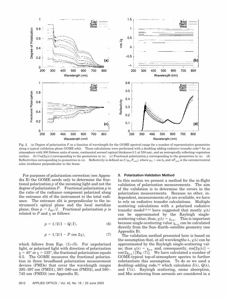
The degree of polarization P��� is a quantity thatcan vary drastically with wavelength and scene.10,11
Examples of this phenomenon for cloud-free atmo-spheres are shown in Fig. 2�a�. At wavelengths be-low 300 nm the radiation arises predominantly fromsingle Rayleigh scattering by molecules, because ofthe strong absorption by ozone that suppresses mul-tiple Rayleigh scattering. Single Rayleigh scatter-ing yields a high degree of polarization. Withincreasing wavelength the polarization drops be-cause ozone absorption decreases, and multiple Ray-leigh scattering becomes more important. However,beyond � � 320 nm, where ozone absorption is weak,the degree of polarization increases again becausethere is less multiple Rayleigh scattering as a resultof the decrease in the Rayleigh scattering opticalthickness. At still larger wavelengths the polariza-tion decreases because of the small effect of Rayleighscattering compared with the �depolarizing� effect ofscattering by aerosols and reflection by the surface.
Fig. 1. Ratio ��� of GOME instrument sensitivity for the twoorthogonal polarization components as a function of wavelengthand per channel for Nadir observations.7 For a polarization-insensitive instrument, � � 1.
20 June 2003 � Vol. 42, No. 18 � APPLIED OPTICS 3611
For purposes of polarization correction �see Appen-dix B� the GOME needs only to determine the frac-tional polarization p of the incoming light and not thedegree of polarization P. Fractional polarization p isthe ratio of the radiance component polarized alongthe entrance slit of the instrument to the total radi-ance. The entrance slit is perpendicular to the in-strument’s optical plane and the local meridianplane; thus p � I90°�I. Fractional polarization p isrelated to P and � as follows:
p � 1�2�1 � Q�I�, (6)
p � 1�2�1 � P cos 2��, (7)
which follows from Eqs. �1�–�5�. For unpolarizedlight, or polarized light with direction of polarization� � 45° or � � 135°, the fractional polarization equals0.5. The GOME measures the fractional polariza-tion in three broadband polarization measurementdevices �PMDs� that cover the wavelength ranges295–397 nm �PMD1�, 397–580 nm �PMD2�, and 580–745 nm �PMD3� �see Appendix B�.
3. Polarization-Validation Method
In this section we present a method for the in-flightvalidation of polarization measurements. The aimof the validation is to determine the errors in thepolarization measurements. Because no other, in-dependent, measurements of p are available, we haveto rely on radiative transfer calculations. Multiplescattering calculations with a polarized radiativetransfer model13,14 have suggested that mostly ����can be approximated by the Rayleigh single-scattering value; thus, ���� � �s.s.. This is importantbecause single-scattering value �s.s. can be calculateddirectly from the Sun–Earth–satellite geometry �seeAppendix B�.
The validation method presented here is based onthe assumption that, at all wavelengths �, ���� can beapproximated by the Rayleigh single-scattering val-ue; thus ���� � �s.s. and, consequently, cos�2���� �cos�2�s.s.� �Eq. �7�. We have calculated a number ofGOME-typical top-of-atmosphere spectra to furthersubstantiate this assumption. To do so we used adoubling–adding code,12 which calculates I���, Q���,and U���. Rayleigh scattering, ozone absorption,and Mie scattering from aerosols are considered in a
Fig. 2. �a� Degree of polarization P as a function of wavelength for the GOME spectral range for a number of representative geometriesalong a typical validation phase GOME orbit. These calculations were performed with a doubling adding radiative transfer code12 for anatmosphere with 300 Dobson units of ozone, continental aerosol �optical thickness 0.1 at 550 nm�, and an isotropically reflecting vegetationsurface. �b� Cos�2���� corresponding to the geometries in �a�. �c� Fractional polarization p corresponding to the geometries in �a�. �d�Reflectivities corresponding to geometries in �a�. Reflectivity is defined as I��0 Fsun�, where 0 � cos �0 and �Fsun is the extraterrestrialsolar irradiance perpendicular to the beam.
3612 APPLIED OPTICS � Vol. 42, No. 18 � 20 June 2003

33-layer plane-parallel atmosphere bounded belowby a Lambertian surface. Other molecular absorp-tion and Raman scattering processes are not includedin the calculations. We do not consider this exclu-sion a limitation because these processes contributemainly to high-frequency spectral features, which arenot relevant for the GOME broadband polarizationmeasurements. The atmospheric profiles �pressure,temperature, and ozone density� in the calculationswere all taken as representative for a midlatitudesummer. In all cases the total ozone column was300 density units. Two spectral surface albedoswere used, a water-type albedo and a vegetation-typealbedo.15 Two aerosol mixtures were used, conti-nental and maritime, as defined by the World Mete-orological Organization,16 with three choices, 0.05,0.1, and 0.2, of optical thickness at 550 nm. Theaerosols were located mainly in the lowest few kilo-meters of the troposphere. In addition, a few calcu-lations were made for cloudy atmospheres.
The spectra were calculated for typical GOME scat-tering geometries �solar zenith angle �0, viewing ze-nith angle �, difference in viewing and solar azimuthangles � 0� applicable during the GOME valida-tion phase. The GOME performs three across-trackmeasurements at three different viewing geometries,resulting in three consecutive observations, whichare referred to as East, Nadir, and West pixels �Fig.3 and Appendix A�. The measurements yield threedifferent observation geometries. Table 1 lists typ-ical GOME scattering geometries that correspond tothese three pixel types for various solar zenith an-gles.
A total of 6 calculations, corresponding to differentcloud-free atmospheric compositions as describedabove, were made at each of the 18 scattering geom-etries; i.e., there were 108 calculations in total.These calculations were made at the effective wave-lengths �PMD1, �355 nm; PMD2, �485 nm; PMD3,�700 nm�. Figure 4 shows the corresponding values�cos 2� � cos 2�s.s.� for these 108 calculations, with theresults for the various PMDs and observation geom-etries �East, Nadir, and West� shown separately.The calculations demonstrate that, for Ps.s. � 0.1, �cos2� � cos 2�s.s.� is always smaller than 0.05, 0.02, and0.01 for PMD1, PMD2, and PMD3, respectively.Furthermore, at low ���0.1� Ps.s. values cos�2�� canno longer be well approximated by its single-scattering value cos�2�s.s.�.
A number of calculations were also made for thefull GOME wavelength range 240–800 nm at aspectral sampling of 1 nm. A few of these results
for cos�2���� are shown in Fig. 2�b�; the correspond-ing fractional polarization �Fig. 2�c� and reflectivity�Fig. 2�d� are also shown. The values in Fig. 2�b�near � � 280 nm correspond to cos�2�s.s.�, becauseRayleigh single scattering dominates at thesewavelengths. Although at longer wavelengths��300 nm� single scattering is not the dominatingcontribution to the radiance, the calculations con-firm that in most cases cos�2���� � cos�2�s.s.�.However, some exceptions are observed as well�Fig. 5�b�. They occur when the degree of polar-ization for Rayleigh single scattering is low �Ps.s. �0.1; �Fig. 5�a�. This result can be explained asfollows: At wavelengths beyond 295 nm, secondand higher orders of scattering contribute signifi-cantly to the observed radiance. When the Ray-leigh single-scattering contribution to the polarizedradiance is large, the higher-order scattering pro-cesses contribute little to P. However, when thesingly scattered light is only slightly polarized,which occurs close to backscattering geometry, thecontribution of second- �and higher-� order scat-tered light to the polarized radiance is significant,and ���� can no longer be approximated by �s.s..
Thus the assumption that cos�2���� � cos�2�s.s.�fails for low Rayleigh single-scattering degrees ofpolarization. In the GOME this occurs most fre-
Fig. 3. GOME scan geometry illustrating the East, Nadir, andWest pixels. During the GOME validation phase �July 1995–11March 1996�, only the last quarter of each observation was down-linked �see Appendix A�; those quarters are shown here shaded.
Table 1. GOME Scattering Geometries Used for the Radiative Transfer Calculationsa
Pixel Type cos �0 � 0.95 cos �0 � 0.92 cos �0 � 0.8 cos �0 � 0.6 cos �0 � 0.4 cos �0 � 0.25
East pixel, � � 15° � 0 � 10° 30° 50° 60° 70° 70°Nadir pixel, � � 5° 170° 150° 130° 120° 110° 110°West pixel, � � 25° 170° 150° 130° 120° 110° 110°
a�0, solar zenith angle; �, viewing zenith angle; � � 0�, difference between viewing and solar azimuth angles.
20 June 2003 � Vol. 42, No. 18 � APPLIED OPTICS 3613

quently for the West pixels, which approachbackward-scattering geometry. For East and Na-dir pixels it occurs much less. For the data fromthe GOME validation phase �July 1995–11 March1996�, which are the data described here, the Nadirground pixels also approach backscattering geome-try because only the last quarter of the measure-ments is downlinked �Fig. 3 and Appendix A�. Weuse a different approach to validate these polariza-tion measurements with low degrees of polariza-tion.
A. Method 1: cos�2�s.s.� � 0
Because degree of polarization P is wavelength de-pendent, fractional polarization p will also vary withwavelength and scene. However, at defined loca-tions along an orbit the geometrical conditions aresuch that cos�2�s.s.� is zero �Fig. 6�. This correspondsto �partly� polarized light with its direction of polar-ization at 45° or 135° to the optical plane of the in-strument. It is clear that at these locationsfractional polarization p should be equal to 0.5 inde-pendently of P �see Eq. �7�, for all wavelengths andfor any atmospheric condition. This is true onlywhen cos�2���� can be approximated by cos�2�s.s.�.Our simulations have shown that this approximationholds when Ps.s. � 0.1. For GOME data measuredduring the validation phase such is the case only forEast pixels �and for a small part of the Nadir pixels�.We attribute the difference between the value of pmeasured at these locations and the expected value of0.5 to an error in measurement. This validationmethod is referred to in this paper as method 1.
B. Method 2: P���
For the Nadir and West GOME polarization mea-surements obtained during the validation phase adifferent validation strategy has to be applied, re-ferred to as method 2, because Ps.s. for these pixels ispredominantly below 0.1. In these cases we selectmeasurements for which the Rayleigh single-scattering degree of polarization �Ps.s.� is low. Toobtain a comparable amount of measurements forboth Nadir and West pixels we set the criteria toPs.s. � 0.05 for Nadir pixels and Ps.s. � 0.02 for Westpixels. The calculations described in this paperhave all shown that the degree of polarization inthese cases remains low at all wavelengths. Equa-tion �7� then implies that the fractional polarizationwill also not deviate much from 0.5. The degree ofdeviation from 0.5 is then considered a good indica-tion of the amount of error in the measured fractionalpolarization.
4. GOME Results
The analysis presented here applies to the GOMEdata measured during the validation phase of theGOME, the period July 1995–12 March 1996. Foreach day method 1 was applied separately for thethree polarization measurements �PMD1, PMD2,and PMD3� for East pixels. Figure 7 shows for eachday the average fractional polarization �pav� and arepresentative standard deviation ��� obtained forthe special locations where cos�2�s.s.� � 0. The dif-ference between the observed average pav and 0.5 isthe systematic error �or bias� in these GOME polar-ization measurements. From the data in Fig. 7 itcan be concluded that the results do not change withtime during this period. Therefore we used the dailyaverages from Fig. 7 to derive the errors over theentire GOME validation period, as given in Table 2.We obtained errors of �1% in fractional polarization,which resulted in an inaccuracy, through the
Fig. 4. �cos 2� � cos 2�s.s.� as a function of the single-scatteringdegree of polarization at the PMD effective wavelengths for the 108radiative transfer calculations discussed in the text. The threeplots show the results for the individual PMDs for East, Nadir, andWest observations.
3614 APPLIED OPTICS � Vol. 42, No. 18 � 20 June 2003

polarization-correction algorithm, of �0.5% in theGOME radiance. Similar results were found for theNadir and West pixels, for which the errors werederived by method 2. The West pixels appear tohave somewhat smaller errors, perhaps because ofdifferences in instrument calibration, in this case thescan mirror calibration, or of differences in the polar-ization of the Earth’s radiance, or of a combination ofboth. In all cases the errors in PMD1, PMD2, andPMD3 are small. PMD1 and PMD2 measurementsare systematically somewhat too high, whereas thePMD3 measurements are slightly too low. The ob-served variation in these PMD measurements duringthe day for these geometries is lowest for PMD1 andlargest for PMD3. The higher variation in PMD3values may be related to a large stray-light correctionfactor C ��0.14 in Eq. �B1� of Appendix B. Thiscorrection factor can be estimated only indirectlyfrom the daily GOME extraterrestrial solar observa-tion, whereas a different correction may be needed foreach individual Earth measurement because of thedifferent behavior of the spectra.
5. Conclusions
A method has been presented for in-flight validationof space-based polarization measurements. Themethod is based on the use of specific locations along
an orbit. This method exploits the finding that thedirection of polarization of reflected sunlight can bepredicted on the basis of single-scattering geometry.At specific scattering geometries the direction of po-larization is such that the fractions of parallel andorthogonally polarized light are equal, and the frac-tional polarization is thus predicted to be 0.5 regard-less of the observed atmospheric scene. For GOMEobservations obtained during the validation phase,the method can be applied only to East pixels becausethe single-scattering approximation fails for low Ray-leigh single-scattering degrees of polarization.Therefore a second method was applied to validateNadir and West pixel polarization measurements.This method relies on the fact that, for measurementswith low Rayleigh single-scattering degrees of polar-ization, the degree of polarization at all wavelengthsis low and the fractional polarization should, again,be 0.5. Both approaches were successfully appliedto GOME data measured during the GOME valida-tion phase. We have concluded that the GOME po-larization measurements were quite accurate andstable in this period. The validation approach pre-sented here can be applied to other instruments aswell, such as POLDER �ADEOS��2� launch 1996,2002, SCIAMACHY �ENVISAT launched in 2002�,and GOME-2 �Metop launches 2005, 2010, and 2015�.
Fig. 5. �a� Same as in Fig. 2�a�, except for a few special geometries for which cos�2���� is not constant across the GOME wavelength range.These special geometries always correspond to a low degree of polarization as in �b�. �b� Cos�2���� corresponding to geometries in �a�. �c�Fractional polarization p corresponding to geometries in �a�. �d� Reflectivities corresponding to geometries in �a�.
20 June 2003 � Vol. 42, No. 18 � APPLIED OPTICS 3615

Appendix A: GOME Earth Radiance Measurements
The GOME1,7 is a nadir-looking instrument with aninstantaneous field of view of 0.14° � 2.9° �across �along track�, which corresponds to a footprint onEarth ��ground pixel size� of 2 km � 40 km. Toachieve global coverage in 3 days the GOME uses ascan mirror that scans a track from east to west in4.5 s �the forward scan� and subsequently from westto east in 1.5 s �the backward scan�.
The nominal integration time for a GOME mea-surement is 1.5 s, which corresponds to a groundpixel size of 320 km � 40 km. A complete forwardscan thus results in three GOME measurements,usually referred to as East �with viewing zenith an-gles �30° to 10°�, Nadir ��10° to �10°�, and West��10° to �30°�. �See Fig. 3�. The swath width canbe varied from 120 to 960 km, and, in addition, thescan mirror can also be fixed in nadir position. Innominal operation, however, the GOME employs a960-km swath width.
Because during its commissioning phase theGOME measurements showed saturation of the sig-nal for an operational integration time of 1.5 s, theintegration time was reduced to 0.375 s. Because of
telemetry limitations, however, it is not possible todownlink all these data. It was therefore decided tocoadd four consecutive 0.375-s measurements into aneffective 1.5-s integration measurement. This coad-ding was established on 12 March 1996, immediatelyafter the GOME validation phase. Before this date,coadding was not feasible and only each fourth0.375-s measurement was stored and downlinked.This means that the effective ground pixel size dur-ing the validation phase, i.e., for the data described inthis paper, for a nominal swath width �960 km� is 80km � 40 km and, in addition, that gaps are present inthe across-track direction between consecutive mea-surements �Fig. 3�.
Fig. 6. Typical behavior of �a� cos�2�s.s.� and �b� ps.s. along aGOME orbit �in the GOME validation phase� for the three groundpixel types �East, dashed curves; Nadir, solid curves; West, dottedcurves�. For each ground pixel type, cos�2�s.s.� � zero at twodifferent locations along the orbit. These locations depend on theillumination and viewing geometry and therefore vary throughoutthe year.
Fig. 7. Measured fractional polarization for East observations for�a� PMD1, �b� PMD2, and �c� PMD3 with time �July 1995–11 March1996� for the special locations �method 1, cos�2�s.s.� � 0 � 0.01 forwhich p � 0.5. The average �pav� of the data of each day is shown,including a representative value for the daily standard deviation���, shown as an error bar. Given the range of cos�2�s.s.� ��0 �0.01� we obtained on average �45 observations per day per pixeltype for each PMD in this analysis. The means �dashed curves�and the standard deviations �solid curves� of the daily averagesover the entire period are shown as well.
3616 APPLIED OPTICS � Vol. 42, No. 18 � 20 June 2003
The GOME measures the spectral range �240 to�790 nm simultaneously by separating the signalinto four spectral channels �see Tables 3 and 4�, forwhich each channel uses a 1024-element Si-diode ar-ray. In addition to the four spectral channels in themain spectrometer, three broadband PMDs are usedto measure a fixed fraction of the parallel-polarizedincoming light, corresponding roughly to channels2–4. The PMDs are read out every 93.75 ms. Thesignal is then coadded to an effective integration timeof 1.5 s �or 0.375 s before 12 March 1996� in theon-ground data processing corresponding to the sig-nal in the main channels.
Appendix B: GOME Polarization Measurements andPolarization-Correction Algorithm
We determine the polarization of the incoming lightby combining the broadband PMD measurementswith the corresponding integrated main channel sig-nals. The polarization sensitivities of both measure-ments are known from the on-ground calibration.Both measurements thus measure a known fractionof the �polarized� incoming light. By combining theinformation from these measurements we can obtainthe fractional polarization. Fractional polarizationp is the polarization quantity that is relevant in theGOME polarization-correction algorithm. Equation�B1� is the expression that is used in the GOME dataprocessor17,18 to derive fractional polarization p:
SPMD�1 � 2pC� � �i
p�i
Si
p�1 � �i� � �i. (B1)
SPMD is the signal measured by a PMD, Si is thesignal measured by each detector pixel i �i.e., wave-lengths� in the main channel, �i is the polarizationsensitivity ratio of detector pixel i �see also Fig. 1�, �iis the ratio of sensitivity to parallel-polarized light ofthe PMD with respect to each corresponding detector
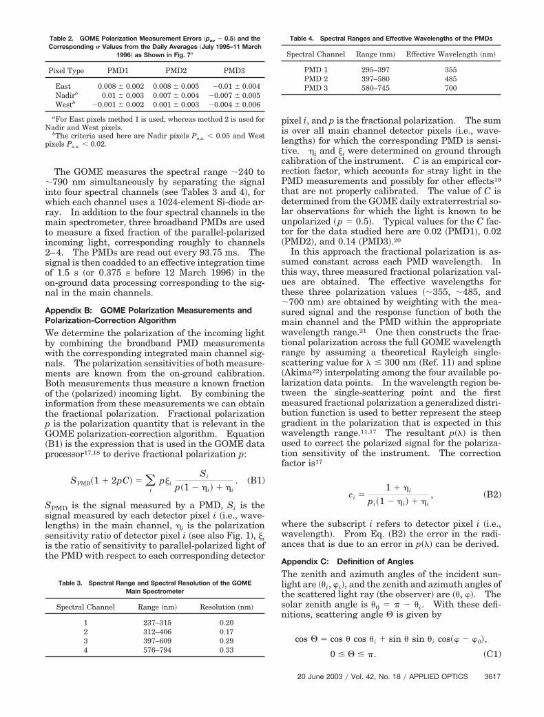
pixel i, and p is the fractional polarization. The sumis over all main channel detector pixels �i.e., wave-lengths� for which the corresponding PMD is sensi-tive. �i and �i were determined on ground throughcalibration of the instrument. C is an empirical cor-rection factor, which accounts for stray light in thePMD measurements and possibly for other effects19
that are not properly calibrated. The value of C isdetermined from the GOME daily extraterrestrial so-lar observations for which the light is known to beunpolarized �p � 0.5�. Typical values for the C fac-tor for the data studied here are 0.02 �PMD1�, 0.02�PMD2�, and 0.14 �PMD3�.20
In this approach the fractional polarization is as-sumed constant across each PMD wavelength. Inthis way, three measured fractional polarization val-ues are obtained. The effective wavelengths forthese three polarization values ��355, �485, and�700 nm� are obtained by weighting with the mea-sured signal and the response function of both themain channel and the PMD within the appropriatewavelength range.21 One then constructs the frac-tional polarization across the full GOME wavelengthrange by assuming a theoretical Rayleigh single-scattering value for � � 300 nm �Ref. 11� and spline�Akima22� interpolating among the four available po-larization data points. In the wavelength region be-tween the single-scattering point and the firstmeasured fractional polarization a generalized distri-bution function is used to better represent the steepgradient in the polarization that is expected in thiswavelength range.11,17 The resultant p��� is thenused to correct the polarized signal for the polariza-tion sensitivity of the instrument. The correctionfactor is17
ci �1 � �i
pi�1 � �i� � �i, (B2)
where the subscript i refers to detector pixel i �i.e.,wavelength�. From Eq. �B2� the error in the radi-ances that is due to an error in p��� can be derived.
Appendix C: Definition of Angles
The zenith and azimuth angles of the incident sun-light are ��i, i�, and the zenith and azimuth angles ofthe scattered light ray �the observer� are ��, �. Thesolar zenith angle is �0 � � � �i. With these defi-nitions, scattering angle � is given by
cos � � cos � cos �i � sin � sin �i cos� � 0�,
0 � � � �. (C1)
Table 2. GOME Polarization Measurement Errors �pav � 0.5� and theCorresponding � Values from the Daily Averages �July 1995–11 March
1996� as Shown in Fig. 7a
Pixel Type PMD1 PMD2 PMD3
East 0.008 � 0.002 0.008 � 0.005 �0.01 � 0.004Nadirb 0.01 � 0.003 0.007 � 0.004 �0.007 � 0.005Westb �0.001 � 0.002 0.001 � 0.003 �0.004 � 0.006
aFor East pixels method 1 is used; whereas method 2 is used forNadir and West pixels.
bThe criteria used here are Nadir pixels Ps.s. � 0.05 and Westpixels Ps.s. � 0.02.
Table 3. Spectral Range and Spectral Resolution of the GOMEMain Spectrometer
Spectral Channel Range �nm� Resolution �nm�
1 237–315 0.202 312–406 0.173 397–609 0.294 576–794 0.33
Table 4. Spectral Ranges and Effective Wavelengths of the PMDs
Spectral Channel Range �nm� Effective Wavelength �nm�
PMD 1 295–397 355PMD 2 397–580 485PMD 3 580–745 700
20 June 2003 � Vol. 42, No. 18 � APPLIED OPTICS 3617

In Fig. 8 the local zenith and the incident andscattered light rays define three points on the unitcircle. Applying the sine rule to this spherical tri-angle �thicker curves in the figure� yields
sin���2 � ��
sin �i�
sin� � i�
sin �. (C2)
Therefore polarization angle �, i.e., the angle betweenthe polarization plane and the local meridian plane,is given by
cos � �sin �i sin� � i�
sin �. (C3)
A unique definition of � illustrated in Fig. 8 is thatit is the angle from the meridian plane to the polar-ization plane, counterclockwise as viewed by the ob-server. With this definition, 0 � � � �.Substituting the scattering angle �Eq. �C1� into Eq.�C3� and using the definition of �, one obtains
t � tan � �cos � sin �i cos� � i� � cos �i sin �
sin �i sin� � i�
�ND
, (C4)
by which
QI
� P cos 2� � PD2 � N 2
D2 � N 2 � P1 � t2
1 � t2 , (C5)
UI
� P sin 2� � P2DN
D2 � N 2 � P2t
1 � t2 . (C6)
Note that Q�I of Eq. �C5� now satisfies the choice of �by Hansen and Travis,7 as Q has the same sign as cos2�.
We thank S. Slijkhuis �now at the Deutschen Zen-trum fur Luft- und Raumfahrt �DLR�, Oberpfaffen-hofen, Germany for suggesting the underlying ideafor the polarization method presented here. Discus-sions with M. R. Dobber �now at the Royal Nether-lands Meteorological Institute�, and support from B.Aberle �DLR� are gratefully acknowledged. Thestudy presented here was performed in the frame-work of GOME validation project NL-109. Finan-cial support from the European Space Agency �ESA;GOME-2 study� and the Space Research Organisa-tion Netherlands Gebruikers Ondersteuning throughgrant EO-029 is acknowledged. We thank the ESAfor providing copyrighted GOME data �ESA © 1995–1996� processed by Zentrum fur Luft-und Raumfahrte.V.
References1. J. P. Burrows, M. Weber, M. Buchwitz, V. Rozanov, A.
Ladstatter-Weissenmayer, A. Richter, R. de Beek, R. Hoogen,K. Bramstedt, and K.-U. Eichmann, “The Global Ozone Mon-itoring Experiment �GOME�: mission concept and first scien-tific results,” J. Atmos. Sci. 56, 151–175 �1999�.
2. M. I. Mischenko and L. D. Travis, “Satellite retrieval of aerosolproperties over the ocean using polarization as well as inten-sity of reflected sunlight,” J. Geophys. Res. 102, 16989–17013�1997�.
3. M. Herman, J. L. Deuze, C. Devaux, P. Goloub, F. M. Breon,and D. Tanre, “Remote sensing of aerosols over land surfacesincluding polarization measurements and application toPOLDER measurements,” J. Geophys. Res. 102, 17039–17049�1997�.
4. D. Stam, J. F. de Haan, J. W. Hovenier, and P. Stammes,“Degree of linear polarization of light emerging from the cloud-less atmosphere in the oxygen A band,” J. Geophys. Res. 104,16843–16858 �1999�.
5. J. Chowdhary, B. Cairns, M. Mischenko, and L. Travis, “Re-trieval of aerosol properties over the ocean using multispectraland multiangle photopolarimetric measurements from the Re-search Scanning Polarimeter,” Geophys. Res. Lett. 28, 243–246 �2001�.
6. O. Hasekamp and J. Landgraf, “Tropospheric ozone informa-tion from satellite based polarization measurements,” J. Geo-phys. Res. 107, 10.1029/2001JD001346 �2002�.
7. European Space Agency, GOME Users Manual �EuropeanSpace Agency, Munich, 1995�, document SP-1182.
8. J. E. Hansen and L. D. Travis, “Light scattering in planetaryatmospheres,” Space Sci. Rev. 16, 527–610 �1974�.
9. K. L. Coulson, Polarisation and Intensity of Light in the Atmo-sphere �Deepak, Hampton, Va., 1988�.
10. I. Aben, F. Helderman, D. M. Stam, and P. Stammes, “Spectralfine-structure in the polarization skylight,” Geophys. Res.Lett. 26, 591–594 �1999�.
11. N. A. J. Schutgens and P. Stammes, “Parametrisation ofEarth’s polarization spectrum in the ultraviolet,” J. Quant.Spectros. Radiat. Transfer 75, 239–255 �2002�.
12. J. F. de Haan, P. B. Bosma, and J. W. Hovenier, “The addingmethod for multiple scattering calculations of polarized light,”Astron. Astrophys. 183, 371–391 �1987�.
13. P. Stammes, “The seventh point polarisation algorithm,” In-ternal Rep. �Royal Netherlands Meteorological Institute, DeBilt, The Netherlands, 1994�.
Fig. 8. Geometry of scattering by an atmospheric volume ele-ment. The volume element is located in the origin.
3618 APPLIED OPTICS � Vol. 42, No. 18 � 20 June 2003
14. I. Aben, M. R. Dobber, D. M. Stam, and P. Stammes, “Erroranalysis of polarisation measurements by GOME,” in GOMEGeophysical Validation Campaign �European Space Agency,Munich, 1996�, document WPP-108, pp. 51–59.
15. D. E. Bowker, R. E. Davis, D. L. Myrick, K. Stacy, and W. T.Jones, “Spectral reflectances of natural targets for use in re-mote sensing studies,” Rep. RP-1139 �NASA Langley ResearchCenter, Hampton, Va., 1985�.
16. A. Deepak and H. E. Gerber, eds., Report of the Experts Meet-ing on Aerosols and their Climatic Effects �World Meteorolog-ical Organization, Geneva, 1983�, document WCP-55.
17. Deutsches Zentrum fur Luft- und Raumfahrt, “GOME level 01 algorithms description,” Rev. 4A, Rep. ER-TN-DLR-GO-0022�Deutsches Zentrum fur Luft- und Raumfahrt, Oberpfaffen-hofen, Germany, 1996�.
18. Deutsches Zentrum fur Luft- und Raumfahrt, “GOME DataProcessor update report for GDP 0-to-1 version 2.0 and GDP
1-to-2 version 2.7,” Rev. 1A, Rep. ER-TN-DLR-GO-0043 �Deut-sches Zentrum fur Luft- und Raumfahrt, Oberpfaffenhofen,Germany, 1999�.
19. C. P. Tanzi, I. Aben, S. Slijkhuis, and E. Hegels, “Influence ofGOME in-flight degradation on Earth radiance measure-ments,” in Atmospheric Measurements from Space �EuropeanSpace Agency, 1999�, document WPP-161, Vol. 2, pp. 681–685.
20. D. Loyola, Deutsches Zentrum fur Luft- und Raumfahrt e. V.,Oberpfaffenhofen, Germany �personal communication, 2001�.
21. N. A. J. Schutgens and P. Stammes, “Improving the polarisa-tion correction algorithm of GOME �Global Ozone MonitoringExperiment,” in Polarization, Measurement, Analysis and Re-mote Sensing II, D. H. Goldstein and D. B. Chenault, eds.,Proc. SPIE 3754, 411–422 �1999�.
22. H. Akima, “A new method of interpolation and smooth curvefitting based on local procedures,” J. Assoc. Comput. Mach. 17,589–602 �1970�.
20 June 2003 � Vol. 42, No. 18 � APPLIED OPTICS 3619