
Validation of Reliable Communication in Challenged Environment
87
Validation of Reliable Communication in Challenged Enviroments Muhammad Usman Minhas Master of Science Thesis Stockholm, Sweden 2009 TRITA-ICT-EX-2009:113
Transcript of Validation of Reliable Communication in Challenged Environment

Validation of Reliable Communication in Challenged Enviroments
Muhammad Usman Minhas
Master of Science Thesis Stockholm, Sweden 2009
TRITA-ICT-EX-2009:113

KTH ROYAL INSTITUTE OF TECHNOLOGY
Validation of Reliable Communication in
Challenged Environment
by
Muhammad Usman Minhas
A thesis submitted in partial fulfillment for the
degree of MS Internetworking
in the
Telecommunications System Laboratory
Department of Microelectronics and Information Technology
October 2009

Declaration of Authorship
I, Muhammad Usman Minhas, declare that this thesis titled, ’Visualization of Reliable
Communication in Challenged Environment’ and the work presented in it are my own.
I confirm that:
� This work was done wholly or mainly while in candidature for a masters degree at
this University.
� Where any part of this thesis has previously been submitted for a degree or any
other qualification at this University or any other institution, this has been clearly
stated.
� Where I have consulted the published work of others, this is always clearly at-
tributed.
� Where I have quoted from the work of others, the source is always given. With
the exception of such quotations, this thesis is entirely my own work.
� I have acknowledged all main sources of help.
� Where the thesis is based on work done by myself jointly with others, I have made
clear exactly what was done by others and what I have contributed myself.
Signed:
Date:
i
KTH ROYAL INSTITUTE OF TECHNOLOGY
Abstract
Telecommunications System Laboratory
Department of Microelectronics and Information Technology
MS Internetworking
by Muhammad Usman Minhas
Providing reliable routing in MANET is ever challenging. Protocols have to trade off be-
tween routing accuracy and update frequency. Mobile devices have resource limitations
in terms of battery power, processing, and storage. Efficient utilization these resources
is one of the key challenges. Routing protocol have to balance between update frequency
and routing accuracy.
This thesis work presents reliable routing in mobile ad hoc networks. As a part of thesis
work Neighborhood Fisheye State Routing (NFSR) protocol is implemented as a proof-
of-concept. Neighborhood concept is improved which uses reliable metric for calculating
path stabilities and finds reliable path to destination. Link emulation for emulating
wireless link instabilities in terms of packet loss is implemented. Finally, self-healing
and self-optimization for NFSR is validated. Topology and forwarding table computing
time is evaluated in different sets of basic topologies.
KTH ROYAL INSTITUTE OF TECHNOLOGY
Abstract
Telecommunications System Laboratory
Department of Microelectronics and Information Technology
MS Internetworking
by Muhammad Usman Minhas
Tillhandahlla tillfrlitlig routing i MANET r alltid en utmaning. Protokollen mste avvgas
mellan routingnoggrannheten och uppdateringsfrekvensen. Mobilapparater bestr av
resurser som r begrnsade som exempelvis batterier, processorkapacitet och lagring. Ef-
fektivt utnyttjande av dessa resurser r en av de viktigaste utmaningar. Routingspro-
tokollen mste anpassas s att man nr bst resultat mellan uppdateringsfrekvensen och
noggranhet fr routing.
Detta examensarbete presenterar en tillfrlitlig routing i mobila ad hoc-ntverk. Som
en del av examensarbetet har vi implementerat protokollet: Neighborhood Fisheye
State Routing (NFSR) som ett proof-of-concept. Neighborhood konceptet har frbt-
trats, genom att anvnda tillfrlitliga mtt fr att berkna banans stabilitet och hitta plitlig
bana till destinationen. Lnkemulering fr att efterlikna trdlslnkinstabilitet fr paketfrlust
r genomfrd. Slutligen sjlvlkande och sjlvoptimering fr NFSR har vi validerat. Topologi
och vidarebefordran av datoranvndningenstidstabell bedms i olika grundlggande uppst-
tningar av topologier.

Acknowledgements
This thesis work has been carried out in NEC Europe Research Laboratories, Network
Division, Heidelberg, Germany.
First and foremost, I would like to thank to Dr. Markus Hidell and Dr. Marcus Scholler
for giving valuable insight to accomplish my task. I would like to express my gratitude to
Dr. Stefan Schmid for his support and technical guidance, which determines the success
of this work.
Next big thanks to all my friends in Germany and Sweden who supported me during
my thesis work with special thanks to Mudassar Majeed, Muzamil Aziz Chaudhry, and
Khurram Shahzad who spent their precious time for making it a valuable document.
Finally, I am indebted my deepest thanks to my family for their love, support, and
prayers during my studies far away from them.
iv

Contents
Declaration of Authorship i
Abstract ii
Abstract in Swedish iii
Acknowledgements iv
List of Figures viii
List of Tables ix
Abbreviations x
1 Introduction 11.1 Background . . . . . . . . . . . . . . . . . . . . . . . . . . . . . . . . . . 11.2 Problem Definition . . . . . . . . . . . . . . . . . . . . . . . . . . . . . . 31.3 Purpose . . . . . . . . . . . . . . . . . . . . . . . . . . . . . . . . . . . . . 41.4 Goal of Thesis . . . . . . . . . . . . . . . . . . . . . . . . . . . . . . . . . 51.5 Methodology . . . . . . . . . . . . . . . . . . . . . . . . . . . . . . . . . . 51.6 Outline . . . . . . . . . . . . . . . . . . . . . . . . . . . . . . . . . . . . . 61.7 Summary . . . . . . . . . . . . . . . . . . . . . . . . . . . . . . . . . . . . 7
2 Literature Review 82.1 Communication Networks . . . . . . . . . . . . . . . . . . . . . . . . . . . 8
2.1.1 Wireless Networks . . . . . . . . . . . . . . . . . . . . . . . . . . . 92.1.2 Infrastructure versus Ad hoc Networks . . . . . . . . . . . . . . . . 10
2.2 Mobile Ad hoc Networks (MANET) . . . . . . . . . . . . . . . . . . . . . 102.2.1 Applications of MANET . . . . . . . . . . . . . . . . . . . . . . . . 112.2.2 Routing Issues in MANET . . . . . . . . . . . . . . . . . . . . . . 112.2.3 Research work done in MANETs . . . . . . . . . . . . . . . . . . . 12
2.3 Autonomic Computing . . . . . . . . . . . . . . . . . . . . . . . . . . . . 122.3.1 Functional Areas (Self properties) . . . . . . . . . . . . . . . . . . 13
2.4 Autonomous Network Architecture (ANA) . . . . . . . . . . . . . . . . . 14
v
Contents vi
2.4.1 Project Objectives . . . . . . . . . . . . . . . . . . . . . . . . . . . 152.5 ANA Core Software . . . . . . . . . . . . . . . . . . . . . . . . . . . . . . 16
2.5.1 MINMEX . . . . . . . . . . . . . . . . . . . . . . . . . . . . . . . . 162.5.2 Playground . . . . . . . . . . . . . . . . . . . . . . . . . . . . . . . 172.5.3 ANA Brick . . . . . . . . . . . . . . . . . . . . . . . . . . . . . . . 17
2.6 Summary . . . . . . . . . . . . . . . . . . . . . . . . . . . . . . . . . . . . 19
3 Protocol Design 203.1 Fisheye State Routing (FSR) Protocol . . . . . . . . . . . . . . . . . . . . 20
3.1.1 Protocol model . . . . . . . . . . . . . . . . . . . . . . . . . . . . . 213.1.2 FSR Functionality . . . . . . . . . . . . . . . . . . . . . . . . . . . 213.1.3 Problems with FSR . . . . . . . . . . . . . . . . . . . . . . . . . . 21
3.2 Neighborhood Fisheye State Routing (NFSR) Protocol . . . . . . . . . . . 223.2.1 Protocol Enhancements . . . . . . . . . . . . . . . . . . . . . . . . 23
3.2.1.1 Link Reliability . . . . . . . . . . . . . . . . . . . . . . . 233.2.1.2 Calculating Path Reliability . . . . . . . . . . . . . . . . 233.2.1.3 Neighborhood . . . . . . . . . . . . . . . . . . . . . . . . 24
3.2.2 Protocol Design . . . . . . . . . . . . . . . . . . . . . . . . . . . . . 253.3 Link Emulation (DROP) . . . . . . . . . . . . . . . . . . . . . . . . . . . . 27
3.3.1 Placement in Node Stack . . . . . . . . . . . . . . . . . . . . . . . 283.4 Summary . . . . . . . . . . . . . . . . . . . . . . . . . . . . . . . . . . . . 28
4 NFSR Implementation 304.1 ANA Core Abstractions . . . . . . . . . . . . . . . . . . . . . . . . . . . . 30
4.1.1 Basic Abstractions . . . . . . . . . . . . . . . . . . . . . . . . . . . 304.1.2 Compartment and Information Channels . . . . . . . . . . . . . . 314.1.3 Communication Paradigms . . . . . . . . . . . . . . . . . . . . . . 33
4.2 Compartment API . . . . . . . . . . . . . . . . . . . . . . . . . . . . . . . 344.2.1 Basic Primitives . . . . . . . . . . . . . . . . . . . . . . . . . . . . 354.2.2 Context and service arguments . . . . . . . . . . . . . . . . . . . . 384.2.3 Recommended structure for a brick . . . . . . . . . . . . . . . . . 394.2.4 Further details and operations . . . . . . . . . . . . . . . . . . . . 40
4.3 NFSR implementation . . . . . . . . . . . . . . . . . . . . . . . . . . . . . 404.3.1 Node Architecture (Protocol stack) . . . . . . . . . . . . . . . . . 404.3.2 Initial Setup . . . . . . . . . . . . . . . . . . . . . . . . . . . . . . 414.3.3 Implementation of Neighbor Table . . . . . . . . . . . . . . . . . . 454.3.4 Implementation of Topology Table . . . . . . . . . . . . . . . . . . 464.3.5 Implementation of Forwarding Table . . . . . . . . . . . . . . . . 504.3.6 Implementation of Packet Forwarding . . . . . . . . . . . . . . . . 524.3.7 Implementation of Monitoring Part (Link stability) . . . . . . . . . 54
4.4 Summary . . . . . . . . . . . . . . . . . . . . . . . . . . . . . . . . . . . . 55
5 Experimentation and Evaluation 565.1 Performance Evaluation Criteria . . . . . . . . . . . . . . . . . . . . . . . 565.2 Experimentation and Evaluation . . . . . . . . . . . . . . . . . . . . . . . 57
5.2.1 Functional Testing . . . . . . . . . . . . . . . . . . . . . . . . . . . 575.2.2 NFSR Self-optimization . . . . . . . . . . . . . . . . . . . . . . . . 58
Contents vii
5.2.3 NFSR Self-healing . . . . . . . . . . . . . . . . . . . . . . . . . . . 605.2.4 Topology and Forwarding Table Building . . . . . . . . . . . . . . 62
5.2.4.1 Node in First Place (Node1) . . . . . . . . . . . . . . . . 625.2.4.2 Node in nth place (Noden) . . . . . . . . . . . . . . . . . 65
5.2.5 Memory Footprint . . . . . . . . . . . . . . . . . . . . . . . . . . . 675.3 Optimization Techniques . . . . . . . . . . . . . . . . . . . . . . . . . . . 67
5.3.1 NFSR Optimization . . . . . . . . . . . . . . . . . . . . . . . . . . 685.4 Summary . . . . . . . . . . . . . . . . . . . . . . . . . . . . . . . . . . . . 69
6 Theses 70
7 Conclusion and Outlook 717.1 Conclusion . . . . . . . . . . . . . . . . . . . . . . . . . . . . . . . . . . . 717.2 Outlook . . . . . . . . . . . . . . . . . . . . . . . . . . . . . . . . . . . . . 71
Bibliography 73
List of Figures
1.1 Mobile ad hoc network . . . . . . . . . . . . . . . . . . . . . . . . . . . . . 3
2.1 Network Topologies . . . . . . . . . . . . . . . . . . . . . . . . . . . . . . . 92.2 ANA Node Architecture . . . . . . . . . . . . . . . . . . . . . . . . . . . . 172.3 Bricks in Plugin and Gates Modes . . . . . . . . . . . . . . . . . . . . . . 19
3.1 Functionality of a routing protocol . . . . . . . . . . . . . . . . . . . . . . 233.2 Reliability between direct neighbors . . . . . . . . . . . . . . . . . . . . . 243.3 Reliability of an indirect neighbor . . . . . . . . . . . . . . . . . . . . . . . 243.4 Neighborhood for NodeA . . . . . . . . . . . . . . . . . . . . . . . . . . . 263.5 DROP module affecting node communication . . . . . . . . . . . . . . . . 283.6 DROP module affecting individual links on a node . . . . . . . . . . . . . 29
4.1 Network Compartments . . . . . . . . . . . . . . . . . . . . . . . . . . . . 324.2 Compartment relation with OSI model . . . . . . . . . . . . . . . . . . . . 324.3 Information channels . . . . . . . . . . . . . . . . . . . . . . . . . . . . . . 334.4 Intra-compartment communication . . . . . . . . . . . . . . . . . . . . . . 334.5 Inter-compartment communication . . . . . . . . . . . . . . . . . . . . . . 344.6 Protocol stack for NFSR Brick . . . . . . . . . . . . . . . . . . . . . . . . 414.7 Neighbor Table . . . . . . . . . . . . . . . . . . . . . . . . . . . . . . . . . 464.8 Topology Table . . . . . . . . . . . . . . . . . . . . . . . . . . . . . . . . . 494.9 Routing Table . . . . . . . . . . . . . . . . . . . . . . . . . . . . . . . . . . 52
5.1 Topology used during development . . . . . . . . . . . . . . . . . . . . . . 575.2 Topology used for self-healing . . . . . . . . . . . . . . . . . . . . . . . . . 585.3 Self-optimization (1): Selecting path from Node2 . . . . . . . . . . . . . . 595.4 Self-optimization (2): selecting path form Node3 . . . . . . . . . . . . . . 595.5 Self-healing: Selecting path from Node2 . . . . . . . . . . . . . . . . . . . 615.6 Graph for self-healing . . . . . . . . . . . . . . . . . . . . . . . . . . . . . 615.7 Topology used for experiments . . . . . . . . . . . . . . . . . . . . . . . . 625.8 Graph for Topology build time (Node1) for basic topologies . . . . . . . . 645.9 Graph for forwarding table build time (Node1) for basic topologies . . . . 645.10 Graph for Topology build time (Noden) for basic topologies . . . . . . . . 665.11 Graph for forwarding table build time (Noden) for basic topologies . . . . 66
viii

List of Tables
5.1 Node 1 Topology Table Build Time* (seconds) . . . . . . . . . . . . . . . 635.2 Node 1 Forwarding Table Build Time (seconds) . . . . . . . . . . . . . . . 635.3 Noden Topology Table Build Time (seconds) . . . . . . . . . . . . . . . . 655.4 Noden Forwarding Table Build Time (seconds) . . . . . . . . . . . . . . . 65
ix

Abbreviations
MANET Mobile Adhoc NETwork
FSR Fisheye State Routing
NFSR Neighborhood Fisheye State Routing
OSI Open System Interconnection
TCP/IP Transmission Control Protocol/Internet Protocol
ANA Autonomous Network Architecture
MINMEX Minimum INfrastructure for Maximum EXtensibility
IDT Information Dispatch Table
KVR Key Value Repository
IDP Information Dispatch Point
IC Information Channel
WLAN Wireless Local Area Network
WPAN Wireless Personal Area Network
WMAN Wireless Metropolitan Area Network
DSDV Destination Sequenced Distance Vector
OLSR Optimized Link State R
TBRPF Topology Dissemination Based on Reverse Path Forwarding
AODV Adhoc On-demand Distance Vector
DSR Dynamic Source Routing
LS Link State
DUAL Diffuse Update Algorithm
x

Dedicated to my wonderful parents
xi
Chapter 1
Introduction
This thesis concerns enabling reliable routing in Mobile Ad hoc Networks. An enhanced
routing protocol is introduced based on Fisheye State Routing (FSR) protocol. The
new protocol introduces reliability metrics and ensures more reliable communication in
network while keeping the overhead to minimum.
The proposed protocol introduces neighborhood concept for efficient dissemination of
routing information in an efficient manner. A routing scheme used to calculate for-
warding table offers reliable shortest path to destination. Using reliability metrics and
the neighborhood concept makes use of resources such as bandwidth and power effi-
ciently. The algorithm design balances between routing accuracy, signaling overhead,
and complexity.
1.1 Background
Communication in today’s, wide area and local area, network is based on the Internet
protocol suite specified in [1]. Similar to Open System Interconnection (OSI) model
[2], it layers Transmission Control Protocol/Internet Protocol (TCP/IP) in order to
establish communication.
The use of mobile devices is increasing in our daily life. Laptops, mobile phones, smart
phones, and mobile terminal are available in different specifications from the market and
are becoming more common. These mobile devices contains wireless networking modules
which facilitates the user to connect to another device and exchange data/information
without using any Wide Area Network (WAN) connections, such as Internet. With this,
users can form networks and share information during meetings, conferences and so on.
These networks are known as Mobile Ad-hoc Networks (MANET). With the increase in
1
Chapter 1. Introduction 2
size and number of these networks the degree of complexity in these networks in terms
of formation, fault tolerance, and management is also increasing.
MANET use wireless links for its communication such as wireless Local Area Network
(WLAN), and bluetooth. There are many factors that affect wireless communication
such as long distance between two wireless nodes, natural factors such as thunder storm
and rain, and obstacles in the path of wireless communication link such as walls, build-
ings, and trees. Due to these factors signal attenuation occurs. Due to this attenuation
retransmission occurs which requires network bandwidth and battery power as well.
Battery is one of the key resources in mobile devices which requires careful and efficient
handling.
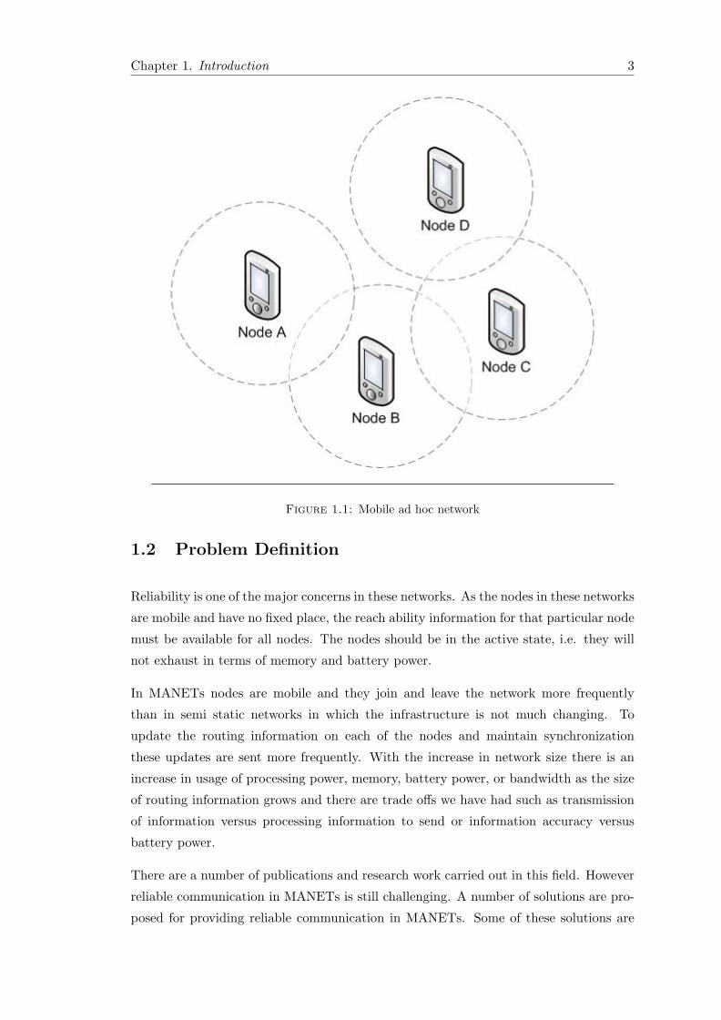
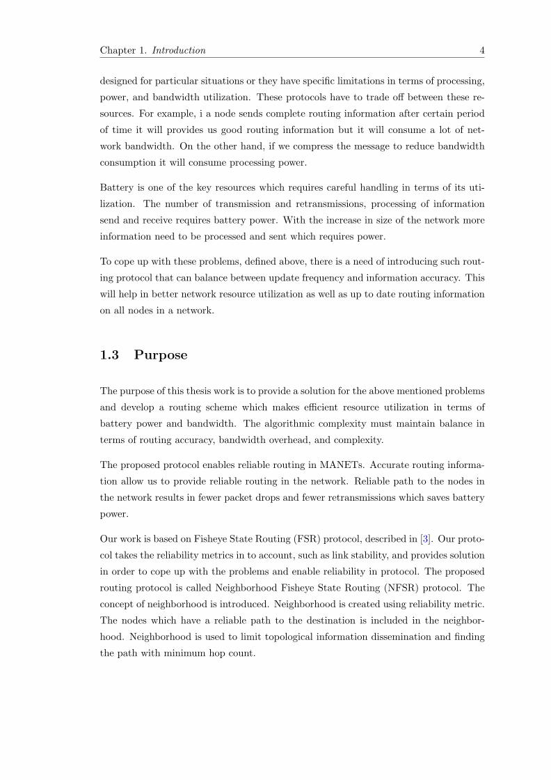
In ad hoc networks there is no dedicated device that provides facility for interconnecting
two distant nodes. In figure 1.1 below node A is not in the communication range of
node C and node D. For communication to take place between these nodes, node B and
node C have to provide routing. When the size of the network grows all nodes must
have to provide routing functionality. This clearly states that there is a need of routing
protocol in these networks. Mobile devices should provide efficient means of forwarding
information because there are resource limitations such as battery power, processing
power, and memory capacity.
Routing protocols normally emphasize on providing shortest path to the destination or
they emphasize on providing reliable path to the destination. If a path to the destination
is one hop away but the distance between these two communicating entities is very far
away which results in signal attenuation and retransmission, as described in the above
paragraph. On the other hand if a path to a destination is reliable but it consists of
multiple hops which causes communication delays.
Routing in these networks is one of the challenging issues and different works have
previously been done in this domain. As the life time of these networks is short and
network nodes participating in these networks are not stationary which means that nodes
are mobile and constantly in motion. Reliability is one of the questions arise here as
well as dissemination of this information is one of the important aspects to look at. If
the path to the destination is not reliable there will be packet retransmissions due to
packet drop which consumes memory and bandwidth.
This thesis work focuses on providing reliable routing in these networks as well as pro-
viding less overhead on resources. This thesis is based on Fisheye State Routing (FSR)
[3] protocol and enhances its functionality by introducing reliability metric for calcu-
lating routing information which results in reliable communication and efficient use of
resources.
Chapter 1. Introduction 3
Figure 1.1: Mobile ad hoc network
1.2 Problem Definition
Reliability is one of the major concerns in these networks. As the nodes in these networks
are mobile and have no fixed place, the reach ability information for that particular node
must be available for all nodes. The nodes should be in the active state, i.e. they will
not exhaust in terms of memory and battery power.
In MANETs nodes are mobile and they join and leave the network more frequently
than in semi static networks in which the infrastructure is not much changing. To
update the routing information on each of the nodes and maintain synchronization
these updates are sent more frequently. With the increase in network size there is an
increase in usage of processing power, memory, battery power, or bandwidth as the size
of routing information grows and there are trade offs we have had such as transmission
of information versus processing information to send or information accuracy versus
battery power.
There are a number of publications and research work carried out in this field. However
reliable communication in MANETs is still challenging. A number of solutions are pro-
posed for providing reliable communication in MANETs. Some of these solutions are
Chapter 1. Introduction 4
designed for particular situations or they have specific limitations in terms of processing,
power, and bandwidth utilization. These protocols have to trade off between these re-
sources. For example, i a node sends complete routing information after certain period
of time it will provides us good routing information but it will consume a lot of net-
work bandwidth. On the other hand, if we compress the message to reduce bandwidth
consumption it will consume processing power.
Battery is one of the key resources which requires careful handling in terms of its uti-
lization. The number of transmission and retransmissions, processing of information
send and receive requires battery power. With the increase in size of the network more
information need to be processed and sent which requires power.
To cope up with these problems, defined above, there is a need of introducing such rout-
ing protocol that can balance between update frequency and information accuracy. This
will help in better network resource utilization as well as up to date routing information
on all nodes in a network.
1.3 Purpose
The purpose of this thesis work is to provide a solution for the above mentioned problems
and develop a routing scheme which makes efficient resource utilization in terms of
battery power and bandwidth. The algorithmic complexity must maintain balance in
terms of routing accuracy, bandwidth overhead, and complexity.
The proposed protocol enables reliable routing in MANETs. Accurate routing informa-
tion allow us to provide reliable routing in the network. Reliable path to the nodes in
the network results in fewer packet drops and fewer retransmissions which saves battery
power.
Our work is based on Fisheye State Routing (FSR) protocol, described in [3]. Our proto-
col takes the reliability metrics in to account, such as link stability, and provides solution
in order to cope up with the problems and enable reliability in protocol. The proposed
routing protocol is called Neighborhood Fisheye State Routing (NFSR) protocol. The
concept of neighborhood is introduced. Neighborhood is created using reliability metric.
The nodes which have a reliable path to the destination is included in the neighbor-
hood. Neighborhood is used to limit topological information dissemination and finding
the path with minimum hop count.
Chapter 1. Introduction 5
1.4 Goal of Thesis
� The goal of this thesis is to enable and demonstrate the reliable routing in mo-
bile ad hoc networks and validate self-healing and self-optimization properties for
autonomic communication in challenged environment while keeping the routing
overhead small.
A routing protocol will be developed which enables reliable routing in MANETs. The
proposed routing scheme will take into account certain lower level reliability metrics
such as hop count and link stability and provides reliable communication across the
network. Devices will be capable of maintaining link reliability information and provide
reach ability on basis of reliability metric to ensure reliable path towards destination.
The proposed protocol has less overhead in terms of resources such as processor and
memory which will help us in saving system power and provides good up time to the
network node. The bandwidth requirement for the protocol is also less as it manages
the routing information in an efficient manner.
For evaluating performance, memory footprint is calculated, self-healing and self-optimization
properties are validated and results are shown. Topology and routing buildup times are
measured for basic topologies including bus, ring, and mesh. Recommendations for
optimizing protocol performance are also provided.
1.5 Methodology
To develop the protocol first we need to understand the functionality of FSR protocol.
This will setup ground for investigating and proposing the protocol. Reliability metrics
was introduced and dissemination of routing information was modeled.
The proposed protocol provides self-healing and self-optimization properties, which are
the properties for autonomic computing. To design and develop our solution it is required
to study the autonomic computing proposed by IBM in 2001 [4]. The autonomous
computing was studied in detail including its core concepts and self-* properties it
provides.
Deployment of the proposed protocol is the next part in order to test and validate pro-
tocol functionality. Implementation of the protocol was carried out on the Autonomous
Networking Architecture (ANA) [5]. ANA provides us the platform for the deploy-
ment and testing of different modules such as routing and forwarding. The autonomous
computing will be discussed later in the report.
Chapter 1. Introduction 6
ANA core software provides messaging and communication between user modules as well
as between nodes. Literature study was conducted for a good understanding on setting
up the communication between nodes and interaction between user-designed modules
(bricks) and ANA core. ANA provides different levels of programming abstractions [6]
which facilitate users for programming in ANA. Programming abstractions provided by
ANA was studied which adds an additional level of understanding for development within
ANA at different software abstraction layers. ANA Core documentation [6] provides a
good understanding on how to setup network stacks and communicate on different layers.
ANA blue print documentation [7] provides us good understanding about ANA internal
communication i.e. Publishing and un-publishing of services name resolution and look
up the services, and how to communicate with the core Software and communication
between network nodes. Functional Blocks (FB) and Information Channels (IC) are the
core components in an ANA node.
After the successful implementation and testing of routing part the implementation
moved toward the implementation of a DROP module. The testbed has Ethernet links
between the nodes. These links provides reliable communication between nodes. Due to
no availability of WLAN module in the testbed there is a need to emulate the wireless
links. DROP module is a software abstraction of the actual wireless links. The DROP
module emulates the wireless link. This module adds impurity in the link such as packet
drops. The need of this module is to demonstrate the NFSR behavior in terms of
reliability. Further the reliable communication was implemented based on the exchange
of monitoring data between two nodes.
The protocol module was extensively tested on different network topologies and is now
a part of the ANA project.
1.6 Outline
The outline of the thesis is as follows:
Chapter 2 covers literature studies about Autonomic computing, and Autonomous
Network Architecture, and core software implementation.
Chapter 3 explains about design of Neighborhood Fisheye State Routing (NFSR) pro-
tocol.
Chapter 4 details about NFSR implementation along with ANA core abstractions
which are required for the deployment of the protocol.
Chapter 1. Introduction 7
Chapter 5 details about experimentation and performance evaluation for NFSR pro-
tocol.
Chapter 6 lists Theses.
Chapter 7 concludes the work and discusses about the future work.
1.7 Summary
In this chapter brief background information is provided for this thesis. Problem with
routing protocols is explained and solution is proposed which emphasizes on enabling re-
liable routing in MANET. Methodology for implementing proposed solution is discussed
and outline for the thesis work is listed. The next chapter will list literature review which
provides in depth understanding on the background and platform for implementation.
Chapter 2
Literature Review
This chapter presents the literature review. In section 2.1 Communication networks will
be explained, section 2.2 will discuss about Mobile Ad hoc Networks (MANETs), section
2.3 will discuss autonomic computing, section 2.2.3 will discuss the research work done
in MANETs, section 2.4 will focus on Autonomous Network Architecture (ANA), which
is the development environment for protocol implementation, and ANA core software
will be discussed in section 2.5.
2.1 Communication Networks
Communication networks provide users with the facility to exchange information. A user
can be an application a network device such as network switch, a router or a computer.
These network components are called network nodes. The main motivation of building
these networks is to share information. These networks vary in sizes and functionality
they provide. Modern networks are emphasizing on building networks that can provide
multiple services such as they are able to carry voice, video and data. The motivation of
building such networks is the low cost and provides more services within same network
instead of building different network for each of the services. This brings up with many
benefits such as cost effectiveness and resource sharing.
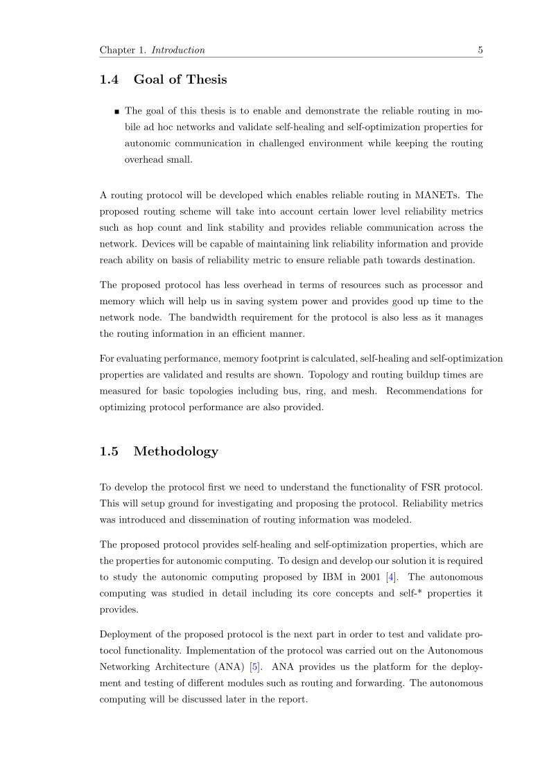
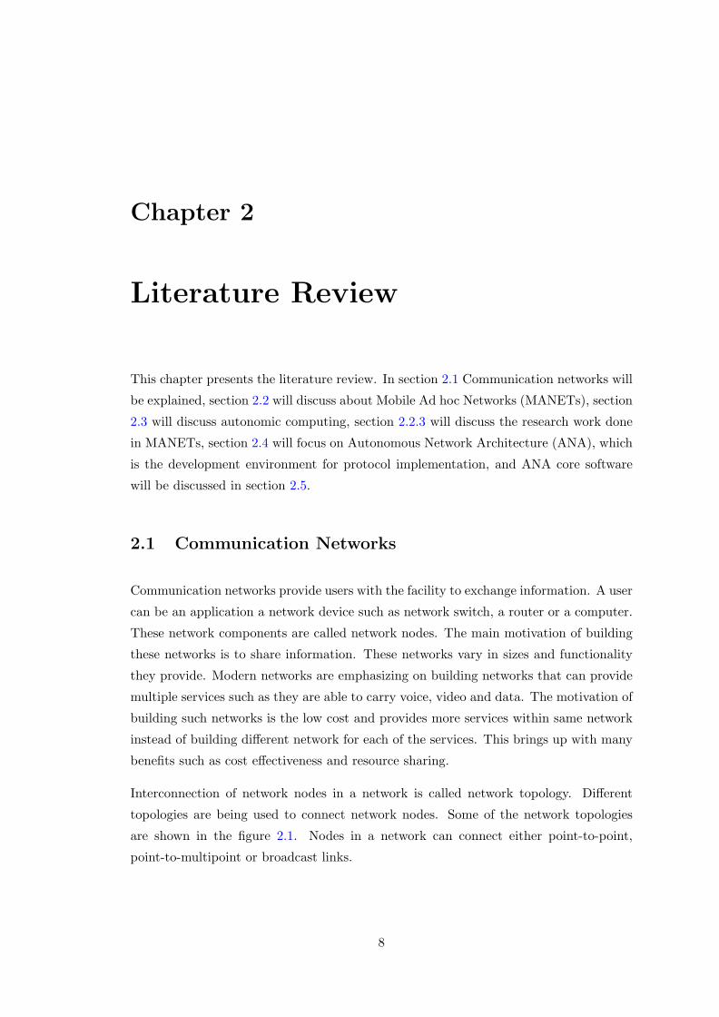
Interconnection of network nodes in a network is called network topology. Different
topologies are being used to connect network nodes. Some of the network topologies
are shown in the figure 2.1. Nodes in a network can connect either point-to-point,
point-to-multipoint or broadcast links.
8
Chapter 2. Literature Review 9
Figure 2.1: Network Topologies
2.1.1 Wireless Networks
Wireless network is a type of communication network which uses wireless medium in
order to communicate with network nodes. Devices connect using radio waves to trans-
mit the data. Devices equipped with wireless LAN cards are nowadays easily available
in the market. Devices use these mediums to connect to the network and exchange
information. Wireless networks can easily be integrated to the Ethernet technologies for
providing services to the users in the network and sharing resources. Wireless network
can be categorized into the following types:
� Wireless Personal Area Network (WPAN)
� Wireless Local Area Network (WLAN)
� Wireless Metropolitan Area Network (WMAN)
Each of these networks provide different sets of services. WPAN generally consists of
devices which are used by a single person in a particular vicinity. It includes laptop,
headset, mobile phone etc. WLAN is an alternative to LAN uses Wireless links for
transmitting and receiving data. It is generally used in building office or home networks
with small number of users. Wi-Fi is one of the standards used nowadays for WLAN.
WMAN as the name states covers fairly large terrestrial area. It connects multiple
WLAN to have inter-WLAN communication. WiMAX is one of the most commonly
used WMAN nowadays.
Chapter 2. Literature Review 10
2.1.2 Infrastructure versus Ad hoc Networks
Wireless communication can operate in two different modes as follows:
� Infrastructure mode
� Ad hoc mode
In infrastructure mode wireless devices communicate using wireless access point. There
is no direct link between the communicating devices. Access point can be connected to
the wired LAN and serves as a bridge between wireless and wired LAN. Devices can share
network resources on wired and wireless LAN. In this mode devices are pre-configured
and provides services in the network such as bridging between wireless and wired LAN.
In ad hoc mode there is no physical infrastructure required in order to communicate
between the devices. Devices discover each other, make peer-to-peer connections and
start communication. Wireless access point is not required in this network configuration.
Life of these networks are short and the setup is temporary as the devices are in motion.
With the help of this approach overall cost of network setup is lowered. Users can now
make communication possible in class rooms, as well as in conference rooms and share
information.
Mobile networks are very fast growing networks nowadays where nodes in the network
are not fixed as well as there is no need of having a physical infrastructure. MANET in
one of the types of ad hoc networks. The following section will detail about MANET.
2.2 Mobile Ad hoc Networks (MANET)
MANETs are rapidly build networks with no physical infrastructure. These networks
are deployed in response to an application need. For example some of the users wants
to share data in a conference having no Internet connectivity. Mobile devices having
radio interfaces such as wireless LAN card or bluetooth are frequently available in the
market. Due to frequent availability of these devices the number of use of these devices
also increases. On the other hand the size of these networks is also increasing and having
more and more nodes in the network.
With the increase in size and number of these networks there is a need of routing protocol
for efficient dissemination of reach ability information. The routing in MANETs is ever
challenging as these devices have resource limitations in terms of bandwidth and power.
These networks are dynamic and rapidly changing and contains multiple hops [9]. To
Chapter 2. Literature Review 11
incorporate these behaviors a routing protocol must adopt to the changing network and
efficient dissemination of routing information for a consistent network operation.
2.2.1 Applications of MANET
Some of the applications of MANETs are in military applications. They are also very
useful in natural disaster situations, when combined with satellite based information de-
livery, such as hurricane, earthquakes, and fire where there is no expected infrastructure
due to disaster or due to remote location. These networks are also very useful in indus-
trial applications and commercial applications such as data exchange between devices
[9].
Unlike the Internet, where there are established management and configurations bodies,
MANETs operate in an autonomous fashion. These networks are self-managing and
need to adopt to changes in the surrounding. For example deciding link connectivity,
if there are more than one links available. Also if there is a change in the network
connectivity graph it should be capable of adopting the changing environment.
2.2.2 Routing Issues in MANET
Routing is one of the challenging domains in MANETs due to memory and battery power
limitations. In MANETs the routing protocols are generally classified as proactive and
reactive protocols.
Proactive protocols compute the paths to the destination prior to the actual commu-
nication. This results in less network delays in communication but offers some overhead
on the processing and power of the node as it computes the routes periodically by sending
and receiving the data to the nodes in the network. Some of the examples of proactive
routing protocols are Destination-Sequenced Distance Vector Routing (DSDV) [10] pto-
tocol, Optimized Link State Routing (OLSR) [11] protocol, and Topology Dissemination
Based on Reverse Path Forwarding (TBRPF) [12].
Reactive protocols is an on demand routing protocol. It computes the route to the
destination when it is required. This behavior has good impact on memory and power
but on the other hand it introduces some delays in route computation. Some of the
examples of reactive routing protocols are Ad hoc On-demand Distance Vector (AODV)
[13] routing, and Dynamic Source Routing (DSR) [14].
These protocols are either developed by a specific scenario in mind or they have to com-
promise in terms of its resources such as memory or battery power. If security is one of

Chapter 2. Literature Review 12
the concerns then the protocol experience overhead of encryption and decryption which
again is an overhead on the processing and causes delays. The protocols must be resilient
and provides reliable communication within the network. Furthermore protocol should
be self-healing for changing network situations and it should optimize its performance
while keeping the overhead to minimum.
This thesis work focuses on providing solution to the above mentioned problems. As the
protocol should be capable of self-healing and self-optimization we need to understand
these terminologies, which lies under the umbrella of autonomic computing.
2.2.3 Research work done in MANETs
There are several projects done in MANETs exploring different areas such as security,
quality of service, and routing. Security and quality of service is out of the scope of this
thesis. These are many solutions provided in the last few years in the domain of routing in
MANETs. Some of these solutions are Destination-Sequenced Distance Vector Routing
(DSDV) protocol [10], Optimized Link State Routing (OLSR) [11] protocol, Topology
Dissemination Based on Reverse Path Forwarding (TBRPF) [12], Ad hoc On-demand
Distance Vector (AODV) [13], and Dynamic Source Routing (DSR) [14].
As described in section 2.2.2 these protocols have to trade off between systems resources
in terms of memory, power, and processing. This thesis work in chapter 3 will provide
the solution to these problems.
The next section will briefly describe the important concepts of autonomic computing.
2.3 Autonomic Computing
Another research area is focusing on the autonomous networks. The motivation behind
these networks is to provide self managed networks which requires less interaction from
the user and provides scalable solution considering current network growth and future
needs of the users. These networks will act according to the policies which are specified
by the network operators and users.
In 2001 IBM proposed a new computing model which works autonomously and regulates
itself [4]. This new model for computing was called autonomous computing. The main
motivation in providing such a solution was the lack of IT personal in the growing IT
industry containing millions of systems, with billions of users and trillion of devices.
This exponentially increasing growth rates creates a shortage of IT professionals in the
industry.
Chapter 2. Literature Review 13
The motivation is to make the computer systems in such a way that they work au-
tonomously and provides services to the users according to defined/agreed policies. The
system should also have the ability to heal itself in case of problems, and the system
should be secure so as to protect itself from the threats such as viruses [4].
Autonomic computing provides several short term and long term benefits. With Auto-
nomic computing operational costs will be reduced, simplified management for IT sys-
tems and simplified user experience due to highly responsive systems, maximum system
availability due to self-healing, maximum CPU utilization which helps in simulating
complex problems, such as medical, mathematical etc., in a distributed environment.
end-to-end service level management which ensures that minimum agreed services will
be available to the users at all times.
2.3.1 Functional Areas (Self properties)
Autonomic computing have self-* properties which an autonomic system must provide.
Following is a brief description of these properties:
Self-Configuration In large enterprises it is not convenient to configure all the network
components, this is also time consuming and requires expertise, but even with expertise
it is vulnerable to human errors.
Automatic configuration of network components means that components are able to
configure themselves according to the defined set of policies [15]. For example a network
device should be capable of configuring its interface addresses at node start time, in order
to setup the communication, that does not conflict with any device in the network. The
system should be capable of knowing its environment in which it is operating. With
self-configuration the system is capable of configuring itself according to the current
environment.
Self-Optimization In the current system there are number of parameters that are re-
quired to setup correctly for a system to have optimized performance. This requires
expertise and time well enough to study the system behavior and optimize it’s perfor-
mance.
Automatic management of network components and self optimization of network com-
ponents ensure service level management and provide minimum/agreed set of services
to the users at all times. The system is capable of managing itself by gathering statistics
(self and neighboring) and optimizes its performance for making the system responsive.
An autonomous system will continuously try to optimize its performance and make
Chapter 2. Literature Review 14
themselves efficient in terms of cost and performance. This will be achieved by learning
its own behavior and modify its parameters by itself [15].
Self-Healing In conventional networks there are facilities for monitoring the system
behavior. If there is a fault in the system then human interaction is required which is
time consuming and could take a lot of time which results in loss of services and leads
to financial loss such as problems with bank ATM network.
In autonomous systems the system is capable to monitor itself against problems and
errors. The diagnosis on the system behavior is made to find the problems and the
feasible solution. A solution could be an upgrade in software or a patch or if no solution
is available should tell the support staff or developers about it [15]. For minor problems
system should manage its resources and reconfigure itself accordingly. This will enable
the system to be up at all the times and run smoothly.
Self-Protection The system should maintain integrity and self-protection in case of
threats and outer attacks such as intrusion or cascading attacks. The system should be
capable of protecting its resources entirely. It should protect the resources by sensing
attacks that could happen in future.
Autonomic network focuses on these above specified goals providing functionality and
incorporation of new features in the future Internet. The next section will focus on the
ANA project. The project is an EU funded project and is focusing on the autonomous
network communication. ANA is following the clean slate approach and building the
network architecture from the scratch. The purpose of discussing ANA here is that the
implementation of NFSR will use ANA core software.
2.4 Autonomous Network Architecture (ANA)
The ANA project [5] is a European Union framework program six project started un-
der Situated and autonomic communications [16] and focusing on upcoming network
requirements in the upcoming years.
The ANA framework is focusing on to build the network architecture using a clean
slate approach which means building from scratch. The aim of the ANA project is to
provide a network architecture which is dynamic, autonomous and extensible. The ANA
project will provide flexible and autonomic formation of networks and network nodes.
For achieving the autonomic formation and other goals that ANA has, the software
should provide maximum flexibility and support for functional scaling.
Chapter 2. Literature Review 15
Unlike to TCP/IP implementation of todays Internet, the ANA network stack is not
fixed. The stack is dynamically built using the current needs of the network components,
which implies that whole protocol stack does not need to be implemented in order for a
node to work.
2.4.1 Project Objectives
The ANA project has two primary objectives which work in a closed loop providing
feedback to each other.
� Scientific Objectives In order to identify the basic requirements for the au-
tonomous networks providing scalability of the network not in terms of size but
also in functionality. The project setup the hypothesis which says that the network
with self-* attributes are scalable and provides richer set of services.
The scientific research will come up with a new Network Architecture. The goal
is to provide autonomic network formation for a large scale network. The network
nodes should also be formatted in an autonomic fashion. The network should pro-
vide self-association, self-reorganization, and should support mobility, and provide
multiple administrative domains.
� Technological Objectives The project will not only aim in providing theoretical
solution for autonomous networks architecture but it will also provide proof of
concept and demonstrate such networks by implementing them in real life.
In the first phase Ethernet switches will be used and will demonstrate self-organization
of a network. The network design should scale to 105 nodes. The consortium alone
will not have resources to build such a large network. To overcome this problem,
multiple nodes will run on the same physical device in their separate environments
and communicate with each other on the same machine as well as with other
machines.
In the second step the constraints will be loosen and the wireless and multi-
hop communication will be enabled. The focus in this step will be on the self-
organization of a node in a global environment.
These two goals, scientific and technological work in a closed loop and provide feed-
back to each of them. ANA uses a test-bed for implementation and investigations of
scientific work while looking at the far looking character for situated and autonomic
communication [17].
Chapter 2. Literature Review 16
2.5 ANA Core Software
This section describes ANA core software. It is necessary to understand the core software
architecture as the implementation of NFSR is based on this. The core software provides
a container to run the attached modules as well as it provides all the basic features
required such as communication between the ANA nodes.
2.5.1 MINMEX
MINMEX stands for Minimal Infrastructure for Maximum Extensibility (MINMEX). It
provides a bootstrap to run ANA. MINMEX is responsible for all of the communication
between bricks. It contains management units which allow bricks to discover other local
bricks [6]. MINMEX maintains its information in tables. Following is a brief description
of each of the MINMEX tables.
� Brick Table holds the information about all of the bricks attached to MINMEX.
This table stores the pointer to the message queues. It maintains information
about Permanent and temporary IDPs owned by each brick in order to ensure
that no brick exceeds its quota limit. Brick Table allows MINMEX to send data
and notification messages to each brick.
� Information Dispatch Table (IDT) has the information on registered Infor-
mation Dispatch Points (IDP) which are similar to network pointers and provides
communication with the bricks. At MINMEX level this table is used to map IDP
with the brick.
� Key Value Repository (KVR) is helpful in locating bricks on local node. With
the help of this table a node publish an IDP which typically maps to a particular
service. KVR contains the IDPs and set of keywords allowing to retrieve the value.
When we resolve some service with the service name given in struct service s it is
resolved by the KVR which returns the IDP to that service.
� Notification Table stores event registration for all of the bricks attached to ANA.
If a brick is registered to a particular event notification. When an event is triggered
notification table is check and message is sent to of the bricks that are registered
for that particular event.
Chapter 2. Literature Review 17
2.5.2 Playground
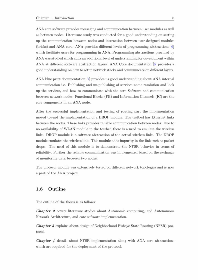
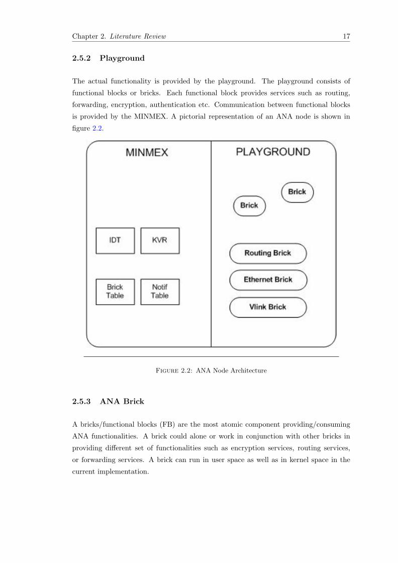
The actual functionality is provided by the playground. The playground consists of
functional blocks or bricks. Each functional block provides services such as routing,
forwarding, encryption, authentication etc. Communication between functional blocks
is provided by the MINMEX. A pictorial representation of an ANA node is shown in
figure 2.2.
Figure 2.2: ANA Node Architecture
2.5.3 ANA Brick
A bricks/functional blocks (FB) are the most atomic component providing/consuming
ANA functionalities. A brick could alone or work in conjunction with other bricks in
providing different set of functionalities such as encryption services, routing services,
or forwarding services. A brick can run in user space as well as in kernel space in the
current implementation.
Chapter 2. Literature Review 18
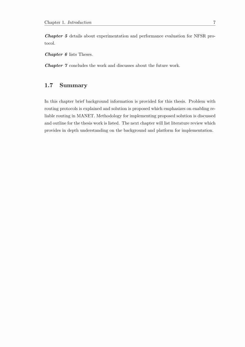
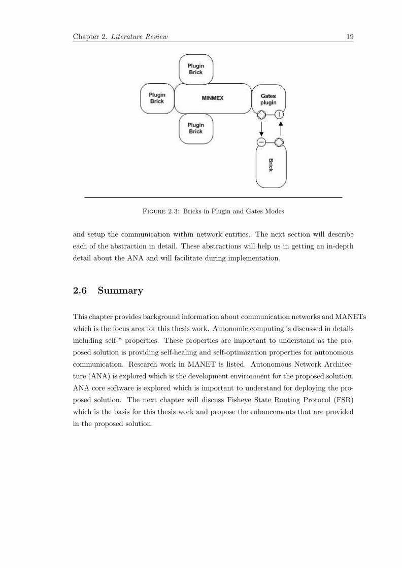
The bricks in the ANA can be attached using two different modes known as Plug-in
mode and Gates mode shown in figure 2.3. A brief explanation of these modes are
described below:
Plugin Mode
In plug-in mode a brick can directly be attached with the MINMEX and start its opera-
tion. In this mode a brick can communicate directly with the MINMEX and provides/-
consumes services on an ANA node.
User space MINMEX In this configuration the code of the brick, located in .so
files, are loaded at run time. .so files are similar to dynamic linked libraries (dll) in
windows. The brick in this case runs under MINMEX process. For each of the brick
a separate thread is maintained. Communication between the bricks is done through
direct function calls.
Kernel space MINMEX In this configuration the process is attached as a kernel
module. In this configuration MINMEX and brick should also be running as kernel
modules. Communication between the bricks is done through direct function calls.
Gates Mode
In the Gates mode the communication between brick and the MINMEX is provided by
Gates brick. The brick cannot directly communicate with the MINMEX.
User space MINMEX In this configuration the communication between MINMEX
and the user brick is done through gates plug-in. This method of attaching the brick
with the MINMEX using gates plug-in brick could be used for connecting modules from
different system architecture in order to provide/consume services.
Kernel space MINMEX The above shown module can be compiled so as to provide
services as a kernel module. The available communication gates in the kernel space are
UDP and generic network link.
A pictorial representation of plug-in and gates mode is shown in the figure 2.3.
ANA provides core abstractions which mean that these are the basic elements that are
required and supported by ANA. These abstractions are the building blocks for ANA
Chapter 2. Literature Review 19
Figure 2.3: Bricks in Plugin and Gates Modes
and setup the communication within network entities. The next section will describe
each of the abstraction in detail. These abstractions will help us in getting an in-depth
detail about the ANA and will facilitate during implementation.
2.6 Summary
This chapter provides background information about communication networks and MANETs
which is the focus area for this thesis work. Autonomic computing is discussed in details
including self-* properties. These properties are important to understand as the pro-
posed solution is providing self-healing and self-optimization properties for autonomous
communication. Research work in MANET is listed. Autonomous Network Architec-
ture (ANA) is explored which is the development environment for the proposed solution.
ANA core software is explored which is important to understand for deploying the pro-
posed solution. The next chapter will discuss Fisheye State Routing Protocol (FSR)
which is the basis for this thesis work and propose the enhancements that are provided
in the proposed solution.
Chapter 3
Protocol Design
This chapter will first discuss in section 3.1 about FSR protocol [3] briefly. In section 3.2
enhancements provided by NFSR will be discussed. Finally, section 3.3 will introduce a
DROP module which emulates wireless links and helps us in calculating link stabilities.
3.1 Fisheye State Routing (FSR) Protocol
As described in the literature review, section 2.2.2, that there are many solutions that
are provided for MANETs, but we have to trade off between network bandwidth, mem-
ory, processing etc. To minimize the overhead of routing protocol in terms of memory,
processing, and network bandwidth there was a need of such protocol that can handle
these issues in a well defined manner. FSR protocol introduces a novel idea of main-
taining and disseminating node information that produces less overhead on the protocol
itself.
The aim of FSR is to reduce the routing update overhead by introducing the concept
of fisheye. FSR uses a notion of multiple level fisheye scopes. In FSR a node maintains
detailed information about its neighbors and route detail reduces as the distance to a
destination increases which means it keeps aggregated information for the distant nodes.
With this approach the protocol overhead of sending, receiving, and processing link state
updates on a node decreases.
20
Chapter 3. Protocol Design 21
3.1.1 Protocol model
FSR uses one list and three tables for maintaining network information. There is a
neighbor list which hold the information about all of its directly connected neighbors.
The tables are named as topology table, next hop table and distance table.
Each destination has an entry in the topology table. Each entry in the topology table
has two parts Link State and Sequence abbreviated as LS and SEQ respectively. LS
contains the information for the destinations and the SEQ works as a time stamp for
this information. The greater the SEQ is, more up-to-date is the information.
3.1.2 FSR Functionality
FSR focused on reducing the routing updates overhead in MANET due to resource
limitations. It uses a notion of fisheye scopes to reduce the routing overhead. The
concept of the scopes is to exchange detailed information about all of the nodes in the
scope only, which is based on distance to destination of a particular node. The link state
(LS) updates are not flooded in the network, instead they are only exchanged with the
directly connected neighbors. The information for the nodes in the smaller scope are
exchanged more frequently, where as the information for far end nodes are exchanged less
frequently. Furthermore the updates are not event driven rather they are periodic which
saves the number of messages in ad hoc networks when there are frequent disconnections
and reconnections (joins and leaves) in the network. This significantly reduces the
number of routing updates. With the exchange of LS updates nodes construct topology
table and compute optimized routes [3].
With the low frequency of update messages the routing information for the far end nodes
is not much accurate. In large network this will cause slower convergence of routing
updates. The idea of having multiple scopes within network helps in routing a packet
much accurately. As the packet reaches near destination it will be in the neighborhood
of the destination and this area has the detailed and most up-to-date information about
the destination node.
3.1.3 Problems with FSR
FSR is a proactive routing algorithm. It sends routing update periodically containing
information for all of the destinations. This generally put more overhead on network
bandwidth as the complete information is sent in each update packet. TBRPF [12]
is the first routing protocol that uses reverse path forwarding to disseminate only the
Chapter 3. Protocol Design 22
differences in routing since the last update. The proposed routing protocol also generates
routing updates containing only the required information. This results in smaller LS
updates which reduces overall message overhead. This improvement comes at the cost
less accurate routing information only for distant nodes.
In FSR when the node neighborhood is created it does not take into account the reliabil-
ity of the links. It is not be appropriate to disseminate the routing information for the
nodes which are not reliable. The proposed protocol takes into account the reliability of
a link. When a link to a node is stable only that node is included in the neighborhood.
With this scheme the updates, which are sent more frequently, only contains the reliable
destinations which further reduces the message overhead on the network links by not
sending the information for non-reliable links.
The proposed protocol provides solutions to the above mentioned problems. The pro-
posed protocol ensures reliable communication within network as well as it reduces the
message size which lowers the bandwidth utilization. The next section will explain the
proposed protocol (NFSR) and describes the enhancements provided in the proposed
protocol.
3.2 Neighborhood Fisheye State Routing (NFSR) Proto-
col
This section will introduce the enhancements made to the Fish-eye State Routing (FSR)
protocol. The purpose of this thesis work is to understand the ANA architecture and to
deploy the protocol. Before this there was no implementation for the proposed protocol
in ANA. The work was carried out as a proof of concept for ANA architecture.
The proposed protocol is called Neighborhood Fisheye State Routing (NFSR) protocol.
NFSR takes into account the link stabilities. The exchange of information is based on
the principle of FSR, which is to exchange the information for nodes inside the scope
more frequently and aggregated information for distant nodes less frequently. LS up-
dates are only sent to the directly connected neighbors which saves network bandwidth.
The routing updates are sent periodically with only the necessary information, which
minimizes the size of the message. These collectively benefits us in saving processing,
memory, and network bandwidth. An architectural representation of routing protocol is
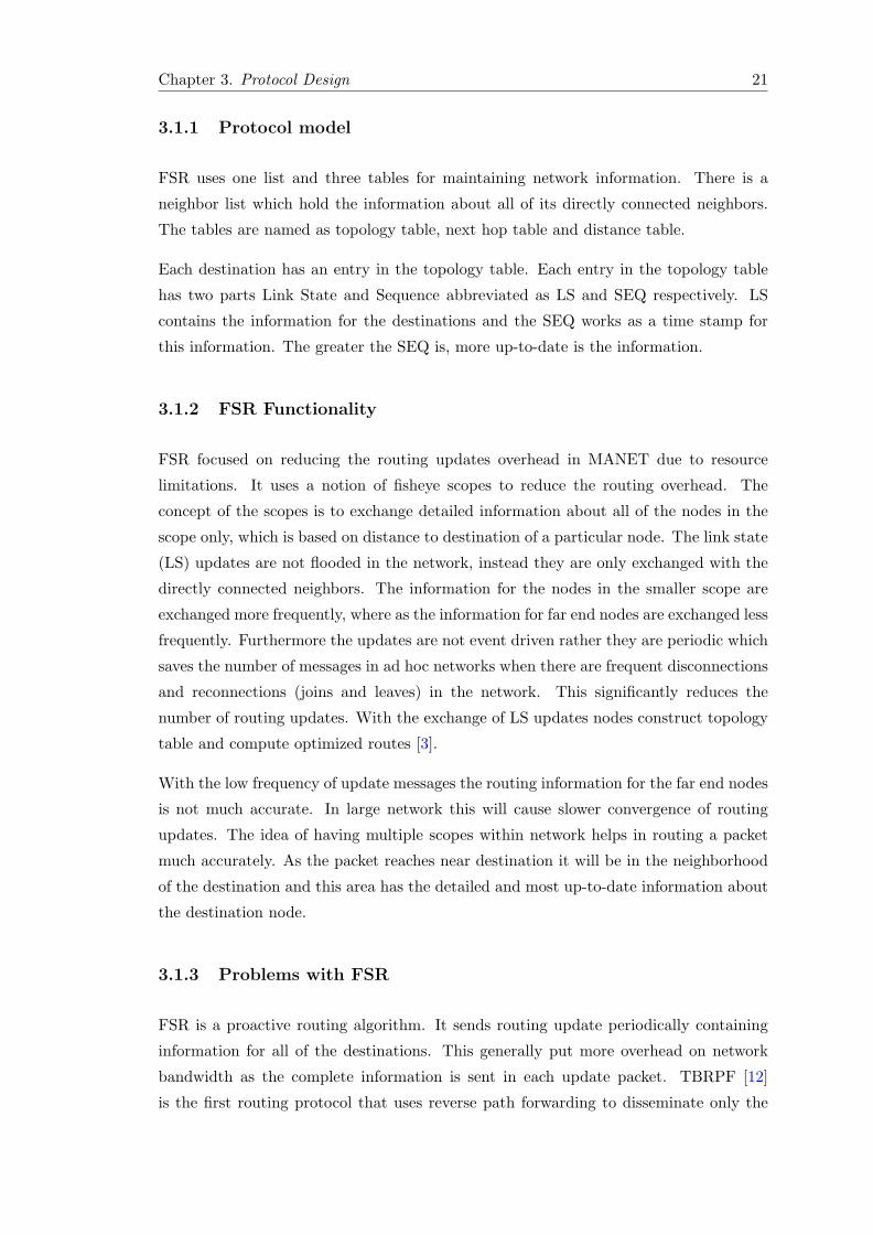
shown in the figure 3.1.
Chapter 3. Protocol Design 23
Figure 3.1: Functionality of a routing protocol
3.2.1 Protocol Enhancements
This section will describe the enhancements that are provided by the NFSR protocol. It
will discuss about the reliability metric used for the calculation of link reliability. The
process of metric calculation will also be described. Next the neighborhood creation on
the basis of link reliability will be described.
3.2.1.1 Link Reliability
Link reliability is a metric that is used for calculating the link stability. The reliability of
a link varies between 0 and 1, where 1 means that the link is 100% stable. The reliability
of a path is used to determine the reliable path to the destinations within neighborhood.
Neighborhood will be discussed in section 3.2.1.3.
3.2.1.2 Calculating Path Reliability
For the calculation of reliability monitoring data is used within the protocol. Monitoring
data contains the number of packets received by a node from its direct neighbor. A node
maintains the number of packets sent to all of its direct neighbors and upon receiving
the monitoring data it calculates the ratio between packet sent and receive and sets the
link reliability for each node. The monitoring data is exchanged periodically for each on
its neighbors in LS updates.
Chapter 3. Protocol Design 24
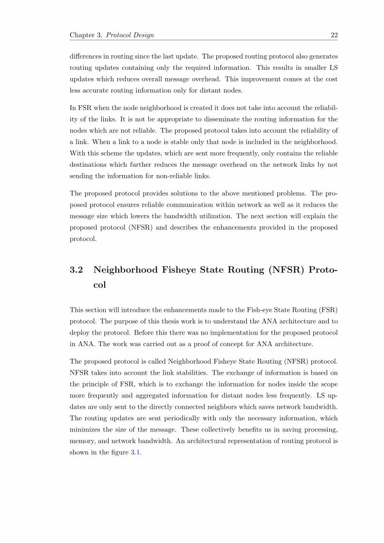
A node in a network has two types of neighbors. First direct neighbors and second
neighbors of neighbors. For directly connected neighbors the path reliability is the link
reliability between the nodes. The figure 3.2 shows the link reliability between NodeA
and NodeB.
Figure 3.2: Reliability between direct neighbors
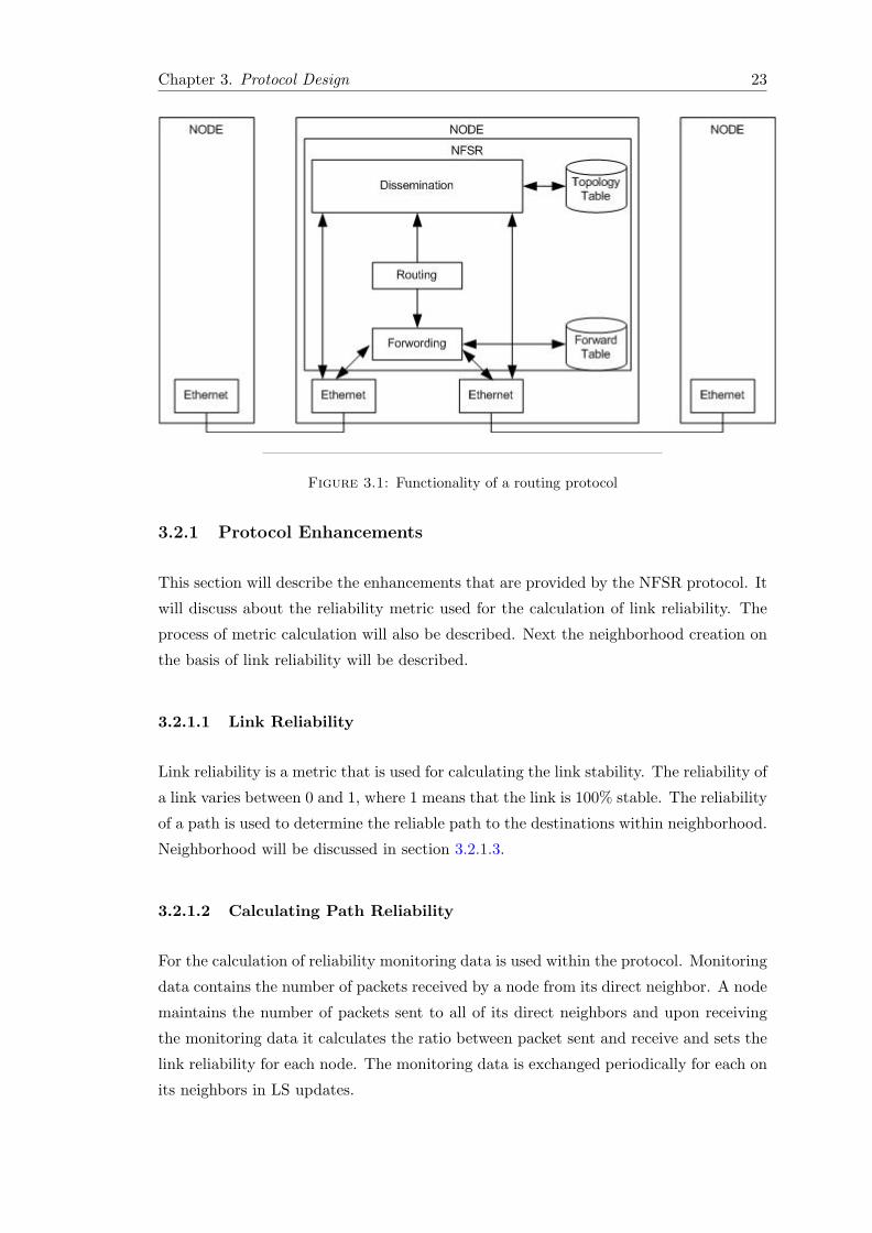
The reliability for a non-direct neighbor is the path reliability to the direct neighbor
multiplied by the path reliability that is advertised by the neighbor for the indirect
neighbor. In the figure 3.3 the path reliability between NodeA and NodeC is the link
reliability between NodeA and NodeB multiplied by link reliability for NodeC advertised
by NodeB in LS update.
Figure 3.3: Reliability of an indirect neighbor
3.2.1.3 Neighborhood
Unlike FSR, NFSR defines a neighborhood based on the used metric. The nodes in
the neighborhood are considered as reliable. NFSR maintains a balance between the
Chapter 3. Protocol Design 25
reliability and length of a path to the destination. Forwarding within the neighborhood
is based on the reliability metric and the forwarding outside the neighborhood is based on
the neighborhood. The neighborhood helps us in finding reliable path to the destination.
Neighborhood also allows us to disseminate information efficiently. Updates sent in inner
update scope contains all the nodes in the neighborhood. This update is sent more
frequently to the directly connected neighbors. This keeps directly connected neighbors
having up-to-date information, for the nodes in the neighborhood, at all the times. In
the current implementation the neighborhood is restricted to all of the nodes that are
within one hop distance.
Neighborhood calculation is based on reliability metric, as mentioned above. Path reli-
abilities are taken into account. During the initialization of the neighborhood an initial
routing table is build contain nodes in the neighborhood having reliable path to the
destination. For calculating the neighborhood, a node traverses it neighbors and if path
to this neighbor satisfies a certain stability limit then topology entry for this neighbor
is checked if it founds a topology entry for this neighbor a routing entry is created for
this neighbor and put it into the list of stable neighbors for calculating the topology
table for far end nodes using Dijkstra. If a neighbor does not satisfies the stability limit
it is put in an unstable list. For the nodes below the stability threshold, that node
is not included in the routing table and communication to that node is not possible.
The process repeats on self neighbors and all directly connected (one hop away) for the
formation of neighborhood. Path stability is calculated using the process explained in
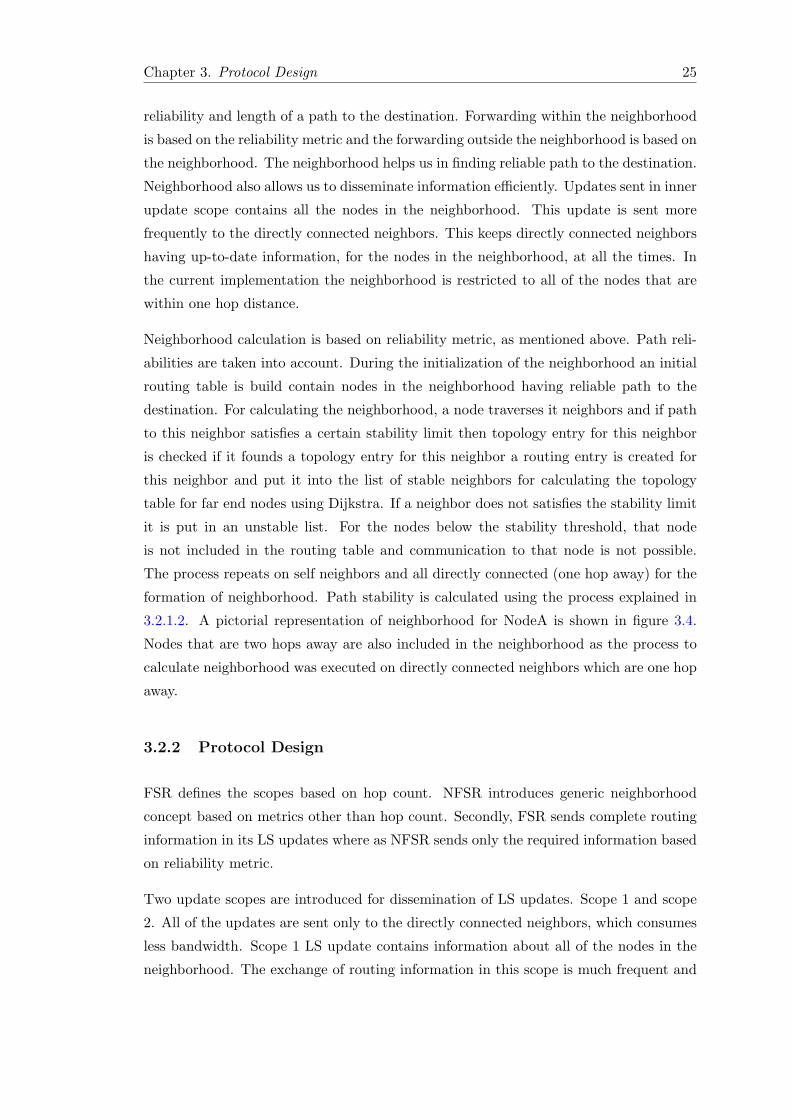
3.2.1.2. A pictorial representation of neighborhood for NodeA is shown in figure 3.4.
Nodes that are two hops away are also included in the neighborhood as the process to
calculate neighborhood was executed on directly connected neighbors which are one hop
away.
3.2.2 Protocol Design
FSR defines the scopes based on hop count. NFSR introduces generic neighborhood
concept based on metrics other than hop count. Secondly, FSR sends complete routing
information in its LS updates where as NFSR sends only the required information based
on reliability metric.
Two update scopes are introduced for dissemination of LS updates. Scope 1 and scope
2. All of the updates are sent only to the directly connected neighbors, which consumes
less bandwidth. Scope 1 LS update contains information about all of the nodes in the
neighborhood. The exchange of routing information in this scope is much frequent and
Chapter 3. Protocol Design 26
Figure 3.4: Neighborhood for NodeA
accurate as it is required to have detailed information about the nodes in the neighbor-
hood. The information for the nodes in neighborhood must be up to date, which requires
frequent message exchange. Scope 2 LS update contains all of the other nodes in the
network. Scope 2 update is sent less frequently to all the directly connected neighbors.
Scope 2 comprises of all of the nodes that are outside the neighborhood, such as distant
nodes.
NFSR aggregates relative routing information on basis of used metric depending on the
used metric for nodes beyond the neighborhood boundaries and optimize routes in a
way that the number of traversed neighbors is minimal.
Path reliability metric requires that information for topological direct neighbors are ad-
vertised in the update messages. If certain neighbor link reliability is below the minimum
threshold value then routing information for this neighbor will not be advertised. If this
link is the only link to the destination then this node will not be reachable within the
network. After the expiration of hold down time the routing entry will be deleted by the
nodes until the link stability for the node increases from the minimum threshold. This
could cause severe problem in the cases where this link is the only link between network
clusters, in this case it will cause network isolation.
Once the topology information is received through link state updates and topology
table is computed, the next step is to compute the forwarding table by applying some
routing algorithm. In the initialization step the forwarding table for the nodes in the
neighborhood is constructed. Link stabilities are taken into account . If a path to the
Chapter 3. Protocol Design 27
destination is stable that node is included in the forwarding table. If path reliability
to the destination is not stable the route for this destination is not included in the
forwarding table. After the initialization of forwarding table with all the nodes in the
neighborhood Dijkstra algorithm is applied and routes to the destination are calculated.
3.3 Link Emulation (DROP)
One of the main contribution of this thesis work is the development of DROP module
for the emulation of wireless link instabilities. ANA does not contains any Wireless LAN
brick, it uses Ethernet brick which provides more stable connection between nodes in a
network. For demonstrating the behavior of NFSR protocol there is a need to have link
instabilities between mobile nodes. The purpose of this module is to add link instabilities
to emulate wireless signal drop due to mobility of nodes in the network.
Setting Drop Percentage Nodes in MANET are mobile and have no particular
location. These nodes are constantly in motion. Due to this behavior link stability vary
in time. To emulate this behavior a drop percentage is set after a specific period of
time. A random number is selected in between upper and lower bound. These bounds
are meant to select a random value within this limit and shows a smooth movement of
a mobile device in the vicinity. Once a random number is selected within these bounds,
a cut-off percentage is calculated. The cut-off percentage lies between the value of zero
and one, where zero means no packet drop and links are stable and one means 100%
packet loss.
Dropping Packets The drop percentage is set periodically after a specific period of
time and is constantly changing. Once a cut-off value is calculated and upon receiving
a packet a random value is generated with a seed of time. If that value lies within the
calculated drop limit it is dropped. If a random value is above the calculated cut-off
limit it is passed to the upper layer.
This DROP module helps us in emulating the wireless link states. If a link is dropping
most of the received packets means mobile node is moving far away, this will cause the
packets not to reach the NFSR module for further processing, which then after a certain
amount of hold time erases the routing entries from the routing as well as from the
topology table.
Chapter 3. Protocol Design 28
3.3.1 Placement in Node Stack
The idea of creating DROP brick is to introduce link instabilities which are required in
order to show the self healing properties for NFSR protocol. Initially the DROP module
was deployed which effects the node with the same probability on each link. This means
that if a node has more than one network links on different segments, as in the case with
Node2, than for a particular span of time it will effect the communication on all of the
node links with same probability as all of the communication will pass through it. The
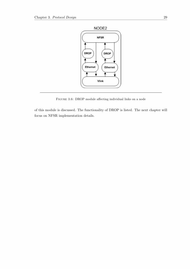
initial placement of DROP brick for Node2 is shown in the figure 3.5.
Figure 3.5: DROP module affecting node communication
With the above mentioned placement of the drop module the packet loss calculated
affects whole node communication. If a node has three neighbors then the link reliability
for all of the links will be same. Our theme is to calculate individual link reliabilities. For
this purpose we have placed the DROP module on top of individual Ethernet modules.
With this new arrangement link reliability for an individual link can be calculated which
will be purely independent of other node links. The placement of DROP brick for each
link is shown in the figure 3.6.
3.4 Summary
This chapter states FSR functionality and explains the problems in FSR. Enhancements
are provided in FSR and the proposed solution, Neighborhood Fisheye State Routing
(NFSR), is explained in detail. Link emulation module, DROP, is introduced and need
Chapter 3. Protocol Design 29
Figure 3.6: DROP module affecting individual links on a node
of this module is discussed. The functionality of DROP is listed. The next chapter will
focus on NFSR implementation details.
Chapter 4
NFSR Implementation
This chapter details the implementation of Neighborhood Fisheye State Routing (NFSR)
Protocol. Section 4.1 describes ANA core abstractions. Section 4.2 explains the com-
partment API required to publish, resolve and send messages to other bricks. Finally,
section 4.3 describes implementation details of NFSR protocol.
The NFSR protocol was deployed as a proof of concept for the ANA architecture. Pre-
viously there was no such implementation of NFSR for ANA. NFSR was deployed in
ANA using ANA standard APIs and deployed on ANA core, which is MINMEX.
4.1 ANA Core Abstractions
This section discusses ANA core abstractions. These abstrations are important to un-
derstand for development within ANA environment.
4.1.1 Basic Abstractions
Functional block
A functional block is an entity which consumes or provides resources in an ANA node.
A functional block can be a TCP module, an IP module, and can also be a hashing
function or network monitoring module. A functional block is not restricted to being
abstractions of network protocols but it can be of a complete network stack or can be a
small entity such as an encryption function or presentation module [7].
30
Chapter 4. NFSR Implementation 31
The functional abstraction is very helpful in providing complete set of functionality. We
can abstract different modules to interact with each other in order to provide specified
functionality, such as routing and forwarding.
Information Dispatch Point
Information Dispatch Point (IDP) is an important element in ANA architecture and
around it many core architecture machinery is designed. In ANA architecture each
functional block is accessed by an IDP. The binding between an IDP and an FB is
dynamic and can change over time. The binding between IDP and FB is stored in core
forwarding table. When binding is done between an FB and IDP a label is assigned to
IDP. Each IDP is then identified by that label inside an ANA node.
IDP provides generic communication method between FBs in an ANA node and provides
flexibility for re-organizing communication paths. The next hop entity, local or remote,
is always identified by a label. A single FB could have multiple IDPs attached to it. For
example one IDP for sending data and the other one is to receive the data. A single FB
could be bound to a same function but with different state.
4.1.2 Compartment and Information Channels
Compartment
ANA introduces a core concept of compartment in terms of communication paradigms.
A similar idea was given in [18]. A compartment is a homogeneous region on a network
in some regard such as with respect addresses, look up, name resolution etc.
Support for backward compatibility is one of the key requirements for any new archi-
tecture. Compartment abstraction provides us with hiding the internal implementation
details for individual network technology. It provides a good inter-communication be-
tween legacy network technologies and new communication technologies hence providing
backward compatibility. This feature will also help us in providing communication be-
tween heterogeneous technologies [7].
A compartment can span multiple nodes or could be located on a single node (for inter-
process communication on a single node). Node local communication is possible using
general compartment primitives. Compartment sets administrative policies for a com-
munication context. Boundaries of a communication context are based on technological
and/or administrative policies. A compartment boundary can be defined by a certain
type of network technology or protocol and can also be based on some policy domains.
Chapter 4. NFSR Implementation 32
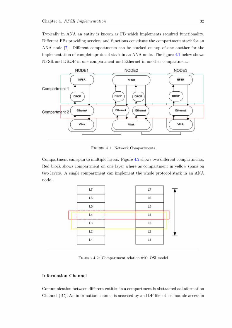
Typically in ANA an entity is known as FB which implements required functionality.
Different FBs providing services and functions constitute the compartment stack for an
ANA node [7]. Different compartments can be stacked on top of one another for the
implementation of complete protocol stack in an ANA node. The figure 4.1 below shows
NFSR and DROP in one compartment and Ethernet in another compartment.
Figure 4.1: Network Compartments
Compartment can span to multiple layers. Figure 4.2 shows two different compartments.
Red block shows compartment on one layer where as compartment in yellow spans on
two layers. A single compartment can implement the whole protocol stack in an ANA
node.
Figure 4.2: Compartment relation with OSI model
Information Channel
Communication between different entities in a compartment is abstracted as Information
Channel (IC). An information channel is accessed by an IDP like other module access in
Chapter 4. NFSR Implementation 33
ANA, while IC IDP should be bound to some entity belongs to network compartment.
IC provides channel for a remote entity. An end point of an IC could a network node or
a set of nodes, a routing module or some other software module providing functionality.
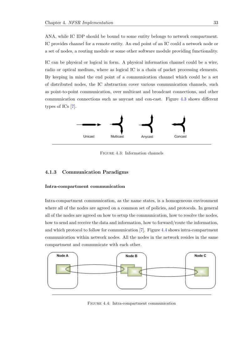
IC can be physical or logical in form. A physical information channel could be a wire,
radio or optical medium, where as logical IC is a chain of packet processing elements.
By keeping in mind the end point of a communication channel which could be a set
of distributed nodes, the IC abstraction cover various communication channels, such
as point-to-point communication, over multicast and broadcast connections, and other
communication connections such as anycast and con-cast. Figure 4.3 shows different
types of ICs [7].
Figure 4.3: Information channels
4.1.3 Communication Paradigms
Intra-compartment communication
Intra-compartment communication, as the name states, is a homogeneous environment
where all of the nodes are agreed on a common set of policies, and protocols. In general
all of the nodes are agreed on how to setup the communication, how to resolve the nodes,
how to send and receive the data and information, how to forward/route the information,
and which protocol to follow for communication [7]. Figure 4.4 shows intra-compartment
communication within network nodes. All the nodes in the network resides in the same
compartment and communicate with each other.
Figure 4.4: Intra-compartment communication
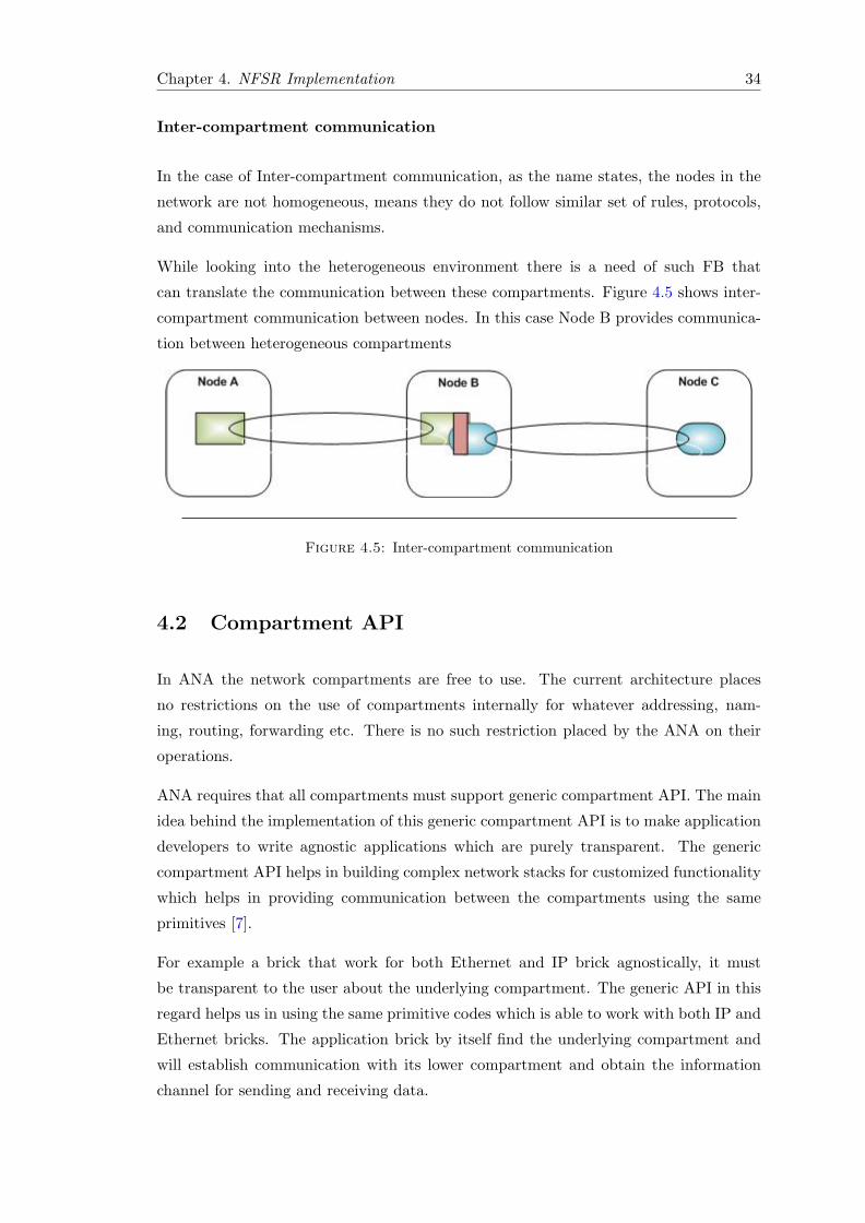
Chapter 4. NFSR Implementation 34
Inter-compartment communication
In the case of Inter-compartment communication, as the name states, the nodes in the
network are not homogeneous, means they do not follow similar set of rules, protocols,
and communication mechanisms.
While looking into the heterogeneous environment there is a need of such FB that
can translate the communication between these compartments. Figure 4.5 shows inter-
compartment communication between nodes. In this case Node B provides communica-
tion between heterogeneous compartments
Figure 4.5: Inter-compartment communication
4.2 Compartment API
In ANA the network compartments are free to use. The current architecture places
no restrictions on the use of compartments internally for whatever addressing, nam-
ing, routing, forwarding etc. There is no such restriction placed by the ANA on their
operations.
ANA requires that all compartments must support generic compartment API. The main
idea behind the implementation of this generic compartment API is to make application
developers to write agnostic applications which are purely transparent. The generic
compartment API helps in building complex network stacks for customized functionality
which helps in providing communication between the compartments using the same
primitives [7].
For example a brick that work for both Ethernet and IP brick agnostically, it must
be transparent to the user about the underlying compartment. The generic API in this
regard helps us in using the same primitive codes which is able to work with both IP and
Ethernet bricks. The application brick by itself find the underlying compartment and
will establish communication with its lower compartment and obtain the information
channel for sending and receiving data.
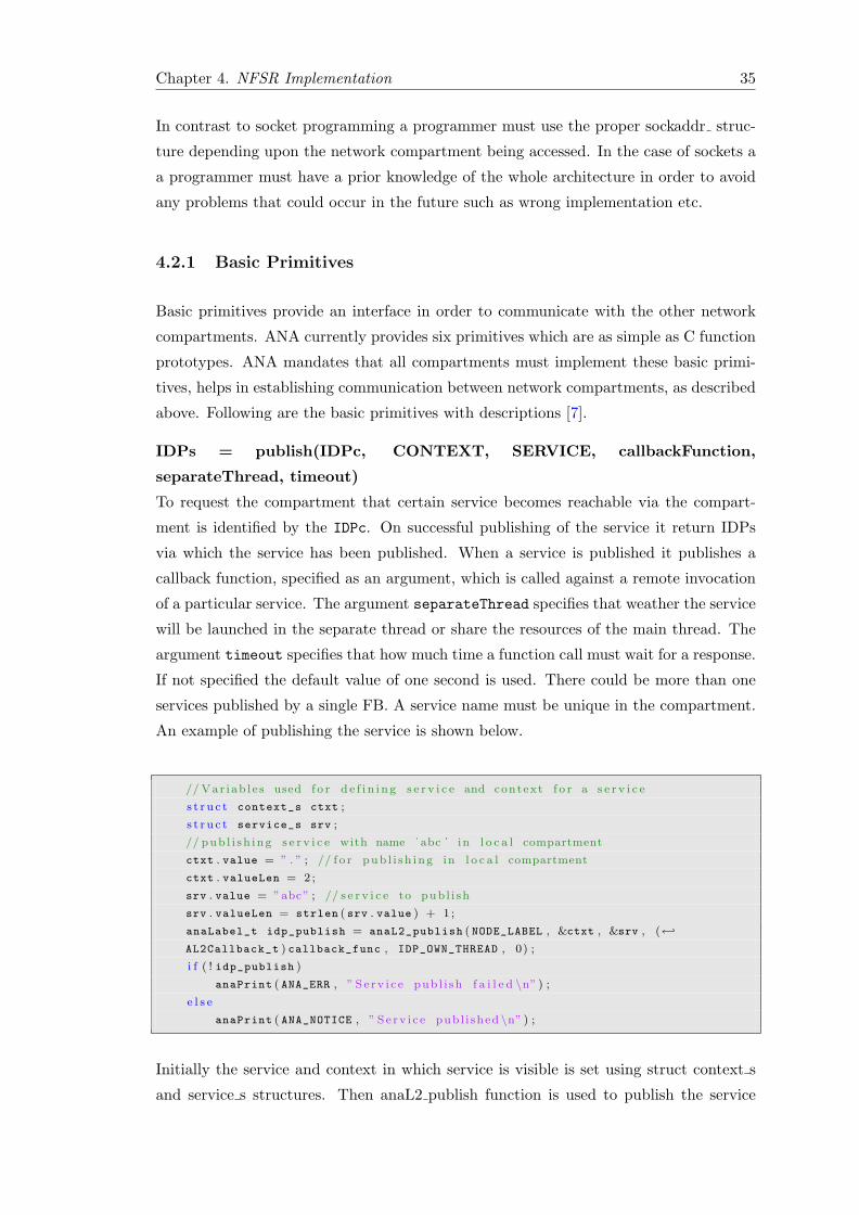
Chapter 4. NFSR Implementation 35
In contrast to socket programming a programmer must use the proper sockaddr struc-
ture depending upon the network compartment being accessed. In the case of sockets a
a programmer must have a prior knowledge of the whole architecture in order to avoid
any problems that could occur in the future such as wrong implementation etc.
4.2.1 Basic Primitives
Basic primitives provide an interface in order to communicate with the other network
compartments. ANA currently provides six primitives which are as simple as C function
prototypes. ANA mandates that all compartments must implement these basic primi-
tives, helps in establishing communication between network compartments, as described
above. Following are the basic primitives with descriptions [7].
IDPs = publish(IDPc, CONTEXT, SERVICE, callbackFunction,
separateThread, timeout)
To request the compartment that certain service becomes reachable via the compart-
ment is identified by the IDPc. On successful publishing of the service it return IDPs
via which the service has been published. When a service is published it publishes a
callback function, specified as an argument, which is called against a remote invocation
of a particular service. The argument separateThread specifies that weather the service
will be launched in the separate thread or share the resources of the main thread. The
argument timeout specifies that how much time a function call must wait for a response.
If not specified the default value of one second is used. There could be more than one
services published by a single FB. A service name must be unique in the compartment.
An example of publishing the service is shown below.
// Var iab l e s used f o r d e f i n i n g s e r v i c e and context f o r a s e r v i c e
s t r u c t context_s ctxt ;
s t r u c t service_s srv ;
// pub l i sh ing s e r v i c e with name ' abc ' in l o c a l compartment
ctxt . value = ” . ” ; // f o r pub l i sh ing in l o c a l compartment
ctxt . valueLen = 2 ;
srv . value = ”abc” ; // s e r v i c e to pub l i sh
srv . valueLen = strlen ( srv . value ) + 1 ;
anaLabel_t idp_publish = anaL2_publish ( NODE_LABEL , &ctxt , &srv , (←↩
AL2Callback_t ) callback_func , IDP_OWN_THREAD , 0) ;
i f ( ! idp_publish )
anaPrint ( ANA_ERR , ” S e rv i c e pub l i sh f a i l e d \n” ) ;
e l s e
anaPrint ( ANA_NOTICE , ” S e rv i c e publ i shed \n” ) ;
Initially the service and context in which service is visible is set using struct context s
and service s structures. Then anaL2 publish function is used to publish the service
Chapter 4. NFSR Implementation 36
in ”NODE LABEL” which is the local compartment. A callback function with name
”callback func” is registered with the service ”abc”. Upon a service call this function will
be invoked. ”ctxt” argument defines the context in which the service is visible, it could
be ”.” for node local discovery of services or ”*” for a compartment discovery of service,
applicable to a maximum compartment range. ”srv” arguments define service name to
be published in this example ”abc” is our service name. ”IDP OWN THREAD” states
that this service will be launched in its own thread, and last argument is the timeout
specified by using ”time spec” structure. In this example it is set to 0. The default
timeout is one second. After a successful publishing of service idp publish will have the
IDP for the service published.
int = unpublish(IDPc, IDPs, CONTEXT, SERVICE, timeout)
Request the compartment IDPc that the certain service is no longer accessible via this
compartment and context. An integer value is returned for successful and failed re-
sponses. Example below shows an un-publishing of a service. context and service tells
which service to locate in which compartment.
anaL2_unpublish ( idp_compartment , idp_service , &ctxt , &srv , NULL ) ;
The compartment IDP and the IDP which was previously received while publishing
service are given as parameters to tell the MINMEX that certain service needs to be
unpublished. Furthermore context and service parameters are also given as function
parameters. The last argument is the timeout, which is set to NULL in this example.
The default timeout is one second.
IDPr = resolve(IDPc, CONTEXT, SERVICE, chantype, querierdescription,
timeout)
In ANA to communicate with the certain service an Information Channel is required.
The resolve function is a request by the compartment identified by IDPc to provide
Information Channel for the communication with the specified service mentioned in
SERVICE. On success the function returns an IDPr, through which the remote service
can be reached. chantype is the type of information channel. The information channel
could be a unicast ’u’, multicast ’m’, anycast ’a’, broadcast ’b’, concast ’c’. It tells the
compartment provider FB which type of channel to open for communication.
//Context o f the s e r v i c e
s t r u c t context_s ctxt ;
ctxt . value = ” . ” ;
ctxt . valueLen = strlen ( ctxt . value )+1;
// s e r v i c e to r e s o l v e
s t r u c t service_s srv ;
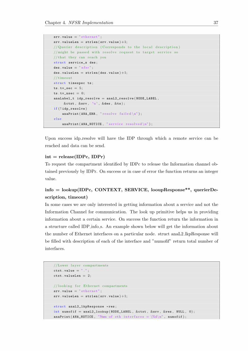
Chapter 4. NFSR Implementation 37
srv . value = ” ethe rne t ” ;
srv . valueLen = strlen ( srv . value )+1;
// Quer ier d e s c r i p t i o n ( Corresponds to the l o c a l d e s c r i p t i o n )
//might be passed with r e s o l v e r eque s t to t a r g e t s e r v i c e so
// that they can reach you
s t r u c t service_s des ;
des . value = ” n f s r ” ;
des . valueLen = strlen ( des . value )+1;
// timeout
s t r u c t timespec ts ;
ts . tv_sec = 5 ;
ts . tv_nsec = 0 ;
anaLabel_t idp_resolve = anaL2_resolve ( NODE_LABEL ,
&ctxt , &srv , 'u ' , &des , &ts ) ;
i f ( ! idp_resolve )
anaPrint ( ANA_ERR , ” r e s o l v e f a i l e d \n” ) ;
e l s e
anaPrint ( ANA_NOTICE , ” s e r v i c e r e s o l v ed \n” ) ;
Upon success idp resolve will have the IDP through which a remote service can be
reached and data can be send.
int = release(IDPc, IDPr)
To request the compartment identified by IDPc to release the Information channel ob-
tained previously by IDPr. On success or in case of error the function returns an integer
value.
info = lookup(IDPc, CONTEXT, SERVICE, looupResponse**, querierDe-
scription, timeout)
In some cases we are only interested in getting information about a service and not the
Information Channel for communication. The look up primitive helps us in providing
information about a certain service. On success the function return the information in
a structure called IDP info s. An example shown below will get the information about
the number of Ethernet interfaces on a particular node. struct anaL2 lkpResponse will
be filled with description of each of the interface and ”numofif” return total number of
interfaces.
//Lower l ay e r compartments
ctxt . value = ” . ” ;
ctxt . valueLen = 2 ;
// look ing f o r Ethernet compartments
srv . value = ” ethe rne t ” ;
srv . valueLen = strlen ( srv . value )+1;
s t r u c t anaL2_lkpResponse *res ;
i n t numofif = anaL2_lookup ( NODE_LABEL , &ctxt , &srv , &res , NULL , 0) ;
anaPrint ( ANA_NOTICE , ”Num of eth i n t e r f a c e s = \%d\n” , numofif ) ;
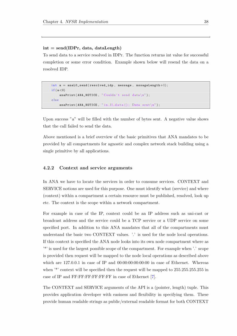
Chapter 4. NFSR Implementation 38
int = send(IDPr, data, dataLength)
To send data to a service resolved in IDPr. The function returns int value for successful
completion or some error condition. Example shown below will resend the data on a
resolved IDP.
i n t a = anaL0_send ( resolved_idp , message , mssageLength+1) ;
i f (a<0)
anaPrint ( ANA_NOTICE , ”Couldn ' t send data\n” ) ;
e l s e
anaPrint ( ANA_NOTICE , ” i n l l d a t a ( ) ; Data sent \n” ) ;
Upon success ”a” will be filled with the number of bytes sent. A negative value shows
that the call failed to send the data.
Above mentioned is a brief overview of the basic primitives that ANA mandates to be
provided by all compartments for agnostic and complex network stack building using a
single primitive by all applications.
4.2.2 Context and service arguments
In ANA we have to locate the services in order to consume services. CONTEXT and
SERVICE notions are used for this purpose. One must identify what (service) and where
(context) within a compartment a certain resource must be published, resolved, look up
etc. The context is the scope within a network compartment.
For example in case of the IP, context could be an IP address such as uni-cast or
broadcast address and the service could be a TCP service or a UDP service on some
specified port. In addition to this ANA mandates that all of the compartments must
understand the basic two CONTEXT values. ’.’ is used for the node local operations.
If this context is specified the ANA node looks into its own node compartment where as
’*’ is used for the largest possible scope of the compartment. For example when ’.’ scope
is provided then request will be mapped to the node local operations as described above
which are 127.0.0.1 in case of IP and 00:00:00:00:00:00 in case of Ethernet. Whereas
when ’*’ context will be specified then the request will be mapped to 255.255.255.255 in
case of IP and FF:FF:FF:FF:FF:FF in case of Ethernet [7].
The CONTEXT and SERVICE arguments of the API is a (pointer, length) tuple. This
provides application developer with easiness and flexibility in specifying them. These
provide human readable strings as public/external readable format for both CONTEXT
Chapter 4. NFSR Implementation 39
and SERVICE arguments and are favorable in the current implementation. The main
motivation behind using the ASCII format is the ease of use and ease of manipulation
using lexical manipulation tools. It also provides transparency to the user and hides the
actual implementation in compartments [7].
4.2.3 Recommended structure for a brick
brick template.h file
This file hides all of the MINMEX details from the software developer. It also provides
functionality of running a brick in user as well as in kernel space. It contains main
function for standalone user-space execution. It also contains an initialization function
for .so plug-in, and init and exit functions for kernel mode. These initialization functions
parse the arguments provided at execution, calls the brick init() function and attaching
of the bricks with MINMEX in case of standalone execution. System agnostic main
function for a brick is brick start(). A brick must not contain any other main function
[6].
Necessary functions
A brick which imports ”brick template.h” file must have these two functions.
� int brick start() This is the main function for a brick. When brick is attached
to the MINMEX this function is called and you can start communicating.
� void brick exit() This a default exit function for a brick. It does some required
functions before brick exit such as flushing entries in KVR garbage collection. It
is critical for an IDP in network compartment to inform other nodes about its un-
publishing of services. It is recommended that you explicitly un-publish services
and delete them.
It is recommended that functions provided in ANA are used otherwise if you use the
functions such as printf() it will cause problems in other execution mode (kernel) cross
compilation. The next section will describe ANA core abstractions which are important
to understand before starting implementation.
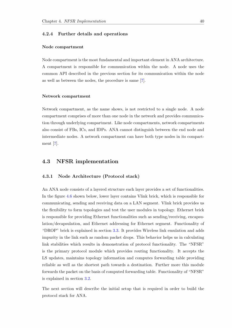
Chapter 4. NFSR Implementation 40
4.2.4 Further details and operations
Node compartment
Node compartment is the most fundamental and important element in ANA architecture.
A compartment is responsible for communication within the node. A node uses the
common API described in the previous section for its communication within the node
as well as between the nodes, the procedure is same [7].
Network compartment
Network compartment, as the name shows, is not restricted to a single node. A node
compartment comprises of more than one node in the network and provides communica-
tion through underlying compartment. Like node compartments, network compartments
also consist of FBs, ICs, and IDPs. ANA cannot distinguish between the end node and
intermediate nodes. A network compartment can have both type nodes in its compart-
ment [7].
4.3 NFSR implementation
4.3.1 Node Architecture (Protocol stack)
An ANA node consists of a layered structure each layer provides a set of functionalities.
In the figure 4.6 shown below, lower layer contains Vlink brick, which is responsible for
communicating, sending and receiving data on a LAN segment. Vlink brick provides us
the flexibility to form topologies and test the user modules in topology. Ethernet brick
is responsible for providing Ethernet functionalities such as sending/receiving, encapsu-
lation/decapsulation, and Ethernet addressing for Ethernet segment. Functionality of
“DROP” brick is explained in section 3.3. It provides Wireless link emulation and adds
impurity in the link such as random packet drops. This behavior helps us in calculating
link stabilities which results in demonstration of protocol functionality. The “NFSR”
is the primary protocol module which provides routing functionality. It accepts the
LS updates, maintains topology information and computes forwarding table providing
reliable as well as the shortest path towards a destination. Further more this module
forwards the packet on the basis of computed forwarding table. Functionality of “NFSR”
is explained in section 3.2.
The next section will describe the initial setup that is required in order to build the
protocol stack for ANA.
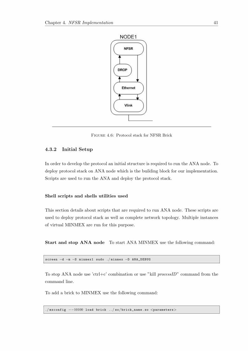
Chapter 4. NFSR Implementation 41
Figure 4.6: Protocol stack for NFSR Brick
4.3.2 Initial Setup
In order to develop the protocol an initial structure is required to run the ANA node. To
deploy protocol stack on ANA node which is the building block for our implementation.
Scripts are used to run the ANA and deploy the protocol stack.
Shell scripts and shells utilities used
This section details about scripts that are required to run ANA node. These scripts are
used to deploy protocol stack as well as complete network topology. Multiple instances
of virtual MINMEX are run for this purpose.
Start and stop ANA node To start ANA MINMEX use the following command:
screen −d −m −S minmex1 sudo . / minmex −D ANA_DEBUG
To stop ANA node use ’ctrl+c’ combination or use ”kill processID” command from the
command line.
To add a brick to MINMEX use the following command:
. / mxconfig −−10100 load brick . . / so/brick_name . so <parameters>
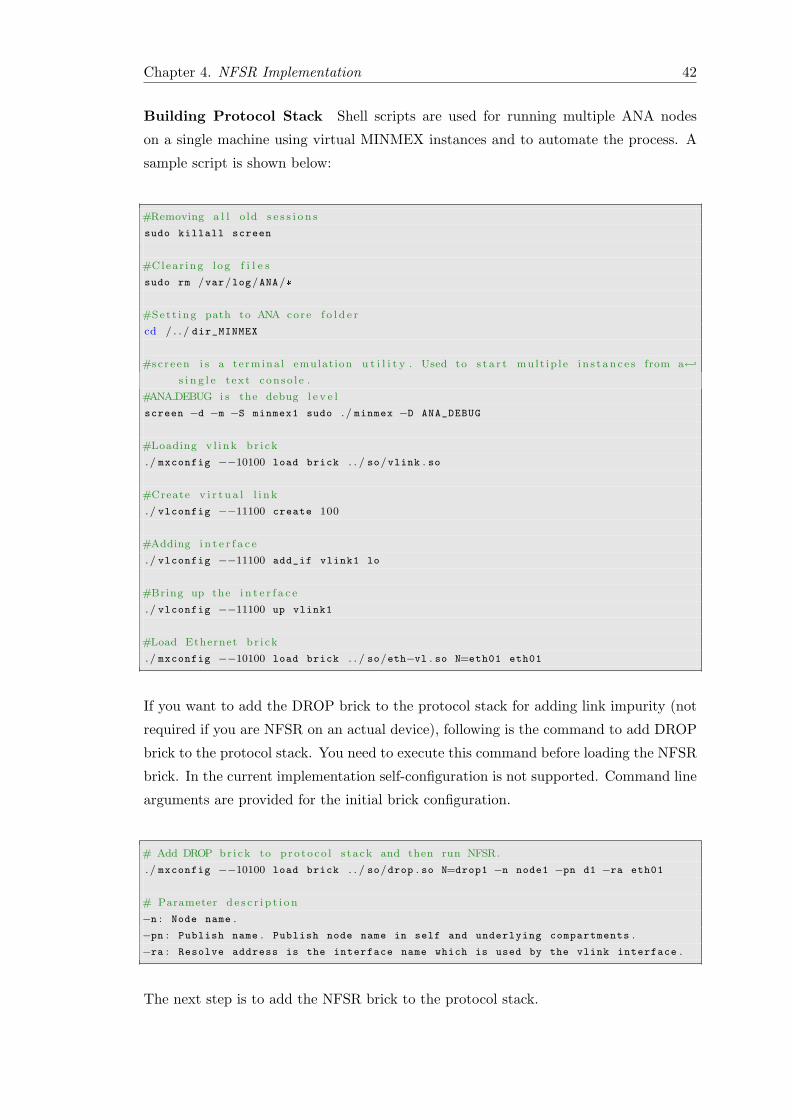
Chapter 4. NFSR Implementation 42
Building Protocol Stack Shell scripts are used for running multiple ANA nodes
on a single machine using virtual MINMEX instances and to automate the process. A
sample script is shown below:
#Removing a l l o ld s e s s i o n s
sudo killall screen
#Clear ing log f i l e s
sudo rm /var/log/ANA/*
#Set t ing path to ANA core f o l d e r
cd / . . / dir_MINMEX
#screen i s a te rmina l emulat ion u t i l i t y . Used to s t a r t mu l t ip l e i n s t an c e s from a←↩
s i n g l e t ex t conso l e .
#ANA DEBUG i s the debug l e v e l
screen −d −m −S minmex1 sudo . / minmex −D ANA_DEBUG
#Loading v l i nk br i ck
. / mxconfig −−10100 load brick . . / so/vlink . so
#Create v i r t u a l l i n k
. / vlconfig −−11100 create 100
#Adding i n t e r f a c e
. / vlconfig −−11100 add_if vlink1 lo
#Bring up the i n t e r f a c e
. / vlconfig −−11100 up vlink1
#Load Ethernet b r i ck
. / mxconfig −−10100 load brick . . / so/eth−vl . so N=eth01 eth01
If you want to add the DROP brick to the protocol stack for adding link impurity (not
required if you are NFSR on an actual device), following is the command to add DROP
brick to the protocol stack. You need to execute this command before loading the NFSR
brick. In the current implementation self-configuration is not supported. Command line
arguments are provided for the initial brick configuration.
# Add DROP br i ck to p ro to co l s tack and then run NFSR.
. / mxconfig −−10100 load brick . . / so/drop . so N=drop1 −n node1 −pn d1 −ra eth01
# Parameter d e s c r i p t i o n
−n : Node name .
−pn : Publish name . Publish node name in self and underlying compartments .
−ra : Resolve address is the interface name which is used by the vlink interface .
The next step is to add the NFSR brick to the protocol stack.
Chapter 4. NFSR Implementation 43
#Load NFSR br i ck
. / mxconfig −−10100 load brick . . / so/nfsr . so −n node1
# Parameter d e s c r i p t i o n
−n : Node name
If you want to add the clients on the node, add them to the protocol stack after the
NFSR brick, using the command
#Loading Cl i en t b r i ck
. / mxconfig −−10100 load brick . . / so/client . so −n client1
# Parameter d e s c r i p t i o n
−n : Client name used to publish in self and underlying compartment .
Once the protocol stack is build the next step is to initialize the protocol data structures.
The next section will explain the data structure initialization.
Data Structure Initialization
During initialization a node at first initializes its data structures such as neighbor, topol-
ogy, and forwarding tables for maintaining protocol data. This includes information
related to directly connected neighbors, network topology information and packet for-
warding information respectively. Node also initializes some other data structures such
as data structure for holding underlying Ethernet interface information as a node could
have more than one Ethernet interfaces and information channel information for each
of the interface needs to be maintained, data structure for maintaining a list of clients
attached to the node, data structures to hold the IDPs information for underlying brick,
and data structure to maintain monitoring data is also initialized.
Once the node initializes the data structures the next step is to setup initial commu-
nication which is achieved by publishing the services in the compartment so that the
services can be accessible locally as well as remotely (depending upon context). The
next section describes the service publishing.
Service Publishing
A node also maintains and publishes its services which are required to setup initial com-
munication. NFSR brick publishes its service with the name NFSR and scope “.”, which
is the scope for the local compartment described in section 4.2.2 , in local compartment.
Chapter 4. NFSR Implementation 44
Publishing the service with the name NFSR in local compartments will return the IDP
via which the service is accessible. To access a service it will first resolve the service
from the local compartment and Information channel (IC) will be obtained from the
compartment via which certain service will be accessible.
The DROP brick publishes its services with the name NFSR and with the node name
Noden , where n is the node number. These two names represent two different informa-
tion channels. NFSR is used to send control information such as LS updates and Noden is
used to send data packets. While sending control information or data to NFSR or Noden
respectively, two different ICs are used. These ICs are obtained from the compartment
by resolving a service with a particular name.
NFSR brick obtains the information for underlying Ethernet compartments by calling
lookup function which fills the struct anaL2 lkpResponse with the information for under-
lying Ethernet compartment and stores it in vector which will then be used to resolve
remote services using underlying compartment. Upon sending the data NFSR brick
resolves the remote service such as NFSR or Noden gets the IC and sends the data to it.
Protocol Timers
NFSR disseminates information based on inner and outer update scopes. The inner
update scope sends complete information for all of the nodes in the neighborhood. This
information is sent with higher frequency. Whereas the outer scope contains all of the
nodes that are outside the neighborhood and only partial aggregate information is sent
with lesser frequency. Both of the updates are sent to directly connected neighbors.
Timers are required to send these periodic updates. Each timer operates independent
of each other. The description for setting timer for ANA is as follows.
//Timer c a l l
Add_Timer ( time_in_milli_seconds , period , fix_clock , action_function , ←↩
function_data , func_data_length )
//Parameter d e s c r i p t i o n
time_in_milli_seconds : Sets time in milli seconds .
period : If set to ANA_PERIODIC restarts the time after it expires .
fix_clock : If set to ANA_ABSOLUTE reschedules the timer exactly in milliseconds ←↩
after the timer is supposed to expire .
action_function : Is the call to a function which will be triggered .
function_data : arguments to the function .
func_data_length : Arguments length .
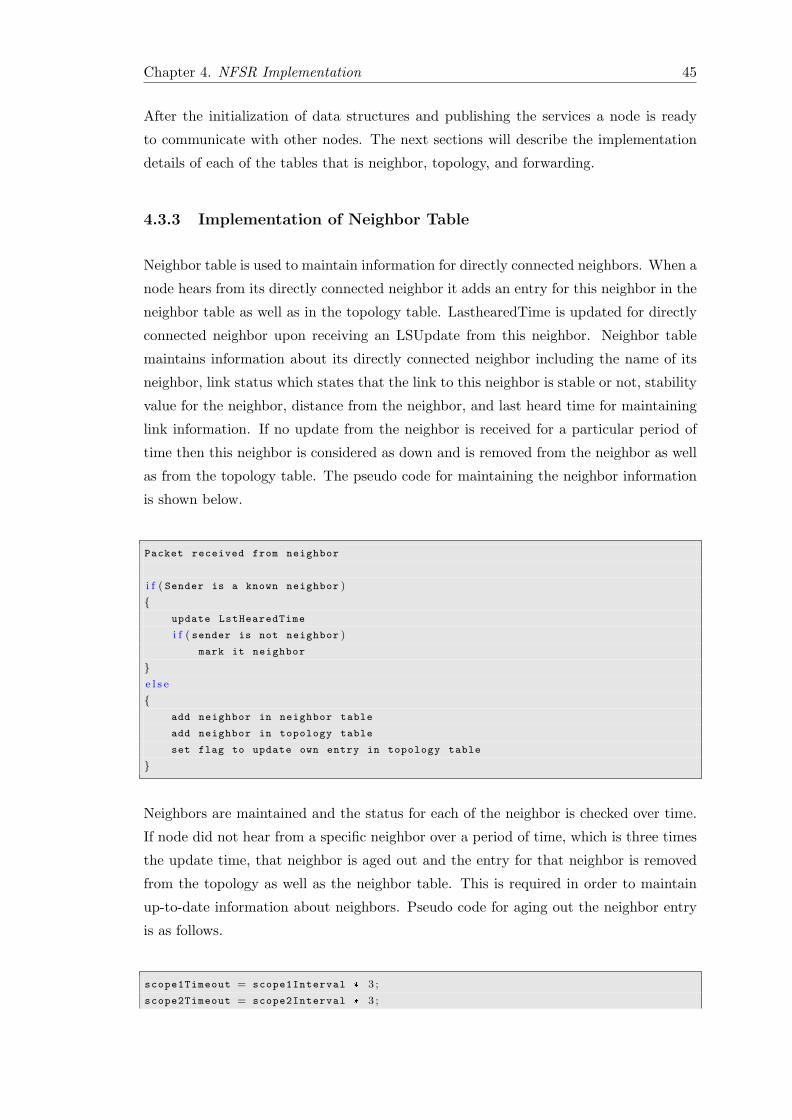
Chapter 4. NFSR Implementation 45
After the initialization of data structures and publishing the services a node is ready
to communicate with other nodes. The next sections will describe the implementation
details of each of the tables that is neighbor, topology, and forwarding.
4.3.3 Implementation of Neighbor Table
Neighbor table is used to maintain information for directly connected neighbors. When a
node hears from its directly connected neighbor it adds an entry for this neighbor in the
neighbor table as well as in the topology table. LasthearedTime is updated for directly
connected neighbor upon receiving an LSUpdate from this neighbor. Neighbor table
maintains information about its directly connected neighbor including the name of its
neighbor, link status which states that the link to this neighbor is stable or not, stability
value for the neighbor, distance from the neighbor, and last heard time for maintaining
link information. If no update from the neighbor is received for a particular period of
time then this neighbor is considered as down and is removed from the neighbor as well
as from the topology table. The pseudo code for maintaining the neighbor information
is shown below.
Packet received from neighbor
i f ( Sender is a known neighbor )
{update LstHearedTime
i f ( sender is not neighbor )
mark it neighbor
}e l s e
{add neighbor in neighbor table
add neighbor in topology table
set flag to update own entry in topology table
}
Neighbors are maintained and the status for each of the neighbor is checked over time.
If node did not hear from a specific neighbor over a period of time, which is three times
the update time, that neighbor is aged out and the entry for that neighbor is removed
from the topology as well as the neighbor table. This is required in order to maintain
up-to-date information about neighbors. Pseudo code for aging out the neighbor entry
is as follows.
scope1Timeout = scope1Interval * 3 ;
scope2Timeout = scope2Interval * 3 ;
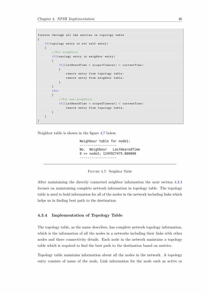
Chapter 4. NFSR Implementation 46
Iterate through all the entries in topology table
{i f ( topology entry is not self entry )
{//For ne ighbors
i f ( topology entry is neighbor entry )
{i f ( ( LstHeardTime + scope1Timeout ) < currentTime )
{remove entry from topology table ;
remove entry from neighbor table ;
}}e l s e
{//For non−ne ighbors
i f ( ( LstHeardTime + scope2Timeout ) < currentTime )
remove entry from topology table ;
}}
}
Neighbor table is shown in the figure 4.7 below.
Figure 4.7: Neighbor Table
After maintaining the directly connected neighbor information the next section 4.3.4
focuses on maintaining complete network information in topology table. The topology
table is used to hold information for all of the nodes in the network including links which
helps us in finding best path to the destination.
4.3.4 Implementation of Topology Table
The topology table, as the name describes, has complete network topology information,
which is the information of all the nodes in a networks including their links with other
nodes and there connectivity details. Each node in the network maintains a topology
table which is required to find the best path to the destination based on metrics.
Topology table maintains information about all the nodes in the network. A topology
entry consists of name of the node, Link information for the node such as active or
Chapter 4. NFSR Implementation 47
inactive, destination sequence number for maintaining up-to-date information, previous
sequence number, last heard time which is used for marking the link as alive, last update
time is maintained which is used to check when the last update was received from the
node, neighbor flag is maintained in the topology entry whether the node is neighbor or
not, link stability flag is set for the nodes which are on stable path, a flag for self entry is
maintained, number of neighbors for each topology entry is maintained, node neighbors
are maintained in a list of neighbors, link stability information for each topology entry
is also maintained.
The monitoring data is also maintained for each topology entry which contains informa-
tion for packets send and received, and packet count in last interval. This information
is used to calculate the path reliability to the destination. Packets count from the each
of the node is maintained. In this case only information regarding to directly connected
neighbors is maintained as the updates are only sent to the directly connected neighbors.
Two update scopes are introduced for the dissemination of topological information. The
inner update scope contains all of the nodes that currently regarded as neighbors. These
are the nodes that are inside the neighborhood. The outer update scope contains all of
the other nodes in the network. These nodes are not regarded as neighbors. The idea
of defining the update scopes is adapted from FSR [3] which states that accurate and
complete information is maintainted for the nodes in the inner most scope and maintains
fewer details for far end nodes. This reduces the number of update messages sent in
the network. All of the updates are sent to the directly connected neighbors. However
updates for both of the scopes are sent with different frequencies.
Inner update scope: LSUpdates for the inner update scope is sent more frequently.
This update contains complete information related to sending node. This information
includes node name and sequence number as well as the complete information about
its neighbors including neighbor name, distance, and link stability information. This
LSUpdate also includes the information about all of the nodes which are in node’s
neighborhood. For each neighborhood node only node name, sequence number, and a
list of all directly connected neighbors only containing node name is sent.
Outer update scope: LSUpdates for the outer update scope is sent less frequently.
This update does not include sender’s self information. It only contains the nodes that
are not in the neighborhood. Aggregated information is sent in this update at a lower
frequency. For each of the non-neighbor node, node name, sequence number and list of
neighbors only containing neighbor name is sent.
Pseudo code for sending LSUpdate for inner and outer update scope is given below.
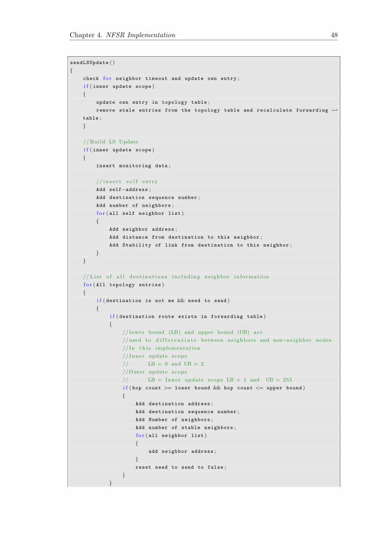
Chapter 4. NFSR Implementation 48
sendLSUpdate ( )
{check f o r neighbor timeout and update own entry ;
i f ( inner update scope )
{update own entry in topology table ;
remove stale entries from the topology table and recalculate forwarding ←↩
table ;
}
// Build LS Update
i f ( inner update scope )
{insert monitoring data ;
// i n s e r t s e l f entry
Add self−address ;
Add destination sequence number ;
Add number of neighbors ;
f o r ( all self neighbor list )
{Add neighbor address ;
Add distance from destination to this neighbor ;
Add Stability of link from destination to this neighbor ;
}}
// L i s t o f a l l d e s t i n a t i o n s i n c l ud ing neighbor in fo rmat ion
f o r ( All topology entries )
{i f ( destination is not me && need to send )
{i f ( destination route exists in forwarding table )
{// lower bound (LB) and upper bound (UB) are
//used to d i f f e r e n t i a t e between ne ighbors and non−neighbor nodes
// In t h i s implementation
// Inner update scope
// LB = 0 and UB = 2
//Outer update scope
// LB = Inner update scope LB + 1 and UB = 255
i f ( hop count >= lower bound && hop count <= upper bound )
{Add destination address ;
Add destination sequence number ;
Add Number of neighbors ;
Add number of stable neighbors ;
f o r ( all neighbor list )
{add neighbor address ;
}reset need to send to false ;
}}
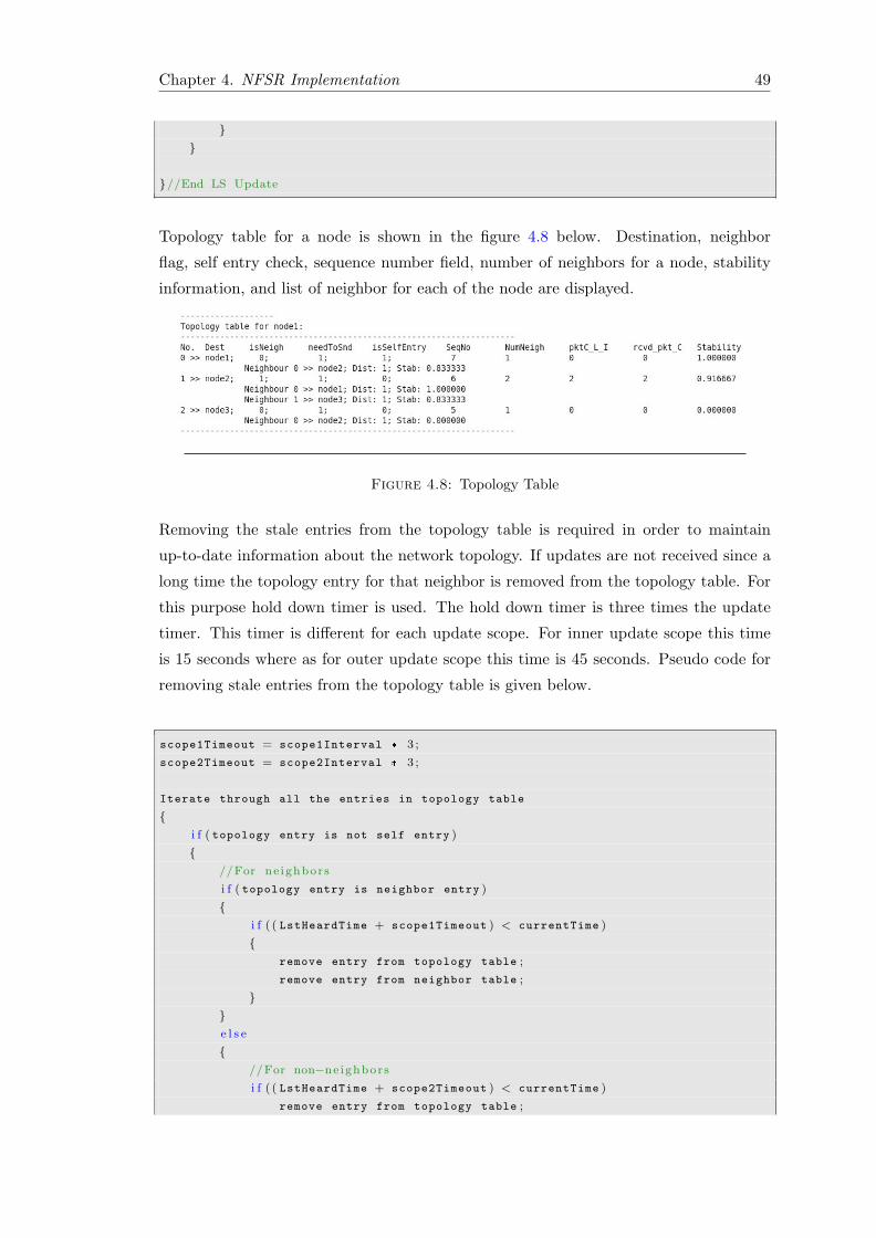
Chapter 4. NFSR Implementation 49
}}
}//End LS Update
Topology table for a node is shown in the figure 4.8 below. Destination, neighbor
flag, self entry check, sequence number field, number of neighbors for a node, stability
information, and list of neighbor for each of the node are displayed.
Figure 4.8: Topology Table
Removing the stale entries from the topology table is required in order to maintain
up-to-date information about the network topology. If updates are not received since a
long time the topology entry for that neighbor is removed from the topology table. For
this purpose hold down timer is used. The hold down timer is three times the update
timer. This timer is different for each update scope. For inner update scope this time
is 15 seconds where as for outer update scope this time is 45 seconds. Pseudo code for
removing stale entries from the topology table is given below.
scope1Timeout = scope1Interval * 3 ;
scope2Timeout = scope2Interval * 3 ;
Iterate through all the entries in topology table
{i f ( topology entry is not self entry )
{//For ne ighbors
i f ( topology entry is neighbor entry )
{i f ( ( LstHeardTime + scope1Timeout ) < currentTime )
{remove entry from topology table ;
remove entry from neighbor table ;
}}e l s e
{//For non−ne ighbors
i f ( ( LstHeardTime + scope2Timeout ) < currentTime )
remove entry from topology table ;
Chapter 4. NFSR Implementation 50
}}
}
After the successful implementation of topology table, the next section will focus on
computing forwarding table. The forwarding table helps in finding path to a destina-
tion with the information of next and previous hops. Next section will describe the
computation of forwarding table and how it is implemented.
4.3.5 Implementation of Forwarding Table
Every node in the network has its own topology table. As described above in section
4.3.4, topology table contains information for all the nodes in the network. There are
different algorithms that are used to compute forwarding table from the known topology
table, such as DUAL [19] and Dijkstra [20].
Algorithms either focuses on providing reliable path towards the destination or they
provide the shortest path towards destination. The main problem that could be encoun-
tered is that a reliable path may be a longer path, causing delay in end to end delivery of
packets. A shortest path may a non reliable path that causes link instabilities and could
change quite often and causes network bandwidth over utilization due to large number
of update packets. NFSR uses these two techniques of providing reliable and shortest
path and emphasizes on providing the reliable and shortest path towards destination.
In the initialization phase a neighborhood is created. Neighborhood contains all the
nodes that are considered as reliable. The computation of neighborhood is based on path
stability to the destination. In the current implementation, neighborhood is restricted to
a single hop count. On the basis of node stability there are three types of nodes, nodes
that are above stability limit, second the nodes within stability and threshold limit and
the nodes below threshold limit. If path to a destination is stable, that is above stability
limit, an entry for this node is created in the forwarding table and this node is added
to the stable list. On the other hand if a node fails to meet the stability limit, which
is stability within stability and threshold limits, the node is added to an unstable list.
The nodes in the unstable list are processed after all the nodes from stability list are
processed. Due to this forwarding table is populated initially using the stable path to
the destination. If a node stability is below thresh hold limit that node is not added to
any of the lists and the communication to this node will not be possible.
After the creation of neighborhood which now contains the nodes considered on a stable
path, Dijkstra algorithm is applied on topology table to find the shortest path to the
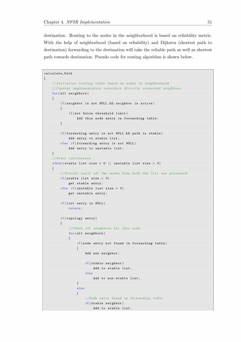
Chapter 4. NFSR Implementation 51
destination. Routing to the nodes in the neighborhood is based on reliability metric.
With the help of neighborhood (based on reliability) and Dijkstra (shortest path to
destination) forwarding to the destination will take the reliable path as well as shortest
path towards destination. Pseudo code for routing algorithm is shown below.
calculate_Path
{// I n i t i a l i z e rout ing tab l e based on nodes in neighborhood
//Current implementation con s i d e r s d i r e c t l y connected ne ighbors
f o r ( all neighbors )
{i f ( neighbor is not NULL && neighbor is active )
{i f ( not below threshold limit )
Add this node entry in forwarding table ;
}
i f ( forwarding entry is not NULL && path is stable )
Add entry to stable list ;
e l s e i f ( forwarding entry is not NULL )
Add entry to unstable list ;
}// Star t c a l c u l a t i o n
whi l e ( stable list size > 0 | | unstable list size > 0)
{// I t e r a t e un t i l a l l the nodes from both the l i s t are proce s s ed
i f ( stable list size > 0)
get stable entry ;
e l s e i f ( unstable list size > 0)
get unstable entry ;
i f ( list entry is NULL )
r e turn ;
i f ( topology entry )
{//Check a l l ne ighbors f o r t h i s node
f o r ( all neighbors )
{i f ( node entry not found in forwarding table )
{Add new neighbor ;
i f ( stable neighbor )
Add to stable list ;
e l s e
Add to non−stable list ;
}e l s e
{//Node entry found in forward ing tab l e
i f ( stable neighbor )
Add to stable list ;
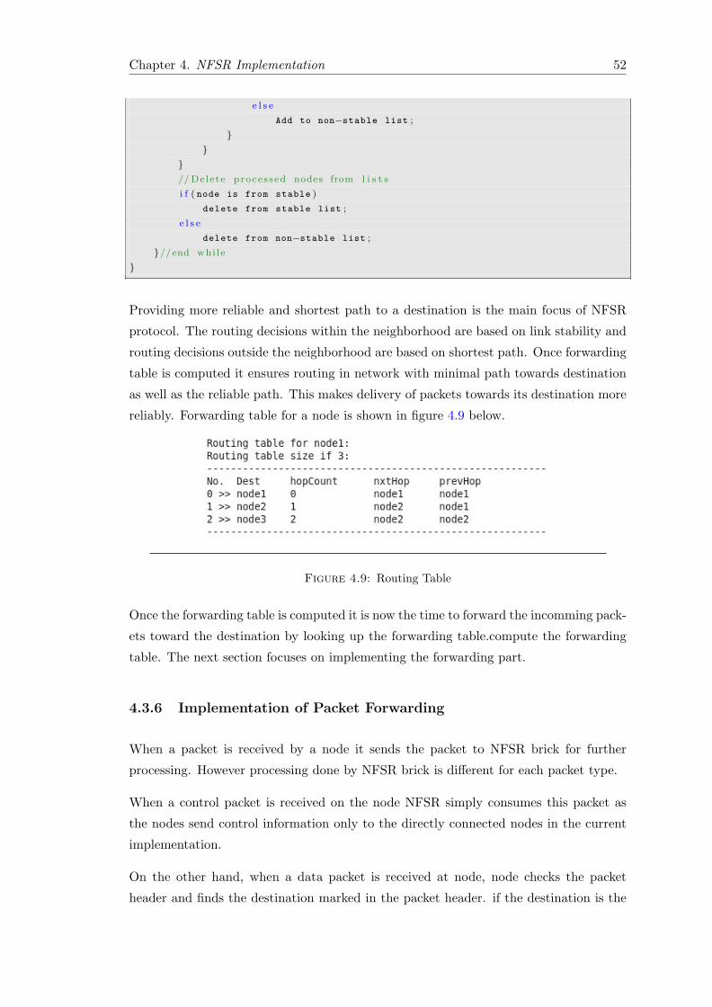
Chapter 4. NFSR Implementation 52
e l s e
Add to non−stable list ;
}}
}// Delete proce s s ed nodes from l i s t s
i f ( node is from stable )
delete from stable list ;
e l s e
delete from non−stable list ;
}//end whi l e
}
Providing more reliable and shortest path to a destination is the main focus of NFSR
protocol. The routing decisions within the neighborhood are based on link stability and
routing decisions outside the neighborhood are based on shortest path. Once forwarding
table is computed it ensures routing in network with minimal path towards destination
as well as the reliable path. This makes delivery of packets towards its destination more
reliably. Forwarding table for a node is shown in figure 4.9 below.
Figure 4.9: Routing Table
Once the forwarding table is computed it is now the time to forward the incomming pack-
ets toward the destination by looking up the forwarding table.compute the forwarding
table. The next section focuses on implementing the forwarding part.
4.3.6 Implementation of Packet Forwarding
When a packet is received by a node it sends the packet to NFSR brick for further
processing. However processing done by NFSR brick is different for each packet type.
When a control packet is received on the node NFSR simply consumes this packet as
the nodes send control information only to the directly connected nodes in the current
implementation.
On the other hand, when a data packet is received at node, node checks the packet
header and finds the destination marked in the packet header. if the destination is the
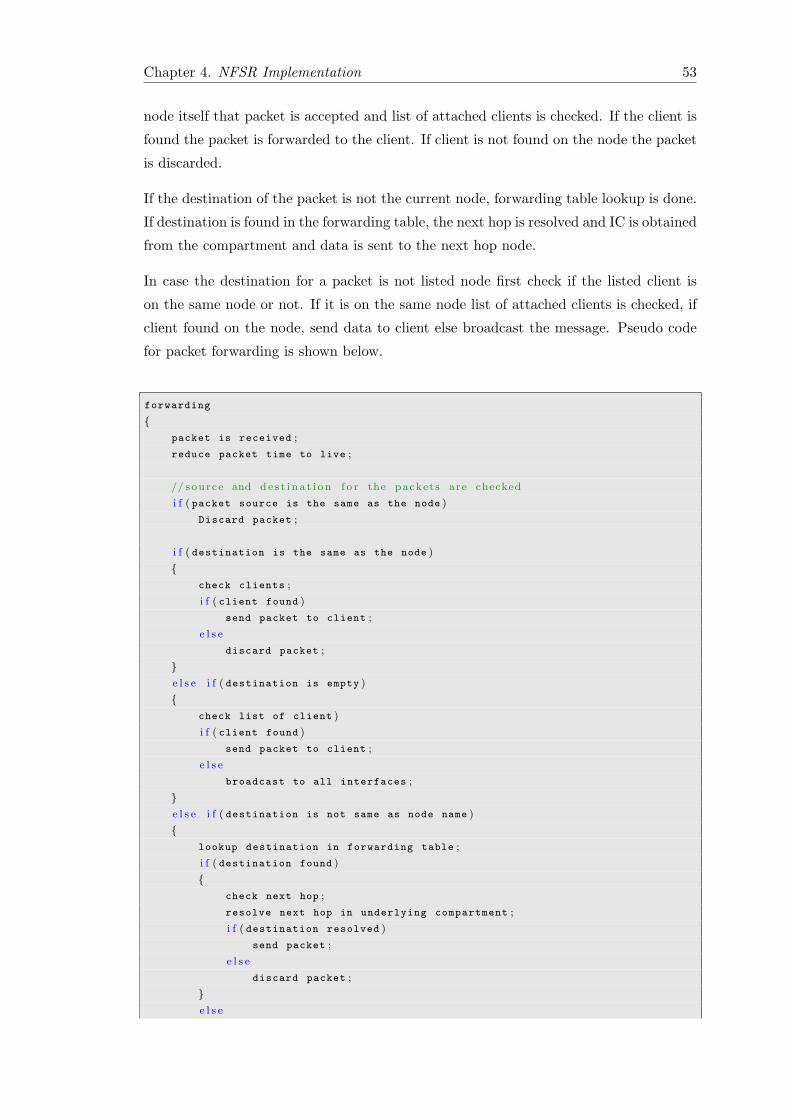
Chapter 4. NFSR Implementation 53
node itself that packet is accepted and list of attached clients is checked. If the client is
found the packet is forwarded to the client. If client is not found on the node the packet
is discarded.
If the destination of the packet is not the current node, forwarding table lookup is done.
If destination is found in the forwarding table, the next hop is resolved and IC is obtained
from the compartment and data is sent to the next hop node.
In case the destination for a packet is not listed node first check if the listed client is
on the same node or not. If it is on the same node list of attached clients is checked, if
client found on the node, send data to client else broadcast the message. Pseudo code
for packet forwarding is shown below.
forwarding
{packet is received ;
reduce packet time to live ;
// source and de s t i n a t i on f o r the packets are checked
i f ( packet source is the same as the node )
Discard packet ;
i f ( destination is the same as the node )
{check clients ;
i f ( client found )
send packet to client ;
e l s e
discard packet ;
}e l s e i f ( destination is empty )
{check list of client )
i f ( client found )
send packet to client ;
e l s e
broadcast to all interfaces ;
}e l s e i f ( destination is not same as node name )
{lookup destination in forwarding table ;
i f ( destination found )
{check next hop ;
resolve next hop in underlying compartment ;
i f ( destination resolved )
send packet ;
e l s e
discard packet ;
}e l s e
Chapter 4. NFSR Implementation 54
discard packet ;
}}
The next section focuses on the calculating link instabilities which is one of the key focus
of NFSR in providing reliable communication.
4.3.7 Implementation of Monitoring Part (Link stability)
Enabling more reliable routing in MANETs is the main motivation of this thesis work.
To achieve this goal we have introduced reliability metric in NFSR protocol. Stability
is the metric used for calculating path reliability. The value of stability lies between the
value of zero and one (0-1) where 0 is the minimum and 1 is the maximum reliability.
Link stability is the stability between two directly connected nodes. Link stability is
represented by using the following formula:
LinkStability =PacketsSent
PacketsReceived(4.1)
Packet counters are maintained on both sender and receiver side. When a node sends a
packet (Data/Control) it increments a sent packet counter. On the receiving side when a
node receives a packet it increments a receive packet counter for that particular neighbor
from which the packet is received. This information is maintained in the topology entry
of that neighbor.
Synchronization of monitoring interval is essential in order to calculate link stability.
Synchronization of monitoring interval is based on the interval count. When a node
sends the monitoring information, the receiver side reset the old interval and time for
old interval is stored in order to synchronize intervals and calculate link stability.
A node sends number of packets received from each directly connected neighbor and the
monitoring interval length to all its directly connected neighbors in LSUpdate. When
a node receives an LSUpdate it checks sender self entry flag. If it is set then it closes
the last interval and starts a new interval for the sender. A node further checks that if
it contains information for node it self it calculates the link stability for that particular
neighbor using the packet count and interval count. Link stability is calculated actively
to ensure up-to-date link stability information for all neighbors.
For example node1 is sending packets to node2 which is its directly connected neighbor.
Every time node1 sends a packet to node2 it increments a counter. When a packet is
Chapter 4. NFSR Implementation 55
received on node2 it checks that if the packet contains node1’s self entry (which contains
monitoring data). If packet contains node1 self entry it starts a new interval for that
node and increment the packet count for node1 in topology table. On next LSUpdate
node2 sends the information for all of its directly connected neighbors containing node
address, number of received packets, and interval count. When this packet is received at
node1 it checks that if it contains information for node1. When the self information is
found in the LSUpdate the node1 calculates the link stability by calculating the number
of packets sent divided by packets received.
The stability information provides minor overhead on the bandwidth of the link but
it provides a lot of benefits such as saving CPU cycles, saves power, as only necessary
information is sent to the other nodes, and results in communication on a reliable paths.
Once the link reliability is calculated for each of the neighbor, it is used to calculate
forwarding table. During the initial phase reliable paths to the destination for the
nodes in the neighborhood are calculated. Next, Dijkstra algorithm is applied to the
topology for calculating shortest path. This approach ensures more reliable path to the
destination as well as the shortest path.
4.4 Summary
This chapter details NFSR protocol implementation. Compartment API and ANA core
abstractions are discussed which are essential to understand for implementing solution
in ANA which is the development environment for NFSR protocol. Implementation
details for Neighbor, Topology, and Forwarding tables including functionality for each
of the components are discussed in detail. The next chapter will focus on performance
evaluation for NFSR and list results. Also it will provide guidelines for enhancing
protocol functionality.
Chapter 5
Experimentation and Evaluation
This chapter details about NFSR performance evaluation based on memory footprint,
topology and forwarding table creation in basic set of topologies and self-healing in case
of network failure. For that, in section 5.1 a criteria is developed that will be used as a
benchmark for evaluation of the proposed NFSR protocol. In section 5.2 the experiments
performed and results of the experiments are presented. Finally, section 5.3 discusses
NFSR optimization.
5.1 Performance Evaluation Criteria
Mobile devices lack in memory, CPU, and battery power. These resources are criti-
cal for the mobile nodes in MANET. If these resources are not properly utilized they
effect the performance as well as the up-time for a network node. Poor utilization of
these resources creates problems with application efficiency. There are a number of per-
formance evaluation criteria such as memory footprint, self-optimization, self-healing,
topology and routing table buildup time, data volume, CPU utilization, and update
frequency. For experimentation of NFSR following criteria are considered.
� Self-optimization: It is a measure that how efficient protocol performs its op-
erations and provides forwarding. Routing protocol in MANET should provide
optimized routing information as resources are limited in terms of memory, bat-
tery power, and bandwidth. The forwarding should be optimized and nodes in the
network should provide this without user interaction.
� Self-healing: It is a measure that how protocol maintains its routing information
in case of network failure. Nodes in MANET are continuously in motion. Nodes
56
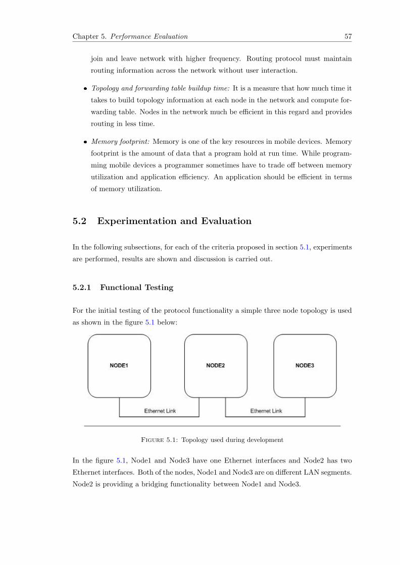
Chapter 5. Performance Evaluation 57
join and leave network with higher frequency. Routing protocol must maintain
routing information across the network without user interaction.
� Topology and forwarding table buildup time: It is a measure that how much time it
takes to build topology information at each node in the network and compute for-
warding table. Nodes in the network much be efficient in this regard and provides
routing in less time.
� Memory footprint: Memory is one of the key resources in mobile devices. Memory
footprint is the amount of data that a program hold at run time. While program-
ming mobile devices a programmer sometimes have to trade off between memory
utilization and application efficiency. An application should be efficient in terms
of memory utilization.
5.2 Experimentation and Evaluation
In the following subsections, for each of the criteria proposed in section 5.1, experiments
are performed, results are shown and discussion is carried out.
5.2.1 Functional Testing
For the initial testing of the protocol functionality a simple three node topology is used
as shown in the figure 5.1 below:
Figure 5.1: Topology used during development
In the figure 5.1, Node1 and Node3 have one Ethernet interfaces and Node2 has two
Ethernet interfaces. Both of the nodes, Node1 and Node3 are on different LAN segments.
Node2 is providing a bridging functionality between Node1 and Node3.
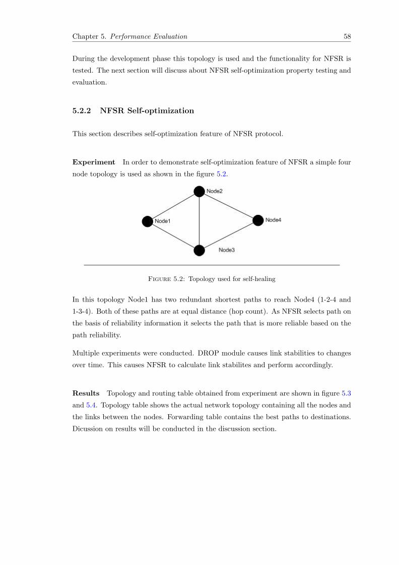
Chapter 5. Performance Evaluation 58
During the development phase this topology is used and the functionality for NFSR is
tested. The next section will discuss about NFSR self-optimization property testing and
evaluation.
5.2.2 NFSR Self-optimization
This section describes self-optimization feature of NFSR protocol.
Experiment In order to demonstrate self-optimization feature of NFSR a simple four
node topology is used as shown in the figure 5.2.
Figure 5.2: Topology used for self-healing
In this topology Node1 has two redundant shortest paths to reach Node4 (1-2-4 and
1-3-4). Both of these paths are at equal distance (hop count). As NFSR selects path on
the basis of reliability information it selects the path that is more reliable based on the
path reliability.
Multiple experiments were conducted. DROP module causes link stabilities to changes
over time. This causes NFSR to calculate link stabilites and perform accordingly.
Results Topology and routing table obtained from experiment are shown in figure 5.3
and 5.4. Topology table shows the actual network topology containing all the nodes and
the links between the nodes. Forwarding table contains the best paths to destinations.
Dicussion on results will be conducted in the discussion section.
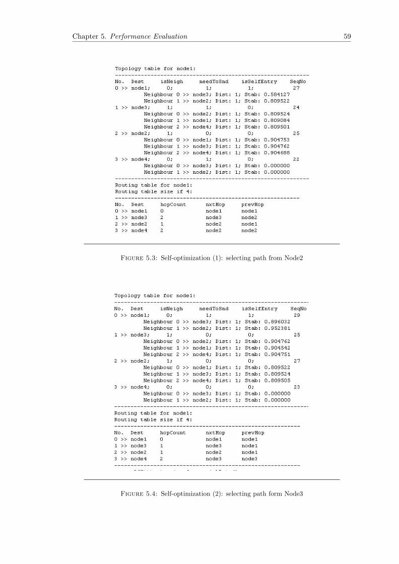
Chapter 5. Performance Evaluation 59
Figure 5.3: Self-optimization (1): selecting path from Node2
Figure 5.4: Self-optimization (2): selecting path form Node3
Chapter 5. Performance Evaluation 60
Discussion In figure 5.3 initially Node1 has link stability of 0.809522 for Node2 and
information obtained from Node2 for Node4 has link stability of 0.904688. Similarly
Node1 has link stability of 0.584127 for Node3 and information obtained from Node3
for Node4 has link stability of 0.809501. Node1 calculates the path reliability for Node4
as folows:
StabilityforNode1− > Node4(viaNode2) = Node2stabilityxNode4stabilitybyNode2
= 0.809522 ∗ 0.904688
= 0.732364
StabilityforNode1− > Node4(viaNode3) = Node3stabilityxNode4stabilitybyNode3
= 0.584127 ∗ 0.809501
= 0.472851
As can be seen from the calculation path stability from Node2 is higher as compared to
the path stability from Node3. NFSR selects the path for Node4 via Node2 as can be
seen from the forwarding table in figure 5.3.
When the stability changes over time, shown in 5.4, as nodes are constantly in motion.
Path stabilities are again calculated as follows:
StabilityforNode1− > Node4(viaNode2) = Node2stability ×Node4stabilitybyNode2
= 0.952381 ∗ 0.809505
= 0.770957
StabilityforNode1− > Node4(viaNode3) = Node3stability ×Node4stabilitybyNode3
= 0.896032 ∗ 0.904751
= 0.810685
From the results, calculated above, it is obvious that path from Node3 to Node4 is more
stable. NFSR selects the path for Node4 via Node3. It can be seen from the routing
table shown in 5.4.
The results shows that NFSR protocol is self-optimized and takes path stabilities into
account for selecting the more reliable path to destination.
5.2.3 NFSR Self-healing
This section describes self-healing feature for NFSR protocol. The topology setup used
in this experiment is the same as used in section 5.2.2, shown in figure 5.2.
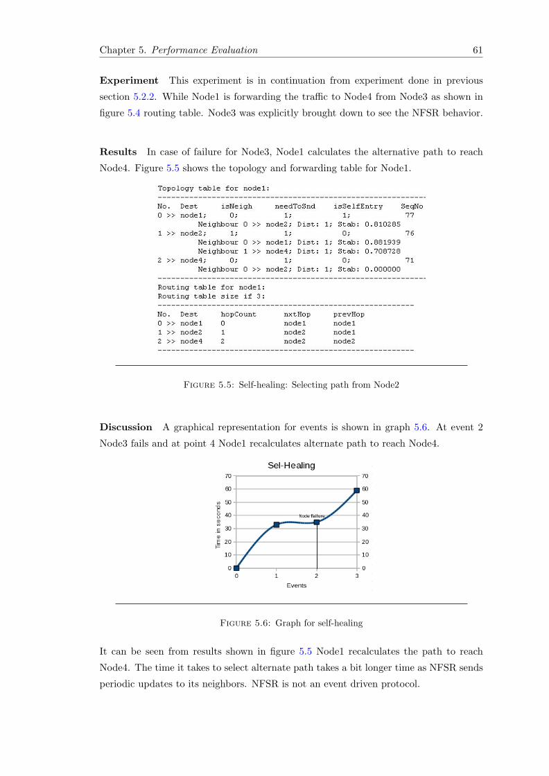
Chapter 5. Performance Evaluation 61
Experiment This experiment is in continuation from experiment done in previous
section 5.2.2. While Node1 is forwarding the traffic to Node4 from Node3 as shown in
figure 5.4 routing table. Node3 was explicitly brought down to see the NFSR behavior.
Results In case of failure for Node3, Node1 calculates the alternative path to reach
Node4. Figure 5.5 shows the topology and forwarding table for Node1.
Figure 5.5: Self-healing: Selecting path from Node2
Discussion A graphical representation for events is shown in graph 5.6. At event 2
Node3 fails and at point 4 Node1 recalculates alternate path to reach Node4.
Figure 5.6: Graph for self-healing
It can be seen from results shown in figure 5.5 Node1 recalculates the path to reach
Node4. The time it takes to select alternate path takes a bit longer time as NFSR sends
periodic updates to its neighbors. NFSR is not an event driven protocol.
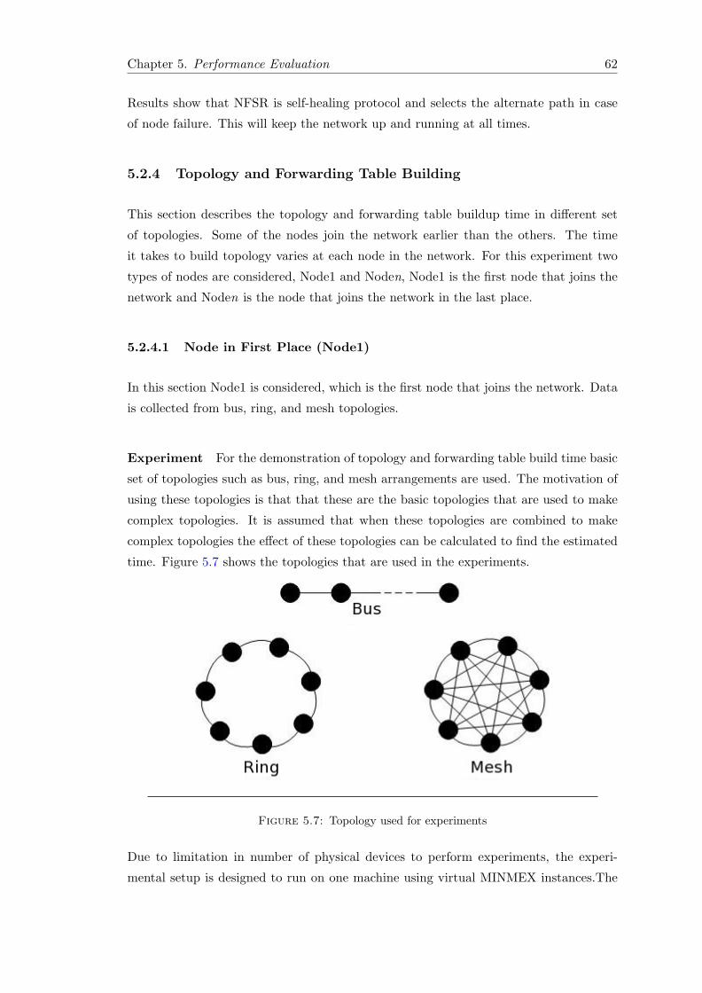
Chapter 5. Performance Evaluation 62
Results show that NFSR is self-healing protocol and selects the alternate path in case
of node failure. This will keep the network up and running at all times.
5.2.4 Topology and Forwarding Table Building
This section describes the topology and forwarding table buildup time in different set
of topologies. Some of the nodes join the network earlier than the others. The time
it takes to build topology varies at each node in the network. For this experiment two
types of nodes are considered, Node1 and Noden, Node1 is the first node that joins the
network and Noden is the node that joins the network in the last place.
5.2.4.1 Node in First Place (Node1)
In this section Node1 is considered, which is the first node that joins the network. Data
is collected from bus, ring, and mesh topologies.
Experiment For the demonstration of topology and forwarding table build time basic
set of topologies such as bus, ring, and mesh arrangements are used. The motivation of
using these topologies is that that these are the basic topologies that are used to make
complex topologies. It is assumed that when these topologies are combined to make
complex topologies the effect of these topologies can be calculated to find the estimated
time. Figure 5.7 shows the topologies that are used in the experiments.
Figure 5.7: Topology used for experiments
Due to limitation in number of physical devices to perform experiments, the experi-
mental setup is designed to run on one machine using virtual MINMEX instances.The
Chapter 5. Performance Evaluation 63
experiments was executed several times and it is considered that all the network links
are 100% healthy with no packet loss.
In the experiment two types of nodes in topology are considered for collecting data. First
is the Node1 which is the node that joins the network at first place and secondly the
noden which is last nodes that joined the network. Both of these nodes have different
behaviors in different set of topologies. The main motivation behind this is that, in
case of Node1 the topology table built time contains information propagation time plus
topology table build time. For Node1, the time calculation starts when the last node
joins the network. This time contains the information propagation time from noden to
Node1 and the topology table build time at Node1. For Noden, this time only contains
the topology table build time as the nodes with which Noden makes connections already
contains topology information which will then be exchanged with Noden. Multiple
experiments were conducted in order to collect data.
Experiments were conducted multiple times for each of the topologies described above.
For each of the topologies three, five, and seven nodes are used. This is because of the
limitation of physical machines for experiments. In this case only Node1 is observed for
each of the topology and for each of the different number of nodes in the network.
Results Results obtained from the above experimentation are shown. Table 5.1 shows
time it takes to build the topology table and 5.2 shows time it takes to build forwarding
table.
Table 5.1: Node 1 Topology Table Build Time* (seconds)
Nodes bus ring Mesh3 8 5 45 19 9 57 30 10 5
*Time = Propagation Delay + Build Time
Table 5.2: Node 1 Forwarding Table Build Time (seconds)
Nodes bus ring Mesh3 13 8 95 24 9 57 35 10 5
Discussion Data collected from experiments shown in tables 5.1 and 5.2 is used to
draw graphs, shown in 5.8 and 5.9 respectively.
Chapter 5. Performance Evaluation 64
Figure 5.8: Graph for Topology build time (Node1) for basic topologies
It can be observed from graph shown in 5.8, as the number of nodes in bus topology
increases, time to build topology table increases sequentially. Initially when the number
of nodes are less the time it takes is also less as the information propagation time is
less. With the increase in number of nodes the time it takes to propagate information
increases as network diameter is increased. As compared to bus, ring takes less time
in building topology table as the information is received from Node2 as well as from
Noden-1 and due to this the information propagation time is comparatively less in ring
as compared to bus. For mesh topology the time is almost the same even with the
increase in number of nodes in the network as there is one-to-one connectivity between
nodes.
Figure 5.9: Graph for forwarding table build time (Node1) for basic topologies
Graph in 5.9 shows that in case of bus topology with the increase in number of nodes
the time increases sequentially. In case of ring topology, increase in number of nodes
the time to compute forwarding table also increases with less proportion as compared to
bus as the information is received from more than one sources. In case of mesh topology
increase in number of nodes has no significant effect on forwarding buildup time due to
one-to-one links between nodes.
The next section will show the results obtained from the nth node in the network.
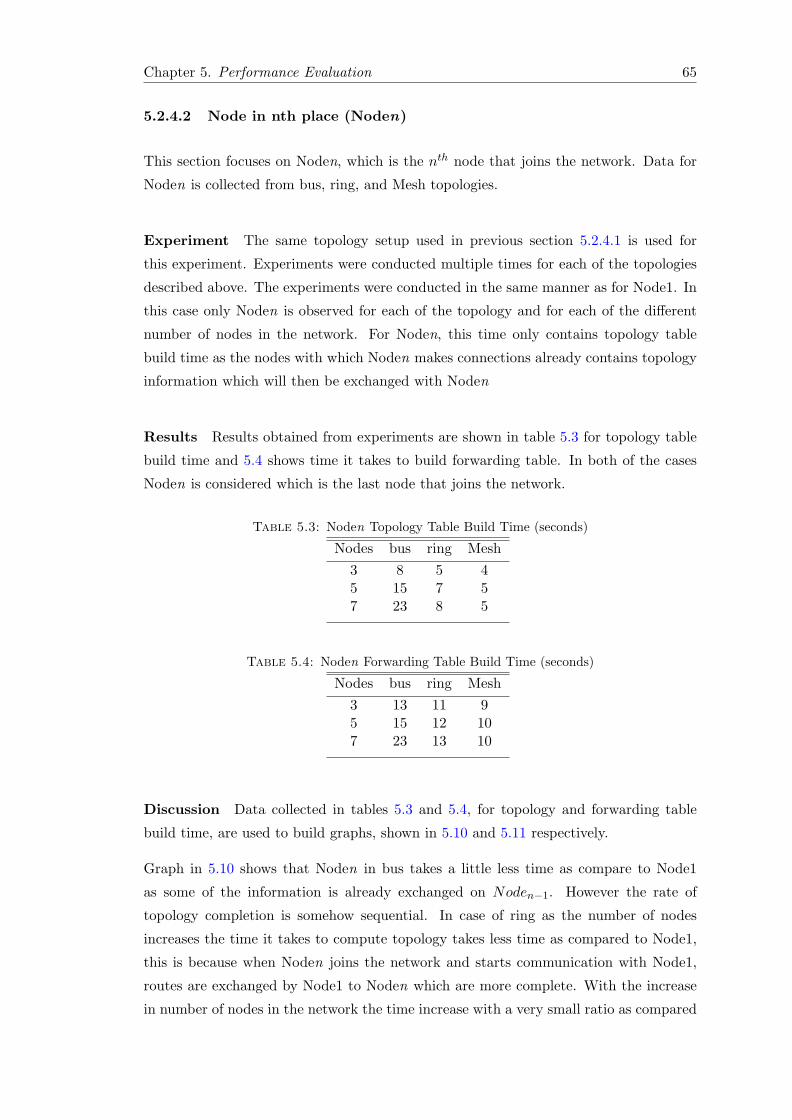
Chapter 5. Performance Evaluation 65
5.2.4.2 Node in nth place (Noden)
This section focuses on Noden, which is the nth node that joins the network. Data for
Noden is collected from bus, ring, and Mesh topologies.
Experiment The same topology setup used in previous section 5.2.4.1 is used for
this experiment. Experiments were conducted multiple times for each of the topologies
described above. The experiments were conducted in the same manner as for Node1. In
this case only Noden is observed for each of the topology and for each of the different
number of nodes in the network. For Noden, this time only contains topology table
build time as the nodes with which Noden makes connections already contains topology
information which will then be exchanged with Noden
Results Results obtained from experiments are shown in table 5.3 for topology table
build time and 5.4 shows time it takes to build forwarding table. In both of the cases
Noden is considered which is the last node that joins the network.
Table 5.3: Noden Topology Table Build Time (seconds)
Nodes bus ring Mesh3 8 5 45 15 7 57 23 8 5
Table 5.4: Noden Forwarding Table Build Time (seconds)
Nodes bus ring Mesh3 13 11 95 15 12 107 23 13 10
Discussion Data collected in tables 5.3 and 5.4, for topology and forwarding table
build time, are used to build graphs, shown in 5.10 and 5.11 respectively.
Graph in 5.10 shows that Noden in bus takes a little less time as compare to Node1
as some of the information is already exchanged on Noden−1. However the rate of
topology completion is somehow sequential. In case of ring as the number of nodes
increases the time it takes to compute topology takes less time as compared to Node1,
this is because when Noden joins the network and starts communication with Node1,
routes are exchanged by Node1 to Noden which are more complete. With the increase
in number of nodes in the network the time increase with a very small ratio as compared
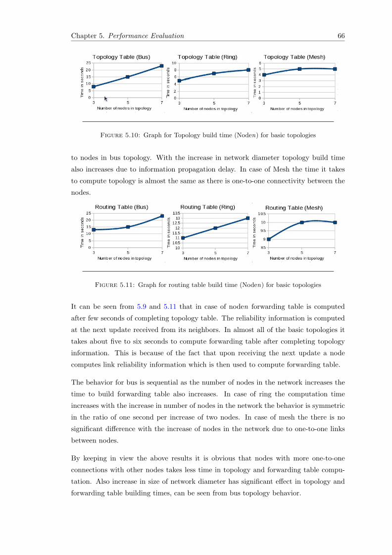
Chapter 5. Performance Evaluation 66
Figure 5.10: Graph for Topology build time (Noden) for basic topologies
to nodes in bus topology. With the increase in network diameter topology build time
also increases due to information propagation delay. In case of Mesh the time it takes
to compute topology is almost the same as there is one-to-one connectivity between the
nodes.
Figure 5.11: Graph for routing table build time (Noden) for basic topologies
It can be seen from 5.9 and 5.11 that in case of noden forwarding table is computed
after few seconds of completing topology table. The reliability information is computed
at the next update received from its neighbors. In almost all of the basic topologies it
takes about five to six seconds to compute forwarding table after completing topology
information. This is because of the fact that upon receiving the next update a node
computes link reliability information which is then used to compute forwarding table.
The behavior for bus is sequential as the number of nodes in the network increases the
time to build forwarding table also increases. In case of ring the computation time
increases with the increase in number of nodes in the network the behavior is symmetric
in the ratio of one second per increase of two nodes. In case of mesh the there is no
significant difference with the increase of nodes in the network due to one-to-one links
between nodes.
By keeping in view the above results it is obvious that nodes with more one-to-one
connections with other nodes takes less time in topology and forwarding table compu-
tation. Also increase in size of network diameter has significant effect in topology and
forwarding table building times, can be seen from bus topology behavior.
Chapter 5. Performance Evaluation 67
After the demonstration of self-healing, self-optimization, and topology and routing table
build time, the next section will discuss about the memory footprint which one of the
performance evaluation criteria.
5.2.5 Memory Footprint
This section will describe memory footprint for NFSR protocol for mobile devices.
Experiment Compilation for NFSR is done using gcc compiler. Compiling modules
for test-bed includes two modules, one is the NFSR protocol itself and the other is the
link emulation (DROP) module. Compiling the program generates nfsr.so and drop.so
files which are executed in ANA playground and interact with MINMEX.
Results The core NFSR protocol module is of size 255 KB which works with the
DROP module (emulating wireless links). The DROP module is of size 210.7 KB but
this module was created for test-bed only. For the deployment of NFSR on mobile
devices there is no need of having DROP module instead, as the device communicates
each other using wireless links. The size of NFSR module for the deployment on mobile
devices is 251.9 KB.
Discussion By looking into the results above NFSR module for mobile devices is small
in size. This means that it takes less memory on mobile devices.
The next section 5.3 details about the optimization techniques and suggestions are given
in order to improve the performance of NFSR protocol.
5.3 Optimization Techniques
This section details about optimization techniques. It details how to optimize NFSR
protocol in terms of protocol performance. It also suggests that how better results in
terms of topology and forwarding table build up times by using different set of topologies
can be achieved.
Chapter 5. Performance Evaluation 68
5.3.1 NFSR Optimization
Update Frequency
In order to build up the topology information quickly and to compute the forwarding
table the protocol need to send the updates to its neighbors in a more frequent manner.
With more frequent updates it consumes more resources in terms of battery power,
processing power, and bandwidth. As we know that battery is one of the key resources
in mobile nodes. There is a trade-off in terms of battery power and topology build time
at each node in the network.
Data Structures
The protocol was built for ANA architecture as a proof of concept. Efficiency in terms of
memory utilization is important for a protocol especially on a mobile device as memory
is one of the limited resource in mobile nodes. Protocol should utilize the memory in an
efficient manner. More optimized data structures can be used for maintaining protocol
information. In the current implementation vectors are used for keeping the information
for neighbor, topology, and forwarding tables. There is a trade-off in terms of space and
response time. If we use linked list the space will be optimized to some extent but the
retrieval time will be increase.
One of the good solution is to use hash tables for maintaining neighbor, topology, and
forwarding table. The information access will be much faster as well as the memory
consumption will be good.
Topology Build Time
As we have seen in section 5.2.4 different set of topologies take different amount of time
in setting up topology information as well as computing forwarding table on each node.
Furthermore the location of node in the topology also effects the build time. There is
no specific solution that can be suggested.
During experimentation, by running NFSR for multiple times in different set of topolo-
gies and by looking in to the results shown in tables 5.1, 5.2, 5.3, and 5.4. It is obvious
that topology in which nodes are more tightly connected to each other (Mesh) takes less
time in building topology and forwarding table. It can be said that if a node joins the
network and connects to more than one node in the network, the time it takes will be
less. The time of topology is inversely proportional to number of links a node have with
Chapter 5. Performance Evaluation 69
other nodes and the diameter of the network. If a network has larger diameter than the
information propagation time will then be added accordingly.
5.4 Summary
This chapter list performance evaluation for NFSR protocol. Tools used to for con-
ducting performance evaluation are listed. Self-optimization and self-healing property
is demonstrated and results are shown. Memory footprint is listed. Topology and for-
warding build time is evaluated focusing on basic set of topologies including nodes in
bus, ring, and mesh. Optimization techniques are also listed. The next chapter lists
theses which are the key achievements of this thesis work.
Chapter 6
Theses
� Autonomous Network architecture is explored.
� More reliable routing is enabled in MANET.
� Self-optimization is achieved using reliability metric.
� Self-healing is achieved.
� It is now possible to have more reliable as well as shortest paths to the destination.
� Topology buildup time is measured for basic set of topologies.
� Forwarding table computing time is measured for basic set of topologies.
� Techniques to enhance protocol performance are provided in terms of design and
deployment.
70
Chapter 7
Conclusion and Outlook
7.1 Conclusion
The core aim of this thesis is to enable reliable routing in mobile ad hoc networks and
validate self-healing and self-optimization properties for autonomous communication
while keeping the routing overhead small.
As a part of this work reliable routing protocol, NFSR, is deployed using Autonomous
Network Architecture. The protocol enables reliable routing in mobile ad hoc networks
and validates self-healing and self-optimization properties for autonomous communica-
tion. Neighborhood concept is improved and is based on reliability metric for providing
more reliable communication in challenged environment. Link stability based on packet
drop ratio for calculating path reliability for a destination is implemented. Link emu-
lation module which emulates wireless links in terms of packet loss for demonstrating
protocol behavior is implemented. The Performance of NFSR protocol is evaluated by
demonstrating results for self-healing and self-optimization. Also topology and forward-
ing table building times are calculated using different set of basic topologies. NFSR
optimization techniques are also discussed to increase protocol performance.
7.2 Outlook
The neighborhood concept in current implementation is restricted to one hop count.
It can be further improved by extending the scope to more than one hop. Multiple
neighborhoods with multiple scopes can be explored which reduces the information dis-
semination overhead among neighbors. NFSR can be evaluated for supported speed of
mobile nodes. The effects of change in periodic updates can also be studied. In the
71

Chapter 7. Conclusion and Outlook 72
current implementation NFSR is implemented as a proof of concept. Protocol efficiency
can be further improved using hash tables for maintaining protocol information such as
neighbor, topology, and forwarding information.
Bibliography
[1] Rfc1122 - requirements for internet hosts - communication layers. Last accessed:
February 2009. URL http://www.faqs.org/rfcs/rfc1122.html.
[2] Internetworking technology handbook internetworking basics. Last accessed: May
2009. URL http://www.cisco.com/en/US/docs/internetworking/technology/
handbook/Intro-to-Internet.html#wp1020580.
[3] Tsu-Wei Chen Guangyu Pei, M. Gerla. Fisheye state routing: a routing scheme for
adhoc wireless networks. IEEE International Conference on Communications, 1:
70–74, June 2000.
[4] Ibm perspective on the state of information technology. Deliverable D.1.10, Last
accessed: April 2009. URL http://researchweb.watson.ibm.com/autonomic/
overview.
[5] Autonomous network architecture. Last accessed: April 2009. URL http://www.
ana-project.org.
[6] Ana core documentation. Deliverable D.1.10, .
[7] Ana blueprint second version. Deliverable D.1.9, .
[8] Randall Berry. Lecture 1: Introduction to communication networks. Last ac-
cessed: June 2009. URL http//www.ece.northwestern.edu/~rberry/ECE333/
Lectures/.
[9] J. Macker S. Corson. Rfc2501: Mobile ad hoc networking (manet): Routing proto-
col. January 1999. URL http://www.faqs.org/rfcs/rfc2501.html.
[10] P. Bhagwat C. E. Perkins. Highly dynamic destination-sequenced distance vector
routing protocol. SIGCOMM 1994 Conference on Communications Architectures,
pages 234–244, August 1994.
[11] P. Jacquet T. Clausen. Optimized link state routing protocol. October 2003. URL
http://tools.ietf.org/html/rfc3626.
73
http://www.cisco.com/en/US/docs/internetworking/technology/handbook/Intro-to-Internet.html#wp1020580
Bibliography 74
[12] M. Lewis R. Ogier, F. Templin. Topology dissemination based on reverse-path
forwarding (tbrpf). February 2004. URL http://www.ietf.org/rfc/rfc3684.
txt.
[13] S. Das C. Perkins, E. Belding-Royer. Ad hoc on-demand distance vector (aodv)
routing. July 2003. URL http://tools.ietf.org/html/rfc3561.
[14] D. Maltz D. Johnson, Y. Hu. The dynamic source routing protocol (dsr)for mobile
ad hoc networks for ipv4. February 2007. URL http://tools.ietf.org/html/
rfc4728.
[15] D.M. Kephart, J.O. Chess. The vision of autonomic computing. Computer, 36:
41–50, January 2003.
[16] Fabrizio Sestini. Situated and autonomic communications in ict. November 2004.
URL ftp://ftp.cordis.europa.eu/pub/ist/docs/fet/comms-64.pdf.
[17] Objectives of ana project. Last accessed: April 2009. URL http://www.
ana-project.org/web/about/0-objectives/start.
[18] R. Mortier J. Crowcroft, S. Hand. Plutrach: An argument for network pluralism.
ACM SIGCOMM 2003 Workshop, August 2003.
[19] J.J. Garcia-Lunes-Aceves. Loop-free routing using diffusing computations. IEEE /
ACM Transactions on Networking, 1:130–141, February 1993.
[20] E. W. Dijkstra. Shortest path problem: Dijkstra algorithm. Last accessed: June
2009. URL http://www-b2.is.tokushima-u.ac.jp/~ikeda/suuri/dijkstra/
Dijkstra.shtml.