

VAG KSSplus Hollow-Jet Discharge Valve · tied completely before the valve is dismantled. Special...
12
KAT-B 2021-B1 Edition 1.3 2017-12-13 VAG KSSplus Hollow-Jet Discharge Valve Operation and Maintenance Instructions
Transcript of VAG KSSplus Hollow-Jet Discharge Valve · tied completely before the valve is dismantled. Special...

KAT-B 2021-B1 Edition 1.3 2017-12-13
VAG KSSplus Hollow-Jet Discharge Valve
Operation and Maintenance Instructions

2 • VAG Operation and Maintenance Instructions
Contents VAG reserves the right to make technical changes and use mate-rials of similar or better quality without ex-press notice. The pic-tures are non-binding.
1 General 1
1.1 Safety 1
1.2 Proper use 1
1.3 Identification 1
2 Transport and Storage 1
2.1 Transport 1
2.2 Storage 2
3 Product features 2
3.1 Features and function description 2
3.2 Applications 3
3.3 Performance limits 3
3.4 Permissible and impermissible modes of operation 3
4 Installation into the pipeline 3
4.1 Conditions required on site 3
4.2 Installation location 4
4.2.1 Installations in the pipeline upstream and downstream of the valve 4
4.2.2 Stable flow 4
4.2.3 Flow velocity 4
4.2.4 Valve-specific particularities 4
4.3 Installation position 5
4.4 Assembly instructions and fittings 5
5 Set-up and operation of the valve 5
5.1 Visual inspection and preparation 5
5.2 Function check and pressure test 5
6 Actuators 6
6.1 General 6
6.2 Operating torques 6
6.3 Assembly of the electric actuator 6
7 Maintenance and repair 7
7.1 General safety instructions 7
7.2 Inspection and operation intervals 7
7.3 Maintenance work and replacement of parts 8
7.3.1 Design 8
7.3.2 Recommendations for the replacement of parts 8
7.3.3 Replacement of seals 8
7.3.4 Relubrication of the gearboxes 8
7.3.5 Cleaning and lubrication 8
8 Trouble-shooting 9
9 How to contact us 9

VAG Operation and Maintenance Instructions • 1
pressure, medium, temperature) please refer to the product-rela-ted documentation (KAT-A 2021).
For any deviating operating conditions and applications, the manufacturer’s written approval must be obtained!
These Operation and Maintenance Operation Instructions contain important information on the safe and reliable operation of the VAG KSSplus Hollow-Jet Discharge Valves.
Observing these Operation and Maintenance Instructions helps you to:
• Prevent hazards
• Reduce repair costs and down-time of the valve and/or the en-tire equipment
• Improve the operational safety and useful life of the equipment.
1.3 Identification
According to DIN EN 19 all valves bear an identification label spe-cifying the nominal diameter (DN), nominal pressure (PN), body material and the manufacturer’s logo.
A rating plate is attached to the body and contains at least the following information:
VAG Manufacturer’s name Valve type
DN Nominal diameter of the valve
PN Flange drilling hole pattern PN
PS maximum admissible operating pressure
Date of manufacture
2 Transport and Storage
2.1 Transport
For transportation to its installation site, the valve must be packed in stable packaging material suitable for the size of the valve. It must be ensured that the valve is protected against atmospheric influences and external damage. When the valve is shipped under specific climatic conditions (e.g. overseas transport), it must be specially protected and wrapped in plastic film and a desiccant must be added.
The factory-applied corrosion protection and any assemblies must be protected against damage by external influences during transport and storage.
1 General
1.1 Safety
These Operation and Maintenance Instructions must be observed and applied at all times along with the general “VAG Installation and Operation Instructions for Valves” (see www.vag-group.com / Category: Ins-tallation and Operation Instructions).
Arbitrary alterations of this product and the parts supplied with it are not allowed. VAG will not assume any liability for consequenti-al damage due to non-compliance with these instructions.
When using this valve, the generally acknowledged rules of tech-nology have to be observed (e.g. national standards). The instal-lation must only be carried out by qualified staff (see also Section 7.1 General safety instructions). For further technical information such as dimensions, materials or applications, please refer to the respective documentation (KAT-A 2021).
VAG valves are designed and manufactured to the highest stan-dards and their safety of operation is generally assured . However, valves may be potentially dangerous if they are operated impro-perly or are not installed for their intended use.
Everyone dealing with the assembly, disassembly, operation, maintenance and repair of the valves must have read and under-stood the complete Operating and Maintenance Instructions (also Accident Prevention Regulations and ANSI Z535).
Before removing any protective devices and/or performing any work on the valves, depressurise the pipeline section and ensure it is free of hazards. Unauthorised, unintentional and unexpected actuation as well as any hazardous movements caused by stored energy (pressurised air, water under pressure) must be prevented.
In case of equipment that must be monitored and inspected, all relevant laws and regulations, such as the Industrial Code, the Accident Prevention Regulations, the Ordinance of Steam Boilers and instructional pamphlets issued by the Pressure Vessels Study Group must be complied with. In addition, the local accident pre-vention regulations must be observed.
If a valve serving as an end-of-line valve is to be opened in a pres-surised pipeline, this should be done with the utmost care to pre-vent the emerging fluid from causing damage. Care must also be taken when closing the valve in order not to crush any limbs
When a valve needs to be dismantled from a pipeline, fluid may emerge from the pipeline or the valve. The pipeline must be emp-tied completely before the valve is dismantled. Special care needs to be taken in case of residue which may continue flowing.
1.2 Proper use
The VAG KSSplus Hollow-Jet Discharge Valve is a highly effective control and shut-off valve (discharge control valve) and is desig-ned for flange connection to the pipeline.
VAG KSSplus Hollow-Jet Discharge Valves are suitable to be used for control functions in water supply systems. They are main-ly used as discharge control valves and bottom-outlet valves in dams to dissipate the kinetic energy generated while the water is being discharged to prevent damage. Their principle of operation fundamentally differs from that of other valves, as they produce a hollow jet which is soft and aerated. Additionally, these valves have excellent control properties and need only low actuation forces.
For the respective technical application ranges (e.g. operating
Picture 1: Transport position - horizontal, use A (or alternative C) and B
A B
C

2 • VAG Operation and Maintenance Instructions
appropriate, also the hydraulic cylinder or electric actuator and the seals against dust and other dirt by adequate covering.
Do not remove the protective caps of the connections / flanges and the packaging materials until immediately prior to assembly.
The valve can be stored in ambient temperatures ranging from -20 °C to + 50 °C (protected by adequate covers). If the valve is stored at temperatures below 0 °C, it should be warmed up to at least +5° C before installation and before it is put into operation.
3 Product features
3.1 Features and function description
VAG KSSplus Hollow-Jet Discharge Valves are designed to ope-rate as control valves in water supply systems. Unlike butterfly valves and gate valves, which are used for shut-off purposes only, hollow-jet discharge valves meet the specific requirements of control operation.
The VAG KSSplus Hollow-Jet Discharge Valve has an axisymme-tric flow pattern with an annular opening cross section in any in-termediate throttling position. The interior pipe hood ensures that the flow will always break away at the front edge and that there will be no partial breakaways inside the valve which may result in vibrations. The jet guiding cone transforms the jet emerging at high speed into a conical hollow jet which is atomised due to lar-ge-surface air friction. In the process, an intensive conversion of energy takes place. The kinetic energy of the jet decreases in the direction the jet spreads to the fourth power of the jet diameter. This softens the impact of the jet so considerably that no special reinforcement of the outlet equipment is necessary (see Picture 3).
As a standard, the valve is supplied equipped with a double-bevel gearbox and an electric actuator (see Picture 4) which, if required, can also be located in the superior operation level and actuated via remote operation gear and headstock.
The rotary motion initiated by the actuator is symmetrically trans-mitted to both sides via the double-bevel gear. There two bevel gearboxes are located which in turn transmit the rotary motion to two threaded stems. These threaded stems ensure the opening and closing of the cylindrical sleeves in axial direction.
When transporting the VAG KSSplus Hollow-Jet Discharge Valve, it needs to be ensured that the cylindrical sleeve remains open. This is done to protect the sliding rails on the body shell below the cylindrical sleeve. To lift the valve using a crane, ropes and shack-les, use the lifting eye bolts marked with an arrow in Picture 1.
If appropriate, smaller VAG KSSplus Hollow-Jet Discharge Valves (DN < 1000) may also be transported in an upright position with the connection flange facing down (see Picture 2).
If the valve is equipped with actuators, it must be made sure that the actuators are safely stored/anchored and that the connections are not exposed to shunt loading.
For transport purposes and also to support assembly, lifting de-vices such as cables and belts must only be attached to the valve body. The length and positioning of the cables/belts must ensure that the valve is in a horizontal position during the entire lifting procedure.
For valves that have been factory-packed in transport crates (wooden crates), the centre of gravity of the entire unit must be taken into account. The centre of gravity is marked on each side of the crate at our factory and must be considered for all lifting operations.
2.2 Storage
The VAG KSSplus Hollow-Jet Discharge Valve must be stored in open position and, if necessary, be placed horizontally on its base.
The elastomeric parts (seals) must be protected against direct sunlight and/or UV light as otherwise their long-term sealing func-tion cannot be guaranteed. Store the valve in a dry and well ae-rated place and avoid direct radiator heat. Protect any assembly units important for the function such as the stem, stem nut and, if
Picture 2: Transport position - vertical on the connection flange
Picture 3: VAG KSS Hollow-Jet Valve with pipe hood and integrated aeration

VAG Operation and Maintenance Instructions • 3
As actuation alternatives, a handwheel or a hydraulic actuator are available as well as a pipe hood to bundle the emerging water jet (see Picture 3). If required, venting equipment can be provided or customised valves and actuators can be supplied.
Due to the welded design of hollow-jet discharge valves, the valves can be customised to meet the requirements of many cus-tomer-specific installation situations. Nominal diameters range from DN 400 to DN 2000.
3.2 Applications
The VAG KSSplus Hollow-Jet Discharge Valve in its standard ver-sion can be used for the following media due to its sealing mate-rials NBR:
• Water
• Raw water and cooling water
Other applications:
• Hydropower stations
• Dams
• Drinking water reservoirs
• Man-made reservoirs
• Storm water retaining basins
Specific properties:
• axisymmetric flow pattern
• high flow velocity possible (up to 25 m/s)
• vibration-free operation
• cavitation-free operation
• free discharge of sediments
• simple, robust design
• low maintenance and maintenance-friendly
• mechanical, electrical or hydraulic operation
• drop-tight seal
• excellent control properties
• relatively low actuation forces required
• up to DN 1600 no foundation (valve support) required
• energy conversion at the emergence of the water jet, which en-sures low strain of the material
• submerged installation possible, if required
• jacket pipe/sliding face of the cylindrical sleeves and slidingrails made of stainless steel
• can be adapted to customer-specific installation situations ifthis can be realised by welding
• adjustable/re-adjustable sliding shoe guides
• Replacement of the main seal possible without disassembly ofthe cylindrical sleeves
For the respective operating temperature limits, please refer to the product-related technical documentation (KAT-A 2021). In case of deviating operating conditions and applications, please consult the manufacturer.
3.3 Performance limits
The throughput depends on the head of water and the intended nominal width of the hollow-jet discharge valve. Both values can be calculated using VAG UseCAD®.
The maximum flow velocity inside the hollow-jet discharge valve should not exceed 25 m/s.
3.4 Permissible and impermissible modes of operation
The maximum operating temperatures and operating pressures specified in the technical documentation (KAT-A 2021) and on the valve rating plate must not be exceeded. The pressure applied to the closed valve must not exceed its rated pressure.
Permanent operation at an opening range of less than 10% should be avoided to prevent excessive wear of the valve seal lo-cated behind the discharge cone. When the VAG KSSplus Hollow-Jet Discharge Valve opens, the water jet is deflected at the outer edge of the cone in a labyrinthine fashion and diverted towards the profile seal ring that is exposed to the jet for some seconds while the valve begins to open. While the valve opens further, the jet, due to its hollow, conical shape changes direction and spreads radially like an umbrella (45°). In this way, the valve can control the water between 8 and 100% opening position.
4 Installation into the pipeline
4.1 Conditions required on site
When the valve is installed between pipeline flanges (e.g. when supplied as hollow-jet discharge valve with ventilation pipe and/or jet guiding pipe) the flanges/pipelines must be plane parallel and in true alignment. Misaligned pipelines must be aligned before the valve is installed as otherwise the pipeline will be exposed to impermissibly high forces during operation. It may be useful to ins-tall a lockable dismantling piece which eliminates and/or transmits the axial pipeline forces. In some installation situations it needs to be ensured that a removable intermediate or dismantling piece of sufficient length is provided which allows the installation and/or dismantling of the VAG KSSplus Hollow-Jet Discharge Valve.
In case of civil or construction works around the valve causing dirt (e.g. painting, masonry or working with concrete), the valve must be protected by adequate covering. Special attention needs to be paid to the welded-on sliding rails surfaces located on the cylind-rical pipe of the hollow-jet valve body, on which the rear sliding shoes run. Make sure that they are perfectly clean. This surface should not be greased to prevent caking of dirt.
For assembly in drinking water pipelines, suitable sealing mate-rials, lubricants and process materials must be used which are approved for use in drinking water pipelines.
Before putting the valve into operation, clean and purge the corre-sponding pipeline sections.
Picture 4: VAG KSS Hollow-Jet Valve with electric actuator

4 • VAG Operation and Maintenance Instructions
If it is not possible to provide the required damping section or if it is not long enough, this may result in tur-bulences in the flow accompanied by disturbing noise and vibrations which may affect the proper function of the equipment and/or deteriorate its control behaviour.
4.2.3 Flow velocity
The VAG KSSplus Hollow-Jet Discharge Valve is suitable for ope-ration at a maximum flow velocity of about ca. 25 m/s.
The higher the flow velocity, the more important it is to provide a sufficiently long damping section upstream of the VAG KSSplus Hol-low-Jet Discharge Valve (cf. Section 4.2.2).
If a damping section cannot be provided, the minimum flow ve-locity needs to be reduced according to the installation situation.
4.2.4 Valve-specific particularities
Basic calibration of the VAG sliding shoes may only be carried out by specialised VAG personnel. Valves may not be under pressure during the calibration process. It is also necessary to replace the locking washers.
• The standard versions of VAG KSSplus Hollow-Jet DischargeValves in nominal diameters of DN 400 to DN 2000 are designedfor a maximum head of raised water of 100 m. All flange drillingpatterns from PN 10 to PN 25 can be combined with the stan-dard version.
• VAG KSSplus Hollow-Jet Discharge Valve: discharge in a radialslope of 45°
• VAG KSSplus Hollow-Jet Discharge Valves are equipped with(re)adjustable sliding shoes, which reduces vibrations and re-sults in a longer service life.
• VAG KSSplus Hollow-Jet Discharge Valve with / without ventila-tion and pipe hood (air-enriched, softened discharge to the frontin flow direction)
• VAG KSSplus Hollow-Jet Discharge Valve with annular flangeand/ or wallpipe for mounting with anchor bolts or embeddingin concrete
• VAG KSSplus Hollow-Jet Discharge Valve with mechanical ope-ration: - can be operated via a handwheel - with electric actuator - directly mounted - with headstock / extension rods
• VAG KSSplus Hollow-Jet Discharge Valve, hydraulically opera-ted: - via hydraulic cylinders mounted to the side - within the face-to-face length (in the stilling water area) - upstream of the connection flange (in the preceding dry zone)
• VAG KSSplus Hollow-Jet Discharge Valve can be customisedto suit customer-specific requirements / installation situations
4.2 Installation location
The installation location of the valve must be selected to provide sufficient space for function checks and maintenance works (e.g. dismantling and cleaning of the valve).
If the valve is installed in the open, it must be protected against extreme atmospheric influences (e.g. formation of ice) by adequa-te covers.
If the valve is installed as an end-of-line valve, it must be made sure that the free outlet side cannot be accessed by non autho-rised persons.
Attention: pressure on the closed valve must not ex-ceed its nominal pressure (see KAT-A 2021).
To ensure the trouble-free function and long service life of the val-ve, several factors have to be taken into account when positioning the valve.
• Prevent pollution on the outside
• Horizontal installation position
• Function check at least once per year by opening / closing thevalve
• Provide access for inspection / suspension eyes (for disassem-bly) at the top of the VAG KSSplus Hollow-Jet Discharge Valve
• Provide a stilling basin of sufficient size
• If necessary, provide a water-free, grated ventilation accessopening (in case of VAG KSSplus Hollow-Jet Discharge Valveswith ventilation pipe)
• Make sure axial forces are properly absorbed
• Counter-flange of the VAG KSSplus Hollow-Jet Discharge Valvesufficiently supported by axial fins
• From DN 1600 on, brackets are to be provided under the VAGKSSplus Hollow-Jet Discharge Valve to absorb weight
4.2.1 Installations in the pipeline upstream and downstream of the valve
If any further shut-off or safety valves should be installed upstream of the hollow-jet discharge valve, it needs to be made sure they can resist the flow velocity corresponding to the crosssection of the pipeline or can be operated at maximum operating conditions, respectively. To prevent asymmetric flow, no elbows, T-pieces or components disturbing the flow should be installed immediately upstream of the hollow-jet discharge valve. Additionally, due to the high flow velocity, the pipeline upstream of the VAG KSSp-lus Hollow-Jet Discharge Valve needs to be supported by suitable foundations.
• The upper and lower temperature limits of the flow mediummust not be exceeded.
• The pressure PS is the maximum admissible operating pressurethat may be exerted on the closed valve.
• The extension of operating elements by levers etc. is prohibited
4.2.2 Stable flow
Quiet and even flow ensures vibration-free and low-noise move-ment of the water through the valve and pipeline. To achieve sta-ble flow, a straight damping section sized approx. 5 x DN should be provided upstream of the VAG KSSplus Hollow-Jet Discharge Valve (see Picture 5).
Picture 5: Arrangement in the pipeline
5 x DN
DN

VAG Operation and Maintenance Instructions • 5
4.3 Installation position
The VAG KSSplus Hollow-Jet Discharge Valves must be installed in a horizontal position. Any other installation position is not per-missible.
4.4 Assembly instructions and fittings
Check the valve for possible damage that it may have suffered during transport and storage. Protect the valve against dirt caused on the construction site by adequate covering until installation. Prior to installation, all components essential for proper function, such as the welded-on slide rails on the body shell, the guiding fins and the seat ring with rubber seal must be thoroughly cleaned to remove any dirt. The cylindrical sleeve must also be thoroughly cleaned to remove all dirt particles. VAG does not assume any liability for consequential damage caused by dirt, shot-blasting gravel residues etc.
The moving parts should be checked for proper operation prior to installation.
Should the valves be repainted later on, it must be ensured that no paint is applied to the moving parts. The identification plates must not be painted over either. If the equipment is sandblasted for cleaning prior to installation, these parts must be adequately covered. If solvents are used for cleaning, it must be ensured that the solvents do not destroy the seals of the pipeline or the valve.
For the assembly of the VAG KSSplus Hollow-Jet Discharge Valve it must be ensured that proper load suspension devices as well as means of transport and lifting devices are available.
The valve must only be suspended via its body. Any other ways of suspension may cause damage.
When connecting the valve with the pipeline flange, hexagon bolts and nuts with washers from flange to flange must be used in the through holes.
Fasten the bolts evenly and crosswise to prevent unnecessary tension and the resulting cracks or breaks. The pipeline must not be pulled towards the valve. Should the gap between valve and flange be too wide, this should be compensated by thicker seals, unless it can be compensated by a dismantling piece.
We recommend using steel-reinforced rubber seals to DIN EN 1514-1 Shape IBC. If you use flared flanges, these seals are man-datory.
In case of concrete-embedded valves or wall pipes, the working surfaces on the body shell and the guiding rails must be protec-ted against damage. If they are dirty, clean them immediately and check for possible damage.
While the valve is being installed, it must be ensured that the flan-ges of the upstream pipeline it is connected to are aligned and level with each other. Welding works on the pipeline must be per-formed before the valve is installed to prevent damage to the seals and the corrosion protection. Welding residues must be removed before the equipment is put into operation.
The pipeline must be laid in a way that prevents harmful pipeline forces from being transmitted to the valve body. Should construc-tion works near or above the valve not be completed yet, the valve must be covered to protect it from dirt.
5 Set-up and operation of the valve
5.1 Visual inspection and preparation
Before putting the valve and the equipment into operation, per-form a visual inspection of all functional parts. Check whether all bolted connections have been properly fastened.
For assembly, storage and transport the valves are factory-lubri-cated. If the valves are used in drinking-water pipelines, lubricants approved for use with foodstuffs or drinking water must be ap-plied.
Recommended lubricants:
• Cylindrical sleeve and seals: KLÜBERSYNTH VR 69-252 (withKTW approval for drinking water)
• Stem and stem nut: KLÜBERPLEX BE 31-502, in particular ifelectric actuators are used
Manufacturer: Klüber Lubrication, Munich, Germany
5.2 Function check and pressure test
After installation, the moving parts of the cleaned valve have to be opened and closed completely at least once and should be checked for trouble-free operation.
Warning! The pressure exerted on the closed valve must not exceed its maximum admissible operating pressure PS (see technical data sheet KAT-A 2021). In the standard version PS is 10 bar (100 m water column)!
The sizes of the stems and actuators allow the operation of the valve via a handwheel by one person. Extensions for operation are not permissible and may cause damage to the valve due to overloading.
Permissible
Impermissible
Horizontal installation position
Picture 6: Installation position of the valve

6 • VAG Operation and Maintenance Instructions
The cylindrical sleeve of the VAG KSSplus Hollow-Jet Discharge Valve travels axially and its travel is limited by the “setting of the actuator” when the valve is in open position and by the seat ring with seal when the valve is in closed position.
Limit position and torque adjustment are to be made according to the operation manuals provided by the respective manufacturers of the electric or hydraulic actuators.
Non-compliance with these regulations may result in danger of life and limb and/or cause damage to the pipeline system. If actu-ators powered by external sources of energy (electric, pneumatic or hydraulic) have to be disassembled from the valve, the safety instructions under Section 1.1 need to be observed and the exter-nal source of energy must be switched off.
6.2 Operating torques
Operating torques are the maximum required torques [in Nm] ac-ting on the actuator stem at full differential pressure including a safety factor of 1.5. If required, you can contact us for information about the respective torques and/or controlling torques for elec-tric actuators.
6.3 Assembly of the electric actuator
The electric actuator is mounted to the input flange of the gear. The actuator size is selected according to the maximum actuation elements.
The valve is switched off• position-dependent in Open position• position-dependent in Closed position
In its standard version, the VAG KSSplus Hollow-Jet Discharge Valve is operated via an electric actuator which has been pre-ad-justed during the factory test. To put the valve into operation, first bring it to intermediate position manually. Check the direction of rotation of the motor again by shortly starting the valve electrically. Afterwards check the shut-off function of the torque switches and limit switches in both directions by manual operation of the swit-ches in intermediate position. If required, reverse the polarity of the switches. The valve must not be electrically operated over its entire travel before the correct sense of rotation and the shut-off func-tion have been checked and ensured.
If the sense of direction is wrong, the limit switch and torque switch have no effect! If a headstock or driving linkage is used, it must be made sure that the input shaft of the gear and the shaft of the electric actuator are not rotated as the hollow-jet discharge valve was checked with the electric actuator mounted and the actuator was adjusted in the process.
6 Actuators
6.1 General
The adjustment of the limit stops (OPEN, CLOSE) must not be changed without the manufacturer’s consent.
For detailed information on gears and actuators, please refer to the operation manuals issued by the manufacturers of these com-ponents (e.g. AUMA, Rotork). In some cases the manuals need to be obtained by the user himself.
Picture 7: Gearbox markings

VAG Operation and Maintenance Instructions • 7
The switching points are factory-adjusted. The torque switches serve as overload protection in the intermediate positions. If the valve is retrofitted with an electric actuator, the position switches have to be adjusted after the actuator has been mounted. For the adjustment procedure, please refer to the operating manual issu-ed by the manufacturer of the electric actuator.
The relevant safety regulations of the VDI / VDE and the instruc-tions of the manufacturer of the electric actuator must be obser-ved.
When the items are delivered, the adjustment screws and the connection bolts of the gear and the electric actuator are sealed with labels and/or identified by colour markings. The removal or breaking of these identifications will result in the loss of the manufacturer’s warranty. If foreign matter gets stuck while the val-ve is being operated, the torque switch for the respective direction is activated and switches the motor off. Then the electric actuator can no longer be started in this position. First, the valve must be inspected and then it must be operated in the opposite direction.
Operation in inching mode is permissible as described below:
If the torque switch responds in intermediate position, the valve must be operated in opposite direction until the torque switch completely returns to its resting position. Only then must the valve be operated in the direction in which the malfunction occurred. By this procedure, the torques are reached which correspond to the torques adjusted at the torque switch. Additionally, the foreign matter may come loose and be washed out of the seat area.
Emergency manual operation (handwheel):
If the valve is operated via the handwheel of the electric actuator, the torque switches do not have any safety function. If foreign matter is jammed while the valve is in intermediate position, the higher operating forces required may damage the actuator com-ponents – especially in case of high reduction gearing.
Attention: If you feel resistance during manual emer-gency operation of the valve, turn the handwheel into the opposite direction by making several turns, befo-re turning it back into the direction in which the mal-function was identified (washing out of foreign matter). Operate the valve very carefully, avoiding excessive force, and flush the pipeline, if necessary.
7 Maintenance and repair
7.1 General safety instructions
Prior to the performance of inspection and maintenance work on the valve or its assemblies, shut-off the pressurised pipeline, depressurise it and secure it against inadvertent activation. De-pending on the kind and dangerousness of the fluid conveyed, comply with all required safety regulations!
After completing the maintenance works and before resuming operation, check all connections for proper fastening and tight-ness. Perform the steps described for initial set-up as described under Section 5 “Set-up and operation”.
A VAG KSSplus Hollow-Jet Discharge Valve is not self-locking. The actuator/the gear must not be disassembled as long as the valve is pressurised. This also applies in case the complete valve is dismantled.
Statutory and local provisions as well as the safety and accident prevention regulations must be observed and complied with at all times.
Any damage caused by electric current (amperage) and current flow must be prevented. For electrical connections, the general guidelines according to VDE must be observed. Couplings and connections must never be disassembled when they are under pressure.
Servicing, maintenance and inspection work as well as the repla-cement of spare parts must only be done qualified staff. The plant operator is responsible for determining the suitability of the staff or for ensuring that they have the relevant qualifications.
If the operator’s employees do not have the qualifications requi-red, they need to attend a training course. This training course can e.g. be held by VAG Service employees.
In addition to this, the plant operator needs to ensure that all em-ployees have understood these Operation and Maintenance Inst-ructions as well as all further instructions referred to in them.
Protective equipment such as safety boots, safety helmets, gogg-les, protective gloves etc. must be worn during all work requiring such protective equipment or for which such protective equip-ment is prescribed.
Improper or wrong use of the valve should be avoided. Prior to the performance of any work on the valve and equipment it must be ensured that the relevant pipeline section has been depressurised and/or de-energised.
7.2 Inspection and operation intervals
The valve should be checked for tightness, proper operation and corrosion protection “at least once per year” (DVGW Instruction Sheet W 392).
In case of extreme operating conditions inspection should be per-formed more frequently.
For inspection and maintenance work, no protective devices must be removed before the pipeline section in which the valve is ins-talled has been shut off and depressurised.
• Check the exterior condition of the valve including its actuator,clean if necessary and repair damaged places.
• Check the flanges for leak-freeness
• Check whether the valve and actuator run smoothly and operatethem over the entire travel, if possible (see Section 4).
• Check the body seal for tightness
• Check the gearbox connections for tightness
• Clean the working surfaces
• Check the condition of the cardan shafts and liners
We recommend operating the valve at regular intervals (several times per year) over its entire travel (open – close) to prevent de-posits accumulating on the slide faces of the cylindrical sleeves.

8 • VAG Operation and Maintenance Instructions
7.3.5 Cleaning and lubrication
The two threaded stems and the stem nuts must be free from dirt and always properly lubricated. For this purpose, lubricants approved for use with foodstuff and/or drinking water must be applied.
Recommended lubricants:
• Stem and stem nut: KLÜBERPLEX BE 31-502, in particular ifelectric actuators are used
Manufacturer: Klüber Lubrication, Munich, Germany
7.3 Maintenance work and replacement of parts
The required spare parts and the parts subject to wear and tear can be found in the order-related documentation.
7.3.1 Design
The design is composed of simple cylindrical and annular ele-ments. This allows the manufacture of the entire hollow-jet di-scharge valve as a welded assemblage. The valve consists of a cylindrical body pipe with a jet guiding cone at the outlet. The body is equipped with slide rails on which the (re)adjustable sli-ding shoes screwed in the cylindrical sleeve run. By way of the cylindrical sleeve, the discharge cross section between the cone surface and the jacket pipe is changed and thus the discharge rate is controlled. The valve can be actuated via an electric ac-tuator or a handwheel. The output drive is effected via a double-bevel gearbox with branches to the lateral bevel gearboxes which move the cylindrical sleeve via threaded spindles. The controller, actuator and gearbox are located outside the valve body and thus are easily accessible for inspection and maintenance. The requi-red actuating forces are relatively low, as essentially only frictional forces along the slide rail and inside the actuator must be over-come whose size hardly changes over the area of motion. The ad-ditional forces caused by the water flowing along the inner surface and end face of the cylindrical sleeves are very low.
The largest torque results when the cylindrical sleeve is pushed onto the sealing seat.
7.3.2 Recommendations for the replacement of parts
Sealing rings must be replaced whenever necessary. The replace-ment intervals depend on the operating conditions.
7.3.3 Replacement of seals
The tightness of the VAG KSSplus Hollow-Jet Discharge Valve in closed position is ensured by stainless sealing faces provided with an additional elastic auxiliary seal (profile seal ring) (Picture 8).
A separate seat ring transmits the sealing pressure. This threaded sealing ring can be removed and thus allows the replacement of a damaged elastic seal. An annular quadring seal prevents the leakage of fluids between the cylindrical sleeve and jacket pipe (Picture 9).
Should leaks occur at the body seal or the valve seal, these seals can be replaced. After the disassembly of the seat ring, the pro-file ring on the pipe cone can be removed. To disassemble the quadring seal (rear seal at the body shell (Picture 9) the cylindrical sleeve must be moved beyond closed position and disassembled. To be able to move the cylindrical sleeve beyond the sealing ring, the rear and front sliding shoes first need to be removed from the cylindrical sleeve.
When installing the cylindrical sleeve, it must be made sure that its adjustment is plane-parallel (can be adjusted via the lateral fixing of the stem nuts).
7.3.4 Relubrication of the gearboxes
Remove the cover of the double-bevel gearbox. Fill the hollows of the gearbox with grease, replace cover and seal.
Lubricant:
• FUCHS RENOLIT FEP 2 (article number A 7451125)
Relubricate every five years.
Picture 8: Metallic and elastic sealing in the seat
Picture 9: Profile seal
VAG Operation and Maintenance Instructions • 9
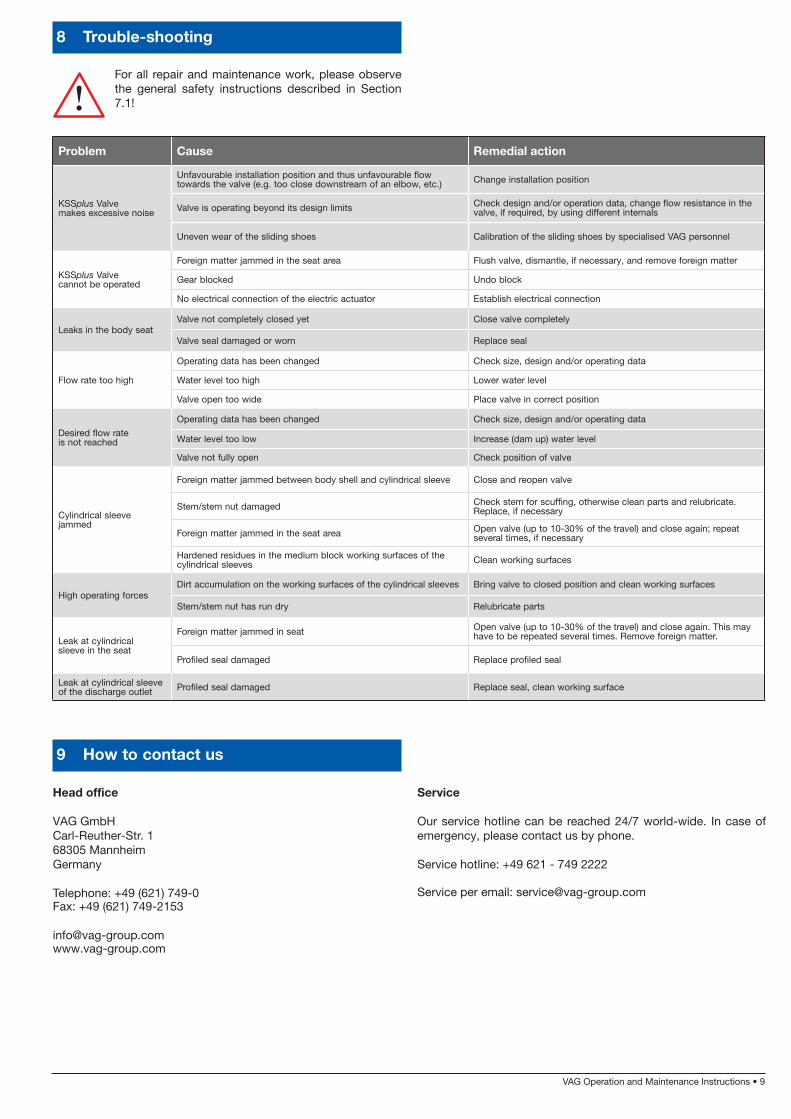
8 Trouble-shooting
For all repair and maintenance work, please observe the general safety instructions described in Section 7.1!
9 How to contact us
Head office
VAG GmbHCarl-Reuther-Str. 168305 Mannheim Germany
Telephone: +49 (621) 749-0 Fax: +49 (621) 749-2153
[email protected] www.vag-group.com
Problem Cause Remedial action
KSSplus Valve makes excessive noise
Unfavourable installation position and thus unfavourable flow towards the valve (e.g. too close downstream of an elbow, etc.) Change installation position
Valve is operating beyond its design limits Check design and/or operation data, change flow resistance in the valve, if required, by using different internals
Uneven wear of the sliding shoes Calibration of the sliding shoes by specialised VAG personnel
KSSplus Valve cannot be operated
Foreign matter jammed in the seat area Flush valve, dismantle, if necessary, and remove foreign matter
Gear blocked Undo block
No electrical connection of the electric actuator Establish electrical connection
Leaks in the body seatValve not completely closed yet Close valve completely
Valve seal damaged or worn Replace seal
Flow rate too high
Operating data has been changed Check size, design and/or operating data
Water level too high Lower water level
Valve open too wide Place valve in correct position
Desired flow rate is not reached
Operating data has been changed Check size, design and/or operating data
Water level too low Increase (dam up) water level
Valve not fully open Check position of valve
Cylindrical sleeve jammed
Foreign matter jammed between body shell and cylindrical sleeve Close and reopen valve
Stem/stem nut damaged Check stem for scuffing, otherwise clean parts and relubricate. Replace, if necessary
Foreign matter jammed in the seat area Open valve (up to 10-30% of the travel) and close again; repeat several times, if necessary
Hardened residues in the medium block working surfaces of the cylindrical sleeves Clean working surfaces
High operating forcesDirt accumulation on the working surfaces of the cylindrical sleeves Bring valve to closed position and clean working surfaces
Stem/stem nut has run dry Relubricate parts
Leak at cylindrical sleeve in the seat
Foreign matter jammed in seat Open valve (up to 10-30% of the travel) and close again. This may have to be repeated several times. Remove foreign matter.
Profiled seal damaged Replace profiled seal
Leak at cylindrical sleeve of the discharge outlet Profiled seal damaged Replace seal, clean working surface
Service
Our service hotline can be reached 24/7 world-wide. In case of emergency, please contact us by phone.
Service hotline: +49 621 - 749 2222
Service per email: [email protected]