Vacuum Technologyfor Ion · 2018-11-14 · Vacuum Technologyfor Ion Sources Paolo Chiggiato CERN...
37
5/30/2012 1 Vacuum Technology for Ion Sources Paolo Chiggiato CERN Technology Department Vacuum, Surfaces and Coatings Group Paolo Chiggiato ‐ CERN ‐ Vacuum Technology for Ion Sources 2 June 5th, 2012 Appendix 1. Basic Notions 2. Additional Examples of Electrical Analogy 3. Extra Info about Outgassing 5. Extra Info about Sputter Ion Pumps 6. Regeneration of NEG Pumps 7. Extra Info about Cryopumps. 1. Vacuum peculiarities of ion sources. 2. Gas flow in molecular regime a. Conductance and pumping speed. b. Evaluation of pressure profiles. c. Transient behaviour. 3. Electrical analogy 4. Outgassing 5. Gas pumping: a. Momentum transfer pumps (turbomolecular) b. Sputter ion pumps c. Getter pumps d. Cryopumps e. Comparison of pumps 6. Conclusions Outline
Transcript of Vacuum Technologyfor Ion · 2018-11-14 · Vacuum Technologyfor Ion Sources Paolo Chiggiato CERN...

5/30/2012
1
Vacuum Technology for Ion Sources
Paolo ChiggiatoCERN
Technology DepartmentVacuum, Surfaces and Coatings Group
Paolo Chiggiato ‐ CERN ‐ Vacuum Technology for Ion Sources 2June 5th, 2012
Appendix1. Basic Notions
2. Additional Examples of Electrical Analogy
3. Extra Info about Outgassing
5. Extra Info about Sputter Ion Pumps
6. Regeneration of NEG Pumps
7. Extra Info about Cryopumps.
1. Vacuum peculiarities of ion sources.
2. Gas flow in molecular regimea. Conductance and pumping speed. b. Evaluation of pressure profiles.c. Transient behaviour.
3. Electrical analogy
4. Outgassing
5. Gas pumping: a. Momentum transfer pumps
(turbomolecular)b. Sputter ion pumpsc. Getter pumpsd. Cryopumpse. Comparison of pumps
6. Conclusions
Outline

5/30/2012
2
Paolo Chiggiato ‐ CERN ‐ Vacuum Technology for Ion Sources 3
Vacuum Peculiarities of Ion Sources
June 5th, 2012
Ion sourceLow energy
beam transfer
High voltage RF
acceleratione
Gas injection Possible gas injection
Outgassing
Plasma formation Beam quality
prevent electrical breakdown
10‐2‐10‐3 mbar < ≈10‐5 mbar < ≈5x10‐7 mbar
Low pressure needs
Gas load
Pressure requirements (indicative)
o Ion sources are the only sector of accelerators in which gas is intentionally injected during operation (few exception exists).
o The main requirement of the ion source vacuum system is to evacuate the gas injected so that the vacuum in the rest of the LINAC is compatible with the high voltage RF acceleration and beam quality.
o Pressure in accelerators has a maximum in the ion source and its downstream beam pipe.
June 5th, 2012Paolo Chiggiato ‐ CERN ‐ Vacuum
Technology for Ion Sources4
Typical hydrogen gas load in proton ion sources: 10‐3÷10‐1 mbar l s‐1 (1016÷1018 molecules s‐1).
Only turbomolecular pumps withstand such a flux in continuous operation without deterioration.
To ensure lower pressure in the beam transport section, differential pumping is needed.
Most of the injected gas has to be removed before entering the RFQ.
Vacuum Peculiarities of Ion Sources
5/30/2012
3
June 5th, 2012Paolo Chiggiato ‐ CERN ‐ Vacuum
Technology for Ion Sources5
Basic Notions (see appendix 1)
• Ideal gas equation: (thermodynamic)
T (statistical mechanics)
• Maxwell‐Boltzmann model:m is the molecular mass [Kg]M is the molecular weight [Kg]φ
14
14
8
• Knudsen number:l is the mean free path of gas molecules, D typical distance of the vacuum system
• Molecular regime: 1 Collisions with the wall of the vacuum system more likely than those between molecules
• Gas flow Q in molecular regime: C is the gas conductance indipendent on pressure
• Gas conductance of a duct:Conductance of the duct aperture (A C’) x transmission probability ()
• Gas conductance of a wall slot:14
→∝1 A is the wall slot area
June 5th, 2012Paolo Chiggiato ‐ CERN ‐ Vacuum
Technology for Ion Sources6
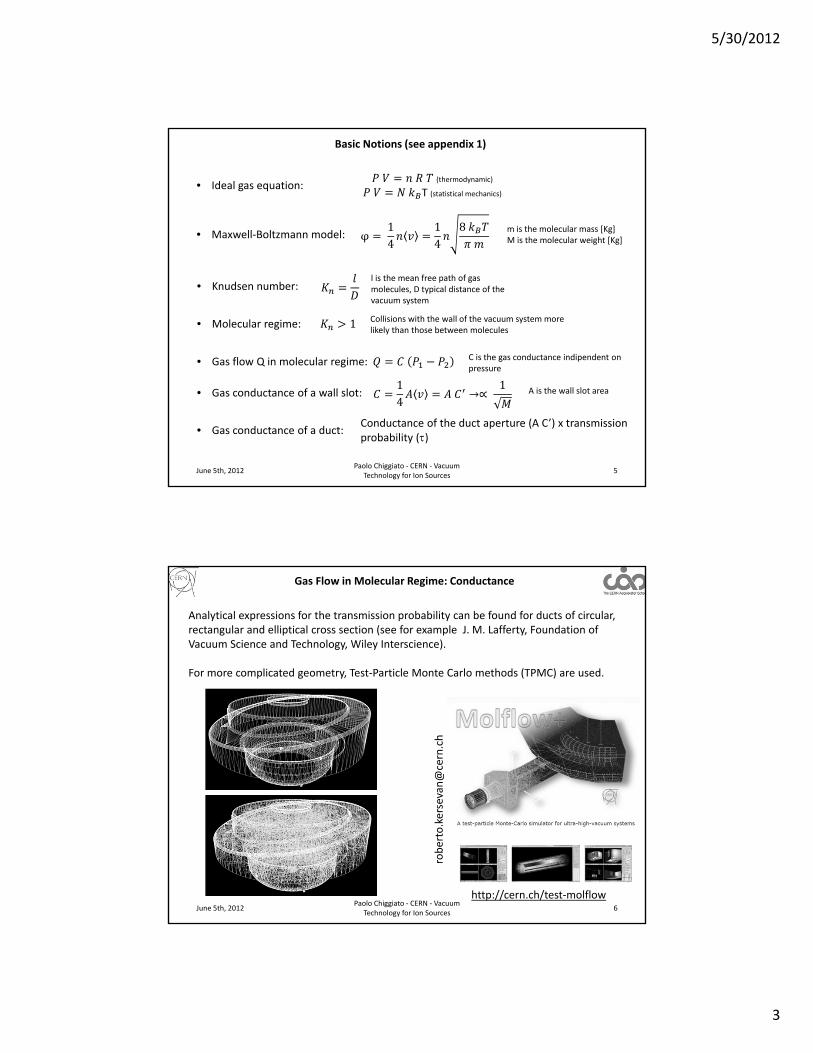
Gas Flow in Molecular Regime: Conductance
http://cern.ch/test‐molflow
Analytical expressions for the transmission probability can be found for ducts of circular, rectangular and elliptical cross section (see for example J. M. Lafferty, Foundation of Vacuum Science and Technology, Wiley Interscience).
For more complicated geometry, Test‐Particle Monte Carlo methods (TPMC) are used.
5/30/2012
4
June 5th, 2012Paolo Chiggiato ‐ CERN ‐ Vacuum
Technology for Ion Sources7
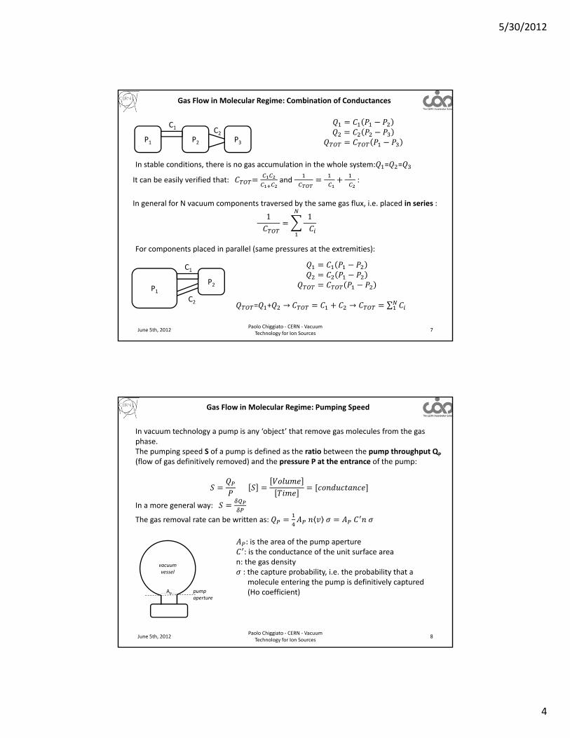
Gas Flow in Molecular Regime: Combination of Conductances
P1 P2 P3
C1 C2
It can be easily verified that: and
:
In general for N vacuum components traversed by the same gas flux, i.e. placed in series :
1
1
P1P2
C1
C2 = + → → ∑
In stable conditions, there is no gas accumulation in the whole system: = =
For components placed in parallel (same pressures at the extremities):
June 5th, 2012Paolo Chiggiato ‐ CERN ‐ Vacuum
Technology for Ion Sources8
Gas Flow in Molecular Regime: Pumping Speed
In vacuum technology a pump is any ‘object’ that remove gas molecules from the gas phase.The pumping speed S of a pump is defined as the ratio between the pump throughput QP
(flow of gas definitively removed) and the pressure P at the entrance of the pump:
In a more general way:
The gas removal rate can be written as:
:is the area of the pump aperture: is the conductance of the unit surface area
n: the gas density: the capture probability, i.e. the probability that a molecule entering the pump is definitively captured (Ho coefficient)
vacuum vessel
Ap pump aperture

5/30/2012
5
June 5th, 2012Paolo Chiggiato ‐ CERN ‐ Vacuum
Technology for Ion Sources9
Gas Flow in Molecular Regime: Pumping Speed
vacuum vessel
Ap pump aperture
As usual, in term of pressure and PV units:
From the definition of pumping speed:
S depends on the conductance of the pump aperture and the captureprobability .is in general not a constant; it may depend on many parameters including pressure, kind
of gas and quantity of gas already pumped.
The maximum pumping speed is obtained for and is equal to the conductance of the pump aperture.
ID [mm] H2 N2 Ar
36 448 120 100
63 1371 367 307
100 3456 924 773
150 7775 2079 1739
Maximum pumping speed [l s‐1]for different circular pump apertures
June 5th, 2012Paolo Chiggiato ‐ CERN ‐ Vacuum
Technology for Ion Sources10
Gas Flow in Molecular Regime: Effective Pumping Speed
vacuum vessel
P1
pump aperture
A gas flow restriction interposed between a pump and a vacuum vessel reduces the ‘useful’ pumping speed. The effective pumping speed Seff seen by the vacuum vessel is easily calculated:
S
P2
C
vesselaperture
1 1 1
For C>>S:
0.00
100.00
200.00
300.00
400.00
500.00
0 10 20 30
Conductance
S=250 l/s
S=1000 l/s
ExampleVessel and pump connected by a 100 mm diameter tube; nitrogen, S=250 l/s and 1000 l/s.
S effan
d C [l/s]
5/30/2012
6
June 5th, 2012Paolo Chiggiato ‐ CERN ‐ Vacuum
Technology for Ion Sources11
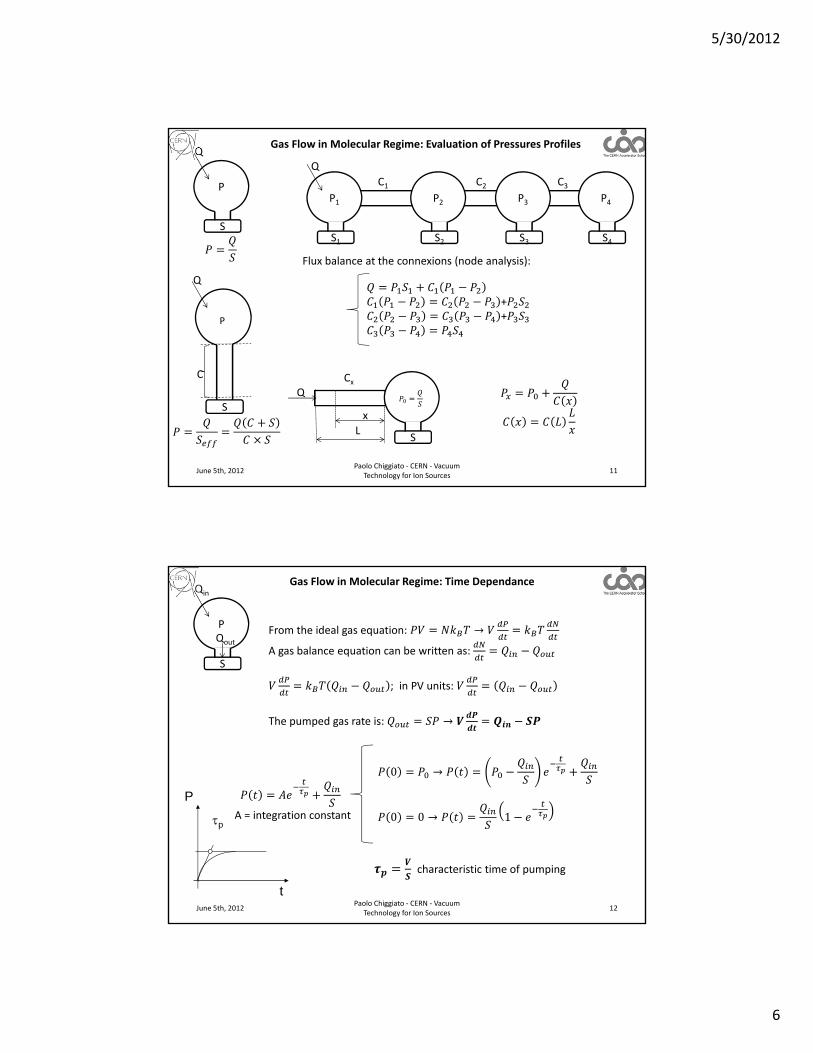
Gas Flow in Molecular Regime: Evaluation of Pressures Profiles
P
S
C
P
S
Q
Q
P1
S1
P2
S2
P3
S3
P4
S4
Q
C1 C2 C3
Flux balance at the connexions (node analysis):
++
S
CxQ
x
L
June 5th, 2012Paolo Chiggiato ‐ CERN ‐ Vacuum
Technology for Ion Sources12
t
P
p
Gas Flow in Molecular Regime: Time Dependance
P
S
Qin
From the ideal gas equation: →
A gas balance equation can be written as:
; in PV units:
The pumped gas rate is: →
Qout
0 →
0 0 → 1
characteristic time of pumping
A = integration constant
5/30/2012
7
June 5th, 2012Paolo Chiggiato ‐ CERN ‐ Vacuum
Technology for Ion Sources13
t
Gas Flow in Molecular Regime: Time Dependance
When Qin is a function of time:
Q
t
P
A = integration constant
For a network of vacuum chambers, systems of coupled differential equations for each chamber have to be solved.
However, a simpler method exists. It is based on the analogy between vacuum systems and electrical networks. Very powerful software is available for the time dependent analysis of electrical networks.
June 5th, 2012Paolo Chiggiato ‐ CERN ‐ Vacuum
Technology for Ion Sources14
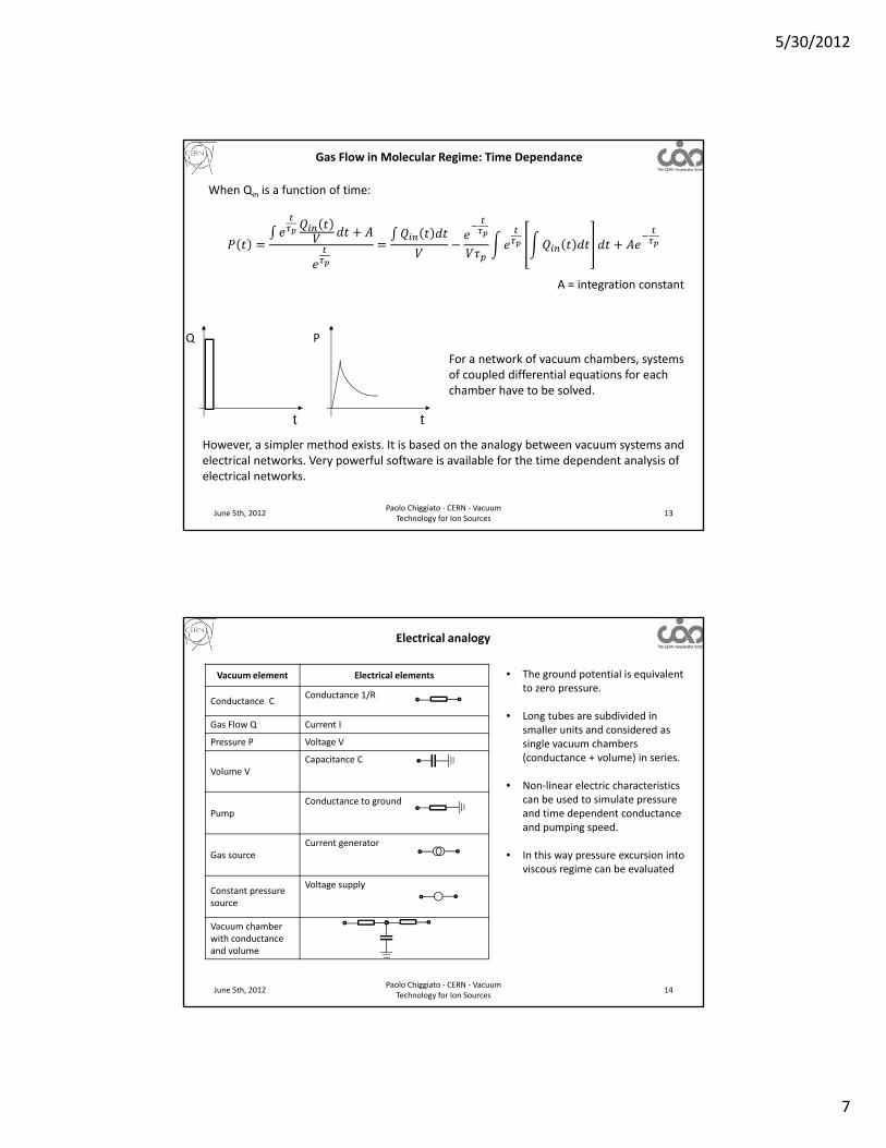
Electrical analogy
Vacuum element Electrical elements
Conductance CConductance 1/R
Gas Flow Q Current I
Pressure P Voltage V
Volume VCapacitance C
PumpConductance to ground
Gas sourceCurrent generator
Constant pressuresource
Voltage supply
Vacuum chamber with conductance and volume
• The ground potential is equivalent to zero pressure.
• Long tubes are subdivided in smaller units and considered as single vacuum chambers (conductance + volume) in series.
• Non‐linear electric characteristics can be used to simulate pressure and time dependent conductance and pumping speed.
• In this way pressure excursion into viscous regime can be evaluated

5/30/2012
8
June 5th, 2012Paolo Chiggiato ‐ CERN ‐ Vacuum
Technology for Ion Sources15
Electrical analogy
Simple example: differential pumpingP1 P2C
Q
V1V2
Q P1 P2C
V1 V2
S1 S2
A more complex example: part of the Linac4 H‐ source (from C. Pasquino et al., CERN, ATS/Note/2012/043 TECH)
June 5th, 2012Paolo Chiggiato ‐ CERN ‐ Vacuum
Technology for Ion Sources16
Outgassing
Materials of which a vacuum system is made of are spontaneous source of gas.
Two main categories of materials:
Metals
After state‐of‐art surface cleaning
• If not heated in situ: mainly H2O for the first months in vacuum, then also H2.
3 10
The source of H2O is recharged after each venting to air.
• If heated in situ (baked‐out): mainly H2. The outgassing rate can be assumed as constant; it depends on the accumulated effect of the previous thermal treatments
Organics (Polymers)
• High solubility of gas in the bulk, in particular H2O.
• In general, the outgassing process is dominated by H2O release.
• In the initial phase of pumping:
∝1
• Heavier gas molecules can be outgassed (remnant of polymerisation, fraction of polymeric chains)
• The permeation of light molecules is not negligible, in particular He

5/30/2012
9
June 5th, 2012Paolo Chiggiato ‐ CERN ‐ Vacuum
Technology for Ion Sources17
Outgassing
Numerical values
Pressure profiles with distributed outgassing• Analytical model works for simple geometry
• Electrical analogy can be applied subdividing the vacuum pipes in small volumes.
• Monte Carlo simulation is the best tool for complex geometry
P(0)
S
P(x)
x
x
L
Distributed outgassing
June 5th, 2012Paolo Chiggiato ‐ CERN ‐ Vacuum
Technology for Ion Sources18
Gas Pumping for Ion Sources
In molecular regime:
• gas molecules cannot be removed by suction: the molecules do not transfer energy and momentum amongst them; pumps act on each molecule singularly;
• pumps are classified in two families:
1. momentum transfer pumps;2. capture pumps.
• Capture pumps remove molecules from the gas phase by fixing them onto an internal wall.
• To do so the sojourn time on the wall has to be much longer than the typical time of the accelerator run.
• An estimation of sojourn time is given by the Frenkel law:
where Ea is the adsorption energy and 10 s.
Ea >> kBT→ Chemical pumps (getter pumps)
T << → Cryopumps

5/30/2012
10
June 5th, 2012Paolo Chiggiato ‐ CERN ‐ Vacuum
Technology for Ion Sources19
Gas Pumping for Ion Sources
June 5th, 2012Paolo Chiggiato ‐ CERN ‐ Vacuum
Technology for Ion Sources20
Momentum Transfer Pumps: Turbomolecular Pumps
The molecules receive a momentum components pointing toward the pump outlet where the gas is compressed and finally evacuated by pumps working in viscous regime.
In molecular pumps, molecules are headed for the outlet by moving surfaces.
Molecules impinge and adsorb on the moving surface; on desorption the velocity distribution is superimposed by the drift velocity of the wall→ a moving wall produces a gas flow
The most important characteristics of molecular pumps are:
1. Pumping speed S
2. Maximum compression ratio MAX
The parameters affecting S and K0 can be identified by a simple model.

5/30/2012
11
June 5th, 2012Paolo Chiggiato ‐ CERN ‐ Vacuum
Technology for Ion Sources21
Momentum Transfer Pumps: Turbomolecular Pumps
At any point in time, half of the molecules has just collided with the moving surface and drift in the ‘x’ direction with velocity ‘u’.
The other half comes from the stator where the drift component is lost.
The molecular flow toward an imaginary section (A) is:
in PV units→
The pumping speed of molecular pumps:
• Depends linearly on the speed of the moving wall
• Does not depend on the nature of the gas (in the frame of this model)→molecular pumps are not selective!
June 5th, 2012Paolo Chiggiato ‐ CERN ‐ Vacuum
Technology for Ion Sources22
Momentum Transfer Pumps: Turbomolecular Pumps
It can be shown that the maximum compression ratio is:
High compression ratio for molecular pumps can be obtained for:
• Fast moving surfaces: at least of the same order of the average molecular velocity (>100 ms‐1).
• Narrow and long pumping ducts (lower backstreaming).
• Heavy masses → the maximun compression ratio depends strongly on the molecular mass, the lowest being for H2→ The ultimate pressure of molecular pumps is dominated by H2.
L and hlength and widthof the pump duct

5/30/2012
12
June 5th, 2012Paolo Chiggiato ‐ CERN ‐ Vacuum
Technology for Ion Sources23
Momentum Transfer Pumps: Turbomolecular Pumps (TMP)
To overcome the problem of the required narrow pump duct, in 1957 Backer introduced the turbomolecular pumps (TMP) based on rapidly rotating blades.
The molecules seen from the blades have a velocity oriented toward the blades’ channels when they come from space 1. From space 2, most of the molecules hit the blades and are backscattered→a significant gas flow is set if at least .
Every series of rotating blades (rotor) is followed by a series of static blades (stator).
The indications given by the simplified model for molecular pumps hold also for the TMP:
S: no strong influence of gas molecular mass + linear dependence on revolution speed
K0: exponentially dependent on revolution speed and square root of gas molecular mass
High pumping speed
High compression ratio
Courtesy o
f Pfeiffer V
acuum
June 5th, 2012Paolo Chiggiato ‐ CERN ‐ Vacuum
Technology for Ion Sources24
Momentum Transfer Pumps: Turbomolecular Pumps (TMP)
TMP pumping speeds are in the range from 10 l/s to 25,000 l/s.
Their ultimate pressure (H2) is of the order of 10‐10, 10‐11 mbar
Courtesy of Pfeiffer Vacuumhttp://www.pfeiffer‐vacuum.comVacuum Technology KnowHow

5/30/2012
13
June 5th, 2012Paolo Chiggiato ‐ CERN ‐ Vacuum
Technology for Ion Sources25
Momentum Transfer Pumps: Turbomolecular Pumps (TMP)
Advantages of TMP:1. constant pumping speed in a large range of pressure2. no memory effect (the gas is definitively evacuated) nor gas selectivity3. start working at relatively high pressure (as soon as molecular regime is
attained)
Disadvantages of TMP:1. mechanical fragility2. risk of contamination from the backing pump3. need of venting anytime the pump is stopped to block backstreaming of
contaminations→need of valve between TMP and vacuum vessel 4. intrinsic limitation in ultimate pressure of H2
Present trend:1. Use of dry pumps as backing pumps (but lower compression ratio than oil
pumps)2. Increase compression ratio by adding molecular drag stages below the set
of TMP blades (very compact design)3. Remove all lubricated mechanical bearing by magnetic rotor suspension
(higher cost).
June 5th, 2012Paolo Chiggiato ‐ CERN ‐ Vacuum
Technology for Ion Sources26http://www.youtube.com/watch?v=1xZe1H2XHhM&feature=youtube_gdata_player
Momentum Transfer Pumps: Turbomolecular Pumps (TMP)
Courtesy o
f Agilen
t Vacuum
Front p
age o
f J. F. O’Hanlon
A user’s G
uide to
Vacuum Tech
nology
http://w
ww.flickriver.com/photos/tags/turbopump/interesting/
5/30/2012
14
June 5th, 2012Paolo Chiggiato ‐ CERN ‐ Vacuum
Technology for Ion Sources27
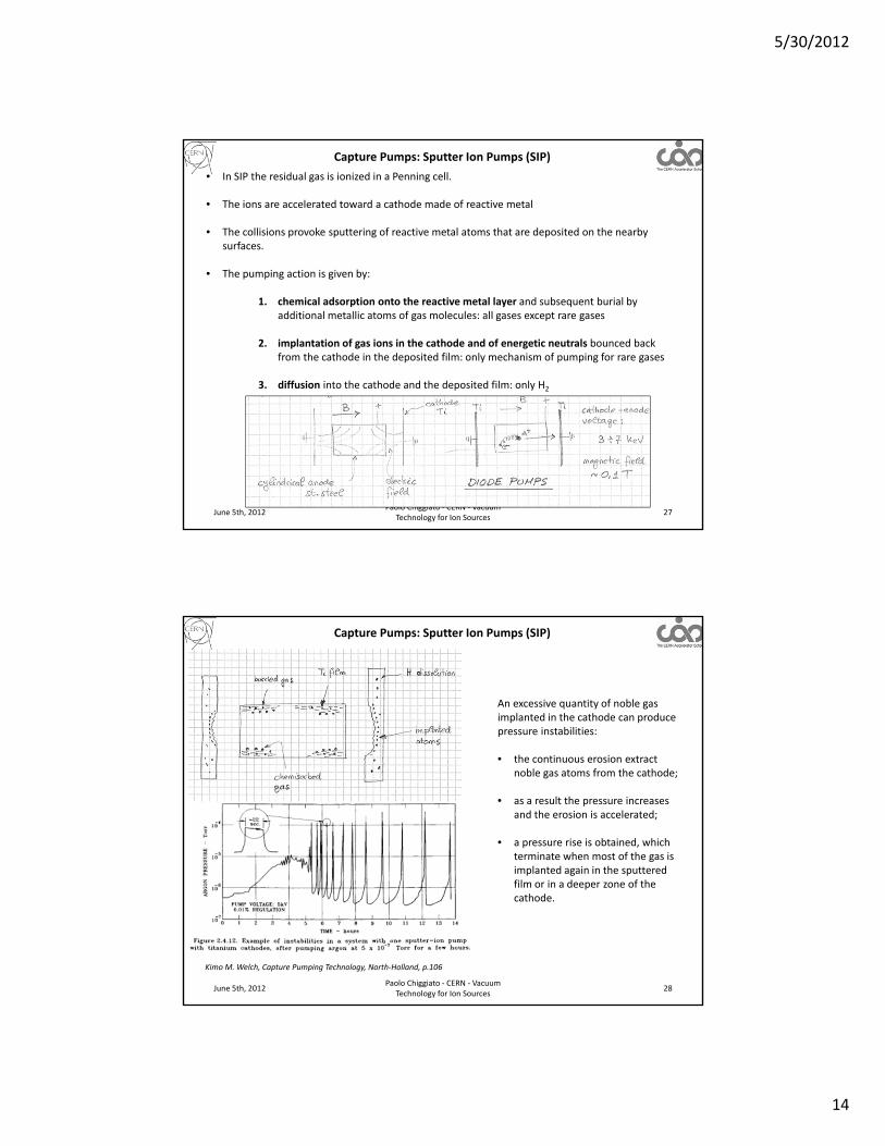
Capture Pumps: Sputter Ion Pumps (SIP)
• In SIP the residual gas is ionized in a Penning cell.
• The ions are accelerated toward a cathode made of reactive metal
• The collisions provoke sputtering of reactive metal atoms that are deposited on the nearby surfaces.
• The pumping action is given by:
1. chemical adsorption onto the reactive metal layer and subsequent burial by additional metallic atoms of gas molecules: all gases except rare gases
2. implantation of gas ions in the cathode and of energetic neutrals bounced back from the cathode in the deposited film: only mechanism of pumping for rare gases
3. diffusion into the cathode and the deposited film: only H2
June 5th, 2012Paolo Chiggiato ‐ CERN ‐ Vacuum
Technology for Ion Sources28
Capture Pumps: Sputter Ion Pumps (SIP)
An excessive quantity of noble gas implanted in the cathode can produce pressure instabilities:
• the continuous erosion extract noble gas atoms from the cathode;
• as a result the pressure increases and the erosion is accelerated;
• a pressure rise is obtained, which terminate when most of the gas is implanted again in the sputtered film or in a deeper zone of the cathode.
Kimo M. Welch, Capture Pumping Technology, North‐Holland, p.106

5/30/2012
15
June 5th, 2012Paolo Chiggiato ‐ CERN ‐ Vacuum
Technology for Ion Sources29
Capture Pumps: Sputter Ion Pumps (SIP)
To increase the pumping efficiency of noble gas, the rate of ions implantation in the cathode has to be reduced while increasing the rate of energetic neutrals impingement on the anode and their burial probability.
Two different approches:
1. Heavier atoms for the cathodeTa (181 amu) is used instead of Ti (48 amu). The ions, once neutralized, bounce back at higher energy and rate →these pumps are called ‘noble diode’
2. Different geometry of the Penning cell.a) Three electrodes are used: triode pumps. The cathodes consists of a series of small
platelets aligned along the cell axis.b) The collisions ion‐cathode are at glancing angle → higher sputtering rate of Ti atoms +
higher probability of neutralization + higher energy of bouncing + lower probability of implantation in the cathode.
June 5th, 2012Paolo Chiggiato ‐ CERN ‐ Vacuum
Technology for Ion Sources30
Capture Pumps: Sputter Ion Pumps (SIP)
An improved triode ion pump is the StarCell (Agilent Vacuum)
Kimo M. Welch, Capture Pumping Technology, North‐Holland, p.113

5/30/2012
16
June 5th, 2012Paolo Chiggiato ‐ CERN ‐ Vacuum
Technology for Ion Sources31
Capture Pumps: Sputter Ion Pumps (SIP)
Nominal pumping speed for N2:Varian starcell
DN S [ l s-1]
63 50
100 70/125
150 240/500
Pumping speed for SIP depends on the pressure at the pump inlet and the nature of the gas.
GAS DIODE PUMPS
TRIODPUMPS
AIR 1 1
N2 1 1
O2 1 1
H2 1.5‐2 1.5‐2
CO 0.9 0.9
CO2 0.9 0.9
H2O 0.8 0.8
CH4 0.6‐1 0.6‐1
Ar 0.03 0.25
He 0.1 0.3
Pumping speed normalized to air
Capture Pumps: Sputter Ion Pumps (SIP)
Courtesy o
f Agilen
t Vacuum
http
://www.ch
em.agilen
t.com/en
‐US/P
roducts/In
struments/va
cuum

5/30/2012
17
June 5th, 2012Paolo Chiggiato ‐ CERN ‐ Vacuum
Technology for Ion Sources33
Capture Pumps: Getter Pumps
The surface of getter materials reacts with gas molecules by forming stable chemical compounds.
This is possible only if the surface is clean, free of contamination and native oxide.
The clean metallic surface is obtained by:
1. Sublimating the reactive metal in situ→ Evaporable Getters, Sublimation Pumps
2. Dissolving the surface contamination into the bulk of the getter material by heating in situ (activation): Non‐Evaporable Getters NEG.
Getter surfaces are characterized by the sticking probability :
0 1
For =1, the pumping speed of the surface is equal to its maximum pumping speed.Getter materials do not pump rare gases and methane at room temperature.
June 5th, 2012Paolo Chiggiato ‐ CERN ‐ Vacuum
Technology for Ion Sources34
Capture Pumps: Sublimation Pumps
For particle accelerators Ti is the sublimated metal.
Ti alloy rods are heated up to 1500°C attaining a Ti vapour pressure of about 10‐3 mbar.
The sticking probabilities depend on the nature of the gas and the quantity of gas already pumped.
: 10 10: 5 10 1
The sticking probability is negligible:• For CO, one monolayer adsorbed• For of O2 several monolayer• For N2 fraction of monolayer
→ oneadditionalsublimationisneeded
Hydrogen diffuses in the Ti film→much higher capacity
Courtesy of Kurt J. Lesker Companyhttp://www.lesker.com/newweb/Vacuum_Pumps
A K Gupta and J H Leek, Vacuum, 25(1975)362
max

5/30/2012
18
June 5th, 2012Paolo Chiggiato ‐ CERN ‐ Vacuum
Technology for Ion Sources35
Capture Pumps: NEG Pumps
Heating in vacuumOxide layer dissolution-> activation
T = Ta
T = RT
Surface oxide Active surface
T = RT
No pumping Pumping
The dissolution of the oxide layer is possible only in metals having very high oxygen solubility limit, namely the elements of the 4th group: Ti, Zr and Hf.
June 5th, 2012Paolo Chiggiato ‐ CERN ‐ Vacuum
Technology for Ion Sources36
Capture Pumps: NEG Pumps
The activation temperature of the 4th group elements can be decreased by adding selected elements which increase oxygen diffusivity.
NEG materials are produced industrially by powder technology. Small grains are sintered to form pellets, discs or plates. The grains can also be pressed at room temperature on metallic ribbon.
A typical alloy produced by SAES Getter is St707:
ElementConcentration
[wt. %]Main role in the alloy
Zr 70 ‐ High O solubility limit. ‐ Chemical reactivity
V 24.6 ‐ Increases O diffusivity,‐ Chemical reactivity
Fe 5.4 ‐ Reduces pyrophoricity
Full pumping speed is obtained after heating at 400°C for 45’ or 300°C for 24h

5/30/2012
19
June 5th, 2012Paolo Chiggiato ‐ CERN ‐ Vacuum
Technology for Ion Sources37
Capture Pumps: NEG Pumps
Courtesy o
f SAES G
etters, www.sa
esgetters.co
m
The maximum H2 sorption capacity is limited by H2
embrittlement of the NEG elements.In general a safe limit is 20 Torr l/g is given by the supplier.
The stored H2 can be desorbed by heating and pumping with an auxiliary pump (for example a TMP).
June 5th, 2012Paolo Chiggiato ‐ CERN ‐ Vacuum
Technology for Ion Sources38
Capture Pumps: NEG Pumps
The high porosity of NEG materials allows pumping of relatively high quantities of gas without reactivation: for CO about 100 times higher than those for sublimation pumps per unit geometrical surface of active metal.
Courtesy of SAES Getters, www.saesgetters.com

5/30/2012
20
June 5th, 2012Paolo Chiggiato ‐ CERN ‐ Vacuum
Technology for Ion Sources39
Capture Pumps: Cryopumps
Cryopumps rely on three different pumping mechanisms:
1. Cryocondensation: is based on the mutual attraction of similar molecules at low temperature: a. the key property is the saturated vapour pressure, i.e. the pressure of the gas
phase in equilibrium with the condensate at a given temperature.b. Large quantity of gas can be cryocondensated (limited only by the thermal
properties of the condensate phase)c. The attainable pressure is limited by the saturated vapour pressure.
d) Only Ne, H2 and He have vapour pressures higher than 10‐11 Torr at 20 K.
e) The vapour pressure of H2 at 4.3 K is in the 10‐7
Torr range, at 1.9 lower than 10‐12 Torr.
June 5th, 2012Paolo Chiggiato ‐ CERN ‐ Vacuum
Technology for Ion Sources40
Capture Pumps: Cryopumps
2. Cryosorption: is based on the attraction between molecules and substrate. The van der Waals forces are much stronger than those between similar molecules:
a) Gas molecules are pumped at pressure much lower than the saturated vapourpressure providing the adsorbed quantity is lower than one monolayer.
a) Porous materials are used to increase the specific surface area; for charcoal about 1000 m2 per gram are normally achieved.
b) The important consequence is that significant quantities of H2 can be pumped at 20 K and He at 4.3 K.
c) Submonolayer quantities of all gases may be effectively cryosorbed at their own boiling temperature; for example at 77 K all gases except He, H2 and Ne.
3. Cryotrapping is understood as the inclusion of a low boiling point gas which is difficult to pump such as hydrogen, in the matrix of a gas having a higher boiling point and which can be pumped easily such as Ar, CH4 or CO2. At the same temperature the condensate mixture has a saturation vapor pressure which is by several orders of magnitude lower than the pure condensate of the gas with the lower boiling point.

5/30/2012
21
June 5th, 2012Paolo Chiggiato ‐ CERN ‐ Vacuum
Technology for Ion Sources41
Capture Pumps: Cryopumps
Modern cryopumps take advantages of each mechanisms.
1. The cryocondensation takes place on a cold surfaces, in general at 80K for H2O and 10 or 20 K for the other gases.
2. The cryosorption of H2, Ne and He is localised on a hidden surface where a porous material is fixed. This surface is kept away from the reach of the other molecules.
Helium is the working fluid of modern cryopumps.
June 5th, 2012Paolo Chiggiato ‐ CERN ‐ Vacuum
Technology for Ion Sources42
Courtesy of Oerlikon Leybold Vacuum www.oerlikon.com/leyboldvacuum
Cryopumps require periodic regeneration to evacuate the gas adsorbed or condensed.
To remove all captured gas, the pump is warmed at room temperature. The desorbed gas is removed by mechanical pumps (in general, for accelerators, mobile TMP). During regeneration, the rest of the system must be separated by a valve.

5/30/2012
22
June 5th, 2012Paolo Chiggiato ‐ CERN ‐ Vacuum
Technology for Ion Sources43
Comparison of Pumps
Advantages Disadvantages
TMP
‐ No memory effects‐ Constant pumping speed for pressures lower
than 10‐3 mbar‐ Pumping speed independent of total gas load‐ Starts working at high pressures (molecular
regime)
‐ Mechanical fragility‐ Risk of contamination from the backing pump‐ Need of venting anytime the pump is stopped ‐ Need of valve on the main flange‐ Intrinsic limitation in ultimate pressure of H2
SIP
‐ Clean pumping‐ No maintenance‐ No vibrations‐ Installation in any orientation‐ Relatively long lifetime‐ Relatively low cost‐ Limited but high H2 capacity
‐ Low capture probability‐ Gas Selectivity and limited capacity‐ Memory effects (in particular for rare gases)‐ Ignition in 10‐5 mbar range‐ Bulky‐ Difficult starting for old pumps‐ Production of charged particles in particular at
start‐up‐ Field emission problems for old pumps‐ Fringing magnetic field ‐ Safety issue: high voltage
June 5th, 2012Paolo Chiggiato ‐ CERN ‐ Vacuum
Technology for Ion Sources44
Advantages Disadvantages
SublimationPumps
‐ Clean vacuum‐ High pumping speed for reactive gases‐ With SIP, extremely low vacuum can be
achieve‐ Low cost‐ Electrical power only for sublimation; it works
in case of power cut‐ Limited maintenance (filament change)‐ No vibration
‐ Very limited capacity‐ Need frequent sublimations‐ Ti film peel‐off for high sublimation rates‐ Selective pumping (no pumping of rare gases
and methane)‐ Risk of leakage current in high voltage
insulators‐ Relatively low working pressure
NEG pumps ‐ Clean vacuum‐ High pumping speed for reactive gases‐ With SIP, extremely low vacuum can be
achieve‐ High gas capacity for porous NEG‐ Low cost‐ Electrical power only for activation; it works in
case of power cut‐ No maintenance‐ No vibration
‐ Selective pumping (no pumping of rare gases and methane)
‐ H2 embrittlement if regeneration is not applied
‐ Formation of dust particles is not excluded‐ Possible peel‐off of NEG deposited on
metallic ribbons.‐ Safety issue: pyrophoric, it burns when
heated in air at high temperature
Comparison of Pumps

5/30/2012
23
June 5th, 2012Paolo Chiggiato ‐ CERN ‐ Vacuum
Technology for Ion Sources45
Advantages Disadvantages
Cryopumps ‐ Very large pumping speed for all gases‐ Clean vacuum‐ High pumping capacity‐ Limited selectivity
‐ Cost and maintenance‐ Relatively large volume needed (including
refrigerator)‐ Gas release in case of power cut‐ Reduced pumping efficiency for H2 for high
quantity of gas adsorbed: regeneration needed
‐ Need of valve on the main flange
Comparison of Pumps
Conclusions
June 5th, 2012Paolo Chiggiato ‐ CERN ‐ Vacuum
Technology for Ion Sources46
Appendix 1Basic Notions : Gas Pressure
Definition of pressure:
Unit of measurement: → = → 10 1 → 1 1.013
Still used in vacuum technology: 1 1 ;1 760
Pa bar atm Torr
1 Pa 1 10‐5 9.87 10‐6 7.5 10‐3
1 bar 102 1 0.987 750.06
1 atm 1.013 105 1.013 1 760
1 Torr 133.32 1.33 10‐3 1.32 10‐3 1
Invacuumtechnology ∶
Conversion Table
5/30/2012
24
June 5th, 2012Paolo Chiggiato ‐ CERN ‐ Vacuum
Technology for Ion Sources47
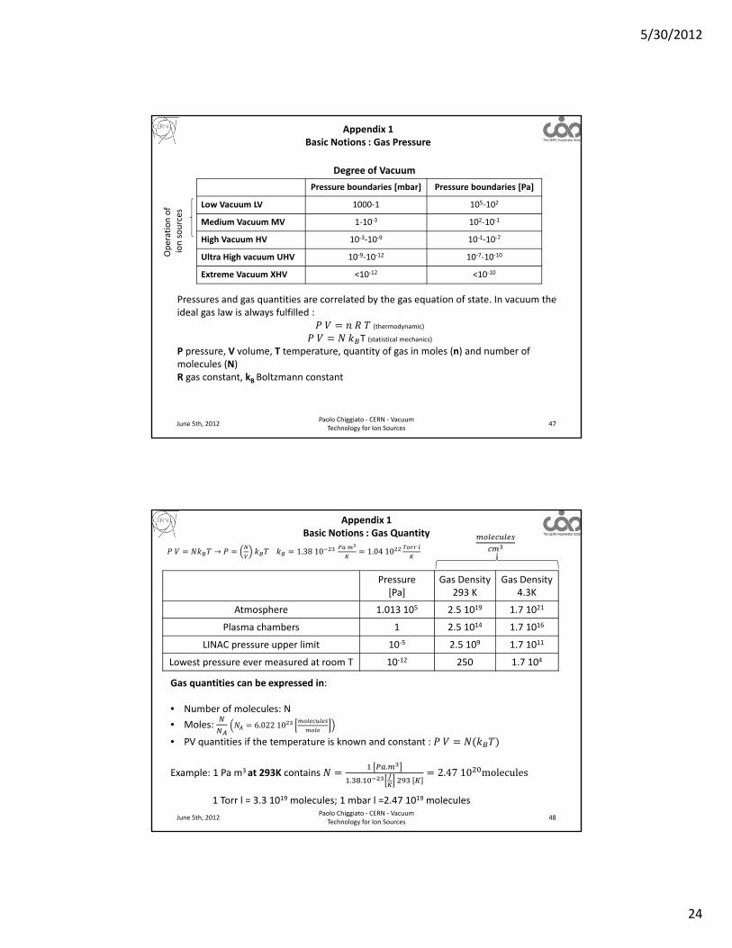
Pressure boundaries [mbar] Pressure boundaries [Pa]
Low Vacuum LV 1000‐1 105‐102
Medium Vacuum MV 1‐10‐3 102‐10‐1
High Vacuum HV 10‐3‐10‐9 10‐1‐10‐7
Ultra High vacuum UHV 10‐9‐10‐12 10‐7‐10‐10
Extreme Vacuum XHV <10‐12 <10‐10
Degree of VacuumOperation of
ion sources
Pressures and gas quantities are correlated by the gas equation of state. In vacuum the ideal gas law is always fulfilled :
(thermodynamic)
T (statistical mechanics)
P pressure, V volume, T temperature, quantity of gas in moles (n) and number of molecules (N)R gas constant, kBBoltzmann constant
Appendix 1Basic Notions : Gas Pressure
June 5th, 2012Paolo Chiggiato ‐ CERN ‐ Vacuum
Technology for Ion Sources48
→ 1.3810 1.0410
Pressure [Pa]
Gas Density 293 K
Gas Density 4.3K
Atmosphere 1.013 105 2.5 1019 1.7 1021
Plasma chambers 1 2.5 1014 1.7 1016
LINAC pressure upper limit 10‐5 2.5 109 1.7 1011
Lowest pressure ever measured at room T 10‐12 250 1.7 104
Gas quantities can be expressed in:
• Number of molecules: N
• Moles: 6.02210
• PV quantities if the temperature is known and constant :
Example: 1 Pa m3 at 293K contains .
. . 2.4710 molecules
1 Torr l = 3.3 1019 molecules; 1 mbar l =2.47 1019 molecules
Appendix 1Basic Notions : Gas Quantity

5/30/2012
25
June 5th, 2012Paolo Chiggiato ‐ CERN ‐ Vacuum
Technology for Ion Sources49
In the kinetic theory of gas the mean speed ofa molecule is the mathematical average of the speed distribution:
8
8
m is the molecular mass [Kg]M is the molecular weight [Kg]Courtesy of Wikipedia:
http://en.wikipedia.org/wiki/Maxwell%E2%80%93Boltzmann_distribution
Gas .
H2 1761 213
He 1244 151
CH4 622 75
N2 470 57
Ar 394 48
Appendix 1Basic Notions : Molecular Mean Speed
June 5th, 2012Paolo Chiggiato ‐ CERN ‐ Vacuum
Technology for Ion Sources50
φ 14
14
8
φ 2.63510
Gas Pressure [mbar]
Impingement rate
293 K [cm‐2s‐1]
H2
10‐3 1.1 1018
10‐8 1.1 1014
10‐14 1.1 108
N210‐3 2.9 1017
10‐8 2.9 1013
Ar10‐3 2.4 1017
10‐8 2.4 1013
Appendix 1Basic Notions : Impingement Rate with a Surface

5/30/2012
26
June 5th, 2012Paolo Chiggiato ‐ CERN ‐ Vacuum
Technology for Ion Sources51
The molecular collision rate in a gas is:
2
where is the collision cross section. For a single gas, in case of elastic collision of solid spheres:
→ 2 and is the molecular diameter.
The mean free path , i.e. the average distance travelled by a molecule between collisions, is given by:
1
2 2
Gas
H2 0.27
He 0.21
N2 0.43
O2 0.40
CO2 0.52
4.310
Appendix 1Basic Notions : Mean Free Path
June 5th, 2012Paolo Chiggiato ‐ CERN ‐ Vacuum
Technology for Ion Sources52
is the mean free path and D is a characteristic dimension of a vacuum system (p.ex. the diameter of a beam pipe).
Kn range Regime Description
Kn >0.5 Free molecular flow The gas dynamic is dominated by molecular collisions with the walls of the system
Kn <0.01 Continuous (viscous) flow The gas dynamic is dominated by intermolecular collisions
0.5<Kn <0.01 Transitional flow Transition between molecular and viscous flow
Appendix 1Basic Notions : Knudsen Number

5/30/2012
27
June 5th, 2012Paolo Chiggiato ‐ CERN ‐ Vacuum
Technology for Ion Sources53
Moon‐Earth distance
Earth diameter
Typical dimensionof standard vacuum
system
Paris‐New Yorkdistance
Kn≈1
Appendix 1Basic Notions : Knudsen Number
June 5th, 2012Paolo Chiggiato ‐ CERN ‐ Vacuum
Technology for Ion Sources54
Appendix 1Basic Notions : Knudsen Number
5/30/2012
28
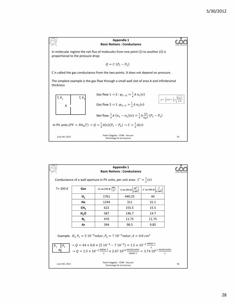
In molecular regime the net flux of molecules from one point (1) to another (2) is proportional to the pressure drop:
C is called the gas conductance from the two points. It does not depend on pressure.
The simplest example is the gas flow through a small wall slot of area A and infinitesimal thickness
June 5th, 2012Paolo Chiggiato ‐ CERN ‐ Vacuum
Technology for Ion Sources55
T, P1 T, P2Gas flow 1 ‐> 2 : →
Gas flow 2 ‐> 1 : →
φ 14
14
8
A
Net flow:
In PV units ( → →
Appendix 1Basic Notions : Conductance
June 5th, 2012Paolo Chiggiato ‐ CERN ‐ Vacuum
Technology for Ion Sources56
Conductance of a wall aperture in PV units, per unit area:
T= 293 K Gas
H2 1761 440.25 44
He 1244 311 31.1
CH4 622 155.5 15.5
H2O 587 146.7 14.7
N2 470 11.75 11.75
Ar 394 98.5 9.85
Example: 510 , 710 , 0.8
→ 44 0.8 510 710 1.5 10
→ 1.5 10
2.4710
3.7410
P1 P2A
Appendix 1Basic Notions : Conductance

5/30/2012
29
June 5th, 2012Paolo Chiggiato ‐ CERN ‐ Vacuum
Technology for Ion Sources57
For more complicated gas flow restrictions, the transmission probability is introduced.
P1 P2A1 A2
Vessel 1 Vessel 2 Gas flow 1 ‐> 2 : → →
Gas flow 2 ‐> 1 : → →
In absence of net flow: → →and P1=P2→ → →
14
→14
→14
→
In PV units:14
→ C
→
Appendix 1Basic Notions : Conductance
June 5th, 2012Paolo Chiggiato ‐ CERN ‐ Vacuum
Technology for Ion Sources58
The molecular transmission probabilities:
• depend only on the geometry of the vacuum system;• can be calculated only for simple geometry;• nowadays are accurately obtained by Monte Carlo methods.
Example:
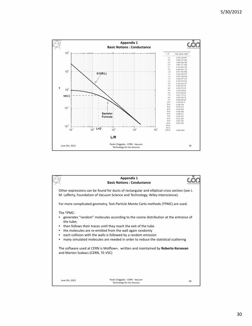
• Tubes of uniform circular cross section ( length, R radius); Santeler formula (max error 0.7%):
→ →1
138 1
1
3 1 7For long tubes ( ≫ 1):
For N2 and ≫ 1 → 11.75 12.3
Appendix 1Basic Notions : Conductance
5/30/2012
30
June 5th, 2012Paolo Chiggiato ‐ CERN ‐ Vacuum
Technology for Ion Sources59
Appendix 1Basic Notions : Conductance
June 5th, 2012 Paolo Chiggiato ‐ CERN ‐ Vacuum Technology for Ion Sources
60
Other expressions can be found for ducts of rectangular and elliptical cross section (see J. M. Lafferty, Foundation of Vacuum Science and Technology, Wiley Interscience).
For more complicated geometry, Test‐Particle Monte Carlo methods (TPMC) are used.
The TPMC:• generates “random” molecules according to the cosine distribution at the entrance of
the tube;• then follows their traces until they reach the exit of the tube• the molecules are re‐emitted from the wall again randomly• each collision with the walls is followed by a random emission • many simulated molecules are needed in order to reduce the statistical scattering
The software used at CERN is Molflow+, written and maintained by Roberto Kersevan and Marton Szakacs (CERN, TE‐VSC)
Appendix 1Basic Notions : Conductance

5/30/2012
31
June 5th, 2012Paolo Chiggiato ‐ CERN ‐ Vacuum
Technology for Ion Sources61
The full simulation of the MedAustron facility.
Ch. Yin Vallgren et al., CERN, ATS/Note/2012/043 TECH
Appendix 2: Additional Examples of Electrical Analogy
June 5th, 2012Paolo Chiggiato ‐ CERN ‐ Vacuum
Technology for Ion Sources62
Equivalent electrical network for sector 560.
Lay-out of the SPS vacuum sector 560.
Evaluation of pressure profile during pump‐down in the SPS ring J. A. Ferreira Somoza, CERN, TE‐VSC internal note, 05‐2012
Appendix 2: Additional Examples of Electrical Analogy
5/30/2012
32
June 5th, 2012Paolo Chiggiato ‐ CERN ‐ Vacuum
Technology for Ion Sources63
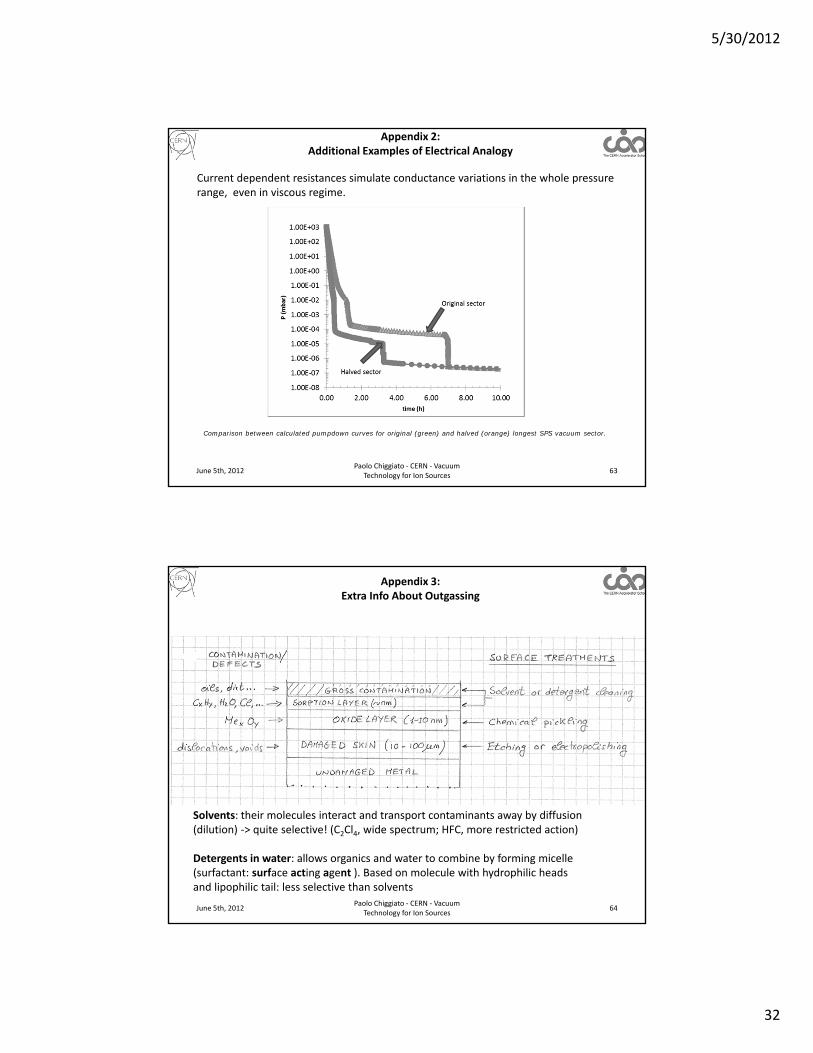
Comparison between calculated pumpdown curves for original (green) and halved (orange) longest SPS vacuum sector.
Current dependent resistances simulate conductance variations in the whole pressure range, even in viscous regime.
Appendix 2: Additional Examples of Electrical Analogy
June 5th, 2012Paolo Chiggiato ‐ CERN ‐ Vacuum
Technology for Ion Sources64
Solvents: their molecules interact and transport contaminants away by diffusion (dilution) ‐> quite selective! (C2Cl4, wide spectrum; HFC, more restricted action)
Detergents in water: allows organics and water to combine by forming micelle (surfactant: surface acting agent ). Based on molecule with hydrophilic heads and lipophilic tail: less selective than solvents
Appendix 3: Extra Info About Outgassing

5/30/2012
33
June 5th, 2012Paolo Chiggiato ‐ CERN ‐ Vacuum
Technology for Ion Sources65
H.F. Dylla, D. M. Manos, P.H. LaMarche Jr. Journal of Vacuum Science and Tech. A, 11(1993)2623
Outgassing rate of water vapour for unbaked metals
Appendix 3: Extra Info About Outgassing
June 5th, 2012Paolo Chiggiato ‐ CERN ‐ Vacuum
Technology for Ion Sources66
R. N. Peacock, J. Vac. Sci. Technol., 17(1), p.330, 1980
baked Viton
unbaked Viton
10‐10
10‐6
Outgassing rate of water vapour for polymers
Appendix 3: Extra Info About Outgassing

5/30/2012
34
June 5th, 2012 Paolo Chiggiato ‐ CERN ‐ Vacuum Technology for Ion Sources
67
Pressure profiles with distributed outgassing can be calculated analytically (for simple geometry), by electrical analogy or by Monte Carlo simulation.
P(0)
S
P(x)
x
x
L
Distributed outgassing
x x+x
P(0)
S
P(x)
x
x
L
Distributed outgassing
P(0)
S
PMAX
Appendix 3: Extra Info About Outgassing
June 5th, 2012Paolo Chiggiato ‐ CERN ‐ Vacuum
Technology for Ion Sources68
Hydrogen pumping by SIP• H2 is mainly pumped by diffusion into the cathode.• To be adsorbed, H2 must be dissociated. Only 2.5% of the ions created in a low‐pressure
H2 Penning discharge are H+ ions.• The dissociation is possible only on atomically clean Ti.• H2 + ions have poor sputtering yield: 0.01 at 7 KeV on Ti.
• When H2 is the main gas, it takes a long time to clean the cathode surface by sputtering.• As a consequence, at the beginning of the operation the pumping speed for H2 is lower
than the nominal and increases gradually with time.• The simultaneous pumping of another gas has strong effects on H2 pumping speed.
• Higher sputtering yield→faster cleaning→ higher pumping speed• Contaminating of the Ti surface→ lower pumping speed• Desorption of implanted H ions→ lower pumping speed
• When the concentration of H2 is higher than the solubility limit in Ti, hydride precipitates are formed→ Ti expansion and hydrogen embrittlement→ short circuits and cathode brittleness (for 500 l/s pumps: typical value are 10000 Torr l of H2)
Appendix 4: Extra Info about SIP

5/30/2012
35
June 5th, 2012Paolo Chiggiato ‐ CERN ‐ Vacuum
Technology for Ion Sources69
High Pressure Operation• High pressure (>10‐5 mbar) operation can generate thermal run‐away. It is frequently
noticeable during the pumping of H2 or after the absorption of high quantity of H2 (for example due to pumping of H2O).
• The Penning discharge heats the cathode and provokes gas desorption, which enhance the discharge. This positive feedback mechanism can melt locally the cathode.
• The total electrical power given to the pump has to be limited at high pressure.
Pressure measurement by ion pumps• The discharge current of the penning cells can be used for pressure measurement.• In the low pressure range, the current measurement is limited by field emission
(leakage current).• By reducing the applied voltage in the lower pressure range, the pressure measurement
is possible down to 10‐10 mbar. Courtesy o
f Agilen
t Vacuum
Appendix 4: Extra Info about SIP
June 5th, 2012Paolo Chiggiato ‐ CERN ‐ Vacuum
Technology for Ion Sources70
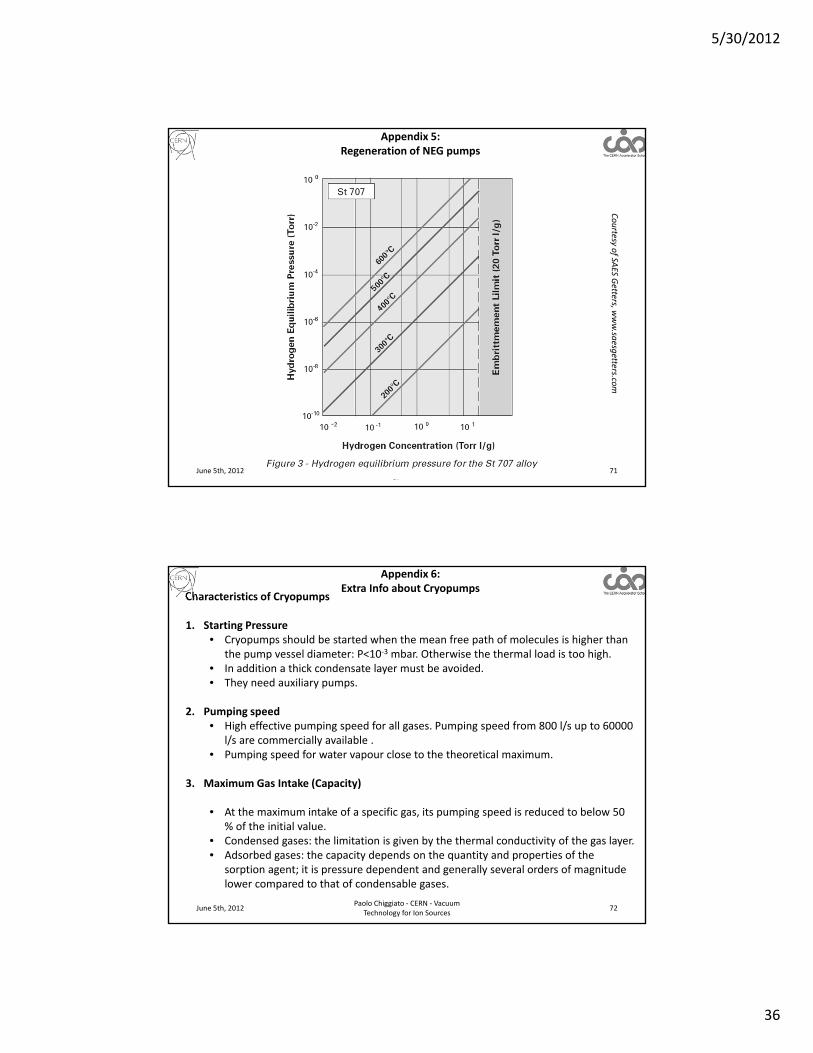
The maximum H2 sorption capacity is limited by H2 embrittlement of the NEG elements.In general a safe limit is 20 Torr l/g is given by the supplier.
The stored H2 may be desorbed by heating and pumping with an auxiliary pump (for example a TMP).
The time tR needed to regenerate a NEG pump is given by:
Where:qf and qi are the final and initial concentrations in Torr l/gSaux is the pumping speed of the TMPM the mass of the NEG in gA and B typical values of the NEG material For St707: A=4.8, B= ‐6116
The pressure during the regeneration heating is given by: 2q is the actual hydrogen concentration
Appendix 5: Regeneration of NEG pumps
5/30/2012
36
June 5th, 2012Paolo Chiggiato ‐ CERN ‐ Vacuum
Technology for Ion Sources71
Courtesy o
f SAES G
etters, www.sa
esgetters.co
m
Appendix 5: Regeneration of NEG pumps
June 5th, 2012Paolo Chiggiato ‐ CERN ‐ Vacuum
Technology for Ion Sources72
Characteristics of Cryopumps
1. Starting Pressure• Cryopumps should be started when the mean free path of molecules is higher than
the pump vessel diameter: P<10‐3 mbar. Otherwise the thermal load is too high.• In addition a thick condensate layer must be avoided.• They need auxiliary pumps.
2. Pumping speed• High effective pumping speed for all gases. Pumping speed from 800 l/s up to 60000
l/s are commercially available . • Pumping speed for water vapour close to the theoretical maximum.
3. Maximum Gas Intake (Capacity)
• At the maximum intake of a specific gas, its pumping speed is reduced to below 50 % of the initial value.
• Condensed gases: the limitation is given by the thermal conductivity of the gas layer.• Adsorbed gases: the capacity depends on the quantity and properties of the
sorption agent; it is pressure dependent and generally several orders of magnitude lower compared to that of condensable gases.
Appendix 6: Extra Info about Cryopumps
5/30/2012
37
June 5th, 2012Paolo Chiggiato ‐ CERN ‐ Vacuum
Technology for Ion Sources73
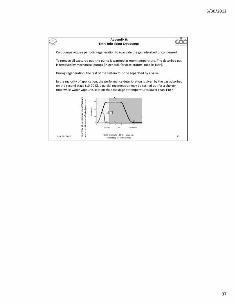
Cryopumps require periodic regeneration to evacuate the gas adsorbed or condensed.
To remove all captured gas, the pump is warmed at room temperature. The desorbed gas is removed by mechanical pumps (in general, for accelerators, mobile TMP).
During regeneration, the rest of the system must be separated by a valve.
In the majority of application, the performance deterioration is given by the gas adsorbed on the second stage (10‐20 K), a partial regeneration may be carried out for a shorter time while water vapour is kept on the first stage at temperatures lower than 140 K.
Courtesy of OerlikonLeyboldVacuum
www.oerlikon.com/leyboldvacuum
Appendix 6: Extra Info about Cryopumps