
Vacuum Pad for Circuit Board and Semiconductor Vacuum Pad Oval...
52
622 VACUUM PAD Soft Series Soft Bellows Series Skidproof Series Ultrathin Series Flat Series Long Stroke Series Vacuum Cylinder Air Pincette Mark-free Series Oval Series http://en.pisco.co.jp Vacuum Pad for Circuit Board and Semiconductor Vacuum Pad Oval Series ■ Suitable for long work-piece like Circuit board and Semiconductor. ■ Various selections of pad size, pad material and holder type. Circuit board and Semiconductor ■ Downsized holders (A, B, C and D type) are available for space-saving. No need to detach a holder when replacing vacuum pad. Optional selection of Fall prevention valve and Vacuum Filter. ■Pad size: 13 sizes ■Pad material:7types ➡ 9 types ■Holder type: 7 types (Standard), 4 types (Small) Variety of selections in pad holder for “Copper alloy free” and against “low ozone concentration” . No copper based metal parts, HNBR, and FKM are adopted for seal rubber. Newly added pad sizes and pad materials, suitable for smaller work-pieces and various installation environment. Newly available size : 2 x 4, 3.5 x 7mm Newly available material: Urethane rubber, Fluoro rubber, Conductive Silicone rubber, Conductive NBR (low resistance type), HNBR and EPDM.
Transcript of Vacuum Pad for Circuit Board and Semiconductor Vacuum Pad Oval...
622
VACUUM
PAD
SoftSeries
Soft BellowsSeries
SkidproofSeries
UltrathinSeries
FlatSeries
Long StrokeSeries
VacuumCylinder
AirPincette
Mark-freeSeries
OvalSeries
http://en.pisco.co.jp
Vacuum Pad for Circuit Board and SemiconductorVacuum Pad Oval Series
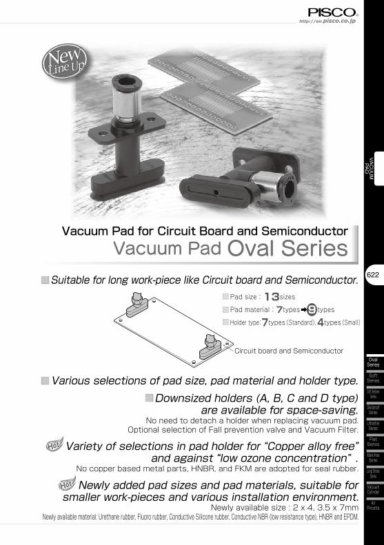
■ Suitable for long work-piece like Circuit board and Semiconductor.
■ Various selections of pad size, pad material and holder type.
Circuit board and Semiconductor
■ Downsized holders (A, B, C and D type) are available for space-saving.
No need to detach a holder when replacing vacuum pad. Optional selection of Fall prevention valve and Vacuum Filter.
■Pad size:13sizes
■Pad material:7types➡9 types
■Holder type:7types(Standard),4types(Small)
Variety of selections in pad holder for “Copper alloy free” and against “low ozone concentration” .
No copper based metal parts, HNBR, and FKM are adopted for seal rubber.
Newly added pad sizes and pad materials, suitable for smaller work-pieces and various installation environment.
Newly available size : 2 x 4, 3.5 x 7mmNewly available material: Urethane rubber, Fluoro rubber, Conductive Silicone rubber, Conductive NBR (low resistance type), HNBR and EPDM.
623
Vacuum Pad SeriesVacuum Pad Oval Series
VACUUM
PAD
OvalSeries
Multi-BellowsSeries
SpongeSeries
StandardSeries
BellowsSeries
VP 5×30 E
②. Pad size
A
①. Holder type
③. Pad type
6JN
B
A
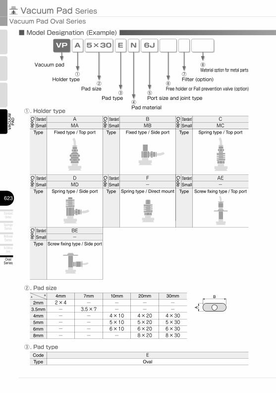
■ Model Designation (Example)
②Pad size
③Pad type
⑥Free holder or Fall prevention valve (option)
Vacuum pad
①Holder type
⑤Port size and joint type
④Pad material
⑦Filter (option)
⑧Material option for metal parts
A B
2mm3.5mm4mm5mm6mm8mm
10mm
−−
4×105×106×10−
7mm
−3.5×7−−−−
4mm
2×4−−−−−
AMA
Fixed type / Top port
BMB
Fixed type / Side port
CMC
Spring type / Top port
EOval
DMD
Spring type / Side port
F-
Spring type / Direct mount
20mm
−−
4×205×206×208×20
30mm
−−
4×305×306×308×30
AE-
Screw fixing type / Top port
BE-
Screw fixing type / Side portC
ode
Type
StandardSmall
Code
Type
StandardSmall
Code
Type
StandardSmall
Code
Type
StandardSmall
Code
Type
StandardSmall
Code
Type
StandardSmall
Code
Type
StandardSmall
CodeType
624
VACUUM
PAD
SoftSeries
Soft BellowsSeries
SkidproofSeries
UltrathinSeries
FlatSeries
Long StrokeSeries
VacuumCylinder
AirPincette
Mark-freeSeries
OvalSeries
http://en.pisco.co.jp
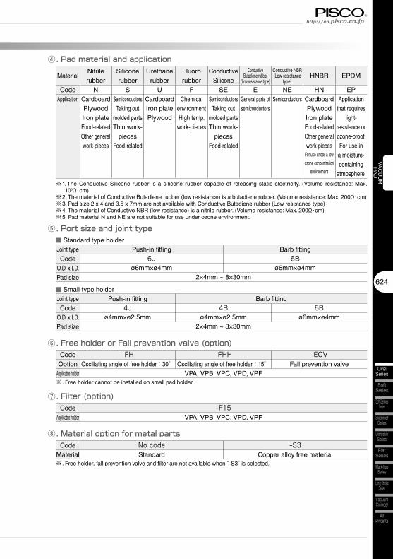
⑥. Free holder or Fall prevention valve (option)
⑤. Port size and joint type
④. Pad material and application
⑦. Filter (option)
MaterialNitrile rubber
Silicone rubber
Urethane rubber
Fluoro rubber
Conductive Silicone
Conductive Butadiene rubber
(Low resistance type)
Conductive NBR(Low resistance
type)HNBR EPDM
Code N S U F SE E NE HN EPApplication Cardboard
PlywoodIron plateFood-relatedOther general work-pieces
SemiconductorsTaking out
molded partsThin work-
piecesFood-related
CardboardIron platePlywood
Chemical environmentHigh temp.
work-pieces
SemiconductorsTaking out
molded partsThin work-
piecesFood-related
General parts of semiconductors
Semiconductors CardboardPlywoodIron plateFood-relatedOther general work-pieces
For use under a low
ozone concentration
environment
Application that requires
light-resistance or ozone-proof.For use in
a moisture-containing
atmosphere.
-FHOscillating angle of free holder:30°
-FHHOscillating angle of free holder:15°
Push-in fitting6J
ø6mm×ø4mm
Barb fitting6B
ø6mm×ø4mm2×4mm ~ 8×30mm
※1. The Conductive Silicone rubber is a silicone rubber capable of releasing static electricity. (Volume resistance: Max. 105Ω・cm)
※2. The material of Conductive Butadiene rubber (low resistance) is a butadiene rubber. (Volume resistance: Max. 200Ω・cm)※3. Pad size 2 x 4 and 3.5 x 7mm are not available with Conductive Butadiene rubber (Low resistance type)※4. The material of Conductive NBR (low resistance) is a nitrile rubber. (Volume resistance: Max. 200Ω・cm)※5. Pad material N and NE are not suitable for use under ozone environment.
-F15VPA, VPB, VPC, VPD, VPF
VPA, VPB, VPC, VPD, VPF
■ Standard type holder
Push-in fitting4J
ø4mm×ø2.5mm
Barb fitting
2×4mm ~ 8×30mm
■ Small type holder
6Bø6mm×ø4mm
4Bø4mm×ø2.5mm
-ECVFall prevention valve
⑧. Material option for metal partsCode
MaterialNo code -S3
※ . Free holder, fall prevention valve and filter are not available when “-S3” is selected.
※ . Free holder cannot be installed on small pad holder.
Standard Copper alloy free material
Joint typeCode
O.D. x I.D.Pad size
Joint typeCode
O.D. x I.D.Pad size
CodeOption
Applicable holder
CodeApplicable holder
625
Vacuum Pad SeriesVacuum Pad Oval Series
VACUUM
PAD
OvalSeries
Multi-BellowsSeries
SpongeSeries
StandardSeries
BellowsSeries
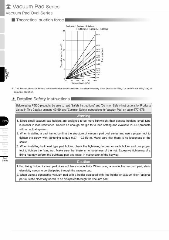
■ Theoretical suction force
0
15
10
5
0
25
20
20 40 60 80 100
8×30
6×30
5×30,8×20
4×306×20
5×20
4×20
6×10
Vacuum level(–kPa)
The
oret
ical
suc
tion
forc
e(N)
Pad
siz
e(m
m)
4×103.5×7
2×4
Pad size:2×4mm, 3.5×7mm,□×10mm, □×20mm, □×30mm
5×10
Detailed Safety InstructionsBefore using PISCO products, be sure to read “Safety Instructions” and “Common Safety Instructions for Products Listed in This Catalog on page 43-49, and “Common Safety Instructions for Vacuum Pad” on page 477-478.
Warning
Caution1. Pad fixing holder for oval pad does not have conductivity. When using a conductive vacuum pad, static
electricity needs to be dissipated through the vacuum pad.
2. When using a conductive vacuum pad with a holder equipped with free holder or vacuum filter (optional
parts), static electricity needs to be dissipated through the vacuum pad.
1. Since small vacuum pad holders are designed to be more lightweight than general holders, small type
is inferior in load resistance. Secure an enough margin for a load setting and evaluate PISCO products
with an actual system.
2. When installing a pad frame, confirm the structure of vacuum pad oval series and use a proper tool to
tighten the screw with tightening torque 0.27 ~ 0.33N・m. Make sure that there is no looseness of the
screw.
3. When installing bulkhead type pad holder, check the tightening torque for each holder and use proper
tool to tighten the fixing nut. Make sure that there is no looseness of the nut. Excessive tightening of a
fixing nut may deform the bulkhead part and result in malfunction of the keyway.
※ . The theoretical suction force is calculated under a static condition. Consider the safety factor (Horizontal lifting: 1/4 and Vertical lifting: 1/8) for
an actual operation.
626
VACUUM
PAD
SoftSeries
Soft BellowsSeries
SkidproofSeries
UltrathinSeries
FlatSeries
Long StrokeSeries
VacuumCylinder
AirPincette
Mark-freeSeries
OvalSeries
http://en.pisco.co.jp
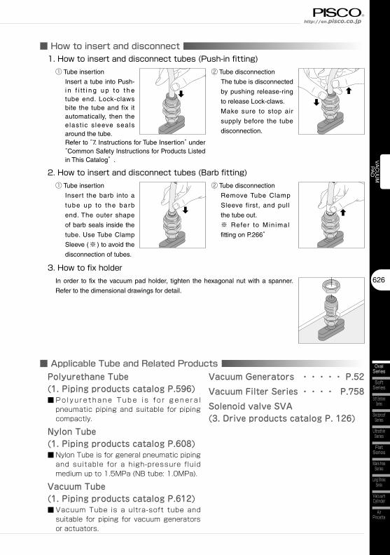
■ How to insert and disconnect
■ Applicable Tube and Related Products
1. How to insert and disconnect tubes (Push-in fitting)① Tube insertion
Insert a tube into Push-i n f i t t i n g u p to t h e tube end. Lock-claws bite the tube and fix it automatically, then the e last ic s leeve seals around the tube.Refer to “7. Instructions for Tube Insertion” under “Common Safety Instructions for Products Listed in This Catalog” .
② Tube disconnection
The tube is disconnected
by pushing release-ring
to release Lock-claws.
Make sure to stop air
supply before the tube
disconnection.
3. How to fix holderIn order to fix the vacuum pad holder, tighten the hexagonal nut with a spanner.
Refer to the dimensional drawings for detail.
2. How to insert and disconnect tubes (Barb fitting)① Tube insertion
Insert the barb into a
tube up to the barb
end. The outer shape
of barb seals inside the
tube. Use Tube Clamp
Sleeve (※ ) to avoid the
disconnection of tubes.
② Tube disconnection
Remove Tube Clamp
Sleeve first, and pull
the tube out.
※ Refer to Min imal
fitting on P.266”
Polyurethane Tube(1. Piping products catalog P.596)■ P o l y u r e t h a n e T u b e i s f o r g e n e r a l
pneumatic piping and suitable for piping compactly.
Nylon Tube(1. Piping products catalog P.608)■ Nylon Tube is for general pneumatic piping
and suitable for a high-pressure fluid medium up to 1.5MPa (NB tube: 1.0MPa).
Vacuum Tube(1. Piping products catalog P.612)■ Vacuum Tube is a ultra-soft tube and
suitable for piping for vacuum generators or actuators.
Vacuum Generators ・・・・・ P.52
Vacuum Filter Series ・・・・ P.758
Solenoid valve SVA(3. Drive products catalog P. 126)
627
Vacuum Pad SeriesVacuum Pad Oval Series
VACUUM
PAD
OvalSeries
Multi-BellowsSeries
SpongeSeries
StandardSeries
BellowsSeries
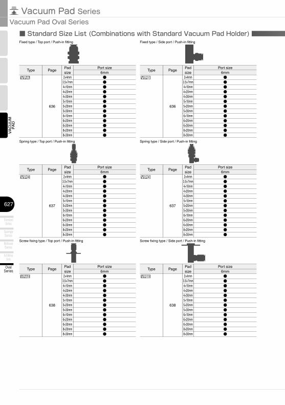
■ Standard Size List (Combinations with Standard Vacuum Pad Holder)
Type PagePad size
Port size6mm
VPA
636
2×4mm3.5×7mm4×10mm4×20mm4×30mm5×10mm5×20mm5×30mm6×10mm6×20mm6×30mm8×20mm8×30mm
●●●●●●●●●●●●●
Fixed type / Top port / Push-in fitting Fixed type / Side port / Push-in fitting
VPB
VPC
Spring type / Top port / Push-in fitting Spring type / Side port / Push-in fitting
VPD
Type PagePad size
Port size6mm
636
2×4mm3.5×7mm4×10mm4×20mm4×30mm5×10mm5×20mm5×30mm6×10mm6×20mm6×30mm8×20mm8×30mm
●●●●●●●●●●●●●
Type PagePad size
Port size6mm
637
2×4mm3.5×7mm4×10mm4×20mm4×30mm5×10mm5×20mm5×30mm6×10mm6×20mm6×30mm8×20mm8×30mm
●●●●●●●●●●●●●
Type PagePad size
Port size6mm
637
2×4mm3.5×7mm4×10mm4×20mm4×30mm5×10mm5×20mm5×30mm6×10mm6×20mm6×30mm8×20mm8×30mm
●●●●●●●●●●●●●
Type PagePad size
Port size6mm
VPAE
638
2×4mm3.5×7mm4×10mm4×20mm4×30mm5×10mm5×20mm5×30mm6×10mm6×20mm6×30mm8×20mm8×30mm
●●●●●●●●●●●●●
Screw fixing type / Top port / Push-in fitting Screw fixing type / Side port / Push-in fitting
VPBE
Type PagePad size
Port size6mm
638
2×4mm3.5×7mm4×10mm4×20mm4×30mm5×10mm5×20mm5×30mm6×10mm6×20mm6×30mm8×20mm8×30mm
●●●●●●●●●●●●●
628
VACUUM
PAD
SoftSeries
Soft BellowsSeries
SkidproofSeries
UltrathinSeries
FlatSeries
Long StrokeSeries
VacuumCylinder
AirPincette
Mark-freeSeries
OvalSeries
http://en.pisco.co.jp
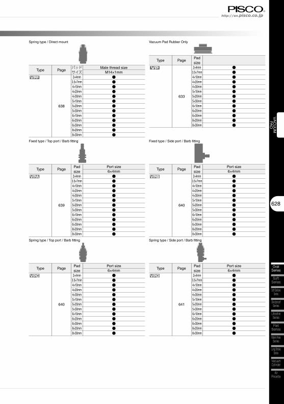
Spring type / Direct mount
VPF
VP
Vacuum Pad Rubber Only
Type Pageパッドサイズ
Male thread sizeM14×1mm
638
2×4mm3.5×7mm4×10mm4×20mm4×30mm5×10mm5×20mm5×30mm6×10mm6×20mm6×30mm8×20mm8×30mm
●●●●●●●●●●●●●
Type PagePad size
633
2×4mm3.5×7mm4×10mm4×20mm4×30mm5×10mm5×20mm5×30mm6×10mm6×20mm6×30mm8×20mm8×30mm
●●●●●●●●●●●●●
VPA
Fixed type / Top port / Barb fitting Fixed type / Side port / Barb fitting
VPB
VPC
Spring type / Top port / Barb fitting Spring type / Side port / Barb fitting
VPD
Type PagePad size
Port size6×4mm
639
2×4mm3.5×7mm4×10mm4×20mm4×30mm5×10mm5×20mm5×30mm6×10mm6×20mm6×30mm8×20mm8×30mm
●●●●●●●●●●●●●
Type PagePad size
Port size6×4mm
640
2×4mm3.5×7mm4×10mm4×20mm4×30mm5×10mm5×20mm5×30mm6×10mm6×20mm6×30mm8×20mm8×30mm
●●●●●●●●●●●●●
Type PagePad size
Port size6×4mm
640
2×4mm3.5×7mm4×10mm4×20mm4×30mm5×10mm5×20mm5×30mm6×10mm6×20mm6×30mm8×20mm8×30mm
●●●●●●●●●●●●●
Type PagePad size
Port size6×4mm
641
2×4mm3.5×7mm4×10mm4×20mm4×30mm5×10mm5×20mm5×30mm6×10mm6×20mm6×30mm8×20mm8×30mm
●●●●●●●●●●●●●
629
Vacuum Pad SeriesVacuum Pad Oval Series
VACUUM
PAD
OvalSeries
Multi-BellowsSeries
SpongeSeries
StandardSeries
BellowsSeries
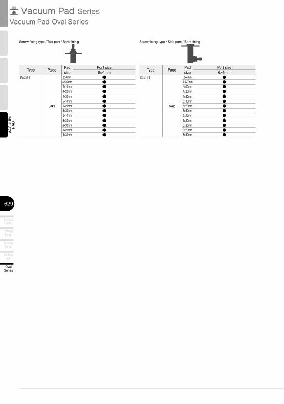
VPAE
Screw fixing type / Top port / Barb fitting Screw fixing type / Side port / Barb fitting
VPBE
Type PagePad size
Port size6×4mm
641
2×4mm3.5×7mm4×10mm4×20mm4×30mm5×10mm5×20mm5×30mm6×10mm6×20mm6×30mm8×20mm8×30mm
●●●●●●●●●●●●●
Type PagePad size
Port size6×4mm
642
2×4mm3.5×7mm4×10mm4×20mm4×30mm5×10mm5×20mm5×30mm6×10mm6×20mm6×30mm8×20mm8×30mm
●●●●●●●●●●●●●
630
VACUUM
PAD
SoftSeries
Soft BellowsSeries
SkidproofSeries
UltrathinSeries
FlatSeries
Long StrokeSeries
VacuumCylinder
AirPincette
Mark-freeSeries
OvalSeries
http://en.pisco.co.jp
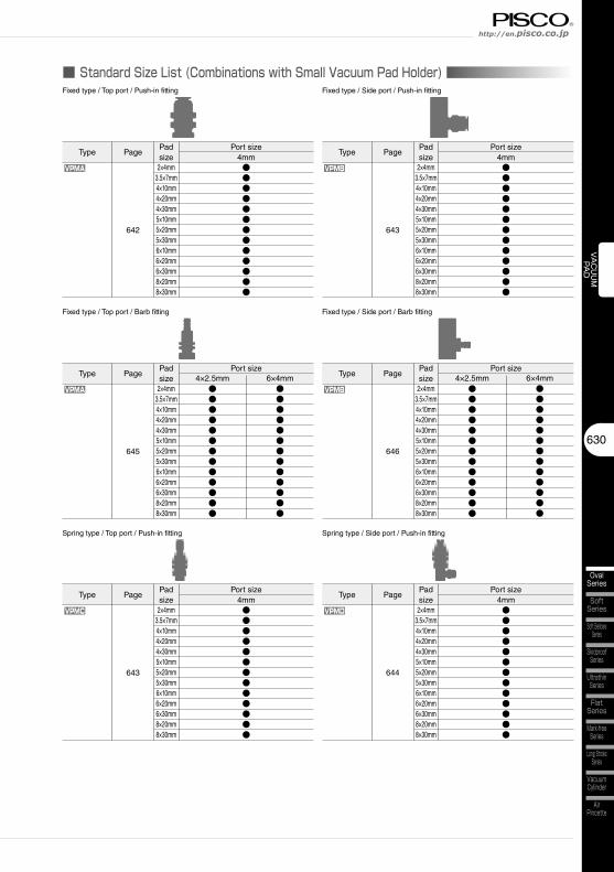
■ Standard Size List (Combinations with Small Vacuum Pad Holder)
Type PagePad size
Port size4mm
VPMA
642
2×4mm3.5×7mm4×10mm4×20mm4×30mm5×10mm5×20mm5×30mm6×10mm6×20mm6×30mm8×20mm8×30mm
●●●●●●●●●●●●●
Fixed type / Top port / Push-in fitting Fixed type / Side port / Push-in fitting
VPMB
Type PagePad size
Port size4mm
643
2×4mm3.5×7mm4×10mm4×20mm4×30mm5×10mm5×20mm5×30mm6×10mm6×20mm6×30mm8×20mm8×30mm
●●●●●●●●●●●●●
VPMA
Fixed type / Top port / Barb fitting Fixed type / Side port / Barb fitting
VPMB
Type PagePad size
Port size4×2.5mm
645
2×4mm3.5×7mm4×10mm4×20mm4×30mm5×10mm5×20mm5×30mm6×10mm6×20mm6×30mm8×20mm8×30mm
●●●●●●●●●●●●●
Type PagePad size
Port size4×2.5mm
646
2×4mm3.5×7mm4×10mm4×20mm4×30mm5×10mm5×20mm5×30mm6×10mm6×20mm6×30mm8×20mm8×30mm
●●●●●●●●●●●●●
6×4mm●●●●●●●●●●●●●
6×4mm●●●●●●●●●●●●●
VPMC
Spring type / Top port / Push-in fitting Spring type / Side port / Push-in fitting
VPMD
Type PagePad size
Port size4mm
643
2×4mm3.5×7mm4×10mm4×20mm4×30mm5×10mm5×20mm5×30mm6×10mm6×20mm6×30mm8×20mm8×30mm
●●●●●●●●●●●●●
Type PagePad size
Port size4mm
644
2×4mm3.5×7mm4×10mm4×20mm4×30mm5×10mm5×20mm5×30mm6×10mm6×20mm6×30mm8×20mm8×30mm
●●●●●●●●●●●●●
631
Vacuum Pad SeriesVacuum Pad Oval Series
VACUUM
PAD
OvalSeries
Multi-BellowsSeries
SpongeSeries
StandardSeries
BellowsSeries
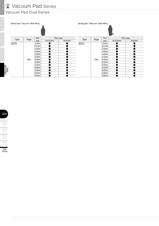
VPMC
Spring type / Top port / Barb fitting Spring type / Side port / Barb fitting
VPMD
Type PagePort size
Port size4×2.5mm
647
2×4mm3.5×7mm4×10mm4×20mm4×30mm5×10mm5×20mm5×30mm6×10mm6×20mm6×30mm8×20mm8×30mm
●●●●●●●●●●●●●
Type PagePort size
Port size4×2.5mm
648
2×4mm3.5×7mm4×10mm4×20mm4×30mm5×10mm5×20mm5×30mm6×10mm6×20mm6×30mm8×20mm8×30mm
●●●●●●●●●●●●●
6×4mm●●●●●●●●●●●●●
6×4mm●●●●●●●●●●●●●
632
VACUUM
PAD
SoftSeries
Soft BellowsSeries
SkidproofSeries
UltrathinSeries
FlatSeries
Long StrokeSeries
VacuumCylinder
AirPincette
Mark-freeSeries
OvalSeries
http://en.pisco.co.jp
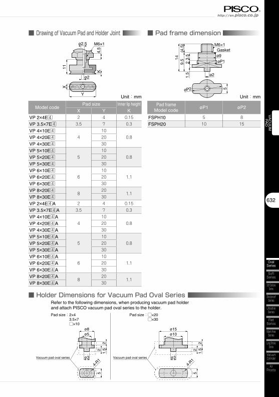
■ Drawing of Vacuum Pad and Holder JointM6×1
4.5
Y
X
K
11
ø2
ø2.5
■ Pad frame dimension
■ Holder Dimensions for Vacuum Pad Oval Series
Gasket
9.5 3.
52 øP1
ø914
1.5
(4.5
) M6×1
5øP2
ø2
ø15ø10
ø3ø3
55
4-R1
22
1.52
21.
5
4-R1
ø8ø5
Refer to the following dimensions, when producing vacuum pad holderand attach PISCO vacuum pad oval series to the holder.
Pad size:2×43.5×7□×10
Pad size:□×20□×30
Vacuum pad oval series Vacuum pad oval series
Unit:mm
Model codePad size Inner lip height
KX Y
VP 2×4E4 2 4 0.15
VP 3.5×7E4 3.5 7 0.3
VP 4×10E44
100.8VP 4×20E4 20
VP 4×30E4 30
VP 5×10E45
100.8VP 5×20E4 20
VP 5×30E4 30
VP 6×10E46
101.1VP 6×20E4 20
VP 6×30E4 30
VP 8×20E48
201.1
VP 8×30E4 30
VP 2×4E4A 2 4 0.15
VP 3.5×7E4A 3.5 7 0.3
VP 4×10E4A4
100.8VP 4×20E4A 20
VP 4×30E4A 30
VP 5×10E4A5
100.8VP 5×20E4A 20
VP 5×30E4A 30
VP 6×10E4A6
101.1VP 6×20E4A 20
VP 6×30E4A 30
VP 8×20E4A8
201.1
VP 8×30E4A 30
Unit:mm
Pad frame Model code
øP1 øP2
FSPH10 5 8
FSPH20 10 15
633
Vacuum Pad SeriesVacuum Pad Oval Series
VACUUM
PAD
OvalSeries
Multi-BellowsSeries
SpongeSeries
StandardSeries
BellowsSeries
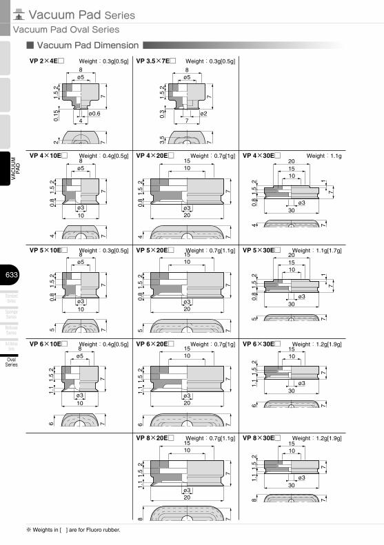
■ Vacuum Pad Dimension
VP 4×10E□ VP 4×20E□ VP 4×30E□
VP 5×10E□ VP 5×20E□ VP 5×30E□
VP 6×10E□ VP 6×20E□ VP 6×30E□
VP 8×20E□ VP 8×30E□
ø58
ø310
21.
50.
84 7
7
1510
ø320
21.
50.
84 7
7
VP 2×4E□ VP 3.5×7E□
201510
ø330
21.
50.
84 7
17
ø58
ø310
21.
50.
85 7
7
1510
ø320
21.
50.
85 7
7
201510
ø330
21.
50.
85 7
17
ø58
ø310
21.
51.
16 7
7
1510
ø320
21.
51.
16 7
7
1510
ø330
21.
51.
16 7
7
1510
ø320
21.
51.
18 7
7
1510
ø330
21.
51.
18 7
7
ø58
71.5
2
720.
15 ø0.64
ø58
71.5
2
73.5
0.3 ø2
7
Weight:0.3g[0.5g] Weight:0.3g[0.5g]
Weight:0.4g[0.5g] Weight:0.7g[1g]
Weight:0.3g[0.5g] Weight:0.7g[1.1g]
Weight:1.1g
Weight:1.1g[1.7g]
Weight:0.4g[0.5g] Weight:0.7g[1g] Weight:1.2g[1.9g]
Weight:0.7g[1.1g] Weight:1.2g[1.9g]
※ Weights in [ ] are for Fluoro rubber.
634
VACUUM
PAD
SoftSeries
Soft BellowsSeries
SkidproofSeries
UltrathinSeries
FlatSeries
Long StrokeSeries
VacuumCylinder
AirPincette
Mark-freeSeries
OvalSeries
http://en.pisco.co.jp
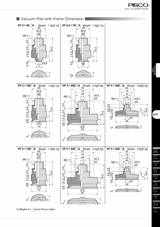
■ Vacuum Pad with frame Dimension
VP 4×10E□A VP 4×20E□A VP 4×30E□A
VP 5×10E□A VP 5×20E□A VP 5×30E□A
ø310
24.
53.
51.
50.
84 7
715
.5
ø2ø2.5ø9
ø330
21.
50.
84 7
17
201510ø9
ø2.5ø2
15.5
3.5
4.5
ø320
21.
50.
84 7
7
1510
3.5
4.5
15.5
ø2ø2.5
ø9
ø310
21.
50.
85 7
7
ø2.5ø9
ø2
4.5
3.5
15.5
201510
ø330
21.
50.
85 7
17
ø9ø2.5ø2
15.5
3.5
4.5
ø320
21.
50.
85 7
7
1510ø9
ø2.5ø2
3.5
4.5
15.5
M6×1 M6×1
VP 2×4E□A
ø0.64
24.
53.
51.
50.
152 7
715
.5
ø2ø2.5ø9
M6×1
VP 3.5×7E□A
ø27
24.
53.
51.
50.
33.
5
77
15.5
ø2ø2.5ø9
M6×1
M6×1
M6×1 M6×1M6×1
Weight:1.9g[2.1g] Weight:1.9g[2.1g]
Weight:1.9g[2.1g] Weight:2.4g[2.8g] Weight:2.8g[3.5g]
Weight:1.9g[2.1g] Weight:2.4g[2.8g] Weight:2.8g[3.4g]
※ Weights in [ ] are for Fluoro rubber.
635
Vacuum Pad SeriesVacuum Pad Oval Series
VACUUM
PAD
OvalSeries
Multi-BellowsSeries
SpongeSeries
StandardSeries
BellowsSeries
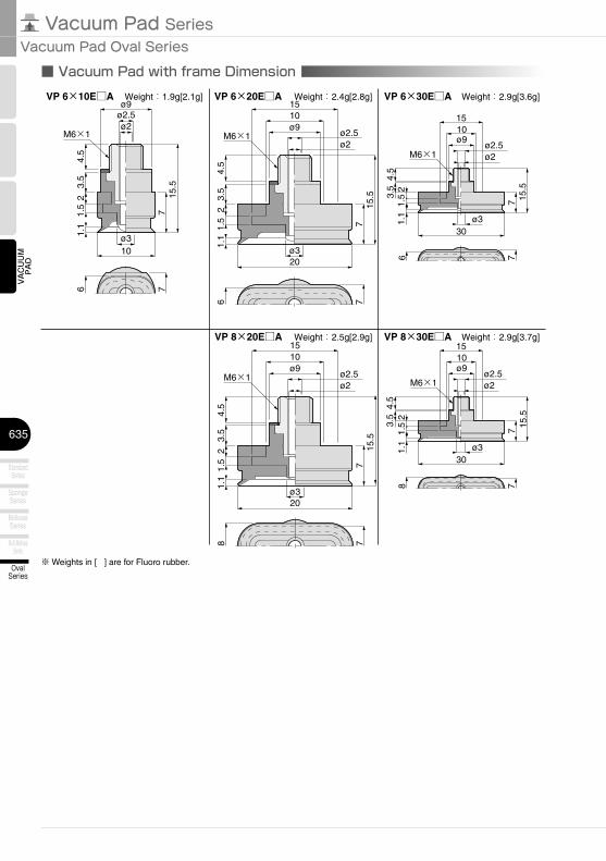
VP 8×20E□A VP 8×30E□A1510
ø330
21.
51.
18 7
7
ø9ø2.5ø2
15.5
4.5
3.5
ø320
21.
51.
18 7
7
1510ø9
ø2.5ø2
3.5
4.5
15.5
M6×1M6×1
VP 6×10E□A VP 6×20E□A VP 6×30E□A
ø310
21.
51.
16 7
7
ø2.5ø9
ø2
4.5
3.5
15.5
ø330
21.
51.
16 7
7
1510ø9
ø2.5ø2
15.5
4.5
3.5
ø320
21.
51.
16 7
7
1510ø9
ø2.5ø2
3.5
4.5
15.5
M6×1 M6×1
M6×1
Weight:1.9g[2.1g] Weight:2.4g[2.8g] Weight:2.9g[3.6g]
Weight:2.5g[2.9g] Weight:2.9g[3.7g]
■ Vacuum Pad with frame Dimension
※ Weights in [ ] are for Fluoro rubber.
636
VACUUM
PAD
SoftSeries
Soft BellowsSeries
SkidproofSeries
UltrathinSeries
FlatSeries
Long StrokeSeries
VacuumCylinder
AirPincette
Mark-freeSeries
OvalSeries
http://en.pisco.co.jp
VPA
XY
38.7
16.6 Hex.14
2-4
18
11.7
ø6 M14×1
2-Hex.1711
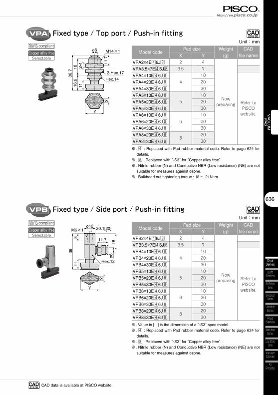
Fixed type / Top port / Push-in fitting CAD-2D & 3D-
VPB
ø12
11.7
Hex.12
20.1[20]M6×1
18ø6
X
Y
3911
8
Fixed type / Side port / Push-in fitting CAD-2D & 3D-
CAD-2D & 3D- CAD data is available at PISCO website.
compliant
compliantCopper alloy free
Selectable
Copper alloy freeSelectable
Unit:mm
Model codePad size Weight
(g)CAD
file nameX Y
VPA2×4E46J8 2 4
Now preparing
VPA3.5×7E46J8 3.5 7
VPA4×10E46J84
10
Refer to PISCO
website.
VPA4×20E46J8 20
VPA4×30E46J8 30
VPA5×10E46J85
10
VPA5×20E46J8 20
VPA5×30E46J8 30
VPA6×10E46J86
10
VPA6×20E46J8 20
VPA6×30E46J8 30
VPA8×20E46J88
20
VPA8×30E46J8 30
※ . 4 : Replaced with Pad rubber material code. Refer to page 624 for details.
※ . 8 : Replaced with “-S3” for “Copper alloy free” .※ . Nitrile rubber (N) and Conductive NBR (Low resistance) (NE) are not
suitable for measures against ozone.※ . Bulkhead nut tightening torque : 18 ~ 21N・m
Unit:mm
Model codePad size Weight
(g)CAD
file nameX Y
VPB2×4E46J8 2 4
Now preparing
VPB3.5×7E46J8 3.5 7
VPB4×10E46J84
10
Refer to PISCO
website.
VPB4×20E46J8 20
VPB4×30E46J8 30
VPB5×10E46J85
10
VPB5×20E46J8 20
VPB5×30E46J8 30
VPB6×10E46J86
10
VPB6×20E46J8 20
VPB6×30E46J8 30
VPB8×20E46J88
20
VPB8×30E46J8 30
※ . Value in [ ] is the dimension of a “-S3” spec model.※ . 4 : Replaced with Pad rubber material code. Refer to page 624 for
details.※ . 8 : Replaced with “-S3” for “Copper alloy free” .※ . Nitrile rubber (N) and Conductive NBR (Low resistance) (NE) are not
suitable for measures against ozone.
637
Vacuum Pad SeriesVacuum Pad Oval Series
VACUUM
PAD
OvalSeries
Multi-BellowsSeries
SpongeSeries
StandardSeries
BellowsSeries
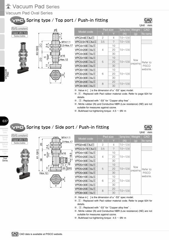
VPD
ø16
18.56
(Str
oke)
20
M14×1
20.1[20]
Hex.12
2-4
2-Hex.17
11.7 ø6
X
Y
61.1
[61]
38
11
Spring type / Side port / Push-in fitting CAD-2D & 3D-
CAD-2D & 3D- CAD data is available at PISCO website.
VPC
ø16
2-4 2-Hex.17
M14×1
11.7
ø6
6(S
trok
e)
Hex.12
20
X
Y
63.1
[63]
29
11
Spring type / Top port / Push-in fitting CAD-2D & 3D-
compliantCopper alloy free
Selectable
compliantCopper alloy free
Selectable
Unit:mm
Model codePad size Spring force
(N)Weight
(g)CAD
file nameX Y
VPD2×4E46J8 2 4 7.0〜12.6
Now preparing
VPD3.5×7E46J8 3.5 7 7.0〜12.6
VPD4×10E46J84
107.0〜12.6
Refer to PISCO
website.
VPD4×20E46J8 20
VPD4×30E46J8 30
VPD5×10E46J85
107.0〜12.6VPD5×20E46J8 20
VPD5×30E46J8 30
VPD6×10E46J86
107.0〜12.6VPD6×20E46J8 20
VPD6×30E46J8 30
VPD8×20E46J88
207.0〜12.6
VPD8×30E46J8 30
※ . Value in [ ] is the dimension of a “-S3” spec model.※ . 4 : Replaced with Pad rubber material code. Refer to page 624 for
details.※ . 8 : Replaced with “-S3” for “Copper alloy free” .※ . Nitrile rubber (N) and Conductive NBR (Low resistance) (NE) are not
suitable for measures against ozone.※ . Bulkhead nut tightening torque : 4.5 ~ 6N・m
Unit:mm
Model codePad size Spring force
(N)Weight
(g)CAD
file nameX Y
VPC2×4E46J8 2 4 7.0〜12.6
Now preparing
VPC3.5×7E46J8 3.5 7 7.0〜12.6
VPC4×10E46J84
107.0〜12.6
Refer to PISCO
website.
VPC4×20E46J8 20
VPC4×30E46J8 30
VPC5×10E46J85
107.0〜12.6VPC5×20E46J8 20
VPC5×30E46J8 30
VPC6×10E46J86
107.0〜12.6VPC6×20E46J8 20
VPC6×30E46J8 30
VPC8×20E46J88
207.0〜12.6
VPC8×30E46J8 30
※ . Value in [ ] is the dimension of a “-S3” spec model.※ . 4 : Replaced with Pad rubber material code. Refer to page 624 for
details.※ . 8 : Replaced with “-S3” for “Copper alloy free” .※ . Nitrile rubber (N) and Conductive NBR (Low resistance) (NE) are not
suitable for measures against ozone.※ . Bulkhead nut tightening torque : 4.5 ~ 6N・m
638
VACUUM
PAD
SoftSeries
Soft BellowsSeries
SkidproofSeries
UltrathinSeries
FlatSeries
Long StrokeSeries
VacuumCylinder
AirPincette
Mark-freeSeries
OvalSeries
http://en.pisco.co.jp
VPAE
2-ø3.2
20
11.7
43.1
[43]
ø9
12 X
Y
28
ø12ø6
1.5
725
Y
12 X
2-ø3.2
20
ø9
28
ø12ø6
11.7
43.1
[43]
251.
57
●VPAE□×10E□ ●VPAE□×20、30E□
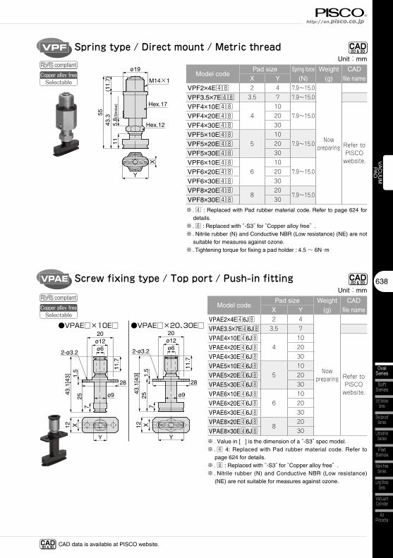
Screw fixing type / Top port / Push-in fitting CAD-2D & 3D-
VPF
5.8(
Str
oke)
Hex.12
M14×1
Hex.17(1
1.7)
ø19
X
Y
5543
.311
Spring type / Direct mount / Metric thread CAD-2D & 3D-
CAD-2D & 3D- CAD data is available at PISCO website.
compliantCopper alloy free
Selectable
compliantCopper alloy free
Selectable
Unit:mm
Model codePad size Weight
(g)CAD
file nameX Y
VPAE2×4E46J8 2 4
Now preparing
VPAE3.5×7E46J8 3.5 7
VPAE4×10E46J84
10
Refer to PISCO
website.
VPAE4×20E46J8 20
VPAE4×30E46J8 30
VPAE5×10E46J85
10
VPAE5×20E46J8 20
VPAE5×30E46J8 30
VPAE6×10E46J86
10
VPAE6×20E46J8 20
VPAE6×30E46J8 30
VPAE8×20E46J88
20
VPAE8×30E46J8 30
※ . Value in [ ] is the dimension of a “-S3” spec model.※ . 4 4: Replaced with Pad rubber material code. Refer to
page 624 for details.※ . 8 : Replaced with “-S3” for “Copper alloy free” .※ . Nitrile rubber (N) and Conductive NBR (Low resistance)
(NE) are not suitable for measures against ozone.
Unit:mm
Model codePad size Spring force
(N)Weight
(g)CAD
file nameX Y
VPF2×4E48 2 4 7.9〜15.0
Now preparing
VPF3.5×7E48 3.5 7 7.9〜15.0
VPF4×10E484
107.9〜15.0
Refer to PISCO
website.
VPF4×20E48 20
VPF4×30E48 30
VPF5×10E485
107.9〜15.0VPF5×20E48 20
VPF5×30E48 30
VPF6×10E486
107.9〜15.0VPF6×20E48 20
VPF6×30E48 30
VPF8×20E488
207.9〜15.0
VPF8×30E48 30
※ . 4 : Replaced with Pad rubber material code. Refer to page 624 for details.
※ . 8 : Replaced with “-S3” for “Copper alloy free” .※ . Nitrile rubber (N) and Conductive NBR (Low resistance) (NE) are not
suitable for measures against ozone.※ . Tightening torque for fixing a pad holder : 4.5 ~ 6N・m
639
Vacuum Pad SeriesVacuum Pad Oval Series
VACUUM
PAD
OvalSeries
Multi-BellowsSeries
SpongeSeries
StandardSeries
BellowsSeries
VPA
X
Y
2-4
7
ø6×ø4(Tube O.D. x I.D.)
18
Hex.12
M12×12-Hex.14
45[4
4.9]
1711
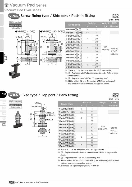
Fixed type / Top port / Barb fitting CAD-2D & 3D-
CAD-2D & 3D- CAD data is available at PISCO website.
VPBE
ø9 20
Y
X12
2-ø3.2
28
20
22.1[22]11.7
ø12ø6
36 341.
5
7
ø9 20Y
12 X
20
28
ø12
22.1[22]11.7
ø6
36
2-ø3.2
71.
5
34
●VPBE□×10E□ ●VPBE□×20、30E□
Screw fixing type / Side port / Push-in fitting CAD-2D & 3D-
compliantCopper alloy free
Selectable
compliantCopper alloy free
Selectable
Unit:mm
Model codePad size Weight
(g)CAD
file nameX Y
VPA2×4E46B8 2 4
Now preparing
VPA3.5×7E46B8 3.5 7
VPA4×10E46B84
10
Refer to PISCO
website.
VPA4×20E46B8 20
VPA4×30E46B8 30
VPA5×10E46B85
10
VPA5×20E46B8 20
VPA5×30E46B8 30
VPA6×10E46B86
10
VPA6×20E46B8 20
VPA6×30E46B8 30
VPA8×20E46B88
20
VPA8×30E46B8 30
※ . Value in [ ] is the dimension of a “-S3” spec model.※ . 4 : Replaced with Pad rubber material code. Refer to page 624 for
details.※ . 8 : Replaced with “-S3” for “Copper alloy free” .※ . Nitrile rubber (N) and Conductive NBR (Low resistance) (NE) are not
suitable for measures against ozone.※ . Bulkhead nut tightening torque : 12 ~ 14N・m
Unit:mm
Model codePad size Weight
(g)CAD
file nameX Y
VPBE2×4E46J8 2 4
Now preparing
VPBE3.5×7E46J8 3.5 7
VPBE4×10E46J84
10
Refer to PISCO
website.
VPBE4×20E46J8 20
VPBE4×30E46J8 30
VPBE5×10E46J85
10
VPBE5×20E46J8 20
VPBE5×30E46J8 30
VPBE6×10E46J86
10
VPBE6×20E46J8 20
VPBE6×30E46J8 30
VPBE8×20E46J88
20
VPBE8×30E46J8 30
※ . Value in [ ] is the dimension of a “-S3” spec model.※ . 4 : Replaced with Pad rubber material code. Refer to page
624 for details.※ . 8 : Replaced with “-S3” for “Copper alloy free” .※ . Nitrile rubber (N) and Conductive NBR (Low resistance)
(NE) are not suitable for measures against ozone.

640
VACUUM
PAD
SoftSeries
Soft BellowsSeries
SkidproofSeries
UltrathinSeries
FlatSeries
Long StrokeSeries
VacuumCylinder
AirPincette
Mark-freeSeries
OvalSeries
http://en.pisco.co.jp
VPC
ø16
2-4
ø6×ø4(Tube O.D. x I.D.)
7
M14×1
2-Hex.17
Hex.12
20
6(S
trok
e)
X
Y
59.1
[59]
29
11
Spring type / Top port / Barb fitting CAD-2D & 3D-
VPB
16.1[16]ø12
7
ø6×
ø4
( Tub
e O
.D. x
I.D
.)18
Hex.12
M6×1
XY
3911
8
Fixed type / Side port / Barb fitting CAD-2D & 3D-
CAD-2D & 3D- CAD data is available at PISCO website.
compliantCopper alloy free
Selectable
compliantCopper alloy free
Selectable
Unit:mm
Model codePad size Weight
(g)CAD
file nameX Y
VPB2×4E46B8 2 4
Now preparing
VPB3.5×7E46B8 3.5 7
VPB4×10E46B84
10
Refer to PISCO
website.
VPB4×20E46B8 20
VPB4×30E46B8 30
VPB5×10E46B85
10
VPB5×20E46B8 20
VPB5×30E46B8 30
VPB6×10E46B86
10
VPB6×20E46B8 20
VPB6×30E46B8 30
VPB8×20E46B88
20
VPB8×30E46B8 30
※ . 4 : Replaced with Pad rubber material code. Refer to page 624 for details.
※ . 8 : Replaced with “-S3” for “Copper alloy free” .※ . Nitrile rubber (N) and Conductive NBR (Low resistance) (NE) are not
suitable for measures against ozone.
Unit:mm
Model codePad size Spring force
(N)Weight
(g)CAD
file nameX Y
VPC2×4E46B8 2 4 7.0〜12.6
Now preparing
VPC3.5×7E46B8 3.5 7 7.0〜12.6
VPC4×10E46B84
107.0〜12.6
Refer to PISCO
website.
VPC4×20E46B8 20
VPC4×30E46B8 30
VPC5×10E46B85
107.0〜12.6VPC5×20E46B8 20
VPC5×30E46B8 30
VPC6×10E46B86
107.0〜12.6VPC6×20E46B8 20
VPC6×30E46B8 30
VPC8×20E46B88
207.0〜12.6
VPC8×30E46B8 30
※ . Value in [ ] is the dimension of a “-S3” spec model.※ . 4 : Replaced with Pad rubber material code. Refer to page 624 for
details.※ . 8 : Replaced with “-S3” for “Copper alloy free” .※ . Nitrile rubber (N) and Conductive NBR (Low resistance) (NE) are not
suitable for measures against ozone.※ . Bulkhead nut tightening torque : 4.5 ~ 6N・m
641
Vacuum Pad SeriesVacuum Pad Oval Series
VACUUM
PAD
OvalSeries
Multi-BellowsSeries
SpongeSeries
StandardSeries
BellowsSeries
VPD
ø16
18.5
Hex.12
6(S
trok
e)
2-Hex.17
7
ø6×
ø4
( Tub
e O
.D. x
I.D
.)
M14×1
16.1[16]
20
2-4
X
Y
61.1
[61]
38
11
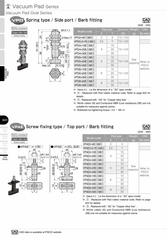
Spring type / Side port / Barb fitting CAD-2D & 3D-
VPAE
12 X
Y
2-ø3.2
ø9
28
20ø12
ø6×ø4(Tube O.D. x I.D.)
7
38.6
[38.
5]
257
1.5
Y
12 X
2-ø3.2
ø9
28
20ø12
ø6×ø4(Tube O.D. x I.D.)
7
38.6
[38.
5]
257
1.5
●VPAE□×10E□ ●VPAE□×20、30E□
Screw fixing type / Top port / Barb fitting CAD-2D & 3D-
CAD-2D & 3D- CAD data is available at PISCO website.
compliantCopper alloy free
Selectable
compliantCopper alloy free
Selectable
Unit:mm
Model codePad size Spring force
(N)Weight
(g)CAD
file nameX Y
VPD2×4E46B8 2 4 7.0〜12.6
Now preparing
VPD3.5×7E46B8 3.5 7 7.0〜12.6
VPD4×10E46B84
107.0〜12.6
Refer to PISCO
website.
VPD4×20E46B8 20
VPD4×30E46B8 30
VPD5×10E46B85
107.0〜12.6VPD5×20E46B8 20
VPD5×30E46B8 30
VPD6×10E46B86
107.0〜12.6VPD6×20E46B8 20
VPD6×30E46B8 30
VPD8×20E46B88
207.0〜12.6
VPD8×30E46B8 30
※ . Value in [ ] is the dimension of a “-S3” spec model.※ . 4 : Replaced with Pad rubber material code. Refer to page 624 for
details.※ . 8 : Replaced with “-S3” for “Copper alloy free” .※ . Nitrile rubber (N) and Conductive NBR (Low resistance) (NE) are not
suitable for measures against ozone.※ . Bulkhead nut tightening torque : 4.5 ~ 6N・m
Unit:mm
Model codePad size Weight
(g)CAD
file nameX Y
VPAE2×4E46B8 2 4
Now preparing
VPAE3.5×7E46B8 3.5 7
VPAE4×10E46B84
10
Refer to PISCO
website.
VPAE4×20E46B8 20
VPAE4×30E46B8 30
VPAE5×10E46B85
10
VPAE5×20E46B8 20
VPAE5×30E46B8 30
VPAE6×10E46B86
10
VPAE6×20E46B8 20
VPAE6×30E46B8 30
VPAE8×20E46B88
20
VPAE8×30E46B8 30
※ . Value in [ ] is the dimension of a “-S3” spec model.※ . 4 : Replaced with Pad rubber material code. Refer to page
624 for details.※ . 8 : Replaced with “-S3” for “Copper alloy free” .※ . Nitrile rubber (N) and Conductive NBR (Low resistance)
(NE) are not suitable for measures against ozone.
642
VACUUM
PAD
SoftSeries
Soft BellowsSeries
SkidproofSeries
UltrathinSeries
FlatSeries
Long StrokeSeries
VacuumCylinder
AirPincette
Mark-freeSeries
OvalSeries
http://en.pisco.co.jp
VPMA
10.9
2-3
163.
411
X
ø4
2-Hex. 12
Hex. 10
M10×1
33.1
Y
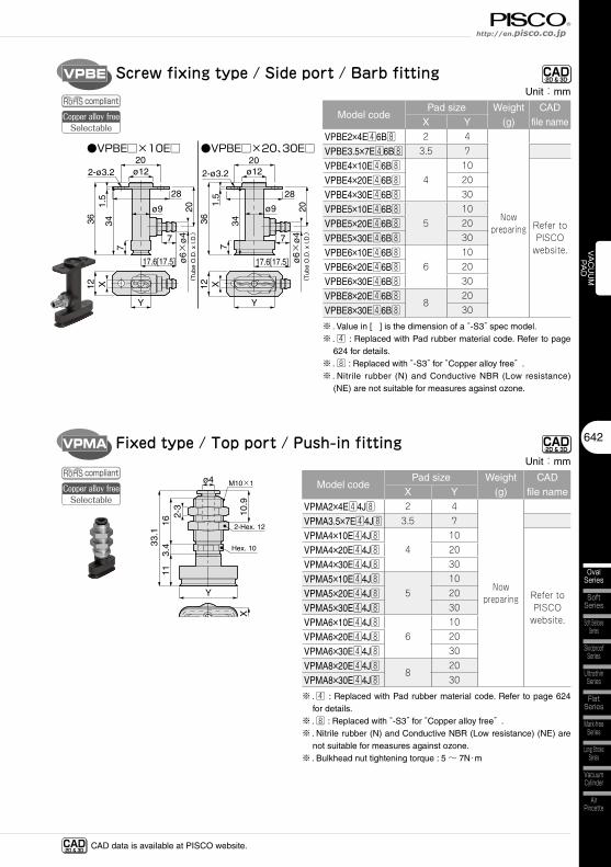
Fixed type / Top port / Push-in fittingUnit:mm
Model codePad size Weight
(g)CAD
file nameX Y
VPMA2×4E44J8 2 4
Now preparing
VPMA3.5×7E44J8 3.5 7
VPMA4×10E44J84
10
Refer to PISCO
website.
VPMA4×20E44J8 20
VPMA4×30E44J8 30
VPMA5×10E44J85
10
VPMA5×20E44J8 20
VPMA5×30E44J8 30
VPMA6×10E44J86
10
VPMA6×20E44J8 20
VPMA6×30E44J8 30
VPMA8×20E44J88
20
VPMA8×30E44J8 30
※ . 4 : Replaced with Pad rubber material code. Refer to page 624 for details.
※ . 8 : Replaced with “-S3” for “Copper alloy free” .※ . Nitrile rubber (N) and Conductive NBR (Low resistance) (NE) are
not suitable for measures against ozone.※ . Bulkhead nut tightening torque : 5 ~ 7N・m
VPBE
ø9 20
Y
12 X
17.6[17.5] ø6×
ø4
( Tub
e O
.D. x
I.D
.)7
20
28
ø12
36
2-ø3.2
7
1.5
34
ø9 20Y
12 X
17.6[17.5] ø6×
ø4
( Tub
e O
.D. x
I.D
.)7
20
28
ø12
36
2-ø3.2
71.
5
34
●VPBE□×10E□ ●VPBE□×20、30E□
Screw fixing type / Side port / Barb fitting CAD-2D & 3D-
CAD-2D & 3D-
CAD-2D & 3D- CAD data is available at PISCO website.
compliantCopper alloy free
Selectable
compliantCopper alloy free
Selectable
Unit:mm
Model codePad size Weight
(g)CAD
file nameX Y
VPBE2×4E46B8 2 4
Now preparing
VPBE3.5×7E46B8 3.5 7
VPBE4×10E46B84
10
Refer to PISCO
website.
VPBE4×20E46B8 20
VPBE4×30E46B8 30
VPBE5×10E46B85
10
VPBE5×20E46B8 20
VPBE5×30E46B8 30
VPBE6×10E46B86
10
VPBE6×20E46B8 20
VPBE6×30E46B8 30
VPBE8×20E46B88
20
VPBE8×30E46B8 30
※ . Value in [ ] is the dimension of a “-S3” spec model.※ . 4 : Replaced with Pad rubber material code. Refer to page
624 for details.※ . 8 : Replaced with “-S3” for “Copper alloy free” .※ . Nitrile rubber (N) and Conductive NBR (Low resistance)
(NE) are not suitable for measures against ozone.
643
Vacuum Pad SeriesVacuum Pad Oval Series
VACUUM
PAD
OvalSeries
Multi-BellowsSeries
SpongeSeries
StandardSeries
BellowsSeries
VPMB
X
12ø8ø4
2111
ø10 17.7[17.6]
10.9
Hex. 10
M5×0.832
Y
6
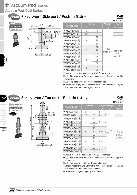
Fixed type / Side port / Push-in fittingUnit:mm
Model codePad size Weight
(g)CAD
file nameX Y
VPMB2×4E44J8 2 4
Now preparing
VPMB3.5×7E44J8 3.5 7
VPMB4×10E44J84
10
Refer to PISCO
website.
VPMB4×20E44J8 20
VPMB4×30E44J8 30
VPMB5×10E44J85
10
VPMB5×20E44J8 20
VPMB5×30E44J8 30
VPMB6×10E44J86
10
VPMB6×20E44J8 20
VPMB6×30E44J8 30
VPMB8×20E44J88
20
VPMB8×30E44J8 30
※ . Value in [ ] is the dimension of a “-S3” spec model.※ . 4 : Replaced with Pad rubber material code. Refer to page 624
for details.※ . 8 : Replaced with “-S3” for “Copper alloy free” .※ . Nitrile rubber (N) and Conductive NBR (Low resistance) (NE) are
not suitable for measures against ozone.
VPMC
X
10.9
2-3
1613
.811
ø4
2-Hex. 12
Hex. 10
M10×1
M6×1
4(S
trok
e)53.5
[ 53.
4]
Y
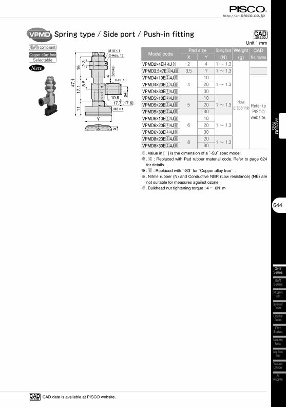
Spring type / Top port / Push-in fittingUnit:mm
Model codePad size Spring force
(N)Weight
(g)CAD
file nameX Y
VPMC2×4E44J8 2 4 1 〜 1.3
Now preparing
VPMC3.5×7E44J8 3.5 7 1 〜 1.3
VPMC4×10E44J84
101 〜 1.3
Refer to PISCO
website.
VPMC4×20E44J8 20
VPMC4×30E44J8 30
VPMC5×10E44J85
101 〜 1.3VPMC5×20E44J8 20
VPMC5×30E44J8 30
VPMC6×10E44J86
101 〜 1.3VPMC6×20E44J8 20
VPMC6×30E44J8 30
VPMC8×20E44J88
201 〜 1.3
VPMC8×30E44J8 30
※ . Value in [ ] is the dimension of a “-S3” spec model.※ . 4 : Replaced with Pad rubber material code. Refer to page 624
for details.※ . 8 : Replaced with “-S3” for “Copper alloy free” .※ . Nitrile rubber (N) and Conductive NBR (Low resistance) (NE) are
not suitable for measures against ozone.※ . Bulkhead nut tightening torque : 4 ~ 6N・m
New
CAD-2D & 3D-
CAD-2D & 3D-
CAD-2D & 3D- CAD data is available at PISCO website.
compliantCopper alloy free
Selectable
compliantCopper alloy free
Selectable
644
VACUUM
PAD
SoftSeries
Soft BellowsSeries
SkidproofSeries
UltrathinSeries
FlatSeries
Long StrokeSeries
VacuumCylinder
AirPincette
Mark-freeSeries
OvalSeries
http://en.pisco.co.jp
VPMD
X
ø4
2-3
8.5
1617
.111
10.917.7 [17.6]
2-Hex. 12
Hex. 10
M10×1
M6×14 (S
trok
e)
47.1
Y
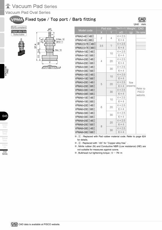
Spring type / Side port / Push-in fittingUnit:mm
Model codePad size Spring force
(N)Weight
(g)CAD
file nameX Y
VPMD2×4E44J8 2 4 1 〜 1.3
Now preparing
VPMD3.5×7E44J8 3.5 7 1 〜 1.3
VPMD4×10E44J84
101 〜 1.3
Refer to PISCO
website.
VPMD4×20E44J8 20
VPMD4×30E44J8 30
VPMD5×10E44J85
101 〜 1.3VPMD5×20E44J8 20
VPMD5×30E44J8 30
VPMD6×10E44J86
101 〜 1.3VPMD6×20E44J8 20
VPMD6×30E44J8 30
VPMD8×20E44J88
201 〜 1.3
VPMD8×30E44J8 30
※ . Value in [ ] is the dimension of a “-S3” spec model.※ . 4 : Replaced with Pad rubber material code. Refer to page 624
for details.※ . 8 : Replaced with “-S3” for “Copper alloy free” .※ . Nitrile rubber (N) and Conductive NBR (Low resistance) (NE) are
not suitable for measures against ozone.※ . Bulkhead nut tightening torque : 4 ~ 6N・m
New
CAD-2D & 3D-
CAD-2D & 3D- CAD data is available at PISCO website.
compliantCopper alloy free
Selectable
645
Vacuum Pad SeriesVacuum Pad Oval Series
VACUUM
PAD
OvalSeries
Multi-BellowsSeries
SpongeSeries
StandardSeries
BellowsSeries
VPMA
X
7
2-3
163.
411
øD
2-Hex. 12
Hex. 10
M10×1
37.4
Y
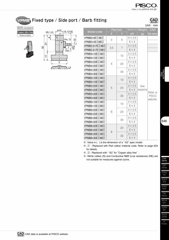
Fixed type / Top port / Barb fittingUnit:mm
Model codePad size Tube O.D. x I.D.
øDWeight
(g)CAD
file nameX Y
VPMA2×4E44B82 4
4×2.5
Now preparing
VPMA2×4E46B8 6×4
VPMA3.5×7E44B83.5 7
4×2.5
VPMA3.5×7E46B8 6×4
VPMA4×10E44B8
4
104×2.5
Refer to PISCO
website.
VPMA4×10E46B8 6×4
VPMA4×20E44B820
4×2.5
VPMA4×20E46B8 6×4
VPMA4×30E44B830
4×2.5
VPMA4×30E46B8 6×4
VPMA5×10E44B8
5
104×2.5
VPMA5×10E46B8 6×4
VPMA5×20E44B820
4×2.5
VPMA5×20E46B8 6×4
VPMA5×30E44B830
4×2.5
VPMA5×30E46B8 6×4
VPMA6×10E44B8
6
104×2.5
VPMA6×10E46B8 6×4
VPMA6×20E44B820
4×2.5
VPMA6×20E46B8 6×4
VPMA6×30E44B830
4×2.5
VPMA6×30E46B8 6×4
VPMA8×20E44B8
820
4×2.5
VPMA8×20E46B8 6×4
VPMA8×30E44B830
4×2.5
VPMA8×30E46B8 6×4
※ . 4 : Replaced with Pad rubber material code. Refer to page 624 for details.
※ . 8 : Replaced with “-S3” for “Copper alloy free” .※ . Nitrile rubber (N) and Conductive NBR (Low resistance) (NE) are
not suitable for measures against ozone.※ . Bulkhead nut tightening torque : 5 ~ 7N・m
CAD-2D & 3D-
CAD-2D & 3D- CAD data is available at PISCO website.
compliantCopper alloy free
Selectable
646
VACUUM
PAD
SoftSeries
Soft BellowsSeries
SkidproofSeries
UltrathinSeries
FlatSeries
Long StrokeSeries
VacuumCylinder
AirPincette
Mark-freeSeries
OvalSeries
http://en.pisco.co.jp
VPMB
X
12
2111
øD
ø10 15.1[15]
7
M5×0.8
Hex. 10
Hex. 7
32
Y
6
Fixed type / Side port / Barb fittingUnit:mm
Model codePad size Tube O.D. x I.D.
øDWeight
(g)CAD
file nameX Y
VPMB2×4E44B82 4
4×2.5
Now preparing
VPMB2×4E46B8 6×4
VPMB3.5×7E44B83.5 7
4×2.5
VPMB3.5×7E46B8 6×4
VPMB4×10E44B8
4
104×2.5
Refer to PISCO
website.
VPMB4×10E46B8 6×4
VPMB4×20E44B820
4×2.5
VPMB4×20E46B8 6×4
VPMB4×30E44B830
4×2.5
VPMB4×30E46B8 6×4
VPMB5×10E44B8
5
104×2.5
VPMB5×10E46B8 6×4
VPMB5×20E44B820
4×2.5
VPMB5×20E46B8 6×4
VPMB5×30E44B830
4×2.5
VPMB5×30E46B8 6×4
VPMB6×10E44B8
6
104×2.5
VPMB6×10E46B8 6×4
VPMB6×20E44B820
4×2.5
VPMB6×20E46B8 6×4
VPMB6×30E44B830
4×2.5
VPMB6×30E46B8 6×4
VPMB8×20E44B8
820
4×2.5
VPMB8×20E46B8 6×4
VPMB8×30E44B830
4×2.5
VPMB8×30E46B8 6×4
※ . Value in [ ] is the dimension of a “-S3” spec model.※ . 4 : Replaced with Pad rubber material code. Refer to page 624
for details.※ . 8 : Replaced with “-S3” for “Copper alloy free” .※ . Nitrile rubber (N) and Conductive NBR (Low resistance) (NE) are
not suitable for measures against ozone.
CAD-2D & 3D-
CAD-2D & 3D- CAD data is available at PISCO website.
compliantCopper alloy free
Selectable
647
Vacuum Pad SeriesVacuum Pad Oval Series
VACUUM
PAD
OvalSeries
Multi-BellowsSeries
SpongeSeries
StandardSeries
BellowsSeries
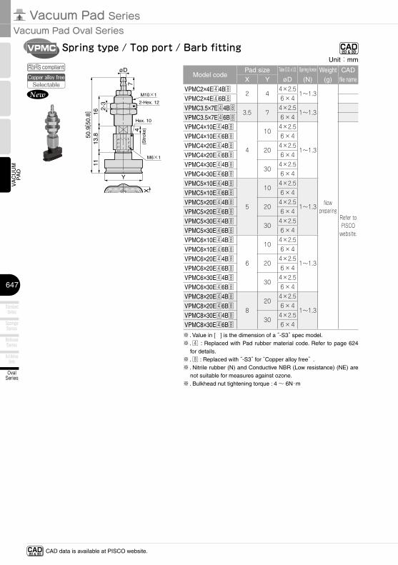
VPMC
X
7
2-3
1613
.811
øD
2-Hex. 12
M10×1
4(S
trok
e)
50.9
[ 50.
8]
Y
Hex. 10
M6×1
Spring type / Top port / Barb fittingUnit:mm
Model codePad size Tube O.D. x I.D.
øD
Spring force
(N)Weight
(g)CAD
file nameX Y
VPMC2×4E44B82 4
4×2.51〜1.3
Now preparing
VPMC2×4E46B8 6×4
VPMC3.5×7E44B83.5 7
4×2.51〜1.3
VPMC3.5×7E46B8 6×4
VPMC4×10E44B8
4
104×2.5
1〜1.3
Refer to PISCO
website.
VPMC4×10E46B8 6×4
VPMC4×20E44B820
4×2.5
VPMC4×20E46B8 6×4
VPMC4×30E44B830
4×2.5
VPMC4×30E46B8 6×4
VPMC5×10E44B8
5
104×2.5
1〜1.3
VPMC5×10E46B8 6×4
VPMC5×20E44B820
4×2.5
VPMC5×20E46B8 6×4
VPMC5×30E44B830
4×2.5
VPMC5×30E46B8 6×4
VPMC6×10E44B8
6
104×2.5
1〜1.3
VPMC6×10E46B8 6×4
VPMC6×20E44B820
4×2.5
VPMC6×20E46B8 6×4
VPMC6×30E44B830
4×2.5
VPMC6×30E46B8 6×4
VPMC8×20E44B8
820
4×2.5
1〜1.3VPMC8×20E46B8 6×4
VPMC8×30E44B830
4×2.5
VPMC8×30E46B8 6×4
※ . Value in [ ] is the dimension of a “-S3” spec model.※ . 4 : Replaced with Pad rubber material code. Refer to page 624
for details.※ . 8 : Replaced with “-S3” for “Copper alloy free” .※ . Nitrile rubber (N) and Conductive NBR (Low resistance) (NE) are
not suitable for measures against ozone.※ . Bulkhead nut tightening torque : 4 ~ 6N・m
New
CAD-2D & 3D-
CAD-2D & 3D- CAD data is available at PISCO website.
compliantCopper alloy free
Selectable
648
VACUUM
PAD
SoftSeries
Soft BellowsSeries
SkidproofSeries
UltrathinSeries
FlatSeries
Long StrokeSeries
VacuumCylinder
AirPincette
Mark-freeSeries
OvalSeries
http://en.pisco.co.jp
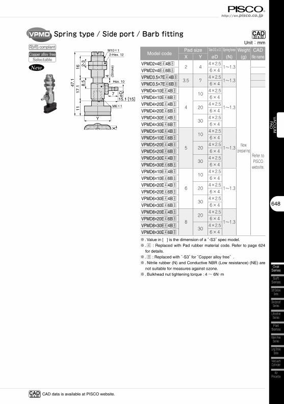
VPMD
M6×1
Hex. 10
øD
2-3
8.5
1617
.111
715.1 [15]
2-Hex. 12M10×1
4 (Str
oke)
47.1
YX
Spring type / Side port / Barb fittingUnit:mm
Model codePad size Tube O.D. x I.D.
øD
Spring force
(N)Weight
(g)CAD
file nameX Y
VPMD2×4E44B82 4
4×2.51〜1.3
Now preparing
VPMD2×4E46B8 6×4
VPMD3.5×7E44B83.5 7
4×2.51〜1.3
VPMD3.5×7E46B8 6×4
VPMD4×10E44B8
4
104×2.5
1〜1.3
Refer to PISCO
website.
VPMD4×10E46B8 6×4
VPMD4×20E44B820
4×2.5
VPMD4×20E46B8 6×4
VPMD4×30E44B830
4×2.5
VPMD4×30E46B8 6×4
VPMD5×10E44B8
5
104×2.5
1〜1.3
VPMD5×10E46B8 6×4
VPMD5×20E44B820
4×2.5
VPMD5×20E46B8 6×4
VPMD5×30E44B830
4×2.5
VPMD5×30E46B8 6×4
VPMD6×10E44B8
6
104×2.5
1〜1.3
VPMD6×10E46B8 6×4
VPMD6×20E44B820
4×2.5
VPMD6×20E46B8 6×4
VPMD6×30E44B830
4×2.5
VPMD6×30E46B8 6×4
VPMD8×20E44B8
820
4×2.5
1〜1.3VPMD8×20E46B8 6×4
VPMD8×30E44B830
4×2.5
VPMD8×30E46B8 6×4
※ . Value in [ ] is the dimension of a “-S3” spec model.※ . 4 : Replaced with Pad rubber material code. Refer to page 624
for details.※ . 8 : Replaced with “-S3” for “Copper alloy free” .※ . Nitrile rubber (N) and Conductive NBR (Low resistance) (NE) are
not suitable for measures against ozone.※ . Bulkhead nut tightening torque : 4 ~ 6N・m
New
CAD-2D & 3D-
CAD-2D & 3D- CAD data is available at PISCO website.
compliantCopper alloy free
Selectable
649
Vacuum Pad SeriesVacuum Pad Oval Series
VACUUM
PAD
OvalSeries
Multi-BellowsSeries
SpongeSeries
StandardSeries
BellowsSeries
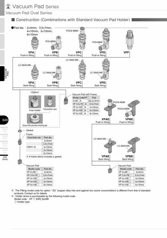
●Pad dia.:2×4mm、3.5×7mm、4×10mm、5×10mm、6×10mm
VPAPush-in fitting
VPBPush-in fitting
VPCPush-in fitting
VPDPush-in fitting
VPABarb fitting
VPBBarb fitting
VPCBarb fitting
VPDBarb fitting
VPF
Model codeVP 2×4E□VP 3.5×7E□VP 4×10E□VP 5×10E□VP 6×10E□
Pad dia.2×4mm
3.5×7mm4×10mm5×10mm6×10mm
Vacuum Pad
Frame Model code
FSPH 10
Pad dia.2×4mm
3.5×7mm4×10mm5×10mm6×10mm
Model codeVP 2×4E□VP 3.5×7E□VP 4×10E□VP 5×10E□VP 6×10E□
Pad dia.2×4mm
3.5×7mm4×10mm5×10mm6×10mm
Gasket
Frame
Vacuum Pad
VPAEPush-in fitting
VPBEPush-in fitting
VPAEBarb fitting
VPBEBarb fitting
Model codeVP 2×4E□AVP 3.5×7E□AVP 4×10E□AVP 5×10E□AVP 6×10E□A
Pad dia.2×4mm3.5×7mm4×10mm5×10mm6×10mm
Vacuum Pad with Frame
PC6-M6M PC6-M6M
POC6-M6M
LC-0640-M6
LC-0640-M6
LC-0640-M6
LC-0640-M6
POC6-M5M
POC6-M5M
LC-0640-M5
LC-0640-M5
※ A frame above includes a gasket.
(Option)(Option)
Free holderFree holder Fall prevention valveFall prevention valve
Vacuum filter pad direct mounting typeVacuum filter pad direct mounting type
■ Construction (Combinations with Standard Vacuum Pad Holder)
※ . The Fitting model code for option “-S3” (copper alloy free and against low ozone concentration) is different from that of standard products. Contact us for details.
※ . Holder alone is purchasable by the following model code. Model code:VP ① 20R( )6J/6B ① Holder type
650
VACUUM
PAD
SoftSeries
Soft BellowsSeries
SkidproofSeries
UltrathinSeries
FlatSeries
Long StrokeSeries
VacuumCylinder
AirPincette
Mark-freeSeries
OvalSeries
http://en.pisco.co.jp
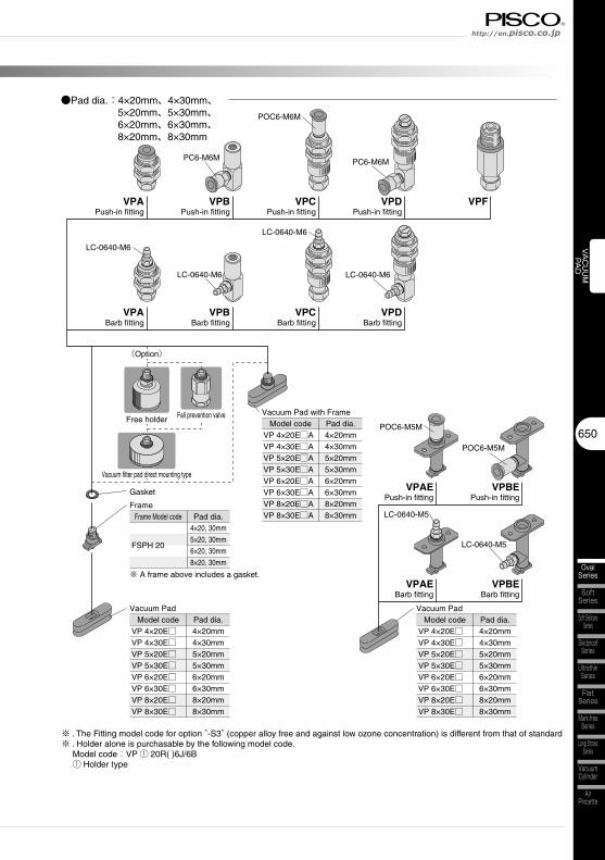
●Pad dia.:4×20mm、4×30mm、5×20mm、5×30mm、6×20mm、6×30mm、8×20mm、8×30mm
VPAPush-in fitting
VPBPush-in fitting
VPCPush-in fitting
VPDPush-in fitting
VPABarb fitting
VPBBarb fitting
VPCBarb fitting
VPDBarb fitting
VPF
Vacuum Pad
Frame Model code
FSPH 20
Pad dia.4×20, 30mm5×20, 30mm6×20, 30mm8×20, 30mm
Gasket
Frame
Vacuum Pad
VPAEPush-in fitting
VPBEPush-in fitting
VPAEBarb fitting
VPBEBarb fitting
Model codeVP 4×20E□AVP 4×30E□AVP 5×20E□AVP 5×30E□AVP 6×20E□AVP 6×30E□AVP 8×20E□AVP 8×30E□A
Pad dia.4×20mm4×30mm5×20mm5×30mm6×20mm6×30mm8×20mm8×30mm
Model codeVP 4×20E□VP 4×30E□VP 5×20E□VP 5×30E□VP 6×20E□VP 6×30E□VP 8×20E□VP 8×30E□
Pad dia.4×20mm4×30mm5×20mm5×30mm6×20mm6×30mm8×20mm8×30mm
Model codeVP 4×20E□VP 4×30E□VP 5×20E□VP 5×30E□VP 6×20E□VP 6×30E□VP 8×20E□VP 8×30E□
Pad dia.4×20mm4×30mm5×20mm5×30mm6×20mm6×30mm8×20mm8×30mm
Vacuum Pad with Frame
PC6-M6M PC6-M6M
POC6-M6M
LC-0640-M6
LC-0640-M6
LC-0640-M6
LC-0640-M6
POC6-M5M
POC6-M5M
LC-0640-M5
LC-0640-M5
※ A frame above includes a gasket.
(Option)(Option)
Free holderFree holder Fall prevention valveFall prevention valve
Vacuum filter pad direct mounting typeVacuum filter pad direct mounting type
※ . The Fitting model code for option “-S3” (copper alloy free and against low ozone concentration) is different from that of standard ※ . Holder alone is purchasable by the following model code. Model code:VP ① 20R( )6J/6B ① Holder type
651
Vacuum Pad SeriesVacuum Pad Oval Series
VACUUM
PAD
OvalSeries
Multi-BellowsSeries
SpongeSeries
StandardSeries
BellowsSeries
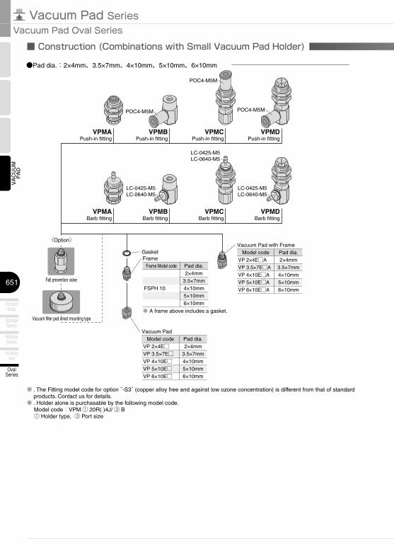
●Pad dia.:2×4mm、3.5×7mm、4×10mm、5×10mm、6×10mm
VPMAPush-in fitting
VPMBPush-in fitting
VPMCPush-in fitting
VPMDPush-in fitting
VPMABarb fitting
VPMBBarb fitting
VPMCBarb fitting
VPMDBarb fitting
POC4-M5M
POC4-M5M
POC4-M5M
LC-0425-M5LC-0640-M5
LC-0425-M5LC-0640-M5
LC-0425-M5LC-0640-M5
Frame Model code
FSPH 10
Pad dia.2×4mm
3.5×7mm4×10mm5×10mm6×10mm
Model codeVP 2×4E□VP 3.5×7E□VP 4×10E□VP 5×10E□VP 6×10E□
Pad dia.2×4mm
3.5×7mm4×10mm5×10mm6×10mm
GasketFrame
Vacuum Pad
Model codeVP 2×4E□AVP 3.5×7E□AVP 4×10E□AVP 5×10E□AVP 6×10E□A
Pad dia.2×4mm
3.5×7mm4×10mm5×10mm6×10mm
Vacuum Pad with Frame
※ A frame above includes a gasket.
(Option)(Option)
Fall prevention valveFall prevention valve
Vacuum filter pad direct mounting typeVacuum filter pad direct mounting type
■ Construction (Combinations with Small Vacuum Pad Holder)
※ . The Fitting model code for option “-S3” (copper alloy free and against low ozone concentration) is different from that of standard products. Contact us for details.
※ . Holder alone is purchasable by the following model code. Model code:VPM ① 20R( )4J/ ③ B ① Holder type, ③ Port size
652
VACUUM
PAD
SoftSeries
Soft BellowsSeries
SkidproofSeries
UltrathinSeries
FlatSeries
Long StrokeSeries
VacuumCylinder
AirPincette
Mark-freeSeries
OvalSeries
http://en.pisco.co.jp
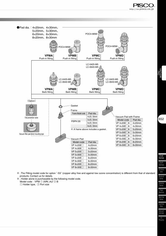
●Pad dia.:4×20mm、4×30mm、5×20mm、5×30mm、6×20mm、6×30mm、8×20mm、8×30mm
VPMAPush-in fitting
VPMBPush-in fitting
VPMCPush-in fitting
VPMDPush-in fitting
VPMABarb fitting
VPMBBarb fitting
VPMCBarb fitting
VPMDBarb fitting
POC4-M5M
POC4-M5M
POC4-M5M
LC-0425-M5LC-0640-M5
LC-0425-M5LC-0640-M5
LC-0425-M5LC-0640-M5
Frame Model code
FSPH 20
Pad dia.4×20, 30mm5×20, 30mm6×20, 30mm8×20, 30mm
Gasket
Frame
※ A frame above includes a gasket.
Vacuum Pad
Model codeVP 4×20E□AVP 4×30E□AVP 5×20E□AVP 5×30E□AVP 6×20E□AVP 6×30E□AVP 8×20E□AVP 8×30E□A
Pad dia.4×20mm4×30mm5×20mm5×30mm6×20mm6×30mm8×20mm8×30mm
Model codeVP 4×20E□VP 4×30E□VP 5×20E□VP 5×30E□VP 6×20E□VP 6×30E□VP 8×20E□VP 8×30E□
Pad dia.4×20mm4×30mm5×20mm5×30mm6×20mm6×30mm8×20mm8×30mm
Vacuum Pad with Frame
(Option)(Option)
Fall prevention valveFall prevention valve
Vacuum filter pad direct mounting typeVacuum filter pad direct mounting type
※ . The Fitting model code for option “-S3” (copper alloy free and against low ozone concentration) is different from that of standard products. Contact us for details.
※ . Holder alone is purchasable by the following model code. Model code:VPM ① 20R( )4J/ ③ B ① Holder type, ③ Port size

653
Vacuum Pad SeriesVacuum Pad Oval Series
VACUUM
PAD
OvalSeries
Multi-BellowsSeries
SpongeSeries
StandardSeries
BellowsSeries
Vacuum Pad SeriesVacuum Pad
477
VACUUM
PAD
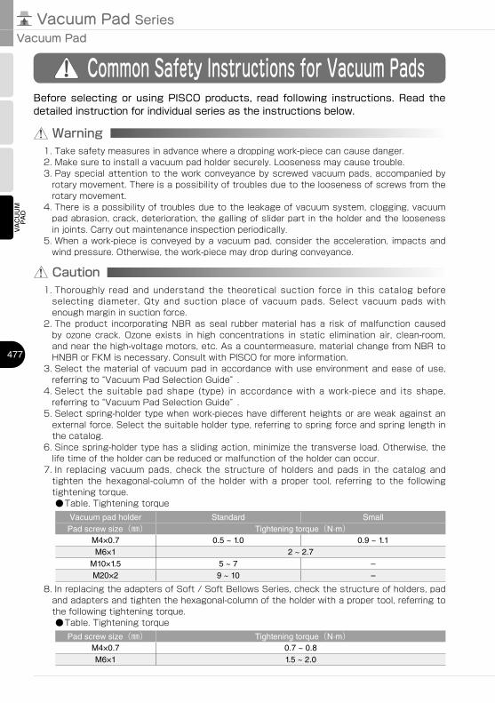
Common Safety Instructions for Vacuum Pads
Warning
Before selecting or using PISCO products, read following instructions. Read the detailed instruction for individual series as the instructions below.
1. Take safety measures in advance where a dropping work-piece can cause danger.2. Make sure to install a vacuum pad holder securely. Looseness may cause trouble.3. Pay special attention to the work conveyance by screwed vacuum pads, accompanied by
rotary movement. There is a possibility of troubles due to the looseness of screws from the rotary movement.
4. There is a possibility of troubles due to the leakage of vacuum system, clogging, vacuum pad abrasion, crack, deterioration, the galling of slider part in the holder and the looseness in joints. Carry out maintenance inspection periodically.
5. When a work-piece is conveyed by a vacuum pad, consider the acceleration, impacts and wind pressure. Otherwise, the work-piece may drop during conveyance.
Caution1. Thoroughly read and understand the theoretical suction force in this catalog before
selecting diameter, Qty and suction place of vacuum pads. Select vacuum pads with enough margin in suction force.
2. The product incorporating NBR as seal rubber material has a risk of malfunction caused by ozone crack. Ozone exists in high concentrations in static elimination air, clean-room, and near the high-voltage motors, etc. As a countermeasure, material change from NBR to HNBR or FKM is necessary. Consult with PISCO for more information.
3. Select the material of vacuum pad in accordance with use environment and ease of use, referring to “Vacuum Pad Selection Guide” .
4. Select the suitable pad shape (type) in accordance with a work-piece and its shape, referring to “Vacuum Pad Selection Guide” .
5. Select spring-holder type when work-pieces have different heights or are weak against an external force. Select the suitable holder type, referring to spring force and spring length in the catalog.
6. Since spring-holder type has a sliding action, minimize the transverse load. Otherwise, the life time of the holder can be reduced or malfunction of the holder can occur.
7. In replacing vacuum pads, check the structure of holders and pads in the catalog and tighten the hexagonal-column of the holder with a proper tool, referring to the following tightening torque.●Table. Tightening torque
Vacuum pad holder Standard SmallPad screw size(㎜) Tightening torque(N·m)
M4×0.7 0.5 ~ 1.0 0.9 ~ 1.1M6×1 2 ~ 2.7
M10×1.5 5 ~ 7 –M20×2 9 ~ 10 –
8. In replacing the adapters of Soft / Soft Bellows Series, check the structure of holders, pad and adapters and tighten the hexagonal-column of the holder with a proper tool, referring to the following tightening torque.●Table. Tightening torque
Pad screw size(㎜) Tightening torque(N·m)M4×0.7 0.7 ~ 0.8M6×1 1.5 ~ 2.0
478
VACUUM
PAD
VACUUM
ACCESSARIES
StandardSeries
SpongeSeries
BellowsSeries
Multi-BellowsSeries
SoftSeries
Soft BellowsSeries
SkidproofSeries
UltrathinSeries
FlatSeries
Long StrokeSeries
VacuumCylinder
AirPincette
OvalSeries
Mark-freeSeries
http://en.pisco.co.jp
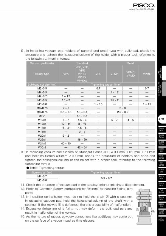
9 . In installing vacuum pad holders of general and small type with bulkhead, check the structure and tighten the hexagonal-column of the holder with a proper tool, referring to the following tightening torque.
Vacuum pad holder Standard Small
Holder type VPA
VPC, VPD,VPF,
VPHC,VPHD,
VPHDW
VPE VPMAVPMC,VPMD
VPME
Bulkhead nut size(㎜) Tightening torque(N·m)M3×0.5 — — 0.7 — — 0.7M4×0.5 — — — 1 ~ 1.2 — —M4×0.7 1 ~ 1.2 — — — — —M5×0.5 1.5 ~ 2 — — 1.5 ~ 2 — —M5×0.8 — — 1 ~ 1.5 — — 1 ~ 1.5
M6×0.75 2 ~ 3 — — 2 ~ 3 —M8×0.75 2.5 ~ 3.5 1.8 ~ 2.4 — 2.5 ~ 3.5 —
M8×1 — 1.8 ~ 2.4 — — — —M10×1 5 ~ 7 4.5 ~ 6 — 5 ~ 7 4 ~ 6 —M12×1 12 ~ 14 8 ~ 10 — — — —M14×1 18 ~ 21 4.5 ~ 6 — — — —M16×1 — 2 ~ 3 — — — —M20×1 19 ~ 21 — — — — —M22×1 — 16 ~ 20 — — — —M24×2 40 ~ 50 — — — — —M30×2 — 42 ~ 54 — — — —
10. In replacing vacuum pad rubbers of Standard Series ø80, ø100mm, ø150mm, ø200mm and Bellows Series ø80mm, ø100mm, check the structure of holders and pads and tighten the hexagonal-column of the holder with a proper tool, referring to the following tightening torque.●Table. Tightening torque
Screw size(㎜) Tightening torque(N·m)M4×0.7
0.5 ~ 0.7M5×0.8
11. Check the structure of vacuum pad in the catalog before replacing a filter element.12. Refer to “Common Safety Instructions for Fittings” for handing fitting joint
parts.13. In installing spring-holder type, do not hold the shaft A with a spanner.
In replacing vacuum pad, hold the hexagonal-column of the shaft with a spanner. If the keyway B is deformed, there is a possibility of malfunction.
14. Excessive tightening of a fixing nut may deform the bulkhead part and result in malfunction of the keyway.
15. As the nature of rubber, powdery component like additives may come out on the surface of a vacuum pad as time elapses.
B }A
Vacuum Pad SeriesVacuum Pad
479
VACUUM
PAD
0
4
2
0
10
18
16
14
12
8
6
20
20 40 60 80 100
ø15
ø10
ø6
ø8
Vacuum level(–kPa)
The
oret
ical
suc
tion
forc
e(N)
Pad
dia
.(m
m)
ø4ø3ø2
0
500
0
1000
2000
3500
3000
1500
2500
20 40 60 80 100
ø200
ø150
ø100
ø80
ø60
Vacuum level(–kPa)
The
oret
ical
suc
tion
forc
e(N)
Pad
dia
.(m
m)
0
100
50
0
150
200
250
20 40 60 80 100
ø50
ø40
ø30
ø25
ø20
Vacuum level(–kPa)
The
oret
ical
suc
tion
forc
e(N)
Pad
dia
.(m
m)
Pad dia.:ø2mm ~ ø15mm Pad dia.:ø20mm ~ ø50mm
Pad dia.:ø60mm ~ ø200mm
0
0.2
0
0.4
0.8
1.4
1.2
0.6
1.0
20 40 60 80 100
ø3
ø4
ø2
ø1.5
ø1ø0.7
Vacuum level(–kPa)
The
oret
ical
suc
tion
forc
e(N)
Pad
dia
.(m
m)
Pad dia.(small):ø0.7mm ~ ø4mm
Vacuum Pad Selection GuideSelection Guide 1
▲
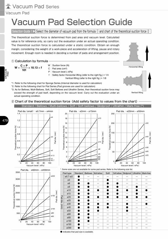
Select the diameter of vacuum pad from the formula ① and chart of the theoretical suction force ②The theoretical suction force is determined from pad area and vacuum level. Calculated value is for reference only, so carry out the evaluation under an actual operating condition. The theoretical suction force is calculated under a static condition. Obtain an enough margin, considering the weight of a work-piece and acceleration of lifting, pause and rotary movement. Enough room is needed in deciding a number of pads and arrangement position.
① Calculation by formula
W = C × P
× 10.13 × f −
101
*1. Refer to the following chart for Sponge Series.(Internal diameter is used for calculation)*2. Refer to the following chart for Flat Series.(Pad grooves are used for calculation)*3. As for Bellows, Multi-Bellows, Soft, Soft Bellows and Ultrathin Series, their theoretical suction force may
exceed the strength of pad itself, depending on the vacuum level. Carry out the evaluation under an actual operating condition.
Horizontal lifting
Vertical lifting
W :Suction force (N) C : Pad area (cm²) P : Vacuum level (−kPa) f : Safety factor Horizontal lifting (refer to the right fig.)
▲
1/4Vertical lifting (refer to the right fig.)
▲
1/8
② Chart of the theoretical suction force〈Add safety factor to values from the chart〉Standard / Bellows / Multi-bellows / Soft / Soft bellows / Skidproof / Ultrathin / Mark-free (*)
*. Some sizes are not available for some pad series. Refer to the following size list.
Pad type Standard Bellows Multi-bellows Soft Soft bellows Skidproof Ultrathin Mark-free
Pad dia. (m
m)
ø0.7~ø3 ● ー ー ー ー ー ー ーø4 ● ー ー ● ー ー ー ーø6 ● ● ー ● ● ー ー ーø8 ● ● ー ● ● ー ● ーø10 ● ● ● ● ● ● ● ●ø15 ● ● ー ● ● ー ● ーø20 ● ● ● ● ● ● ● ●ø25 ● ● ー ー ー ー ー ーø30 ● ● ● ● ー ● ー ●ø40 ● ● ● ● ー ● ー ーø50 ● ● ● ー ー ● ー ーø60 ● ● ー ー ー ー ー ーø80 ● ● ー ー ー ー ー ーø100 ● ● ー ー ー ー ー ーø150 ● ー ー ー ー ー ー ーø200 ● ー ー ー ー ー ー ー
● indicates that pad size is available.
480
VACUUM
PAD
VACUUM
ACCESSARIES
StandardSeries
SpongeSeries
BellowsSeries
Multi-BellowsSeries
SoftSeries
Soft BellowsSeries
SkidproofSeries
UltrathinSeries
FlatSeries
Long StrokeSeries
VacuumCylinder
AirPincette
OvalSeries
Mark-freeSeries
http://en.pisco.co.jp
0
300
250
200
150
100
50
0
350
400
450
20 40 60 80 100
ø100
ø50
ø70
ø10ø15ø20
ø30 ø25ø35
Vacuum level(–kPa)
The
oret
ical
suc
tion
forc
e(N)
Pad
dia
.(m
m)
パッド径:ø10mm ~ ø100mm
0
8
4
0
12
16
20
6
2
10
14
18
20 40 60 80 100
ø30
ø25
ø20
ø15
ø10
Vacuum level(–kPa)
The
oret
ical
suc
tion
forc
e(N)
Pad
dia
.(m
m)
0
15
10
5
0
25
20
20 40 60 80 100
8×30
6×30
5×30,8×20
4×306×20
5×20
4×20
6×10
Vacuum level(–kPa)
The
oret
ical
suc
tion
forc
e(N)
Pad
siz
e(m
m)
4×103.5×7
2×4
Pad size:2×4mm, 3.5×7mm,□×10mm, □×20mm, □×30mm
5×10
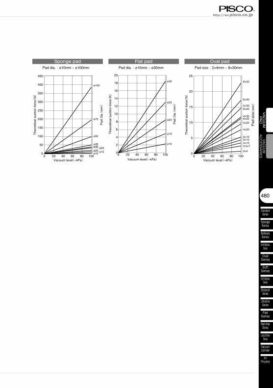
Sponge pad Flat pad Oval padPad dia.:ø10mm ~ ø30mmPad dia.:ø10mm ~ ø100mm Pad size:2×4mm ~ 8×30mm
Vacuum Pad SeriesVacuum Pad
481
VACUUM
PAD
ød
øS
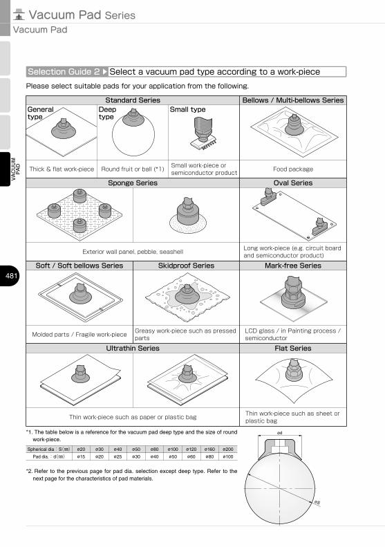
Selection Guide 2
▲
Select a vacuum pad type according to a work-piecePlease select suitable pads for your application from the following.
Standard Series Bellows / Multi-bellows Series
Ultrathin Series
Skidproof Series
Thick & flat work-piece Round fruit or ball (*1)
Oval Series
Soft / Soft bellows Series
Food package
Long work-piece (e.g. circuit board and semiconductor product)
Molded parts / Fragile work-piece Greasy work-piece such as pressed parts
Thin work-piece such as paper or plastic bag
General type
Deep type
*1. The table below is a reference for the vacuum pad deep type and the size of round work-piece.
Spherical dia:S(㎜) ø20 ø30 ø40 ø50 ø80 ø100 ø120 ø160 ø200
Pad dia.:d(㎜) ø15 ø20 ø25 ø30 ø40 ø50 ø60 ø80 ø100
*2. Refer to the previous page for pad dia. selection except deep type. Refer to the next page for the characteristics of pad materials.
Sponge Series
Exterior wall panel, pebble, seashell
Mark-free Series
Flat Series
LCD glass / in Painting process / semiconductor
Thin work-piece such as sheet or plastic bag
Small work-piece or semiconductor product
Small type

482
VACUUM
PAD
VACUUM
ACCESSARIES
StandardSeries
SpongeSeries
BellowsSeries
Multi-BellowsSeries
SoftSeries
Soft BellowsSeries
SkidproofSeries
UltrathinSeries
FlatSeries
Long StrokeSeries
VacuumCylinder
AirPincette
OvalSeries
Mark-freeSeries
http://en.pisco.co.jp
Selection Guide 3
▲
Select a vacuum pad material from an applicationPlease select the suitable material from the table.
Legend ◎:Best○:Suitable△:Good×:NG
*1. Material code “NH” is only applicable to Skidproof Series.*2. It does not apply to pad size: 4×30mm.Note 1) The above “Physical Properties” shows the data of general synthetic rubbers.Note 2) The highest / lowest operating temp. are for momentary usage. Carry out durability evaluation in case of continuous usage
under the highest / lowest operating temp.
Item
Pad materialNitrile
rubber
NBR Suited
for the food
sanitation
act. (Japan)
HNBRSilicone
rubber
Conductive
Silicone
rubber
Urethane
rubber
Fluoro
rubber
Fluorosilicone
rubberEPDM
Conductive
Butadiene
rubber (Low
resistance
type)
Conductive
NBR (low
resistance)
Chloroprene
rubber (For
Sponge
type)
Silicone
rubber
(For
Sponge
Type)
Material codeN,
NH(*1)G HN S SE U F FS EP E NE – S
Application
Cardboard
Plywood
Metal plate
Food-related
Other general
work
Cardboard
Plywood
Metal plate
Food-related
Other
general work
In use under
a low ozone
concentration
environment
Semiconductors
Taking out
molded parts
Thin work-piece
Food-related
Cardboard
Plywood
Metal
plate
Chemical
environment
High temp.
work-pieces
Taking out
molded
parts
Application
that requires
light-resistant
or ozone-
proof In use
under in the
moisture-
containing
atmosphere
General
parts of
semiconductors
Semiconductors Uneven
work-
piece
Uneven
work-
piece
Food-
related
Pad color Black Gray Black Translucent Black Blue Gray Salmon Black Black Black Black Salmon
Physical P
roperties
Surface
hardness
(Shore A)
Standard 50˚~80˚ 60˚~70˚ 50˚~70˚ 50˚ 60˚ 55˚~70˚ 60˚~70˚ - 50˚~70˚ 70˚ 60˚~70˚ - -Bellows 50˚ - 50˚ 50˚ 60˚ 55˚ 60˚ - 50˚ - 60˚ - -Multi-bellows 50˚ 50˚ 50˚ 50˚ - 55˚ 50˚ - 50˚ - 60˚ - -Oval 40˚~50˚ - 50˚ 40˚~50˚ 50˚~60˚ 55(̊*2)50(̊*2) - 50˚ 70˚ 70˚ - -Soft 40˚ - - 40˚ 60˚ - - 40˚ - - 50˚ - -Soft bellows 40˚ - 50˚ 40˚ - 55˚ - - 50˚ - 60˚ - -Skidproof 50˚ - - 50˚ - 55˚ 60˚ - - - 60˚ - -Ultrathin 40˚ - - 40˚ - 55˚ 50˚ 40˚ - - 60˚ - -Flat 60˚ - - 40˚ 40˚ 50˚ 50˚ - - - 60˚ - -
Highest operating temp. 110˚C 140˚C 180˚C 60˚C 230˚C 180˚C 150˚C 100˚C 110˚C 80˚C 180˚C
Lowest operating temp. -30˚C -30˚C -40˚C -20˚C -10˚C -50˚C -40˚C -50˚C -30˚C -45˚C -40˚C
Weatherability △ ○ ◎ ○ ○ ○ ◎ ○ △ ○ ◎Ozone-proof × ○ ◎ ◎ ◎ ◎ ◎ × × ○ ◎Acid-resistance △ △ ○ × ◎ ○ ◎ △ △ △ ○Alkaline-resistance ○ ○ ◎ × × ◎ ◎ ○ ○ ◎ ◎Oil
resistance
(Gasoline oil) ◎ ◎ △ ◎ ◎ △ × × ◎ × △(Benzene/toluene) △ × △ △ ◎ △ × × △ △ △
Volume resistance - - - Max.105Ω·cm - - - - Max.200Ω·cm Max.200Ω·cm - -
Vacuum Pad SeriesVacuum Pad
483
VACUUM
PAD
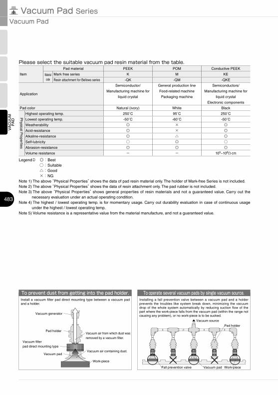
To prevent dust from getting into the pad holder.Install a vacuum filter pad direct mounting type between a vacuum pad and a holder.
Work-piece
Vacuum air containing dust.
Vacuum air from which dust was removed by a vacuum filter.
Vacuum pad
Pad holder
Vacuum filterpad direct mounting type
Vacuum generator
To operate several vacuum pads by single vacuum source.Installing a fall prevention valve between a vacuum pad and a holder prevents the troubles like system break down, minimizing the vacuum drop of the whole system automatically by reducing suction flow of the part where the work-piece falls from the vacuum pad (within the range not causing any problem), or no work-piece is to be sucked.
Fall prevention valve
Pad holder
Vacuum pad Work-piece
Please select the suitable vacuum pad resin material from the table.
Legend ◎:Best○:Suitable△:Good×:NG
Note 1) The above “Physical Properties” shows the data of pad resin material only. The holder of Mark-free Series is not included.Note 2) The above “Physical Properties” shows the data of resin attachment only. The pad rubber is not included.Note 3) The above “Physical Properties” shows general properties of resin materials and not a guaranteed value. Carry out the
necessary evaluation under an actual operating condition.Note 4) The highest / lowest operating temp. is for momentary usage. Carry out durability evaluation in case of continuous usage
under the highest / lowest operating temp.Note 5) Volume resistance is a representative value from the material manufacture, and not a guaranteed value.
Item
Pad material PEEK POM Conductive PEEK
Material code
Mark free series K M KE
Resin attachment for Bellows series -QK -QM -QKE
Application
Semiconductor/
Manufacturing machine for
liquid crystal
General production line
Food-related machine
Packaging machine
Semiconductors/
Manufacturing machine for
liquid crystal
Electronic components
Pad color Natural (ivory) White Black
Physical P
roperties
Highest operating temp. 250˚C 95˚C 250˚C
Lowest operating temp. -50˚C -60˚C -50˚C
Weatherability ◎ × ◎Acid-resistance ◎ × ◎Alkaline-resistance ◎ △ ◎Self-lubricity ○ ◎ ○Abrasion-resistance ◎ ◎ ◎Volume resistance - - 105~106Ω·cm
○ × ○ × ○
▲ Vacuum source
15°
484
VACUUM
PAD
VACUUM
ACCESSARIES
StandardSeries
SpongeSeries
BellowsSeries
Multi-BellowsSeries
SoftSeries
Soft BellowsSeries
SkidproofSeries
UltrathinSeries
FlatSeries
Long StrokeSeries
VacuumCylinder
AirPincette
OvalSeries
Mark-freeSeries
http://en.pisco.co.jp
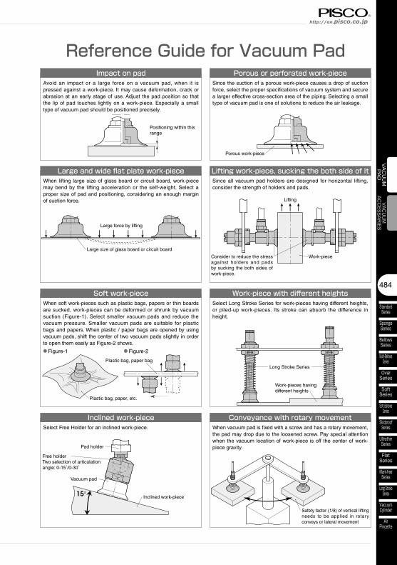
Reference Guide for Vacuum PadImpact on pad
Avoid an impact or a large force on a vacuum pad, when it is pressed against a work-piece. It may cause deformation, crack or abrasion at an early stage of use. Adjust the pad position so that the lip of pad touches lightly on a work-piece. Especially a small type of vacuum pad should be positioned precisely.
Porous or perforated work-pieceSince the suction of a porous work-piece causes a drop of suction force, select the proper specifications of vacuum system and secure a larger effective cross-section area of the piping. Selecting a small type of vacuum pad is one of solutions to reduce the air leakage.
Large and wide flat plate work-pieceWhen lifting large size of glass board or circuit board, work-piece may bend by the lifting acceleration or the self-weight. Select a proper size of pad and positioning, considering an enough margin of suction force.
Soft work-piece Work-piece with different heightsSelect Long Stroke Series for work-pieces having different heights, or piled-up work-pieces. Its stroke can absorb the difference in height.
Inclined work-pieceSelect Free Holder for an inclined work-piece.
Positioning within this range
Porous work-piece
Plastic bag, paper, etc.
Large size of glass board or circuit board
Inclined work-piece
Work-pieces having different heights
Large force by lifting
Plastic bag, paper bag
● Figure-1 ● Figure-2
Long Stroke Series
Free holderTwo selection of articulation angle: 0-15°/0-30°
Lifting work-piece, sucking the both side of itSince all vacuum pad holders are designed for horizontal lifting, consider the strength of holders and pads.
Work-piece
Lifting
Consider to reduce the stress against holders and pads by sucking the both sides of work-piece.
Vacuum pad
Pad holder
Conveyance with rotary movementWhen vacuum pad is fixed with a screw and has a rotary movement, the pad may drop due to the loosened screw. Pay special attention when the vacuum location of work-piece is off the center of work-piece gravity.
Safety factor (1/8) of vertical lifting needs to be applied in rotary conveys or lateral movement
When soft work-pieces such as plastic bags, papers or thin boards are sucked, work-pieces can be deformed or shrunk by vacuum suction (Figure-1). Select smaller vacuum pads and reduce the vacuum pressure. Smaller vacuum pads are suitable for plastic bags and papers. When plastic / paper bags are opened by using vacuum pads, shift the center of two vacuum pads slightly in order to open them easily as Figure-2 shows.
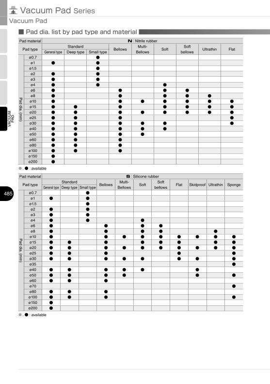
■ Pad dia. list by pad type and material
Vacuum Pad SeriesVacuum Pad
485
VACUUM
PAD
Pad material N:Nitrile rubber
Pad typeStandard
BellowsMulti-
BellowsSoft
Soft bellows
Ultrathin FlatGeneral type Deep type Small type
Pad dia. (m
m)
ø0.7 ●ø1 ● ●
ø1.5 ●ø2 ● ●ø3 ● ●ø4 ● ● ●ø6 ● ● ● ●ø8 ● ● ● ● ●ø10 ● ● ● ● ● ● ●ø15 ● ● ● ● ● ● ●ø20 ● ● ● ● ● ● ● ●ø25 ● ● ● ●ø30 ● ● ● ● ● ●ø40 ● ● ● ● ●ø50 ● ● ● ●ø60 ● ● ●ø80 ● ● ●ø100 ● ● ●ø150 ●ø200 ●
※ . ● : available
Pad material S:Silicone rubber
Pad typeStandard
BellowsMulti-
BellowsSoft
Soft bellows
Flat Skidproof Ultrathin SpongeGeneral type Deep type Small type
Pad dia. (m
m)
ø0.7 ●ø1 ● ●
ø1.5 ●ø2 ● ●ø3 ● ●ø4 ● ● ●ø6 ● ● ● ●ø8 ● ● ● ● ●ø10 ● ● ● ● ● ● ● ● ●ø15 ● ● ● ● ● ● ● ●ø20 ● ● ● ● ● ● ● ● ● ●ø25 ● ● ● ● ●ø30 ● ● ● ● ● ● ● ●ø35 ●ø40 ● ● ● ● ● ●ø50 ● ● ● ● ● ●ø60 ● ● ●ø70 ●ø80 ● ● ●ø100 ● ● ● ●ø150 ●ø200 ●
※ . ● : available
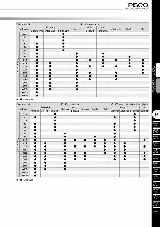
486
VACUUM
PAD
VACUUM
ACCESSARIES
StandardSeries
SpongeSeries
BellowsSeries
Multi-BellowsSeries
SoftSeries
Soft BellowsSeries
SkidproofSeries
UltrathinSeries
FlatSeries
Long StrokeSeries
VacuumCylinder
AirPincette
OvalSeries
Mark-freeSeries
http://en.pisco.co.jp
Pad material U:Urethane rubber
Pad typeStandard
BellowsMulti-
BellowsSoft
bellowsSkidproof Ultrathin Flat
General type Deep type Small type
Pad dia. (m
m)
ø0.7 ●ø1 ● ●
ø1.5 ●ø2 ● ●ø3 ● ●ø4 ● ●ø6 ● ● ●ø8 ● ● ● ●ø10 ● ● ● ● ● ● ●ø15 ● ● ● ● ● ●ø20 ● ● ● ● ● ● ● ●ø25 ● ● ● ●ø30 ● ● ● ● ● ●ø40 ● ● ● ● ●ø50 ● ● ● ● ●ø60 ● ● ●ø80 ● ● ●ø100 ● ● ●ø150 ●ø200 ●
※ . ● : available
Pad material F:Fluoro rubber G:NBR Suited for the food sanitation act. (Japan)
Pad typeStandard
BellowsMulti-
BellowsSkidproof Ultrathin Flat
Standard Multi-BellowsGeneral type Deep type Small type General type Deep type Small type
Pad dia. (m
m)
ø0.7 ● ●ø1 ● ● ● ●
ø1.5 ● ●ø2 ● ● ● ●ø3 ● ● ● ●ø4 ● ● ● ●ø6 ● ● ●ø8 ● ● ● ●ø10 ● ● ● ● ● ● ● ●ø15 ● ● ● ● ● ● ●ø20 ● ● ● ● ● ● ● ● ● ●ø25 ● ● ● ● ● ●ø30 ● ● ● ● ● ● ● ● ●ø40 ● ● ● ● ● ● ● ●ø50 ● ● ● ● ● ● ● ●ø60 ● ● ●ø80 ● ● ●ø100 ● ● ●ø150 ●ø200 ●
※ . ● : available
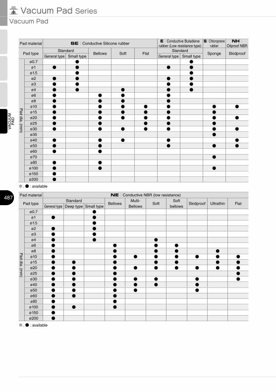
Vacuum Pad SeriesVacuum Pad
487
VACUUM
PAD
Pad material SE:Conductive Silicone rubberE:Conductive Butadiene
rubber (Low resistance type)S:Chloroprene
rubberNH:
Oilproof NBR
Pad typeStandard
Bellows Soft FlatStandard
Sponge SkidproofGeneral type Small type General type Small type
Pad dia. (m
m)
ø0.7 ● ●ø1 ● ● ● ●
ø1.5 ● ●ø2 ● ● ● ●ø3 ● ● ● ●ø4 ● ● ● ● ●ø6 ● ● ● ●ø8 ● ● ● ●ø10 ● ● ● ● ● ● ●ø15 ● ● ● ● ● ●ø20 ● ● ● ● ● ● ●ø25 ● ● ● ● ●ø30 ● ● ● ● ● ● ●ø35 ●ø40 ● ● ● ● ●ø50 ● ● ● ● ●ø60 ● ●ø70 ●ø80 ● ●
ø100 ● ● ●ø150 ●ø200 ●
※ . ● : available
Pad material NE:Conductive NBR (low resistance)
Pad typeStandard
BellowsMulti-
BellowsSoft
Soft bellows
Skidproof Ultrathin FlatGeneral type Deep type Small type
Pad dia. (m
m)
ø0.7 ●ø1 ● ●
ø1.5 ●ø2 ● ●ø3 ● ●ø4 ● ● ●ø6 ● ● ● ●ø8 ● ● ● ● ●ø10 ● ● ● ● ● ● ● ●ø15 ● ● ● ● ● ● ●ø20 ● ● ● ● ● ● ● ● ●ø25 ● ● ● ●ø30 ● ● ● ● ● ● ●ø40 ● ● ● ● ● ●ø50 ● ● ● ● ●ø60 ● ● ●ø80 ● ●
ø100 ● ● ●ø150 ●ø200 ●
※ . ● : available
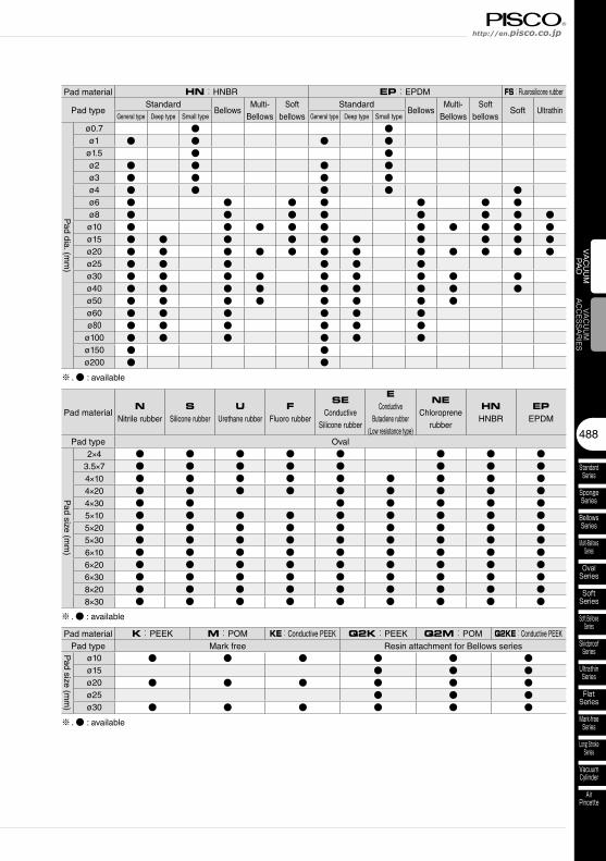
488
VACUUM
PAD
VACUUM
ACCESSARIES
StandardSeries
SpongeSeries
BellowsSeries
Multi-BellowsSeries
SoftSeries
Soft BellowsSeries
SkidproofSeries
UltrathinSeries
FlatSeries
Long StrokeSeries
VacuumCylinder
AirPincette
OvalSeries
Mark-freeSeries
http://en.pisco.co.jp
Pad material HN:HNBR EP:EPDM FS:Fluorosilicone rubber
Pad typeStandard
BellowsMulti-
BellowsSoft
bellowsStandard
BellowsMulti-
BellowsSoft
bellowsSoft Ultrathin
General type Deep type Small type General type Deep type Small type
Pad dia. (m
m)
ø0.7 ● ●ø1 ● ● ● ●
ø1.5 ● ●ø2 ● ● ● ●ø3 ● ● ● ●ø4 ● ● ● ● ●ø6 ● ● ● ● ● ● ●ø8 ● ● ● ● ● ● ● ●ø10 ● ● ● ● ● ● ● ● ● ●ø15 ● ● ● ● ● ● ● ● ● ●ø20 ● ● ● ● ● ● ● ● ● ● ● ●ø25 ● ● ● ● ● ●ø30 ● ● ● ● ● ● ● ● ●ø40 ● ● ● ● ● ● ● ● ●ø50 ● ● ● ● ● ● ● ●ø60 ● ● ● ● ● ●ø80 ● ● ● ● ● ●
ø100 ● ● ● ● ● ●ø150 ● ●ø200 ● ●
※ . ● : available
Pad materialN
Nitrile rubberS
Silicone rubberU
Urethane rubberF
Fluoro rubber
SEConductive
Silicone rubber
EConductive
Butadiene rubber (Low resistance type)
NEChloroprene
rubber
HNHNBR
EPEPDM
Pad type Oval
Pad size (m
m)
2×4 ● ● ● ● ● ● ● ●3.5×7 ● ● ● ● ● ● ● ●4×10 ● ● ● ● ● ● ● ● ●4×20 ● ● ● ● ● ● ● ● ●4×30 ● ● ● ● ● ● ●5×10 ● ● ● ● ● ● ● ● ●5×20 ● ● ● ● ● ● ● ● ●5×30 ● ● ● ● ● ● ● ● ●6×10 ● ● ● ● ● ● ● ● ●6×20 ● ● ● ● ● ● ● ● ●6×30 ● ● ● ● ● ● ● ● ●8×20 ● ● ● ● ● ● ● ● ●8×30 ● ● ● ● ● ● ● ● ●
※ . ● : available
Pad material K:PEEK M:POM KE:Conductive PEEK Q2K:PEEK Q2M:POM Q2KE:Conductive PEEKPad type Mark free Resin attachment for Bellows series
Pad size (m
m)
ø10 ● ● ● ● ● ●ø15 ● ● ●ø20 ● ● ● ● ● ●ø25 ● ● ●ø30 ● ● ● ● ● ●
※ . ● : available
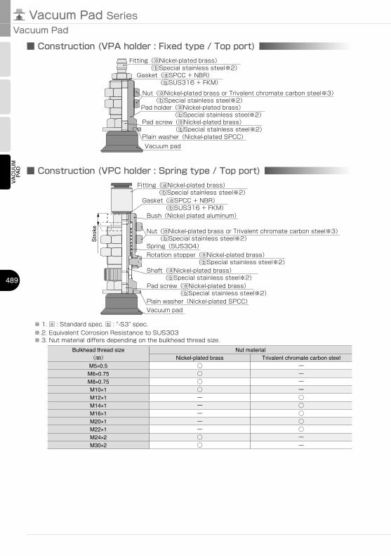
Vacuum Pad SeriesVacuum Pad
489
VACUUM
PAD
■ Construction (VPA holder : Fixed type / Top port)
Nut(aNickel-plated brass or Trivalent chromate carbon steel※3)
Pad holder(aNickel-plated brass)
Plain washer(Nickel-plated SPCC)
(bSpecial stainless steel※2)
(bSpecial stainless steel※2)
Vacuum pad
Pad screw(aNickel-plated brass)(bSpecial stainless steel※2)
Fitting(aNickel-plated brass)(bSpecial stainless steel※2)
Gasket(aSPCC + NBR)(bSUS316 + FKM)
■ Construction (VPC holder : Spring type / Top port)
Str
oke
Nut(aNickel-plated brass or Trivalent chromate carbon steel※3)(bSpecial stainless steel※2)
Bush(Nickel plated aluminum)
Plain washer(Nickel-plated SPCC)Vacuum pad
Pad screw(aNickel-plated brass)(bSpecial stainless steel※2)
Fitting(aNickel-plated brass)(bSpecial stainless steel※2)
Gasket(aSPCC + NBR)(bSUS316 + FKM)
Shaft(aNickel-plated brass)(bSpecial stainless steel※2)
Rotation stopper(aNickel-plated brass)(bSpecial stainless steel※2)
Spring(SUS304)
※ 3. Nut material differs depending on the bulkhead thread size.Bulkhead thread size
(㎜)Nut material
Nickel-plated brass Trivalent chromate carbon steelM5×0.5 ○ ーM6×0.75 ○ ーM8×0.75 ○ ーM10×1 ○ ーM12×1 ー ○M14×1 ー ○M16×1 ー ○M20×1 ー ○M22×1 ー ○M24×2 ○ ーM30×2 ○ ー
※ 1. a : Standard spec. b : “-S3” spec.※ 2. Equivalent Corrosion Resistance to SUS303
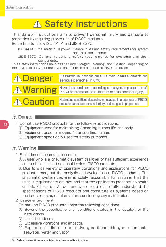
43
Safety Instructions
Warning
This Safety Instructions aim to prevent personal injury and damage to properties by requiring proper use of PISCO products.Be certain to follow ISO 4414 and JIS B 8370.
ISO 4414:Pneumatic fluid power…General rules and safety requirements for system and their components.
JIS B 8370: General rules and safety requirements for systems and their components.
This Safety instructions are classified into "Danger", "Warning" and "Caution", depending on the degree of danger or damages caused by improper use of PISCO products.
Safety Instructions
Danger Hazardous conditions. It can cause death or serious personal injury.
Warning Hazardous conditions depending on usages. Improper Use of PISCO products can case death or serious personal injury.
Caution Hazardous conditions depending on usages. Improper use of PISCO products can cause personal injury or damages to properties.
※ . Safety Instructions are subject to change without notice.
1. Selection of pneumatic products.① A user who is a pneumatic system designer or has sufficient experience
and technical expertise should select PISCO products.② Due to wide variety of operating conditions and applications for PISCO
products, carry out the analysis and evaluation on PISCO products. The pneumatic system designer is solely responsible for assuring that the user’ s requirements are met and that the application presents no health or safety hazards. All designers are required to fully understand the specifications of PISCO products and constitute all systems based on the latest catalog or information, considering any malfunction.
2. Usage environmentDo not use PISCO products under the following conditions.①. Beyond the specifications or conditions stated in the catalog, or the
instructions.②. Use at outdoors.③. Excessive vibrations and impacts.④. Exposure / adhere to corrosive gas, flammable gas, chemicals,
seawater, water and vapor.
Danger1. Do not use PISCO products for the following applications.
①. Equipment used for maintaining / handling human life and body.②. Equipment used for moving / transporting human.③. Equipment specifically used for safety purposes.
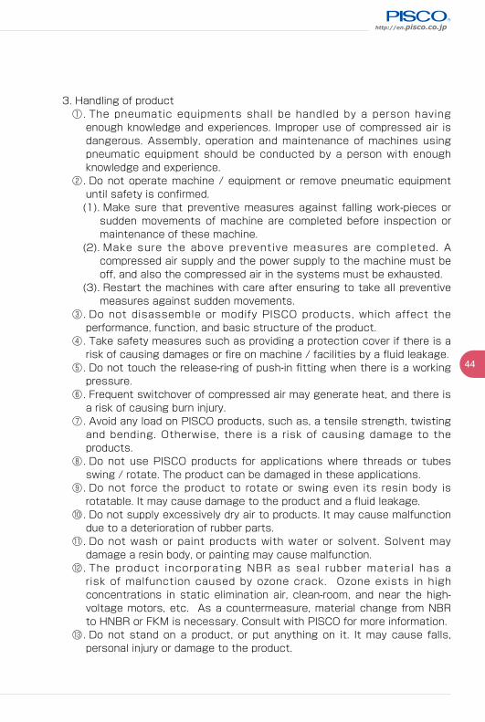
http://en.pisco.co.jp
44
3. Handling of product①. The pneumatic equipments shall be handled by a person having
enough knowledge and experiences. Improper use of compressed air is dangerous. Assembly, operation and maintenance of machines using pneumatic equipment should be conducted by a person with enough knowledge and experience.
②. Do not operate machine / equipment or remove pneumatic equipment until safety is confirmed.(1). Make sure that preventive measures against falling work-pieces or
sudden movements of machine are completed before inspection or maintenance of these machine.
(2). Make sure the above preventive measures are completed. A compressed air supply and the power supply to the machine must be off, and also the compressed air in the systems must be exhausted.
(3). Restart the machines with care after ensuring to take all preventive measures against sudden movements.
③. Do not disassemble or modify PISCO products, which affect the performance, function, and basic structure of the product.
④. Take safety measures such as providing a protection cover if there is a risk of causing damages or fire on machine / facilities by a fluid leakage.
⑤. Do not touch the release-ring of push-in fitting when there is a working pressure.
⑥. Frequent switchover of compressed air may generate heat, and there is a risk of causing burn injury.
⑦. Avoid any load on PISCO products, such as, a tensile strength, twisting and bending. Otherwise, there is a risk of causing damage to the products.
⑧. Do not use PISCO products for applications where threads or tubes swing / rotate. The product can be damaged in these applications.
⑨. Do not force the product to rotate or swing even its resin body is rotatable. It may cause damage to the product and a fluid leakage.
⑩. Do not supply excessively dry air to products. It may cause malfunction due to a deterioration of rubber parts.
⑪. Do not wash or paint products with water or solvent. Solvent may damage a resin body, or painting may cause malfunction.
⑫. The product incorporating NBR as seal rubber material has a risk of malfunction caused by ozone crack. Ozone exists in high concentrations in static elimination air, clean-room, and near the high-voltage motors, etc. As a countermeasure, material change from NBR to HNBR or FKM is necessary. Consult with PISCO for more information.
⑬. Do not stand on a product, or put anything on it. It may cause falls, personal injury or damage to the product.
45
真空発生器・真空ポンプ対応ユニット・真空パッド・真空関連機器SeriesIndexSafety Instructions
Safety Instructions
Warranty
Disclaimer
When the product produces a trouble, which is caused by our responsibility, we will carry out either one of the following measures immediately.①. Free-of-charge replacement of same product②. Free-of-charge repair of the product at our factory
1. PISCO does not take any responsibility for any incidental or indirect loss, such as production line stop, interruption of business, loss of benefits, personal injury, etc., caused by any failure on use or application of PISCO products.
2. When a cause of the trouble/malfunction applies to any of the following items, it is excluded from the coverage of the above warranty.①. A case by a natural disaster, a fire except our responsibility, the act by
the third person/party, the intention or fault of the customer.②. A case when a product is used out of the specific range or the method
listed in the product catalog or the instruction manual.③. A case by the remodeling of the product or by a change of structure,
performance, or specifications which PISCO does not involved in.④. A case by the event that is unpredictable by the evaluations and the
measures at the time on or before the initial delivery.⑤. A case caused by the phenomenon that is able to be evaded if your
machine or equipment has functions or structures that are comprised in a common sense when this product is incorporated in your machine or equipment.
3. T he damages caused by the defect of PISCO products shall be covered but limited to the full amount of the PISCO products paid by the customer. Additionally, the above warranty is limited simply to the product itself. The damage induced by the trouble of the product will not be compensated.
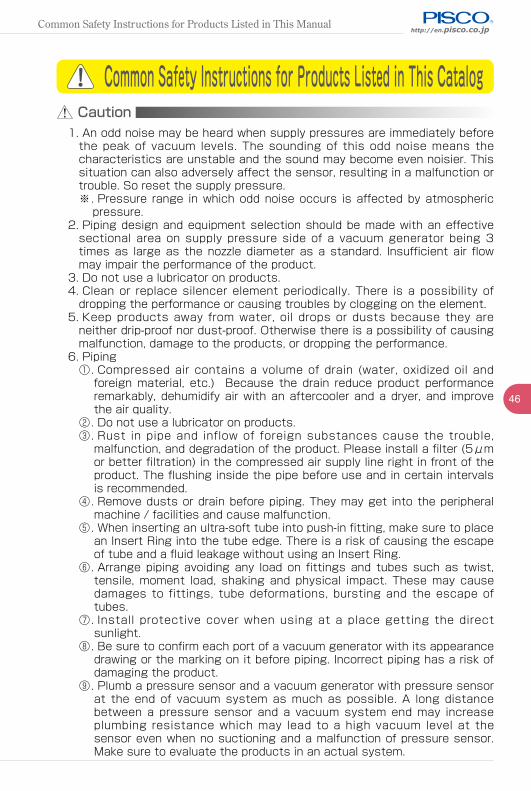
http://en.pisco.co.jp
46
Caution1. An odd noise may be heard when supply pressures are immediately before
the peak of vacuum levels. The sounding of this odd noise means the characteristics are unstable and the sound may become even noisier. This situation can also adversely affect the sensor, resulting in a malfunction or trouble. So reset the supply pressure.※. Pressure range in which odd noise occurs is affected by atmospheric
pressure.2. Piping design and equipment selection should be made with an effective
sectional area on supply pressure side of a vacuum generator being 3 times as large as the nozzle diameter as a standard. Insufficient air flow may impair the performance of the product.
3. Do not use a lubricator on products.4. Clean or replace silencer element periodically. There is a possibility of
dropping the performance or causing troubles by clogging on the element.5. Keep products away from water, oil drops or dusts because they are
neither drip-proof nor dust-proof. Otherwise there is a possibility of causing malfunction, damage to the products, or dropping the performance.
6. Piping①. Compressed air contains a volume of drain (water, oxidized oil and
foreign material, etc.) Because the drain reduce product performance remarkably, dehumidify air with an aftercooler and a dryer, and improve the air quality.
②. Do not use a lubricator on products.③. Rust in pipe and inflow of foreign substances cause the trouble,
malfunction, and degradation of the product. Please install a filter (5μm or better filtration) in the compressed air supply line right in front of the product. The flushing inside the pipe before use and in certain intervals is recommended.
④. Remove dusts or drain before piping. They may get into the peripheral machine / facilities and cause malfunction.
⑤. When inserting an ultra-soft tube into push-in fitting, make sure to place an Insert Ring into the tube edge. There is a risk of causing the escape of tube and a fluid leakage without using an Insert Ring.
⑥. Arrange piping avoiding any load on fittings and tubes such as twist, tensile, moment load, shaking and physical impact. These may cause damages to fittings, tube deformations, bursting and the escape of tubes.
⑦. Install protective cover when using at a place getting the direct sunlight.
⑧. Be sure to confirm each port of a vacuum generator with its appearance drawing or the marking on it before piping. Incorrect piping has a risk of damaging the product.
⑨. Plumb a pressure sensor and a vacuum generator with pressure sensor at the end of vacuum system as much as possible. A long distance between a pressure sensor and a vacuum system end may increase plumbing resistance which may lead to a high vacuum level at the sensor even when no suctioning and a malfunction of pressure sensor. Make sure to evaluate the products in an actual system.
Common Safety Instructions for Products Listed in This Catalog
Common Safety Instructions for Products Listed in This Manual
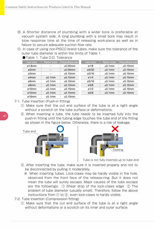
47
真空発生器・真空ポンプ対応ユニット・真空パッド・真空関連機器SeriesIndexCommon Safety Instructions for Products Listed in This Manual
⑩. A Shorter distance of plumbing with a wider bore is preferable at vacuum system side. A long plumbing with a small bore may result in slow response time at the time of releasing work-piece as well as in failure to secure adequate suction flow rate.
⑪. In case of using non-PISCO brand tubes, make sure the tolerance of the outer tube diameter is within the limits of Table 1.●Table 1. Tube O.D. Tolerance
mm size Nylon tube Polyurethane tube inch size Nylon tube Polyurethane tubeø1.8mm ─ ±0.05mm ø1/8 ±0.1mm ±0.15mmø2mm ─ ±0.05mm ø5/32 ±0.1mm ±0.15mmø3mm ─ ±0.15mm ø3/16 ±0.1mm ±0.15mmø4mm ±0.1mm ±0.15mm ø1/4 ±0.1mm ±0.15mmø6mm ±0.1mm ±0.15mm ø5/16 ±0.1mm ±0.15mmø8mm ±0.1mm ±0.15mm ø3/8 ±0.1mm ±0.15mmø10mm ±0.1mm ±0.15mm ø1/2 ±0.1mm ±0.15mmø12mm ±0.1mm ±0.15mm ø5/8 ±0.1mm ±0.15mmø16mm ±0.1mm ±0.15mm
7-1. Tube insertion (Push-in fitting)①. Make sure that the cut end surface of the tube is at a right angle
without a scratch on the tube surface or deformations.②. When inserting a tube, the tube needs to be inserted fully into the
push-in fitting until the tubing edge touches the tube end of the fitting as shown in the figure below. Otherwise, there is a risk of leakage.
7-2. Tube insertion (Compression fitting)①. Make sure that the cut end surface of the tube is at a right angle
without deformations or a scratch on its inner and outer surface.
③. After inserting the tube, make sure it is inserted properly and not to be disconnected by pulling it moderately.※. When inserting tubes, Lock-claws may be hardly visible in the hole,
observed from the front face of the release-ring. But it does not mean the tube will surely escape. Major causes of the tube escape are the followings; ① Shear drop of the lock-claws edge ② The problem of tube diameter (usually small). Therefore, follow the above instructions from ① to ③, even lock-claws is hardly visible.
Tube end
Sealing
Tube is not fully inserted up to tube end.
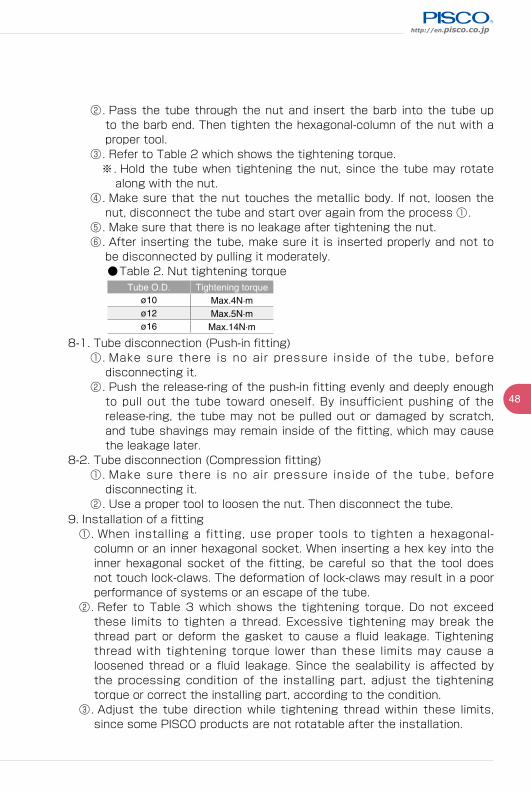
http://en.pisco.co.jp
48
9. Installation of a fitting①. When installing a fitting, use proper tools to tighten a hexagonal-
column or an inner hexagonal socket. When inserting a hex key into the inner hexagonal socket of the fitting, be careful so that the tool does not touch lock-claws. The deformation of lock-claws may result in a poor performance of systems or an escape of the tube.
②. Refer to Table 3 which shows the tightening torque. Do not exceed these limits to tighten a thread. Excessive tightening may break the thread part or deform the gasket to cause a fluid leakage. Tightening thread with tightening torque lower than these limits may cause a loosened thread or a fluid leakage. Since the sealability is affected by the processing condition of the installing part, adjust the tightening torque or correct the installing part, according to the condition.
③. Adjust the tube direction while tightening thread within these limits, since some PISCO products are not rotatable after the installation.
②. Pass the tube through the nut and insert the barb into the tube up to the barb end. Then tighten the hexagonal-column of the nut with a proper tool.
③. Refer to Table 2 which shows the tightening torque.※. Hold the tube when tightening the nut, since the tube may rotate
along with the nut.④. Make sure that the nut touches the metallic body. If not, loosen the
nut, disconnect the tube and start over again from the process ①.⑤. Make sure that there is no leakage after tightening the nut.⑥. After inserting the tube, make sure it is inserted properly and not to
be disconnected by pulling it moderately.●Table 2. Nut tightening torque
Tube O.D. Tightening torqueø10 Max.4N·mø12 Max.5N·mø16 Max.14N·m
8-1. Tube disconnection (Push-in fitting)①. Make sure there is no air pressure inside of the tube, before
disconnecting it.②. Push the release-ring of the push-in fitting evenly and deeply enough
to pull out the tube toward oneself. By insufficient pushing of the release-ring, the tube may not be pulled out or damaged by scratch, and tube shavings may remain inside of the fitting, which may cause the leakage later.
8-2. Tube disconnection (Compression fitting)①. Make sure there is no air pressure inside of the tube, before
disconnecting it.②. Use a proper tool to loosen the nut. Then disconnect the tube.

49
真空発生器・真空ポンプ対応ユニット・真空パッド・真空関連機器SeriesIndexCommon Safety Instructions for Products Listed in This Manual
●Table 3. Tightening torque / Sealock color / Gasket materialsThread type Thread size Tightening torque Sealock color Gasket material
Metric thread
M3×0.5 0.7N·m
n/a
SUS304+NBRSPCC+NBR
M5×0.8 1 ~ 1.5N·mM6×1 2 ~ 2.7N·m
M3×0.5 0.7N·m
POMM5×0.8 1 ~ 1.5N·mM6×0.75 0.8 ~ 1N·mM8×0.75 1 ~ 2N·m
Taper pipe thread
R1/8 4.5 ~ 6.5N·m
White ─R1/4 7 ~ 9N·mR3/8 12.5 ~ 14.5N·mR1/2 20 ~ 22N·m
Unified thread No.10-32UNF 1 ~ 1.5N·m n/a SUS304+NBR, SPCC+NBR
National Pipe Thread Taper
(American standard)
1/16-27NPT 4.5 ~ 6.5N·m
White ─1/8-27NPT 4.5 ~ 6.5N·m1/4-18NPT 7 ~ 9N·m3/8-18NPT 12.5 ~ 14.5N·m1/2-14NPT 20 ~ 22N·m
G threadG1/4 12 ~ 14N·m
n/a Aluminum + PBTG3/8 22 ~ 24N·mG1/2 28 ~ 30N·m
※. These values may differ for some products. Refer to each specification as well.④. When removing a fitting, use proper tools to loosen a hexagonal-column
or an inner hexagonal socket. When inserting a hex key into the inner hexagonal socket of the fitting, be careful so that the tool does not touch lock-claws. The deformation of lock-claws may result in a poor performance of systems or an escape of the tube.
⑤. Remove the sealant stuck on the mating equipment. The remained sealant may get into the peripheral equipment and cause malfunctions.
10. Handling of fitting①. Impact caused by dropping or the like may lead to damage to the
product and a fluid leakage.


![Arm options - ergocentric.com• When rotated 180° the forearm pad moves 2" forward Oval Tube Polyurethane Short Arm Pad Option [OTSH] • Recommended for use with all myCentric series](https://static.fdocuments.net/doc/165x107/5f95c54c180b7c523e4dd312/arm-options-a-when-rotated-180-the-forearm-pad-moves-2-forward-oval.jpg)