Vacuum Packaging Machines - · PDF fileUsers Manual Henkovac 04-serie Page 5 of 32 3.0 Welcome...
32
art.nr. 9606.041EN User Manual Vacuum Packaging Machines T2, T3, T4, T5 M1, M2, M3 M4, M5, M6 M7, M8 D1, D3, D4 D6 http: //www.henkovac.com e-mail: [email protected] tel: +31736271201 SERIAL NUMBER 1ST CHOICE FOR PROFESSIONALS WORLDWIDE
Transcript of Vacuum Packaging Machines - · PDF fileUsers Manual Henkovac 04-serie Page 5 of 32 3.0 Welcome...

art.nr. 9606.041EN
User Manual
Vacuum Packaging Machines
T2, T3, T4, T5 M1, M2, M3 M4, M5, M6 M7, M8 D1, D3, D4 D6
http: //www.henkovac.com
e-mail: [email protected] tel: +31736271201
SERIAL NUMBER
1ST CHOICE FOR PROFESSIONALS WORLDWIDE

Page 2 of 32 Users Manual Henkovac 04-serie
1.0 Safety Regulations and Warnings
General The manufacturer of this equipment accepts no liability whatsoever for damage or injury caused by failing to adhere to the directions
and instructions in this manual, or through carelessness during the installation, use, maintenance and repair of the machine identified
on the front of this document, or any of its accompanying options or components.
The owner of the machine is fully responsible at all times for the adherence to the locally applicable safety regulations and
guidelines. Obey all safety instructions and guidelines as provided in this manual. User Manual
• Every user of the machine should be familiar with the contents of this manual and follow its instructions carefully.
Management must train the appropriate personnel on the basis of this manual and make sure that all directions
and indications are adhered to
• Never change the order of the actions to be taken
• Always keep the manual in the proximity of the machine Pictograms and Instructions on the Machine
• The labels with pictograms, warnings and instructions that are attached to the machine are part of the safety
measures taken. These labels should not be damaged or removed and should remain present and legible
throughout the life of the machine
• Immediately replace or repair any labels that are damaged or have become illegible Intended Use of the Machine
1
The machine is designed for vacuum packaging of food or other products for 8 hours a day, 5 days a week. Any other or extended use is
not in accordance with this purpose and the manufacturer accepts no liability for any resulting damage or injury. Only use this machine
while in perfect technical condition in accordance with the above mentioned purpose. Technical Specifications The specifications outlined in this manual may not be altered.
Modifications Modifications of the machine or its components is not permitted. Safety Measures The machine is equipped with the following standard safety devices:
• Short-circuit and overload safety
• Pump fan guards
All safety devices must be correctly installed and may only be removed to accommodate maintenance and repair activities by trained
and authorized service personnel. The machine may never be operated while safety measures are incomplete, deactivated or absent.
The safety devices may never be by-passed.
1 The “use in accordance with purpose”, as established in EN 292-1, is the use for which the technical product is suitable according to the statement by
the manufacturer, including his directions in the sales brochure. When in doubt, it is the use that manifests itself as the most common, based on the construction, model and function of the product. Use in accordance with the purpose also means adhering to the instructions in the user manual.
2014 HFE Vacuum Systems BV All rights reserved. No part of this document may be reproduced and/or published by means of print, photocopy, microfilm or any other method without the prior written
permission of the manufacturer. This also applies to the accompanying illustrations and/or diagrams and schematics. The information in this document is based on the general data associated with the construction, material characteristics and work methods, known at
the time of publication. Consequently, we reserve the right to make changes to this document without prior notification. This document is applicable to the indicated models of the Henkovac packaging machine in the version supplied. The manufacturer therefore does not
accept any liability for any form of damage or injury resulting from deviating from the specifications of these machines as supplied to you.
All possible care was taken when creating this document, but the manufacturer accepts no liability for mistakes or any consequenses thereof.

Users Manual Henkovac 04-serie Page 3 of 32
2.0 Table of Contents
1.0 Safety Regulations and Warnings 2
2.0 Table of Contents 3 3.0. Welcome 5
3.1 Service from your Dealer 5
3.2 YouTube Henkovac Channel - Instruction and Service Videos 5
4.0 Installation of Machine 6
4.1 Gas Connection for MAP Applications 6
4.2 Compressed Air Connection for Additional Sealing Pressure 6
5.0 Overview of Main Machine Components 7
6.0 Digital Control with LCD Display 8
6.1 One-Program Control System 8
6.2 Operating the Machine with One-Program Control System 9 6.3 Ten-Program Control System 10
6.3.1 Time-Based Operation 10
6.3.1.1 Option Sensor and option Soft-Air retrofit 10
6.3.2 Sensor-Based Operation 10
6.3.2.1 Option Soft-Air retrofit 10
6.4 Operating the Machine with Ten-Program Control System 11
7.0 Programming the Machine 13
7.1 One-Program Control System 13
7.1.1 Programmable Functions 13 7.1.2 Programming 13
7.1.3 Reviewing Function Values for P1 13
7.1.4 Adjusting the Vacuum Time for P1 13
7.1.5 Adjusting the Sealing Time for P1 13
7.1.6 Turning Off Machine 14
7.2 Ten-Program Control System 14
7.2.1 Programmable Functions 14
7.2.2 Reviewing Function Values for P1-P9 14
7.2.3 Programming adjusting Function Values for P1-P9 15
7.2.4 Turning Program Functions ON/OFF 15 7.2.5 Adjusting ON/OFF Functions 15
7.2.6 Turning Off Machine 15
8.0 Symbols in Display 16
9.0 Standard Vacuum Pump Settings: runs continuously or turns off end of cycle 18
9.1 One-Program Control System (stop cycle and aerate, or next step) 18
9.2 Ten-Program Control System (stop cycle and aerate, or next step) 18
10.0 Explanation terminology used 19
10.1 Sensor-Based Control 19
10.2 Time-Based Control 19
10.3 P H2O Program for Liquid Products 19 10.4 Vacuum Plus 19
10.5 MAP Gassing 19
10.6 Sealing 20
10.7 Extra Sealing Pressure 20
10.8 Soft-Air 21
10.9 Multi-Cycle 21
10.10 Cool-Down/Oil Dehumidification 21

Page 4 of 32 Users Manual Henkovac 04-serie
11.0 Maintenance 22
11.1 General 22
11.2 Vacuum Pump 22
11.3 Pump Oil, add or replace 23
11.4.0 Seal Beams and Counter Beams 24
11.4.1 Single-Seal Beam 24
11.4.2 Aluminum/Stainless Steel Seal Beam 25 11.4.3 Aluminum T-Shaped Seal Beam 26
11.4.4 Applying Teflon Tape to Seal Beam 26
11.5 Replacing Silicone Rubber Seal of Counter Beam 27
11.6 Rubber Seal of Vacuum Chamber Cover 27
11.7 Struts, Dampers and Springs 27
11.8 Vacuum Hoses and Tubes 27
12.0 Malfunctions and Notifications 28
12.1 Service and Technical Support 28
12.2 YouTube Henkovac Channel - Instruction and Service Videos 28
12.3 Trouble Shooting Check List 28 13.0 Recommended Spare Parts 29
14.0 Utilities 30
14.1 General data 30
15.0 Commonly-Used Symbols 30
16.0 CE Declaration of Conformity 31

Users Manual Henkovac 04-serie Page 5 of 32
3.0 Welcome Thank you very much for your purchase of a Henkovac vacuum packaging machine. In order to guaran-
tee the reliability, longevity and robustness of your equipment, we only used materials of the highest
quality in the fabrication of your machine. During its design, it was our goal to make it easy to use and simple to maintain.
Based on your purchase of this machine, we assume that you are familiar with the fundamentals of
vacuum packaging. For additional information and guidance about vacuum packaging applications, we
recommend that you contact your dealer.
To find out the location of your nearest dealer, please contact us at:
+31 73 627 12 73 or 77
or via e-mail [email protected].
3.1 Service from your Dealer For technical support, please contact your dealer.
You may also contact us, so that we can assist you in locating your nearest dealer: +31 73 627 12 73 or 77
Please have the following information available:
• Machine type
• Serial number
You can locate the serial number on the front page of this manual. In addition, you can find it on the identification
plate on the right-hand side or back-side of your machine.
3.2 YouTube Henkovac Channel - Instruction and Service Videos
Instructional videos are placed on YouTube for the operation and service of your machine. You may lo-
cate these videos on the YouTube website under “Henkovac Channel”.

Page 6 of 32 Users Manual Henkovac 04-serie
On/Off Button
4.0 Installation of Machine
General • Level the machine on a flat firm surface
• Position the machine in such a manner that the pump is unobstructed and properly ventilated
• Engage the locks on the wheels, if so equipped
• Check the oil level in the pump; add oil if necessary
o Never operate the machine when the oil level is low
Table-Top Model Mobile and Double- Chamber Models
Electrical Connection 3-phase vacuum pump If the machine is incorrectly hooked up to a three-phase electrical connection,
the pump will make excessive noise. If this happens, take the following steps:
• Turn the pump off immediately
• Switch the phase wires
• Make sure that the rotation direction of the pump matches the arrow on the motor housing
Turning on Machine • If so equipped, like some mobile and double-chamber models, turn on the main
power switch on the back of the machine
• Push the on/off button on the control panel of the machine
4.1 Gas Connection for MAP Applications (Modified Atmospheric Packaging) • Connect the gas supply line to the inlet on the back of the machine
• Maximum pressure: 1 bar
• Anchor the gas cylinders securely to prevent them from falling over
• Make sure that the work area is well-ventilated
• To assure that you use the appropriate gas for your application, consult
your dealer or gas supplier
• Assure a good connection and use high-quality materials
4.2 Compressed Air Connection for Additional Sealing Pressure • Additional sealing pressure is usually recommended for MAP applications only
• The M4-M8 and the D1-D6 models with the option Gas/MAP are standard equipped
with a compressed air inlet
• Extra sealing pressure is not necessary and not available for the Table-Top, M1, M2, M3
• Consult your dealer for installation details
• Maximum pressure: 1 bar
• Assure a good connection and use high-quality mater
Oil sight glass Wheel locks Oil sight glass

Users Manual Henkovac 04-serie Page 7 of 32
5.0 Overview of Main Machine Components
Position Description Page Position Description Page
A Control panel 8-18 H Silicone sealing gasket 27
B
Seal beam (located in the
cover on the double-
chamber machines)
24-26 I
Identification plate
5, 28
C Counter beam 27 J Main switch
D MAP gassing pipes 20 K MAP gas connection 20
E Fitting plates (optional)
L Compressed air connection (ex-
tra sealing pressure option) 21
F
Exhaust (located in the
cover on double-chamber
and some mobile models)
M Wheel with lock
G Cover lock (not for dou-
ble-chamber machines)
D
C
L
H
G
B
I
F
E
F
A
A
H
A
G
B
E
I
I
C
C
M
On the back side of the machine:
J Main switch
K MAP gas connection
L Compressed air connection E
K
M
J

Page 8 of 32 Users Manual Henkovac 04-serie
6.0 Digital Control with LCD Display Some Henkovac vacuum machines have a control system with just one Program (P1). Other machines
have an optional expanded control system, which can accommodate up to 9 custom programs (P1-9).
6.1 One-Program Control System Henkovac machines with the One-Program control system
can be programmed for the following 2 functions:
1. Vacuum time (seconds)
2. Sealing time (seconds)
• The values for vacuum and sealing times are selected by the user and saved in program P1
• During operation, the LCD display will show symbols to indicate the active function and the pro-
gress of the packing cycle
• The actual vacuum pressure is indicated by the analog vacuum gauge
Plug & Play
• When turning on the machine for the first time:
o running time of the vacuum pump is pre-set at 30-40 seconds and the sealing time at
2 seconds. Vacuum is indicated on the analog vacuum gauge.
• When turning on the machine after that, program P1 will contain the most-recently used settings
• The vacuum and sealing times are easily adjusted to match the needs for the application

Users Manual Henkovac 04-serie Page 9 of 32
6.2 Operating the Machine with One-Program Control System
On: Turns the machine on
o The machine will start up in the most-recently used program o The pump of a machine with a transparent cover will start when the cover is closed
Off: Turns the machine off o When pressing the button once, the symbol will start blinking and the pump will
stop after about 4 seconds
o When pressing the button a second time, the pump will stop immediately
o Closing the cover will initiate the cool-down phase; the machine will complete a num-
ber of vacuum cycles before turning off automatically
Stop-function o Stops the machine at any point in the packing cycle and aerates the chamber
Reset-function o While programming, resets the program value to its original setting
Press the menu button to return to the Home menu
Packing of
sauce/soup
Stops the current function and initiates the next step in the cycle o By pressing the of the sealing button , the vacuum function stops and the pro-
gram jumps to the sealing function
o While packing sauce or soup, the package may be sealed as soon as product boiling is
detected
Entering the desired vacuum time o By pressing the + or – of the vacuum button , the vacuum time can be increased or
decreased
The selected value is confirmed and saved by pressing the menu button o Press the button to reset the original value
Entering the desired sealing time o By pressing the + or – of the sealing button , the sealing time can be increased or de-
creased
The selected value is confirmed and saved by pushing the menu button o Press the button to reset the original value
Menu Button o Confirms and saves the entered values for vacuum and sealing times
o Returns to the Home menu
When turning off the machine with the button, the symbol will start blinking o The pump will stop after about 4 seconds
o Press the button a second time and the
pump will stop immediately
o Close the lid; the machine initiates the cool-down
phase and perform a number of vacuum cycles before turning off automatically
o These additional cycles allow any moisture in the oil of the pump to evaporate. This in-
creases the longevity of the machine and minimizes the need for oil changes
and pump maintenance

Page 10 of 32 Users Manual Henkovac 04-serie
Service Symbol o After a number of operating hours or packing cycles, the
service symbol will briefly appear on the display
when the machine is turned on. In addition, the display
indicates how many hours or cycles remain before an oil change is required
o Except for regularly changing the oil in the pump (important!), the machine requires lit-
tle other routine maintenance
o To reset the service interval counters after the oil change: Start machine and while
the display shows the hours or cycles, press and hold the button
6.3 Ten-Program Control System In addition to vacuum and sealing times, Henkovac machines with a Ten-Program control system may
be programmed for several additional functions. Each of the 9 customizable programs is either
1. time-controlled
2. sensor-controlled
6.3.1 Time-Based Operation (vacuum gauge: mbar)
• The values for vacuum and sealing time, as well as the values
for several optional functions, are selected by the customer
and saved in any of 9 customizable programs P1-9
• When operating a packaging machine with a time-based program, the actual vacuum pressure is indicated by the
analog vacuum gauge. The number of seconds of vacuum time
remaining is shown on the LCD display
Plug & Play
• When turning on a time-based machine for the first time, it will start up in the PA program
. This is a pre-set factory program with 30-40 seconds vacuum time and 2 seconds of
sealing time
• When turning on the machine after that, it will start up in the most-recently used program
6.3.1.1 Optional installation of a Sensor or Soft-Air • A machine with a time-based control program can be upgraded to sensor-based operation at a lat-
er date by installing the optional sensor kit
• The Soft-Air feature can also be installed at a later date by ordering the optional soft-air kit
6.3.2 Sensor-Based Operation (digital display: mbar) • When operating a packaging machine with a sensor-based
program, the actual vacuum pressure is digitally shown on
the LCD display in mbar (standard setting) or in % vacuum
Plug & Play
• When turning on a sensor-based machine for the first time, it will start up in the PA program . This is a pre-set factory program with 5 mbar of vacuum and 2 seconds of
sealing time
• When turning on the machine after that, it will start up in the most-recently used program
6.3.2.1 Optional installation of Soft-Air • The Soft-Air feature can also be installed at a later date by ordering the optional soft-air kit
Users Manual Henkovac 04-serie Page 11 of 32
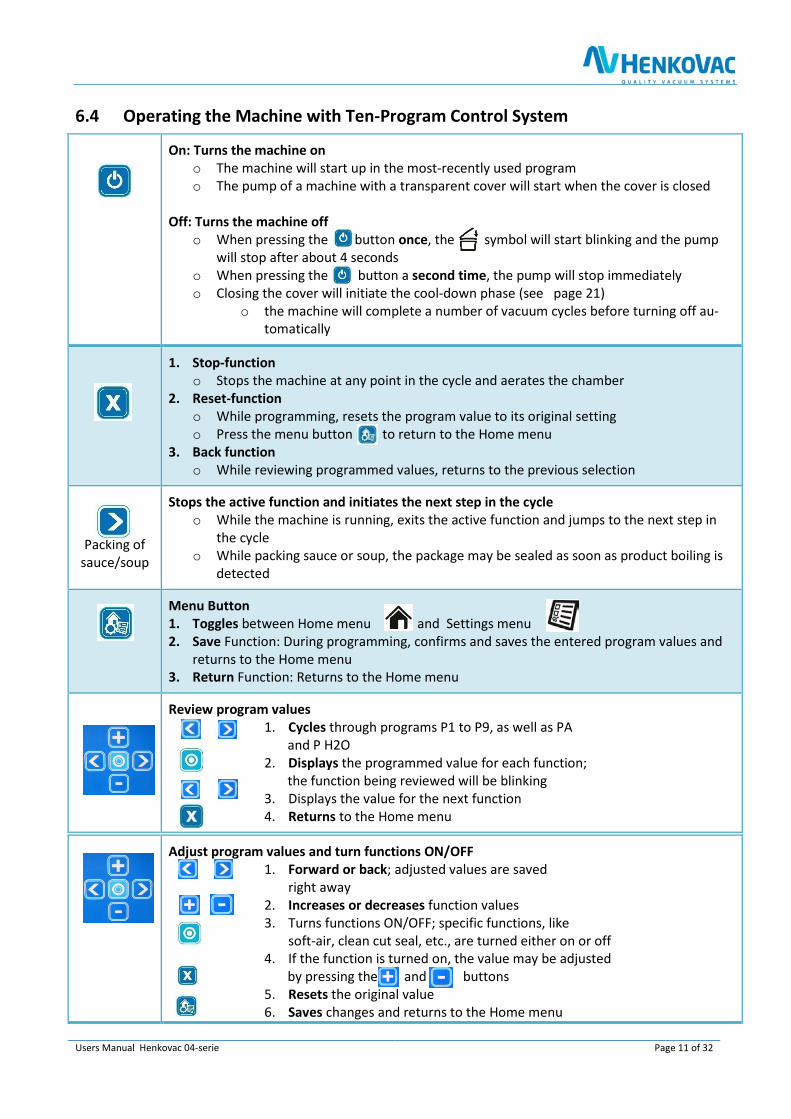
6.4 Operating the Machine with Ten-Program Control System
On: Turns the machine on
o The machine will start up in the most-recently used program
o The pump of a machine with a transparent cover will start when the cover is closed
Off: Turns the machine off
o When pressing the button once, the symbol will start blinking and the pump
will stop after about 4 seconds
o When pressing the button a second time, the pump will stop immediately
o Closing the cover will initiate the cool-down phase (see page 21)
o the machine will complete a number of vacuum cycles before turning off au-tomatically
1. Stop-function o Stops the machine at any point in the cycle and aerates the chamber
2. Reset-function o While programming, resets the program value to its original setting
o Press the menu button to return to the Home menu
3. Back function o While reviewing programmed values, returns to the previous selection
Packing of
sauce/soup
Stops the active function and initiates the next step in the cycle o While the machine is running, exits the active function and jumps to the next step in
the cycle
o While packing sauce or soup, the package may be sealed as soon as product boiling is
detected
Menu Button 1. Toggles between Home menu and Settings menu 2. Save Function: During programming, confirms and saves the entered program values and
returns to the Home menu 3. Return Function: Returns to the Home menu
Review program values 1. Cycles through programs P1 to P9, as well as PA
and P H2O
2. Displays the programmed value for each function;
the function being reviewed will be blinking
3. Displays the value for the next function
4. Returns to the Home menu
Adjust program values and turn functions ON/OFF 1. Forward or back; adjusted values are saved
right away
2. Increases or decreases function values
3. Turns functions ON/OFF; specific functions, like
soft-air, clean cut seal, etc., are turned either on or off 4. If the function is turned on, the value may be adjusted
by pressing the and buttons
5. Resets the original value
6. Saves changes and returns to the Home menu

Page 12 of 32 Users Manual Henkovac 04-serie
Multi-Functional button: Performs various functions, depending on the active menu
Home menu:
o No effect while in the PA program
o For programs P1-9, displays the entered values
Settings menu: o For specific functions, like soft-air, clean cut seal etc., the
button is used to turn the function ON/OFF
P1 – P9
PA
P H2O
Programs 1 through 9
o Each program may be customized by turning certain functions on or off and by adjust-
ing the function values PA - Automatic
o Program with factory settings for vacuum and sealing functions, which is activated
when turning on the machine for the first time
P H2O – Program
o To be used when packing liquids or semi-liquids, like sauces and soups (see page 19)
o Program jumps to the sealing function as soon as product boiling is detected; this pre-
vents product loss through spillage and evaporation
When turning off the machine with the button, the symbol will start blinking on the LCD display
o The pump will stop after about 4 seconds
o Press the button for a second time and the pump will stop immediately
o Close the lid; the machine will initiate the
cool-down phase and perform a number of
vacuum cycles before turning off automatically
o These additional cycles allow any moisture in the oil of the pump to evaporate. This in-
creases the longevity of the machine and minimizes the need for oil changes and pump
maintenance
Service Symbol o After reaching a certain number of operating hours
or packing cycles, the service symbol will briefly
appear on the display when turning on the machine.
In addition, the display indicates how many hours
or cycles remain before an oil change is required.
o Except for regularly changing the oil in the pump, the machine requires little other routine maintenance
o After reaching the service limit, the display will indicate the negative number of ex-
ceeded operating hours or cycles
o To reset the service interval counters after the oil change: Start machine and while
the display shows the hours or cycles, press and hold the button

Users Manual Henkovac 04-serie Page 13 of 32
7.0 Programming the Machine
7.1 One-Program Control System • The One-Program control system is standard on the T2, T3, T4, T5, M1, M3 (with 21m3 pump)
• The One-Program control system is time-based
• The Ten-Program control system (time or sensor) is optional for these models, except for T2
The One-Program control system provides only one program (P1)
• There is no memory to store additional values
• The machine starts with the values that were most-recently used
• The pump starts upon closing of the cover and stops when it is reopened
7.1.1 Programmable Functions The following function values may be customized for P1:
• Vacuum time: in seconds
• Sealing time: in seconds
7.1.2 Programming 1. Turn the machine on by pressing the on/off button
a. The factory setting for the vacuum time is 30-40 seconds
b. The factory settings for the seal time is 2 seconds
7.1.3 Reviewing Vacuum Time and Sealing Time
1. Press the button to display the programmed vacuum time
the vacuum time is pre-set at the factory
2. Press the button to display the programmed sealing time
the sealing time is pre-set at the factory at 2 seconds
7.1.4 Adjusting Vacuum Time for P1 1. Press twice on the or button
o After pressing once, the programmed value
is displayed
o After pressing twice, the symbol will start blinking
and the value may be adjusted
2. Save the new value by pressing the menu button 3. To retain the original value, press the button
4. Exit the program by pressing the menu button
7.1.5 Adjusting Sealing Time for P1
1. Press twice on the or button o After pressing once, the programmed value
is displayed
o After pressing twice, the symbol will start blinking
and the value may be adjusted
2. Save the new value by pressing the menu button
3. To retain the original value, press the button
4. Exit the program by pressing the menu button

Page 14 of 32 Users Manual Henkovac 04-serie
7.1.6 Turning Off Machine 1. Turn the machine off by pressing the button
2. The symbol on the display will start blinking 3. Push the button a second time and the pump will stop immediately 4. If no action is taken the pump turns off after 4 seconds
5. Close the cover and the machine will initiate the cool-down phase and
perform a number of vacuum cycles while the cover stays closed and
the machine will turn off automatically after about 15 minutes
• These cycles are necessary to cool down the machine and to allow
any moisture in the oil of the pump to evaporate
7.2 Ten-Program Control System • The Ten-Program control system is standard time-based on the
M2, M4-M8, D1-D6
• sensor-based operation is an option, which can be installed at a later date
• The Ten-Program control system provides:
1. 9 customizable programs (P1-P9)
2. Program PA; this is an - Automatic Program –
Pre-set at the factory at a vacuum time of 30-40 seconds
(or 5 mbar for a sensor-based program) and a sealing time
of 2 seconds
3. Program P H2O for liquid products (see page 19)
• When turning on the machine, the pump will start. After about 15 minutes of inactivity, the pump will stop automatically
7.2.1 Programmable Functions The following functions may be customized for each program P1-P9:
Vacuum time: in seconds or mbar (only with sensor)
Sealing time: in seconds
Vacuum Plus: on/off, in seconds
Gassing: on/off, in seconds or mbar (only with sensor) Clean Cut Controlled (CCC) Seal: on/off, in seconds
Soft-Air: on/off, in seconds or mbar (only with sensor)
Multi-cycle: on/off, in number of cycles
7.2.2 Reviewing Function Values for P1-P9 1. Turn the machine on by pushing the button
2. The most-recently used program will be indicated, for instance P3
3. All selected functions for this program are indicated at the bottom of the display
4. To review the values for these functions, push the button; use the button to display each function value
5. The values cannot be changed; this can only be done in the Settings menu
6. Push the button to return to the Home menu

Users Manual Henkovac 04-serie Page 15 of 32
7.2.3 Programming and Adjusting Values for P1-P9 1. Select the program to be set up or adjusted, for instance P2
2. Push the menu button to access the Settings menu
3. All functions for the selected program are indicated at the bottom of the display
4. Push the button to select the blinking function to be adjusted
5. Adjust the value of the selected function with the button
6. Press the button to reset all functions to their original values
7. Select the next function with the button
8. Press the menu button to save the entered values and to return to the Home menu
7.2.4 Turning Program Functions ON/OFF
The following functions can be turned ON/OFF for each program P1-P9:
Vacuum Plus: on/off, in seconds Gassing: on/off, in seconds or in mbar (only with sensor)
Clean Cut Controlled (CCC) Seal: on/off, in seconds
Soft-Air: on/off, in seconds or in mbar (only with sensor) Multi-cycle: on/off, in number of cycles
7.2.5 Adjusting ON/OFF Function Values 1. Press the menu button to select the Settings menu
2. Use the button to select the blinking function to be adjusted
3. For instance, the gassing function is turned off. Press the button
to turn this function on
4. Press the button to select the desired value, for instance 180 mbar
5. Press the button to reset all functions to their original values
6. Select the next function with the button
7. Push the menu button to store all selected values and to
return to the Home menu
7.2.6 Turning Off Machine • Follow the same procedure as for the One-Program control system, as explained on page 14

Page 16 of 32 Users Manual Henkovac 04-serie
8.0 Symbols in the Display • Not all symbols are visible at all times
• By default, the display will show the Home menu, indicating the program number (P1 through P9) and digital readout for actual vacuum time or pressure (mbar)
• The symbols for all selected program functions will show at the bottom of the display. The symbol
for the active function will be blinking
• The remaining two symbols on the right-hand side will be visible when applicable
Home Menu o Standard default display, showing the progress of the packing cycle o Programmed function values can be reviewed by pushing the button
Service Menu o Factory settings; dealer access only
Settings Menu o To enter and adjust the programmable function values
o P -Active-Program Display
o Up to 9 customizable programs may be entered and displayed
o The PA and P H2O programs are pre-set at the factory
o PA = Program Automatic: This Plug & Play program has factory settings for vacu-
um and sealing functions. The pre set values are most commonly used o P H2O program: This program is specially designed for liquid products to prevent
boiling and excessive evaporation
o P1-P9 can be individually programmed depending on the options available
o Standard Plug & Play program runs when turning on the machine for the first time o Vacuum time or pressure, and sealing time are factory pre-set and cannot be changed
Display of the value of the active function o Displays vacuum pressure in mbar (standard) or in % (for sensor-based applications) o Displays remaining vacuum time in seconds (for time-based applications)
o sealing time, vacuum-plus time, soft-air time or pressure, MAP time or pressure, mul-
ti-cycle count, etc.
o when oil change indicator is shorty shown at the start of the machine: displays re-
maining production hours or cycles before an oil change is required
o Programmable in the Settings menu
Home Menu:
Default display
Settings Menu:
To adjust values for
program functions Symbols to show the active function
and the packing cycle progress
Indicator for actual vacuum pres-
sure or time, sealing time, etc. In the presence of the service indi-cator, the remaining production
hours or cycles will be briefly incat-ed at start up
This symbol will blink when turning
off the machine. When closing the cover, the machine will perform a number of vacuum cycles before
turning off automatically. This al-lows any moisture in the oil to evaporate
• Programs P1 thru P9
• PA Automatic (sensor)
• P H2O liquid (sensor)

Users Manual Henkovac 04-serie Page 17 of 32
SYMBOLS INDICATING PROGRESS OF THE PACKING CYCLE
o
Cycle Progress Indicator o This symbol rotates during the packing cycle
Vacuum Process o In the presence of a sensor, the vacuum measurement is digitally displayed.
o When operating a time-based program, the vacuum measurement is indicated by the analog vacuum gauge
Vacuum Plus (page 19: 10.4) o With a sensor controlled machine, a number of seconds may be added to the vacuum
process after the programmed pressure value has been reached
MAP Gassing (optional; for sensor-based operation only) (page 20: 10.5) o During the MAP (Modified Atmospheric Packaging) gassing process, the package is
vacuated down to a programmed value, for instance 600 mbar; the vacuum meas-
urement is shown in the display o The gassing time count-down is displayed in seconds, or the increasing pressure is
displayed in mbar or %
Sealing (page 20: 10.6) o The package is heat-sealed for a programmable number of seconds (single-double-
clean cut)
Clean Cut Controlled Seal (optional) (page 20: 10.6) o Special sealing method, by which a second heating wire scores the package, making it
easy to remove the excess packaging material o The additional wire is time-controlled independently; the scoring time is displayed
Soft-Air (optional) (page 21: 10.8)
o The vacuum chamber is aerated more slowly. This allows the packaging material to
gradually conform to irregularly-shaped products and prevents sharp objects from
puncturing the bag
o The aeration time count-down is displayed in seconds, or the gradually increasing
pressure is displayed in mbar or %
Multi-Cycle (for MAP applications only) (page 21: 10.9)
o After the package is vacuated down to the programmed value, it is gassed and re-
vacuated a number of times. The objective of this procedure is to minimize the amount of oxygen remaining in the package
o The number of cycles is counted down in the display

Page 18 of 32 Users Manual Henkovac 04-serie
Cool-Down/Oil Dehumidification Phase (page 21: 10.10) o When turning off the machine with the button, the
symbol will start blinking in the LCD display and the pump will
stop after about 4 seconds
o Press the button a second time and the pump will stop immediately
o Close the lid and the machine will initiate the cool-down phase by performing a number
of vacuum cycles before turning off automatically
o These additional cycles allow any moisture in the oil of the pump to evaporate. This in-
creases the longevity of the machine and minimizes the need for oil changes and maintenance
Service Indicator: Oil Change o After a number of operating hours or packing cycles, the
service symbol will briefly appear on the display when
turning on the machine. In addition, the display will
indicate how many hours or cycles remain before an oil change
is required o After reaching zero, the display will indicate the negative number of exceeded operating
cycles or hours
o To reset the service interval counters after the oil change: Start machine and while
the display shows the hours or cycles, press and hold the button
9.0 Standard Vacuum Pump Settings:
1. Pump stops after vacuum cycle 2. Pump runs continuously; stops after 15 minutes
• The pump of mobile packaging machines M1, M2 and M4, M5, M6, M7, M8, as well as the pump of double-chamber units D1, D3, D4 en D6, runs continuously. After completion of a packing cy-
cle, the pump will stop after 15 minutes of inactivity.
• The pump of table units T2, T3, T4 and T5 starts when the cover is closed; the pump stops when
the cover is opened again.
• The 21m3 pump of the M3 continues to run, while the 40m3 pump stops between packing cycles
• These settings may be adjusted by the dealer in the Service menu
9.1 One-Program Control System Stop the cycle and aerate:
• By pressing the button during the packing cycle, the active function is stopped, the cham-ber is aerated and the cover opens. Subsequent functions in the cycle are cancelled
Stop the cycle and start sealing
• By pressing the of the sealing button , the vacuum function is interrupted and the pro-
gram jumps to the sealing function
9.2 Ten-Program Control System Stop the cycle and aerate:
• By pressing the button during the packing cycle, the active function stops, the chamber is aerated, and the cover opens. Subsequent functions in the cycle are cancelled
Stop the cycle and start sealing
• By pressing the button, the packing cycle is interrupted and the program jumps to the next
function in the process

Users Manual Henkovac 04-serie Page 19 of 32
10.0 Further Explanation of Packaging Concepts
10.1 Sensor-Based Control The actual air pressure in the chamber is measured by a sensor. The result of this measurement is digi-
tally indicated on the LCD display.
Normal air pressure is about 1000 mbar. The vacuum pump of the machine reduces this to about 2-5
mbar. Depending on the program, the pressure by which certain functions need to take place can be
programmed. Examples are MAP gassing and Soft-Air.
The air pressure in time-controlled machines is indicated by the analog vacuum gauge.
10.2 Time-Based Control • The standard control of a One-Program machine, as well as a Ten-Program machine, is time-based
• The Ten-Program time based machine can be converted into sensor-based operation by
ordering the optional sensor kit
A time-controlled machine is programmed with a time value in seconds, according
to which a desired vacuum is reached. The vacuum measurement is indicated by the
analog vacuum gauge. The reading of the analog vacuum gauge is less accurate than
the digital reading of a sensor-controlled machine.
• The Ten-Program machine can be retro-fitted with a sensor kit at a later date. The control system
recognizes the sensor and will automatically switch over to sensor-based operation
• In case the sensor should fail, the machine will automatically switch over to time-based operation
10.3 P H2O Program for Liquid Products • Only for Ten-Program machines with sensor-based control
• Specially designed for the packaging of cooled liquid products like sauces and soups at tempera-
tures < 150C (600F)
Under normal air pressure (1000 mbar), water boils at 100o C. At that point, water transfers rapidly
from a liquid phase to a gas phase. At lower air pressure, boiling starts at a lower temperature as well as rapid evaporation. To avoid product loss through evaporation and spillage, the P H2O program de-
tects the point of boiling and initiatese sealing function in the cycle. Since air is replaced by water va-
por at this point, the oxygen content in the package will be very low.
10.4 Vacuum Plus (seconds) • Only for Ten-Program machines with sensor-based control
• Can be turned on or off in the Settings menu
After reaching a programmed vacuum pressure, the sealing function may be delayed by adding a pro-grammable number of seconds to the vacuum process. This enables any air to escape from porous
products.
10.5 MAP Gassing (option) • Only for Ten-Program machines with sensor-based control
• Can be turned on or off in the Settings menu
After reaching a programmed vacuum pressure, the package is filled with an inert gas, such as CO2, nitrogen, oxygen, or a mixture thereof. This feature is
either time or pressure-controlled.

Page 20 of 32 Users Manual Henkovac 04-serie
10.6 Sealing The synthetic packaging material is melted shut by a heated sealing wire.
single seal double seal clean cut & two-sided seal
clean cut controlled
• Single Seal Only for T2. The package is sealed with a single sealing wire
• Double Seal All other machines are equipped with a double sealing wire
• Clean Cut Seal (CC Seal)
One of the two heated wires is used to score the package. This makes it easy to remove the
excess packaging material. The package has one seal and a nicely trimmed edge.
• Clean Cut Controlled Seal (CCC Seal) o Only for Ten-Program machines with sensor-based control
o Can be turned on or off in the Settings menu
Identical to the Clean Cut seal, with the only difference that the heating time for the scoring wire
can be programmed independently. This improves control over the scoring process. Typically used
for shrink bags.
• Two-Sided Seal o Only for Ten-Program machines with sensor-based control
o Can be turned on or off in the Settings menu
The counter beam contains a sealing wire as well. Used for thick material or metallic packaging materials, requiring additional heat to seal the bags.
10.7 Extra Sealing Pressure During the sealing process, the package is held in place between the seal beam and
the counter beam. To assure a proper package seal, additional air pressure to the sealing
beam may be beneficial (maximum of 1 bar), for instance during MAP gassing
above 500 mbar.
• The M4-M8 and the D1-D6 models with the option Gas/MAP are standard equipped
with a compressed air inlet. Otherwise it can be easily retrofitted.
• Extra sealing pressure is not necessary and not available for the Table-Top, M1, M2, M3

Users Manual Henkovac 04-serie Page 21 of 32
10.8 Soft-Air (option) • Only for Ten-Program machines with sensor-based control
• Can be turned on or off in the Settings menu
After the vacuum and sealing process, the chamber is aerated and brought back to ambient air
pressure. Since this happens quickly, the packaging material conforms to the product quickly as well. If the product has sharp edges, the packaging material may be punctured during this process.
With the Soft-Air feature, air is introduced into the vacuum chamber in a slower and controlled man-
ner. As a result, the packaging material gradually conforms to the product, thus avoiding damage. This
feature is either time or pressure-controlled. Machines with a Ten-Program control system can be ret-
ro-fitted with this feature.
10.9 Multi-Cycle • Only for Ten-Program machines with sensor-based control
• Can be turned on or off in the Settings menu
• Only in combination with MAP gassing
This option minimizes the amount of oxygen in the product. The machine vacuates and gases the package several times in a row, thus flushing air and oxygen from the chamber and the package.
This feature is used for delicate products that do not permit vacuation down to 5 mbar, while at the
same time requiring a low oxygen content.
10.10 Cool-Down/Oil Dehumidification of the vacuum pump
During the vacuum process, moisture is removed from the product through evaporation. This moisture
can be absorbed by the oil of the vacuum pump. Too much moisture in the oil will reduce the effec-
tiveness of the pump. In addition, it will reduce the lubrication properties of the oil, affecting the lon-
gevity of the pump. Heat and ventilation will dissipate this moisture, for which reason it is important
to let the pump run for some time at the end of production.
• Turn the machine off with the button and close the cover
when the symbol starts blinking. The pump will continue to run
for some time, before turning off automatically. This allows
any moisture in the oil of the pump to evaporate

Page 22 of 32 Users Manual Henkovac 04-serie
11.0 Maintenance
11.1 General Regular maintenance prevents equipment malfunctions and prolongs the life of the machine.
In addition, it optimizes sanitary conditions.
• Always have a certified Henkovac dealer carry out repair and maintenance activities
Warning • During maintenance activities, always turn the machine off at the main switch and/or unplug it
from the electrical outlet
Attention Observe the recommended service intervals. Overdue maintenance may lead to costly repairs and overhauls, and may void the equipment warranty
• After reaching a programmed number of operating hours or packing
cycles, the service symbol will briefly appear on the display
when the machine is started up. In addition, the display will indicate
how many hours or cycles remain before an oil change is required
• After passing the service limit, the display will indicate the negative
number of excess operating hours or cycles
11.2 Vacuum Pump To protect the vacuum pump, proper maintenance is important. Carry out the following tasks carefully:
• Check the vents and clean as necessary before turning on the machine to assure proper cooling of the
pump
• When the air filter is saturated with oil, an oil mist may be expelled; replacement of the filter is
required
• Use the cool-down/dehumidification feature. When turning off the machine and closing the cover , the pump continues to run for some time. Any moisture in the oil of the pump will
evaporate during this phase. This increases the longevity of the machine and minimizes the need
for oil changes and pump maintenance
• Check the oil level regularly and add as needed
• Change the oil when the service symbol appears on the display
Note To reset the service interval counters after the oil change: Start machine and while the display
shows the hours or cycles, press and hold the button

Users Manual Henkovac 04-serie Page 23 of 32
11.3 Adding and Changing the Pump Oil
Warning The operating temperature of the pump is 70° C / 158° F or higher. Wear gloves when
servicing the pump or let it cool off sufficiently to prevent injuries.
Table Models Mobile or Double-Chamber Models
A
B/C A
B
C
Recommended Oil Types
Recommended Oil Types DIN 51506
Pumps
HLPT 22 4m3
VG032 8m3 - 16m3 - 21m3 1-phase pump
VG068 40m3 - 63m3 1-phase pump
VG 100 40m3 - 300m3 3-phase pump
Adding Oil
1. Remove the oil filler cap
2. Add oil up to the maximum-level mark; use oil according to DIN 51506, lubrication oil group VC;
See ‘Technical Specifications’ for additional information. When in doubt, consult your dealer
3. Replace the oil filler cap
4. After several packing cycles, check the oil level and add as needed
Changing Oil 1. Remove the oil drain plug and drain the oil
2. Replace the drain plug
3. Remove the oil filler cap
4. Add the correct oil up to the maximum-level mark
5. Replace the oil filler cap
6. To reset the service interval counters after the oil change: Start machine and while the dis-play shows the hours or cycles, press and hold the button
Note Collect the oil to have it processed and recycled according to the locally applicable regulations
A Oil filler cap
B Oil sight glass
C Oil drain plug

Page 24 of 32 Users Manual Henkovac 04-serie
11.4.0 Seal Beams and Counter Beams To achieve a quality seal, it is necessary that the seal beam and counter beam are in good condition.
1. Clean the seal and counter beams daily with a dry cloth
2. Replace the Teflon tape on the seal beam if damaged and replace the sealing wire if kinked 3. Replace the silicone rubber seal if it is burned in
Depending on the type of machine, there are three seal beam versions:
1. Single-seal beam (T2)
2. Stainless steel seal beam
3. Aluminum seal beam
11.4.1 Single-Seal Beam
Remove the sealing wire and Teflon tape as follows: 1. Grab the seal beam in the middle and pull it straight up and out of the machine
2. The beam is held in place by 2 pins; some force may be necessary to loosen the beam
3. Remove the brown Teflon tape (A) that is applied to the seal beam
4. Remove the two screws (F) on the underside of the seal beam; this releases the sealing wire (B) 5. Clean the seal beam thoroughly and remove any glue residue of the Teflon tape
Notes
• Check the condition of the tensioning springs (D) at both ends of the seal beam; replace if necessary
• These springs maintain tension on the sealing wire
• Using the seal beam without the springs may cause
sealing wires to break
Install the sealing wire and Teflon tape as follows: 1. Position the sealing wire across the beam and fasten it on one side with a small bolt
2. Apply tension on the wire by pulling it with a pair of pliers
3. Fasten the wire on the opposite end of the beam with the second bolt and cut the wire to
length; the ends of the sealing wire must be long enough to make electrical contact with the pins
in the vacuum chamber 4. Apply the Teflon tape smooth and tight over the seal beam; make sure that the beam is clean and
free of grease
5. Re-install the beam in the vacuum chamber; check to make sure that the ends of the sealing wire
make contact with the steel pins

Users Manual Henkovac 04-serie Page 25 of 32
11.4.2 Aluminum/Stainless Steel Seal Beam
Remove the sealing and cutting wires as follows: 1. Remove the old wires by pulling them loose from the seal beam contacts
2. Loosen the clamp screws and remove the seal beam from the U-profile
3. Remove the Teflon tape from the seal beam
4. Remove the mounting plates (C) on both ends of the seal beam by loosening the screws; this re-
leases the sealing wires (B) and/or sealing and cutting wires
5. Clean the seal beam thoroughly
Notes
• After removal of the wires, check the strips of
fiber glass(A) for damage; replace if necessary
• Check the condition of the tensioning springs
(D) at both ends of the seal beam; replace if
necessary.
• Using the seal beam without the springs may cause the sealing wires to break
• Check contact plate (E) for damage; replace if
necessary
Install the sealing and cutting wires as follows: 1. If necessary, install new strips of fiber glass on
the seal beam
2. Insert the new wires (B) behind one of the
mounting plates (C) and tighten the screws (D); make sure that the end of the wires line up
with the bottom edge of the mounting plate
3. Position the wires across the seal beam and
loosely install the second mounting plate
4. Carefully clamp the seal beam upside down in a
bench vice
5. Pull the wires as tightly as possible with a pair
of pliers (A) and secure the second mounting plate (D)
by tightening the screws
Note 1. The wires can be further tightened by slightly loosening the
screws of one of the mounting plates
2. Pull the wires one-by-one tighter with a pair of pliers;
3. Re-tighten the screws after the correct tension has been achieved 4. Cut the end of the wires flush with the bottom edge of the
mounting plate
5. Apply the Teflon tape smooth and tight over the seal beam without creases
Make sure that the beam is clean and free of grease
6. Re-install the seal beam in the vacuum chamber and re-connect the wires
C B A
DC
E
A B C D

Page 26 of 32 Users Manual Henkovac 04-serie
11.4.3 Aluminum T-Shaped Seal Beam
Remove the sealing wires as follows: 1. Remove the seal beam from the machine
2. Remove the Teflon tape
3. Loosen the screws (D) on both sides of the beam; this will release the sealing wires (B)
4. Clean the seal beam thoroughly
Install the sealing wires as follows: 1. Apply new fiber glass (A) to the beam if necessary
2. Place new wires (B) on the beam and fasten them on one
side with mounting plates (C); tighten the screws (D)
3. Position the wires across the beam
4. Fasten mounting plates (C); tighten screws (D)
5. Carefully clamp the beam in a bench vice
6. Pull the wires as tightly as possible with a pair of pliers
7. secure the mounting plates (C) with the screws (D)
Notes • Check the strip of fiber glass(A) for damage and replace
if necessary
• Check the springs and replace if necessary
• Using the seal beam without the springs may cause the sealing wires to break
11.4.4 Applying Teflon Tape to Seal Beam 1. Position the new Teflon tape (A) on the seal
beam and
2. Cut out the corners (C)
3. Remove the protective backing from the Teflon tape
4. Apply the new tape to the seal beam (B); the tape has an
adhesive strip on both sides
5. Slide the seal beam onto the pins in the vacuum chamber
(machines with transparent cover)
6. Slide the seal beam in the holder of the cover, tighten
the mounting screws, and re-connect the wires (machines with metal cover)
Note • The Teflon tape must not adhere to the tension blocks (E)
B A
C
C
D
E

Users Manual Henkovac 04-serie Page 27 of 32
11.5 Replacing Silicone Rubber Seal of Counter Beam The rubber seal is clamped in the counter beam. Replace the counter beam seal as follows: 1. Pull the old rubber seal from the groove in the counter beam 2. Clean the groove
3. Evenly press the new rubber seal into the groove and make sure that it does not stick out at either
end of the counter beam
11.6 Rubber Seal of Vacuum Chamber Cover To assure that the vacuum chamber is properly sealed, it is important that the rubber seal is in good
condition and is not damaged. Replace the cover seal as follows: 1. Copy the length of the original rubber seal
2. Pull the original rubber seal from the groove
3. Clean the groove
4. Evenly press the rubber seal into the groove;
position the ends of the seal tightly against each other to prevent leakage
11.7 Struts, Dampers and Springs
• Machines with transparent covers are equipped with gas struts to open the cover
• Machines with metal covers are equipped with oil dampers and springs to open the cover
• Have the struts, dampers and springs checked by your dealer once every 5 years and have them
replaced as necessary
• Have the gas struts replaced if the lid no longer opens properly
11.8 Vacuum Hoses and Tubes • Check the vacuum hoses and tubes for kinks, tears and porosity; replace if necessary
Page 28 of 32 Users Manual Henkovac 04-serie
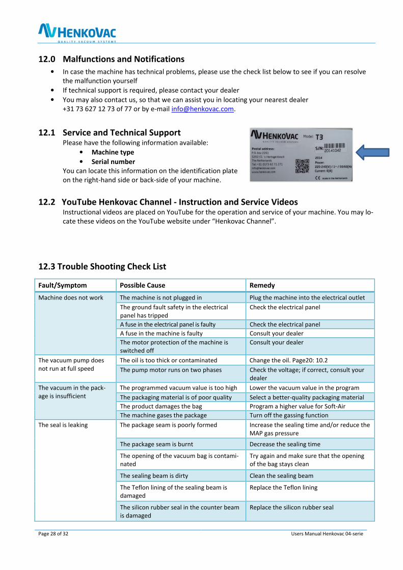
12.0 Malfunctions and Notifications
• In case the machine has technical problems, please use the check list below to see if you can resolve
the malfunction yourself
• If technical support is required, please contact your dealer
• You may also contact us, so that we can assist you in locating your nearest dealer
+31 73 627 12 73 of 77 or by e-mail [email protected].
12.1 Service and Technical Support Please have the following information available:
• Machine type
• Serial number You can locate this information on the identification plate
on the right-hand side or back-side of your machine. 12.2 YouTube Henkovac Channel - Instruction and Service Videos
Instructional videos are placed on YouTube for the operation and service of your machine. You may lo-
cate these videos on the YouTube website under “Henkovac Channel”.
12.3 Trouble Shooting Check List
Fault/Symptom Possible Cause Remedy
Machine does not work The machine is not plugged in Plug the machine into the electrical outlet
The ground fault safety in the electrical
panel has tripped
Check the electrical panel
A fuse in the electrical panel is faulty Check the electrical panel
A fuse in the machine is faulty Consult your dealer
The motor protection of the machine is
switched off
Consult your dealer
The vacuum pump does
not run at full speed
The oil is too thick or contaminated Change the oil. Page20: 10.2
The pump motor runs on two phases Check the voltage; if correct, consult your
dealer
The vacuum in the pack-
age is insufficient
The programmed vacuum value is too high Lower the vacuum value in the program
The packaging material is of poor quality Select a better-quality packaging material
The product damages the bag Program a higher value for Soft-Air
The machine gases the package Turn off the gassing function
The seal is leaking The package seam is poorly formed Increase the sealing time and/or reduce the
MAP gas pressure
The package seam is burnt Decrease the sealing time
The opening of the vacuum bag is contami-
nated
Try again and make sure that the opening
of the bag stays clean
The sealing beam is dirty Clean the sealing beam
The Teflon lining of the sealing beam is
damaged
Replace the Teflon lining
The silicon rubber seal in the counter beam
is damaged
Replace the silicon rubber seal

Users Manual Henkovac 04-serie Page 29 of 32
There is not enough gas in
the bag
The bag is too small Select a bigger bag
The programmed gas level is too low Increase the gas level value
The bag is not correctly positioned over the
gas outlets
Adjust the bag position
The machine does not seal The bag is not correctly positioned over the
sealing beam
Adjust the bag position
The sealing wire is broken Replace the sealing wire
The thermal safety of the power supply was
tripped
Wait until the safety resets, which can take
half an hour. Decrease the sealing time
The electrical contacts of the seal beam
have fouled
Remove the seal beam and clean the pins
and contacts with sand paper
The service symbol
appears when turn-
ing on the machine, indi-
cating the remaining pro-
duction hours or cycles
The service interval counters have reached
their maximum programmed values
To reset the service interval counters
after the oil change: Start machine
and while the display shows the hours
or cycles, press and hold the but-
ton
13.0 Recommended Spare Parts
Part No. Description
Seals
9705.00040 Silicon T-profile (Length 5mtr)
9705.00045 Sealing Wire 3,5 x 0,3 (Convex, length 5mtr)
9705.00050 Sealing Wire Ø1,1 (Clean Cut, length 5mtr)
9705.00055 Teflon Tape (Length 5mtr)
11.09.0.0040 Sealing Wire 5 x 0,2 (Flat)
11.09.0.0040 Sealing Wire 8 x 0,2 (Flat)
Pump Parts
03.01.1.0020 Oil exhaust filter for 021m3/h
03.01.0.0160 Oil exhaust filter for 016m3/h
03.01.1.0080 Oil exhaust filter for 040m3/h
03.01.1.0030 Oil exhaust filter for 063 and 100m3/h
03.01.1.0040 Oil exhaust filter for 160 and 300m3/h
03.01.1.0170 Oil filter for 040, 063 and 100m3/h
03.01.1.0060 Oil filter for 160 and 300m3/h
03.01.1.0220 Oil ISO VG32 (1 Ltr)
03.01.1.0120 Oil ISO VG100 (1 Ltr)
0301.00000 Oil ISO VG100 (1 Ltr) PRIVATE
Miscellaneous
9705.00035 Seal 8mm for transparent lid (Length 5mtr)
0504.00045 Silicone profile for stainless steel cover

Page 30 of 32 Users Manual Henkovac 04-serie
14.0 Utilities
Electrical
Voltage, current, frequency See identification plate
Maximum voltage tolerance - 10% to + 10%
Gas (optional)
Maximum allowable pressure 1 bar
Composition No explosive , corrosive, caustic and/or contami-
nated gases
Connection Hose coupling, 8mm for compressed air /
10mm for MAP gas
External sealing pressure (optional)
Maximum allowable pressure 1 bar
Composition Clean, dry compressed air
Connection Hose coupling, 8mm
14.1 General Data
Recommended Oil Types DIN 51506
Pumps
HLPT 22 4m3
VG032 8m3 - 16m3 - 21m3 1-phase pump
VG068 40m3 - 63m3 1-phase pump
VG 100 40m3 - 300m3 3-phase pump
Ambient Conditions
Ambient temperature + 5 to + 30° C / 41 to + 86° F
Transport temperature - 25 to + 55° C / - 13° F to + 131° F
Positioning Inside, level, unobstructed
15.0 Commonly-Used Symbols
The following pictograms and symbols are applied to your machine:
WARNING First consult the user manual regarding:
• Connecting the gas
• Connecting the compressed air
DANGER
• Risk for electric shock; before opening, remove the plug from the outlet
• Access by certified personnel only
Connection for compressed air
Connection for MAP gas

Users Manual Henkovac 04-serie Page 31 of 32
16.0 CE-DECLARATION OF CONFORMITY CE-KONFORMITÄTSERKLÄRUNG DECLARATION DE CONFORMITÉ CE DICHIARAZIONE DI CONFORMITA'CE Wij,
We, HFE Vacuum Systems bv.
Wir, Het Sterrenbeeld 36, 's-Hertogenbosch
Nous, The Netherlands
Noi,
verklaren geheel onder eigen verantwoordelijkheid dat de producten,
declare under our sole responsibility that the products,
erklären in alleiniger Verantwortung, daß die Produkte,
déclarons sous notre responsabilité, que les produits, Dichiariamo sotto la nostra responsabilità che las macchinas
Henkovac vacuum packing machines
waarop deze verklaring betrekking heeft, in overeenstemming is met de volgende Europese Richtlijnen:
to which this declaration relates, complies with the requirements of the following European Directives:
auf die sich diese Erklärung bezieht, folgende Europäischer Richtlinie entspricht:
auquel se réfère cette déclaration, est conforme aux Directives Européennes: alla quale si riferisce questa dichiarazione, è conforme alle Direttive Europee:
the machine guideline: 2006/ 42/EG the EMC-guideline: 2004/108/EG
Conformiteit is aangetoond door overeenstemming met de volgende normen:
Conformity is demonstrated by complete adherence to the following standards:
Die Übereinstimmung wird nachgewiesen durch die vollständige Einhaltung folgender Normen:
La conformité est demonstrée par la conformité intégrale avec les normes suivantes:
La conformità è dimostrata dalla conformità alle sequenti norme:
NEN-EN-ISO 12100-1 NEN-EN-ISO 12100-2 NEN-EN-ISO 14121-1 NEN-EN-ISO 13857 NEN-EN-ISO 60204-1
E.H. Goudsmid
Managing Director
The Netherlands, 's-Hertogenbosch, Januari 2014

Phone: +31 (0)73 6 271 271 e-mail: [email protected]
HFE Vacuum Systems bv. Het Sterrenbeeld 36 5215 ML `s Hertogenbosch The Netherlands
P.O. Box 2261 5202 CG `s Hertogenbosch The Netherlands