Vacuum Bag Only Processing of Complex Shapes: Effect of … · 2 ABSTRACT Out-of-autoclave prepregs...
16
2 ABSTRACT Out-of-autoclave prepregs can easily produce void-free flat laminates using vacuum bag-only consolidation in conventional ovens. However, the manufacture of parts with complex geometries is more challenging, because the relatively low consolidation pressure and the prepreg bulk factor can impede fiber bed compaction and porosity suppression. Previous studies have investigated the effect of various processing parameters on microstructural qualities, as well as the fabrication of L- shape laminates using different tool shapes and bagging configurations. This paper focuses on the effect of different corner angles (30°, 45°, and 60°) on part quality, and on their interaction with other common manufacturing parameters, including material properties, laminate thickness, processing conditions, and corner curvature. Cured laminate morphologies and microstructures are closely analyzed to assess part quality, including part thickness variation, resin distribution, and void content and distribution. This study shows that complex geometries can degrade part quality, but this effect is also influenced by materials and processing conditions. 1. INTRODUCTION Carbon fiber reinforced polymer composites have enabled the manufacture of aerospace parts with high strength and low density. Conventionally, composite parts are cured within pressure vessels called autoclaves, at high pressures and temperatures. The high applied pressures can ensure resin flow during cure, thus eliminating defects such as porosity by dissolving entrapped gases into solution or reducing void sizes [1]. In recent years, the high energy costs and infrastructural investments associated with autoclaves have led to the development of out-of-autoclave (OOA) prepreg processing. OOA processing can produce autoclave-quality parts using vacuum bag-only (VBO) _____________ Yijia Ma, Timotei Centea, Gaurav Nilakantan, Steven Nutt. M.C. Gill Composites Center, Viterbi School of Engineering, University of Southern California, 3651 Watt Way, VHE-412, Los Angeles, CA, 90089, United States Vacuum Bag Only Processing of Complex Shapes: Effect of Corner Angle, Material Properties and Processing Conditions Y. MA, T. CENTEA, G. NILAKANTAN and S. NUTT
Transcript of Vacuum Bag Only Processing of Complex Shapes: Effect of … · 2 ABSTRACT Out-of-autoclave prepregs...

2
ABSTRACT
Out-of-autoclave prepregs can easily produce void-free flat laminates using vacuum bag-only consolidation in conventional ovens. However, the manufacture of parts with complex geometries is more challenging, because the relatively low consolidation pressure and the prepreg bulk factor can impede fiber bed compaction and porosity suppression. Previous studies have investigated the effect of various processing parameters on microstructural qualities, as well as the fabrication of L-shape laminates using different tool shapes and bagging configurations. This paper focuses on the effect of different corner angles (30°, 45°, and 60°) on part quality, and on their interaction with other common manufacturing parameters, including material properties, laminate thickness, processing conditions, and corner curvature. Cured laminate morphologies and microstructures are closely analyzed to assess part quality, including part thickness variation, resin distribution, and void content and distribution. This study shows that complex geometries can degrade part quality, but this effect is also influenced by materials and processing conditions. 1. INTRODUCTION
Carbon fiber reinforced polymer composites have enabled the manufacture of aerospace parts with high strength and low density. Conventionally, composite parts are cured within pressure vessels called autoclaves, at high pressures and temperatures. The high applied pressures can ensure resin flow during cure, thus eliminating defects such as porosity by dissolving entrapped gases into solution or reducing void sizes [1]. In recent years, the high energy costs and infrastructural investments associated with autoclaves have led to the development of out-of-autoclave (OOA) prepreg processing. OOA processing can produce autoclave-quality parts using vacuum bag-only (VBO)
_____________
Yijia Ma, Timotei Centea, Gaurav Nilakantan, Steven Nutt. M.C. Gill Composites Center, Viterbi School of Engineering, University of Southern California, 3651 Watt Way, VHE-412, Los Angeles, CA, 90089, United States
Vacuum Bag Only Processing of Complex Shapes: Effect of Corner Angle, Material Properties and Processing Conditions Y. MA, T. CENTEA, G. NILAKANTAN and S. NUTT

3
consolidation while improving manufacture cost, energy efficiency and flexibility [2]. However, the relatively low pressure available for consolidation renders the manufacture of complex shape parts more challenging than within autoclaves. 1.1 Out of Autoclave Processing
VBO prepregs can be used to produce void-free parts by allowing the removal of air entrapped during prepreg lay-up, thereby reducing the number of void nucleation sites. Air evacuation is achieved through a partially impregnated microstructure consisting of dry, highly permeable regions (in most cases, the fiber tow cores) and resin-rich zones (inter-tow and inter-ply gaps) [3]. The dry tows/plies form a continuous network that allows gas migration to the laminate boundaries during a room temperature vacuum hold at the start of the manufacturing. At elevated temperatures, the network is infiltrated by surrounding resin.
Despite this distinctive microstructure, successful OOA prepreg processing remains prone to porosity if key material properties and processing parameters deviate from the allowable range. Previous studies have shown that high levels of absorbed moisture, low consolidation pressure or insufficient air evacuation time [4] may lead to pervasive gas-induced voids. Similarly, excessive out-time can increase the resin viscosity and prevent full tow impregnation, particularly when combined with slow ramp rates or low dwell temperatures [5]. These defect-causing phenomena are generally geometry-independent, and have been mostly studied in flat laminates. 1.2 Motivation for Complex Shape Laminates
Most aerospace composite parts have complex geometries due to features such as
interfaces, hollow sections and, most commonly, corners. Defects are more likely to occur in these areas than in flat sections due to defect sources that may not arise in flat parts, including challenging material placement during layup, uneven pressure distributions due to the tool geometry, and material and consumable bridging. Commonly-encountered defects include porosity, resin-rich zones, wrinkling and delamination, and dimensional instabilities such as thickness variations and resin accumulations [6]. Within angle laminates manufactured over concave (female) tools, resin tends to accumulate in the corner, resulting in corner thickening. However, laminates manufactured using convex (male) tools exhibited the opposite phenomenon, or corner thinning. Thickness variations can be caused by multiple phenomena, including pressure differences at the corner between the tool side and vacuum bag side and consumable bridging. In all cases, the specific mechanisms causing these defects must be understood, and feasible mitigation techniques must be developed and implemented to manufacture large, integrated structures.
Literature on the OOA manufacturing of complex parts using VBO prepregs is limited. The partial impregnation of OOA/VBO prepregs causes their bulk factor, or ratio of initial thickness to final thickness, to be higher than that of autoclave prepregs [7]. Thus, such materials exhibit a greater thickness change during processing than their traditional counterparts, and can be more susceptible to the defect-causing phenomena associated with corners. Brillant and Hubert [8] studied the consolidation of laminates containing a 90° angle for various laminate thicknesses and corner radii of curvature, on both male and female tools. They observed that corner consolidation
4
is influenced by the ratio of corner radius to laminate thickness, with lower ratios leading to lower quality. Cauberghs and Hubert [9] studied the consolidation of adjacent corner sections, and concluded that consumable bridging may occur due to the high bulk factor (or ratio of final thickness to initial thickness) inherent to VBO prepregs, but that corner quality may also be reduced by inter-ply shear. Grunenfelder et al. [10] studied the manufacturing a hat-stiffened structural element using VBO prepregs, and identified quality reductions at corner regions. Finally, Hughes and Hubert [11] studied size and complexity scale-up from lab-scale structures to an industrial demonstrator, and showed that the physical and manufacturing parameters governing part quality can interact to render industrial-scale manufacturing challenging.
1.3 Paper Objectives
This study seeks to expand existing knowledge on OOA/VBO manufacturing of
complex geometry structures by evaluating the effect of increasing geometric complexity on part quality. Specifically, it aims to assess the influence of increasing corner angle in a generic angle laminate in order to clarify the fundamental defect formation phenomena and the influence of key material properties and process parameters. In doing so, the study is expected to identify the allowable combinations of material, processing and geometry characteristics leading to high quality parts, and highlight useful strategies to reduce corner defects. 2. PROCEDURES
2.1 Materials
This study is carried out on two kinds of OOA prepreg designed for VBO
processing. Both are manufactured by Cytec Industries, and based on toughened epoxy matrices. The first consists of Cycom 5320 resin and a five harness satin (5HS) carbon fiber fabric (T650-35 6K). The second is comprised of Cycom 5320-1 resin and an eight harness satin (8HS) carbon fabric (T650-35 3K). The 5320-1 is a newer version of the 5320 resin, formulated for higher out-time, but both materials have comparable properties and processing characteristics. Both fabrics have areal weights of 375 g/m2. The 5320/5HS material used had significant freezer time and out-time, and was observed to have lower tack. In contrast, the 5320-1/8HS had low freezer time and negligible out-time. 2.2 Test Matrix
This paper presents manufacturing trials spanning several commonly encountered
part geometry characteristics, material properties, and processing conditions. The study was broadly divided into three parts. The first part considered the interplay between geometry, mold type and laminate thickness. Three typical corner angles (30°, 45°, 60°) were selected to observe the effect of progressive geometric complexity on part quality. Laminates of varying thickness levels (2 to 8 plies) were manufactured
5
TABLE I. TEST MATRIX Material Debulk Tool Shape Corner Radius
(mm) Corner Angle No. of
Plies 5320/5HS None Concave 0 30o, 45o, 60o 2, 4, 8
None Convex 0 30o, 45o, 60o 2, 4, 8 5320-1/8HS None Concave 0 30o, 45o, 60o 4, 8
None Convex 0 30o, 45o, 60o 4, 8 5320-1/8HS Yes Concave 0 30o, 45o, 60o 8
Yes Convex 0 30o, 45o, 60o 8 5320-1/8HS None Concave 9.53, 12.7 30o, 45o, 60o 8
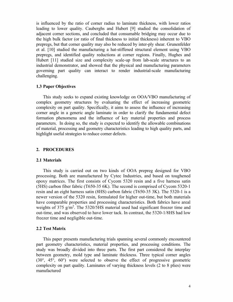
None Convex 6.35, 9.53 30o, 45o, 60o 8 over concave (female) and convex (male) aluminum molds using the two kinds of woven prepreg, to determine scale effects on the studied phenomena and properties. The second part considered the additional influence of intermediate debulking method for thick laminates. In this case, 5 minute vacuum consolidation was applied every 2 plies for 8-ply 5320-1/8HS laminates. Both concave and convex tools were studied for 30°, 45° and 60° corners. The third part considered the specific influence of mold corner curvature for 8-ply laminates made of 5320-1/8HS. Four corner radii of curvature, ranging from sharp (0 mm) to rounded (12.7 mm), were studied. The full test matrix, and the specific combinations of material properties and process parameters are shown in TABLE I. Laminates were measured 76 mm by 63.5 mm by 63.5 mm, as shown in Figure 1. 2.3 Layup and Bagging
Figure 2 presents the schematics of the two types of aluminum molds used in this study.
The sharp corner molds, shown as Figure 2 (i), consist of corner blocks and a flat tool plate. Both components are well
matched, and dowel pins are used to fix the prisms to the tool plate. The molds with rounded corners, shown in
Figure 2 (ii), have integrated flat regions. While multiple corner laminates were sometimes manufactured on each mold, each part was laid up over individual corners
separately, as shown in Figure 2 (i).
63.5 mm
63.5 mm
76 mm

6
Figure 1. Laminate dimensions
Figure 2. Aluminum molds with i) Sharp corner and ii) Corner curvature
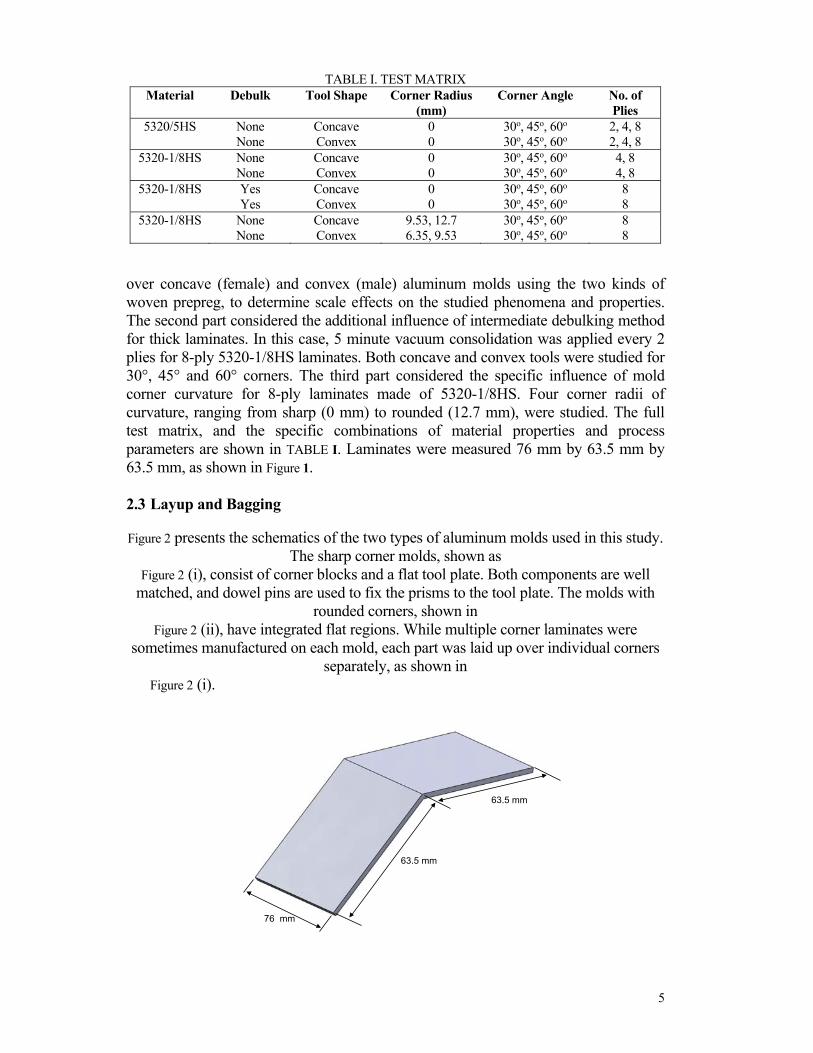
The four typical stages of manufacturing are presented in Figure 3. First, the polished aluminum molds were cleaned using acetone. Non-perforated release film (Airtech A4000) was laid down to the mold prior to prepreg lay-up for easy removal of cured laminates. The prepreg plies were laid down in a [0°]n layup, where 0° denotes the corner direction and n denotes the number of plies. Edge breathing dams made of sealant tape wrapped in fiberglass boat cloth were then placed around the laminate boundaries to provide a pathway for air evacuation. A second layer of non-perforated release film was placed over the laminate, under two plies of breather fabric (Airtech Airweave N10). Finally, the entire assembly was covered in a vacuum bag (Airtech Wrightlon 8400) and sealant tape (Airtech GS213). A leak test was performed to ensure bag integrity, and vacuum was drawn in the bag.
7
Figure 3. Manufacturing procedures: i) Prepreg layup; ii) Vacuum bagging; iii) Room temperature vacuum hold; iv) Cured laminate sections.
The cure cycle consisted of a four-hour room temperature vacuum hold, as directed by the Cycom 5320 and 5320-1 data sheets, followed by a 2°C/min ramp and a 121°C dwell of two hours for the 5320 laminates and three hours for the 5320-1. In all cases, bag pressures were below 4% of atmospheric (4000 kPa or 28.5” Hg). 2.4 Analysis 2.4.1 SAMPLE PREPARATION
Two sample sections were excised from each cured laminate, as shown in Figure 3 (iv). The two cross-sectional areas facing the middle of the laminate (as indicated in the picture) were then polished to 2400 grit using a metallographic grinder/polisher (Buehler MetaServ). Then, optical micrographs of the entire cross-section were captured using digital microscope (Keyence VHX-600) at 100X magnification. Finally, individual micrographs were stitched into a large image of the cross-section. 2.4.2 VOID CONTENT MEASUREMENT
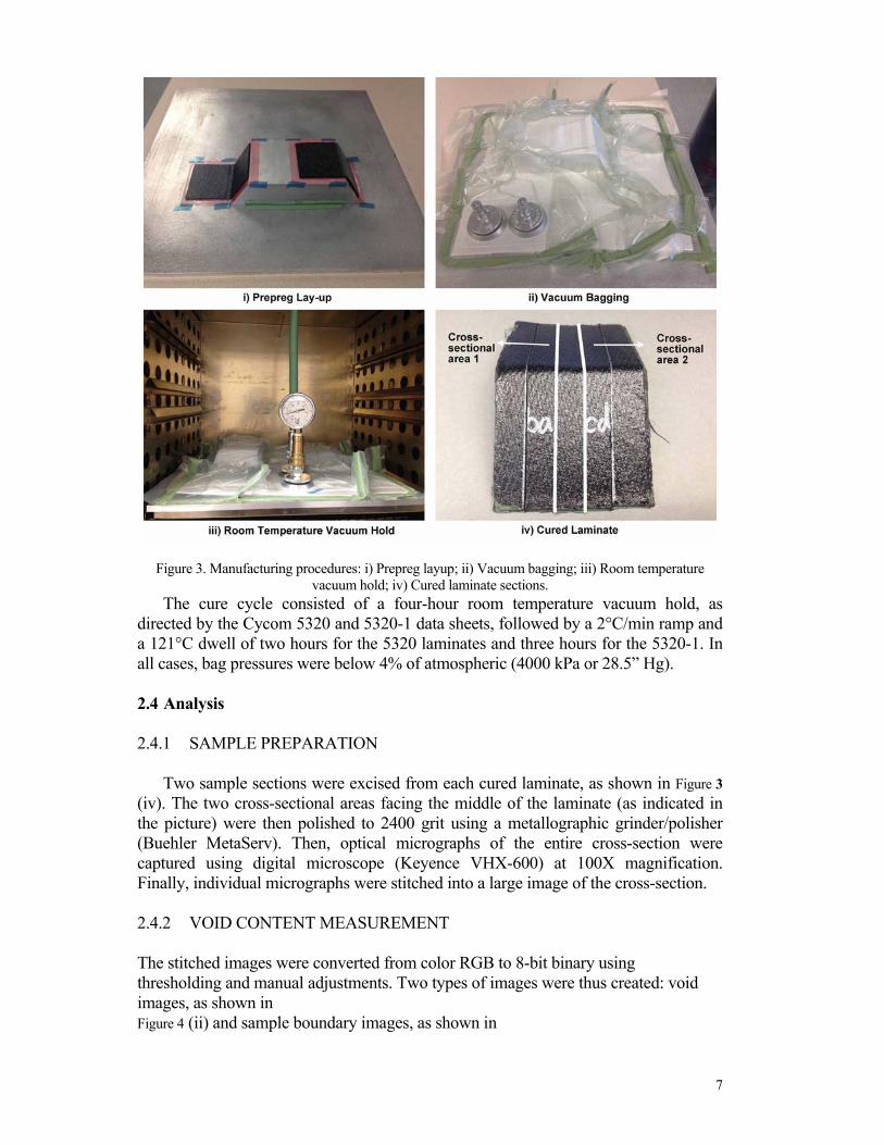
The stitched images were converted from color RGB to 8-bit binary using thresholding and manual adjustments. Two types of images were thus created: void images, as shown in Figure 4 (ii) and sample boundary images, as shown in
8
Figure 4 (iii). Void contents were calculated using the ImageJ scientific image analysis program from the binary pictures. The flange and corner regions were also analyzed separately, to identify local differences. In all cases, void contents were calculated as the ratio of the total void area over the laminate area.
2.4.3 THICKNESS VARIATION
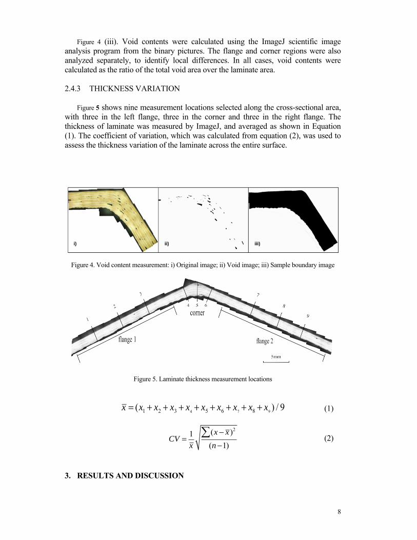
Figure 5 shows nine measurement locations selected along the cross-sectional area,
with three in the left flange, three in the corner and three in the right flange. The thickness of laminate was measured by ImageJ, and averaged as shown in Equation (1). The coefficient of variation, which was calculated from equation (2), was used to assess the thickness variation of the laminate across the entire surface.
Figure 4. Void content measurement: i) Original image; ii) Void image; iii) Sample boundary image
Figure 5. Laminate thickness measurement locations x = (x1 + x2 + x3 + x4 + x5 + x6 + x7 + x8 + x9 ) / 9 (1)
CV = 1x
(x − x )2(n −1)
(2)
3. RESULTS AND DISCUSSION

9
3.1 Defect Types
Figure 6 shows the four types of defects observed in this study. Delaminations between different plies were observed, but only in isolated situations. Their cause was not clearly determined, but they are likely outliers. Voids were commonly seen in most laminates, though void content levels varied. Concave corners exhibited corner thickening due to resin accumulation. Conversely, corner thinning was observed in convex corners. 3.2 Effect of Corner Angle and Ply Thickness
The effect of corner angle (30o, 45o, 60o) and ply thickness (2, 4, and 8 plies) were studied for laminates made of 5320/5HS and 5320-1/8HS. As previously noted, no intermediate debulking was used during layup, and all corner angles were sharp (0 mm radius of curvature). 3.2.1 VOID CONTENT
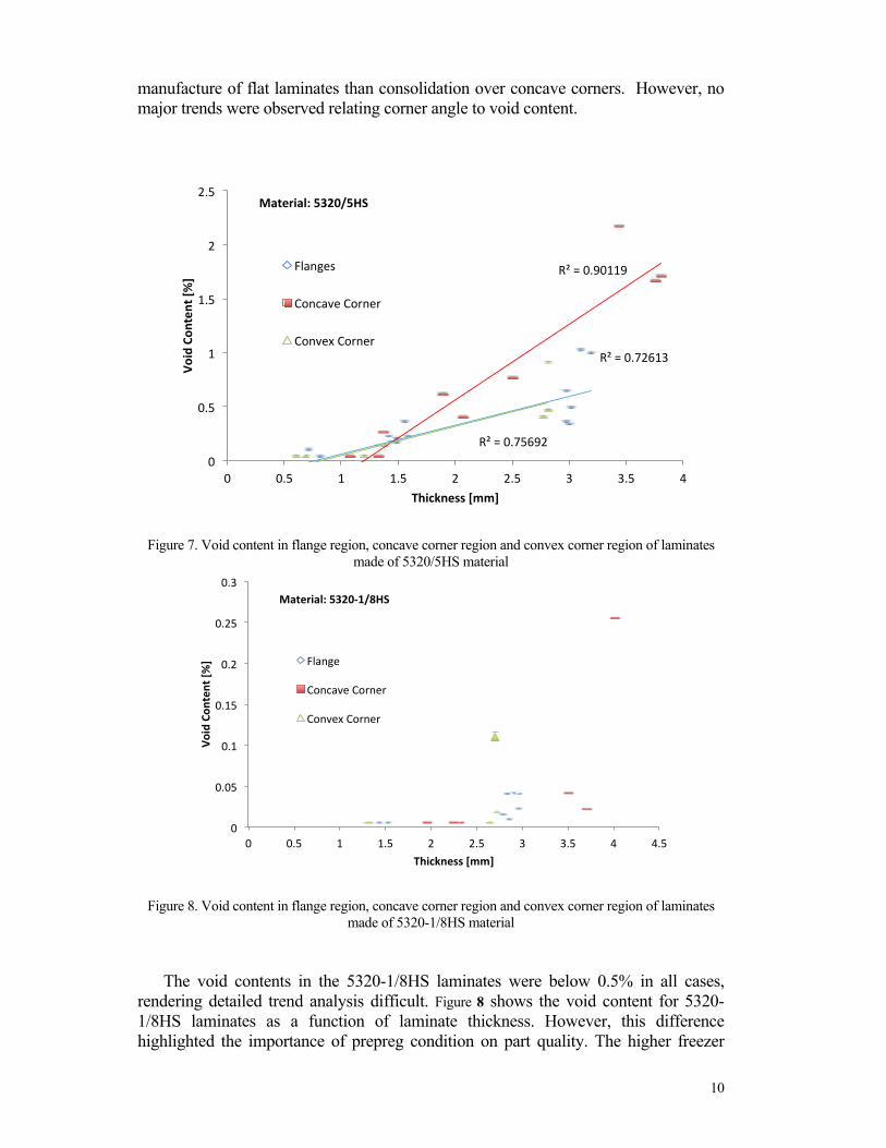
Figure 7 shows the void content for all 5320/5HS laminates as a function of laminate thickness (number of plies) in the flange, concave corner and convex corner regions. In all cases, the void content was observed to increase with laminate thickness, in a reasonably linear manner. In concave corner regions, the porosity increased faster with thickness than for either the convex corner or the flat flanges. However, in convex corners, the rate of increase was identical to that observed in the flanges, suggesting that consolidation over convex corners is less different from the
Figure 6. Main defects in the cured laminates: i) Delaminations, ii) Voids, iii) Corner thickening, iv) Corner thinning
10
manufacture of flat laminates than consolidation over concave corners. However, no major trends were observed relating corner angle to void content.
Figure 7. Void content in flange region, concave corner region and convex corner region of laminates made of 5320/5HS material
Figure 8. Void content in flange region, concave corner region and convex corner region of laminates made of 5320-1/8HS material
The void contents in the 5320-1/8HS laminates were below 0.5% in all cases, rendering detailed trend analysis difficult. Figure 8 shows the void content for 5320-1/8HS laminates as a function of laminate thickness. However, this difference highlighted the importance of prepreg condition on part quality. The higher freezer
R² = 0.72613
R² = 0.90119
R² = 0.75692 0
0.5
1
1.5
2
2.5
0 0.5 1 1.5 2 2.5 3 3.5 4
Void
Con
tent
[%]
Thickness [mm]
Flanges
Concave Corner
Convex Corner
Material: 5320/5HS
0
0.05
0.1
0.15
0.2
0.25
0.3
0 0.5 1 1.5 2 2.5 3 3.5 4 4.5
Void
Con
tent
[%]
Thickness [mm]
Flange
Concave Corner
Convex Corner
Material: 5320-1/8HS

11
time and out-time of the 5320-based prepreg reduced tack and increased the resin viscosity, thus impeding intimate ply adhesion and void migration. 3.2.2 THICKNESS VARIATION
The thickness variation induced by different angles in concave and convex corners that were made of 5320/5HS is presented in
Figure 9. The variation across the cross-section was much larger in concave compared to convex corners. Furthermore, as the corner angle increased, the thickness variation in concave corners increased in a quasi-linear manner for all three laminate thicknesses. In convex corners, no such trend was observed, with the coefficient of variation decreasing for two ply laminates and remaining relatively consistent for four and eight ply laminates. Finally, as the laminate thickness increased, the coefficient of variation decreased for all corner angles and for both concave and convex molds, suggesting that thickness uniformity was easier to achieve in thicker laminates.
Resin accumulation in the concave corner is one source that causes thickness variation of laminates. Thus, the thickness variation can also be analyzed specifically in terms of corner resin length, defined as the length of the resin accumulated in the concave corner facing the tool side (Figure 5 (iii)). This defect type was observed exclusively in concave corners.
This resin accumulation is attributed to the lower consolidation pressure experienced by concave corners due to the tool geometry (and the through-thickness pressure differences) as well as by possible material and consumable bridging (though, in this study, laminates were carefully laid up and bagged to limit both effects).
Figure 9. Thickness variation of laminates made of 5320/5HS material
Figure 10 shows the length of resin accumulated at the concave corner on the tool side. There was no increasing trend of the corner resin length with corner angle, which we expected to observe based on the coefficient of variation. In laminates made of 5320/5HS, not all resin migrated into the tool side of the corner. The vacuum bag side
0
0.1
0.2
0.3
0.4
0.5
30° Corner 45° Corner 60° Corner 30° Corner 45° Corner 60° Corner
Coeffic
i
ent o
f Varia
on [-]
2 Plies 4 Plies 8 Plies
Material: 5320/5HS
Concave Corners (female)
Convex Corners (male)

12
of the corner also had some resin accumulation because of the increased viscosity of 5320/5HS due to its long freezer time and out-time.
Broadly similar trends were observed for the 5320-1/8HS laminates, as shown in Figure 11. However, the overall thickness variation was slightly less pronounced in both concave and convex corner laminates. This reduction is attributed in part to the shorter out-time of the 5320-1/8HS, which may allow the resin to flow more easily than the 5320/5HS. In addition, the discrepancy can also be explained by the lower void content of the 5320-1/8HS laminates.
Figure 10. Corner resin length in concave corners made of 5320/5HS material
Figure 11. Thickness variation of laminates made of 5320-1/8HS material
Corner resin length of laminates manufactured of 5320-1/8HS is shown in Figure 12. Unlike 5320/5HS, the change in corner resin length with corner angle
was similar to that of the coefficient of variation: higher corner angles increase the level of resin accumulation and consequently, the laminate thickness at the corner. Because of the shorter freezer time and out-time, the resin accumulation of 5320-1/8HS mainly occured in the tool side region of the concave corner.
0
0.2
0.4
0.6
0.8
1
30° Corner 45° Corner 60° Corner
Corner
Resin
Leng
th [m
m]
Concave Corner-2 Plies Concave Corner-4 Plies Concave Corner-8 Plies
Material: 5320/5HS
0
0.1
0.2
0.3
0.4
0.5
30° Corner 45° Corner 60° Corner 30° Corner 45° Corner 60° Corner
Coeffic
i
ent o
f Varia
on [-]
4 Plies 8 Plies
Concave Corners (female)
Convex Corners (male)
Material: 5320-1/8HS

13
The correlation between coefficient of variation and corner resin length suggests that the major source of thickness variation in concave corners is the resin accumulation. 3.3 Effect of Debulking
The effect of intermediate vacuum debulking (five minutes of vacuum hold every two plies) was investigated on 5320-1/8HS laminates made up of eight plies. All three corner angles were studied, and the corners had sharp radii. As shown in Figure 13,
Figure 12. Corner resin length in concave corners made of 5320-1/8HS material
Figure 13. Thickness variation of laminates manufactured without debulking and with debulking debulking had a relatively minor effect on the coefficient of variation of the thickness, or the thickness uniformity. In most cases, the coefficient of variation decreased, but
only by a small amount when compared to the effect of corner angle. Figure 14 presents the measured corner resin lengths in concave laminates of two debulking methods. Debulking did not significantly affect the corner resin length, which agreed with the very slightly changed coefficient of variation in laminates with
0.00
0.40
0.80
1.20
1.60
30° Corner 45° Corner 60° Corner
Corner
Resin
Length
[mm]
Concave Corner-4 Plies Concave Corner-8 Plies
Material: 5320-1/8HS
0
0.05
0.1
0.15
0.2
0.25
0.3
30° Corner 45° Corner 60° Corner 30° Corner 45° Corner 60° Corner
Coeffic
i
ent o
f Varia
on [-]
Without Debulking With Debulking
No. of Plies: 8 plies
Concave Corners (female)
Convex Corners (male)

14
and without debulking. This again shows that the method of investigating corner resin length can be used as an accurate and simpler way to measure thickness variation of laminates. 3.4 Effect Of Corner Curvature
The effect of corner curvature was studied on laminates made of 8 plies of 5320-1/8HS. No intermediate debulking was used, and all three corner types were
Figure 14. Corner resin length in concave corners manufactured without debulking and with debulking
Figure 15. Thickness variation of laminates manufactured using molds with sharp corner and with corner curvature
studied. Mold corner radii of 9.53 mm and 12.7 mm were selected for the concave corners, while 6.35 mm and 9.53 mm radii were used for the convex corners. Larger corner radii were imposed on concave corners due to the comparatively higher defect
levels observed on such tooling. Figure 15 shows that the coefficients of variation of thickness for laminates produced with convex tooling remained less than those of laminates made on concave tooling,
0
0.4
0.8
1.2
1.6
2
30° Corner 45° Corner 60° Corner
Corner
Resin
Lenth [m
m]
Without Debulking With Debulking
No. of Plies: 8 plies
0
0.05
0.1
0.15
0.2
0.25
0.3
30° Corner 45° Corner 60° Corner 30° Corner 45° Corner 60° Corner
Coeffic
i
ent o
f Varia
on [-]
Corner Radius: 0 Corner Radius: 9.53 mm
Concave Corners (female)
Convex Corners (male)
Material: 5320-1/8HS

15
even for the same corner radius (9.53 mm). Thus, convex corner tooling was again observed to be more robust, and less likely to produce inferior parts.
For concave tools, the laminate thickness variation decreased in a quasi-linear manner with increasing corner radius, as shown in Figure 16. The same decreasing trend was also observed for convex tools in Figure 17, but in a less pronounced manner.
Figure 16. Thickness variation of concave corner laminates manufactured with various corner curvatures
Figure 17. Thickness variation of convex corner laminates manufactured with various corner curvatures
4. CONCLUSIONS In this study, OOA prepreg laminates with different corner geometries were
manufactured using VBO processing. The effect of corner angles (30o, 45o, and 60o), prepreg material (5320/5HS and 5320-1/8HS), laminate thickness (2 plies to 8 plies), intermediate debulking method (none and five minute vacuum hold every two plies), and corner curvature (0 mm to 12.7 mm) on laminate quality were investigated in terms of void content and dimensional uniformity.
0
0.05
0.1
0.15
0.2
0.25
0 0.1 0.2 0.3 0.4 0.5 0.6
Coeffic
ent o
f Varia
on [-]
Corner Radius [mm]
30° Corner 45° Corner 60° Corner
Concave Corner
0
0.01
0.02
0.03
0.04
0.05
0.06
0 0.05 0.1 0.15 0.2 0.25 0.3 0.35 0.4
Coeffic
ent o
f Varia
on [-]
Corner Radius [mm]
30° Corner 45° Corner 60° Corne
Convex Corner

16
Several conclusions are drawn. Geometric complexity can lead to a decrease in quality, both in terms of increased porosity and thickness variability. However, the magnitude of this decrease is dependent on several other factors. For the same level of geometric complexity (here, corner angle), consolidation over concave tools consistently leads to considerably higher void contents and larger thickness deviations than convex tools. Both defects are associated, for these material systems, with reduced compaction and resin accumulation at the concave corner. Conversely, on convex tools, increasing geometric complexity does not always produce lower-quality parts. Prepreg properties such as tack and resin viscosity (here, affected by freezer time and out-time) can vary baseline quality levels by affecting ply adhesion and nesting, and older prepregs may produce lower quality laminates in all conditions.
By considering these factors synergistically, a range of allowable material and process conditions can be identified. For example, for a laminate of given thickness and a desired thickness uniformity, a maximum corner angle can be identified. Similarly, for an existing tool with a given corner radius, a minimum thickness variation and/or resin accumulation level can have to be incurred. By the same method, defect mitigation strategies can be identified. For example, for a given design comprising a prepreg material, a layup and structural dimensions, tooling of appropriate type and with sufficient corner curvature can be designed. If convex tooling is required, lower curvature may be allowable for the same part quality. If concave tooling is needed, higher curvatures can be imposed.
Several phenomena associated with complex geometries nevertheless remain to be clarified. The precise mechanisms by which concave corners reduce quality in OOA/VBO prepregs, and specifically the exact influence of the partially impregnated microstructure, bulk factor and eventual impregnation flow are not fully understood. In addition, the scale effects associated with the size of individual part elements (flange, corners) and overall part size have not been studied. Finally, the effect of geometric complexity scale-up (to structures such as hat stiffeners) must be investigated.
5. ACKNOWLEDGEMENTS This project is funded by the National Science Foundation G8 Research Project of
Interdisciplinary Program on Material Efficiency, through the “Sustainable Manufacturing: Out-of-Autoclave Processing” project (CMMI-1229011). Cytec Industries generously donated the materials used in this study, and Airtech International donates the consumables. The authors would like to thank Garrett Peters, an undergraduate research assistant, for his sample analysis work and helpful suggestions. Finally, the helpful contributions and suggestions of the G8 project’s academic partners and industrial advisory board are gratefully acknowledged.
REFERENCES 1. Campbell, F.C. 2006. “Manufacturing Technology for Aerospace Structural Materials,” London:,
Elsevier.

17
2. Ridgard, C. 2009. "Out of Autoclave Composite Technology for Aerospace, Defense and Space Structures," in Proceedings of the SAMPE 2009 Conference of the Society for the Advancement of Materials and Process Engineering.
3. Centea, T. and Hubert, P. 2011. "Measuring the impregnation of an out-of-autoclave prepreg by micro-CT," Composites Science and Technology, 71(5): 593-599.
4. Grunenfelder, L.K. and Nutt, S.R. 2010. "Void formation in composite prepregs - Effect of dissolved moisture," Composites Science and Technology, 70(16): 2304-2309.
5. Grunenfelder, L.K., Centea, T., Hubert, P., and Nutt, S.R. 2013. "Effect of room-temperature out-time on tow impregnation in an out-of-autoclave prepreg," Composites Part A: Applied Science and Manufacturing, 45(0): 119-126.
6. Hubert, P. and Poursartip, A. 2001. "Aspects of the Compaction of Composite Angle Laminates: An Experimental Investigation," Journal of Composite Materials, 35(1 ): 2-26.
7. Centea, T. and Hubert, P. 2013. "Out-of-autoclave prepreg consolidation under deficient pressure conditions," Journal of Composite Materials.
8. Brillant, M. and Hubert, P. 2010. "Out-of-autoclave processing of complex shape laminates," in Proceedings of the SAMPE 2010 Conference of the Society for the Advancement of Materials and Process Engineering, Society for the Advancement of Materials and Process Engineering.
9. Cauberghs, J. and Hubert, P. 2011. "Effect of tight corners and ply terminations on quality in out-of-autoclave parts," in Proceedings of the SAMPE 2011 Conference of the Society for the Advancement of Materials and Process Engineering, Society for the Advancement of Materials and Process Engineering.
10. Grunenfelder, L.K., Fisher, C., Cabble, C., Thomas, S., and Nutt, S.R. 2012. "Defect control in out-of-autoclave manufacturing of structural elements," in Proceedings of the SAMPE 2012 Technical Conference.
11. Hughes, S.M. and Hubert, P. 2013. "Out-of-autoclave prepreg processing: Effect of integrated geometric effects on part quality," SAMPE Technical Conference.