vacon 100 industrial vacon 100 flow vacon 100 hvac vacon...
35
vacon 100 industrial vacon 100 flow vacon 100 hvac vacon 100 x ac drives i/o option boards type ‘b’ and ‘f’ user manual ® ® ® ®
Transcript of vacon 100 industrial vacon 100 flow vacon 100 hvac vacon...

vacon 100 industrialvacon 100 flowvacon 100 hvac
vacon 100 xac drives
i/o option boards type ‘b’ and ‘f’user manual
®
®
®
®

vacon • 1
24-hour support +358 (0)201 212 575 • Email: [email protected]
TABLE OF CONTENTS
Document: DPD00211C
Release date : 25/1/16
1. General information.........................................................................................21.1 Board slots on Vacon 100...................................................................................................21.2 Option board type B............................................................................................................31.2.1 Board type B technical data...............................................................................................31.2.2 Isolation..............................................................................................................................31.2.3 Analogue inputs .................................................................................................................41.2.4 Analogue outputs ...............................................................................................................41.2.5 Control voltage (+24V/ext +24V) .........................................................................................41.2.6 Digital input signal conversions.........................................................................................41.3 Hardware protections ........................................................................................................71.3.1 Terminal block coding .......................................................................................................71.4 Type identification number ................................................................................................71.5 Defining functions to inputs and outputs - programming.................................................71.5.1 Example programming ......................................................................................................72. Installation of option boards ............................................................................92.1 Vacon 100, Vacon 100 FLOW and Vacon 100 HVAC............................................................92.2 Vacon 100 X ......................................................................................................................112.3 Prepare for use ................................................................................................................152.4 Control cables ..................................................................................................................172.5 Board information sticker................................................................................................173. Description of type ‘B’ and ‘F’ boards.............................................................183.1 Board OPTB1....................................................................................................................193.1.1 I/O terminals on OPTB1 ...................................................................................................193.1.2 Jumper selections............................................................................................................203.2 Board OPTB2....................................................................................................................213.2.1 I/O terminals on OPTB2 ...................................................................................................213.3 Board OPTB4....................................................................................................................223.3.1 I/O terminals on OPTB4 ...................................................................................................223.4 Board OPTB5....................................................................................................................233.4.1 I/O terminals on OPTB5 ...................................................................................................233.5 Board OPTB9....................................................................................................................243.5.1 I/O terminals on OPTB9 ...................................................................................................243.6 Board OPTBF....................................................................................................................253.6.1 I/O terminals on OPTBF ...................................................................................................253.6.2 Jumper selections............................................................................................................263.7 Board OPTBH ...................................................................................................................273.7.1 I/O Terminals on OPTBH..................................................................................................273.7.2 OPTBH accuracy...............................................................................................................283.7.3 OPTBH option board wiring scheme: ..............................................................................293.7.4 OPTBH board parameters ...............................................................................................293.8 Boards OPTF3 and OPTF4................................................................................................303.8.1 I/O terminals on OPTF3 and OPTF4 boards.....................................................................31
1
vacon • 2 General information
1. GENERAL INFORMATION
Vacon 100 product range embodies a wide selection of expander boards with which the available I/O of the AC drive can be increased and its versatility improved.
The input and output configuration (I/O) of Vacon 100 is designed with modularity in mind. The total I/O is comprised of basic and option boards, each having its own input and output configuration. The boards contain analogue and digital inputs and outputs and additional application-specific hard-ware.
The option boards are placed in the board slots on the AC drive. The I/O boards are usually inter-changeable between different drive types, i.e. Vacon 100 and Vacon NX series. However, the control boards of these types differ from each other to some extent which means that the use of some I/O boards in different Vacon AC drive types may be restricted.
1.1 Board slots on Vacon 100
The control board is situated inside the control unit of the Vacon 100 drive. There are two board slots (labelled D and E) on the Vacon 100X control board and three board slots (labelled C, D and E) on the Vacon 100, Vacon 100 FLOW and Vacon 100 HVAC control board. To locate the slots, see page 10. See also the descriptions of the option boards in Chapter 3.
Usually, when the AC drive is delivered from the factory, the control unit includes at least the stan-dard board, which is installed in the standard board slot. The I/O boards mounted at the factory are indicated in the type code of the AC drive. The expander slots D, E (Vacon100X) and C, D, E (Vacon 100, Vacon 100 FLOW, Vacon 100 HVAC) are available for different option boards.
NOTE! You can download the English and French product manuals with applicable safety, warning and caution information fromhttp://drives.danfoss.com/knowledge-center/technical-documentation/.
REMARQUE Vous pouvez télécharger les versions anglaise et française des manuels produit contenant l’ensemble des informations de sécurité, avertissements et mises en garde applicables sur le site http://drives.danfoss.com/knowledge-center/technical-documentation/.
Tel. +358 (0) 201 2121 • Fax +358 (0)201 212 205
General information vacon • 3
1.2 Option board type B
Type B option boards are used for I/O expansion. They are interchangeable with the boards of the same type used in Vacon NX series.
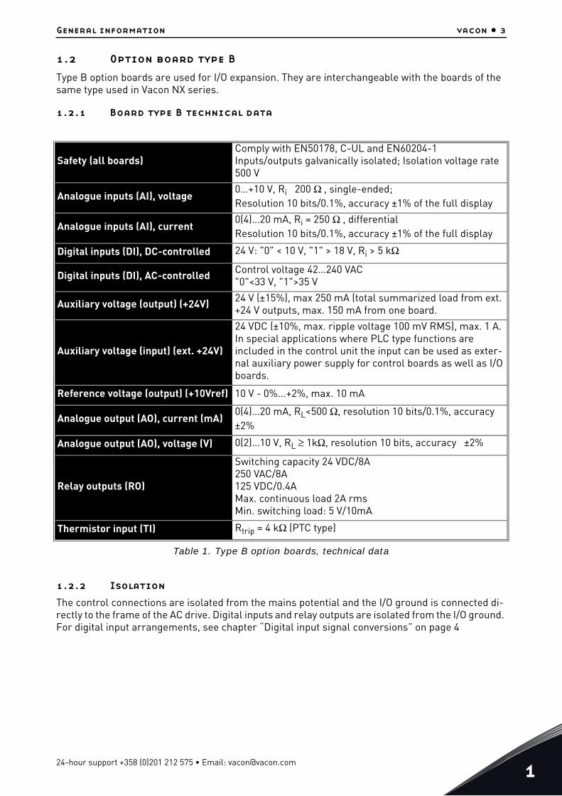
1.2.1 Board type B technical data
Table 1. Type B option boards, technical data
1.2.2 Isolation
The control connections are isolated from the mains potential and the I/O ground is connected di-rectly to the frame of the AC drive. Digital inputs and relay outputs are isolated from the I/O ground. For digital input arrangements, see chapter “Digital input signal conversions” on page 4
Safety (all boards)Comply with EN50178, C-UL and EN60204-1Inputs/outputs galvanically isolated; Isolation voltage rate 500 V
Analogue inputs (AI), voltage0…+10 V, Ri 200 Ω , single-ended;Resolution 10 bits/0.1%, accuracy ±1% of the full display
Analogue inputs (AI), current0(4)…20 mA, Ri = 250 Ω , differentialResolution 10 bits/0.1%, accuracy ±1% of the full display
Digital inputs (DI), DC-controlled 24 V: "0" < 10 V, "1" > 18 V, Ri > 5 kΩ
Digital inputs (DI), AC-controlled Control voltage 42…240 VAC"0"<33 V, "1">35 V
Auxiliary voltage (output) (+24V) 24 V (±15%), max 250 mA (total summarized load from ext. +24 V outputs, max. 150 mA from one board.
Auxiliary voltage (input) (ext. +24V)
24 VDC (±10%, max. ripple voltage 100 mV RMS), max. 1 A.In special applications where PLC type functions are included in the control unit the input can be used as exter-nal auxiliary power supply for control boards as well as I/O boards.
Reference voltage (output) (+10Vref) 10 V - 0%...+2%, max. 10 mA
Analogue output (AO), current (mA)0(4)…20 mA, RL<500 Ω, resolution 10 bits/0.1%, accuracy ±2%
Analogue output (AO), voltage (V) 0(2)…10 V, RL ≥ 1kΩ, resolution 10 bits, accuracy ±2%
Relay outputs (RO)
Switching capacity 24 VDC/8A250 VAC/8A125 VDC/0.4AMax. continuous load 2A rmsMin. switching load: 5 V/10mA
Thermistor input (TI) Rtrip = 4 kΩ (PTC type)
24-hour support +358 (0)201 212 575 • Email: [email protected]
1
vacon • 4 General information
1.2.3 Analogue inputs
The analogue inputs of the type B boards can be used as either current inputs or voltage (mA/V) in-puts (see detailed description of each board). The signal type is selected with a jumper block (B-type boards), or a dip switch (F-type boards) on the board. In case the voltage type input is used you still have to define the voltage range with another jumper block/dip switch. The factory default value for the analogue signal type is given in the description of the board. For detailed information, see the description of the board in question.
1.2.4 Analogue outputs
The analogue outputs of option boards of type B are used with current (mA) signal only. However, on some certain option boards the signal type (mA/V) can be selected with a jumper/dip switch. See more detailed information on individual boards in chapter 3.
1.2.5 Control voltage (+24V/ext +24V)
The control voltage output +24 V/EXT+24 V can be used in two ways. Typically, the +24 V control volt-age is wired to digital inputs through an external switch. The control voltage can also be used to power-up external equipment, such as encoders and auxiliary relays.
Observe that the specified total load on all available +24 V/EXT+24V output terminals must not ex-ceed 250 mA.
The +24 V/EXT+24 V outputs can further be used to externally power up the control board as well as option boards. If an external power supply is connected to EXT+24 V output, the control board and option boards remain live even if mains should be lost on the AC drive. This ensures sufficient func-tioning of the control logic (not the motor control, however) and some alarms in exceptional power-loss situations. Furthermore, fieldbus links remain powered which enables e.g. the Fieldbus Mas-ter to read valuable data on the AC drive. NOTE: The power unit is not powered through the EXT+24 V and therefore the motor control does not work if the mains is lost.
Requirements for an external power back-up:
• output voltage +24DC±10%, max. ripple voltage 100 mV RMS• max. current 1A• 1A external fuse (no internal short-circuit protection on the control board)
NOTE: Analogue outputs and inputs do not work with only +24 V supplied to the control unit.
If there is a +24 V/EXT+24V output on the board it is short-circuit protected locally. Should one of the +24 V/EXT+24 V outputs shortcircuit, the others would remain powered because of the local pro-tection.
1.2.6 Digital input signal conversions
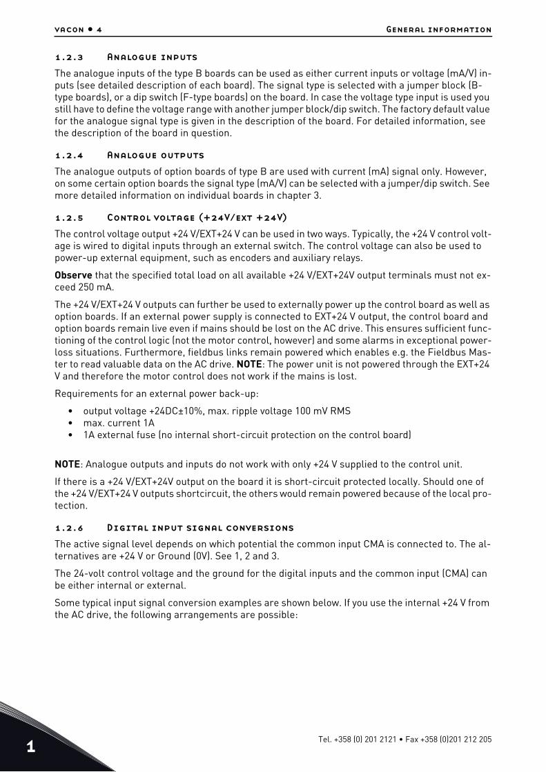
The active signal level depends on which potential the common input CMA is connected to. The al-ternatives are +24 V or Ground (0V). See 1, 2 and 3.
The 24-volt control voltage and the ground for the digital inputs and the common input (CMA) can be either internal or external.
Some typical input signal conversion examples are shown below. If you use the internal +24 V from the AC drive, the following arrangements are possible:
Tel. +358 (0) 201 2121 • Fax +358 (0)201 212 205
General information vacon • 5
Figure 1. If CMA is connected to GND with inboard jumper the internal +24 V is used and the CMA terminal need not be wired
Figure 2. Positive logic with external +24 V when CMA is isolated from GND using onboard jum-per. The input is active when the switch is closed.
+24V/EXT+24V
DI1
DI2
DI3...DI6
GND
7115.emf
CMA connected to GNDJumper installed =
+24V/EXT+24V
DI1
DI2
DI3...DI6
GND
7116.emf
= CMA isolated from GND
Ground
External +24V
Jumper not installed
24-hour support +358 (0)201 212 575 • Email: [email protected]
1
vacon • 6 General information
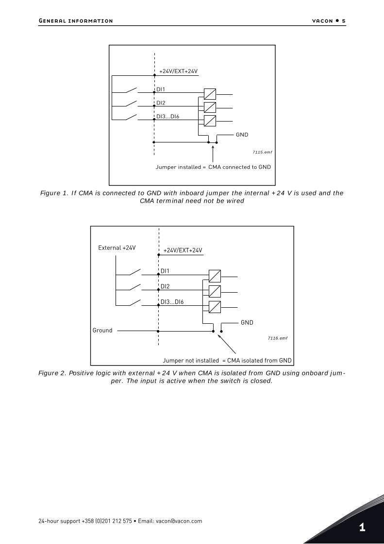
Figure 3. Negative logic with external +24 V when CMA is isolated with onboard jumper. The input is active when the switch is closed (0V is the active signal).
You can make the positive and negative logic arrangements also with the internal +24 V. Place the jumper block in the 'CMA isolated from GND' position (as above) and wire the CMA terminal to the GND terminal of the AC drive.
+24V/EXT+24V
DI1
DI2
DI3...DI6
GND
7117.emf
= CMA isolated from GND
External +24V
Ground
Jumper not installed
Tel. +358 (0) 201 2121 • Fax +358 (0)201 212 205
General information vacon • 7
1.3 Hardware protections
1.3.1 Terminal block coding
In order to avoid incorrect connections of terminal blocks to boards, some terminal blocks as well as related terminal connectors on the board are uniquely coded. For more information, see the de-scription of the individual board.
1.4 Type identification number
NOTE: This information is relevant only for special applications designers using the Vacon Pro-gramming engineering tool.
Each Vacon OPTxx board has a unique type designation code. Besides the type designation code, each board has a unique Type identification number which is used by the system program to identify which board is plugged into the board slot. The system program and the application use the Type ID also to establish the needed connections in order to achieve the desired functionality of the avail-able I/O boards in the control unit. The ID code is loaded in the memory of the board.
1.5 Defining functions to inputs and outputs - programming
The programming of digital inputs and outputs is very flexible. There are no digital terminals as-signed only for certain function. You can choose the terminal of your choice for the certain function, in other words, functions appear as parameters which the operator defines a certain input for.
1.5.1 Example programming
The selectable values of the parameters programmed are of type
DigIN SlotA.1
in which
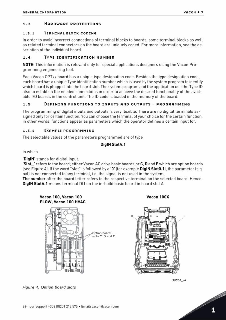
‘DigIN’ stands for digital input.‘Slot_’ refers to the board; either Vacon AC drive basic boards,or C, D and E which are option boards (see Figure 4). If the word “slot” is followed by a ‘0’ (for example DigIN Slot0.1), the parameter (sig-nal) is not connected to any terminal, i.e. the signal is not used in the system.The number after the board letter refers to the respective terminal on the selected board. Hence, DigIN SlotA.1 means terminal DI1 on the in-build basic board in board slot A.
Figure 4. Option board slots
3050A_uk
Option boardslots C, D and E
Vacon 100, Vacon 100 FLOW, Vacon 100 HVAC
Vacon 100X
D E
24-hour support +358 (0)201 212 575 • Email: [email protected]
1
vacon • 8 General information
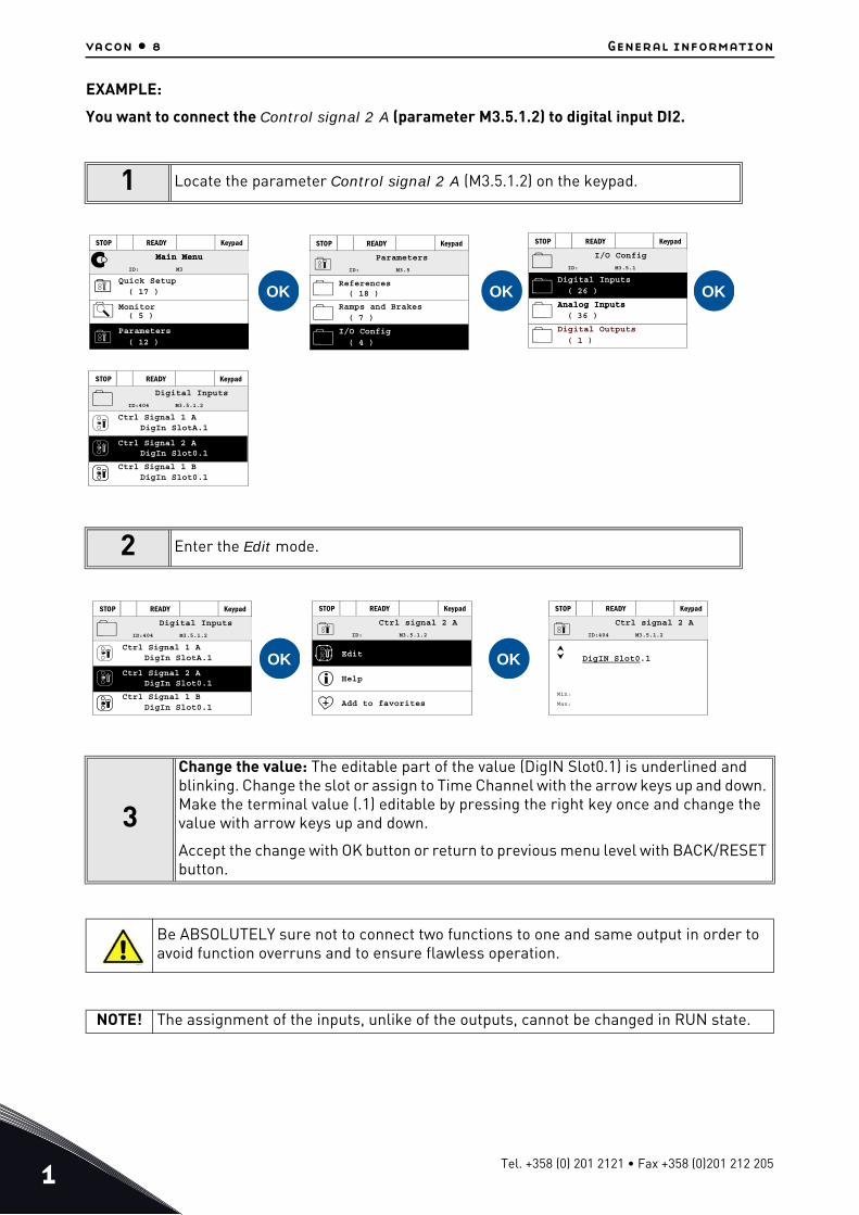
EXAMPLE:
You want to connect the Control signal 2 A (parameter M3.5.1.2) to digital input DI2.
1 Locate the parameter Control signal 2 A (M3.5.1.2) on the keypad.
2 Enter the Edit mode.
3
Change the value: The editable part of the value (DigIN Slot0.1) is underlined and blinking. Change the slot or assign to Time Channel with the arrow keys up and down. Make the terminal value (.1) editable by pressing the right key once and change the value with arrow keys up and down.
Accept the change with OK button or return to previous menu level with BACK/RESET button.
Be ABSOLUTELY sure not to connect two functions to one and same output in order to avoid function overruns and to ensure flawless operation.
NOTE! The assignment of the inputs, unlike of the outputs, cannot be changed in RUN state.
OK OK OK
STOP READY Keypad
Main MenuMain Menu
Quick Setup( 17 )
( 5 )MonitorParameters
( 12 )
ID: M3
STOP READY Keypad
References( 18 )
Parameters
I/O Config
( 4 )
Ramps and Brakes( 7 )
ID: M3.5
STOP READY Keypad
I/O Config
Digital Inputs
( 26 )
Analog Inputs( 36 )
Analog Inputs
Digital Outputs
( 1 )
ID: M3.5.1
STOP READY Keypad
Digital Inputs
Ctrl Signal 1 A
Ctrl Signal 2 ADigIn Slot0.1
DigIn Slot0.1
DigIn SlotA.1
Ctrl Signal 1 B
ID:404 M3.5.1.2
OK OK
STOP READY Keypad
Digital Inputs
Ctrl Signal 1 A
Ctrl Signal 2 ADigIn Slot0.1
DigIn Slot0.1
DigIn SlotA.1
Ctrl Signal 1 B
ID:404 M3.5.1.2
STOP READY Keypad
Ctrl signal 2 A
Edit
Help
Add to favorites
ID: M3.5.1.2
STOP READY Keypad
Ctrl signal 2 A
Min:
Max:
ID:404 M3.5.1.2
DigIN Slot0.1
13006.emf
Tel. +358 (0) 201 2121 • Fax +358 (0)201 212 205
Installation of option boards vacon • 9
2. INSTALLATION OF OPTION BOARDS
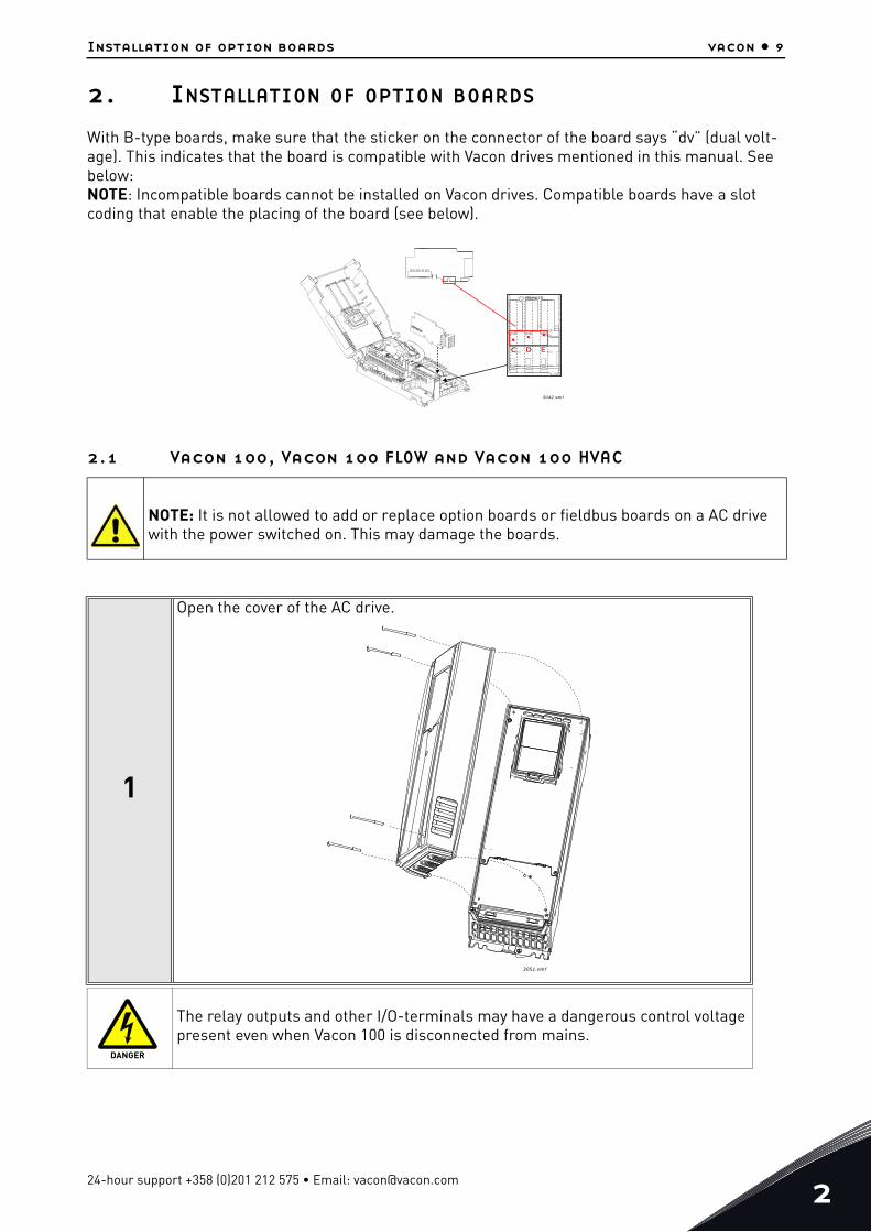
With B-type boards, make sure that the sticker on the connector of the board says “dv” (dual volt-age). This indicates that the board is compatible with Vacon drives mentioned in this manual. See below:NOTE: Incompatible boards cannot be installed on Vacon drives. Compatible boards have a slot coding that enable the placing of the board (see below).
2.1 Vacon 100, Vacon 100 FLOW and Vacon 100 HVAC
NOTE: It is not allowed to add or replace option boards or fieldbus boards on a AC drive with the power switched on. This may damage the boards.
1
Open the cover of the AC drive.
The relay outputs and other I/O-terminals may have a dangerous control voltage present even when Vacon 100 is disconnected from mains.
E
3042.emf
DC
13006.emf
3051.emf
DANGER
24-hour support +358 (0)201 212 575 • Email: [email protected]
2
vacon • 10 Installation of option boards
2
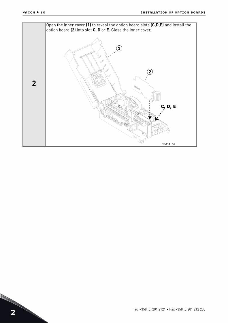
Open the inner cover (1) to reveal the option board slots (C,D,E) and install the option board (2) into slot C, D or E. Close the inner cover.
3043A 00
C, D, E
1
2
Tel. +358 (0) 201 2121 • Fax +358 (0)201 212 205

Installation of option boards vacon • 11
2.2 Vacon 100 X
1
Open the cover of the AC drive.
11638_00
24-hour support +358 (0)201 212 575 • Email: [email protected]
2
vacon • 12 Installation of option boards
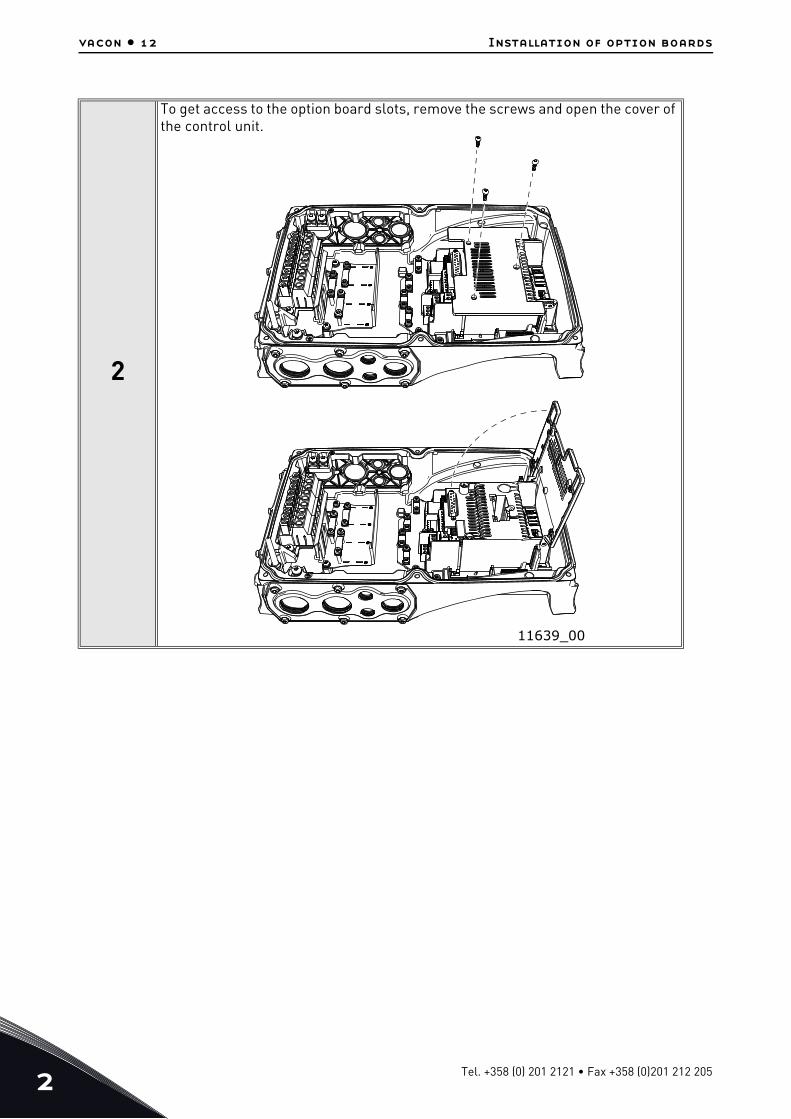
2
To get access to the option board slots, remove the screws and open the cover of the control unit.
11639_00
Tel. +358 (0) 201 2121 • Fax +358 (0)201 212 205

Installation of option boards vacon • 13
3
Install the option board into the correct slot, D or E.
4 Close the option board cover.
5
Remove the cable entry plate if nec-essary, e.g. when using big cable plugs. Choose the proper entry plate (right, left, bottom) depending on the wiring plan. Make sure that the mo-tor cables do not use the same entry plate as signal cabling.
D E
11640_00
11641_00
24-hour support +358 (0)201 212 575 • Email: [email protected]
2
vacon • 14 Installation of option boards
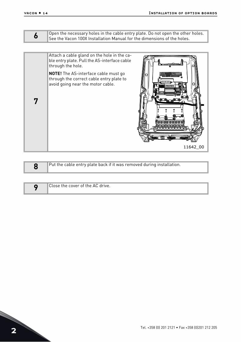
6 Open the necessary holes in the cable entry plate. Do not open the other holes. See the Vacon 100X Installation Manual for the dimensions of the holes.
7
Attach a cable gland on the hole in the ca-ble entry plate. Pull the AS-interface cable through the hole.
NOTE! The AS-interface cable must go through the correct cable entry plate to avoid going near the motor cable.
8 Put the cable entry plate back if it was removed during installation.
9 Close the cover of the AC drive.
11642_00
Tel. +358 (0) 201 2121 • Fax +358 (0)201 212 205
Installation of option boards vacon • 15
2.3 Prepare for use
We recommend to ground the control cables in the manner presented below. Note that the images are suggestive, because the cables can vary.
1
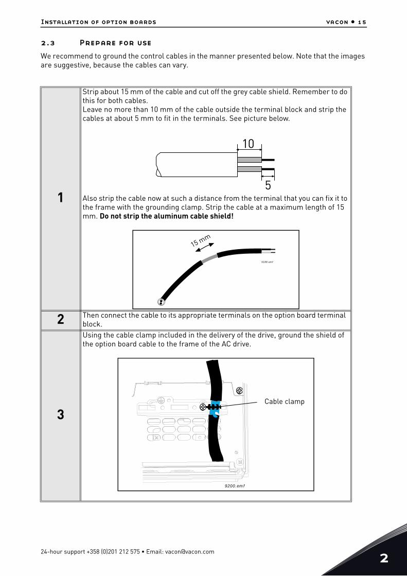
Strip about 15 mm of the cable and cut off the grey cable shield. Remember to do this for both cables.Leave no more than 10 mm of the cable outside the terminal block and strip the cables at about 5 mm to fit in the terminals. See picture below.
Also strip the cable now at such a distance from the terminal that you can fix it to the frame with the grounding clamp. Strip the cable at a maximum length of 15 mm. Do not strip the aluminum cable shield!
2 Then connect the cable to its appropriate terminals on the option board terminal block.
3
Using the cable clamp included in the delivery of the drive, ground the shield of the option board cable to the frame of the AC drive.
10
5
15 mm
9188.emf
9200.emf
Cable clamp
24-hour support +358 (0)201 212 575 • Email: [email protected]
2
vacon • 16 Installation of option boards
4
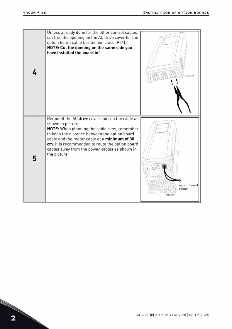
Unless already done for the other control cables, cut free the opening on the AC drive cover for the option board cable (protection class IP21). NOTE: Cut the opening on the same side you have installed the board in!
5
Remount the AC drive cover and run the cable as shown in picture.NOTE: When planning the cable runs, remember to keep the distance between the option board cable and the motor cable at a minimum of 30 cm. It is recommended to route the option board cables away from the power cables as shown in the picture.
9201.emf
option boardcables
7112.emf
Tel. +358 (0) 201 2121 • Fax +358 (0)201 212 205

Installation of option boards vacon • 17
2.4 Control cables
The control cables must be at least 0.5 mm2 screened multicore cables. The maximum terminal wire size is 2.5 mm2 for the relay terminals and other terminals.
Find the tightening torques of the control and relay board terminals in Table below.
4 = Screened cable equipped with compact low-impedance shield (JAMAK, SAB/ÖZCuY-O or similar).
2.5 Board information sticker
Each I/O option board package delivered by the factory includes a sticker (shown below) where pos-sible modifications made in the AC drive are noted. Write the board type, the slot in which it was mounted and the date on the sticker. Finally, attach the sticker on your drive.
Table 2. Control cable tightening torques
Terminal screwTightening torque
Nm lb-in.
All I/O and relay terminals(screw M3) 0.45 4.00
Table 3: Cable types required to meet standards
Cable type
1st environment 2nd environment
EMC levelsAccording to EN61800-3 (2004)
Category C2 Category C3 Level T
Control cable 4 4 4
Product modified
Date:Date:Date:
9004.emf
24-hour support +358 (0)201 212 575 • Email: [email protected]
3
vacon • 18 Description of type ‘B’ and ‘F’ boards
3. DESCRIPTION OF TYPE ‘B’ AND ‘F’ BOARDS
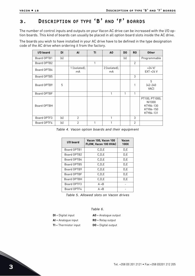
The number of control inputs and outputs on your Vacon AC drive can be increased with the I/O op-tion boards. This kind of boards can usually be placed in all option board slots inside the AC drive.
The boards you wish to have installed in your AC drive have to be defined in the type designation code of the AC drive when ordering it from the factory.
Table 4. Vacon option boards and their equipment
I/O board DI AI TI AO DO RO Other
Board OPTB1 (6) (6) Programmable
Board OPTB2 1 2
Board OPTB41 (isolated);
mA 2 (isolated);
mA +24 V/
EXT +24 V
Board OPTB5 3
Board OPTB9 5 15
(42-240VAC)
Board OPTBF 1 1 1
Board OPTBH
PT100, PT1000,NI1000
KTY84-130KTY84-150KTY84-131
Board OPTF3 (6) 2 1 3
Board OPTF4 (6) 2 1 1 2
I/O board Vacon 100, Vacon 100 FLOW, Vacon 100 HVAC
Vacon 100X
Board OPTB1 C,D,E D,E
Board OPTB2 C,D,E D,E
Board OPTB4 C,D,E D,E
Board OPTB5 C,D,E D,E
Board OPTB9 C,D,E D,E
Board OPTBF C,D,E D,E
Board OPTBH C,D,E D,E
Board OPTF3 A +B -
Board OPTF4 A +B -
Table 5. Allowed slots on Vacon drives
Table 6.
DI = Digital input AO = Analogue output
AI = Analogue input RO = Relay output
TI = Thermistor input DO = Digital output
Tel. +358 (0) 201 2121 • Fax +358 (0)201 212 205
Description of type ‘B’ and ‘F’ boards vacon • 19
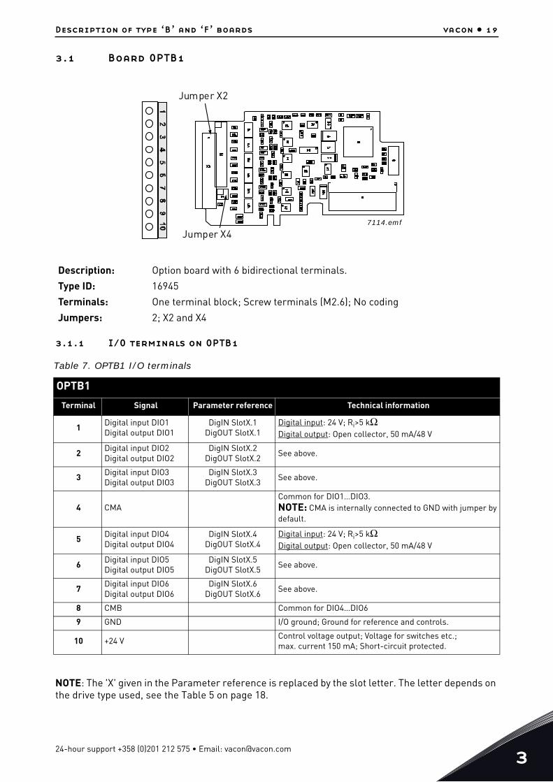
3.1 Board OPTB1
3.1.1 I/O terminals on OPTB1
NOTE: The 'X' given in the Parameter reference is replaced by the slot letter. The letter depends on the drive type used, see the Table 5 on page 18.
Description: Option board with 6 bidirectional terminals.
Type ID: 16945
Terminals: One terminal block; Screw terminals (M2.6); No coding
Jumpers: 2; X2 and X4
Table 7. OPTB1 I/O terminals
OPTB1
Terminal Signal Parameter reference Technical information
1Digital input DIO1Digital output DIO1
DigIN SlotX.1DigOUT SlotX.1
Digital input: 24 V; Ri>5 kΩDigital output: Open collector, 50 mA/48 V
2Digital input DIO2Digital output DIO2
DigIN SlotX.2DigOUT SlotX.2
See above.
3 Digital input DIO3Digital output DIO3
DigIN SlotX.3DigOUT SlotX.3
See above.
4 CMACommon for DIO1…DIO3.NOTE: CMA is internally connected to GND with jumper by default.
5 Digital input DIO4Digital output DIO4
DigIN SlotX.4DigOUT SlotX.4
Digital input: 24 V; Ri>5 kΩDigital output: Open collector, 50 mA/48 V
6Digital input DIO5Digital output DIO5
DigIN SlotX.5DigOUT SlotX.5
See above.
7Digital input DIO6Digital output DIO6
DigIN SlotX.6DigOUT SlotX.6
See above.
8 CMB Common for DIO4…DIO6
9 GND I/O ground; Ground for reference and controls.
10 +24 VControl voltage output; Voltage for switches etc.;max. current 150 mA; Short-circuit protected.
Jumper X2
Jumper X47114.emf
24-hour support +358 (0)201 212 575 • Email: [email protected]
3
vacon • 20 Description of type ‘B’ and ‘F’ boards
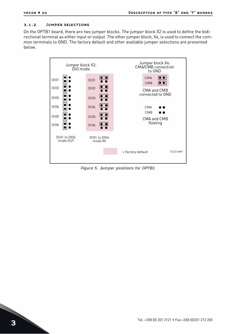
3.1.2 Jumper selections
On the OPTB1 board, there are two jumper blocks. The jumper block X2 is used to define the bidi-rectional terminal as either input or output. The other jumper block, X4, is used to connect the com-mon terminals to GND. The factory default and other available jumper selections are presented below.
Figure 5. Jumper positions for OPTB1
DIO1
DIO2
DIO3
DIO4
DIO5
DIO6
DIO1
DIO2
DIO3
DIO4
DIO5
DIO6
CMA
CMB
CMA
CMB
Jumper block X2:DIO mode
Jumper block X4:CMA/CMB connection
to GND
DIO1 to DIO6mode OUT
DIO1 to DIO6mode IN
= Factory default
CMA and CMBconnected to GND
CMA and CMBfloating
7113.emf
Tel. +358 (0) 201 2121 • Fax +358 (0)201 212 205
Description of type ‘B’ and ‘F’ boards vacon • 21
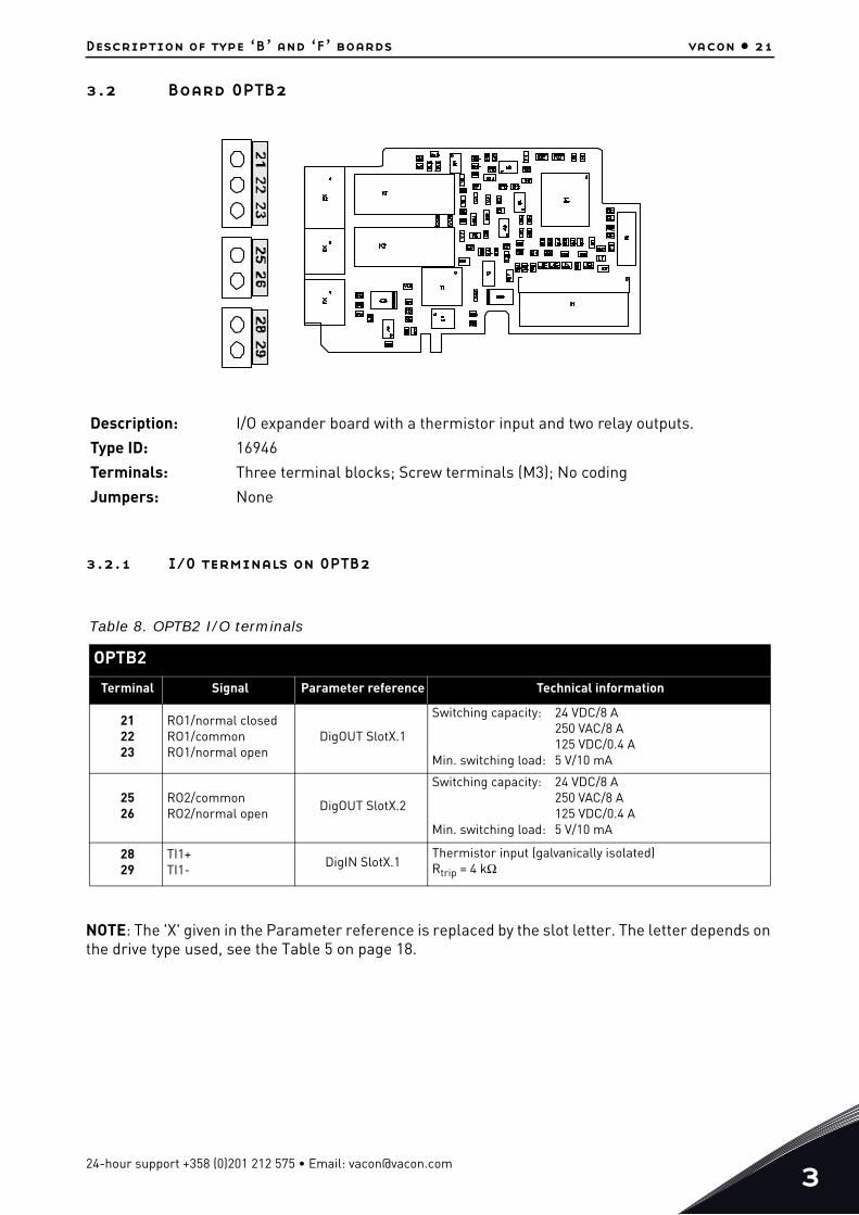
3.2 Board OPTB2
3.2.1 I/O terminals on OPTB2
NOTE: The 'X' given in the Parameter reference is replaced by the slot letter. The letter depends on the drive type used, see the Table 5 on page 18.
Description: I/O expander board with a thermistor input and two relay outputs.
Type ID: 16946
Terminals: Three terminal blocks; Screw terminals (M3); No coding
Jumpers: None
Table 8. OPTB2 I/O terminals
OPTB2
Terminal Signal Parameter reference Technical information
212223
RO1/normal closedRO1/commonRO1/normal open
DigOUT SlotX.1
Switching capacity: 24 VDC/8 A250 VAC/8 A125 VDC/0.4 A
Min. switching load: 5 V/10 mA
2526
RO2/commonRO2/normal open
DigOUT SlotX.2
Switching capacity: 24 VDC/8 A250 VAC/8 A125 VDC/0.4 A
Min. switching load: 5 V/10 mA
2829
TI1+TI1-
DigIN SlotX.1Thermistor input (galvanically isolated)Rtrip = 4 kΩ
24-hour support +358 (0)201 212 575 • Email: [email protected]
3
vacon • 22 Description of type ‘B’ and ‘F’ boards
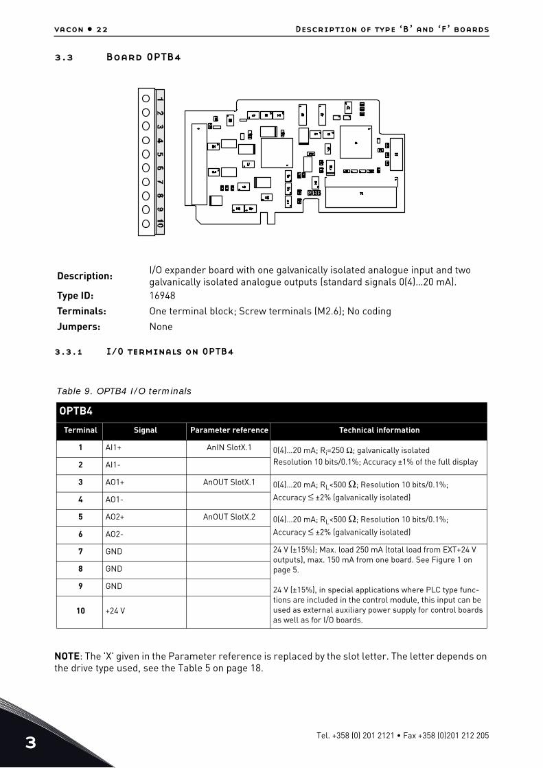
3.3 Board OPTB4
3.3.1 I/O terminals on OPTB4
NOTE: The 'X' given in the Parameter reference is replaced by the slot letter. The letter depends on the drive type used, see the Table 5 on page 18.
Description: I/O expander board with one galvanically isolated analogue input and two galvanically isolated analogue outputs (standard signals 0(4)…20 mA).
Type ID: 16948
Terminals: One terminal block; Screw terminals (M2.6); No coding
Jumpers: None
Table 9. OPTB4 I/O terminals
OPTB4
Terminal Signal Parameter reference Technical information
1 AI1+ AnIN SlotX.1 0(4)…20 mA; Ri=250 Ω; galvanically isolatedResolution 10 bits/0.1%; Accuracy ±1% of the full display2 AI1-
3 AO1+ AnOUT SlotX.1 0(4)…20 mA; RL<500 Ω; Resolution 10 bits/0.1%;
Accuracy ≤ ±2% (galvanically isolated)4 AO1-
5 AO2+ AnOUT SlotX.2 0(4)…20 mA; RL<500 Ω; Resolution 10 bits/0.1%;
Accuracy ≤ ±2% (galvanically isolated)6 AO2-
7 GND 24 V (±15%); Max. load 250 mA (total load from EXT+24 V outputs), max. 150 mA from one board. See Figure 1 on page 5.
24 V (±15%), in special applications where PLC type func-tions are included in the control module, this input can be used as external auxiliary power supply for control boards as well as for I/O boards.
8 GND
9 GND
10 +24 V
Tel. +358 (0) 201 2121 • Fax +358 (0)201 212 205
Description of type ‘B’ and ‘F’ boards vacon • 23
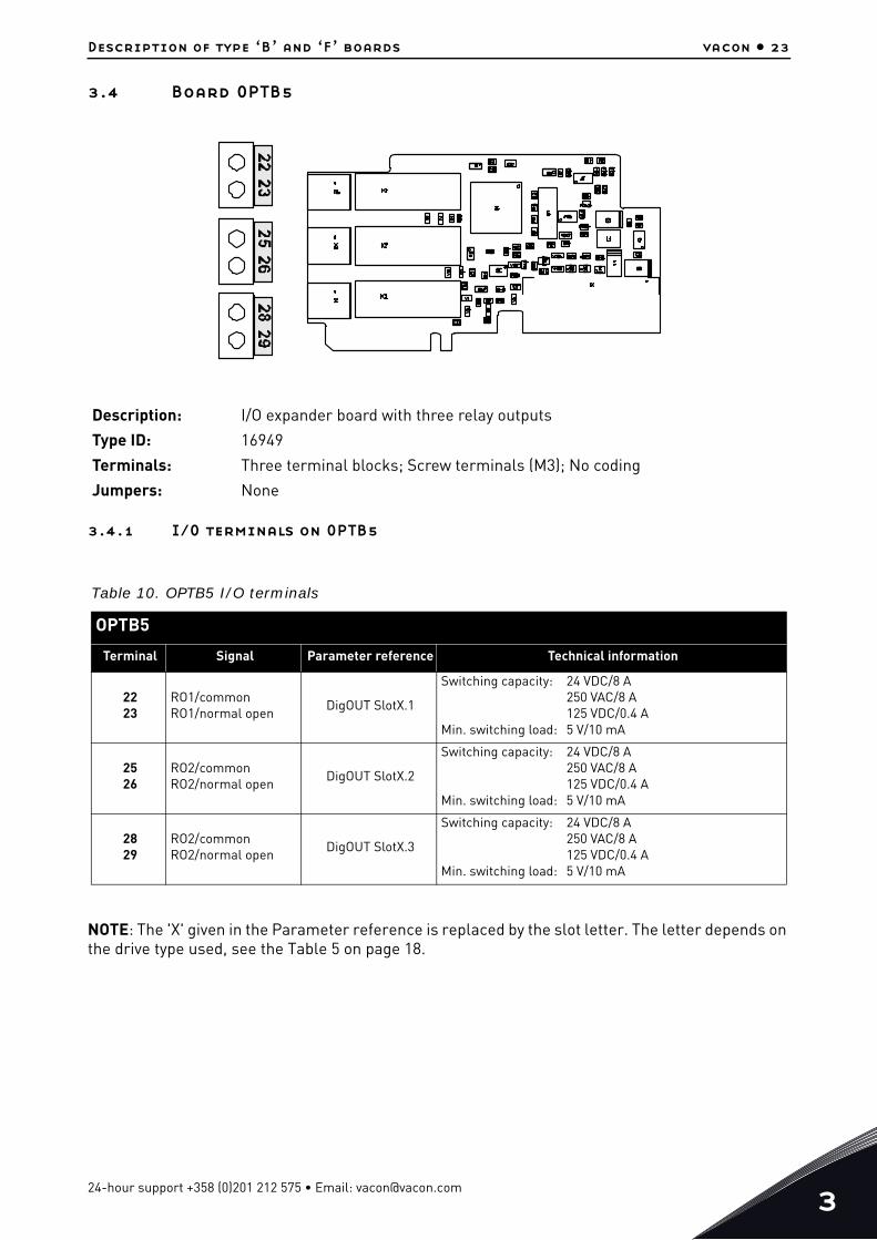
3.4 Board OPTB5
3.4.1 I/O terminals on OPTB5
NOTE: The 'X' given in the Parameter reference is replaced by the slot letter. The letter depends on the drive type used, see the Table 5 on page 18.
Description: I/O expander board with three relay outputs
Type ID: 16949
Terminals: Three terminal blocks; Screw terminals (M3); No coding
Jumpers: None
Table 10. OPTB5 I/O terminals
OPTB5
Terminal Signal Parameter reference Technical information
2223
RO1/commonRO1/normal open
DigOUT SlotX.1
Switching capacity: 24 VDC/8 A250 VAC/8 A125 VDC/0.4 A
Min. switching load: 5 V/10 mA
2526
RO2/commonRO2/normal open
DigOUT SlotX.2
Switching capacity: 24 VDC/8 A250 VAC/8 A125 VDC/0.4 A
Min. switching load: 5 V/10 mA
2829
RO2/commonRO2/normal open
DigOUT SlotX.3
Switching capacity: 24 VDC/8 A250 VAC/8 A125 VDC/0.4 A
Min. switching load: 5 V/10 mA
24-hour support +358 (0)201 212 575 • Email: [email protected]
3
vacon • 24 Description of type ‘B’ and ‘F’ boards
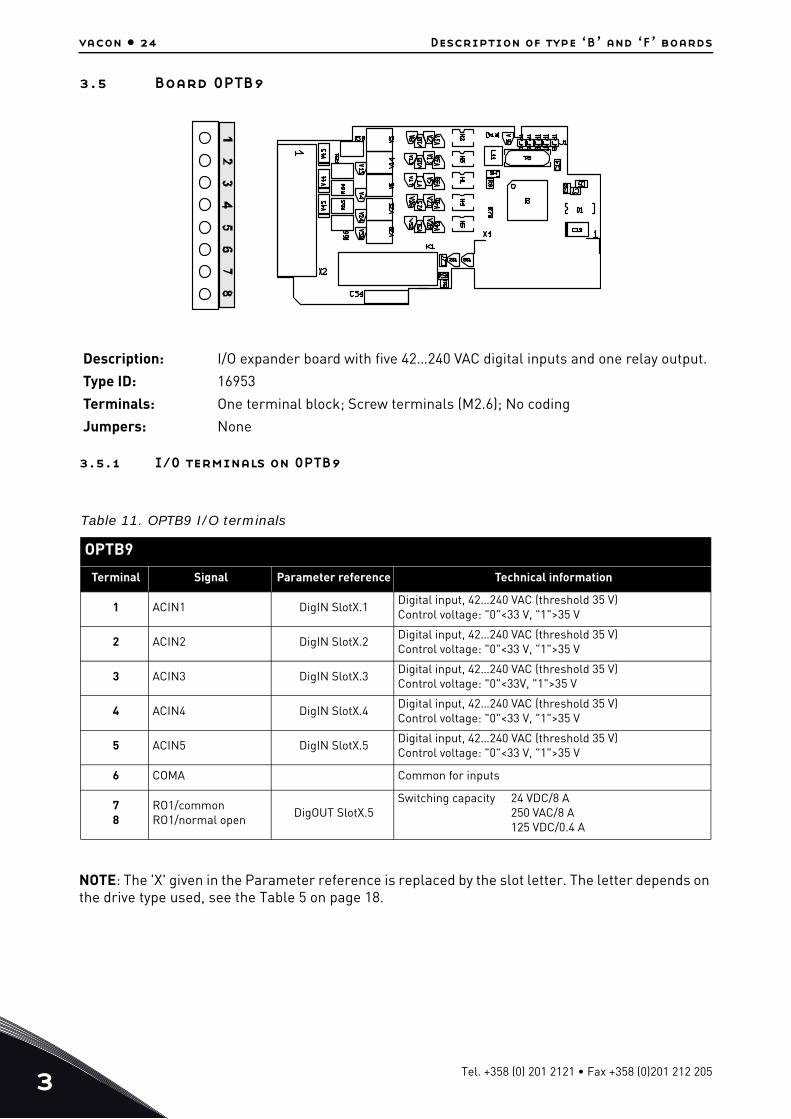
3.5 Board OPTB9
3.5.1 I/O terminals on OPTB9
NOTE: The 'X' given in the Parameter reference is replaced by the slot letter. The letter depends on the drive type used, see the Table 5 on page 18.
Description: I/O expander board with five 42…240 VAC digital inputs and one relay output.
Type ID: 16953
Terminals: One terminal block; Screw terminals (M2.6); No coding
Jumpers: None
Table 11. OPTB9 I/O terminals
OPTB9
Terminal Signal Parameter reference Technical information
1 ACIN1 DigIN SlotX.1Digital input, 42…240 VAC (threshold 35 V)Control voltage: "0"<33 V, "1">35 V
2 ACIN2 DigIN SlotX.2Digital input, 42…240 VAC (threshold 35 V)Control voltage: "0"<33 V, "1">35 V
3 ACIN3 DigIN SlotX.3Digital input, 42…240 VAC (threshold 35 V)Control voltage: "0"<33V, "1">35 V
4 ACIN4 DigIN SlotX.4Digital input, 42…240 VAC (threshold 35 V)Control voltage: "0"<33 V, "1">35 V
5 ACIN5 DigIN SlotX.5Digital input, 42…240 VAC (threshold 35 V)Control voltage: "0"<33 V, "1">35 V
6 COMA Common for inputs
78
RO1/commonRO1/normal open
DigOUT SlotX.5Switching capacity 24 VDC/8 A
250 VAC/8 A125 VDC/0.4 A
Tel. +358 (0) 201 2121 • Fax +358 (0)201 212 205
Description of type ‘B’ and ‘F’ boards vacon • 25
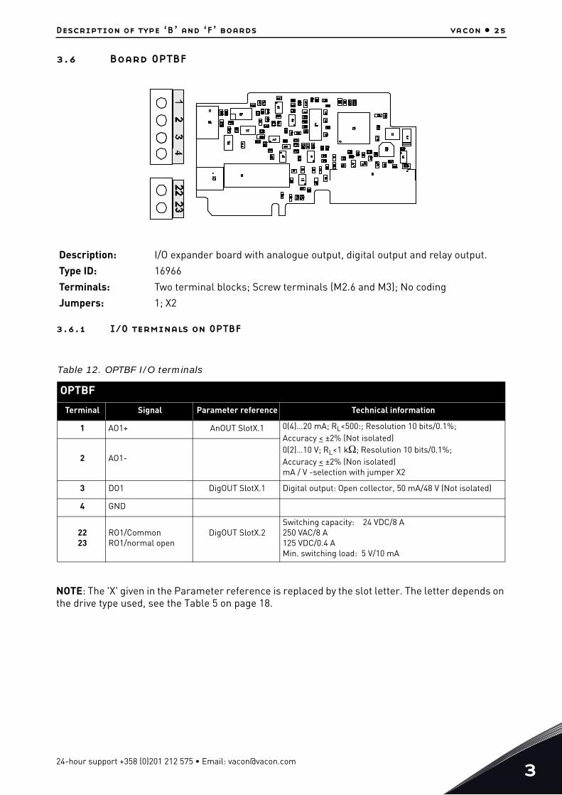
3.6 Board OPTBF
3.6.1 I/O terminals on OPTBF
NOTE: The 'X' given in the Parameter reference is replaced by the slot letter. The letter depends on the drive type used, see the Table 5 on page 18.
Description: I/O expander board with analogue output, digital output and relay output.
Type ID: 16966
Terminals: Two terminal blocks; Screw terminals (M2.6 and M3); No coding
Jumpers: 1; X2
Table 12. OPTBF I/O terminals
OPTBF
Terminal Signal Parameter reference Technical information
1 AO1+ AnOUT SlotX.1 0(4)…20 mA; RL<500:; Resolution 10 bits/0.1%;Accuracy < ±2% (Not isolated)0(2)…10 V; RL<1 kΩ; Resolution 10 bits/0.1%;Accuracy < ±2% (Non isolated)mA / V -selection with jumper X2
2 AO1-
3 DO1 DigOUT SlotX.1 Digital output: Open collector, 50 mA/48 V (Not isolated)
4 GND
2223
RO1/CommonRO1/normal open
DigOUT SlotX.2Switching capacity: 24 VDC/8 A250 VAC/8 A125 VDC/0.4 AMin. switching load: 5 V/10 mA
24-hour support +358 (0)201 212 575 • Email: [email protected]
3
vacon • 26 Description of type ‘B’ and ‘F’ boards
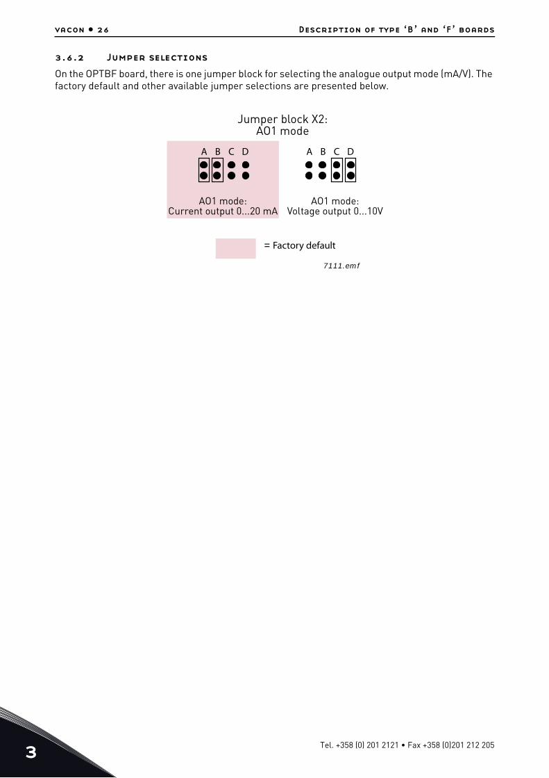
3.6.2 Jumper selections
On the OPTBF board, there is one jumper block for selecting the analogue output mode (mA/V). The factory default and other available jumper selections are presented below.
A B C D A B C D
Jumper block X2:AO1 mode
AO1 mode:Current output 0...20 mA
AO1 mode:Voltage output 0...10V
= Factory default
7111.emf
Tel. +358 (0) 201 2121 • Fax +358 (0)201 212 205
Description of type ‘B’ and ‘F’ boards vacon • 27
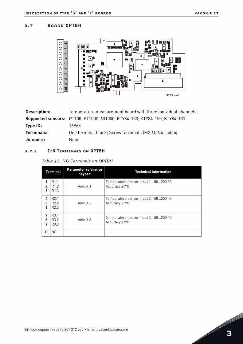
3.7 Board OPTBH
3.7.1 I/O Terminals on OPTBH
Description: Temperature measurement board with three individual channels.
Supported sensors: PT100, PT1000, NI1000, KTY84-130, KTY84-150, KTY84-131
Type ID: 16968
Terminals: One terminal block; Screw terminals (M2.6); No coding
Jumpers: None
Table 13. I/O Terminals on OPTBH
TerminalParameter reference
KeypadTechnical information
123
R1.1R1.2R1.3
AnIn:X.1Temperature sensor input 1, -50...200 °CAccuracy ±1°C
456
R2.1R2.2R2.3
AnIn:X.2Temperature sensor input 2, -50...200 °CAccuracy ±1°C
789
R3.1R3.2R3.3
AnIn:X.3Temperature sensor input 3, -50...200 °CAccuracy ±1°C
10 NC
3025.emf
12
34
56
78
910
24-hour support +358 (0)201 212 575 • Email: [email protected]
3
vacon • 28 Description of type ‘B’ and ‘F’ boards
3.7.2 OPTBH accuracy
The following tables represent the results of accuracy measurements in laboratory environment. In the tests, Draga JAMAK cable was used. Testing covered different sensor setups and sensor type combinations.
Table 14. PT100 accuracy
Cable length (m) 3-wire 2-wire Accuracy (°C)<=300 x -1 < x < 3
50 x -1 < x < 14
Table 15. PT1000, KTY84 and Ni1000 (Ni1000 DIN) accuracy
Cable length (m) 3-wire 2-wire Accuracy (°C)<=300 x -1 < x < 1
150 x -1 < x < 5
50 x -1 < x < 3
Tel. +358 (0) 201 2121 • Fax +358 (0)201 212 205

Description of type ‘B’ and ‘F’ boards vacon • 29
3.7.3 OPTBH option board wiring scheme:
Use shielded cables and connect the cable shield to grounding clamp in the drive. Allowed sensor configurations are shown in the figures below:
Two-wire configuration Three-wire configuration
Two-wire configuration Three-wire configuration
3.7.4 OPTBH board parameters
NOTE! The correct sensor for the correct channel must be selected. Always configure unused chan-nels to 0 = No sensor
Code Parameter Min Max Unit Default ID Description
7.x.1.1 Sensor 1 type 0 6 0
0 = No Sensor1 = PT1002 = PT10003 = Ni10004 = KTY845 = 2 x PT1006 = 3 x PT100
7.x.1.2 Sensor 2 type 0 6 0 See above
7.x.1.3 Sensor 3 type 0 6 0 See above
24-hour support +358 (0)201 212 575 • Email: [email protected]
3
vacon • 30 Description of type ‘B’ and ‘F’ boards
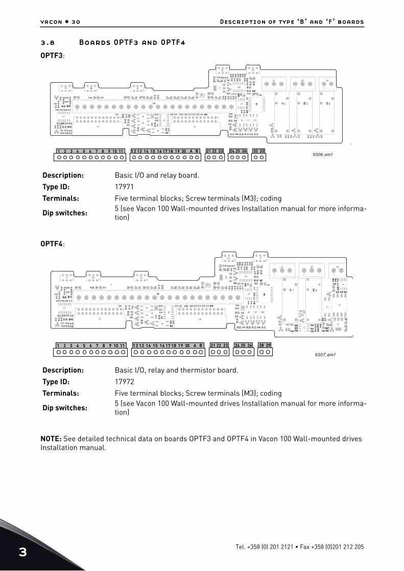
3.8 Boards OPTF3 and OPTF4
OPTF3:
OPTF4:
NOTE: See detailed technical data on boards OPTF3 and OPTF4 in Vacon 100 Wall-mounted drives Installation manual.
Description: Basic I/O and relay board.
Type ID: 17971
Terminals: Five terminal blocks; Screw terminals (M3); coding
Dip switches: 5 (see Vacon 100 Wall-mounted drives Installation manual for more informa-tion)
Description: Basic I/O, relay and thermistor board.
Type ID: 17972
Terminals: Five terminal blocks; Screw terminals (M3); coding
Dip switches: 5 (see Vacon 100 Wall-mounted drives Installation manual for more informa-tion)
9306.emf1 2 3 4 5 6 7 8 9 10 11 1 2 13 14 15 16 17 18 19 30 21 22 23 24 25 26 32 33A B
9307.emf
1 2 3 4 5 6 7 8 9 10 11 1 2 13 14 15 16 17 18 19 30 21 22 23 24 25 26 28 29A B
Tel. +358 (0) 201 2121 • Fax +358 (0)201 212 205
Description of type ‘B’ and ‘F’ boards vacon • 31
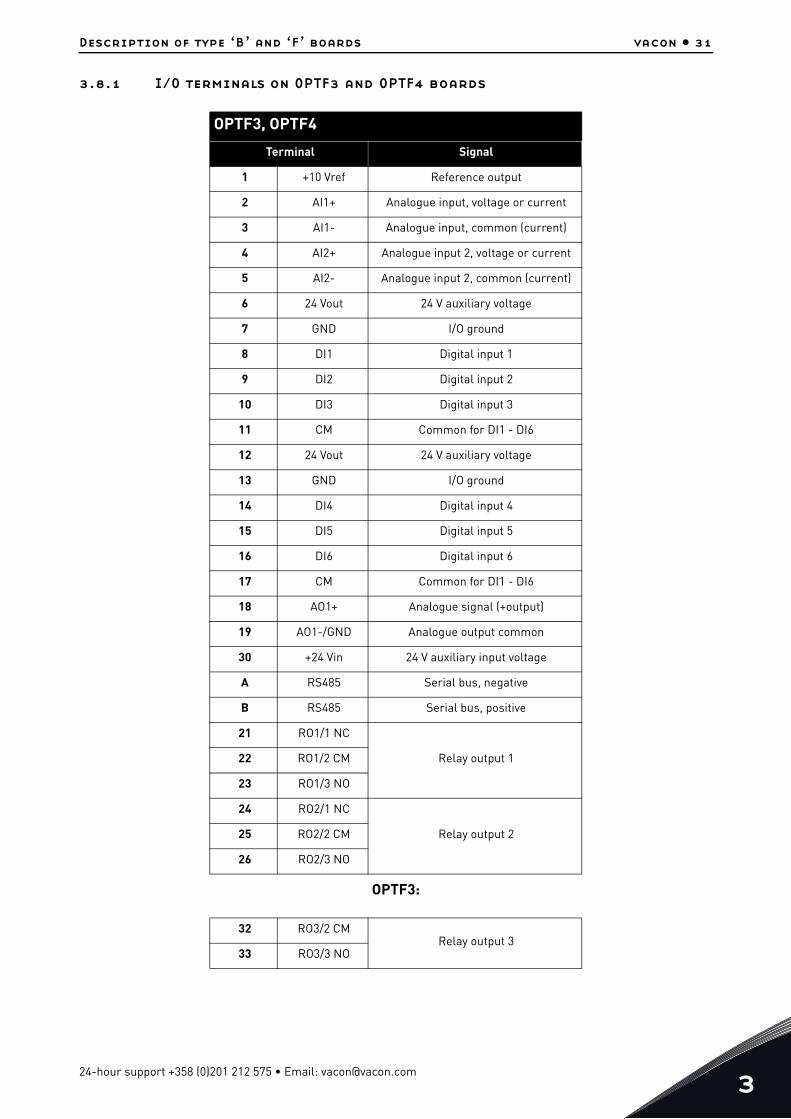
3.8.1 I/O terminals on OPTF3 and OPTF4 boards
OPTF3:
OPTF3, OPTF4
Terminal Signal
1 +10 Vref Reference output
2 AI1+ Analogue input, voltage or current
3 AI1- Analogue input, common (current)
4 AI2+ Analogue input 2, voltage or current
5 AI2- Analogue input 2, common (current)
6 24 Vout 24 V auxiliary voltage
7 GND I/O ground
8 DI1 Digital input 1
9 DI2 Digital input 2
10 DI3 Digital input 3
11 CM Common for DI1 - DI6
12 24 Vout 24 V auxiliary voltage
13 GND I/O ground
14 DI4 Digital input 4
15 DI5 Digital input 5
16 DI6 Digital input 6
17 CM Common for DI1 - DI6
18 AO1+ Analogue signal (+output)
19 AO1-/GND Analogue output common
30 +24 Vin 24 V auxiliary input voltage
A RS485 Serial bus, negative
B RS485 Serial bus, positive
21 RO1/1 NC
Relay output 122 RO1/2 CM
23 RO1/3 NO
24 RO2/1 NC
Relay output 225 RO2/2 CM
26 RO2/3 NO
32 RO3/2 CMRelay output 3
33 RO3/3 NO
24-hour support +358 (0)201 212 575 • Email: [email protected]
3
vacon • 32 Description of type ‘B’ and ‘F’ boards
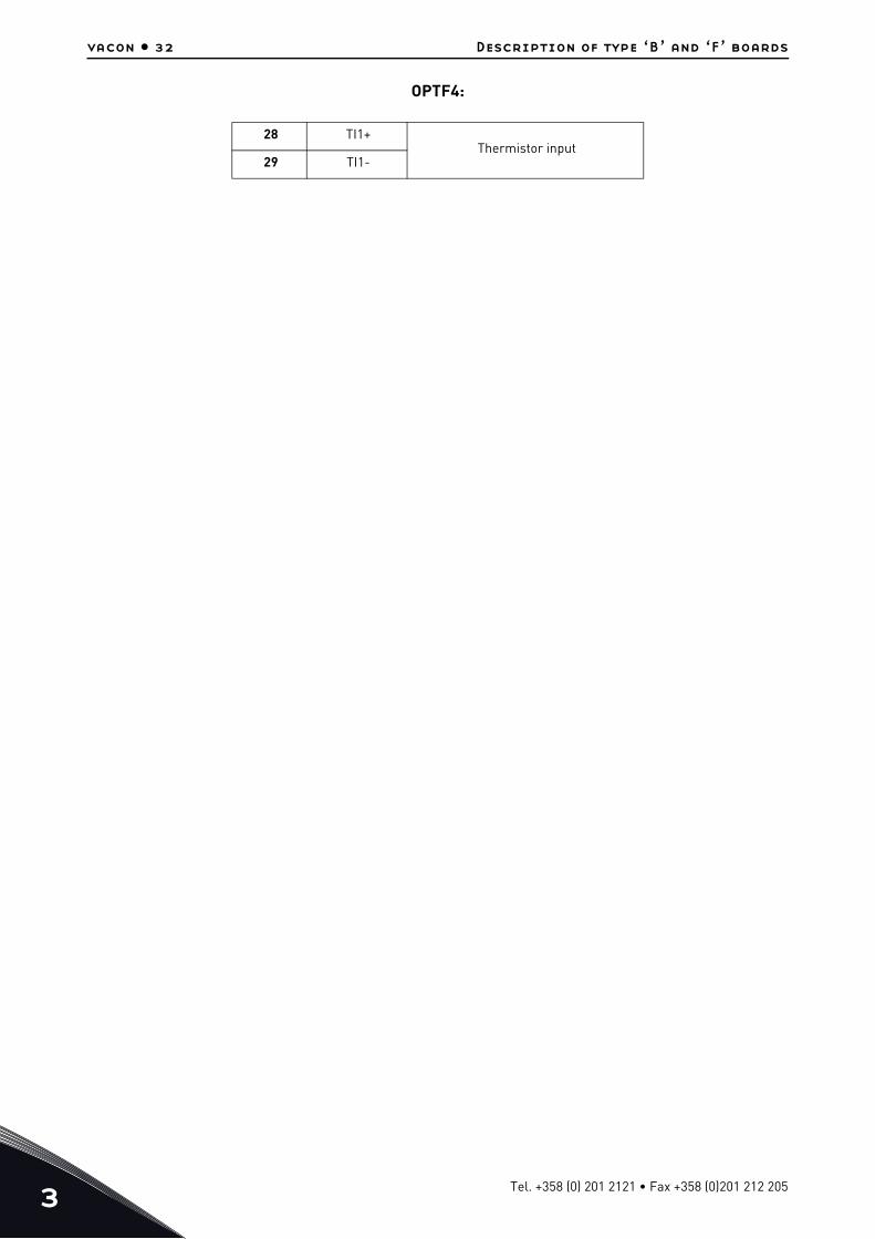
OPTF4:
28 TI1+Thermistor input
29 TI1-
Tel. +358 (0) 201 2121 • Fax +358 (0)201 212 205

Document ID:
Rev. C
Sales code: DOC-OPTBx/Fx+DLUK
Vacon LtdMember of the Danfoss GroupRunsorintie 765380 VaasaFinland
www.danfoss.com