V5000 Integrated Management Utility - Manual · PDF fileCommand line interface ... 2.5.12. sdr...
68
V5000 Integrated Management Utility Version 1.1 Manual T-Platforms 2015
Transcript of V5000 Integrated Management Utility - Manual · PDF fileCommand line interface ... 2.5.12. sdr...

V5000 Integrated Management Utility
Version 1.1
Manual
T-Platforms2015

2
Table of ContentsPreface .................................................................................................................................... 6
1. Document conventions ................................................................................................................ 6
Chapter 1. Web interface ..................................................................................................... 71.1. Supported browsers ................................................................................................................. 71.2. Connection and login ............................................................................................................... 71.3. Overview ................................................................................................................................ 71.4. Information ............................................................................................................................. 9
1.4.1. Information : Chassis .................................................................................................... 91.4.2. “Information : Nodes” ................................................................................................. 12
1.5. “Configuration” ..................................................................................................................... 151.5.1. “Configuration : Chassis” ............................................................................................ 161.5.2. “Configuration : Networks” ......................................................................................... 201.5.3. “Configuration : Access” ............................................................................................. 23
1.6. “Power” ................................................................................................................................ 241.6.1. “Power : Chassis” ....................................................................................................... 241.6.2. “Power : Nodes” ......................................................................................................... 26
1.7. “Chassis Health” .................................................................................................................... 271.7.1. “Chassis Health : Chassis” .......................................................................................... 281.7.2. “Chassis Health : Nodes” ............................................................................................ 291.7.3. “Chassis Health : Fans” ............................................................................................... 301.7.4. “Chassis Health : Alarms and Events” .......................................................................... 31
1.8. “Backup” ............................................................................................................................... 331.9. “Update” ............................................................................................................................... 341.10. “Help” ................................................................................................................................. 35
Chapter 2. Command line interface ................................................................................. 362.1. Command overview ............................................................................................................... 362.2. help command ....................................................................................................................... 362.3. alarms command .................................................................................................................... 362.4. backup command ................................................................................................................... 372.5. chassis command ................................................................................................................... 38
2.5.1. identity subcommand ................................................................................................... 382.5.2. info subcommand ........................................................................................................ 392.5.3. fru subcommand ......................................................................................................... 402.5.4. fwinfo subcommand .................................................................................................... 402.5.5. mc subcommand ......................................................................................................... 402.5.6. id subcommand ........................................................................................................... 412.5.7. time subcommand ....................................................................................................... 41

3
2.5.8. net subcommand ......................................................................................................... 422.5.9. bmc subcommand ....................................................................................................... 482.5.10. psu subcommand ....................................................................................................... 502.5.11. power subcommand ................................................................................................... 512.5.12. sdr subcommand ....................................................................................................... 52
2.6. date command ....................................................................................................................... 522.7. events command .................................................................................................................... 532.8. fans command ....................................................................................................................... 552.9. node command ...................................................................................................................... 56
2.9.1. The list subcommand .................................................................................................. 572.9.2. The info subcommand ................................................................................................. 572.9.3. The fru subcommand .................................................................................................. 572.9.4. The mc info subcommand ........................................................................................... 582.9.5. The bmc subcommand ................................................................................................ 582.9.6. The mac subcommand ................................................................................................. 592.9.7. The power subcommand .............................................................................................. 592.9.8. The sdr subcommand .................................................................................................. 61
2.10. passwd command ................................................................................................................. 622.11. quit command ...................................................................................................................... 632.12. syslog command .................................................................................................................. 632.13. update command .................................................................................................................. 64
Appendix A. Manufacturer information .......................................................................... 65
Appendix B. Change log .................................................................................................... 66
Appendix C. Notes for DHCP server configuration ........................................................ 67

4
List of Figures1. Main page of the web interface ............................................................................... 82. “Information : Chassis : Management S/W” page ................................................. 113. “Information : Chassis : FRU” page ..................................................................... 124. “Information : Nodes : Node X : Summary” page ................................................ 135. “Information : Nodes : Node X : Management S/W” page ................................... 146. “Information : Nodes : Node X : FRU” page ........................................................ 157. “Configuration” page ............................................................................................. 168. “Configuration : Chassis : Identification” page .................................................... 179. “Configuration : Chassis : Date/Time Settings” page ........................................... 1810. “Configuration : Chassis : Power Settings” page ............................................... 1911. “Configuration : Chassis : Syslog Settings” page ................................................ 2012. “Configuration : Networks : SMC Interface” page .............................................. 2113. “Configuration : Networks : BMC Subnet” page ................................................ 2314. “Configuration : Access : Password Settings” page ............................................ 2415. “Power : Chassis : Power Summary” page ......................................................... 2516. “Power : Chassis : Chassis Power” page ............................................................. 2617. “Power : Nodes : Node X : Node Power” page .................................................. 2718. “Chassis Health : Chassis Sensors” page ............................................................ 2919. “Chassis Health : Nodes : Node X : Node Sensors” page ................................... 3020. Chassis CFM monitoring and management interface .......................................... 3121. System event log view ......................................................................................... 3222. System alarm list view ........................................................................................ 3323. SMC firmware settings backup creation interface ............................................... 3424. SMC firmware settings backup restoration interface ........................................... 3425. SMC firmware update interface ........................................................................... 3526. Help panel ............................................................................................................ 35

5
List of Tables1. States of the compute nodes .................................................................................. 102. Denotations for IP addresses of the compute nodes .............................................. 103. Change log ............................................................................................................. 66

6
PrefaceThis manual describes the integrated management utility (IMU) of the modular V-
Class server system by T-Platforms. The management utility is used to configure andmonitor the V-Class system.
This document is created for administrators that perform the configuration andmaintenance of the system. If any problems are encountered, request the technicalsupport from T-Platforms. The contact information is provided in Appendix A.
1. Document conventionsThe following notation is used in the document:
● The syntax of a CLI command is given in Courier New bold.
● Elements in triangular brackets (< >) indicate the field required as input along with acommand, for example <integer (100-1000)>.
7
Chapter 1. Web interfaceThis chapter describes the IMU web interface and explains main concepts related
to it.Web interface (WI) of the integrated management utility (IMU) provides realtime
information and control over the chassis and available nodes. The WI is designed forsystem administrators. The information is represented mostly in tables and lists.
1.1. Supported browsersThe following browsers have been tested for use with the IMU web interface. It is
recommended that you use the most current revision of the browser you choose. Theminimum browser revisions supported by the IMU web interface are shown below:
● Mozilla Firefox 11;
● Google Chrome 18;
● Safari 5;
● Opera 11.6.
1.2. Connection and loginTo log into the IMU:
1. Launch a web browser.
2. Use the browser to access the Chassis Management Module by its IP address, e.g.http://10.10.10.10 (default address).
3. When the browser makes contact with the Chassis Management Module, enter yourusername and password, then click «LOGIN». The default username is admin, thedefault password is admin.
4. The IMU main page will then display as shown in fig. 1.
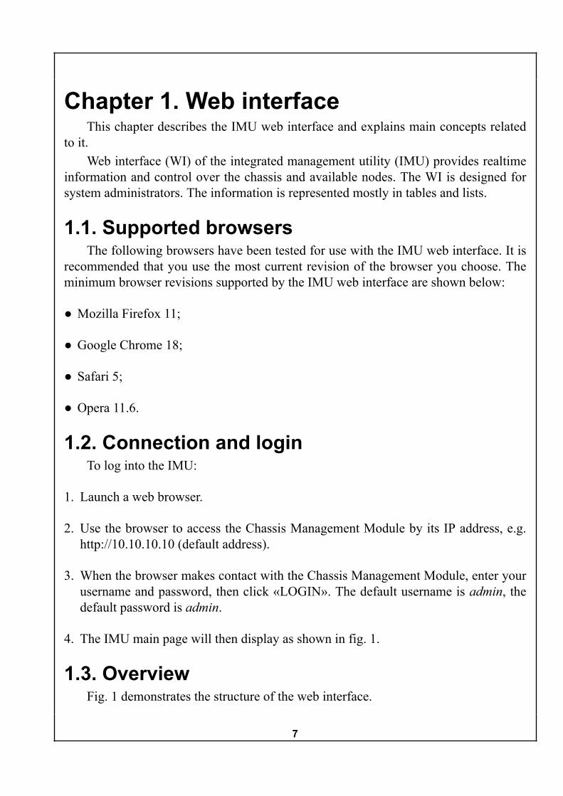
1.3. OverviewFig. 1 demonstrates the structure of the web interface.
8
Figure 1. Main page of the web interface
There are three panels available in the WI: the top panel, the left panel and the centralpanel. The top panel contains the main menu, the left panel provides related side menuitems, and the central panel displays the essential information of the chosen kind.
Also, the bottom of the screen hosts the status panel that displays system time of themanagement module and IMU version. The system time is shown in the local browsertimezone, which is also displayed near the system time.
The main menu provides selection for category of information to be displayed ortype of action to be taken. It includes the following buttons:
● Information
● Configuration
● Power

9
● Health
● Backup
● Update
● Help
There are two actions always shown in the side menu: “Refresh Page” and “Logout”.The “Refresh Page” action updates the information on the screen, and “Logout” actionimmediately logs the user out of the Web interface. Please not that the “Logout" buttonmight incorrectly work in certain browsers due to the used authentication method. It isrecommended to close your browser to complete the logout process. If the browser-pro-vided “remember password” option was used during the login, the information aboutIMU login and password has to be deleted from the browser settings in order to maintainthe access security.
Each menu item is described in greater detail in the following sections.
1.4. InformationThe “Information” section displays general information about chassis and available
nodes.
1.4.1. Information : ChassisThe “Chassis” subsection enables output for general information about the system
chassis. When clicked, it reveals the list of three pages:
● Summary
● Management S/W
● FRU
These pages are described in the following sections.
1.4.1.1. “Information : Chassis : Summary”Clicking on this page makes the central panel display the rear view of the chassis,
available nodes and power supply units. This view is shown by default when a user logsin the IMU web interface. A “Chassis summary information” table with brief informationis located under the image. Each row in the table corresponds to a compute node. Thetable describes the following parameters of the nodes:

10
● “Position” — shows the slots occupied by the node. Slots are numerated from right toleft when viewed from the backside of the chassis.
● “Node Type” — gives the index of the node and type of compute resources it includesin “X[+ GPU]” format, where X stands for CPU type, and optional [+ GPU] part isshown when the node is capable of hosting a GPU.
● “Current State” — shows the state of the node. Available states are:
Table 1. States of the compute nodes
State Description“Detected” Node physical presence in the slot is de-
tected, hardware examination in progress.“Examined” Hardware examination is complete, basic
node information is shown.“Setting” SMC performs IP configuration of the
node.“Ready” The node is configured and ready to work.
● “BMC IP Address” — shows the IP address that BMC of the node is configured touse. The letter near the address means the following:
Table 2. Denotations for IP addresses of the compute nodes
State Description“S” Static IP configuration for node BMC by
chassis SMC.“D” IP configuration by SMC DHCP server.“P” Passive IP configuration, SMC reads IP
settings from the node BMC. In this andprevious (“D”) configuration node BMCmust be in the same subnet as the chas-sis SMC module for all IMU functions towork properly.
“N” No BMC on the node.
● «BMC Netmask» — shows the netmask that BMC of the node is configured to use.

11
● “BMC Default Gateway” — shows the default gateway that BMC of the node is con-figured to use.
Right under the chassis summary table is located a small “Identification” sectionwith the button and status message related to the chassis identification LED located onthe chassis front panel. The ID LED is used for physical distinction of the chassis amongsimilar equipment. The button switches the ID LED on and off, and the status messageshows the current status of the ID LED.
A typical view of this page is shown in fig. 1.
1.4.1.2. “Information : Chassis : Management S/W”This page shows the general information about chassis system management con-
troller firmware on the central panel. The provided information includes SMC firmwareversion, image name, build date. The firmware version for power distribution board(PDB) is also provided in the screen.
A typical view of this page is shown in fig. 2.
Figure 2. “Information : Chassis : Management S/W” page
1.4.1.3. Chassis — FRUThis page shows the version and production date of the chassis hardware compo-
nents.A typical view of this page is shown in fig. 3.

12
Figure 3. “Information : Chassis : FRU” page
1.4.2. “Information : Nodes”The “Nodes” section includes variable number of intermediate subsections that de-
pend on the nodes currently installed in the chassis. Such intermediate subsections willbe further referenced as “Node X” where “X” is the node number. The nodes are num-bered by the number of the slot they occupy. For nodes with double width, the biggernumber is used. Each node subsection includes three pages similar to the chassis: “Sum-mary”, “Management S/W” and “FRU”.
1.4.2.1. “Information : Nodes : Node X : Summary”This page makes the central panel show the table with information about position,
type, state and network configuration of the compute node.A typical view of this page is shown in fig. 4.

13
Figure 4. “Information : Nodes : Node X : Summary” page
1.4.2.2. “Information : Nodes : Node X : Management S/W”This page shows the general information about node BMC firmware.A typical view of this page is shown in fig. 5.

14
Figure 5. “Information : Nodes : Node X : Management S/W” page
1.4.2.3. “Information : Nodes : Node X : FRU”This page shows the hardware design and manufacturing information for node BMC.A typical view of this page is shown in fig. 6.

15
Figure 6. “Information : Nodes : Node X : FRU” page
1.5. “Configuration”The “Configuration” section is used for tuning the general chassis settings. It in-
cludes three subsections:
● “Chassis” — general chassis configuration;
● “Networks” — network settings for chassis SMC and node BMC;
● “Access” — the access management.
When “Configuration” section is selected the chassis settings summary is shown inthe central panel. A typical view of this summary is shown on fig. 7.

16
Figure 7. “Configuration” page
1.5.1. “Configuration : Chassis”
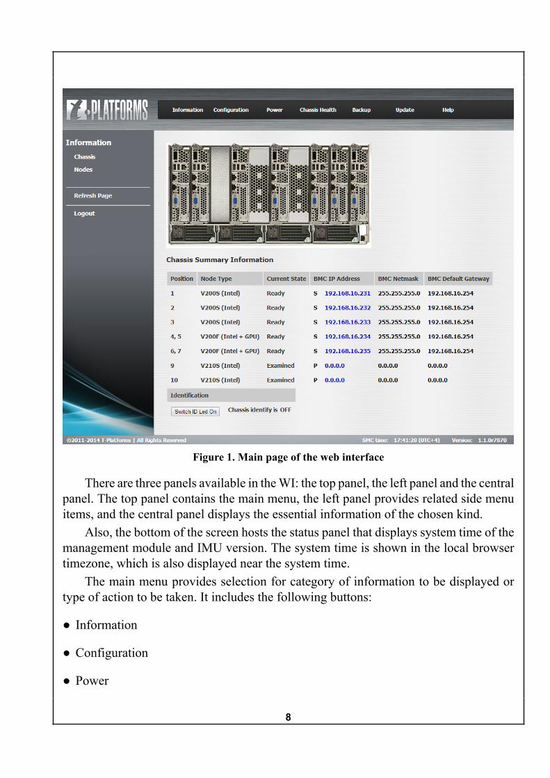
1.5.1.1. “Configuration : Chassis : Identification”This page is used for configuring the chassis identification by the number, address
or ID LED.The “Chassis Number” field accepts the numerical chassis ID. The “SMC Host
Name” and “SMC Domain Name” fields are used to set the respective parameters. These
17
parameters are shown in the web interface and in the system logs on the external syslogserver (see section 1.5.1.4). Click on the “Save Settings” button to save the changes.
When the “Switch ID Led On/Off” button is pressed, the nearby message aboutcurrent state of the ID LED is updated. In the “On” mode the green chassis ID LED isblinking. The ID LED is located on the front panel of the chassis. Chassis identificationcan also be toggled from the «Information : Chassis : Summary” page (see sect. 1.4.1.1)
A typical view of this page is shown in fig. 8.
Figure 8. “Configuration : Chassis : Identification” page
1.5.1.2. “Configuration : Chassis : Date/Time Settings”This page is used to set the system date and time. The synchronization with an ex-
ternal time server can also be configured.The key control on the page is the “Time Source” radiobutton, all other control
elements on this page depend on its state. If the “Built-in Real Time Clock” option isactive, the system date will be taken from the RTC clock installed in SMC, and the“Date” and “SMC Time” fields are enabled. Day, month and year can be selected fromthe respective lists. Time should be input in format hh:mm:ss.
If the “Time Source” radiobutton is configured for the “External NTP Server” op-tion, the “Date” and “SMC Time” fields are deactivated, and “NTP Server” field is en-abled. The address of external NTP server should be provided in this field.
There are three buttons on the page. “Update” button functions in the similar wayto the “Refresh Page” link in the left panel but updates only the time and date from

18
the SMC. “Browser Sync” button sets the time according to client browser time. “SaveSettings” button saves the changes to SMC.
A typical view of this page is shown in fig. 9.
Figure 9. “Configuration : Chassis : Date/Time Settings” page
1.5.1.3. “Configuration : Chassis : Power Settings”This page contains only one checkbox that is used to enable or disable the power
redundancy policy. If enabled, the N+1 redundancy improves the failover capability ofthe system but limits the power budget with the combined power output of the availableN PSUs. The power budget is considered by SMC when it makes the decision to supplythe main power to the newly installed compute modules. When the type of the computemodule is discovered, information about its peak power consumption is received. SMCsubtracts this value from available power budget and supplies main power to the computemodule only if the remaining power budget is greater than 0. Click on the “Save Settings”button to save the changes.
A typical view of this page is shown in fig. 10.

19
Figure 10. “Configuration : Chassis : Power Settings” page
1.5.1.4. “Configuration : Chassis : Syslog Settings”This page includes two controls: the “External Syslog” switch and the “Server” text
field. The switch enables or disables sending system log messages to an external syslogserver, while the text field is used to set the IP address of the server.
NoteThe messages sent to the external syslog server are not the events or alarms
listed on “Chassis Health : Alarms” and “Chassis Health : Events” pages. Thesent messages describe the web interface and ssh access statistics, logs of serv-er-side scripts launched by web interface etc.
View of this page is shown in fig. 11.

20
Figure 11. “Configuration : Chassis : Syslog Settings” page
1.5.2. “Configuration : Networks”
1.5.2.1. “Configuration : Networks : SMC Interface”This page is used for SMC network configuration.The “Address Source” switch allows either static or dynamic (“DHCP”) address
assignment.If static address assignment is selected, a set of text fields becomes available. These
fields are used to input the IP address, netmask, default gateway address, main and back-up DNS servers addresses.
When DHCP mode is selected, all network settings of the chassis are configured bythe DHCP server.
Additional notes on DHCP server configuration are listed in C.The changes should be saved with the “Save Settings” button located below the text
fields.View of this page is shown in fig. 12.

21
Figure 12. “Configuration : Networks : SMC Interface” page
1.5.2.2. «Configuration : Networks : BMC Subnet»This page is used for configuring the network settings for the BMC controllers of
the compute nodes. The settings on this page are available only when SMC is in staticconfiguration mode (see ???).
The “Configuration Mode” switch provides the choice of interaction mode betweenthe chassis SMC and node BMCs:
● “Active” — the SMC makes the BMC controllers of the nodes accept the networkconfiguration defined below.
● “Passive” — the SMC reads the existing network configuration from the BMC con-trollers of the nodes.
“Active mode” enables the configuration toolbox located below the “ConfigurationMode” switch. That toolbox allows different nodes to be assigned to various groups withcommon network configuration.
Each row describes one group, enumerated from 1 to 10. For each group the IPaddress source can be defined:
● “Static” — the network configuration of the group is assigned in a static manner. Thenetwork configurations are forced by the SMC.

22
● “DHCP” — the network configurations for the nodes in the group is assigned byDHCP server. BMC of the nodes belonging to the group request the addresses fromDHCP server automatically. SMC forces BMCs to switch to the DHCP mode.
● “None” — SMC will not configure nodes in this group. This setting should not beused with non-empty groups, otherwise a “CIS Wrong config detected” note will bepresent in the alarms list.
“Static” mode enables the text input fields for the starting IP address of the group,the netmask and the default gateway address. If the group includes several nodes thentheir IP addresses will be assigned sequentially from the starting IP address and up.
AdviceIf it is necessary that BMC of the double width nodes take the addresses
one right after another instead of every second address, then include the leftbays of those nodes in a group, and right bays into another group with settingsStatic/169.254.100.2/255.255.255.0/169.254.100.1.
The switches on the right side of the toolbox are used to assign nodes to groups.Each node can belong only to one group.
Click on the “Save” button to save the changes.
NoteProper operation of all IMU subsystems requires that all node IP addresses
are available to SMC. The recommended configuration enlists the nodes and theSMC in the same subnet.
View of this page is shown in fig. 13.

23
Figure 13. “Configuration : Networks : BMC Subnet” page
1.5.3. “Configuration : Access”The “Access” subsection has only one page named “Password” settings. It brings
up three input fields for the old password, new password and its confirmation.Click on the “Change password” button to apply the password change.After that a popup window notifies that the password was changed and relogin is
necessary. The browser window would request the new credentials to continue workingwith the web interface.
View of this page is shown in fig. 14.

24
Figure 14. “Configuration : Access : Password Settings” page
1.6. “Power”The “Power” section shows power distribution summary and provides power control
for chassis and compute nodes.
1.6.1. “Power : Chassis”
1.6.1.1. “Power : Chassis : Power Summary”This page shows the power summary for the available compute nodes and detailed
status of the power supply units. This is the default view of the “Power” category.The power summary of the chassis is shown in the upper part of the central panel.
The table enlists all available nodes and the following information about them:
● Position;
● Type;
● Status of 12 V power line (“Supplied” — the power is available / “Not supplied”— not enough power budget to turn this node on, paired by corresponding statementon the “Health : Alarms” and “Health : Events” sections.
● Power status of the node — if the node is in stable “Power OFF” or “Power ON” mode,pressing on the status opens the page for managing the node power. Another way toopen that page is to select the “Power : Nodes : Node X : Node Power” menu item.

25
● Average power consumption.
In the lower part of the central panel is the detailed table with actual status of allavailable power supply units. It shows type, status, input and output power parameters,PSU fan data, temperature and efficiency.
A typical view of this page is shown in fig. 15.
Figure 15. “Power : Chassis : Power Summary” page
1.6.1.2. “Power : Chassis : Chassis Power”This page provides power management for the entire chassis. The chassis can be
powered off, power cycled, all nodes at once or chassis SMC can be reset.The following actions are available:
● Power off the chassis;

26
● Power cycle the chassis, including the chassis SMC and BMC controllers of the nodes;
● Reset all nodes;
● Reset the System Management Controller.
Note“Power off the chassis” option completely cuts the power off the system and
renders any remote control impossible. The chassis can be turned back on onlywith the physical button on the front panel of the case.
A typical view of this page is shown in fig. 16.
Figure 16. “Power : Chassis : Chassis Power” page
1.6.2. “Power : Nodes”The “Nodes” section includes variable number of “Node X” subsections that depend
on the nodes currently installed in the chassis. The nodes are numbered by the numberof the slot they occupy. For nodes with double width, the bigger number is used. Eachnode subsection includes a single “Node Power” page.
The following actions are available:
● Node reset (same effect as for pressing the “Reset” button on the node itself);
● Power Off Node — Immediate. The effect is the same as for 4 second holding of thepower button for the related node on the frontal panel of the chassis or on the rearpanel of the node itself.

27
● Power Off Node — Orderly Shutdown. The node receives the ACPI Shutdown com-mand. The command is processed by the OS of the node depending on the settings ofthe OS. The effect is the same as for brief pressing of the power button for the relatednode on the frontal panel of the chassis or on the rear panel of the node itself.
● Power On Node;
● Power Cycle Node.
NoteOnly the compute part of the node gets turned off and on. The BMC remains
powered on.
A typical view of this page is shown in fig. 17.
Figure 17. “Power : Nodes : Node X : Node Power” page
1.7. “Chassis Health”The “Chassis Health” section provides information from various sensors of the chas-
sis, installed nodes and fan modules. The log of system alarms and events can also beviewed.

28
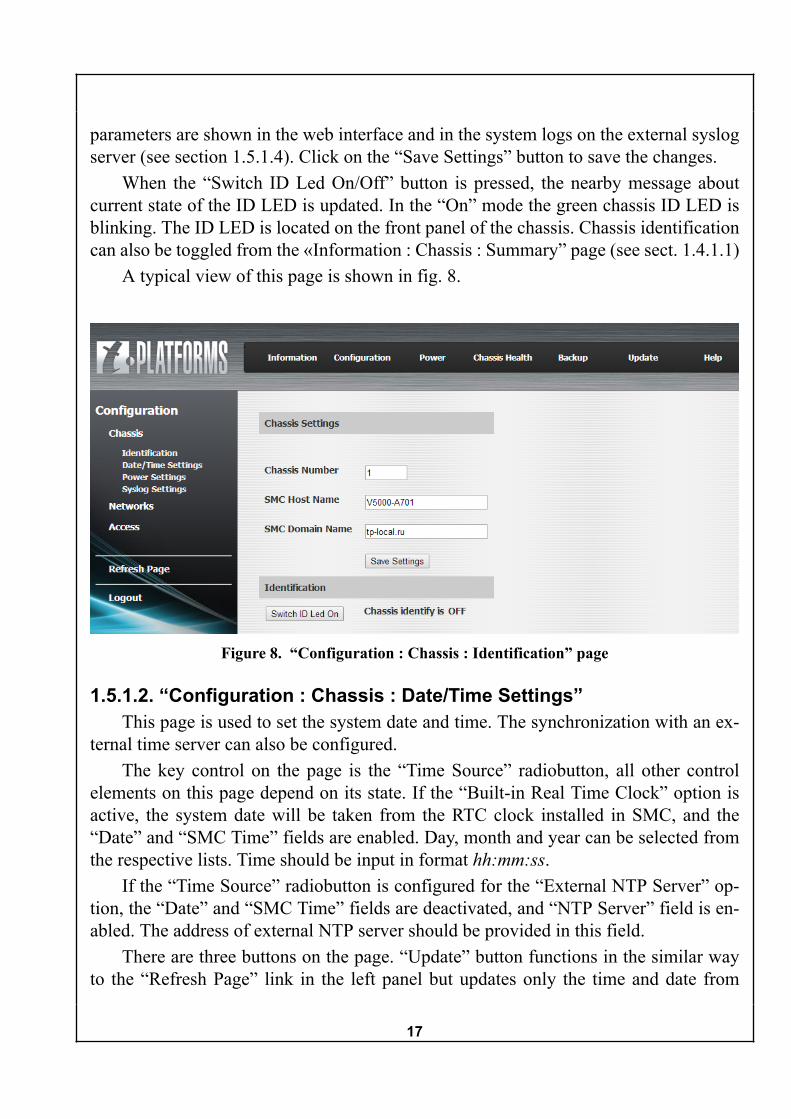
1.7.1. “Chassis Health : Chassis”The “Chassis” subsection has only one page named “Chassis Sensors”. The data
it represents is organized in a table with three columns: “Sensor Name”, “Value” and“Units” for that value. Each row shows unique measured value updated every few sec-onds. The shown parameters include temperature samples, various voltage, current andpower measurements, rotational velocity of the system and PSU fans.
The table demonstrates the following parameters:
● For each of the cooling fan modules (CFM1—CFM3):
○ Inlet (outer) fan speed.
○ Inlet Air Temperature.
○ Outlet (inner) fan speed.
● Combined CFM current (12V) and power (12V)
● Combined management current and power (5V).
● For each of the power supply modules (PSU1—PSU4):
○ Fan 1 and Fan 2 RPM measurement.
○ Input Current and Input Voltage.
○ Output Current and Output Voltage.
○ Temperature inside the PSU.
● SMC RTC Temperature.
A typical view of this page is shown in fig. 18.
29
Figure 18. “Chassis Health : Chassis Sensors” page
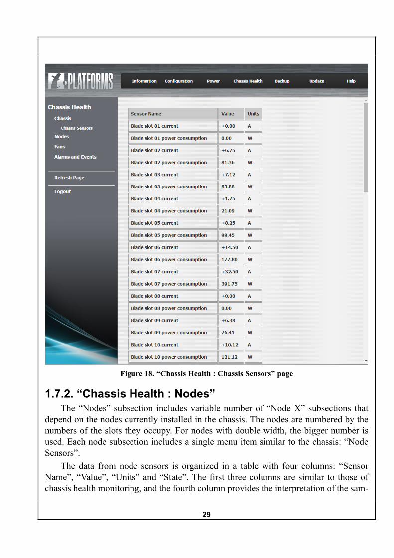
1.7.2. “Chassis Health : Nodes”The “Nodes” subsection includes variable number of “Node X” subsections that
depend on the nodes currently installed in the chassis. The nodes are numbered by thenumbers of the slots they occupy. For nodes with double width, the bigger number isused. Each node subsection includes a single menu item similar to the chassis: “NodeSensors”.
The data from node sensors is organized in a table with four columns: “SensorName”, “Value”, “Units” and “State”. The first three columns are similar to those ofchassis health monitoring, and the fourth column provides the interpretation of the sam-

30
pled parameter in terms of “ok” or “not ok”. Each row shows unique measured value up-dated every few seconds. The shown parameters include various temperature and volt-age samples.
A typical view of this menu item is shown in fig. 19.
Figure 19. “Chassis Health : Nodes : Node X : Node Sensors” page
1.7.3. “Chassis Health : Fans”This subsection is used for monitoring and controlling the cooling fan modules
(CFMs). The fan speeds are also shown among many other hardware parameters in the“Chassis Sensors” page of the “Chassis Health” section.

31
The drop down list is used to set the minimum desired duty cycle from 10% to 100%in increments of 10%.
The speeds for each of the three fan modules is shown in the table. Every CFMfeatures two fans with independent rotational speeds.
A view of the CFM monitoring and management interface is shown in fig. 20.
Figure 20. Chassis CFM monitoring and management interface
1.7.4. “Chassis Health : Alarms and Events”The “Alarms and Events” subsection hosts the logs for chassis events and system
alarms.
1.7.4.1. “Chassis Health : Alarms and Events : Events”This page shows the system event log. All system events may have or not have the
criticality level. Events without criticality level are marked as “Detected” in the “Statechange” field of the log. Critical events are marked with the state before the event andafter the event.
All events are stored in nonvolatile memory. If the event is an alarm (it is associatedwith a detected problem), then it also gets enlisted in the alarms list, if there is no relatedevent that removes the alarm. The list of active alarms can be found on the “Alarms”page. A user can clear the event log, but not the alarm log. When the critical events areclosed by related back-to-normal events, the related alarms are removed from the alarmslog. In case of power outage or SMC reboot the alarm log is cleared and rebuilt withnew valid alarms if any are present.

32
The system event log is shown in the table form. The table shows event ID, timestamp of event, source, the event description and the state change. The state change isrepresented by two columns, where the described stage change happened from the leftto right state. Valid state options are: “Normal”,“Warning”, “Critical” and “Fatal”.
Each view of the table includes ten events, the log can be scrolled back and forwardwith the links “<<Prev” and “Next>>” above the table.
The “Clear all events” button located below the table clears the entire event log.A view of the system event log is shown in fig. 21.
Figure 21. System event log view
1.7.4.2. “Chassis Health : Alarms and Events : Alarms”The “Alarms” section shows the list of active system alarms. The list of alarms is
shown in the table form. The table shows alarm ID, source, the Alarm text description andthe Severity of the alarm. Valid severity options are: “Normal”, “Warning”, “Critical”and “Fatal”.
Еach view of the list includes ten alarms, the list can be scrolled back and forwardwith the links “<<Prev” and “Next>>” above the table.

33
A view of the system alarm list is shown in fig. 22.
Figure 22. System alarm list view
1.7.4.3. “Chassis Health : Alarms and Events : SNMP_MIBs”The “SNMP_MIBs” menu item allows a user to save the archive with MIB files
that describe the structure of SMC SNMP tree. Clicking on “SNMP_MIBs” menu itembrings up a standard file saving dialog window.
1.8. “Backup”The “Backup” section is used to create or restore the backup of chassis configuration.
By default, the “Create Backup” page is active. The central panel shows the descriptionof the backup process and offers a single “Create Backup” button. Clicking on it causesthe system to generate the backup file, after some short time a dialogue window appears,so the location for the backup file can be chosen.
“Restore Backup” page offers the user to select the backup file to restore the savedsettings. The central panel provides two options for choosing the file — either the fullpath should be typed in the text field, or the file selection window should be broughtup with the “Browse” button. When the file is selected, click “Upload” button to uploadthe new firmware file.
NoteWhen the backup file is loaded, all changes made after backup operation
will be lost.

34
A view of the backup creation interface is shown in fig. 23.
Figure 23. SMC firmware settings backup creation interface
A view of the backup restoration interface is shown in fig. 24.
Figure 24. SMC firmware settings backup restoration interface
1.9. “Update”The “Update” section is used for uploading the SMC firmware updates. Choose the
file with standard file selection dialogue that is provided by your browser. When thefile is selected, click “Upload” button to upload the new firmware file. When the file isuploaded, the old firmware gets erased and the new firmware gets flashed in the memory.
WarningDespite uploaded files are checked for integrity, be sure to select proper file
to avoid system damage.
NoteThe system will be restarted when update is complete.

35
A view of the firmware update interface is shown in fig. 25.
Figure 25. SMC firmware update interface
1.10. “Help”Clicking on the “Help” section from any other section does not change the central
panel contents, but instead brings up a unique panel on the right side of the screen. Thispanel contains the help page and a link to the PDF version of current manual.
A view of the right panel is shown in fig. 26.
Figure 26. Help panel

36
Chapter 2. Command line interface2.1. Command overview
Entire system configuration can be done with the CLI commands. IMU v1.1 supportsthe following commands:
● help
● alarms
● backup
● chassis
● date
● events
● fans
● node
● passwd
● quit
● syslog
● update
Each command is described in details in the related section below.
2.2. help commandThe help command has no subcommands. The command outputs the list of CLI
commands to the console.
2.3. alarms commandThe alarms command is used to get the information on active system alarms.

37
Команда alarms поддерживает следующие субкоманды:The alarms command supports the following subcommands:
● alarms list
● alarms get <alarm_id>
Enter the alarms list command to output the list of all active alarms. The table ofactive alarms will be output to the console. For each alarm, the id, hardware id, alarmdescription and criticality level are shown.
An example of the alarms list is shown below.
v5000 cli>alarms list id HwId Alarm crit level------------------------------------------------------------ 0 SMC CIS system wrong config detected warning------------------------------------------------------------1 total active alarms
Use the alarms get <alarm_id> command, where <alarm_id> should be substitut-ed for the actual id, to see the detailed information on particular alarm.
A view of the detailed alarm description is shown below.
v5000 cli>alarms get 0 id HwId Alarm crit level------------------------------------------------------------ 0 SMC CIS system wrong config detected warning------------------------------------------------------------
2.4. backup commandThe backup command is used to create and restore the backups of the system con-
figuration.Команда backup поддерживает следующие субкоманды:The backup command supports the following subcommands:
● backup create <NFS_path>
● backup restore <NFS_path>
Use the backup create <NFS_path> command to make a backup. Valid NFS pathmust be provided in the <NFS_path> argument. The configuration backup will be savedunder that path.

38
Load the previously created configuration backup with the backup restore<NFS_path> command. Valid NFS path leading to an existing backup file must be pro-vided in the <NFS_path> argument.
2.5. chassis commandThe chassis command tunes various settings of the system chassis. When used with-
out parameters, the list of available subcommands is shown:
● identity
● info
● fru
● fwinfo
● mc
● id
● time
● net
● bmc
● psu
● power
● sdr
The description of each subcommand is given below.
2.5.1. identity subcommandThe chassis identity command is used for turning the chassis identification LED
on or off. Command chassis identity with no argument gives current state of the LED.Enter the chassis identity on to enable the LED, and chassis identity off to disable it.

39
An example output of chassis identity command is shown below.
v5000 cli>chassis identityLed ID turned off
v5000 cli>chassis identity onLed ID turned on
v5000 cli>chassis identity offLed ID turned off
2.5.2. info subcommandThe chassis info command provides information about system chassis. The dis-
played information includes the legend for the front panel and status of available nodesand power supply units.
An example output of chassis info command is shown in below.
v5000 cli>chassis infoFront View (from SMC/LED Panel side:+----+----+----+----+----+----+----+----+----+----+| | | | | | | | | | || 01 | 02 | 03 | 04 | 05 | 06 | 07 | 08 | 09 | 10 || | | | | | | | | | || | | | | | | | | | |+----+----+----+----+----+----+----+----+----+----+|eth1| PSU 1 | PSU 2 | PSU 3 | PSU 4 | x |+----+---------+---------+---------+---------+----+
Nodes: No Node Type State IP Address Netmask Def Gateway-------------------------------------------------------------------------------- 1 V200S(Intel) Ready 192.168.16.231 255.255.255.0 192.168.16.254 2 V200S(Intel) Ready 192.168.16.232 255.255.255.0 192.168.16.254 3 V200S(Intel) Ready 192.168.16.233 255.255.255.0 192.168.16.254 4,5 V200F(Intel+GPU) Ready 192.168.16.234 255.255.255.0 192.168.16.254 6 N/A No blade 0.0.0.0 0.0.0.0 0.0.0.0 7 V200S(Intel) Ready 192.168.16.235 255.255.255.0 192.168.16.254 8 N/A No blade 0.0.0.0 0.0.0.0 0.0.0.0 9 V210S(Intel) Examined 0.0.0.0 0.0.0.0 0.0.0.0 10 N/A No blade 0.0.0.0 0.0.0.0 0.0.0.0--------------------------------------------------------------------------------Power supply units:Pos PSU type PSU status Vin Iin Win Vout Iout Wout-------------------------------------------------------------------------------- 1 CAR1612FPB Normal operation 232 0 209 11 8 95 2 CAR1612FPB Normal operation 232 0 178 11 3 41 3 CAR1612FPB Normal operation 232 0 174 11 3 37 4 CAR1612FPB Normal operation 232 0 134 11 1 20--------------------------------------------------------------------------------

40
2.5.3. fru subcommandThe chassis fru command provides information about the version and manufactur-
ing date for hardware components of the chassis.An example output of chassis fru command is shown below.
v5000 cli>chassis fruChassis Type = Main Server ChassisProduct Manufacturer = T-PlatformsProduct Name = TP V5000Board Name = System Management ControllerDevice Revision = 1Board Revision = 5Board Serial = TV00C5A11212020255Board Mfg Date = Dec 2012Board Part Number = V20X-SMC-5PDB H/W revision = 5.0
2.5.4. fwinfo subcommandThe chassis fwinfo command provides information about firmware versions of chas-
sis components.An example output of chassis fwinfo command is shown below.
v5000 cli>chassis fwinfoSMC F/W Version = 1.1.0r7886Image Name = TP V5000 v1.1.0r7886Image Build Date = Wed Jul 30 21:47:04 MSK 2014PDB F/W version = 4.23r7884rc
2.5.5. mc subcommandThe chassis mc command is used for operations with the SMC controller. Two sub-
commands are supported, reboot and reset:
● chassis mc reboot reboots the controller in orderly fashion;
● chassis mc reset forcefully resets the controller.
NoteThis command does not request the confirmation before taking action.
When SMC is being restarted, the telnet/SSH connection gets interrupted.
An example output of chassis mc command is shown below. Take not that the chas-sis mc reset does not ask for confirmation in the current IMU version.

41
v5000 cli>chassis mc rebootv5000 cli>umount: /dev/pts: Device or resource busyumount: /sys: Device or resource busyumount: /dev: Device or resource busyumount: /: Device or resource busyumount: /: Device or resource busy
v5000 cli>chassis mc reset
2.5.6. id subcommandThe chassis id command is used for operations with the chassis identifier. Use the
chassis id command and no argument to get the current identifier value. The chassisid <value> command can be used to specify the new identifier equal to the <value>argument.
An example output of chassis id command is shown below.
v5000 cli>chassis idChassis id: 1
v5000 cli>chassis id 2chassis ID is set to 2
2.5.7. time subcommandThe chassis time command is used for synchronization of local system time with
the external NTP server. Two subcommands are supported, server and time:
● chassis time server [ipaddr|server_name] specifies the NTP server address in formof IP address or hostname. If used without argument, outputs current value of NTPserver address setting.
● chassis time ntp [on|off] enables or disables the NTP server time synchronization.
An example output of chassis time command is shown below.

42
v5000 cli>chassis timeAvailable commands: ntp [on|off] : Turn on|off ntp sync server [ipaddr|server_name] : Set/get NTP server addr
v5000 cli>chassis time ntpChassis time source: NTP
v5000 cli>chassis time serverChassis ntpserver: 192.168.5.5
v5000 cli>chassis time serverChassis ntpserver: 192.168.5.5
v5000 cli>chassis time server 192.168.5.2chassis ntpserver is set to 192.168.5.2
2.5.8. net subcommandThe chassis net command is used for tuning the network configuration of the SMC
controller. This command supports several subcommands:
● chassis net print [saved|actual]
● chassis net mode [dhcp|local]
● chassis net ipaddr [ipaddr]
● chassis net netmask [netmask]
● chassis net gateway [ipaddr]
● chassis net hostname [hostname]
● chassis net domain [domain]
● chassis net dns [dnsid ipaddr]
● chassis net apply
The chassis net command has a special feature. There is an actual SMC networkconfiguration that defines the actual network connection parameters. Any modificationsin the network settings get stored in the saved configuration. The saved configurationbecomes actual when SMC or chassis get restarted, or when the chassis net apply com-mand is executed.

43
If the network configuration is being changed for experimental purposes and thechanges should not be preserved — make sure to change the settings back to the actualconfiguration values. Otherwise the changes will be applied upon SMC or chassis restart,which can make remote SMC access impossible in certain cases.
All supported subcommands are described below.
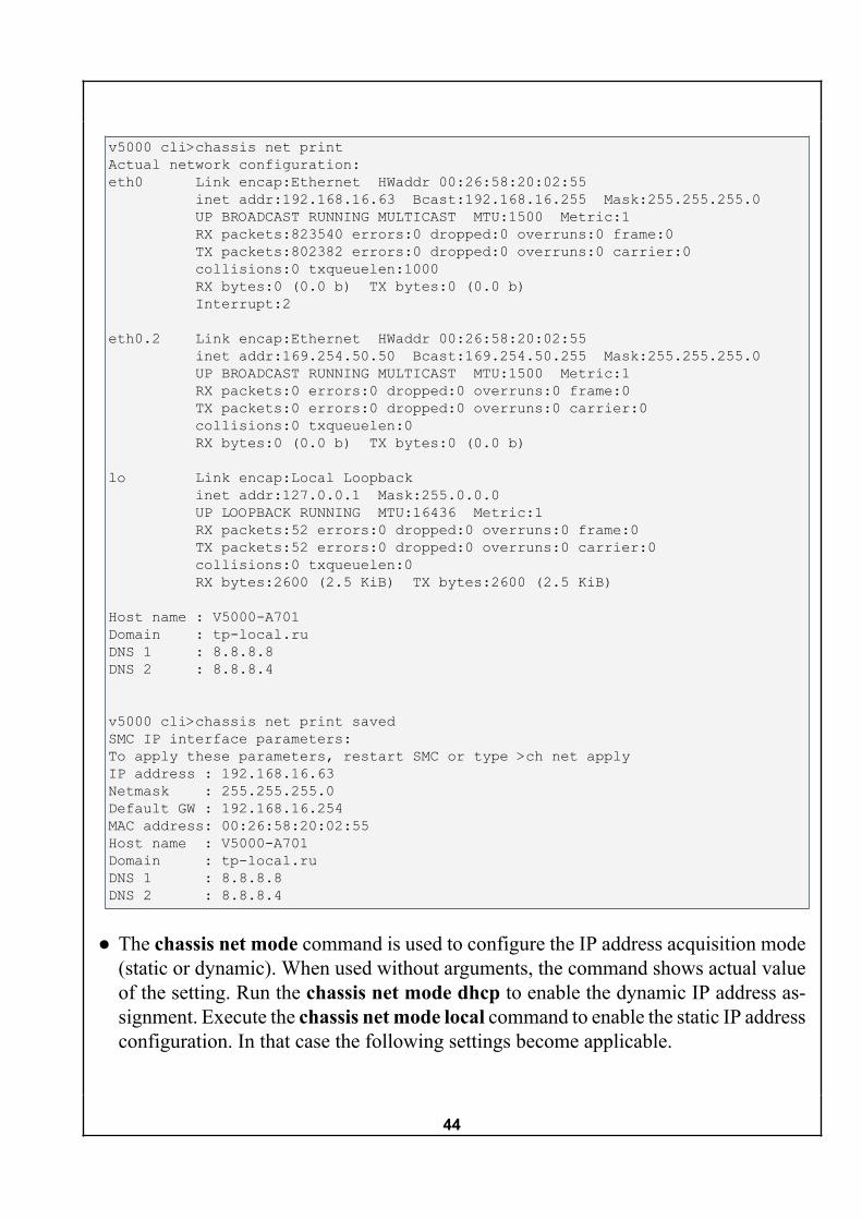
● The chassis net print actual command outputs the actual SMC network configura-tion. The same configuration is printed when the chassis net print command is exe-cuted without additional arguments. The chassis net print saved command prints thesaved configuration.
An example output of the chassis net print command is shown below
44
v5000 cli>chassis net printActual network configuration:eth0 Link encap:Ethernet HWaddr 00:26:58:20:02:55 inet addr:192.168.16.63 Bcast:192.168.16.255 Mask:255.255.255.0 UP BROADCAST RUNNING MULTICAST MTU:1500 Metric:1 RX packets:823540 errors:0 dropped:0 overruns:0 frame:0 TX packets:802382 errors:0 dropped:0 overruns:0 carrier:0 collisions:0 txqueuelen:1000 RX bytes:0 (0.0 b) TX bytes:0 (0.0 b) Interrupt:2
eth0.2 Link encap:Ethernet HWaddr 00:26:58:20:02:55 inet addr:169.254.50.50 Bcast:169.254.50.255 Mask:255.255.255.0 UP BROADCAST RUNNING MULTICAST MTU:1500 Metric:1 RX packets:0 errors:0 dropped:0 overruns:0 frame:0 TX packets:0 errors:0 dropped:0 overruns:0 carrier:0 collisions:0 txqueuelen:0 RX bytes:0 (0.0 b) TX bytes:0 (0.0 b)
lo Link encap:Local Loopback inet addr:127.0.0.1 Mask:255.0.0.0 UP LOOPBACK RUNNING MTU:16436 Metric:1 RX packets:52 errors:0 dropped:0 overruns:0 frame:0 TX packets:52 errors:0 dropped:0 overruns:0 carrier:0 collisions:0 txqueuelen:0 RX bytes:2600 (2.5 KiB) TX bytes:2600 (2.5 KiB)
Host name : V5000-A701Domain : tp-local.ruDNS 1 : 8.8.8.8DNS 2 : 8.8.8.4
v5000 cli>chassis net print savedSMC IP interface parameters:To apply these parameters, restart SMC or type >ch net applyIP address : 192.168.16.63Netmask : 255.255.255.0Default GW : 192.168.16.254MAC address: 00:26:58:20:02:55Host name : V5000-A701Domain : tp-local.ruDNS 1 : 8.8.8.8DNS 2 : 8.8.8.4
● The chassis net mode command is used to configure the IP address acquisition mode(static or dynamic). When used without arguments, the command shows actual valueof the setting. Run the chassis net mode dhcp to enable the dynamic IP address as-signment. Execute the chassis net mode local command to enable the static IP addressconfiguration. In that case the following settings become applicable.

45
An example of the chassis net mode command functionality is shown below.
v5000 cli>chassis net modeNetwork configuration mode: local
v5000 cli>chassis net mode dhcpDHCP client enabled, config paramters will be received from DHCP server
v5000 cli>chassis net mode localDHCP client disabled, please set network parameters locally and 'apply'
● The chassis net ipaddr command without argument shows the actual IP address ofthe SMC controller. The IP address can be set manually with the chassis net ipaddr<IP_address> command, where the argument <IP_address> contains a valid IP ad-dress.
An example of the chassis net ipaddr command functionality is shown below.
v5000 cli>chassis net ipaddrChassis ipaddr: 192.168.16.63
v5000 cli>chassis net ipaddr 192.168.16.64
v5000 cli>chassis net ipaddrChassis ipaddr: 192.168.16.64
● The chassis net netmask command without argument shows the actual netmask ofthe SMC controller. The netmask can be set manually with the chassis net netmask<Netmask> command, where the argument <Netmask> contains a valid netmask.
An example of the chassis net netmask command functionality is shown below.
v5000 cli>chassis net netmaskChassis netmask: 255.255.255.0
v5000 cli>chassis net netmask 255.255.0.0
v5000 cli>chassis net netmaskChassis netmask: 255.255.0.0
● The chassis net gateway command without argument shows the actual gateway ad-dress of the SMC controller. The gateway can be set manually with the chassis netgateway <Gateway> command, where the argument <Gateway> contains a validgateway address.
An example of the chassis net gateway command functionality is shown below.

46
v5000 cli>chassis net gatewayChassis gateway: 192.168.16.254
v5000 cli>chassis net gateway 192.168.16.153
v5000 cli>chassis net gatewayChassis gateway: 192.168.16.153
● The chassis net hostname command without argument shows the actual hostnameof the SMC controller. The hostname can be set manually with the chassis net host-name <Hostname> command, where the argument <Hostname> contains a validhostname.
An example of the chassis net hostname command functionality is shown below.
v5000 cli>chassis net hostnameChassis hostname: V5000-A701
v5000 cli>chassis net hostname V5000-A701-NEW
v5000 cli>chassis net hostnameChassis hostname: V5000-A701-NEW
● The chassis net domain command without argument shows the actual domain of theSMC controller. The domain can be set manually with the chassis net domain <Do-main> command, where the argument <Domain> contains a valid domain.
An example of the chassis net domain command functionality is shown below.
v5000 cli>chassis net domainChassis domain: example.com
v5000 cli>chassis net domain example-new.com
v5000 cli>chassis net domainChassis domain: example-new.com
● An example of the chassis net dns command functionality is shown below.
v5000 cli>chassis net dnsChassis dns1 addr: 8.8.8.8Chassis dns2 addr: 8.8.8.4
v5000 cli>chassis net dns 2 10.10.10.10
v5000 cli>chassis net dnsChassis dns1 addr: 8.8.8.8Chassis dns2 addr: 10.10.10.10
47
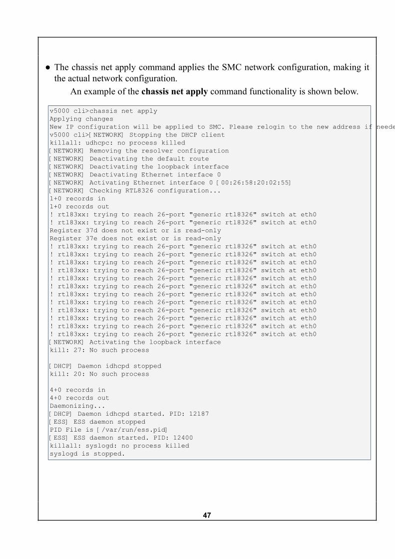
● The chassis net apply command applies the SMC network configuration, making itthe actual network configuration.
An example of the chassis net apply command functionality is shown below.
v5000 cli>chassis net applyApplying changesNew IP configuration will be applied to SMC. Please relogin to the new address if needed.v5000 cli>[NETWORK] Stopping the DHCP clientkillall: udhcpc: no process killed[NETWORK] Removing the resolver configuration[NETWORK] Deactivating the default route[NETWORK] Deactivating the loopback interface[NETWORK] Deactivating Ethernet interface 0[NETWORK] Activating Ethernet interface 0 [00:26:58:20:02:55][NETWORK] Checking RTL8326 configuration...1+0 records in1+0 records out! rtl83xx: trying to reach 26-port "generic rtl8326" switch at eth0! rtl83xx: trying to reach 26-port "generic rtl8326" switch at eth0Register 37d does not exist or is read-onlyRegister 37e does not exist or is read-only! rtl83xx: trying to reach 26-port "generic rtl8326" switch at eth0! rtl83xx: trying to reach 26-port "generic rtl8326" switch at eth0! rtl83xx: trying to reach 26-port "generic rtl8326" switch at eth0! rtl83xx: trying to reach 26-port "generic rtl8326" switch at eth0! rtl83xx: trying to reach 26-port "generic rtl8326" switch at eth0! rtl83xx: trying to reach 26-port "generic rtl8326" switch at eth0! rtl83xx: trying to reach 26-port "generic rtl8326" switch at eth0! rtl83xx: trying to reach 26-port "generic rtl8326" switch at eth0! rtl83xx: trying to reach 26-port "generic rtl8326" switch at eth0! rtl83xx: trying to reach 26-port "generic rtl8326" switch at eth0! rtl83xx: trying to reach 26-port "generic rtl8326" switch at eth0! rtl83xx: trying to reach 26-port "generic rtl8326" switch at eth0[NETWORK] Activating the loopback interfacekill: 27: No such process
[DHCP] Daemon idhcpd stoppedkill: 20: No such process
4+0 records in4+0 records outDaemonizing...[DHCP] Daemon idhcpd started. PID: 12187[ESS] ESS daemon stoppedPID File is [/var/run/ess.pid][ESS] ESS daemon started. PID: 12400killall: syslogd: no process killedsyslogd is stopped.

48
2.5.9. bmc subcommandThe chassis bmc command is used to configure the network connections of node
BMC controllers. This command supports several subcommands:
● chassis bmc list
● chassis bmc mode [active|passive]
● chassis bmc ipaddr <group> [ipaddr|dhcp]
● chassis bmc netmask <group> [netmask]
● chassis bmc gateway <group> [ipaddr]
● chassis bmc members <group> [memblist]
● chassis bmc apply
All subcommands are described below.
● The chassis bmc list command prints the table of groups and their nodes. The IPaddress acquisition mode, first IP address of the interval, the netmask and gatewayare shown for each group.
An example of the chassis bmc list command functionality is shown below.
v5000 cli>chassis bmc listGN IP src IP addr Netmask Gateway 1 2 3 4 5 6 7 8 9 10-------------------------------------------------------------------------------- 1 static 192.168.16.231 255.255.255.0 192.168.16.254 x x x . x . x . . . 2 none none none none . . . x . x . x x x 3 none none none none . . . . . . . . . . 4 none none none none . . . . . . . . . . 5 none none none none . . . . . . . . . . 6 none none none none . . . . . . . . . . 7 none none none none . . . . . . . . . . 8 none none none none . . . . . . . . . . 9 none none none none . . . . . . . . . .10 none none none none . . . . . . . . . .--------------------------------------------------------------------------------
● The chassis bmc members command is used for configuration of group membership.Use the chassis bmc members <groupN> command to print the members of the
group with the number <groupN>.

49
The membership list can be configured with the chassis bmc members<groupN> <membrlist> command, where <groupN> is the group number, and<membrlist> is the space-separated list of the group members.
An example of the chassis bmc members command functionality is shown below.
v5000 cli>chassis bmc members 1Group 1 members: 1 2 3 5 7
v5000 cli>chassis bmc members 2Group 2 members: 4 6 8 9 10
v5000 cli>chassis bmc members 3 1 4Group 3 members set to 1 4 (ch bmc apply - to reconfigure nodes)
v5000 cli>chassis bmc members 1Group 1 members: 2 3 5 7
v5000 cli>chassis bmc members 2Group 2 members: 6 8 9 10
v5000 cli>chassis bmc members 3Group 3 members: 1 4
● The chassis bmc mode command configures the mode of interaction with the BMCcontrollers of compute nodes.
The chassis bmc mode active command enables the mode when SMC definesthe network configuration for the node BMCs. The configuration itself is set up withother “chassis bmc” subcommands.
The chassis bmc mode passive command allows the node BMCs define theirown network configuration.
An example of the chassis bmc mode command functionality is shown below.
v5000 cli>chassis bmc mode
IMU configures BMC IP parameters (Active mode)v5000 cli>chassis bmc mode passivekill: 20: No such process
4+0 records in4+0 records outIMU is switched to passive modev5000 cli>Daemonizing...
v5000 cli>chassis bmc mode activeIMU is switched to active mode. Please set network parameters for nodes BMC and apply changes

50
● The chassis bmc ipaddr command is used to specify the starting IP address for thegroup of nodes specified by the <group> argument.
An example of the chassis bmc ipaddr command functionality is shown below.
v5000 cli>chassis bmc ipaddr 1Group 1 starting IP: 192.168.16.231
v5000 cli>chassis bmc ipaddr 1 192.168.16.200Group 1 starting IP set to: 192.168.16.200
● The chassis bmc netmask <group> <Netmask> command is used to configure thenetmask for the group specified by the <group> argument. The netmask is providedwith the <Netmask> argument.
An example of the chassis bmc netmask command functionality is shown below.
v5000 cli>chassis bmc netmask 1Group 1 netmask: 255.255.255.0
v5000 cli>chassis bmc netmask 1 255.255.0.0Group 1 netmask set to: 255.255.0.0
● The chassis bmc gateway command is used for _An example of the chassis bmc gateway command functionality is shown below.
v5000 cli>chassis bmc gateway 1Group 1 gateway: 192.168.16.254
v5000 cli>chassis bmc gateway 1 192.168.16.153Group 1 gateway set to: 192.168.16.153
● The chassis bmc apply writes the BMC configuration changes to the actual config-uration.
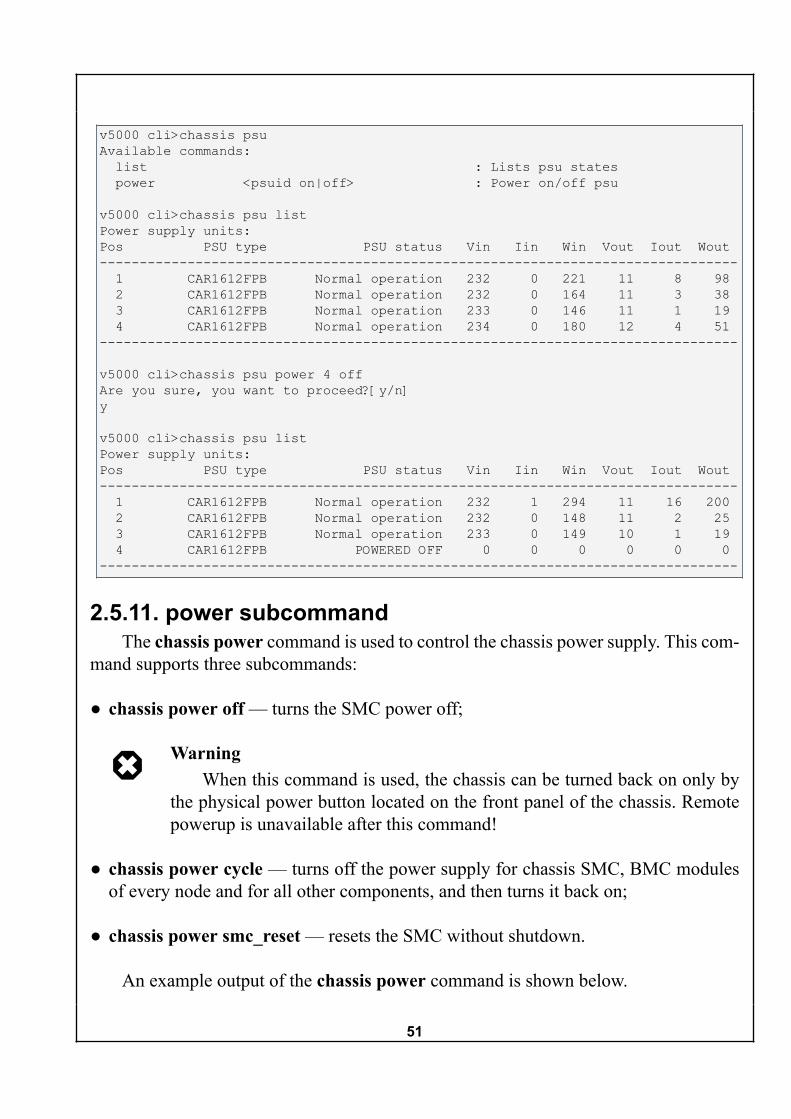
2.5.10. psu subcommandThe chassis psu command is used for interaction with the power supply units. This
command supports two subcommands, list and power:
● chassis psu list outputs information about available power supply units;
● chassis psu power <psuid on|off> turns on or off the PSU specified by the psuidargument.
An example output of chassis psu command is shown below.
51
v5000 cli>chassis psuAvailable commands: list : Lists psu states power <psuid on|off> : Power on/off psu
v5000 cli>chassis psu listPower supply units:Pos PSU type PSU status Vin Iin Win Vout Iout Wout-------------------------------------------------------------------------------- 1 CAR1612FPB Normal operation 232 0 221 11 8 98 2 CAR1612FPB Normal operation 232 0 164 11 3 38 3 CAR1612FPB Normal operation 233 0 146 11 1 19 4 CAR1612FPB Normal operation 234 0 180 12 4 51--------------------------------------------------------------------------------
v5000 cli>chassis psu power 4 offAre you sure, you want to proceed?[y/n]y
v5000 cli>chassis psu listPower supply units:Pos PSU type PSU status Vin Iin Win Vout Iout Wout-------------------------------------------------------------------------------- 1 CAR1612FPB Normal operation 232 1 294 11 16 200 2 CAR1612FPB Normal operation 232 0 148 11 2 25 3 CAR1612FPB Normal operation 233 0 149 10 1 19 4 CAR1612FPB POWERED OFF 0 0 0 0 0 0--------------------------------------------------------------------------------
2.5.11. power subcommandThe chassis power command is used to control the chassis power supply. This com-
mand supports three subcommands:
● chassis power off — turns the SMC power off;
WarningWhen this command is used, the chassis can be turned back on only by
the physical power button located on the front panel of the chassis. Remotepowerup is unavailable after this command!
● chassis power cycle — turns off the power supply for chassis SMC, BMC modulesof every node and for all other components, and then turns it back on;
● chassis power smc_reset — resets the SMC without shutdown.
An example output of the chassis power command is shown below.

52
v5000 cli>chassis power smc_resetv5000 cli>umount: /dev/pts: Device or resource busyumount: /sys: Device or resource busyumount: /dev: Device or resource busyumount: /: Device or resource busyumount: /: Device or resource busy
v5000 cli>chassis power cycleAre you sure, you want to proceed?[y/n]y
v5000 cli>chassis power offAre you sure, you want to proceed?[y/n]y
2.5.12. sdr subcommandThe chassis sdr command outputs data from various sensors embedded in chassis
components. The provided information includes data on temperatures, voltages, currents,and fan speeds.
An example output of the chassis sdr command is shown below. The list of sensorsis very long, so only a part of command output is shown.
v5000 cli>chassis sdrPSU1 Input Voltage : +233.00 VPSU2 Input Voltage : +232.25 VPSU3 Input Voltage : +233.25 VPSU4 Input Voltage : +233.25 VPSU1 Output Voltage : +11.89 VPSU2 Output Voltage : +11.76 VPSU3 Output Voltage : +11.21 VPSU4 Output Voltage : +11.38 VPSU1 Fan 1 : 7040 RPMPSU2 Fan 1 : 6720 RPMPSU3 Fan 1 : 6272 RPMPSU4 Fan 1 : 6272 RPMPSU1 Fan 2 : 6592 RPMPSU2 Fan 2 : 6592 RPMPSU3 Fan 2 : 6720 RPMPSU4 Fan 2 : 6880 RPMPSU1 Temperature : +26.0 CPSU2 Temperature : +26.0 CPSU3 Temperature : +26.0 CPSU4 Temperature : +26.0 CCombined management power (5V) : 29.61 WCombined CFM power (12V) : 42.69 W…
2.6. date commandThe date command is used to output or change the current system date and time.

53
When entered without subcommands, the date command outputs the current systemdate and time.
To update the current date and time, use the date [MMDDhhmm[[CC]YY][.ss]]command, where MM is the month, DD is the day, hh — hours, mm — minutes,CC — first two digits of the year, YY — last two digits of the year, ss — seconds.
Updated system date and time values are shown in the console when the commandis entered.
An example of the date command functionality is shown below.
v5000 cli>dateMon Aug 4 09:58:40 UTC 2014
v5000 cli>date 080516502014Date and time controlled by NTP!
2.7. events commandThe events command is used for operations with the system event log. For each
event, the id, time in UTC format, hardware id, event description, prior and posteriorcriticality levels are shown.
The events command supports three subcommands:
● events list
● events get <tail> <count>
● events clear
Use events list command to see the full system event log. Note that the log mightbe very long.
An example output of the events list command is shown below. The example demon-strates only head and tail of the event list which includes 611 lines in total.

54
v5000 cli>events list id Time(UTC) HwId Event Old state New state-------------------------------------------------------------------------------- 0 14-08-04 08:58:19 SMC Chassis start detected 1 14-08-04 08:58:19 SMC CIS wrong config state warning 2 14-08-04 08:58:19 BL1 New BMC found event detected 3 14-08-04 08:58:20 BL2 New BMC found event detected… 607 14-08-04 10:11:32 BL9 BMC Ip connectivity change critical 608 14-08-04 10:11:45 BL9 BMC Ip connectivity change critical 609 14-08-04 10:11:46 BL9 BMC Ip connectivity change critical 610 14-08-04 10:12:00 BL9 BMC Ip connectivity change critical 611 14-08-04 10:12:00 BL9 BMC Ip connectivity change critical--------------------------------------------------------------------------------
Use the events get <tail> <count> command to get only the selected events fromthe log. The <tail> argument specifies how many lines should be omitted from the logend, and the <count> argument defines how many events should be shown. For example,the events get 0 5 command shows the last 5 events from the log, and events get 10 15gives 15 events that precede the 10th from the log end, namely from 16th to 11th logentries counting from the end.
An example output of the events get command is shown below.
v5000 cli>events get 0 5 id Time(UTC) HwId Event Old state New state-------------------------------------------------------------------------------- 607 14-08-04 10:11:32 BL9 BMC Ip connectivity change critical 608 14-08-04 10:11:45 BL9 BMC Ip connectivity change critical 609 14-08-04 10:11:46 BL9 BMC Ip connectivity change critical 610 14-08-04 10:12:00 BL9 BMC Ip connectivity change critical 611 14-08-04 10:12:00 BL9 BMC Ip connectivity change critical--------------------------------------------------------------------------------

55
v5000 cli>events get 10 15 id Time(UTC) HwId Event Old state New state-------------------------------------------------------------------------------- 587 14-08-04 10:09:01 BL9 BMC Ip connectivity change critical 588 14-08-04 10:09:16 BL9 BMC Ip connectivity change critical 589 14-08-04 10:09:17 BL9 BMC Ip connectivity change critical 590 14-08-04 10:09:31 BL9 BMC Ip connectivity change critical 591 14-08-04 10:09:31 BL9 BMC Ip connectivity change critical 592 14-08-04 10:09:46 BL9 BMC Ip connectivity change critical 593 14-08-04 10:09:48 BL9 BMC Ip connectivity change critical 594 14-08-04 10:10:01 BL9 BMC Ip connectivity change critical 595 14-08-04 10:10:02 BL9 BMC Ip connectivity change critical 596 14-08-04 10:10:16 BL9 BMC Ip connectivity change critical 597 14-08-04 10:10:16 BL9 BMC Ip connectivity change critical 598 14-08-04 10:10:31 BL9 BMC Ip connectivity change critical 599 14-08-04 10:10:32 BL9 BMC Ip connectivity change critical 600 14-08-04 10:10:46 BL9 BMC Ip connectivity change critical 601 14-08-04 10:10:46 BL9 BMC Ip connectivity change critical--------------------------------------------------------------------------------
Use the events clear command to clear the system event log.An example output of the events clear command is shown below.
v5000 cli>events clearEvent log cleared
2.8. fans commandThe fans command is used to output the velocities of system fans or to configure
the minimal velocity threshold for the system fans.The fans command supports two subcommands:
● fans info
● fans pwm <duty_cycle>
Use the fans info command to output current velocities of the system fans. Theconsole will report on all available system fans (CFM1—CFM3). Two values are outputfor each fan — for the inner and outer rotors.
An example output produced by the fans info command is shown below.

56
v5000 cli>fans infoCurrent FAN speed:CFM3 Inlet (outer) fan speed : 2956 RPMCFM3 Outlet (inner) fan speed : 1884 RPMCFM2 Inlet (outer) fan speed : 2991 RPMCFM2 Outlet (inner) fan speed : 1909 RPMCFM1 Inlet (outer) fan speed : 2999 RPMCFM1 Outlet (inner) fan speed : 1838 RPM
Use the fans pwm <duty_percent> command to setup the minimal threshold forthe fan velocity. The <duty_percent> argument ranges from 0 to 100 and means theduty cycle of the fans in percents. When the command is entered, the console shows amessage similar to “Minimal fan duty is set to ### percents”, where ### corresponds tothe configured duty cycle.
An example output of the fans pwm command is shown below.
v5000 cli>fans pwm 50Minimal fan duty is set to 50 percents
2.9. node commandThe node command provides information about available compute nodes and offers
node management options. When used without subcommands, the list of available sub-commands is shown:
● node list
● node <number> info
● node <number> fru
● node <number> mc info
● node <number> bmc
● node <number> mac
● node <number> power
● node <number> sdr
The description of each subcommand is given below.
57
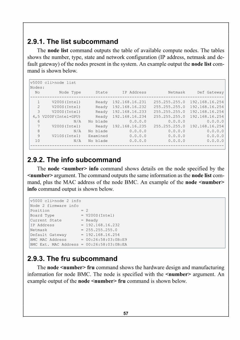
2.9.1. The list subcommandThe node list command outputs the table of available compute nodes. The tables
shows the number, type, state and network configuration (IP address, netmask and de-fault gateway) of the nodes present in the system. An example output the node list com-mand is shown below.
v5000 cli>node listNodes: No Node Type State IP Address Netmask Def Gateway-------------------------------------------------------------------------------- 1 V200S(Intel) Ready 192.168.16.231 255.255.255.0 192.168.16.254 2 V200S(Intel) Ready 192.168.16.232 255.255.255.0 192.168.16.254 3 V200S(Intel) Ready 192.168.16.233 255.255.255.0 192.168.16.254 4,5 V200F(Intel+GPU) Ready 192.168.16.234 255.255.255.0 192.168.16.254 6 N/A No blade 0.0.0.0 0.0.0.0 0.0.0.0 7 V200S(Intel) Ready 192.168.16.235 255.255.255.0 192.168.16.254 8 N/A No blade 0.0.0.0 0.0.0.0 0.0.0.0 9 V210S(Intel) Examined 0.0.0.0 0.0.0.0 0.0.0.0 10 N/A No blade 0.0.0.0 0.0.0.0 0.0.0.0--------------------------------------------------------------------------------
2.9.2. The info subcommandThe node <number> info command shows details on the node specified by the
<number> argument. The command outputs the same information as the node list com-mand, plus the MAC address of the node BMC. An example of the node <number>info command output is shown below.
v5000 cli>node 2 infoNode 2 firmware infoPosition = 2Board Type = V200S(Intel)Current State = ReadyIP Address = 192.168.16.232Netmask = 255.255.255.0Default Gateway = 192.168.16.254BMC MAC Address = 00:26:58:03:0B:E9BMC Ext. MAC Address = 00:26:58:03:0B:EA
2.9.3. The fru subcommandThe node <number> fru command shows the hardware design and manufacturing
information for node BMC. The node is specified with the <number> argument. Anexample output of the node <number> fru command is shown below.

58
v5000 cli>node 7 fruChassis Type = SubChassisChassis Part Number =Chassis Serial =Chassis Info Checksum = FAILED (d1)Board Mfg Date = Fri Oct 5 10:44:00 2012Board Mfg = T-PlatformsBoard Product = V200Board Serial = TV00D4O10812010058Board Part Number = V200F3DBoard Info Checksum = FAILED (d2)Product Manufacturer = T-PlatformsProduct Name = V-Class V200x Comp. Mod.Product Part Number = V200xProduct Version = DProduct Serial =Product Info Checksum = FAILED (f8)
2.9.4. The mc info subcommandThe node <number> mc info command outputs information about the BMC
firmware of the node specified with the <number> argument. An example output of thenode <number> mc info command is shown below.
v5000 cli>node 3 mc infoNode 3 firmware infoDevice Id = 32Device revision = 1Firmware revision = 1.10IPMI Version = 2.0Supported options = Sensor Device SDR Repository Device SEL Device FRU Inventory Device IPMB Event Receiver IPMB Event Generator Bridge Chassis DeviceVendor = T-PlatformsProduct = V200S(Intel)AUX Firmware Rev = 00 00 00 00
2.9.5. The bmc subcommandThe node <number> bmc command when used without argument outputs the list
of available subcommands for node BMC management:
● node <number> bmc mode — outputs the IP address acquisition mode that BMC ofthe node <number> is configured to use.
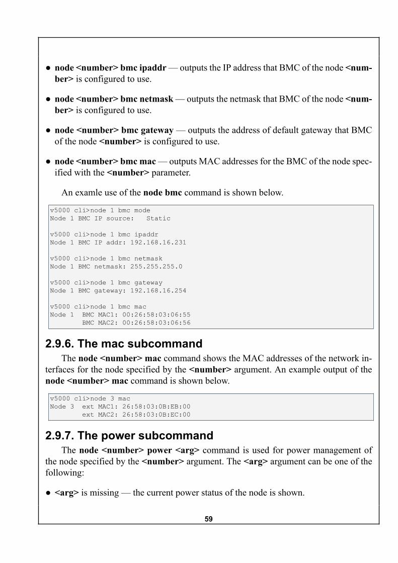
59
● node <number> bmc ipaddr — outputs the IP address that BMC of the node <num-ber> is configured to use.
● node <number> bmc netmask — outputs the netmask that BMC of the node <num-ber> is configured to use.
● node <number> bmc gateway — outputs the address of default gateway that BMCof the node <number> is configured to use.
● node <number> bmc mac — outputs MAC addresses for the BMC of the node spec-ified with the <number> parameter.
An examle use of the node bmc command is shown below.
v5000 cli>node 1 bmc modeNode 1 BMC IP source: Static
v5000 cli>node 1 bmc ipaddrNode 1 BMC IP addr: 192.168.16.231
v5000 cli>node 1 bmc netmaskNode 1 BMC netmask: 255.255.255.0
v5000 cli>node 1 bmc gatewayNode 1 BMC gateway: 192.168.16.254
v5000 cli>node 1 bmc macNode 1 BMC MAC1: 00:26:58:03:06:55 BMC MAC2: 00:26:58:03:06:56
2.9.6. The mac subcommandThe node <number> mac command shows the MAC addresses of the network in-
terfaces for the node specified by the <number> argument. An example output of thenode <number> mac command is shown below.
v5000 cli>node 3 macNode 3 ext MAC1: 26:58:03:0B:EB:00 ext MAC2: 26:58:03:0B:EC:00
2.9.7. The power subcommandThe node <number> power <arg> command is used for power management of
the node specified by the <number> argument. The <arg> argument can be one of thefollowing:
● <arg> is missing — the current power status of the node is shown.

60
● on — the node power will be turned on;
● off — the node power will be turned off;
● reset — the node will be reset as if the physical reset button was pressed.
● cycle — the node will be orderly shutdown and started, as if the subcommands offand on were run in sequence.
● shutdown — an orderly shutdown of the node through the ACPI Shutdown command.
An example of the functionality of the node <number> power <arg> commandis shown below.
v5000 cli>node 1 powerNode 1:Node power status = OffNode power supply = OnNode power consuption = 0.25A
v5000 cli>node 1 power on
v5000 cli>node 1 powerNode 1:Node power status = OnNode power supply = OnNode power consuption = 14.37A
v5000 cli>node 1 powerNode 1:Node power status = OnNode power supply = OnNode power consuption = 5.25A
v5000 cli>node 1 power cycle
v5000 cli>node 1 power reset
v5000 cli>node 1 power shutdown
v5000 cli>node 1 power on
v5000 cli>node 1 power off
v5000 cli>node 1 powerNode 1:Node power status = OffNode power supply = OnNode power consuption = 0.25A

61
2.9.8. The sdr subcommandThe node <number> sdr command provides the data from node sensors for the node
specified by the <number> argument. The data is organized in a table with six columns:Sensor Name, Value, Units, State, Min and Max. The first three columns show measure-ments provided by particular sensors, and the fourth column provides the interpretationof the sampled parameter in terms of ”ok“ or ”not ok“. Each row shows unique measuredvalue. The shown parameters include various temperature and voltage samples.
An example output of the node <number> sdr command is shown below.

62
v5000 cli>node 7 sdr
Name Value Unit State Min Max---------------------------------------------------------------CPU0 40.00 degrees C ok -128.00 127.00CPU1 34.00 degrees C ok -128.00 127.00VRD0 37.00 degrees C ok -128.00 127.00VRD1 30.00 degrees C ok -128.00 127.00Inlet 29.00 degrees C ok -128.00 127.00PCH 35.00 degrees C ok -128.00 127.00Outlet 42.00 degrees C ok -128.00 127.00IB 37.00 degrees C ok -128.00 127.00DIM_A0_CPU0 32.00 degrees C ok -128.00 127.00DIM_A1_CPU0 32.00 degrees C ok -128.00 127.00DIM_B0_CPU0 32.00 degrees C ok -128.00 127.00DIM_B1_CPU0 31.00 degrees C ok -128.00 127.00DIM_C0_CPU0 32.00 degrees C ok -128.00 127.00DIM_C1_CPU0 33.00 degrees C ok -128.00 127.00DIM_D0_CPU0 32.00 degrees C ok -128.00 127.00DIM_D1_CPU0 32.00 degrees C ok -128.00 127.00DIM_E0_CPU1 31.00 degrees C ok -128.00 127.00DIM_E1_CPU1 31.00 degrees C ok -128.00 127.00DIM_F0_CPU1 31.00 degrees C ok -128.00 127.00DIM_F1_CPU1 30.00 degrees C ok -128.00 127.00DIM_G0_CPU1 30.00 degrees C ok -128.00 127.00DIM_G1_CPU1 30.00 degrees C ok -128.00 127.00DIM_H0_CPU1 30.00 degrees C ok -128.00 127.00DIM_H1_CPU1 30.00 degrees C ok -128.00 127.00VTT 1.05 Volts ok 0.01 2.55VBAT 3.14 Volts ok 0.02 5.103VSB 3.12 Volts ok 0.02 5.10+3.3V 3.34 Volts ok 0.02 5.10+5V 5.06 Volts ok 0.03 8.16+12V 11.88 Volts ok 0.12 30.60HW3V 3.14 Volts ok 0.02 5.10Ram_AB_Volt 1.51 Volts ok 0.01 2.55Ram_CD_Volt 1.51 Volts ok 0.01 2.55Ram_EF_Volt 1.51 Volts ok 0.01 2.55Ram_GH_Volt 1.51 Volts ok 0.01 2.55PCH_Volt 1.11 Volts ok 0.01 2.55---------------------------------------------------------------Total 38 sensors
2.10. passwd commandThe passwd command is used to change the password for the current user account.
Follow these steps:
1. Enter the passwd command. The prompt for the old password will be shown.

63
2. Enter the old password. You will be prompted for the new password. The pass-word can contain lowercase and uppercase Latin characters, numbers and punctua-tion marks.
3. Enter the new password. The system will require to enter it the second time.
After that you'll see one of the following messages:
● “They don't match, sorry” — there is a difference between the new password inputs.
● “Old password is incorrect” — the old password was not provided correctly.
● “Password for user <username> changed” — the password for the <username>account has been updated.
2.11. quit commandThe quit command has no subcommands. The command immediately breaks the
console connection.
2.12. syslog commandКоманда syslog предназначена для управления системным журналом событий.
Для ведения журнала событий необходимо указать IP-адрес, по которому будетразмещён журнал.
The syslog command supports several subcommands:
● syslog status — shows the status of system event logging and IP address where thelog is maintained.
● syslog remoteIp <ip> — if the <ip> parameter is not given, then the current setting isshown; if a valid IP address is provided as the <ip> parameter, the setting is updated.
● syslog enable — the system event logging is enabled.
● syslog disable — the system event logging is disabled.
An example of syslog command functionality is shown below.

64
v5000 cli>syslog statusRemote syslog: disabledSyslog to IP: none
v5000 cli>syslog enableRemote syslog enabled, but remote server ip is not configured
v5000 cli>syslog remoteIp 192.168.5.5
v5000 cli>syslog statusRemote syslog: enabledSyslog to IP: 192.168.5.5
v5000 cli>syslog disableStopping syslogdkillall: syslogd: no process killed
v5000 cli>syslog statusRemote syslog: disabledSyslog to IP: 192.168.5.5
2.13. update commandThe update command is used to update the system firmware.Use the update <NFS path> command to upload the update image. Valid NFS path
to the binary firmware image must be provided.An example of update command functionality is shown below.
v5000 cli>update 192.168.4.186:/aspeed/v5000-1.1.0r7888-256K.binMounting NFS directory, this can take a while192.168.4.186:/aspeedStarting updateNew image name: 'TP V5000 v1.1.0r7888'New revision: 7888Old revision: 7886Continue update (y/n)?yStarting update, do not power off SMC boardv5000 cli>Connection closed by foreign host.

65
Appendix A. Manufacturer informationManufacturer: T-PlatformsAddress: 113/1 Leninsky Prospect, Suite B-705, Moscow, Russia, 117198Phone number: (+7-495) 956-54-90E-mail: <[email protected]>Website: http://www.t-platforms.ru

66
Appendix B. Change logTable 3. Change log
Date Versionnumber
Changed by Change details
1.0 Ekaterina Potapo-va
The document is created.
1.1 Nikolay Semenov The document is redesigned and updat-ed to reflect IMU v1.1.

67
Appendix C. Notes for DHCP serverconfiguration
Upon startup, if DHCP option is enabled in the GUI/CLI, the SMC requests a basicconfiguration from a DHCP server and applies them. The following DHCP server con-figuration options are used:
● ipaddress: range/fixed-address
● netmask
● domain-name-servers
● routers
● domain-name
● broadcast-address
Additionally, the SMC requests the BOOTP configuration from the DHCP serv-er. The server must have next-server and filename options configured. The filespecified with the 'filename' option must reside on a TFTP-server specified by the 'next-server' option and must be a text file containing configuration options for the chassis inthe following format: var <var_name> <var_value>. An example configurationfile may look like this:

68
var group1ip dhcpvar group1nmvar group1gwvar group1members 1 2var group2ip 192.168.8.152var group2nm 255.255.255.0var group2gw 192.168.8.254var group2members 3 4 5 6 7 8 9 10var group3ipvar group3nmvar group3gwvar group3members..........var group10ipvar group10nmvar group10gwvar group10members var ntp yvar ntpserver pool.ntp.orgvar syslog yvar logserverip 192.168.4.93
If the SMC is configured for DHCP mode, but the DHCP server does not provide theBOOTP configuration, then SMC will apply the basic network configuration providedby the DHCP server and will set all the nodes to passive mode.