V2201 Series Windows 10 LTSC UM
45
V2201 Series Windows 10 LTSC Software User’s Manual Version 1.0, June 2021 www.moxa.com/product © 2021 Moxa Inc. All rights reserved.
Transcript of V2201 Series Windows 10 LTSC UM

V2201 Series Windows 10 LTSC Software User’s Manual
Version 1.0, June 2021
www.moxa.com/product
© 2021 Moxa Inc. All rights reserved.

V2201 Series Windows 10 LTSC Software User’s Manual
The software described in this manual is furnished under a license agreement and may be used only in accordance with the terms of that agreement.
Copyright Notice
© 2021 Moxa Inc. All rights reserved.
Trademarks
The MOXA logo is a registered trademark of Moxa Inc. All other trademarks or registered marks in this manual belong to their respective manufacturers.
Disclaimer
Information in this document is subject to change without notice and does not represent a commitment on the part of Moxa.
Moxa provides this document as is, without warranty of any kind, either expressed or implied, including, but not limited to, its particular purpose. Moxa reserves the right to make improvements and/or changes to this manual, or to the products and/or the programs described in this manual, at any time.
Information provided in this manual is intended to be accurate and reliable. However, Moxa assumes no responsibility for its use, or for any infringements on the rights of third parties that may result from its use.
This product might include unintentional technical or typographical errors. Changes are periodically made to the information herein to correct such errors, and these changes are incorporated into new editions of the publication.
Technical Support Contact Information
www.moxa.com/support
Moxa Americas Toll-free: 1-888-669-2872 Tel: +1-714-528-6777 Fax: +1-714-528-6778
Moxa China (Shanghai office) Toll-free: 800-820-5036 Tel: +86-21-5258-9955 Fax: +86-21-5258-5505
Moxa Europe Tel: +49-89-3 70 03 99-0 Fax: +49-89-3 70 03 99-99
Moxa Asia-Pacific Tel: +886-2-8919-1230 Fax: +886-2-8919-1231
Moxa India Tel: +91-80-4172-9088 Fax: +91-80-4132-1045

Table of Contents
1. System Initialization ......................................................................................................................... 1-1 Initializing User Settings ...................................................................................................................... 1-2 Initializing the System ......................................................................................................................... 1-6
2. BitLocker ........................................................................................................................................... 2-1 Enabling the BitLocker ......................................................................................................................... 2-2 Disabling the BitLocker ........................................................................................................................ 2-6
3. Unified Write Filter ............................................................................................................................ 3-1 Getting Started .................................................................................................................................. 3-2 Turning On UWF in a Running PC .......................................................................................................... 3-2 Installing UWF Using WMI .................................................................................................................... 3-5
4. Moxa IO Controller Utility ................................................................................................................. 4-1 Getting Started .................................................................................................................................. 4-2 Setting the DIO Status ........................................................................................................................ 4-2 Setting the UART Mode ........................................................................................................................ 4-3 Setting the PCIE Status ....................................................................................................................... 4-4 Setting the LED Status ........................................................................................................................ 4-5
5. Moxa Serial Interface Utility ............................................................................................................. 5-1 Setting the UART Mode ........................................................................................................................ 5-2
6. IO Control API ................................................................................................................................... 6-1 mxgpio .............................................................................................................................................. 6-2
mxdgio_open .............................................................................................................................. 6-2 mxgpio_get_data ........................................................................................................................ 6-2 mxgpio_set_data ........................................................................................................................ 6-2 mxgpio_close .............................................................................................................................. 6-2
mxdgio .............................................................................................................................................. 6-3 mxdgio_open .............................................................................................................................. 6-3 mxdgio_get_input_signal ............................................................................................................. 6-3 mxdgio_get_output_signal ........................................................................................................... 6-3 mxdgio_set_output_signal_low ..................................................................................................... 6-3 mxdgio_set_output_signal_high .................................................................................................... 6-4 mxdgio_close .............................................................................................................................. 6-4
mxsp ................................................................................................................................................ 6-4 mxsp_open ................................................................................................................................ 6-4 mxsp_get_interface ..................................................................................................................... 6-4 mxsp_set_interface ..................................................................................................................... 6-5 mxsp_close ................................................................................................................................ 6-5
mxwdg .............................................................................................................................................. 6-5 mxwdg_open .............................................................................................................................. 6-5 mxwdg_refresh ........................................................................................................................... 6-5 mxwdg_close .............................................................................................................................. 6-6
7. System Recovery ............................................................................................................................... 7-1 Preparing a USB device ....................................................................................................................... 7-2 Booting From a USB Disk ..................................................................................................................... 7-4 Creating a Backup Image .................................................................................................................... 7-5 Restoring the System Using a Backup Image ......................................................................................... 7-8

1 1. System Initialization
This chapter describes how to initialize the system settings when you boot up the computer for the first time.
The following topics are covered in this chapter:
Initializing User Settings
Initializing the System

V2201 Series Windows 10 LTSC Software System Initialization
1-2
Initializing User Settings The following is a non-exhaustive list of screens that you will see when configuring the Out Of Box Experience (OOBE) settings.
1. Select your region.
2. Select your keyboard layout.

V2201 Series Windows 10 LTSC Software System Initialization
1-3
3. Select a second keyboard layout if necessary.
4. Connect to a network. You may click Skip for now if you do not want to connect to a network now.

V2201 Series Windows 10 LTSC Software System Initialization
1-4
We recommend that you click Yes and connect to a network.
5. Enter a username for this computer and click Next to continue.

V2201 Series Windows 10 LTSC Software System Initialization
1-5
6. Enter the password for this user and click Next to continue.
7. Click Yes to see additional settings.

V2201 Series Windows 10 LTSC Software System Initialization
1-6
8. Choose the privacy settings for your device and configure them on the setting page. When finished, click Accept to complete.
Initializing the System 1. When you sign in for the first time, the system will run the Windows Command Processor and the
message "Do you want to allow this app to make changes to your device?" is displayed. Click Yes.

V2201 Series Windows 10 LTSC Software System Initialization
1-7
2. Wait for the process to complete. It might take a couple of seconds.

2 2. BitLocker
This chapter describes the BitLocker setup process.
The following topics are covered in this chapter:
Enabling the BitLocker
Disabling the BitLocker

V2201 Series Windows 10 LTSC Software BitLocker
2-2
Enabling the BitLocker To enable the BitLocker for a drive:
1. Right-click on the drive and select the Turn on BitLocker option.
2. Select a method to back up the recovery key. For example, select Save to a file.

V2201 Series Windows 10 LTSC Software BitLocker
2-3
3. Select the path to store the file.
4. Select an option to specify which part of the drive to encryption and click Next.

V2201 Series Windows 10 LTSC Software BitLocker
2-4
5. Choose the drive encryption mode and click Next.
6. Click Continue with the Run BitLocker… option checked (default).

V2201 Series Windows 10 LTSC Software BitLocker
2-5
7. Click Restart now.
8. Wait for the encryption process to complete and click Close.
The system will be restarted immediately.

V2201 Series Windows 10 LTSC Software BitLocker
2-6
Disabling the BitLocker To disable the BitLocker for a drive:
1. Right-click on the drive and select the Manage BitLocker option.
2. Click Turn off BitLocker.

V2201 Series Windows 10 LTSC Software BitLocker
2-7
3. Wait for the decryption process to complete and click Close to exit the program.

V2201 Series Windows 10 LTSC Software BitLocker
2-8
4. Check the disk status after the decryption process is complete.

3 3. Unified Write Filter
This chapter describes how to use the Unified Write Filter.
The following topics are covered in this chapter:
Getting Started
Turning On UWF in a Running PC
Installing UWF Using WMI

V2201 Series Windows 10 LTSC Software Unified Write Filter
3-2
Getting Started The Unified Write Filter (UWF) needs to be installed and enabled (and optionally configured) on your system before you can use it. The first time you enable UWF on your system, the following changes are made to improve the performance of UWF.
• Paging files are disabled.
• System restore is disabled.
• SuperFetch is disabled.
• File indexing service is turned off.
• Fast boot is disabled.
• Defragmentation service is turned off.
• BCD setting bootstatuspolicy is set to ignoreallfailures.
After UWF is enabled, select a drive to protect and start using UWF. You can install UWF for running PCs and devices and manage them remotely using Windows Management Instrumentation (WMI).
Turning On UWF in a Running PC Using Windows Features.
a. In the Windows taskbar, click on the start icon and type Turn Windows features on or off.
b. In Windows Features, expand the Device Lockdown node and check Unified Write Filter.
c. Click OK.
A progress bar is displayed indicating that Windows is searching for required files. Once the files are found, the progress bar will indicate that Windows is applying the changes.

V2201 Series Windows 10 LTSC Software Unified Write Filter
3-3
d. When the process is completed, click Restart now to reboot your computer.
Using the Windows Command Line
1. Type CMD in the Windows search box and select Run as administrator.
2. Run the following command to enable the filter.
cmd uwfmgr filter enable

V2201 Series Windows 10 LTSC Software Unified Write Filter
3-4
2. To enable write protection for a specific drive (e.g., C), run the command:
cmd uwfmgr.exe volume protect C:
3. Restart your computer.
4. After the computer restarts, use the following command to confirm that UWF is running:
cmd uwfmgr.exe get-config

V2201 Series Windows 10 LTSC Software Unified Write Filter
3-5
Installing UWF Using WMI If your computer is already set up and you do not want to use a provisioning package, you can configure UWF using Windows Management Instrumentation (WMI) providers. To turn on UWF using WMI, use the UWF_Filter function, specifically the UWF_Filter.Enable method, in one of the following ways:
• Use the WMI providers in a PowerShell script
• Use the WMI providers in an application
• Use the command line tool uwfmgr.exe
You must restart your device after you turn on or turn off UWF for the changes to take effect.
You can change the UWF settings even after the UWF is turned on. For example, you can move the page file location to an unprotected volume and re-enable the paging files.
IMPORTANT!
If you have added UWF to your image by using SMI settings in a unattend.xml file, turning on UWF will only set the bootstatuspolicy BCD setting and turn off the defragmentation service. In this case, you must manually turn off the other features and services if you want to increase the performance of UWF.
All configuration settings for UWF are stored in the registry. UWF automatically excludes these registry entries from filtering. After a device restarts, the configuration settings are stored in the registry for the current session and the next session. Static configuration changes do not take effect until after a device restarts, and these changes are saved in the registry entries for the next session. Dynamic configuration changes occur immediately and take effect after a device restart.

4 4. Moxa IO Controller Utility
This chapter describes how to use the Moxa IO Controller utility.
The following topics are covered in this chapter:
Getting Started
Setting the DIO Status
Setting the UART Mode
Setting the PCIE Status
Setting the LED Status
V2201 Series Windows 10 LTSC Software Moxa IO Controller Utility
4-2
Getting Started To use the Moxa IO Controller utility, do the following:
1. Install the utility.
2. Enable the settings for DIO, UART mode, PCIE, and LED.
3. Run the Command Prompt as an Administrator and change the path to:
C:\Program Files\Moxa\Moxa Computer IO Controller.
Refer to the following sections for instructions on configuring additional settings.
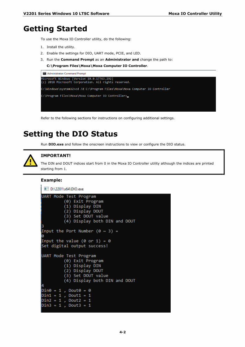
Setting the DIO Status Run DIO.exe and follow the onscreen instructions to view or configure the DIO status.
IMPORTANT!
The DIN and DOUT indices start from 0 in the Moxa IO Controller utility although the indices are printed starting from 1.
Example:

V2201 Series Windows 10 LTSC Software Moxa IO Controller Utility
4-3
Setting the UART Mode Run UartMode.exe and follow the onscreen instructions to view or configure the UART mode.
IMPORTANT!
The UART index starts from 0 in the Moxa IO Controller utility although it is printed starting with 1.
Example:

V2201 Series Windows 10 LTSC Software Moxa IO Controller Utility
4-4
Setting the PCIE Status Run PwrExample.exe and follow the onscreen instructions to view or configure the PCIE status.
IMPORTANT!
The PCIE index starts from 0 in the Moxa IO Controller utility although it is printed starting with 1.
Example:

V2201 Series Windows 10 LTSC Software Moxa IO Controller Utility
4-5
Setting the LED Status Run LEDexample.exe and follow the onscreen instructions to view or configure the LED status.
IMPORTANT!
The LED index starts from 0 in the Moxa IO Controller utility although it is printed starting with 1.
Example:

5 5. Moxa Serial Interface Utility
This chapter describes how to use Serial Interface utility to set the UART mode.
The following topics are covered in this chapter:
Setting the UART Mode

V2201 Series Windows 10 LTSC Software Moxa Serial Interface Utility
5-2
Setting the UART Mode 1. Install the Moxa Serial Interface utility.
After the installation is complete, you should be able to see the mxSerialInterface utility in the programs menu by clicking on the Start button.
2. Run the mxSerialInterface utility.
3. Select the target COM port and UART mode and click OK to save the settings.

6 6. IO Control API
The following topics are covered in this chapter:
mxgpio
mxdgio_open
mxgpio_get_data
mxgpio_set_data
mxgpio_close
mxdgio
mxdgio_open
mxdgio_get_input_signal
mxdgio_get_output_signal
mxdgio_set_output_signal_low
mxdgio_set_output_signal_high
mxdgio_close
mxsp
mxsp_open
mxsp_get_interface
mxsp_set_interface
mxsp_close
mxwdg
mxwdg_open
mxwdg_refresh
mxwdg_close

V2201 Series Windows 10 LTSC Software IO Control API
6-2
mxgpio The mxgpio library operates on the general-purpose I/Os (GPIO) and consists of the following functions:
• mxgpio_open
• mxgpio_get_data
• mxgpio_set_data
• mxgpio_close
Requirements Name Items Header mxgpio.h
Library mxgpio.lib
DLL mxgpio.dll
mxdgio_open Syntax HANDLE mxgpio_open(void);
Description Open a GPIO handle
Parameters None
Return Value The status of the GPIO interface (1 or 0)
mxgpio_get_data Syntax int mxgpio_get_data(HANDLE fd, unsigned int port_no);
Description Get the GPIO input status.
Parameters fd Handle of the GPIO device port A GPIO port index; starts from 0.
Return Value The status of GPIO port; 0 is low, 1 is high.
mxgpio_set_data Syntax int mxgpio_set_data(HANDLE fd, unsigned int port_no, int data);
Description Set the GPIO status to high.
Parameters fd Handle of the GPIO device port A GPIO port index; starts from 0.
Return Value Returns 0 on success, otherwise the function has failed
mxgpio_close Syntax void mxgpio_close(HANDLE fd);
Description Close the GPIO device.
Parameters fd Handle of the GPIO device
Return Value None

V2201 Series Windows 10 LTSC Software IO Control API
6-3
mxdgio The mxdgio library operates on the digital I/Os and consists of the following functions:
• mxdgio_open
• mxdgio_get_input_signal
• mxdgio_get_output_signal
• mxdgio_set_output_signal_low
• mxdgio_set_output_signal_high
• mxdgio_close
Requirements Name Items
Header mxdgio.h
Library mxdgio.lib
DLL mxdgio.dll
mxdgio_open Syntax HANDLE mxdgio_open();
Description Opens the digital I/O device
Parameters None
Return Value The handle of the digital I/O
mxdgio_get_input_signal Syntax int mxdgio_get_input_signal(HANDLE fd, int port);
Description Gets the digital input status
Parameters fd Handle of the digital I/O device port A digital input port index; starts from 0
Return Value The status of the digital input port; 0 is low, 1 is high
mxdgio_get_output_signal Syntax int mxdgio_get_output_signal(HANDLE fd, int port);
Description Gets the digital output status
Parameters fd Handle of the digital I/O device port A digital output port index; starts from 0
Return Value The status of the digital output port; 0 is low, 1 is high
mxdgio_set_output_signal_low Syntax int mxdgio_set_output_signal_low(HANDLE fd, unsigned int port);
Description Sets the digital output status to low
Parameters fd Handle of the digital I/O device port A digital output port index; starts from 0
Return Value Returns 0 on success; otherwise, the function has failed

V2201 Series Windows 10 LTSC Software IO Control API
6-4
mxdgio_set_output_signal_high Syntax int mxdgio_set_output_signal_high(HANDLE fd, unsigned int port);
Description Sets the digital output status to high
Parameters fd Handle of the digital I/O device port A port index of a digital output port; starts from 0
Return Value Returns 0 on success; otherwise the function has failed
mxdgio_close Syntax void mxdgio_close(HANDLE fd);
Description Closes the digital I/O device
Parameters fd Handle of the digital I/O device
Return Value None
mxsp The mxsp library operates on the UART (serial) interface and consists of the following functions:
• mxsp_open
• mxsp_get_interface
• mxsp_set_interface
• mxsp_close
Requirements Name Items
Header mxsp.h
Library mxsp.lib
DLL mxsp.dll
mxsp_open Syntax HANDLE mxsp_open();;
Description Initializes the serial interface
Parameters None
Return Value Returns the serial interface handle.
mxsp_get_interface Syntax int mxsp_get_interface(HANDLE fd, int port_index);
Description Gets the serial interface mode
Parameters fd The serial interface handle port_index A serial interface port index; starts from 0.
Return Value 0: RS-232 mode 1: RS-485-2W mode 2: RS-422 mode 3: RS-485-4W mode

V2201 Series Windows 10 LTSC Software IO Control API
6-5
mxsp_set_interface Syntax int mxsp_set_interface(HANDLE fd, int port_index, int
port_interface);
Description Sets the serial interface mode
Parameters fd The serial interface handle port_index A port index of the serial port; starts from 0 port_interface 0: RS-232 mode
1: RS-485-2W mode 2: RS-422 mode 3: RS-485-4W mode
Return Value Return 0 on success, otherwise the function has failed.
mxsp_close Syntax void mxsp_close();
Description Close the serial interface.
Parameters None
Return Value None
mxwdg The mxwdg library operates on the watchdog timer and consists of the following functions:
• mxwdg_open
• mxwdg_refresh
• mxwdg_close
Requirements Name Items
Header mxwdg.h
Library mxwdg.lib
DLL mxwdg.dll
mxwdg_open Syntax PVOID mxwdg_open(unsigned long time);
Description Open the watchdog timer
Parameters time Initial refresh time in second.
Return Value Return Pointer to Watchdog handle. Return -1 on failure.
mxwdg_refresh Syntax int mxwdg_refresh(PVOID fd);
Description Refresh the watchdog timer.
Parameters fd The handle.
Return Value Returns 0 on success, otherwise the function has failed.

V2201 Series Windows 10 LTSC Software IO Control API
6-6
mxwdg_close Syntax void mxwdg_close(PVOID fd);
Description Closes the watchdog timer.
Parameters fd The handle.
Return Value This function does not return a value.

7 7. System Recovery
This chapter describes the Windows Recovery setup process.
The following topics are covered in this chapter:
Preparing a USB device
Booting From a USB Disk
Creating a Backup Image
Restoring the System Using a Backup Image

V2201 Series Windows 10 LTSC Software System Recovery
7-2
Preparing a USB device 1. Format the USB disk for the FAT32 file system.
2. Run the tuxboot-windows-23.exe program from the \recovery folder.
3. Select Pre Downloaded and click on the browse button (…).
4. Browse to and select the ISO file from the \recovery folder.

V2201 Series Windows 10 LTSC Software System Recovery
7-3
5. Select the USB Drive type and the Drive.
6. Click OK.
The boot files will be copied to your USB device.

V2201 Series Windows 10 LTSC Software System Recovery
7-4
7. After the files are copied, click Exit to stop the program.
8. Copy the os_image directory from the \recovery folder to the *\home\partimag* folder on the USB device.
The USB disk is now ready for use in the recovery process.
Booting From a USB Disk 1. Turn on the computer and press F2 when you hear the beep sound to enter the BIOS setup menu.
2. Select Boot Manager and press Enter to continue.

V2201 Series Windows 10 LTSC Software System Recovery
7-5
3. Select EFI USB Devices and press Enter to continue to boot from the USB device.
Creating a Backup Image After you boot the system from a USB disk, you will see the Moxa System Save & Restore Utility page.
1. In the Moxa System Save & Restore Utility, select clonezilla live save disk.

V2201 Series Windows 10 LTSC Software System Recovery
7-6
2. Wait for the USB device boot process to finish.
3. Click y to continue the process.

V2201 Series Windows 10 LTSC Software System Recovery
7-7
4. Wait for the backup process to complete.
5. Select poweroff to power off the computer when the backup process is completed.

V2201 Series Windows 10 LTSC Software System Recovery
7-8
Restoring the System Using a Backup Image After you boot the system from a USB disk, you will see the Moxa System Save & Restore Utility page.
1. In the Moxa System Save & Restore Utility, select clonezilla live restore disk.
2. Wait for the USB boot process to complete.

V2201 Series Windows 10 LTSC Software System Recovery
7-9
3. Wait for the system restore process to complete.
4. Select poweroff to power off the computer after the backup process is complete.
5. Remove the USB device after the computer has been powered off.