V-22 Osprey VTOL - Horizon Hobby · 2019-06-10 · V-22 Osprey VTOL EN 2 As the user of this...
20
Instruction Manual Bedienungsanleitung Manuel d’utilisation Manuale di Istruzioni V-22 Osprey VTOL 68-251018-34821
Transcript of V-22 Osprey VTOL - Horizon Hobby · 2019-06-10 · V-22 Osprey VTOL EN 2 As the user of this...
Instruction ManualBedienungsanleitungManuel d’utilisation Manuale di Istruzioni
V-22 Osprey VTOL
68-251018-34821
V-22 Osprey VTOL
EN
2
As the user of this product, you are solely responsible for operating in a manner that does not endanger yourself and others or result in damage to the product or the property of others.
• Always keep a safe distance in all directions around your model to avoid collisions or injury. This model is controlled by a radio signal subject to interference from many sources outside your control. Interference can cause momentary loss of control.
• Always operate your model in open spaces away from full-size vehicles, traffi c and people.
• Always carefully follow the directions and warnings for this and any optional support equipment (chargers, rechargeable battery packs, etc.).
• Always keep all chemicals, small parts and anything electrical out of the reach of children.
• Always avoid water exposure to all equipment not specifi cally designed and protected for this purpose. Moisture causes damage to electronics.
• Never place any portion of the model in your mouth as it could cause serious injury or even death.
• Never operate your model with low transmitter batteries.• Always keep aircraft in sight and under control.• Always use fully charged batteries.• Always keep transmitter powered on while aircraft is powered.• Always remove batteries before disassembly.• Always keep moving parts clean.• Always keep parts dry.• Always let parts cool after use before touching.• Always remove batteries after use.• Always ensure failsafe is properly set before fl ying.• Never operate aircraft with damaged wiring.• Never touch moving parts.
NOTICE
All instructions, warranties and other collateral documents are subject to change at the sole discretion of Horizon Hobby, LLC. For up-to-date product literature, visit horizonhobby.com or towerhobbies.com and click on the support or resources tab for this product.
Meaning of Special Language:
The following terms are used throughout the product literature to indicate various levels of potential harm when operating this product:WARNING: Procedures, which if not properly followed, create the probability of property damage, collateral damage, and serious injury OR create a high probability of superfi cial injury.
CAUTION: Procedures, which if not properly followed, create the probability of physical property damage AND a possibility of serious injury.
NOTICE: Procedures, which if not properly followed, create a possibility of physical property damage AND little or no possibility of injury.
WARNING: Read the ENTIRE instruction manual to become familiar with the features of the product before operating. Failure to operate the product correctly can result in damage to the product, personal property and cause serious injury.
This is a sophisticated hobby product. It must be operated with caution and common sense and requires some basic mechanical ability. Failure to operate this Product in a safe and responsible manner could result in injury or damage to the product or other property. This product is not intended for use by children without direct adult supervision. Do not use with incompatible components or alter this product in any way outside of the instructions provided by Horizon Hobby, LLC. This manual contains instructions for safety, operation and maintenance. It is essential to read and follow all the instructions and warnings in the manual, prior to assembly, setup or use, in order to operate correctly and avoid damage or serious injury.
Safety Precautions and Warnings
14+AGE RECOMMENDATION:Not for children under 14 years. This is not a toy.
WARNING AGAINST COUNTERFEIT PRODUCTS: If you ever need to replace your Spektrum receiver found in a Horizon Hobby product, always purchase from Horizon Hobby, LLC or a Horizon Hobby
authorized dealer to ensure authentic high-quality Spektrum product. Horizon Hobby, LLC disclaims all support and warranty with regards, but not limited to, compatibility and performance of counterfeit products or products claiming compatibility with DSM or Spektrum technology.
EN
3BNF Basic/PNP
Prefl ight .............................................................................................4Transmitter Setup .............................................................................4Transmitter and Receiver Binding .......................................................4Battery Installation and ESC Arming ...................................................5Center of Gravity (CG) .......................................................................5Flight Control Direction Test ..............................................................6Check the Nacelle Movement .............................................................6Flight Conditions ................................................................................7Linkage Settings and Flight Trimming ................................................8Understanding the Primary Flight Controls .........................................8Flying Your Aircraft ...........................................................................10Post Flight .......................................................................................11PNP Receiver Selection and Installation ...........................................11Motor Service ..................................................................................12Receiver, Servo, and ESC Connection Diagram .................................13FPV System Installation (Optional) ....................................................13Troubleshooting Guide .....................................................................14AMA National Model Aircraft Safety Code .........................................15Limited Warranty .............................................................................16Contact Information .........................................................................17FCC Information ..............................................................................17IC Information ..................................................................................17Compliance Information for the European Union ...............................17Exploded View .................................................................................62Replacement Parts ...........................................................................63Optional Parts ..................................................................................63
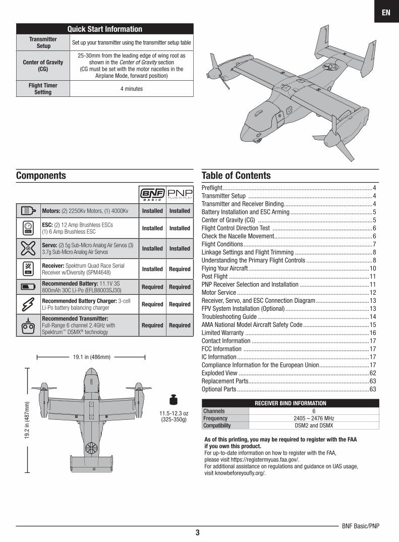
Quick Start Information
Transmitter Setup
Set up your transmitter using the transmitter setup table
Center of Gravity (CG)
25-30mm from the leading edge of wing root as shown in the Center of Gravity section
(CG must be set with the motor nacelles in the Airplane Mode, forward position)
Flight TimerSetting
4 minutes
Table of Contents
11.5-12.3 oz (325-350g)
19.2
in (4
87m
m)
19.1 in (486mm)
Components
Motors: (2) 2250Kv Motors, (1) 4000Kv Installed Installed
ESC: (2) 12 Amp Brushless ESCs(1) 6 Amp Brushless ESC
Installed Installed
Servo: (2) 5g Sub-Micro Analog Air Servos (3) 3.7g Sub-Micro Analog Air Servos
Installed Installed
Receiver: Spektrum Quad Race Serial Receiver w/Diversity (SPM4648)
Installed Required
Recommended Battery: 11.1V 3S 800mAh 30C Li-Po (EFLB8003SJ30)
Required Required
Recommended Battery Charger: 3-cell Li-Po battery balancing charger
Required Required
Recommended Transmitter: Full-Range 6 channel 2.4GHz with Spektrum™ DSMX® technology
Required Required
As of this printing, you may be required to register with the FAAif you own this product. For up-to-date information on how to register with the FAA,please visit https://registermyuas.faa.gov/.For additional assistance on regulations and guidance on UAS usage,visit knowbeforeyoufl y.org/.
RECEIVER BIND INFORMATION
Channels 6Frequency 2405 – 2476 MHzCompatibility DSM2 and DSMX
V-22 Osprey VTOL
EN
4
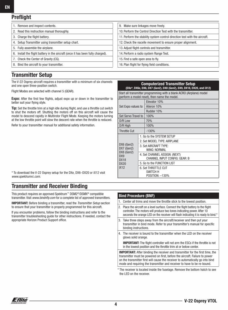
Prefl ight
1. Remove and inspect contents.
2. Read this instruction manual thoroughly.
3. Charge the fl ight battery.
4. Setup Transmitter using transmitter setup chart.
5. Fully assemble the airplane.
6. Install the fl ight battery in the aircraft (once it has been fully charged).
7. Check the Center of Gravity (CG).
8. Bind the aircraft to your transmitter.
9. Make sure linkages move freely.
10. Perform the Control Direction Test with the transmitter.
11. Perform the stability system control direction test with the aircraft.
12. Check the nacelle movement to ensure proper alignment.
13. Adjust fl ight controls and transmitter.
14. Perform a radio system Range Test.
15. Find a safe open area to fl y.
16. Plan fl ight for fl ying fi eld conditions.
Transmitter Setup The V-22 Osprey aircraft requires a transmitter with a minimum of six channels and one open three-position switch.
Flight Modes are selected with channel 5 (GEAR).
Expo: After the fi rst few fl ights, adjust expo up or down in the transmitter to better suit your fl ying style.
Tip: Set the throttle trim at a high idle during fl ight, and use a throttle cut switch to shut the motors off. Shutting the motors off on this aircraft will cause the model to descend rapidly in Multirotor Flight Mode. Keeping the motors turning at the low throttle point will slow the descent rate when the throttle is reduced.
Refer to your transmitter manual for additional safety information.
This product requires an approved Spektrum™ DSM2®/DSMX® compatible transmitter. Visit www.bindnfl y.com for a complete list of approved transmitters.
IMPORTANT: Before binding a transmitter, read the Transmitter Setup section to ensure that your transmitter is properly programmed for this aircraft.
If you encounter problems, follow the binding instructions and refer to the transmitter troubleshooting guide for other instructions. If needed, contact the appropriate Horizon Product Support offi ce.
Transmitter and Receiver Binding
Bind Procedure (BNF)
1. Center all trims and move the throttle stick to the lowest position.
2. Place the aircraft on a level surface. Connect the fl ight battery to the fl ight controller. The motors will produce two tones indicating power. After 10 seconds the orange LED on the receiver will fl ash indicating it is ready to bind.*
3. Take three steps away from the aircraft/receiver and then put your transmitter in bind mode. Refer to your transmitter’s manual for specifi c binding instructions.
4. The receiver is bound to the transmitter when the LED on the receiver glows solid orange.
IMPORTANT: The fl ight controller will not arm the ESCs if the throttle is not in the lowest position and the throttle trim at or below center.
IMPORTANT: After binding the receiver and transmitter for the fi rst time, the transmitter must be powered on fi rst, before the aircraft. Failure to power on the transmitter fi rst will cause the receiver to automatically go into bind mode and requiring the transmitter and receiver to have to be re-bound.
* The receiver is located inside the fuselage. Remove the bottom hatch to see the LED on the receiver.
Computerized Transmitter Setup(DXe*, DX6e, DX6, DX7 (Gen2), DX8 (Gen2), DX9, DX18, DX20, and iX12)
Start all transmitter programming with a blank ACRO (Airplane) model (perform a model reset), then name the model.
Set Expo values toElevator 10%Aileron 10%Rudder 10%
Set Servo Travel to 100% D/R Low 70%D/R High 100%
Throttle Cut -130%
DX6 (Gen2)DX7 (Gen2)DX8 (Gen2)DX9DX18DX20iX12
1. Go to the SYSTEM SETUP2. Set MODEL TYPE: AIRPLANE 3. Set AIRCRAFT TYPE: WING: NORMAL4. Set CHANNEL ASSIGN: (NEXT) CHANNEL INPUT CONFIG: GEAR: B5. Go to the FUNCTION LIST6. Set THROTTLE CUT SWITCH H POSITION: –130%
* To download the V-22 Osprey setup for the DXe, DX6–DX20 or iX12 visit www.spektrumrc.com.
EN
5BNF Basic/PNP
Battery Installation and ESC Arming
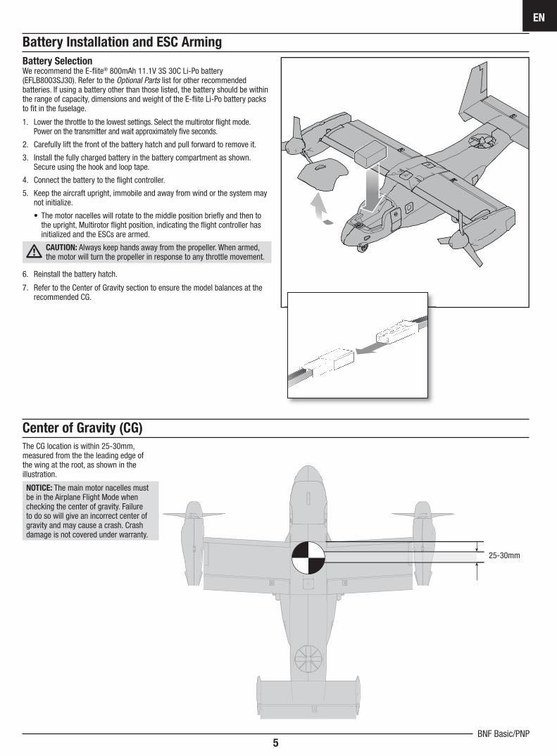
Battery SelectionWe recommend the E-fl ite® 800mAh 11.1V 3S 30C Li-Po battery (EFLB8003SJ30). Refer to the Optional Parts list for other recommended batteries. If using a battery other than those listed, the battery should be within the range of capacity, dimensions and weight of the E-fl ite Li-Po battery packs to fi t in the fuselage.
1. Lower the throttle to the lowest settings. Select the multirotor fl ight mode. Power on the transmitter and wait approximately fi ve seconds.
2. Carefully lift the front of the battery hatch and pull forward to remove it.
3. Install the fully charged battery in the battery compartment as shown. Secure using the hook and loop tape.
4. Connect the battery to the fl ight controller.
5. Keep the aircraft upright, immobile and away from wind or the system may not initialize.
• The motor nacelles will rotate to the middle position briefl y and then to the upright, Multirotor fl ight position, indicating the fl ight controller has initialized and the ESCs are armed.
CAUTION: Always keep hands away from the propeller. When armed, the motor will turn the propeller in response to any throttle movement.
6. Reinstall the battery hatch.
7. Refer to the Center of Gravity section to ensure the model balances at the recommended CG.
Center of Gravity (CG)
The CG location is within 25-30mm, measured from the the leading edge of the wing at the root, as shown in the illustration.
NOTICE: The main motor nacelles must be in the Airplane Flight Mode when checking the center of gravity. Failure to do so will give an incorrect center of gravity and may cause a crash. Crash damage is not covered under warranty.
25-30mm
V-22 Osprey VTOL
EN
6
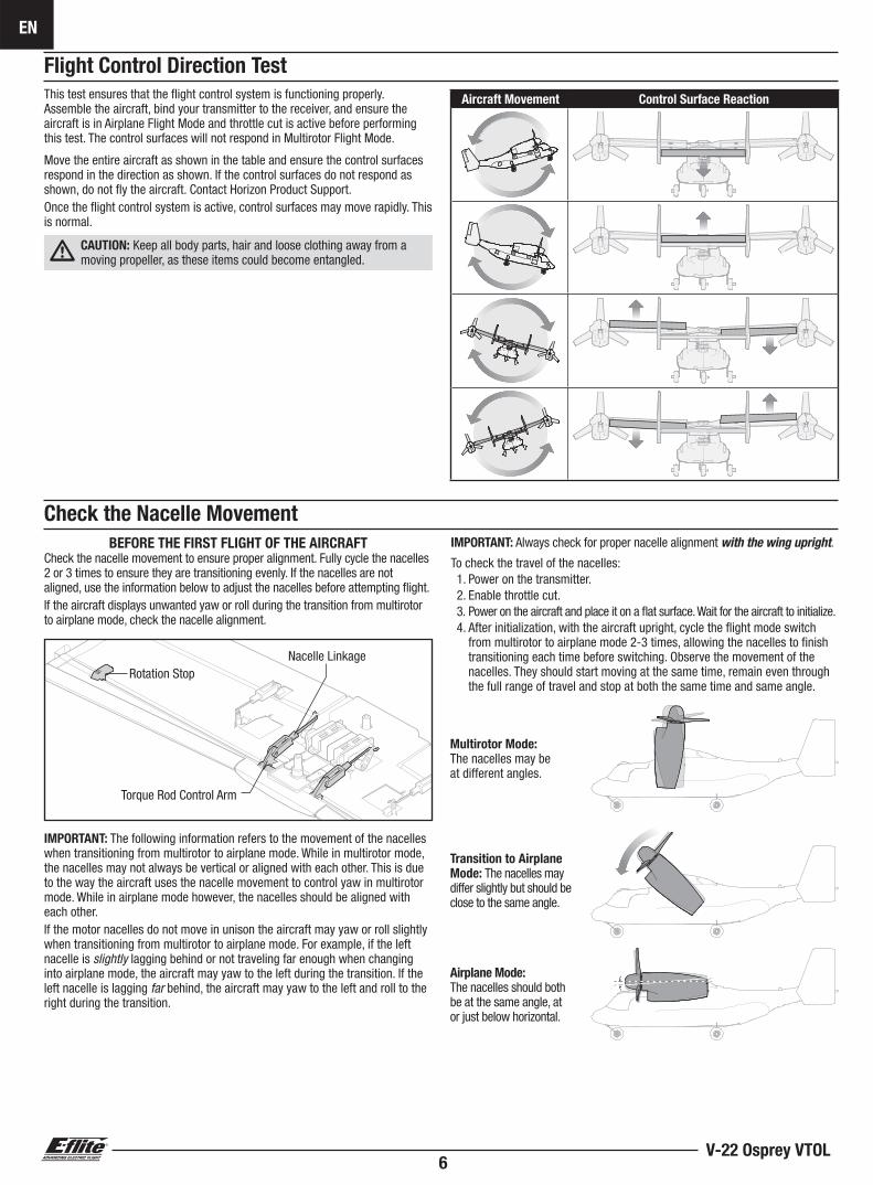
IMPORTANT: The following information refers to the movement of the nacelles when transitioning from multirotor to airplane mode. While in multirotor mode, the nacelles may not always be vertical or aligned with each other. This is due to the way the aircraft uses the nacelle movement to control yaw in multirotor mode. While in airplane mode however, the nacelles should be aligned with each other.If the motor nacelles do not move in unison the aircraft may yaw or roll slightly when transitioning from multirotor to airplane mode. For example, if the left nacelle is slightly lagging behind or not traveling far enough when changing into airplane mode, the aircraft may yaw to the left during the transition. If the left nacelle is lagging far behind, the aircraft may yaw to the left and roll to the right during the transition.
Torque Rod Control Arm
Rotation StopNacelle Linkage
BEFORE THE FIRST FLIGHT OF THE AIRCRAFTCheck the nacelle movement to ensure proper alignment. Fully cycle the nacelles 2 or 3 times to ensure they are transitioning evenly. If the nacelles are not aligned, use the information below to adjust the nacelles before attempting fl ight.If the aircraft displays unwanted yaw or roll during the transition from multirotor to airplane mode, check the nacelle alignment.
Multirotor Mode:The nacelles may be at different angles.
Transition to Airplane Mode: The nacelles may differ slightly but should be close to the same angle.
Airplane Mode:The nacelles should both be at the same angle, at or just below horizontal.
IMPORTANT: Always check for proper nacelle alignment with the wing upright.
To check the travel of the nacelles:1. Power on the transmitter.2. Enable throttle cut.3. Power on the aircraft and place it on a fl at surface. Wait for the aircraft to initialize.4. After initialization, with the aircraft upright, cycle the fl ight mode switch
from multirotor to airplane mode 2-3 times, allowing the nacelles to fi nish transitioning each time before switching. Observe the movement of the nacelles. They should start moving at the same time, remain even through the full range of travel and stop at both the same time and same angle.
Flight Control Direction Test
This test ensures that the fl ight control system is functioning properly. Assemble the aircraft, bind your transmitter to the receiver, and ensure the aircraft is in Airplane Flight Mode and throttle cut is active before performing this test. The control surfaces will not respond in Multirotor Flight Mode.
Move the entire aircraft as shown in the table and ensure the control surfaces respond in the direction as shown. If the control surfaces do not respond as shown, do not fl y the aircraft. Contact Horizon Product Support.Once the fl ight control system is active, control surfaces may move rapidly. This is normal.
CAUTION: Keep all body parts, hair and loose clothing away from a moving propeller, as these items could become entangled.
Aircraft Movement Control Surface Reaction
Check the Nacelle Movement
EN
7BNF Basic/PNP
39-40mm
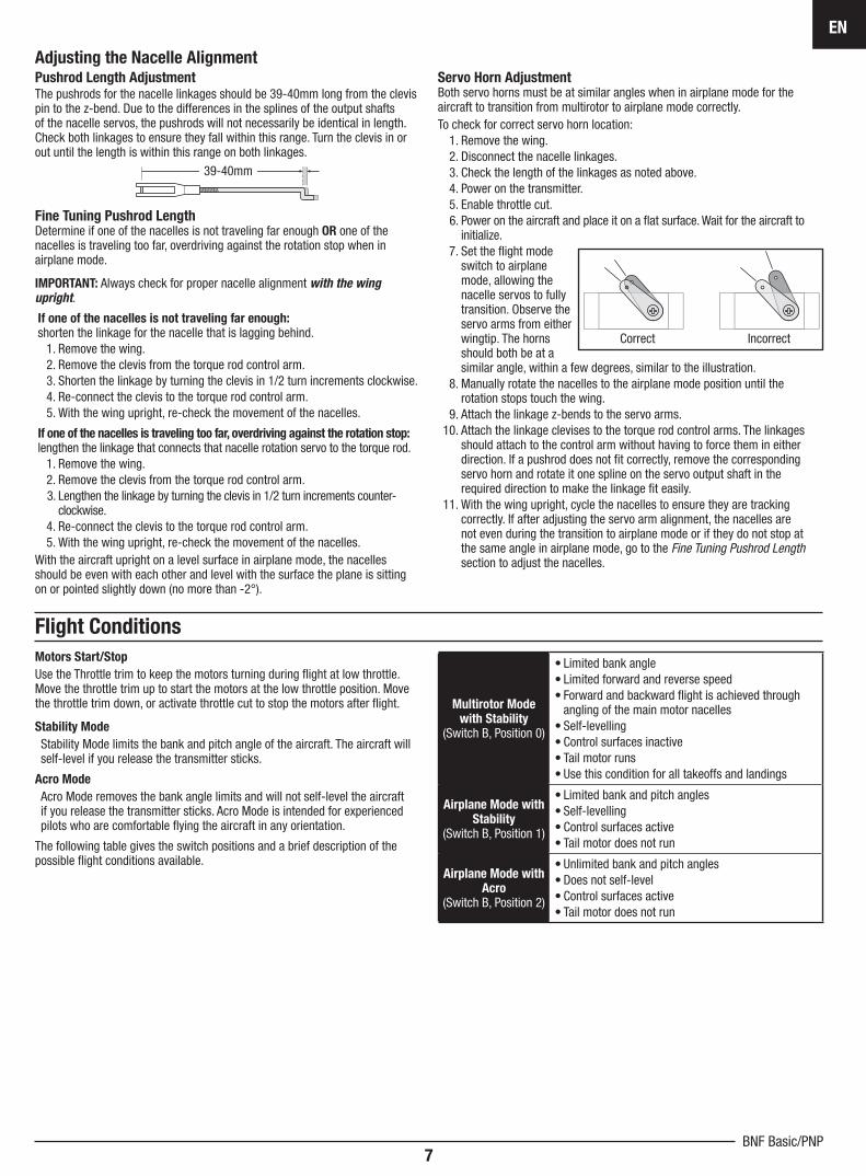
Adjusting the Nacelle AlignmentPushrod Length AdjustmentThe pushrods for the nacelle linkages should be 39-40mm long from the clevis pin to the z-bend. Due to the differences in the splines of the output shafts of the nacelle servos, the pushrods will not necessarily be identical in length. Check both linkages to ensure they fall within this range. Turn the clevis in or out until the length is within this range on both linkages.
Fine Tuning Pushrod LengthDetermine if one of the nacelles is not traveling far enough OR one of the nacelles is traveling too far, overdriving against the rotation stop when in airplane mode.
IMPORTANT: Always check for proper nacelle alignment with the wing upright.
If one of the nacelles is not traveling far enough:shorten the linkage for the nacelle that is lagging behind.
1. Remove the wing.2. Remove the clevis from the torque rod control arm.3. Shorten the linkage by turning the clevis in 1/2 turn increments clockwise.4. Re-connect the clevis to the torque rod control arm.5. With the wing upright, re-check the movement of the nacelles.
If one of the nacelles is traveling too far, overdriving against the rotation stop:lengthen the linkage that connects that nacelle rotation servo to the torque rod.
1. Remove the wing.2. Remove the clevis from the torque rod control arm.3. Lengthen the linkage by turning the clevis in 1/2 turn increments counter-
clockwise.4. Re-connect the clevis to the torque rod control arm.5. With the wing upright, re-check the movement of the nacelles.
With the aircraft upright on a level surface in airplane mode, the nacelles should be even with each other and level with the surface the plane is sitting on or pointed slightly down (no more than -2°).
Servo Horn AdjustmentBoth servo horns must be at similar angles when in airplane mode for the aircraft to transition from multirotor to airplane mode correctly.To check for correct servo horn location:
1. Remove the wing.2. Disconnect the nacelle linkages.3. Check the length of the linkages as noted above.4. Power on the transmitter.5. Enable throttle cut.6. Power on the aircraft and place it on a fl at surface. Wait for the aircraft to
initialize.7. Set the fl ight mode
switch to airplane mode, allowing the nacelle servos to fully transition. Observe the servo arms from either wingtip. The horns should both be at a similar angle, within a few degrees, similar to the illustration.
8. Manually rotate the nacelles to the airplane mode position until the rotation stops touch the wing.
9. Attach the linkage z-bends to the servo arms.10. Attach the linkage clevises to the torque rod control arms. The linkages
should attach to the control arm without having to force them in either direction. If a pushrod does not fi t correctly, remove the corresponding servo horn and rotate it one spline on the servo output shaft in the required direction to make the linkage fi t easily.
11. With the wing upright, cycle the nacelles to ensure they are tracking correctly. If after adjusting the servo arm alignment, the nacelles are not even during the transition to airplane mode or if they do not stop at the same angle in airplane mode, go to the Fine Tuning Pushrod Lengthsection to adjust the nacelles.
Correct Incorrect
Flight Conditions
Multirotor Mode with Stability
(Switch B, Position 0)
• Limited bank angle• Limited forward and reverse speed• Forward and backward fl ight is achieved through
angling of the main motor nacelles• Self-levelling• Control surfaces inactive• Tail motor runs• Use this condition for all takeoffs and landings
Airplane Mode with Stability
(Switch B, Position 1)
• Limited bank and pitch angles• Self-levelling• Control surfaces active• Tail motor does not run
Airplane Mode with Acro
(Switch B, Position 2)
• Unlimited bank and pitch angles• Does not self-level• Control surfaces active• Tail motor does not run
Motors Start/Stop
Use the Throttle trim to keep the motors turning during fl ight at low throttle. Move the throttle trim up to start the motors at the low throttle position. Move the throttle trim down, or activate throttle cut to stop the motors after fl ight.
Stability Mode
Stability Mode limits the bank and pitch angle of the aircraft. The aircraft will self-level if you release the transmitter sticks.
Acro Mode
Acro Mode removes the bank angle limits and will not self-level the aircraft if you release the transmitter sticks. Acro Mode is intended for experienced pilots who are comfortable fl ying the aircraft in any orientation.
The following table gives the switch positions and a brief description of the possible fl ight conditions available.
V-22 Osprey VTOL
EN
8
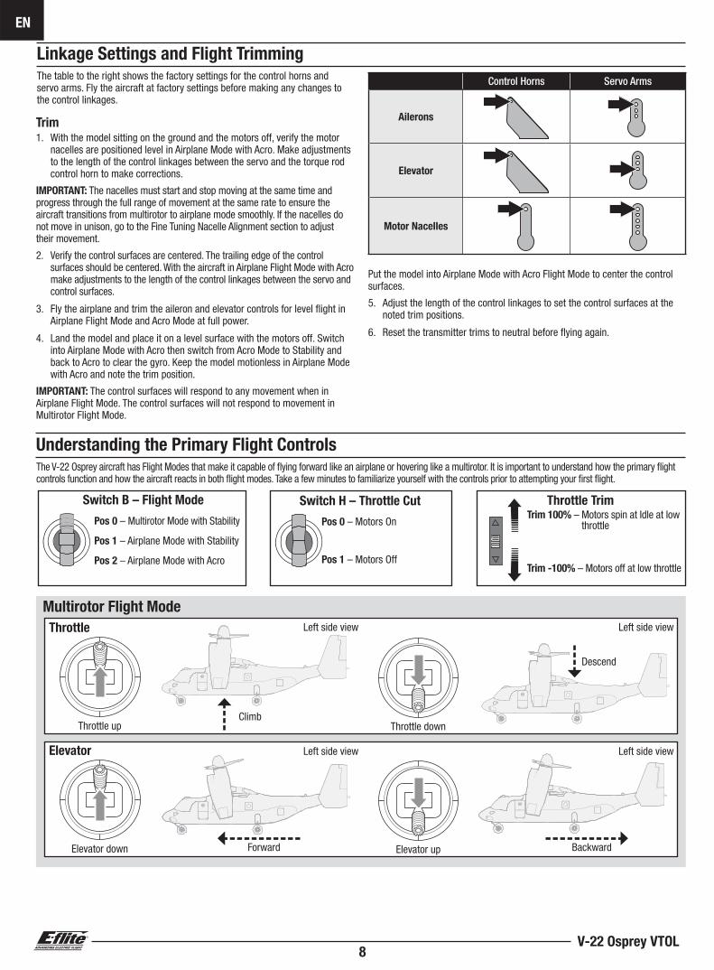
Linkage Settings and Flight TrimmingThe table to the right shows the factory settings for the control horns andservo arms. Fly the aircraft at factory settings before making any changes to the control linkages.
Trim1. With the model sitting on the ground and the motors off, verify the motor
nacelles are positioned level in Airplane Mode with Acro. Make adjustments to the length of the control linkages between the servo and the torque rod control horn to make corrections.
IMPORTANT: The nacelles must start and stop moving at the same time and progress through the full range of movement at the same rate to ensure the aircraft transitions from multirotor to airplane mode smoothly. If the nacelles do not move in unison, go to the Fine Tuning Nacelle Alignment section to adjust their movement.
2. Verify the control surfaces are centered. The trailing edge of the control surfaces should be centered. With the aircraft in Airplane Flight Mode with Acro make adjustments to the length of the control linkages between the servo and control surfaces.
3. Fly the airplane and trim the aileron and elevator controls for level fl ight in Airplane Flight Mode and Acro Mode at full power.
4. Land the model and place it on a level surface with the motors off. Switch into Airplane Mode with Acro then switch from Acro Mode to Stability and back to Acro to clear the gyro. Keep the model motionless in Airplane Mode with Acro and note the trim position.
IMPORTANT: The control surfaces will respond to any movement when in Airplane Flight Mode. The control surfaces will not respond to movement in Multirotor Flight Mode.
Put the model into Airplane Mode with Acro Flight Mode to center the control surfaces.
5. Adjust the length of the control linkages to set the control surfaces at the noted trim positions.
6. Reset the transmitter trims to neutral before fl ying again.
Understanding the Primary Flight ControlsThe V-22 Osprey aircraft has Flight Modes that make it capable of fl ying forward like an airplane or hovering like a multirotor. It is important to understand how the primary fl ight controls function and how the aircraft reacts in both fl ight modes. Take a few minutes to familiarize yourself with the controls prior to attempting your fi rst fl ight.
Throttle
Elevator
Multirotor Flight Mode
Throttle up
Elevator down
Throttle down
Elevator up
Climb
Left side view
Left side view
Left side view
Left side view
Forward Backward
Descend
Switch H – Throttle Cut Switch B – Flight Mode Throttle Trim
Pos 0 – Multirotor Mode with Stability
Pos 1 – Airplane Mode with Stability
Pos 2 – Airplane Mode with Acro
Pos 0 – Motors On
Pos 1 – Motors Off
Trim 100% – Motors spin at Idle at low throttle
Trim -100% – Motors off at low throttle
Multirotor Flight Mode
Control Horns Servo Arms
Ailerons
Elevator
Motor Nacelles
EN
9BNF Basic/PNP
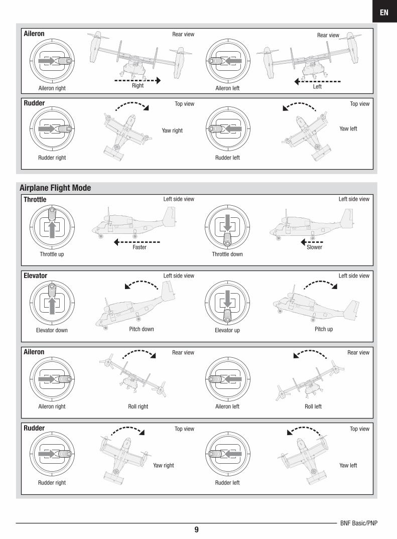
Throttle
Airplane Flight Mode
Throttle up Throttle down
Left side view Left side view
Faster Slower
Aileron
Rudder
Aileron right
Rudder right
Aileron left
Rudder left
Rear view
Top view
Rear view
Top view
LeftRight
Yaw right Yaw left
Elevator
Aileron
Rudder
Elevator down
Aileron right
Rudder right
Elevator up
Aileron left
Rudder left
Left side view
Rear view
Top view
Left side view
Rear view
Top view
Pitch down
Roll leftRoll right
Pitch up
Yaw right Yaw left
V-22 Osprey VTOL
EN
10
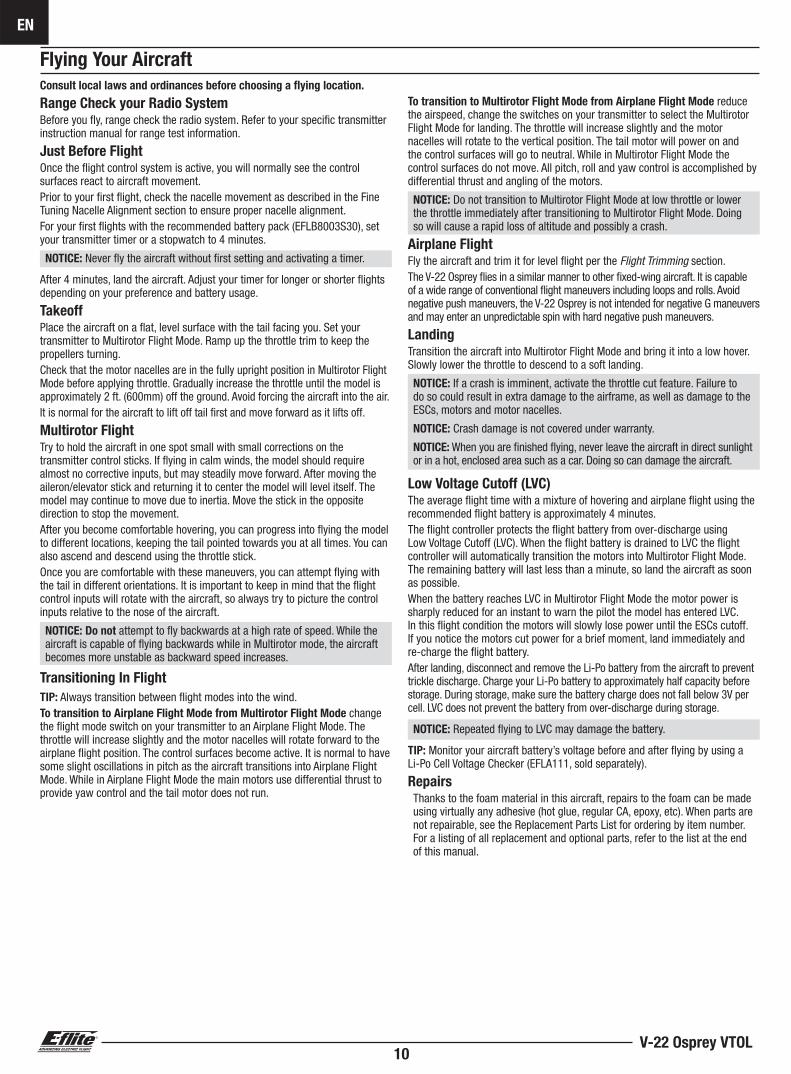
Flying Your Aircraft
Consult local laws and ordinances before choosing a fl ying location.
Range Check your Radio SystemBefore you fl y, range check the radio system. Refer to your specifi c transmitter instruction manual for range test information.
Just Before FlightOnce the fl ight control system is active, you will normally see the control surfaces react to aircraft movement.Prior to your fi rst fl ight, check the nacelle movement as described in the Fine Tuning Nacelle Alignment section to ensure proper nacelle alignment.For your fi rst fl ights with the recommended battery pack (EFLB8003S30), set your transmitter timer or a stopwatch to 4 minutes.
NOTICE: Never fl y the aircraft without fi rst setting and activating a timer.
After 4 minutes, land the aircraft. Adjust your timer for longer or shorter fl ights depending on your preference and battery usage.
TakeoffPlace the aircraft on a fl at, level surface with the tail facing you. Set your transmitter to Multirotor Flight Mode. Ramp up the throttle trim to keep the propellers turning.Check that the motor nacelles are in the fully upright position in Multirotor Flight Mode before applying throttle. Gradually increase the throttle until the model is approximately 2 ft. (600mm) off the ground. Avoid forcing the aircraft into the air.It is normal for the aircraft to lift off tail fi rst and move forward as it lifts off.
Multirotor FlightTry to hold the aircraft in one spot small with small corrections on the transmitter control sticks. If fl ying in calm winds, the model should require almost no corrective inputs, but may steadily move forward. After moving the aileron/elevator stick and returning it to center the model will level itself. The model may continue to move due to inertia. Move the stick in the opposite direction to stop the movement.After you become comfortable hovering, you can progress into fl ying the model to different locations, keeping the tail pointed towards you at all times. You can also ascend and descend using the throttle stick.Once you are comfortable with these maneuvers, you can attempt fl ying with the tail in different orientations. It is important to keep in mind that the fl ight control inputs will rotate with the aircraft, so always try to picture the control inputs relative to the nose of the aircraft.
NOTICE: Do not attempt to fl y backwards at a high rate of speed. While the aircraft is capable of fl ying backwards while in Multirotor mode, the aircraft becomes more unstable as backward speed increases.
Transitioning In Flight
TIP: Always transition between fl ight modes into the wind.To transition to Airplane Flight Mode from Multirotor Flight Mode change the fl ight mode switch on your transmitter to an Airplane Flight Mode. The throttle will increase slightly and the motor nacelles will rotate forward to the airplane fl ight position. The control surfaces become active. It is normal to have some slight oscillations in pitch as the aircraft transitions into Airplane Flight Mode. While in Airplane Flight Mode the main motors use differential thrust to provide yaw control and the tail motor does not run.
To transition to Multirotor Flight Mode from Airplane Flight Mode reduce the airspeed, change the switches on your transmitter to select the Multirotor Flight Mode for landing. The throttle will increase slightly and the motor nacelles will rotate to the vertical position. The tail motor will power on and the control surfaces will go to neutral. While in Multirotor Flight Mode the control surfaces do not move. All pitch, roll and yaw control is accomplished by differential thrust and angling of the motors.
NOTICE: Do not transition to Multirotor Flight Mode at low throttle or lower the throttle immediately after transitioning to Multirotor Flight Mode. Doing so will cause a rapid loss of altitude and possibly a crash.
Airplane FlightFly the aircraft and trim it for level fl ight per the Flight Trimming section.The V-22 Osprey fl ies in a similar manner to other fi xed-wing aircraft. It is capable of a wide range of conventional fl ight maneuvers including loops and rolls. Avoid negative push maneuvers, the V-22 Osprey is not intended for negative G maneuvers and may enter an unpredictable spin with hard negative push maneuvers.
Landing Transition the aircraft into Multirotor Flight Mode and bring it into a low hover. Slowly lower the throttle to descend to a soft landing.
NOTICE: If a crash is imminent, activate the throttle cut feature. Failure to do so could result in extra damage to the airframe, as well as damage to the ESCs, motors and motor nacelles.
NOTICE: Crash damage is not covered under warranty.
NOTICE: When you are fi nished fl ying, never leave the aircraft in direct sunlight or in a hot, enclosed area such as a car. Doing so can damage the aircraft.
Low Voltage Cutoff (LVC)The average fl ight time with a mixture of hovering and airplane fl ight using the recommended fl ight battery is approximately 4 minutes.The fl ight controller protects the fl ight battery from over-discharge using Low Voltage Cutoff (LVC). When the fl ight battery is drained to LVC the fl ight controller will automatically transition the motors into Multirotor Flight Mode. The remaining battery will last less than a minute, so land the aircraft as soon as possible.When the battery reaches LVC in Multirotor Flight Mode the motor power is sharply reduced for an instant to warn the pilot the model has entered LVC. In this fl ight condition the motors will slowly lose power until the ESCs cutoff. If you notice the motors cut power for a brief moment, land immediately and re-charge the fl ight battery.After landing, disconnect and remove the Li-Po battery from the aircraft to prevent trickle discharge. Charge your Li-Po battery to approximately half capacity before storage. During storage, make sure the battery charge does not fall below 3V per cell. LVC does not prevent the battery from over-discharge during storage.
NOTICE: Repeated fl ying to LVC may damage the battery.
TIP: Monitor your aircraft battery’s voltage before and after fl ying by using a Li-Po Cell Voltage Checker (EFLA111, sold separately).
RepairsThanks to the foam material in this aircraft, repairs to the foam can be made using virtually any adhesive (hot glue, regular CA, epoxy, etc). When parts are not repairable, see the Replacement Parts List for ordering by item number. For a listing of all replacement and optional parts, refer to the list at the end of this manual.
EN
11BNF Basic/PNP
Post Flight
1. Disconnect the fl ight battery from the fl ight controller(Required for safety and battery life).
2. Power OFF the transmitter.3. Remove the fl ight battery from the aircraft.4. Recharge the fl ight battery.
5. Repair or replace all damaged parts.6. Store the fl ight battery apart from the aircraft and monitor the battery charge.7. Make note of the fl ight conditions and fl ight plan results, planning for
future fl ights.
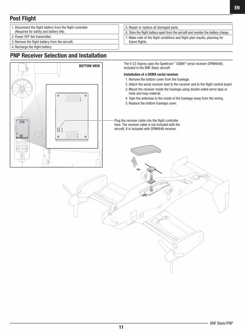
PNP Receiver Selection and Installation
The V-22 Osprey uses the Spektrum™ DSMX® serial receiver (SPM4648), included in the BNF-Basic aircraft.
Installation of a DSMX serial receiver
1. Remove the bottom cover from the fuselage. 2. Attach the serial receiver lead to the receiver and to the fl ight control board.3. Mount the receiver inside the fuselage using double-sided servo tape or
hook and loop material.4. Tape the antennas to the inside of the fuselage away from the wiring.5. Replace the bottom fuselage cover.
BOTTOM VIEW
Plug the receiver cable into the fl ight controller here. The receiver cable is not included with the aircraft, it is included with SPM4648 receiver.
S+–
S+–
S+–
S+–
S+–
S+–
S+–
S+–
S+–
V-22 Osprey VTOL
EN
12
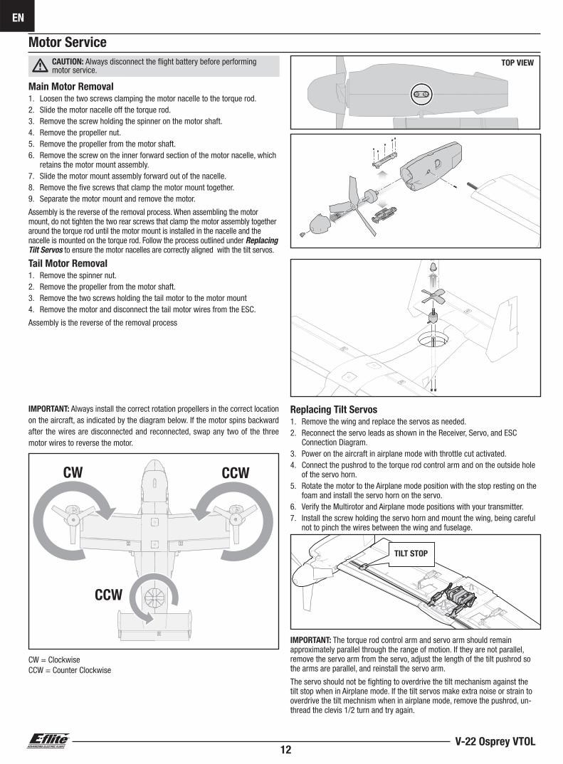
CAUTION: Always disconnect the fl ight battery before performing motor service.
Main Motor Removal1. Loosen the two screws clamping the motor nacelle to the torque rod.2. Slide the motor nacelle off the torque rod.3. Remove the screw holding the spinner on the motor shaft.4. Remove the propeller nut.5. Remove the propeller from the motor shaft.6. Remove the screw on the inner forward section of the motor nacelle, which
retains the motor mount assembly.7. Slide the motor mount assembly forward out of the nacelle. 8. Remove the fi ve screws that clamp the motor mount together.9. Separate the motor mount and remove the motor.
Assembly is the reverse of the removal process. When assembling the motor mount, do not tighten the two rear screws that clamp the motor assembly together around the torque rod until the motor mount is installed in the nacelle and the nacelle is mounted on the torque rod. Follow the process outlined under Replacing Tilt Servos to ensure the motor nacelles are correctly aligned with the tilt servos.
Motor Service
Tail Motor Removal1. Remove the spinner nut. 2. Remove the propeller from the motor shaft.3. Remove the two screws holding the tail motor to the motor mount4. Remove the motor and disconnect the tail motor wires from the ESC.
Assembly is the reverse of the removal process
Replacing Tilt Servos1. Remove the wing and replace the servos as needed.2. Reconnect the servo leads as shown in the Receiver, Servo, and ESC
Connection Diagram.3. Power on the aircraft in airplane mode with throttle cut activated.4. Connect the pushrod to the torque rod control arm and on the outside hole
of the servo horn.5. Rotate the motor to the Airplane mode position with the stop resting on the
foam and install the servo horn on the servo. 6. Verify the Multirotor and Airplane mode positions with your transmitter. 7. Install the screw holding the servo horn and mount the wing, being careful
not to pinch the wires between the wing and fuselage.
IMPORTANT: The torque rod control arm and servo arm should remain approximately parallel through the range of motion. If they are not parallel, remove the servo arm from the servo, adjust the length of the tilt pushrod so the arms are parallel, and reinstall the servo arm.
The servo should not be fi ghting to overdrive the tilt mechanism against the tilt stop when in Airplane mode. If the tilt servos make extra noise or strain to overdrive the tilt mechnism when in airplane mode, remove the pushrod, un-thread the clevis 1/2 turn and try again.
TOP VIEW
IMPORTANT: Always install the correct rotation propellers in the correct location on the aircraft, as indicated by the diagram below. If the motor spins backward after the wires are disconnected and reconnected, swap any two of the three motor wires to reverse the motor.
CW
CCW
CCW
CW = ClockwiseCCW = Counter Clockwise
TILT STOP
EN
13BNF Basic/PNP
S+–
S+–
S+–
S+–
S+–
S+–
S+–
S+–
S+–
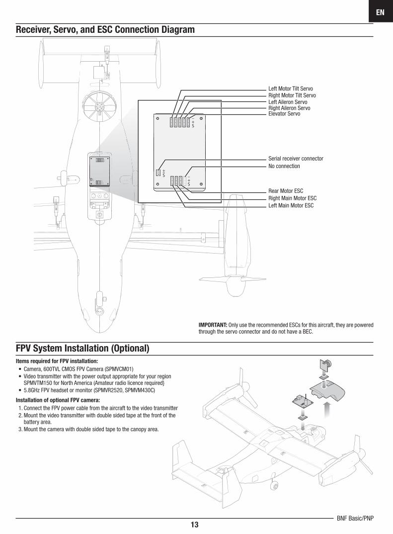
Left Aileron ServoRight Aileron Servo
Left Motor Tilt ServoRight Motor Tilt Servo
Elevator Servo
Serial receiver connectorNo connection
Rear Motor ESCRight Main Motor ESCLeft Main Motor ESC
Receiver, Servo, and ESC Connection Diagram
IMPORTANT: Only use the recommended ESCs for this aircraft, they are powered through the servo connector and do not have a BEC.
FPV System Installation (Optional)
Items required for FPV installation:
• Camera, 600TVL CMOS FPV Camera (SPMVCM01)• Video transmitter with the power output appropriate for your region
SPMVTM150 for North America (Amateur radio licence required}• 5.8GHz FPV headset or monitor (SPMVR2520, SPMVM430C)
Installation of optional FPV camera:
1. Connect the FPV power cable from the aircraft to the video transmitter2. Mount the video transmitter with double sided tape at the front of the
battery area.3. Mount the camera with double sided tape to the canopy area.
V-22 Osprey VTOL
EN
14
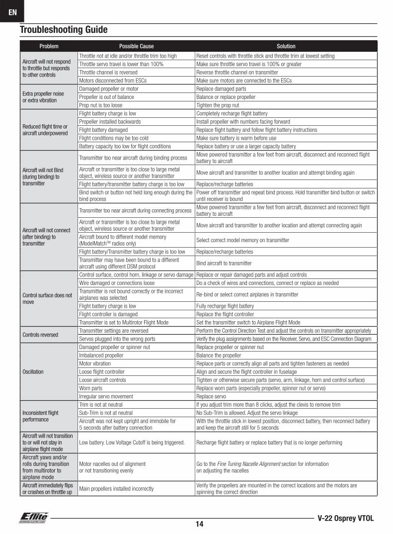
Problem Possible Cause Solution
Aircraft will not respond to throttle but respondsto other controls
Throttle not at idle and/or throttle trim too high Reset controls with throttle stick and throttle trim at lowest setting
Throttle servo travel is lower than 100% Make sure throttle servo travel is 100% or greater
Throttle channel is reversed Reverse throttle channel on transmitter
Motors disconnected from ESCs Make sure motors are connected to the ESCs
Extra propeller noiseor extra vibration
Damaged propeller or motor Replace damaged parts
Propeller is out of balance Balance or replace propeller
Prop nut is too loose Tighten the prop nut
Reduced fl ight time or aircraft underpowered
Flight battery charge is low Completely recharge fl ight battery
Propeller installed backwards Install propeller with numbers facing forward
Flight battery damaged Replace fl ight battery and follow fl ight battery instructions
Flight conditions may be too cold Make sure battery is warm before use
Battery capacity too low for flight conditions Replace battery or use a larger capacity battery
Aircraft will not Bind (during binding) to transmitter
Transmitter too near aircraft during binding processMove powered transmitter a few feet from aircraft, disconnect and reconnect fl ight battery to aircraft
Aircraft or transmitter is too close to large metal object, wireless source or another transmitter
Move aircraft and transmitter to another location and attempt binding again
Flight battery/transmitter battery charge is too low Replace/recharge batteries
Bind switch or button not held long enough during the bind process
Power off transmitter and repeat bind process. Hold transmitter bind button or switch until receiver is bound
Aircraft will not connect (after binding) to transmitter
Transmitter too near aircraft during connecting processMove powered transmitter a few feet from aircraft, disconnect and reconnect fl ight battery to aircraft
Aircraft or transmitter is too close to large metal object, wireless source or another transmitter
Move aircraft and transmitter to another location and attempt connecting again
Aircraft bound to different model memory (ModelMatchTM radios only)
Select correct model memory on transmitter
Flight battery/Transmitter battery charge is too low Replace/recharge batteries
Transmitter may have been bound to a different aircraft using different DSM protocol
Bind aircraft to transmitter
Control surface does not move
Control surface, control horn, linkage or servo damage Replace or repair damaged parts and adjust controls
Wire damaged or connections loose Do a check of wires and connections, connect or replace as needed
Transmitter is not bound correctly or the incorrect airplanes was selected
Re-bind or select correct airplanes in transmitter
Flight battery charge is low Fully recharge fl ight battery
Flight controller is damaged Replace the fl ight controller
Transmitter is set to Multirotor Flight Mode Set the transmitter switch to Airplane Flight Mode
Controls reversedTransmitter settings are reversed Perform the Control Direction Test and adjust the controls on transmitter appropriately
Servos plugged into the wrong ports Verify the plug assignments based on the Receiver, Servo, and ESC Connection Diagram
Oscillation
Damaged propeller or spinner nut Replace propeller or spinner nut
Imbalanced propeller Balance the propeller
Motor vibration Replace parts or correctly align all parts and tighten fasteners as needed
Loose fl ight controller Align and secure the fl ight controller in fuselage
Loose aircraft controls Tighten or otherwise secure parts (servo, arm, linkage, horn and control surface)
Worn parts Replace worn parts (especially propeller, spinner nut or servo)
Irregular servo movement Replace servo
Inconsistent fl ight performance
Trim is not at neutral If you adjust trim more than 8 clicks, adjust the clevis to remove trim
Sub-Trim is not at neutral No Sub-Trim is allowed. Adjust the servo linkage
Aircraft was not kept upright and immobile for 5 seconds after battery connection
With the throttle stick in lowest position, disconnect battery, then reconnect battery and keep the aircraft still for 5 seconds
Aircraft will not transition to or will not stay in airplane flight mode
Low battery. Low Voltage Cutoff is being triggered. Recharge fl ight battery or replace battery that is no longer performing
Aircraft yaws and/or rolls during transition from multirotor to airplane mode
Motor nacelles out of alignmentor not transitioning evenly
Go to the Fine Tuning Nacelle Alignment section for informationon adjusting the nacelles
Aircraft immediately flips or crashes on throttle up Main propellers installed incorrectly
Verify the propellers are mounted in the correct locations and the motors are spinning the correct direction
Troubleshooting Guide
EN
15BNF Basic/PNP
Effective January 1, 2014
A. GENERAL
A model aircraft is a non-human-carrying aircraft capable of sustained fl ight in the atmosphere. It may not exceed limitations of this code and is intended exclusively for sport, recreation, education and/or competition. All model fl ights must be conducted in accordance with this safety code and any additional rules specifi c to the fl ying site.
1. Model aircraft will not be fl own:(a) In a careless or reckless manner.(b) At a location where model aircraft activities are prohibited.
2. M odel aircraft pilots will:(a) Yield the right of way to all man carrying aircraft.(b) See and avoid all aircraft and a spotter must be used when appropriate.
(AMA Document #540-D.)(c) Not fl y higher than approximately 400 feet above ground level within
three (3) miles of an airport, without notifying the airport operator.(d) Not interfere with operations and traffi c patterns at any airport, heliport
or seaplane base except where there is a mixed use agreement.(e) Not exceed a takeoff weight, including fuel, of 55 pounds unless in
compliance with the AMA Large Model Aircraft program.(AMA Document 520-A.)
(f) Ensure the aircraft is identifi ed with the name and address or AMA number of the owner on the inside or affi xed to the outside of the model aircraft. (This does not apply to model aircraft fl own indoors).
(g) Not operate aircraft with metal-blade propellers or with gaseous boosts except for helicopters operated under the provisions of AMA Document #555.
(h) Not operate model aircraft while under the infl uence of alcohol or while using any drug which could adversely affect the pilot’s ability to safely control the model.
(i) Not operate model aircraft carrying pyrotechnic devices which explode or burn, or any device which propels a projectile or drops any object that creates a hazard to persons or property.
Exceptions:• Free Flight fuses or devices that burn producing smoke and are
securely attached to the model aircraft during fl ight.• Rocket motors (using solid propellant) up to a G-series size may be
used provided they remain attached to the model during fl ight. Model rockets may be fl own in accordance with the National Model Rocketry Safety Code but may not be launched from model aircraft.
• Offi cially designated AMA Air Show Teams (AST) are authorized to use devices and practices as defi ned within the Team AMA Program Document (AMA Document #718).
(j) Not operate a turbine-powered aircraft, unless in compliance with the AMA turbine regulations. (AMA Document #510-A).
3. Model aircraft will not be fl own in AMA sanctioned events, air shows or model demonstrations unless:(a) The aircraft, control system and pilot skills have successfully demonstrated
all maneuvers intended or anticipated prior to the specifi c event.(b) An inexperienced pilot is assisted by an experienced pilot.
4. When and where required by rule, helmets must be properly worn and fastened. They must be OSHA, DOT, ANSI, SNELL or NOCSAE approved or comply with comparable standards.
B. RADIO CONTROL
1. All pilots shall avoid fl ying directly over unprotected people, vessels, vehicles or structures and shall avoid endangerment of life and property of others.
2. A successful radio equipment ground-range check in accordance with manufacturer’s recommendations will be completed before the fi rst fl ight of a new or repaired model aircraft.
3. At all fl ying sites a safety line(s) must be established in front of which all fl ying takes place (AMA Document #706.)(a) Only personnel associated with fl ying the model aircraft are allowed at
or in front of the safety line.(b) At air shows or demonstrations, a straight safety line must be established.(c) An area away from the safety line must be maintained for spectators.(d) Intentional fl ying behind the safety line is prohibited.
4. RC model aircraft must use the radio-control frequencies currently allowed by the Federal Communications Commission (FCC). Only individuals properly licensed by the FCC are authorized to operate equipment on Amateur Band frequencies.
5. RC model aircraft will not operate within three (3) miles of any pre-existing fl ying site without a frequency-management agreement(AMA Documents #922 and #923.)
6. With the exception of events fl own under offi cial AMA Competition Regulations, excluding takeoff and landing, no powered model may be fl own outdoors closer than 25 feet to any individual, except for the pilot and the pilot’s helper(s) located at the fl ight line.
7. Under no circumstances may a pilot or other person touch a model aircraft in fl ight while it is still under power, except to divert it from striking an individual.
8. RC night fl ying requires a lighting system providing the pilot with a clear view of the model’s attitude and orientation at all times. Hand-held illumination systems are inadequate for night fl ying operations.
9. The pilot of a RC model aircraft shall:(a) Maintain control during the entire fl ight, maintaining visual contact without
enhancement other than by corrective lenses prescribed for the pilot.(b) Fly using the assistance of a camera or First-Person View (FPV) only in
accordance with the procedures outlined in AMA Document #550.(c) Fly using the assistance of autopilot or stabilization system only in
accordance with the procedures outlined in AMA Document #560.
Please see your local or regional modeling association’s guidelines for proper, safe operation of your model aircraft.
AMA National Model Aircraft Safety Code
V-22 Osprey VTOL
EN
16
What this Warranty CoversHorizon Hobby, LLC, (Horizon) warrants to the original purchaser that the product purchased (the “Product”) will be free from defects in materials and workmanship at the date of purchase.
What is Not CoveredThis warranty is not transferable and does not cover (i) cosmetic damage, (ii) damage due to acts of God, accident, misuse, abuse, negligence, commercial use, or due to improper use, installation, operation or maintenance, (iii) modifi cation of or to any part of the Product, (iv) attempted service by anyone other than a Horizon Hobby authorized service center, (v) Product not purchased from an authorized Horizon dealer, or (vi) Product not compliant with applicable technical regulations, or (vii) use that violates any applicable laws, rules, or regulations.
OTHER THAN THE EXPRESS WARRANTY ABOVE, HORIZON MAKES NO OTHER WARRANTY OR REPRESENTATION, AND HEREBY DISCLAIMS ANY AND ALL IMPLIED WARRANTIES, INCLUDING, WITHOUT LIMITATION, THE IMPLIED WARRANTIES OF NON-INFRINGEMENT, MERCHANTABILITY AND FITNESS FOR A PARTICULAR PURPOSE. THE PURCHASER ACKNOWLEDGES THAT THEY ALONE HAVE DETERMINED THAT THE PRODUCT WILL SUITABLY MEET THE REQUIREMENTS OF THE PURCHASER’S INTENDED USE.
Purchaser’s RemedyHorizon’s sole obligation and purchaser’s sole and exclusive remedy shall be that Horizon will, at its option, either (i) service, or (ii) replace, any Product determined by Horizon to be defective. Horizon reserves the right to inspect any and all Product(s) involved in a warranty claim. Service or replacement decisions are at the sole discretion of Horizon. Proof of purchase is required for all warranty claims. SERVICE OR REPLACEMENT AS PROVIDED UNDER THIS WARRANTY IS THE PURCHASER’S SOLE AND EXCLUSIVE REMEDY.
Limitation of LiabilityHORIZON SHALL NOT BE LIABLE FOR SPECIAL, INDIRECT, INCIDENTAL OR CONSEQUENTIAL DAMAGES, LOSS OF PROFITS OR PRODUCTION OR COMMERCIAL LOSS IN ANY WAY, REGARDLESS OF WHETHER SUCH CLAIM IS BASED IN CONTRACT, WARRANTY, TORT, NEGLIGENCE, STRICT LIABILITY OR ANY OTHER THEORY OF LIABILITY, EVEN IF HORIZON HAS BEEN ADVISED OF THE POSSIBILITY OF SUCH DAMAGES. Further, in no event shall the liability of Horizon exceed the individual price of the Product on which liability is asserted. As Horizon has no control over use, setup, fi nal assembly, modifi cation or misuse, no liability shall be assumed nor accepted for any resulting damage or injury. By the act of use, setup or assembly, the user accepts all resulting liability. If you as the purchaser or user are not prepared to accept the liability associated with the use of the Product, purchaser is advised to return the Product immediately in new and unused condition to the place of purchase.
LawThese terms are governed by Illinois law (without regard to confl ict of law principals). This warranty gives you specifi c legal rights, and you may also have other rights which vary from state to state. Horizon reserves the right to change or modify this warranty at any time without notice.
WARRANTY SERVICES
Questions, Assistance, and ServicesYour local hobby store and/or place of purchase cannot provide warranty support or service. Once assembly, setup or use of the Product has been started, you must contact your local distributor or Horizon directly. This will enable Horizon to better answer your questions and service you in the event that you may need any assistance. For questions or assistance, please visit our website at www.horizonhobby.com, submit a Product Support Inquiry, or call the toll free telephone number referenced in the Warranty and Service Contact Information section to speak with a Product Support representative.
Inspection or ServicesIf this Product needs to be inspected or serviced and is compliant in the country you live and use the Product in, please use the Horizon Online Service Request submission process found on our website or call Horizon to obtain a Return Merchandise Authorization (RMA) number. Pack the Product securely using a shipping carton. Please note that original boxes may be included, but are not designed to withstand the rigors of shipping without additional protection. Ship via a carrier that provides tracking and insurance for lost or damaged parcels, as Horizon is not responsible for merchandise until it arrives and is accepted at our facility. An Online Service Request is available at http://www.horizonhobby.com/content/service-center_render-service-center. If you do not have internet access, please contact Horizon Product Support to obtain a RMA number along with instructions for submitting your product for service. When calling Horizon, you will be asked to provide your complete name, street address, email address and phone number where you can be reached during business hours. When sending product into Horizon, please include your RMA number, a list of the included items, and a brief summary of the problem. A copy of your original sales receipt must be included for warranty consideration. Be sure your name, address, and RMA number are clearly written on the outside of the shipping carton.
NOTICE: Do not ship LiPo batteries to Horizon. If you have any issue with a LiPo battery, please contact the appropriate Horizon Product Support offi ce.
Warranty Requirements For Warranty consideration, you must include your original sales receipt verifying the proof-of-purchase date. Provided warranty conditions have been met, your Product will be serviced or replaced free of charge. Service or replacement decisions are at the sole discretion of Horizon.
Non-Warranty Service
Should your service not be covered by warranty, service will be completed and payment will be required without notifi cation or estimate of the expense unless the expense exceeds 50% of the retail purchase cost. By submitting the item for service you are agreeing to payment of the service without notifi cation. Service estimates are available upon request. You must include this request with your item submitted for service. Non-warranty service estimates will be billed a minimum of ½ hour of labor. In addition you will be billed for return freight. Horizon accepts money orders and cashier’s checks, as well as Visa, MasterCard, American Express, and Discover cards. By submitting any item to Horizon for service, you are agreeing to Horizon’s Terms and Conditions found on our website http://www.horizonhobby.com/content/service-center_render-service-center.
ATTENTION: Horizon service is limited to Product compliant in the country of use and ownership. If received, a non-compliant Product will not be serviced. Further, the sender will be responsible for arranging return shipment of the un-serviced Product, through a carrier of the sender’s choice and at the sender’s expense. Horizon will hold non-compliant Product for a period of 60 days from notifi cation, after which it will be discarded.
10/15
Limited Warranty
EN
17BNF Basic/PNP
Country of
PurchaseHorizon Hobby Contact Information Address
United States of America
Horizon Service Center
(Repairs and Repair Requests)
servicecenter.horizonhobby.com/
RequestForm/
2904 Research Rd. Champaign, Illinois, 61822 USA
Horizon Product Support
(Product Technical Assistance)
877-504-0233
800-338-4639
European UnionHorizon Technischer Service [email protected] Hanskampring 9
D 22885 Barsbüttel, GermanySales: Horizon Hobby GmbH +49 (0) 4121 2655 100
Contact Information
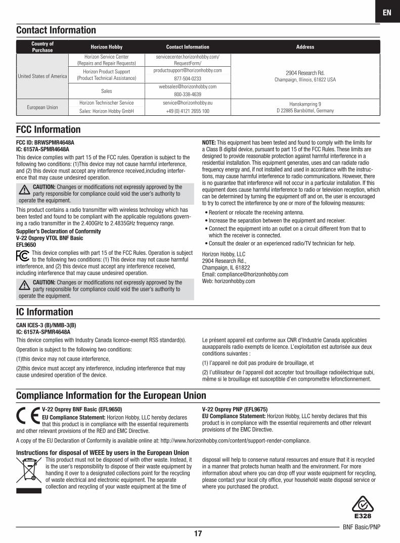
FCC ID: BRWSPMR4648AIC: 6157A-SPMR4648A
This device complies with part 15 of the FCC rules. Operation is subject to the following two conditions: (1)This device may not cause harmful interference, and (2) this device must accept any interference received,including interfer-ence that may cause undesired operation.
CAUTION: Changes or modifi cations not expressly approved by the party responsible for compliance could void the user’s authority to
operate the equipment.
This product contains a radio transmitter with wireless technology which has been tested and found to be compliant with the applicable regulations govern-ing a radio transmitter in the 2.400GHz to 2.4835GHz frequency range.Supplier’s Declaration of ConformityV-22 Osprey VTOL BNF BasicEFL9650
This device complies with part 15 of the FCC Rules. Operation is subject to the following two conditions: (1) This device may not cause harmful
interference, and (2) this device must accept any interference received, including interference that may cause undesired operation.
CAUTION: Changes or modifi cations not expressly approved by the party responsible for compliance could void the user’s authority to
operate the equipment.
NOTE: This equipment has been tested and found to comply with the limits for a Class B digital device, pursuant to part 15 of the FCC Rules. These limits are designed to provide reasonable protection against harmful interference in a residential installation. This equipment generates, uses and can radiate radio frequency energy and, if not installed and used in accordance with the instruc-tions, may cause harmful interference to radio communications. However, there is no guarantee that interference will not occur in a particular installation. If this equipment does cause harmful interference to radio or television reception, which can be determined by turning the equipment off and on, the user is encouraged to try to correct the interference by one or more of the following measures:
• Reorient or relocate the receiving antenna.• Increase the separation between the equipment and receiver.• Connect the equipment into an outlet on a circuit different from that to
which the receiver is connected.• Consult the dealer or an experienced radio/TV technician for help.
Horizon Hobby, LLC 2904 Research Rd.,Champaign, IL 61822Email: [email protected]: horizonhobby.com
Compliance Information for the European Union
FCC Information
IC Information
CAN ICES-3 (B)/NMB-3(B)IC: 6157A-SPMR4648A
This device complies with Industry Canada licence-exempt RSS standard(s).
Operation is subject to the following two conditions:
(1)this device may not cause interference,
(2)this device must accept any interference, including interference that may cause undesired operation of the device.
Le présent appareil est conforme aux CNR d’Industrie Canada applicables auxappareils radio exempts de licence. L’exploitation est autorisée aux deux conditions suivantes :
(1) l’appareil ne doit pas produire de brouillage, et
(2) l’utilisateur de l’appareil doit accepter tout brouillage radioélectrique subi, même si le brouillage est susceptible d’en compromettre lefonctionnement.
Instructions for disposal of WEEE by users in the European UnionThis product must not be disposed of with other waste. Instead, it is the user’s responsibility to dispose of their waste equipment by handing it over to a designated collections point for the recycling of waste electrical and electronic equipment. The separate collection and recycling of your waste equipment at the time of
disposal will help to conserve natural resources and ensure that it is recycled in a manner that protects human health and the environment. For more information about where you can drop off your waste equipment for recycling, please contact your local city offi ce, your household waste disposal service or where you purchased the product.
V-22 Osprey BNF Basic (EFL9650)
EU Compliance Statement: Horizon Hobby, LLC hereby declares that this product is in compliance with the essential requirements
and other relevant provisions of the RED and EMC Directive.
V-22 Osprey PNP (EFL9675)EU Compliance Statement: Horizon Hobby, LLC hereby declares that this product is in compliance with the essential requirements and other relevant provisions of the EMC Directive.
A copy of the EU Declaration of Conformity is available online at: http://www.horizonhobby.com/content/support-render-compliance.
V-22 Osprey VTOL62
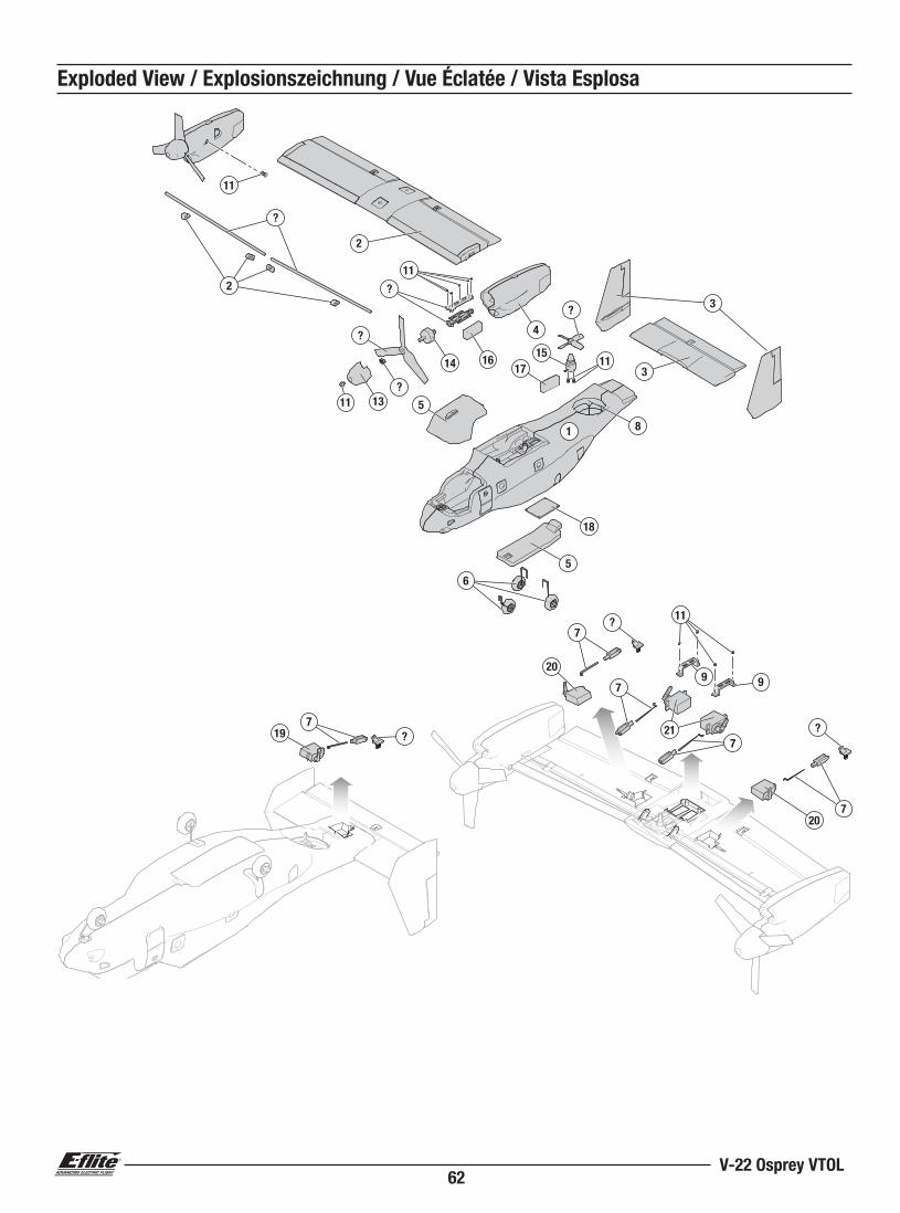
Exploded View / Explosionszeichnung / Vue Éclatée / Vista Esplosa
11
6
?
11
11
3
14 16
13
4
3
1
5
17
8
15
?
5
18
?
?
2
11
2
?
11
20
?
?
20
7
7
7
721
9 9
19 ?
7
63BNF Basic/PNP
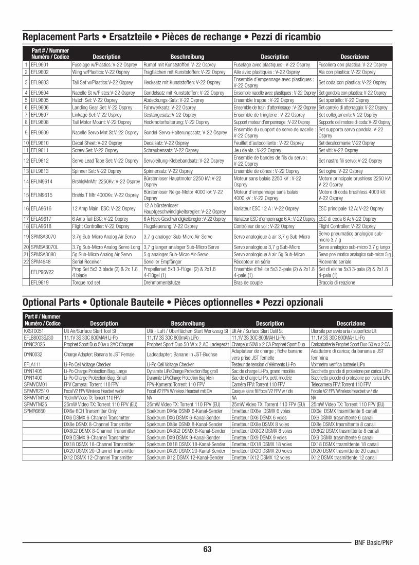
Part # / Nummer Numéro / Codice Description Beschreibung Description Descrizione
1 EFL9601 Fuselage w/Plastics: V-22 Osprey Rumpf mit Kunststoffen: V-22 Osprey Fuselage avec plastiques : V-22 Osprey Fusoliera con plastica: V-22 Osprey
2 EFL9602 Wing w/Plastics: V-22 Osprey Tragfl ächen mit Kunststoffen: V-22 Osprey Aile avec plastiques : V-22 Osprey Ala con plastica: V-22 Osprey
3 EFL9603 Tail Set w/Plastics:V-22 Osprey Hecksatz mit Kunststoffen: V-22 Osprey Ensemble d’empennage avec plastiques : V-22 Osprey
Set coda con plastica: V-22 Osprey
4 EFL9604 Nacelle St w/Plstcs:V-22 Osprey Gondelsatz mit Kunststoffen: V-22 Osprey Ensemble nacelle avec plastiques : V-22 Osprey Set gondola con plastica: V-22 Osprey
5 EFL9605 Hatch Set: V-22 Osprey Abdeckungs-Satz: V-22 Osprey Ensemble trappe : V-22 Osprey Set sportello: V-22 Osprey
6 EFL9606 Landing Gear Set: V-22 Osprey Fahrwerksatz: V-22 Osprey Ensemble de train d’atterrissage : V-22 Osprey Set carrello di atterraggio: V-22 Osprey
7 EFL9607 Linkage Set: V-22 Osprey Gestängesatz: V-22 Osprey Ensemble de tringlerie : V-22 Osprey Set collegamenti: V-22 Osprey
8 EFL9608 Tail Motor Mount: V-22 Osprey Heckmotorhalterung: V-22 Osprey Support moteur d’empennage : V-22 Osprey Supporto del motore di coda: V-22 Osprey
9 EFL9609 Nacelle Servo Mnt St:V-22 Osprey Gondel-Servo-Halterungssatz; V-22 OspreyEnsemble du support de servo de nacelle : V-22 Osprey
Set supporto servo gondola: V-22 Osprey
10 EFL9610 Decal Sheet: V-22 Osprey Decalsatz: V-22 Osprey Feuillet d’autocollants : V-22 Osprey Set decalcomanie: V-22 Osprey
11 EFL9611 Screw Set: V-22 Osprey Schraubensatz: V-22 Osprey Jeu de vis : V-22 Osprey Set viti: V-22 Osprey
12 EFL9612 Servo Lead Tape Set: V-22 Osprey Servoleitung-Klebebandsatz: V-22 OspreyEnsemble de bandes de fi ls du servo : V-22 Osprey
Set nastro fi li servo: V-22 Osprey
13 EFL9613 Spinner Set: V-22 Osprey Spinnersatz: V-22 Osprey Ensemble de cônes : V-22 Osprey Set ogiva: V-22 Osprey
14 EFLM9614 BrshlsMnMtr 2250Kv: V-22 Osprey Bürstenloser Hauptmotor 2250 kV: V-22 Osprey
Moteur sans balais 2250 kV : V-22 Osprey
Motore principale brushless 2250 kV: V-22 Osprey
15 EFLM9615 Brshls T Mtr 4000Kv: V-22 OspreyBürstenloser Neige-Motor 4000 kV: V-22 Osprey
Moteur d’empennage sans balais 4000 kV : V-22 Osprey
Motore di coda brushless 4000 kV: V-22 Osprey
16 EFLA9616 12 Amp Main ESC: V-22 Osprey 12 A bürstenloser Hauptgeschwindigkeitsregler: V-22 Osprey
Variateur ESC 12 A : V-22 Osprey ESC principale 12 A: V-22 Osprey
17 EFLA9617 6 Amp Tail ESC: V-22 Osprey 6 A Heck-Geschwindigkeitsregler: V-22 Osprey Variateur ESC d’empennage 6 A : V-22 Osprey ESC di coda 6 A: V-22 Osprey
18 EFLA9618 Flight Controller: V-22 Osprey Flugsteuerung: V-22 Osprey Contrôleur de vol : V-22 Osprey Flight Controller: V-22 Osprey
19 SPMSA3070 3.7g Sub-Micro Analog Air Servo 3,7 g analoger Sub-Micro Air-Servo Servo analogique à air 3,7 g Sub-MicroServo pneumatico analogico sub-micro 3,7 g
20 SPMSA3070L 3.7g Sub-Micro Analog Servo Long 3,7 g langer analoger Sub-Micro Servo Servo analogique 3,7 g Sub-Micro Servo analogico sub-micro 3,7 g lungo
21 SPMSA3080 5g Sub-Micro Analog Air Servo 5 g analoger Sub-Micro Air-Servo Servo analogique à air 5g Sub-Micro Servo pneumatico analogico sub-micro 5 g
22 SPM4648 Serial Receiver Serieller Empfänger Récepteur en série Ricevente seriale
EFLP96V22Prop Set 5x3 3 blade (2) & 2x 1.8 4 blade
Propellerset 5x3 3-Flügel (2) & 2x1.8 4-Flügel (1)
Ensemble d’hélice 5x3 3-pale (2) & 2x1.8 4-pale (1)
Set di eliche 5x3 3-pala (2) & 2x1.8 4-pala (1)
EFL9619 Torque rod set Drehmomentstütze Bras de couple Braccio di reazione
Part # / Nummer Numéro / Codice Description Beschreibung Description Descrizione
KXST0051 Ult Air/Surface Start Tool St Ulti - Luft / Oberfl ächen Start Werkzeug St Ult Air / Surface Start Outil St Utensile per avvio aria / superfi cie Ult
EFLB8003SJ30 11.1V 3S 30C 800MAH Li-Po 11,1V 3S 30C 800mAh LiPo 11,1V 3S 30C 800MAH Li-Po 11,1V 3S 30C 800MAH Li-Po
DYNC2025 Prophet Sport Duo 50w x 2AC Charger Prophet Sport Duo 50 W x 2 AC Ladegerät Chargeur 50W x 2 CA Prophet Sport Duo Caricabatterie Prophet Sport Duo 50 w x 2 CA
DYN0032 Charge Adapter; Banana to JST Female Ladeadapter; Banane in JST-BuchseAdaptateur de charge ; fi che banane
vers prise JST femelle
Adattatore di carica; da banana a JST
femmina
EFLA111 Li-Po Cell Voltage Checker Li-Po Cell Voltage Checker Testeur de tension d’éléments Li-Po Voltmetro verifi ca batterie LiPo
DYN1405 Li-Po Charge Protection Bag, Large Dynamite LiPoCharge Protection Bag groß Sac de charge Li-Po, grand modèle Sacchetto grande di protezione per carica LiPo
DYN1400 Li-Po Charge Protection Bag, Small Dynamite LiPoCharge Protection Bag klein Sac de charge Li-Po, petit modèle Sacchetto piccolo di protezione per carica LiPo
SPMVCM01 FPV Camera: Torrent 110 FPV FPV-Kamera: Torrent 110 FPV Caméra FPV: Torrent 110 FPV Telecamera FPV: Torrent 110 FPV
SPMVR2510 Focal V2 FPV Wireless Headset w/div Focal V2 FPV Wireless Headset mit Div Casque sans fi l Focal V2 FPV w / div Focale V2 FPV Wireless Headset w / div
SPMVTM150 150mW Video TX: Torrent 110 FPV NA NA NA
SPMVTM25 25mW Video TX: Torrent 110 FPV (EU) 25mW Video TX: Torrent 110 FPV (EU) 25mW Video TX: Torrent 110 FPV (EU) 25mW Video TX: Torrent 110 FPV (EU)
SPMR6650 DX6e 6CH Transmitter Only Spektrum DX6e DSMX 6-Kanal-Sender Emetteur DX6e DSMX 6 voies DX6e DSMX trasmittente 6 canali
DX6 DSMX 6-Channel Transmitter Spektrum DX6 DSMX 6-Kanal-Sender Emetteur DX6 DSMX 6 voies DX6 DSMX trasmittente 6 canali
DX8e DSMX 8-Channel Transmitter Spektrum DX8e DSMX 8-Kanal-Sender Emetteur DX8e DSMX 8 voies DX8e DSMX trasmittente 8 canali
DX8G2 DSMX 8-Channel Transmitter Spektrum DX8G2 DSMX 8-Kanal-Sender Emetteur DX8G2 DSMX 8 voies DX8G2 DSMX trasmittente 8 canali
DX9 DSMX 9-Channel Transmitter Spektrum DX9 DSMX 9-Kanal-Sender Emetteur DX9 DSMX 9 voies DX9 DSMX trasmittente 9 canali
DX18 DSMX 18-Channel Transmitter Spektrum DX18 DSMX 18-Kanal-Sender Emetteur DX18 DSMX 18 voies DX18 DSMX trasmittente 18 canali
DX20 DSMX 20-Channel Transmitter Spektrum DX20 DSMX 20-Kanal-Sender Emetteur DX20 DSMX 20 voies DX20 DSMX trasmittente 20 canali
iX12 DSMX 12-Channel Transmitter Spektrum iX12 DSMX 12-Kanal-Sender Emetteur iX12 DSMX 12 voies iX12 DSMX trasmittente 12 canali
Optional Parts • Optionale Bauteile • Pièces optionnelles • Pezzi opzionali
Replacement Parts • Ersatzteile • Pièces de rechange • Pezzi di ricambio

© 2019 Horizon Hobby, LLC.E-fl ite, AS3X, DSM, DSM2, DSMX, the DSMX logo, Bind-N-Fly, BNF, the BNF logo, Plug-N-Play, ModelMatch, Dynamite, EC3, Prophet, Focal and the Horizon Hobby logo
are trademarks or registered trademarks of Horizon Hobby, LLC.The Spektrum trademark is used with permission of Bachmann Industries, Inc.
Produced under license. V-22 Osprey, its distinctive logos and trade dress are jointly owned trademarks of Textron Innovations Inc. and The Boeing Company.All other trademarks, service marks and logos are property of their respective owners.
US 8,672,726. US 9,930,567.https://www.horizonhobby.com/content/e-fl ite-rc Created 02/19 58810.2EFL9650, EFL9675