V-2100G Infant Incubator
74
0123 TO THE OPERATOR AND THE PERSON IN CHARGE OF MAINTENANCE AND CARE OF THE UNIT: Read this Manual carefully before operating the unit. After reading this Manual, keep it where it is readily accessible for reference in case of need. This Manual contains description of all the functions available, including the oxygen controller and the infant's weight moni- tor. So please skip any section unrelated to your unit. Operation Manual V-2100G Infant Incubator V-2100G Infant Incubator
Transcript of V-2100G Infant Incubator

0123
TO THE OPERATOR AND THE PERSON IN CHARGEOF MAINTENANCE AND CARE OF THE UNIT:
� Read this Manual carefully before operating the unit.� After reading this Manual, keep it where it is readily accessiblefor reference in case of need.
� This Manual contains description of all the functions available,including the oxygen controller and the infant's weight moni-tor.So please skip any section unrelated to your unit.
Operation Manual
V-2100G Infant IncubatorV-2100G Infant Incubator

The name and address of our authorized representative within the community are as stated below.
15th klm National Road Athens-Lamia, 145 64 Kifissia, GreecePost Address : P.O.Box 51288, 145 10 Kifissia, Greece
Tel. : 3016294600, Fax. : 3016294610
PHARMASERVE-LILLY S.A.C.I.

- 1 -
INTRODUCTION
This Operation Manual deals with the specifications, operation and maintenance of the Atom Advanced InfantIncubator V-2100G. Atom is by no means responsible for any malfunction arising from a user ignoring the instruc-tions for operation and maintenance described in this Manual as well as for any accident attributable to repair bysomeone other than technical personnel belonging to, or authorized by, Atom.This Manual contains description of all the functions available, including the oxygen controller and the infant'sweight monitor. So please skip any section unrelated to your unit.Read this Manual carefully and familiarize yourself thoroughly with its contents before operating the unit. Keepthis Manual where it is readily accessible for reference in case of need. If any technical problem should arise,please contact your Atom distributor.
This product is shipped without being disinfected. Be sure to clean and disinfect the unit beforeusing it for the first time after purchase.
Used parts and other products past their useful lives should be disinfected and disposed of asmedical wastes.
CAUTION
INTENDED USE
The Atom Advanced Infant Incubator model V-2100G is a closed-type incubator designed to provide an optimumclinical environment for newborn and premature neonates. The Infant Incubator is also designed to offer theclinical staff optimum conditions for observation and examination, temperature stabilization and management andpost-operative care of their small patients. The Infant Incubator also incorporates the thermoregulatory ability toadjust the baby's skin temperature.Features, such as Oxygen Controller and Weight Monitor, are also optionally available.

- 2 -
SAFETY INFORMATION
Instructions to ensure safe operation of the unit are found throughout this Manual. Please read the Manualcarefully before operating the unit. Please follow the instructions in operating it.
[1] Basic Instructions
1.Follow the instructions for safe use of the unit.Follow the operating instructions described in this Manual for safe use of the unit.2.Inspect the unit on a periodical basis.Periodical inspection is needed to use the unit under optimum conditions.3.Never use the unit when faulty.If any damage or malfunction of the unit should be noticed, stop using it immediately and contact your ATOMdistributor.
[2] Definition of Warning Indication
A DANGER notice indicates an immediately hazardous situation which, if notavoided, will result in death or serious injury, serious damage to property such astotal loss of use of equipment, and a fire.
A WARNING notice indicates an indirectly (potentially) hazardous situationwhich, if not avoided, will result in death or serious injury, serious damage toproperty such as total loss of use of equipment, and a fire.
A CAUTION notice indicates a hazardous situation which, if not avoided, can re-sult in minor or moderate injury, partial damage to property, and loss of datastored in computers.
WARNING:�
Three levels of warning indication are used throughout this Manual and on the unit. They are defined asfollows.
DANGER:�
CAUTION:�

- 3 -
[3] Definition of Marks
1. Marks to indicate caution or warning
Mark 《Title》 and Indication
《General attention》
Indicates unspecified general caution or warning.
2. Marks to prohibit action
《General prohibition》
Indicates unspecified general prohibition.
《Prohibition of disassembly》
Indicates prohibition of disassembly of the unit where it may cause an electric shock or other hazards.
《Prohibition of use of fire》
Indicates prohibition of use of fire where an external use of fire may cause the unit to ignite undercertain conditions.
3. Marks to give instructions for action
《General instruction》
Indicates unspecified general action on the part of the user.
《Remove the power plug from the power outlet》
Instructs the user to remove the power plug from the power outlet in the case of malfunction orwhen thunder storm conditions threaten and lightning might occur.
《Connect a ground wire》
Instructs the user to connect the ground wire without fail where the unit is provided with a ground terminal.
4. Marks used on the unit
Caution: See the accompanying documents.
Type BF equipment is applied here.
《Caution: Hot surface》
Indicates that the surface can be dangerously hot.
Mark 《Title》 and Indication
Mark 《Title》 and Indication
Mark 《Title》 and Indication

- 4 -
Atom is by no means responsible for compensation for death, injury or damage to property if such loss
should occur due to any of the following causes.
1. Trouble or damage due to installation, maintenance or repair by someone other than technical
personnel belonging to, or authorized by, Atom.
2. Trouble or damage of Atom products caused by a product of another company other than that
supplied by Atom.
3. Trouble or damage due to modification, maintenance or repair using a part other than that speci-
fied by Atom.
4. Trouble or damage due to neglecting the operating precautions or operating instructions described
in the Operation Manual of the unit.
5. Trouble or damage due to operation under ambient conditions, including electrical requirements
and installation requirements, other than those described in the Operation Manual.
6. Trouble due to carelessness or improper modification.
7. Trouble or damage due to using secondhand equipment.
8. If an accessory device which does not meet the safety requirements of this unit is used in combina-
tion with the unit, the safety level of the resulting system may be compromised. When selecting an
accessory device, the following point should be taken into consideration.
Evidence that the safety of the accessory device was certified in accordance with a national stan-
dard conforming to IEC60601-1 and/or IEC60601-1-1.
WARRANTIES
This equipment is guaranteed by Atom Medical Corporation for a period of one year from the date of delivery to befree of any defects in both materials and workmanship when used normally for its intended purpose. Any parts ofthis equipment proving to be so defective will be repaired or replaced at no charge during the warranty period. Inthe following cases, however, actual expenses need to be paid even during the warranty period.
(1)Wear and tear of expendables.(2)Trouble and damage due to improper handling, such as dropping the unit during transport or transfer.(3)Trouble and damage due to a fire, salt, gas, extraordinary voltage, earthquake, electrical storm and
flooding, or other natural calamities.(4)Travel expenses in the case of a trip to an isolated island, a remote place, etc. for the purpose of repair.
Damage in shipment should be reported promptly to Atom accompanied by the certificate of the carrier con-cerned.All correspondence concerning the equipment should specify the model name and the serial number.
WARNING

- 5 -
WARNING
Electro-Surgical apparatus, cellular phones and other devices which generate high-frequency
noise can cause jamming to various electric equipment for medical use and thus result in
malfunction. Since portable phones and other devices are often used in medical facilities,
some measures should be taken to prevent jamming due to such devices. Portable phones
and other devices which generate high frequency should not be used near the unit during its
operation to prevent malfunction of the unit due to jamming.
[1] Precautions on Jamming
It is the user (a hospital, a doctor's office, a clinic) that is responsible for the operation, mainte-nance and care of the electric equipment for medical use. The equipment should be used only bymedical personnel.
[2] Responsibility for Care of Equipment
Do not disassemble or modify the unit. Otherwise, a fire, an electric shock or injury may
result.
[3] Prohibition of Modification
Proper periodical inspection is needed in order to maintain and use the unit under optimum condi-tions.
[4] Periodical Inspection
If any abnormal condition or trouble should occur to the unit, indicate on the unit that it is out oforder and contact immediately your Atom distributor or service engineer. See the end of thisOperation Manual for where to make contact.
If any abnormal condition or trouble should occur, do not use the unit until it has been repairedcompletely by a service engineer so as to prevent possible danger.
[5] In Case of Trouble
WARNING
CAUTION
CAUTION
CAUTION


C O N T E N T S
INTRODUCTION ...................................................................................................... 1
[1] Operating Precautions1-1. DANGER .............................................................................................. 81-2. WARNING ............................................................................................ 91-3. CAUTION ........................................................................................... 11
[2] Parts Identification2-1. Main body ................................................................................................ 122-2. Control Panel ........................................................................................... 15
[3] Preparation before Use3-1. Assembly ................................................................................................. 173-2. Where to Install the Infant Incubator ................................................... 183-3. Locking the Casters ................................................................................ 183-5. Power Outlet and Grounding ................................................................ 193-4. Adjusting the HL Stand (HL stand type) .............................................. 193-6. Power Cord and Power Switch .............................................................. 203-7. Rechargeable Battery ............................................................................. 213-8. Start-up Inspection .................................................................................. 21
[4] Incubator Air Temperature Control .....................................................224-1. Setting the Incubator Air Temperature (Manual Control) ................. 224-2. Setting the Skin Temperature (Servo Control) ................................... 27
[5] Humidity Control ........................................................................................... 32
[6] Oxygen Supply6-1. Using the Oxygen Flowmeter ............................................................... 356-2. Using the Internal Oxygen Controller (B,C type) ............................... 35
[7] Weight Monitor (C type)7-1. Calibrating the Weight Monitor ............................................................ 397-2. Setting the Weighing Mode ................................................................... 417-3. Weighing Procedure .............................................................................. 427-4. Recording the Weight ............................................................................ 447-5. Correcting the Time ............................................................................... 45
[8] Other Operation procedures8-1. Drawing out the Mattress Platform ...................................................... 468-2. Tilting the Mattress Platform ................................................................ 468-3. X-ray Cassette Tray ................................................................................. 478-4. Taking Out Cords and Tubes ................................................................ 478-5. I/O Connector ......................................................................................... 478-6. Test Switch .............................................................................................. 48
[9] Cleaning, Disinfection and Maintenance9-1. Hood ......................................................................................................... 499-2. Mattress Platform and Parts Beneath .................................................. 519-3. Others ...................................................................................................... 539-4. Humidity Chamber ................................................................................. 53
[10] Maintenance Inspection ......................................................................5510-1. Inspection before use ............................................................................ 5510-2. Three-month Inspection ....................................................................... 5610-3. Periodical Replacement Parts ............................................................... 5710-4. Replacing the Filter ............................................................................... 5810-5. Replacing the Oxygen Sensor (Unit with oxygen controller) ........... 5910-6. Inspection Check List ............................................................................ 6110-7. Life ........................................................................................................... 6210-8. Disposal .................................................................................................. 62
[11] Alarms ............................................................................................................. 63
[12] Troubleshooting ............................................................................................ 67
[13] Technical Data ............................................................................................... 68

- 8 -
[1] Operating Precautions
Please follow the operating instructions described in this Manual for safe use of the unit. The unit should beoperated only by those who have been trained and instructed properly in its operation. The unit should beoperated only for its intended use.
1-1. DANGER
Death or serious injury, damage to equipment or a fire will result if the instructions given below are not fol-lowed.
Be sure to close the front admittance panel and access ports when the unit isin use.Using the unit when the front admittance panel or an access port is left open may cause the infant tofall out of the baby compartment. Be sure to close the front admittance panel and access ports evenwhen performing phototherapy on an infant inside the incubator.
If the incubator air temperature rises when performing phototherapy, proceedwith phototherapy after placing the infant in a cot or an open incubator (infantwarmer), according to the doctor's judgment.Since growing infants release a high level of heat, the incubator air temperature may rise if you placethe infant in the incubator and perform phototherapy. Also, if you use multiple phototherapy units atthe same time, or if the room temperature is high, the incubator air temperature may rise. In thiscase, proceed with phototherapy after placing the infant in a cot or an open-type incubator, accordingto the doctor's judgment. Take sufficient care when using a cot, as it becomes difficult to watch theinfant. Also, placing an ice bag inside the incubator has the effect of decreasing the temperature.However, be sure to close the front admittance panel and access ports in this case also.
Do not leave the unit unattended when the front admittance panel or an ac-cess port is open. If the front admittance panel or an access port is left open, the infant may fall out of the baby compart-ment and even lose its life. Never leave the unit unattended when the front admittance panel or anaccess port is open.
If the front admittance panel, a snap-open access port or a hook slider shouldbe found loose or faulty in any way, stop using the unit immediately and askfor repair.The infant may fall out of the incubator.
Never place a body warmer or other possible ignition sources in or near the unit.Use of oxygen will increase a risk of explosion or a fire.
A body warmer or other devices in which fire is used or which may generate a spark may causeexplosion or a fire if used near the unit.
Do not use the unit in the presence of a flammable anesthetic gas.The unit may cause explosion or a fire if used in the presence of such a gas.
Do not use ether, alcohol or other ignitable substances.Even a small amount of ether, alcohol or other ignitable substances may cause a fire when mixedwith the oxygen in the incubator.

- 9 -
Ground the unit securely.Otherwise current leakage may cause an electric shock. To complete the ground connection, con-nect the power cord only to a 3P power outlet including a ground terminal and grounded properly.Do not operate the unit if you have any doubt about its ground connection.
Do not use near the unit any device generating high frequency.Electro-Surgical apparatus, cellular phones and other devices which generate high frequency shouldnot be used near the unit during its operation to prevent malfunction of the unit due to jamming.
Analyze arterial gas levels repeatedly when a high oxygen environment is required.It is reported to be extremely important and essential, when the infant's conditions call for a highoxygen environment, to repeatedly analyze arterial gas levels in order to maintain the oxygen con-centration in the incubator at a desired level. Follow the doctor's instructions in measuring theoxygen concentration because ignoring essential requirements may increase the risk of retinopathyof prematurity.
Do not jolt the unit or bump it against anything.The screws or fixed parts may become loose.
1-2. WARNING
Death or serious injury due to a fire or an electric shock will result if the instructions given below are notfollowed.
Be sure to follow the doctor's instructions in setting the incubator air tempera-ture or the infant's skin temperature.
Be sure to follow the doctor's instructions in setting the relative humidity in theincubator.
Be sure to follow the doctor's instructions in setting the oxygen concentrationin the incubator.
Oxygen for medical use should be used.
Be sure to bear in mind the following points during oxygen supply.●Do not place a body warmer, a flashlight, oils and fats, or flammable vaporizable matters in theincubator.
●Use pure cotton for the infant's clothing and bed sheets, etc. Do not use any material that is easilycharged with static electricity.
●Use pure cotton or fire-proofed materials for the clothing of doctors, nurses and those ambulancemen who handle this unit.
Bear in mind the following points while using oxygen supply equipment.●If oil, grease or a grease-like substance should get in contact with pressurized oxygen, a violentspontaneous ignition may occur. Do not let such substances stick to the oxygen pressure regula-tor, the oxygen cylinder valve, pipings, connections and other oxygen supply equipment.
●On a high pressure oxygen cylinder, use only a tested pressure reducing valve or pressure regu-lating valve indicated specifically for oxygen supply. Do not use such a valve for any gas otherthan air or oxygen. It is dangerous to use a valve to supply a gas other than air or oxygen and thento supply oxygen again.

- 10 -
Smoking is prohibited in the room where the unit is installed.Do not place any possible ignition sources in the room.
Avoid damaging the power cord.A damaged power cord may cause a fire or an electric shock.●Do not pinch the power cord between the unit and the wall, a shelf or the floor.●Do not place the power cord near a heating apparatus or heat it.●Do not put anything heavy on the power cord.●Always grasp the power plug with your hand to remove the power cord from the power outlet.A damaged power cord should be replaced immediately with a new one.
Use only the power cord supplied with the unit.Otherwise, a fire or an electric shock may result.
Before sanitizing the unit, ensure that the unit is electrically disconnected andthat the unit and the heater have sufficiently cooled down.
Do not touch the power plug with a wet hand.Touching the power plug with a wet hand may cause an electric shock.
Do not disassemble or modify the unit.Disassembling or modifying the unit may cause a fire, an electric shock or injury.
Do not install the unit where it will be exposed to excessive humidity, dust orsteam.Installing the unit in such a place may cause a fire or an electric shock.
The power outlet should be located near the unit to prevent accidental con-tact with a trailing power cord. Use a separate power outlet for each unit.
Do not put many loads on one power outlet.
Connect the power cord only to a 3P power outlet in order to complete theground connection.
Do not operate the unit if you have any doubt about its ground connection.
Ground peripheral electric equipment securely.
Never connect the unit to a power unit other than that specified.
The unit should be serviced only by qualified personnel.
Be sure to perform start-up inspection.Using the unit without performing start-up inspection may let a defect pass unnoticed and cause aserious accident.

- 11 -
1-3. CAUTION
Injury or damage to surrounding objects may result if the instructions given below are not followed.
Be sure to clean and disinfect the unit before using it for the first time afterpurchase.The unit is shipped without being disinfected.
Always keep the unit warm to maintain the incubator air temperature at a fixedlevel during the standby mode.
Place the infant in the incubator only when the incubator air temperature hasstabilized.
Do not twist or pull the cords by force.If any defect should be found, ask an expert for repair without attempting to repair it yourself.
Remove the power plug from the power outlet before moving the unit to an-other place or when the unit is not going to be used for a long time.Moving the unit to another place with the power plug connected to the power outlet will damage thepower cord and may cause a fire or an electric shock.
Remove the power plug from the power outlet before cleaning or disinfectingthe unit.Cleaning or disinfecting the unit with the power plug connected to the power outlet may cause anelectric shock.
Place the unit on a stable surface.Placing the unit on an unstable platform or a tilted surface will cause it to fall or drop and may hurtsomeone. Check the strength of the place where the unit is to be placed or installed.
Install the unit out of reach of small children.
In performing phototherapy to the infant in the incubator, pay special attentionto the infant's temperature and the incubator air temperature during the therapy.The infant's skin temperature and the incubator air temperature may rise due to the radiant energyof light.
Do not install the unit in direct sunshine or near a heating apparatus.
Do not expose the unit to extraordinarily high temperature or excessive hu-midity.
Do not place anything heavy on the unit.
Check the operation of the peripheral devices.If a device transmitting or receiving weak signals is installed near the unit, it may be affected by theelectromagnetic waves generated by the latter. Check the operation of peripheral devices for anyeffect before using the unit in clinical settings. Stop using the unit immediately if any trouble isdetected.

- 12 -
No. Name!0 Front admittance panel operating lever!1 Front admittance panel!2 Tube introduction slit assembly!3 Snap-open access port!4 Mattress!5 Control panel!6 Drawer!7 Caster!8 Elevating pedal
No. Nameq Sensor module (B,C type)w Sensor module (A type)e Iris access portr Relay boxt Test switchy MF railu Mattress platform tilting knobi Humidity chamber covero Front admittance panel operating knob
[2] Parts Identification
2-1. Main body
■B.C type
Note: !5 Drawer (one-layer type and two-layer type) is optionally available.
o
!1
q
e
r
i
yt
!6
!7
!8
!2
!3
!4
!5
u
!0

- 13 -
■A type
w
t

- 14 -
No. Name!9 Filter cover@0 Oxygen connecting port 1@1 Oxygen connecting port 2 (to use the inter-
nal oxygen controller)@2 Power switch@3 Weight monitor connector@4 Printer connector@5 Hood stopper@6 Mattress platform@7 X-ray cassette tray
No. Name@8 Top board packing@9 Top board#0 Fan cover#1 Fan#2 Conditioning chamber#3 Nozzle#4 Skin temperature connecting port#5 Sensor module connector (A type)#6 I/O connector (A type)
Note: @7 X-ray cassette tray is optinally available for A type
�
!9 @0 @1
@2 @5#6#5
@2 @5@4@3
@8
@9
#0
#1
#2
■ Rear
■ Inside
■ Right side (Power Unit)● A type
@2 @5
● B type
● C type
#3
#4
@6
@7
- 15 -
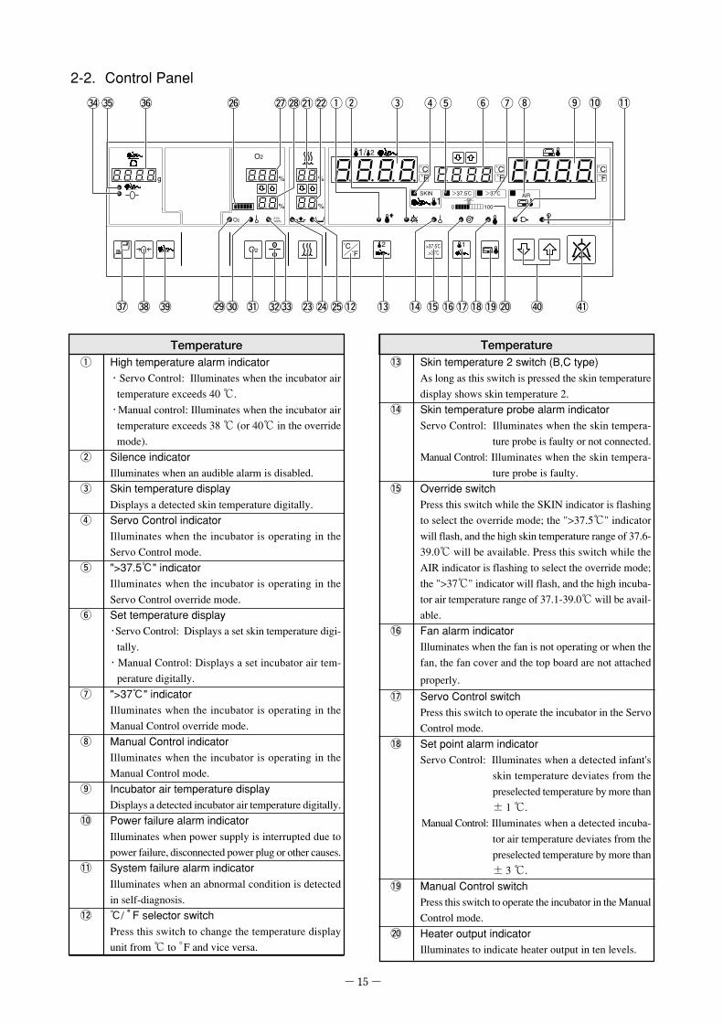
2-2. Control Panel
g
O2
%
% %
%
0 100
O2 >37.5℃�.>37℃�
O2 21%�100%
SKIN >37.5℃� >37℃� AIR
˚C˚F
˚C˚F
1/ 2
12
1
#6#4#5
!3
˚C˚F
˚C˚F
@6 @8@7 @1@2 qw e r t y u i o !0 !1
#7 #8 #9 @9#0 #1 #2#3 @3 @4 @5!2 @0!9 $0 $1!4 !6!7!8!5
Temperatureq High temperature alarm indicator
・Servo Control: Illuminates when the incubator airtemperature exceeds 40 ℃.・Manual control: Illuminates when the incubator airtemperature exceeds 38 ℃ (or 40℃ in the overridemode).
w Silence indicatorIlluminates when an audible alarm is disabled.
e Skin temperature displayDisplays a detected skin temperature digitally.
r Servo Control indicatorIlluminates when the incubator is operating in theServo Control mode.
t ">37.5℃" indicatorIlluminates when the incubator is operating in theServo Control override mode.
y Set temperature display・Servo Control: Displays a set skin temperature digi-tally.・Manual Control: Displays a set incubator air tem-perature digitally.
u ">37℃" indicatorIlluminates when the incubator is operating in theManual Control override mode.
i Manual Control indicatorIlluminates when the incubator is operating in theManual Control mode.
o Incubator air temperature displayDisplays a detected incubator air temperature digitally.
!0 Power failure alarm indicatorIlluminates when power supply is interrupted due topower failure, disconnected power plug or other causes.
!1 System failure alarm indicatorIlluminates when an abnormal condition is detectedin self-diagnosis.
!2 ℃/ °F selector switchPress this switch to change the temperature displayunit from ℃ to °F and vice versa.
Temperature!3 Skin temperature 2 switch (B,C type)
As long as this switch is pressed the skin temperaturedisplay shows skin temperature 2.
!4 Skin temperature probe alarm indicatorServo Control: Illuminates when the skin tempera-
ture probe is faulty or not connected.Manual Control: Illuminates when the skin tempera-
ture probe is faulty.!5 Override switch
Press this switch while the SKIN indicator is flashingto select the override mode; the ">37.5℃" indicatorwill flash, and the high skin temperature range of 37.6-39.0℃ will be available. Press this switch while theAIR indicator is flashing to select the override mode;the ">37℃" indicator will flash, and the high incuba-tor air temperature range of 37.1-39.0℃ will be avail-able.
!6 Fan alarm indicatorIlluminates when the fan is not operating or when thefan, the fan cover and the top board are not attached
properly.!7 Servo Control switch
Press this switch to operate the incubator in the ServoControl mode.
!8 Set point alarm indicatorServo Control: Illuminates when a detected infant's
skin temperature deviates from thepreselected temperature by more than± 1 ℃.
Manual Control: Illuminates when a detected incuba-tor air temperature deviates from thepreselected temperature by more than± 3 ℃.
!9 Manual Control switchPress this switch to operate the incubator in the ManualControl mode.
@0 Heater output indicatorIlluminates to indicate heater output in ten levels.

- 16 -
Humidity@1 Relative humidity display
Displays a detected relative humidity in the incubator digitally.@2 Set relative humidity display
Displays a set relative humidity digitally.@3 Relative humidity selector switch
Press this switch to set a relative humidity.When this switch is pressed, the relative humidity dis-play will flash, and a relative humidity can be set.Select a desired setting by pressing an appropriatesetting switch.
@4 Humidity chamber off alarm indicatorIlluminates when the humidity chamber is not posi-tioned properly or humidity chamber cover is opened.
@5 Low water level alarm indicatorFlashes and illuminates when there is little water inthe humidity chamber.
Oxygen Controller (B,C Type)
@6 Oxygen flow rate indicatorIndicates a detected oxygen flow rate in six levels.
@7 Oxygen concentration displayDisplays a detected oxygen concentration digitally.
@8 Set oxygen concentration displayDisplays a set oxygen concentration digitally.
@9 Oxygen concentration alarm indicatorFlashes when a detected oxygen concentration devi-ates from the preselected level by more than ± 3%.
#0 Oxygen sensor indicatorIlluminates when the oxygen sensor is faulty.
#1 Oxygen concentration selector switchPress this switch to set an oxygen concentration. Whenthis switch is pressed, the set oxygen concentrationdisplay will flash, and an oxygen concentration canbe set.Select a desired setting by pressing an appropriatesetting switch.
#2 ON/OFF switchPress this switch to turn the oxygen controller on/off.
#3 Calibration indicatorFlashes when O2 sensor calibration is in progress.
Weight Monitor (C Type)
#4 TARE SUBTRACTED indicator
Illuminates when net weight is displayed.#5 STABILIZED indicator
Illuminates when a measured weight on the display has stabilized.#6 Weight display
Displays a detected weight digitally.#7 STORE switch
Press this switch to store (record) a displayed weight.#8 ZERO switch
Press this switch to have net weight displayed.#9 WEIGHT switch
Press this switch to weigh.
Others$0 Setting switch
Press this switch to set temperature, relative humid-ity, SpO2/pulse rate alarm limits, etc. to a desired level.Every time switch is pressed, a setting increases.Every time switch is pressed, a setting decreases.
$1 Alarm silence/reset switchPress this switch to silence an audible alarm or to re-set an alarm condition.

- 17 -
(1)Place the main incubator body on the cabinet or theHL stand in such a way that the control panel of themain body and the front surface of the cabinet or theHL stand may be positioned in the same direction.The metal fittings on the four corners of the uppersurface of the cabinet or the HL stand should fit inthe sockets in the bottom surface of the main bodywithout leaving any space between them or withouttilting.
(2)Fit in the interlocking hooks on both sides of the cabi-net or the HL stand with the metallic parts on themain incubator body and lock securely.
[3] Preparation before Use
3-1. Assembly
The main body of the incubator and the cabinet or the HLstand are separately packed when shipped from the fac-tory. Assemble the separate components correctly.
At least two people should join forces in as-sembling the unit for safety's sake.
Interlocking�hook
Fix the main incubator body reliably to the
cabinet or the HL stand by fitting in the
interlocking hooks securely with the me-
tallic parts. Otherwise the main incubator
body might tip over and fall down when
force is applied in opening the hood. Never
move or operate the incubator before the
main incubator body is fixed securely to
the cabinet or the HL stand. Check that
the interlocking hooks are locked in rou-
tine inspection.
WARNING
CAUTION

- 18 -
3-2. Where to Install the Infant Incubator
Install the incubator in a horizontal place convenient forwork. Avoid installing it near a heating apparatus, by thewindow or where an open fire is used.
Avoid installing the incubator in direct sun-shine, near a stove or a radiator, in the cur-rent of an air-conditioner, or by a cold win-dow so that it may not be affected directly bysuch external thermal conditions.
3-3. Locking the Casters
(1)When the incubator is installed in a desired place,lock the two casters on the cabinet or the HL stand.
(2)To lock a caster, step down on the stopper tip for thestopper to be in the LOCKED position.
(3)To unlock a caster, place the stopper in the UN-LOCKED position.
Install the cabinet or the HL stand of the in-cubator on a horizontal and steady floor. Stepon the two caster stoppers to lock the casterssecurely. To move the incubator to anotherplace, be sure to unlock the casters.
CAUTION
CAUTION
To lock�Step down here.
To unlock�Step down here.

- 19 -
3-4. Adjusting the HL Stand (HL stand type)
(1)The height of the HL stand can be adjusted if neces-sary by stepping on an appropriate side of the elevat-ing pedal. Be sure to connect the power plug of theHL stand to the power outlet.
(2)To raise the HL stand, step continuously on the rightside(△) of the elevating pedal until a desired heightis achieved. To lower it, step continuously on theleft side(▽) of the elevating pedal until a desiredheight is achieved. Elevating pedal
The operation of the elevating pedal shouldbe limited to three minutes per hour.
CAUTION
3-5. Power Outlet and Grounding
The power outlet should be located near the unit to prevent accidental contact with a trailing
power cord. Use a separate power outlet for each unit.
Do not put many loads on one power outlet.
Connect the power cord only to a 3P power outlet in order to complete the ground connec-
tion.
Do not operate the unit if you have any doubt about its ground connection.
Ground peripheral electric equipment securely.
Never connect the unit to a power unit other than that specified.
The unit should be serviced only by qualified personnel.
WARNING

- 20 -
3-6. Power Cord and Power Switch
(1)Connect the power cord to the connector of the powerunit on the side panel of the main body. Then con-nect the power plug on the other end of the powercord to the power outlet.
(2)Press the power switch to turn power on.
Power switch
Circuit�breaker
Power cord
When the oxygen controller is working, if the power supply is interrupted due to a power failure,disconnection of the power plug or the like, the oxygen supply does not restart even if powerresumes. Press the ON/OFF switch of the oxygen controller for about one second to set the oxy-gen controller to ON again. The oxygen concentration value which was set before the power inter-ruption is displayed and oxygen supply resumes. Set the humidity control in the same way.
CAUTION
(1)Press the power switch to turn power off.(2)Allow at least one minute after the breaker was
tripped, and then depress the breaker pushbutton toreset it to the "Normal" position.
(3)Press the power switch to turn power on.If the circuit breaker should be tripped again, con-tact your Atom distributor.
■How to reset the circuit breaker
If an overcurrent condition should occur during the operation of the unit, the circuit breaker of the unit will betripped to prevent possible accidents. To reset the breaker, take the following steps:
To prevent a malfunction, allow at least oneminute or so after the activation of the circuitbreaker before pressing the pushbutton.
CAUTION
Tripped position
Normal position
■Memory function
If power supply should be interrupted due to power failure, disconnection of a power plug or other causes, thepreselected settings excluding relative humidity and the items to be displayed will be retained in the memory,so that it is not necessary to set them anew when power returns. Thus, the last selected settings and displayitems will be displayed when the power switch is pressed ON.However, since there are no memory functions for humidity control and the oxygen controller, it is necessaryto operate each switch again to reset the functions after resumption of power.

- 21 -
3-8. Start-up Inspection
Before using the unit, check it carefully for any trouble,contamination, missing parts or defective parts to makesure that it can be operated safely.
Be sure to perform start-up inspection.
Using the unit without performing start-up
inspection may let a defect pass unnoticed
and cause a serious accident.
Always check the front admittance panel
operating knobs and the hook sliders of
the snap-open access ports for proper
operation. If the front admittance panel
or a snap-open access port should not
close securely, stop using the uni and ask
for repair.
WARNING
DANGER
3-7. Rechargeable Battery
The unit contains a rechargeable battery intended to give an alarm when the power supply has stopped. Thebattery needs charging in any of the following cases:� immediately after purchasing the unit� after the activation of a mains failure alarm� after the unit has not been used for a long time�when no alarm or only a feeble alarm sounds on the activation of a mains failure alarm by setting the powerswitch to the ON position with the power cord off
The battery is charged automatically while the unit is connected to the wall outlet.It takes about 50 hours for a completely discharged battery to be fully recharged.The rechargeable battery should be replaced with a new one every four years or so.
If a mains failure alarm does not sound even after recharging, contact your Atom distributor.
CAUTION

- 22 -
CAUTION
Practice and master the operation procedure before placing the infant in the incubator, and con-duct temperature tests with the unit empty to check that the incubator operates normally.
While the infant is in the incubator, check the heater output, the incubator air temperature, therelative humidity and the oxygen concentration continuously to make sure that nothing is thematter with the infant.
Check that the air outlets are not blocked with a diaper or a gauze. If they are blocked, the tem-perature and the relative humidity in the incubator cannot be controlled correctly.
4-1-1. Incubator air temperature display and setting
(1)When power is applied to the unit, the AIR or theSKIN indicator illuminates.Check that the incubator air temperature and the settemperature are displayed simultaneously.If the SKIN indicator should illuminate, press the AIRswitch for about one second and switch to the ManualControl mode.Temperature can be displayed either in Centigrade( ℃) or in Fahrenheit (°F). To change the displayunit from one to the other, use the ℃/°F selector switch.The incubator air temperature is displayed in therange of 20.0-42.0℃ in 0.1 ℃ increments. "Lo" willbe displayed if it is 19.9 ℃ or lower; "HI" will be dis-played if it is 42.1 ℃ or higher.The set temperature can be selected in the range of23.0-37.0 ℃ in 0.1℃ increments. If the range of 37.1-39.0℃ is desired, select the override mode.
0 100
>37.5℃�.>37℃�
SKIN >37.5℃� >37℃� AIR
˚F
1/ 2
12
1
˚C˚F
˚C˚F
0 100
>37.5℃�.>37℃�
SKIN >37.5℃� >37℃� AIR
F
1/ 2
12
1
˚C˚F
˚C˚F
[4] Incubator Air Temperature Control
Air temperature in the incubator can be controlled in two user selectable modes. In the Manual Control mode,the incubator air temperature is controlled to a preselected level, in the Servo Control mode, a skin tempera-ture probe is attached to the infant and the heater output is controlled to maintain the infant's skin temperatureat a preselected level.
4-1. Setting the Incubator Air Temperature (Manual Control)
Practice and master the operation procedure before placing the infant in the incubator, and conduct tempera-ture tests with the unit empty to check that it operates normally.
WARNING
Be sure to follow the doctor's instructions in setting the incubator air temperature.

- 23 -
(3)Allow about 50-60 minutes for the incubator air tem-perature to stabilize (depending on the ambienttemperature).The incubator air temperature is regarded as stabi-lized when the incubator air temperature reading isequal or close to the set temperature.
■Heater output indicator
The heater output indicator indicates the amount of heatsupply required to maintain the incubator air tempera-ture at a desired level. As the incubator air temperaturerises toward the set temperature, the heat supply de-creases, and with it the output level shown on the heateroutput indicator also decreases gradually from 100. Whenthe incubator air temperature has reached the set tem-perature, the reading on the indicator remains within thebalanced heat supply range. Thus the heater output in-dicator helps grasp the changes in incubator air tempera-ture control.
(2) To set or change the incubator air temperature, pressthe AIR switch for about one second. The AIR indi-cator will begin to flash.While it is flashing, press an appropriate settingswitch ( or ) to set the incubator air tempera-ture to a desired level.The set temperature can be changed as long as theAIR indicator is flashing. It will stop flashing to re-main on when the setting procedure is completed.Then the heater will begin functioning.
0 100
>37.5℃�.>37℃�
SKIN >37.5℃� >37℃� AIR
F
1/ 2
12
1
˚C˚F
˚C˚F
0 100
>37.5℃�.>37℃�
SKIN >37.5℃� >37℃� AIR
F
1/ 2
12
1
˚C˚F
˚C˚F
The set temperature should be at least +3 ℃higher than the ambient temperature. If aphototherapy unit, a heating humidifier, etc.is used with the incubator, the set tempera-ture should be at least +5 ℃ higher than theambient temperature. A lower setting in ei-ther case cannot be controlled correctly.
CAUTION
Be sure to follow the doctor's instructions
in setting the incubator air temperature.
WARNING
0 100
0 100
>37.5℃�.>37℃�
SKIN >37.5℃� >37℃� AIR
F
1/ 2
12
1
˚C˚F
˚C˚F

- 24 -
4-1-2. Setting the incubator air temperature in the override mode (Manual Control)
The incubator air temperature can be set above 37.0℃ inthe range of 37.1 - 39.0℃ by pressing the override switchON.(1)Press the AIR switch for about one second. With the
AIR indicator flashing, press the override switch ON.(2)Press an appropriate setting switch ( or ) to
set the incubator air temperature to a desired levelin the range of 37.1-39.0 ℃ in 0.1 ℃ increments.The ">37℃" indicator remains on during the air tem-perature level in the range of 37.1 - 39.0 ℃.
(3)The override mode will be canceled automatically ifthe temperature is set to 37.0 ℃ or lower.
4-1-3. Placing the infant in the incubator
(1)Turn the front admittance panel operating knobs toopen side and then open gently the front admittancepanel with pushing down the front admittance paneloperating lever.
(2)Place the infant on the center of the mattress withthe head to the left and the legs to the right.
(3)After placing the infant, close the front admittancepanel and turn the front admittance panel operatingknobs to close side to close the panel securely.
(4)A gentle touch by the elbow on the hook slider willopen the snap-open access port through spring ac-tion.To close the port, push the port door until it closescompletely.
%
%
0 100
>37.5℃�.>37℃�
SKIN >37.5℃� >37℃� AIR
˚C˚F
1/ 2
12
1
˚C˚F
˚C˚F
Hook slider
Open
Close
Front admittance�panel operating knob
Open
Close
Always check the front admittance panel
operating knobs and the hook sliders of
the snap-open access ports for proper
operation. If the front admittance panel
or a snap-open access port should not
close securely, stop using the unit and ask
for repair.
Do not open the front admittance panel or
access ports in order to lower the incuba-
tor air temperature.
It's rather dangerous that heater output will
increase to keep the incubator air tempera-
ture.
DANGER
Open
Push down
Front admittance �panel operating lever

- 25 -
4-1-4. Skin temperature monitoring
To monitor the skin temperature of the infant placed in the incubator, it is necessary to attach a skin tempera-ture probe to the infant. The skin temperature probe is connected to the sensor module.The sensor module has two ports. But the A-type unit has only one port.The temperature detected by the skin temperature probe connected to the port 1 on the sensor module willalways be displayed on the skin temperature display. In the Servo Control mode, the probe connected to theport 1 will serve as a probe for servo control.The temperature detected by the probe connected to the port 2 will be displayed on the skin temperaturedisplay only when the SKIN 2 switch is pressed. The probe connected to the port 2 cannot be used in the ServoControl mode.The skin temperature probe that can be connected to the port 1 is yellow. The skin temperature probe that canbe connected to the port 2 is white. The yellow probe (accessory) is usually used in skin temperature monitor-ing and in servo control. On the other hand, to monitor the infant's skin temperature at two different sites at thesame time, it is necessary to connect the white probe (option) to the port 2 in addition to the yellow skintemperature probe connected at port 1.
Place the infant in the incubator only after the incubator air temperature has stabilized.
Opening the front admittance panel or the access ports or using a sheet with which to cover theinfant, an oxygen headbox, etc. in the incubator will change the air circulation pattern inside andmay have effects on thermal uniformity, thermal change, the detection and control of the incubatorair temperature, and the infant's skin temperature.
Avoid opening the entire hood to place the infant in the incubator. It may cause the incubator airtemperature to fluctuate greatly.
Never open the entire hood when the infant is in the incubator. Cords and tubes may damage theinfant. All procedures should be performed through the front admittance panel or the access ports.
After the infant is placed in the incubator, check again that the front admittance panel and
the access ports are all closed securely.
For the infant's safety, never leave the incubator unattended when the front admittance
panel or an access port is open.
DANGER
CAUTION

- 26 -
(3)Before attaching the skin temperature probe to theinfant, clean the attachment site with alcohol or luke-warm water to get rid of any fetal fat or dirt.
(4)Attach the skin temperature probe to a site betweenthe navel and the xiphoid process on the infant's ab-dominal median line using the "cover baby". Affix apiece of tape at a little distance from the tip of theprobe to fix the probe securely to the skin.An optional minimum-size skin temperature probeis recommended for a very small infant or depend-ing on attachment site.
(5)The temperature detected by the skin temperatureprobe will be displayed on the skin temperature dis-play.If a disposable skin temperature probe is used, insert theplug of the connecting cable firmly into the skin tempera-ture probe connecting port 1, and connect the connectorof the connecting cable of the disposable skin tempera-ture probe to the connector on the other end.
(6)Allow 4-5 minutes after connecting the skin temperatureprobe for the skin temperature reading to stabilize beforestarting skin temperature monitoring.The skin temperature is displayed in the range of 30.0-42.0℃ in 0.1 ℃ increments. "Lo" will be displayed if it isbelow 30.0℃; "HI" will be displayed if it is above 42.0℃.
˚C˚F
1/ 2
SKIN
1
Follow the doctor's instructions as to whereto attach the skin temperature probe to aninfant in a prone position.
CAUTION
(1)Insert the cable plug of the skin temperature probefirmly into the port 1 on the sensor module on theleft side of the hood.As for the A-type unit, connect the skin temperatureprobe firmly to the connecting port on the power unit.
(2)Pass the plug of the skin temperature probe cablethrough the tube introduction slit assembly on theside of the hood and take it out of the incubator.
Do not place the skin temperature probe
under the infant.
Do not use it as a rectal probe.
WARNING
Cover baby
Temperature Probe
Tape
Resin
Metal
Skin
Heat-sensing surfaceCover baby
■B.C type
■A type
Sensor module
[Skin temperature probe connecting port 1]
Disposable Skin Temperature Probe (Yellow)
Disposable skin temperature probeconnecting cable (Yellow)
To the patient
Disposable Skin Temperature Probe (Yellow)
Skin temperature probe�connecting�port1
Tube introduction�slit assembly
Skin temperatureprobe connectingport

- 27 -
4-2. Setting the Skin Temperature (Servo Control)
Practice and master the operation procedure before placing the infant in the incubator, and con-duct temperature tests with the unit empty to check that the incubator operates normally.
While the infant is in the incubator, check the heater output, the incubator air temperature, therelative humidity and the oxygen concentration continuously to make sure that nothing is thematter with the infant.
CAUTION
The Servo Control system controls the incubator air temperature by giving priority to the maintenance of theinfant's skin temperature. It detects the infant's skin temperature with a skin temperature probe attached tothe infant's abdomen and maintains an optimum thermal environment through feedback control. In the ServoControl mode, the incubator air temperature is controlled automatically to maintain the infant's skin tempera-ture at a constant level (i.e. set temperature); if the infant's skin temperature is lower than the set temperature,the incubator air temperature will rise, while if the infant's skin temperature is higher than the set temperature,the incubator air temperature will fall.
If the thermistor of the skin temperature probe is attached improperly to the infant, or if it shouldbe dislodged accidentally from the infant, the skin temperature cannot be detected accurately. InServo Control operation, in particular, be very careful not to heat the infant excessively.
Be sure to connect the white skin temperature probe to the skin temperature probe connectingport 2.
CAUTION
■To monitor the skin temperature at two different sites
The A-type unit doesn't have the following functions.(1)Connect the "Yellow" probe to the skin temperature
connecting port1.(2)Connect the "White" probe to the skin temperature
connecting port2.(3)Take the white probe into the incubator through the tube
introduction slit assembly on the side of the hood as wellas yellow one.
(4)As long as the SKIN2 switch is pressed, the skin tempera-ture detected by the white probe is displayed.
Be sure to connect the yellow skin tempera-ture probe to the skin temperature probe con-necting port 1.
CAUTION
Skin temperature probe�connecting port 2

- 28 -
4-2-2. Placing the infant in the incubator
Allow about 50-60 minutes for the incubator air tempera-ture to stabilize. After it has stabilized, place the infant inthe incubator by following the procedure described in 4-1-3 "Placing the infant in the incubator".
4-2-3. Attaching the skin temperature probe
(1)Before attaching the skin temperature probe to theinfant, clean the site of attachment with alcohol orlukewarm water to get rid of any fetal fat or dirt.
(2)Attach the skin temperature probe to a site betweenthe navel and the xiphoid process on the infant's ab-dominal median line using the "cover baby". Affix apiece of tape at a little distance from the tip of theprobe to fix the probe securely to the skin.An optional minimum-size skin temperature probeis recommended for a very small infant or depend-ing on the site of attachment.
Resin
Metal
Skin
Heat-sensing surfaceCover baby
Cover baby
Temperature Probe
Tape
(1)After power on, check that the AIR indicator is on.If the SKIN indicator should illuminate, press the AIRswitch for about one second and select the ManualControl mode.
(2)Follow the procedure described in 4-1-1 "Incubatorair temperature display and setting", and set the in-cubator air temperature in the Manual Control mode.
%
%
0 100
>37.5℃�.>37℃�
SKIN >37.5℃� >37℃� AIR
˚C˚F
1/ 2
12
1
˚C˚F
˚C˚F
■Mechanism to prevent low incubator air temperature
The incubator is provided with a mechanism to prevent the incubator air temperature from falling unneces-sarily due to infant's fever, etc.If the infant's skin temperature should exceed the set temperature by not more than 0.5℃, the incubator airtemperature will not fall below the infant's skin temperature by more than 5 ℃. If the infant's skin tempera-ture should exceed the set temperature by more than 0.5 ℃, the incubator air temperature will not fallbelow 25℃. Thus, during the Servo Control mode, the incubator air temperature is controlled in the rangeof 25-38 ℃.Example: If the infant's skin temperature should rise to 36.8 ℃ with the set temperature at 36.5 ℃, the incuba-
tor air temperature will not fall below the infant's skin temperature by more than 5℃, so that it willnot fall below 31.8 ℃. If the infant's skin temperature should rise to 37.2 ℃ and thus exceed the settemperature by more than 0.5℃, the incubator air temperature will not fall below 25 ℃.
Before placing the infant in the incubator, raise the incubator air temperature to a certain level inthe Manual Control mode and then select the Servo Control mode.
CAUTION
4-2-1. Preparation

- 29 -
(3)Pass the plug of the skin temperature probe cablethrough the tube introduction slit assembly on theside of the hood and take it out of the incubator.
(4) Insert the cable plug of the skin temperature probe firmlyinto the skin temperature probe connecting port 1 on thesensor module on the left side of the hood. As for the A-type unit, connect the skin temperature probefirmly to the connecting port on the power unit.
The temperature detected by the skin temperature probewill be displayed on the skin temperature display.If a disposable skin temperature probe is used, insert theplug of the connecting cable firmly into the skin tempera-ture probe connecting port 1, and connect the connectorof the connecting cable of the disposable skin tempera-ture probe to the connector on the other end. The tem-perature detected by the skin temperature probe will bedisplayed on the skin temperature display.
(5)In 4-5 minutes after attaching the skin temperatureprobe, check that the infant's skin temperature dis-played on the skin temperature display is stable.It is displayed in the range of 30.0-42.0℃ in 0.1℃ increments."Lo" will be displayed if it is below 30.0℃; "HI" willbe displayed if it is above 42.0℃.
˚C˚F
1/ 2
SKIN
1
In the Servo Control mode, be sure to connectthe yellow skin temperature probe to the skintemperature probe connecting port 1 (for Servoonly). The white skin temperature probeshould be connected to the skin temperatureprobe connecting port 2 (for monitoring only).Servo control cannot be achieved with the whiteskin temperature probe.
CAUTION
Do not place the skin temperature probe
under the infant.
Do not use it as a rectal probe.
WARNING
Follow the doctor's instructions as to whereto attach the skin temperature probe to aninfant in a prone position.
CAUTION
■B.C type
■A type
Sensor module
[Skin temperature probe connecting port 1]
Disposable Skin Temperature Probe (Yellow)
Disposable skin temperature probeconnecting cable (Yellow)
To the patient
Disposable Skin Temperature Probe (Yellow)
Skin temperatureprobe connectingport
Skin temperature �probe��
Skin temperature probe�connecting�port1
Tube introduction�slit assembly
Skin temperature �probe��

- 30 -
4-2-4. Switching to the Servo Control mode
(1)Press the SKIN switch for about one second and switchto the Servo Control mode.The SKIN indicator illuminates, and at the same time,the set temperature is switched from the incubatorair temperature to the skin temperature.
(2)To set or change the skin temperature, press theSKIN switch for about one second. The SKIN indi-cator will begin to flash. While it is flashing, pressan appropriate setting switch ( or ) to set theskin temperature to a desired level.The set temperature can be changed as long as theSKIN indicator is flashing. It will stop flashing andremain on when the setting procedure is completed.Then the heater will begin functioning.
Attach the skin temperature probe securely to the infant's abdominal wall. The skin tem-
perature cannot be detected accurately if the skin temperature probe should be dislodged
accidentally from the infant's abdominal wall, or otherwise attached improperly to the infant's
abdominal wall. The skin temperature cannot be detected accurately if the skin tempera-
ture probe should be warmed by being covered with a blanket, diapers or the infant's arm,
or if it should be cooled by getting wet with the infant's urine or some medical fluid.
If the infant should produce heat spontaneously or should have developed a fever, the incu-
bator air temperature may drop and/or some other adverse effects may result.
WARNING
(3)As the skin temperature rises toward the set tempera-ture, the output level shown on the heater output indi-cator decreases gradually from 100 and stabilizes.It may increase temporarily when the mechanism toprevent low incubator air temperature has activated.The heater output indicator indicates, in the Servo Con-trol mode, the amount of heat supply required to main-tain the infant's skin temperature at a desired level.
0 100
SKIN >37.5℃� >37℃�
1
˚C˚F
˚C˚F
Be sure to follow the doctor's instructions in setting the skin temperature. The "skin tem-
perature" is defined as the infant's "abdominal skin temperature" detected by the skin tem-
perature probe.
WARNING
0 100
>37.5℃�.>37℃�
SKIN >37.5℃� >37℃� AIR
˚C˚F
1/ 2
12
1
˚C˚F
˚C˚F

- 31 -
4-2-5. Setting the skin temperature in the override mode (Servo Control)
The incubator skin temperature can be set above 37.5℃in the range of 37.6 - 39.0℃ by pressing the override switchON.(1)Press the SKIN switch for about one second. With
the SKIN indicator flashing, press the overrideswitch ON.
(2)Press an appropriate setting switch ( or ) toset the incubator skin temperature to a desired levelin the range of 37.6 - 39.0 ℃ in 0.1 ℃ increments.The ">37.5℃" indicator remains on during the airtemperature level in the range of 37.6 - 39.0℃.
(3)The override mode will be canceled automatically ifthe temperature is set to 37.5 ℃ or lower.
%
%
0 100
>37.5℃�.>37℃�
SKIN >37.5℃� >37℃� AIR
˚C˚F
1/ 2
12
1
˚C˚F
˚C˚F

- 32 -
(3)Lift up the humidity chamber and draw it out furtherand then take out the cartridge tank.
(4)Open the lid of the cartridge tank, and fill up the tankwith sterile distilled water. Close the lid securely. Re-place the cartridge tank to its former position in thehumidity chamber with the lid downward.
(1)Open the humidity chamber cover.
[5] Humidity Control
Humidity chamber�cover
Humidity should be controlled after the incubator air temperature has stabilized. Be sure to
follow the doctor's instructions in humidity control.
WARNING
Fixing lever
Cartridge tank
Humidity�chamber
Cartridge tank
Sterile �distilled water
(2)Pull down the arm of the humidity chamber fixinglever toward you until it comes to the position labeled[FREE] on the main body.Draw out the humidity chamber by the handle(protruding part) on the bottom until it stops half-way.
(5)Push in the humidity chamber gently to its formerposition in main body with the fixing lever pulleddown toward you.
(6)Pull up the arm of the fixing lever securely until itcomes to the position labeled [SET] on the mainbody. Close the humidity chamber cover.

- 33 -
(7)Press the relative humidity selector switch forabout one second, and the set relative humidity dis-play will begin to flash.Press an appropriate setting switch ( or ) tohave a desired value in the range of 40-95% appearon the set relative humidity display. The relative hu-midity display will stop flashing and remain on whenthe setting procedure is completed. Then humidifi-cation will begin. The displayed relative humiditygradually approaches the set relative humidity.If is pressed when the relative humidity is 40%,"OFF" will be displayed and the humidification heaterwill not work. If humidity chamber is not properlyinstalled in the main body unit, the humidity cham-ber "OFF" indicator will become illuminated.In this case, even when the humidification functionis activated, the heater will not work.
(8)The water in the humidity chamber will evaporateand decrease in volume after long operation. If thelow water level indicator on the control panel illumi-nates, draw out the humidity chamber until it stopsand supply additional sterile distilled water to themaximum water level line.
Do not pour water directly in the humidity chamber. Be sure to fill the cartridge tank with steriledistilled water.
To take out the humidity chamber, pull the fixing lever toward you and draw the humidity cham-ber out of the main body until it stops. Then lifting up the humidity chamber, take it out. Becareful in handling the humidity chamber because it is heavy with water in it.
Even when no humidification is required, ensure that the humidity chamber is installed in the unit.
The humidity chamber should be emptied and refilled with fresh sterile distilled water every 24 hoursto prevent the multiplication of micro-organisms and the contamination of the humidity chamber.Allow the humidity chamber and the water to cool down sufficiently before replacing the water in thehumidity chamber. Otherwise you may get scalded.
The temperature of the sterile distilled water to pour in the cartridge tank should not exceed 40℃.
When power is turned off, the set relative humidity will be cleared. The procedure of setting adesired relative humidity needs to be repeated after power is turned on again.
To supply additional water, draw out the humidity chamber toward you until it stops. Be
very careful in handling the humidity chamber because the humidity chamber itself may
have become very hot.
WARNING
O2
%
% %
%
O2
O2 21%�100%
˚C˚F
1/ 2
2
CAUTION

- 34 -
■Prevention of the multiplication of micro-organisms
in the humidity chamber
The optional Silvita (with silver steam attached, intendedfor use in the humidity chamber), placed in the humiditychamber, helps inhibit the multiplication of micro-organ-isms. Clean the Silvita gently with a soft cloth damp-ened with a disinfectant solution, once a week, to removethe dirt on the surface.
■Operation without humidity control
If the incubator is going to be used without humiditycontrol, do not put any water in the humidity cham-ber. Though the low water level indicator " " illu-minates in this case, operate the incubator with theindicator " " on.

- 35 -
6-1. Using the Oxygen Flowmeter
(1)Be sure to connect the oxygen flowmeter betweenthe oxygen supply source and the oxygen connect-ing port. Connect the oxygen supply hose to theoxygen connecting port 1. Turn the knob on theoxygen flowmeter and adjust the flow rate to a de-sired level.
(2)The oxygen concentration in the incubator will sta-bilize in about 40 minutes. Increase the supply flowrate if the detected oxygen concentration in the in-cubator is lower than a desired level; decrease thesupply flow rate if the detected oxygen concentra-tion in the incubator is higher than a desired level.Pay utmost attention to the changes in the oxygenconcentration in the incubator by monitoring it withan oxygen monitor until it stabilizes.
6-2. Using the Internal Oxygen Controller (B,C type)
The description in this section relates to a unit in whichan oxygen controller is installed.If your unit doesn't have one, please skip this section.(1)Insert the connector of the piping connecting hose
into the oxygen connecting port 2 and supply oxy-gen.
Piping jacks are not included in the accessories. Toconnect to a piping outlet, obtain an appropriate pip-ing jack and attach it to the piping connecting hosesupplied with the unit by referring to the figure onthe right.
Connector
Oxygen supply�port2
[6] Oxygen Supply
Oxygen supply�hose
Oxygen supply port 1
Be sure to follow the doctor's instructions in making decisions on oxygen supply. Pay ut-
most attention to the oxygen concentration in the incubator during oxygen supply.
Never supply humidified oxygen from the oxygen connecting port. Supplying humidified
oxygen by means of a humidifier jar or other devices may damage the internal oxygen sup-
ply valve.
WARNING
Supplied with the oxygen controller
Piping jack�[for oxygen]�
To be obtained �by the user
Piping connecting hose:for oxygen�[green hose]�
Wire hose band

- 36 -
(3)Push the lever on the sensor module, and pull thesensor module a little out of the hood. Then releasethe lever and allow it to turn until it stops by itself. Aclick will be heard, the calibration indicator will flash,and calibration will be started.After a while a click will be heard again, the calibra-tion indicator will go out and calibration will be com-pleted.
(4)Replace the sensor module to its former position inthe hood and press the O2 switch for one second.The set oxygen concentration display will begin toflash. Press an appropriate setting switch ( or ) to set the oxygen concentration to a desired level.
Now oxygen begins to be supplied in the incubator.
g
O2
%
% %
%
O2
O2 21%�100%
˚C˚F
1/
(2)Check that two oxygen sensors are attached to thesensor module on the left side of the hood. Pressthe ON/OFF switch for about one second, and theoxygen concentration display will illuminate.
g
O2
%
% %
%
O2
O2 21%�100%
˚C˚F
1/
(5)The oxygen concentration in the incubator displayedwill be stabilized when the actual oxygen concentra-tion becomes close to the set oxygen concentration.It usually takes about 40 minutes.
(6)To stop oxygen supply, press the ON/OFF switch.
■Connecting the oxygen cylinder
To connect the oxygen cylinder, use the optional high pressure oxygen hose (for V-505/pressure reducing regulator)and the optional OX-231 pressure reducing regulator (for oxygen).
O2
%
% %
%
O2
O2 21%�100%
˚C˚F
1/ 2
2
Lever
sensor�module

- 37 -
■CalibrationTo use the oxygen controller, be sure to perform the 21% calibration procedure described in (3) above. Formore precise oxygen control, perform the 100% calibration procedure described below.
■100% calibrationTo perform the 100% calibration procedure, obtain theaccessory 100% oxygen calibration adapter, and connectit to the 100% oxygen supply source (either an outlet oran oxygen cylinder).After the above (3), attach the 100% oxygen calibrationadapter to the sensor module and let 100% oxygen flowat 2L/min without humidification. After the displayedoxygen concentration stabilizes at 100% or so, press thecalibration switch on the top of the sensor module.
100% oxygen�calibration adapter
Cablibration switch
Be sure to follow the doctor's instructions in making decisions on oxygen supply.
Pay utmost attention to the oxygen concentration in the incubator during oxygen supply.
Be sure to use oxygen intended for medical use.
Never supply humidified oxygen to the oxygen supply port.Supplying humidified oxygen by means of humidifier jar or other devices may damage theoxygen supply port of the incubator.
Pay utmost attention to the changes in the oxygen concentration in the incubator by moni-toring it continuously with an oxygen monitor. If the oxygen concentration in the incubatordeviates from a desired level, make the necessary adjustment by increasing or decreasingthe oxygen flow rate.
Improper use of supplementary oxygen may cause serious side effects including loss ofsight, damage to the brain and death. The risks of side effects vary with infants. Follow the doctor's instructions in selecting a desired method of oxygen administration, adesired oxygen concentration and a desired duration of administration.
A risk of a fire hazard increases when oxygen is used. Do not place such auxiliary equip-ment capable of generating sparks at the place where the incubator is installed.
If oil, grease or a grease-like substance should get in contact with pressurized oxygen, aviolent spontaneous ignition may occur. Do not let such substances stick to the oxygenpressure regulator, the oxygen cylinder valve, pipings, connections and other oxygen sup-ply equipment.
On a high pressure oxygen cylinder, use only a tested pressure reducing valve or pressureregulating valve indicated specifically for oxygen supply.
A dirty filter, which will affect the oxygen concentration, should be replaced frequently witha new one.
The oxygen flowmeter cannot be used to provide an accurate index of the oxygen concen-tration in the incubator. The oxygen concentration should be checked with a calibratedoxygen monitor or oxygen controller by following the dctor's instructions.
WARNING

- 38 -
The oxygen concentration in the incubator varies with the dirtiness of the filter, the operat-ing conditions of the incubator, the accuracy of the oxygen flowmeter, etc. To maintain theoxygen concentration in the incubator accurately at a desired level, measure it repeatedlywith an accurate oxygen monitor.
Check the accuracy of the oxygen monitor periodically with the oxygen in the atmosphere(20.9%) and pure oxygen (100%).
Be sure to follow the doctor's instructions in deciding an optimum oxygen concentration onthe basis of PaO2 (a measured arterial oxygen partial pressure level). It is reported to beextremely important and essential, where a high oxygen environment is required, to mea-sure the oxygen concentration in the incubator and to repeatedly analyze arterial gas levels,on which to determine a desired oxygen concentration.
In supplying high concentration oxygen, attach the cap (rubber plug) supplied with the incu-bator to the hole provided on the top surface of the hood for weighing the infant.
Cleaning or maintaining the incubator in an environment where the oxygen concentration isat a high level may lead to a fire or an explosion. Before cleaning or maintaining the unit,check that oxygen supply has been stopped and that the oxygen hose has been removedfrom it. Oxygen supply should be stopped or the oxygen hose should be removed from theunit when the unit is not in operation.
The oxygen cell is a sealed device containing a potassium hydroxide electrolytic solution.Throw the oxygen cell away as soon as it is found to be leaking. If the solution should touchyour skin or clothes, wash it away with a lot of water. If it should get in your eye, wash theeye immediately for at least 15 minutes without closing it, and then contact the doctor.
Check routinely the oxygen cell for any sign of deterioration or leakage, and replace it ifnecessary.
The oxygen concentration should always be checked separately to make sure that oxygenis being supplied at a prescribed level.
If any abnormal condition or trouble should occur to the oxygen controller, indicate on theunit that it is out of order, and do not use the unit until it has been repaired completely by aservice engineer so as to prevent possible danger.
If any abnormal condition or trouble should occur to the oxygen sensor or oxygen controllerwhile administering oxygen, immediately set the oxygen controller to OFF, and use theoxygen flowmeter to maintain the required oxygen concentration in the incubator. Press theON/OFF switch of the oxygen controller for about one second to set the oxygen controllerto OFF, and then supply oxygen to the incubator by connecting the oxygen supply hosefrom the oxygen flowmeter to the oxygen supply port 1. In this case, continue to check theoxygen concentration with another oxygen monitor, etc., and pay utmost attention to oxy-gen concentration. However, this operation should only be used as a temporary measure.After use, indicate on the unit that it is out of order, and do not use the oxygen controlleruntil it has been repaired completely by a service engineer.
The oxygen concentration inside the incubator hood may be affected when an access portor the front admittance panel is opened. Check that the access port packings and the tubeintroduction slit assemblies are securely attached. Any gap in the hood assembly may causethe oxygen concentration in the incubator to drop.
Oxygen administration may increase the noise level to the infant in the incubator.
WARNING

- 39 -
[7] Weight Monitor (C type)
The description in this section relates to a unit in which a weight monitor is installed. If your unit doesn't haveone, please skip this section.
Two weighing modes are available: the weight mode and the weight difference mode. Choose either modebefore monitoring. Either weighing mode, once set, remains effective even after power off.
� Weight mode: The weight of the infant excluding that of the mattress platform, the mattress, the bed sheet,etc. is determined.
� Weight difference mode: A difference in the weight including that of the mattress platform, the mattress,the bed sheet, etc. is determined.
Be sure to place the infant on the center of the mattress to weigh. Otherwise, it may not be weighedaccurately.The mattress platform should be in a horizontal position.
This weight monitor doesn't require official approval.
In the weight difference mode, always check tare. Otherwise, a difference in body weight cannotbe determined accurately.
Avoid applying excessive force to the infusion tube, or the tubes and cables of the heart rate moni-tor, the respiration monitor, etc. to ensure accurate determination of weight.
The weight monitor is factory-calibrated before delivery. However, errors may occur dependingon where it is installed.
To ensure correct measurements, calibrate the weight monitor periodically.
CAUTION
7-1. Calibrating the Weight Monitor
Obtain a 5kg reference weight for calibration.
(1)Pull down the power switch to turn power off.(2)Pull up the power switch to turn power on while push-
ing the calibration switch on the right side of the unitwith something sharp-pointed.
Calibration switch

- 40 -
(3)“CA-5” appears on the weight display. The weightmonitor is now in the 5kg calibration mode.
(4)0kg calibrationPress the WEIGHT switch with nothing lying on themattress platform. The STABLIZED indicator shouldcome on.
g
(5)Check that a four-digit sexadecimal value appears onthe weight display.*“E-10” will appear on the weight display if calibra-tion cannot be carried out correctly. Make surethat nothing is lying on the mattress platform andthat you are not touching the hood or the like.Then press the STORE switch to perform the 0kgcalibration procedure again.
(6)5kg calibrationPress the WEIGHT switch with the 5kg referenceweight on the central part of the mattress platform.The TARE SUBTRACTED indicator should come on.
*“E-11” and “E-12” will appear on the weight dis-play if calibration cannot be carried out correctly.Make sure that the reference weight is of 5kg andthat you are not touching the hood or the like.Then press the STORE switch to perform the 5kgcalibration procedure again.
(7)The calibrated value appears on the weight display.Press the WEIGHT switch again, and “End” will ap-pear on the weight display, indicating the comple-tion of calibration.
(8)Either “P-1” (in the weight mode) or “P-2” (in theweight difference mode) appears on the weight dis-play. The weight monitor is now ready for use.
g
g

- 41 -
7-2. Setting the Weighing Mode
(1)Pull down the power switch of the incubator to turnpower off.
(2)Pull up the power switch to turn power on while press-ing the ZERO switch.
(3)Either “P-1” (in the weight mode) or “P-2” (in theweight difference mode) appears on the weight dis-play. If the ZERO switch is pressed again, “P-1” willbe replaced by “P-2”, and vice versa.
g
(4)Select and set a weighing mode to use, and then pressthe WEIGHT switch. “End” appears on the display,indicating the completion of setting.
g
(5)Either “P-1” or “P-2” appears on the weight display,indicating the currently selected weighing mode.The weight monitor is now ready for use.If “P-1” is on the weight display, the weight monitoris in the weight mode; if “P-2” is on the weight dis-play, the weight monitor is in the weight differencemode.
g

- 42 -
7-3. Weighing Procedure
7-3-1. Weight mode (P-1)
Only the infant, excluding the mattress, the bed sheet, etc. is weighed.● Make sure that the infant's clothes, the bed sheet, etc. are within the boundary of the mattress platform.
(1)Press the ZERO switch with the infant lying on themattress platform.
(2)Lift the infant off the mattress platform when the「 」 on the weight display illuminates in as-cending order, accompanied by a melody.“LIFT THE INFANT” screen in weighing
g
g
“LIFT THE INFANT” screen in weighing.
g
(3)Put back the infant on the mattress platform whenthe 「 」 on the weight display illuminates indescending order, accompanied by a melody.
g
g
“PUT BACK THE INFANT” screen in weighing.
g
(4)Read the displayed value when the STABLIZED in-dicator comes on.*“U-20” will appear on the weight display if tare isdetermined unstably. Put back the infant on themattress platform, press the ZERO switch again,and weigh the infant once more.
*“U-21” will appear on the weight display if theinfant's weight is determined unstably. Press theWEIGHT switch and weigh the infant once more.
(5)For accurate weighing, press the WEIGHT switchwith the infant lying on the mattress platform andweigh the infant once more.
g

- 43 -
7-3-2. Weight difference mode (P-2)
The amount of change in the infant's weight including that of the mattress, the bed sheet, etc. is determined.
(1)Press the ZERO switch to have the reference weightstored in the memory. “0” appears on the weightdisplay.*“U-20” will appear on the weight display if the ref-erence weight is determined unstably. Press theZERO switch and have the reference weight storedin the memory once more.
g
(2)After a while, press the WEIGHT switch to have theamount of change in the infant's weight determinedand displayed. If the infant's weight has decreased,the minus mark will also appear. Every time theWEIGHT switch is pressed, a difference between theactual weight at that point of time and the referenceweight will be displayed.*“U-21” will appear on the weight display if theamount of change in the infant's weight is deter-mined unstably. Press the WEIGHT switch andweigh the infant once more.
g

- 44 -
7-4. Recording the Weight
An optional printer can be connected to the weight moni-tor. When the printer is connected, you can select one ofthe two recording methods: to have a weight value printedon the recording paper by pressing the STORE switchevery time you weigh the infant, or to have all the weightvalues in the memory printed on the time series.
To use the printer, connect the printer cable to the weightoutput connector on the right side of the unit, and set thepower switch of the printer to ON position.
7-4-1. To record and store a weight value in the memory on weighing the infant
(1)Press the ON LINE/OFF LINE switch of the printer,and the ON LINE indicator will come on.
(2)After weighing the infant, press the STORE switchof the unit. The obtained weight value will be printedtogether with the time and date of weighing andstored in the memory.*Press the STORE switch within three minutes ofweighing the infant to have the obtained weightvalue stored in the memory.
7-4-2. To record all the weight values stored in the memory
To print all the weight values stored in the memory onthe time series, press the ON LINE/OFF LINE switch ofthe printer to select “OFF LINE” first. Then press theON LINE/OFF LINE switch again to turn the ON LINEindicator on. The weight values stored in the memorywill be printed on the time series together with the timeand date when they were obtained.
Up to thirty most recent weight values can be printed.
7-4-3. To erase all the weight data in the memory
(1)Pull down the power switch of the incubator to turnpower off.
(2)Pull up the power switch of the incubator to turnpower on.Either “P-1” or “P-2” appears on the weight display.With “P-1” or “P-2” shown on the weight display,press the STORE switch and the WEIGHT switchsimultaneously for a few seconds.
(3)A buzzer will sound briefly, indicating that all theweight data is erased.
An example of printout :� 2209g 2002/10/02 09:58���01 2252g 2002/10/09 09:55�02 2248g 2002/10/08 09:40�03 2230g 2002/10/06 10:08�04 2225g 2002/10/05 09:53�05 2221g 2002/10/03 09:45�06 2209g 2002/10/02 09:58
g
O2
O2
O2 210
OFF LINE
ON LINE

- 45 -
7-5. Correcting the Time
A clock is incorporated in the unit to record the time and date of weighing. If the clock should go wrong, followthe procedure below to correct the time.
(1)Pull down the power switch of the incubator to turnpower off.
(2)Pull up the power switch to turn power on while press-ing the WEIGHT switch.
(3)“0-XX” appears on the weight display. The number0 on the left indicates the setting of the year. Set thelast two digits of the year with the ZERO switch (+)or the STORE switch (-). Press the WEIGHT switchto enter the year.
(4)“1-XX” appears on the weight display. The number1 on the left indicates the setting of the month. Setthe month with the ZERO switch (+) or the STOREswitch (-). Press the WEIGHT switch to enter themonth.
(5)“2-XX” appears on the weight display. The number2 on the left indicates the setting of the day. Set theday with the ZERO switch (+) or the STORE switch(-). Press the WEIGHT switch to enter the day.
(6)“3-XX” appears on the weight display. The number3 on the left indicates the setting of the hour. Set thehour with the ZERO switch (+) or the STORE switch(-). Press the WEIGHT switch to enter the hour.
(7)“4-XX” appears on the weight display. The number4 on the left indicates the setting of the minute. Setthe minute with the ZERO switch (+) or the STOREswitch (-). Press the WEIGHT switch to enter theminute.
(8)“End” appears on the weight display, indicating thecompletion of the procedure.When the time-setting procedure is completed, ei-ther “P-1” or “P-2” appears on the weight display,indicating the currently selected weighing mode.The weight monitor is now ready for use.
g
O2
O2
O2 210

- 46 -
Do not apply flammable oil to the mattress
platform tilting mechanism. Do not lubri-
cate the screws on the connecting
section. Accumulated oil may cause a fire
hazard.
Mattress platform tilting knob
[8] Other Operation procedures
8-1. Drawing out the Mattress Platform
Open the front admittance panel and draw out the mat-tress platform toward you. The stopper will function, andthe mattress platform will be locked in place before com-pletely coming out.
8-2. Tilting the Mattress Platform
The mattress platform may be tilted or raised by operat-ing the two mattress platform tilting knobs on the out-side of the unit. The tilting knobs should be operatedgently.
Before drawing out the mattress platform,
check that the mattress platform stopper
is in engagement with the rail. Otherwise,
the mattress platform will come off and
cause a hazard.
The snap-open access port should be
closed securely before tilting or raising the
mattress platform. Otherwise the infant
may fall through an open access port be-
cause there will be little difference in level
between the mattress and the snap-open
access port when the mattress platform
is tilted or raised.
WARNING
DANGER
WARNING
Mattress platform

- 47 -
8-4. Taking Out Cords and Tubes
A number of cords and tubes may be connected to theinfant in the incubator. They should be passed throughthe tube introduction slit assembly out of the incubatorso that they may not get in the way of procedures.
(1)Take out the cords and tubes through the tube intro-duction slit assembly on both sides of the hood.
(2)They can be taken out from the side of the tube in-troduction slit assembly component.
8-5. I/O Connector
The I/O connector is used to connect an external com-puter to the incubator to have the operation of the unitrecorded and displayed.
Tube introduction�slit assembly
I/O connector
Mattress�platform
X-ray cassette tray
8-3. X-ray Cassette Tray
Open the front admittance panel and draw out the X-raycassette tray from under the mattress platform. Place acassette loaded with an X-ray film and replace the X-raycassette tray to its former position. X-ray photographscan be taken with the infant in the incubator.
To prevent a risk of electric shock, the
device to be connected to the unit should
be equal in safety to an electric device for
medical use meeting the requirements of
IEC601-1. Connect the device to a com-
mon protective grounding system.
The I/O port (communication connector)
is intended to inform the external computer
of the conditions of the unit. The external
computer cannot be used to control the
unit.
Do not fail to follow the instructions de-
scribed in"The External Communication
Specifications".
WARNING
I/O connector
■B.C type
■A type

- 48 -
Test switch
8-6. Test Switch
Press the test switch, and all LEDs will turn on and theaudible alarm will sound.Thus you can check if the alarms operate normally or not.
■B.C type
■A type
Test switch

- 49 -
Be sure to turn the power off, remove the power plug and allow the incubator and the heater tocool down sufficiently before cleaning or disinfecting the unit.
This product is shipped without being disinfected. Be sure to clean and disinfect the unit beforeusing it for the first time after purchase.
Before cleaning or disinfecting the unit, check that oxygen supply to the incubator has been stoppedand that the incubator has been disconnected from the oxygen supply source. Cleaning or main-taining the incubator in an environment where the oxygen concentration is at a high level may leadto a fire or an explosion.
Clean and disinfect the unit whenever you use it to a new infant.
Clean and disinfect the unit whenever you notice dirt or stain which might cause infection.
After cleaning and disinfection, assemble the removed parts correctly, and check if the unit oper-ates normally.
CAUTION
Obtain a soft clean cloth and a disinfectant solution needed for cleaning and disinfection.
■ Recommended disinfectant solutions include:
� 0.2-0.5% benzalkonium chloride aqueous solution (e.g. Osvan)
� 0.2-0.5% benzethonium chloride aqueous solution (e.g. Hyamine)
� 0.1-0.5% chlorhexidine aqueous solution (e.g. Hibitane)Never use the above agents undiluted. Do not use any abrasive cloth, cleaner, alcohol, acetone or othersolvent for cleaning and disinfection. Do not autoclave.
9-1. Hood
●Access port cover
Remove all the access port covers. Immerse and cleanthem in a disinfectant solution.
[9] Cleaning, Disinfection and Maintenance
Spare access port covers should always be onhand. A dirty cover should be replaced im-mediately with a new one.
CAUTION

- 50 -
●Tube introduction slit assembly
Remove the packing from the tube introduction slitassembly. Immerse and clean it in a disinfectant solu-tion.
●Sensor module
Remove all the cables connected to the sensor mod-ule. Remove also the connector to the relay box. Pullthe sensor module out of the hood and lift it up. As forthe A-type unit, sensor module is unable to remove fromthe unit. Wring tightly a soft cloth dampened with adisinfectant solution and clean the sensor module.
Do not immerse the sensor module in water.Immersing it in water will cause trouble.
● Inner wall panel
Open the front admittance panel. Push down the leverfor the inner wall panel and open the inner wall panel.Wring tightly a soft cloth dampened with a disinfec-tant solution and clean the inner wall panel.
Tube introduction�slit assembly�packing
Lever for the inner wall panel
CAUTION
Do not remove the inner wall panel.
CAUTION
●Snap-open access port packing
Remove the rubber packing from the snap-open ac-cess port.Immerse and clean it in a disinfectant solution.
●Front admittance panel packing
Remove the rubber packing from the front admittancepanel. Immerse and clean it in a disinfectant solution.
Snap-open access�port packing
Sensor module

- 51 -
9-2. Mattress Platform and Parts Beneath
Hold the grip on the front of the hood and raise the hood.The hood stopper on the right side of the hood will befolded fully backward, and the hood will be locked in place.
Clean and disinfect the heater and its sur-
roundings only when the heater has cooled
down sufficiently, or you may get burned.
To raise the hood, be sure to hold the grip.
If you hold the hood by any other part, the
hood will slip and cause a hazard.
Be sure to check that the hood stopper
has been folded fully backward. If it has
been folded only insufficiently, the hood
will fall forward and cause a hazard.
To raise or lower the hood, be sure to lower
the mattress platform first. If the hood is
raised or lowered with the mattress plat-
form tilted or raised, it will hit the mattress
platform and be damaged.
●Mattress platform
Hold the mattress platform by both edges and push itfully backward.When it is removed from the rails, lift it up and take itout. Wipe it clean with a soft cloth dampened with adisinfectant solution. To replace it to its former posi-tion, place it fully backward and then pull it fully for-ward to make sure that it is in engagement with therails.
Mattress�platform Rail
WARNING
●Hood
After all the parts are removed from the hood, wipeclean the inside and the outside of the hood with asoft cloth dampened with a disinfectant solution.
■ Replace the all removed components to their former po-sitions. Check that they are attached correctly.
Hood stopper

- 52 -
●Fan cover
Remove the fan cover and the air in take cover. Im-merse and clean them in a disinfectant solution.
●Fan
Pull up and remove the fan. Immerse and clean it in adisinfectant solution.
●Conditioning chamber
The conditioning chamber will come in sight when allthe components mentioned above are removed. Pushthe heater away from you and wipe the inside of theconditioning chamber thoroughly with a soft clothdampened with a disinfectant solution.
■ Replace all the removed components to their formerpositions in reverse order. Check that they are attachedcorrectly and close the hood.
Fan
●Top board and top board packing
Hold the top board by the tilting mechanism, lift upthe top board and take it out.Remove the top board packing from the top board.Wipe it clean with a soft cloth dampened with a disin-fectant solution. Mind the top side and the bottom sideof the top board packing. Be careful not to put it backupside down.
Tilting mechanism Top board
Fan cover
The tilting mechanism is detachable. How-ever, do not disinfect it by immersing it in amedical fluid. The metal parts will be rustedand eroded, leading to malfunction.
CAUTION

- 53 -
9-4. Humidity Chamber
(1)Open the humidity chamber cover and pull down thefixing lever toward you. Draw out the humidity cham-ber until it stops halfway. Take out the humiditychamber while lifting it up.
(2)Remove the cartridge tank, the lid of the cartridgetank and the boiler cap from the humidity chamber.Immerse and clean them in a disinfectant solution.Never immerse the humidity chamber in a disinfec-tant solution.
●Mattress
Remove the mattress before placing a new infant in theincubator. Disinfect it by immersing the entire mat-tress in a disinfectant solution.Since the mattress consists of a special sponge com-pletely sealed up in a vinyl cover, the sponge insidecannot be contaminated unless the cover gets damagedor perforated.
Mattress
Take out the humidity chamber only when
the humidity chamber and the water in it
have cooled down sufficiently, or you
may get scalded. Hold the humidity cham-
ber with both hands, because it is heavy.
WARNING
Boiler cap
Humidity chamber
Cartridge tank
9-3. Others
●Skin temperature probe
Wipe a used probe lightly with a soft dry cloth. Wipethe thermistor with a soft cloth dampened with a disin-fectant solution to disinfect.Be sure to keep the skin temperature probe in its case.
Never wipe the skin temperature probe withalcohol, or the material will harden.
CAUTION

- 54 -
Be sure to attach the boiler cap and the car-tridge tank without fail.
CAUTION
(3)Wipe clean the inside of the humidity chamber andthe humidity chamber receptacle with a soft clothdampened with a disinfectant solution.
(4)Replace the removed components to their former po-sitions.
The humidity chamber contains electric
parts. Never immerse the humidity cham-
ber in a detergent solution. Do not rub the
water level sensor and boiler's surface of
the humidity chamber with a metal brush
or any other hard material. The water level
sensor may be damaged.
WARNING Boiler
Water level sensor

- 55 -
[10] Maintenance Inspection
To use the unit safety for a longer period, perform maintenance inspection as instruction below.
●Parts requiring periodical replacement
Some parts need to be replaced periodically.
● Inspection before use
Check the operation of each part every time you are going to use the unit.
●Three-month inspection
Check the operation of each function every three-month in general.
●Periodical inspection
Contact your Atom distributor for periodical inspection on an annual basis in general.
If any defect should be detected in an inspection, indicate on the unit that it is out of order,
stop using it immediately, and contact your Atom distributor.
WARNING
10-1.Inspection before use
Check the following points every time you are going to use the unit.If any defect should be detected, contact your Atom distributor.
Item to check
Appearance
Interlocking hook
Access port cover
Access port packing
Tube introduction slit assembly packing
Sensor module
Front admittance panel operating knob
Hook slider of snap-open access port
Tilting mechanism
Power switch
Description
Both the main body and the hood should be free of breakage.
The main body should be fixed securely to the cabinet or the HLstand with the interlocking hooks.
Each access port cover should be attached securely to its corre-sponding access port packing. It should be free of breakage. Therubber portion should be elastic and tight.
Each packing should be attached correctly to the hood. It shouldbe free of breakage.
Each packing should be attached correctly to the hood. It shouldbe free of breakage.
It should be free of breakage or deformation. One connectorshould be in secure connection.
It should not be loose, should open and close reliably the frontadmittance panel.
It should not be loose, should open and close reliably the snapopenaccess port.(If the access port is not locked reliably, the infant may fall.)
It should operate smoothly. (Otherwise, it may not function.)
It should turn the power on/off reliably.

- 56 -
10-2.Three-month Inspection
Check the following points every three months in general. If any defect should be detected, indicate on the unitthat it is out of order, and contact your Atom distributor immediately.
Item to check
Test switch
Filter
Rim seal for main deck
Caution/Warning Label
Operator's manual
Description
When it is pressed, all LEDs should turn on and the audible alarmshould sound.
Should be clean.(Otherwise, air circulation may not be controlled properly.)
Top board should be positioned properly and free of breakage.(Otherwise, adequate positive pressure in the hood may not bemaintained.)
Should not be loose or off.(To convey the message without fail.)
Should be kept readily available.(To prevent improper operation of the unit due to the appropriateoperating procedure not being followed exactly.)
Item to check
Incubator air temperaturecontrol
Skin temperature control
Humidity control
Oxygen concentrationOxygen control
Fan
Humidifier
Procedure
Set the temperature to 36.0℃ inmanual control.
Place the skin temperature probe atabout 10cm above the center of the mat-tress surface in the incubator and set thetemperature to 36.0℃ in servo control.
Set RH to 90% with the incubator airtemperature set to 32.0℃.
qSupply oxygen at 10L/min from theoxygen connecting port 1.
wConnect oxygen to the oxygen con-necting port 2 and, after 21% calibra-tion, set the oxygen concentrationto 40%.
Check the exterior appearance by vi-sual inspection.
1.Install the cartridge tank without anywater in it.
2.Open the humidity chamber cover.
3.Draw out the humidity chamber byabout 3cm.
4.Install the humidity chamber with theboiler cap off.
Description
Displayed temperature should be stableat 36.0 ± 1℃.
Displayed temperature should be stableat 36.5 ± 0.5℃.
Displayed RH should be stable at 90 ±5%.
qOxygen concentration in the incuba-tor should be 65% or higher.
w21% calibration should be able to per-formed accurately, and the displayedoxygen concentration should bestable at 40± 2%.
It should be free of breakage and defor-mation.
1.Check that the low water level alarmindicator comes on.
2.Check that the humidity chamber offalarm indicator comes on.
3.Check that the humidity chamber offindicator comes on.
4.Check that the humidity chamber offindicator comes on.

- 57 -
10-3.Periodical Replacement Parts
Periodical replacement parts are those which gradually deteriorate and worn down with use. They need peri-odical replacement to keep the accuracy and performance of the unit at a proper level.Timing of replacement varies with the frequency and conditions of use. Consult your Atom distributor forreplacement.
Item to check
Power failure alarm
Weight monitor
Procedure
Turn power on, and then remove thepower plug from the power outlet.
Place a 5kg weight (option) and checkthe display.
Description
Both the audible and visible alarmsshould activate.
The display value should be in the rangeof 5000± 5g.
Part name
Access port cover
Tube introduction slitassembly packingMattress
Snap-open access port packing
Top board packing
Filter
Circulating fan motorFanHook sliderHumidity chamber
Oxygen sensor
Rechargeable battery (for powerfailure alarm)Battery for weight monitor
Reason for replacement
Decreased airtightness due to breakage ordeformationDecreased airtightness due to breakage ordeformationDecreased elasticity due to breakage or defor-mationDecreased airtightness due to breakage ordeformationDecreased airtightness due to breakage ordeformationDirtiness due to dust, decreased air circulationcontrol due to cloggingDecreased air circulationDecreased air circulationDefective lockingDefective humidification due to breakage ordeformationDefective calibration or defective oxygen controldue to sensor life
Defective power failure alarm functionality dueto battery lifeDefective time keeping due to battery life
Period of use
3-6 months
1-2 years
1-2 years
1-2 years
1-2 years
Less than 3months3 years3 years2 years
3 years
Variabledepending onoperatingconditions※
4 years
2 years
※ The oxygen sensor is an expendable, whose life is greatly affected by the ambient conditions under whichit is used (i.e. ambient temperature, oxygen concentration). The life of the oxygen sensor used with thisunit is expected to be about 24 months when used at the ambient temperature of 25℃ and in the atmo-sphere containing 21% O2. However, its life will be reduced by half if the oxygen concentration or theambient temperature should be doubled. Therefore, when attached inside the incubator, the oxygen sen-sor is exposed to the incubator air temperature of 36℃ and the oxygen concentration of 40%, so that its lifewill be reduced to 2/5 of its expected life. Considering the fact that the oxygen sensor is exposed to theoxygen in the ambient air even when the incubator is not in operation, its actual life will be about 1 year.

- 58 -
(2)Remove the dirty filter, taking care not to let the dirtfly about.
(3)Discard the dirty filter. Wring tightly a soft clothdampened with a disinfectant solution, and wipecleanthe filter cover and the section to which the filter isattached.
(4)Mate the holes on both ends of the new filter withthe projections to place the filter properly. Replacethe cover to its former position and tighten thescrews.Write down the date of replacement on the accom-panying filter replacement record card and affix it tothe incubator for reference.
Filter
Projections
10-4.Replacing the Filter
(1)Loosen the right and left screws on the filter coverand open the cover.
Replace the old filter with a new one every three months in general. The dirtiness of the filtervaries with the degree of air pollution and the frequency of operation.Check the dirtiness of the filter through the window of the filter cover. If the filter should be founddiscolored, replace it with a new one even if the three-month interval is not over yet.
Filter cover
CAUTION
Do not attempt to reuse the dirty filter by
washing it or inserting it inside out.
Open the filter cover only to replace the
old filter with a new one.
WARNING

- 59 -
(2)Remove the two oxygen sensors from the sensormodule by turning them respectively counterclock-wise.
(3)Remove the connector from the old oxygen sensor.
Oxygen �sensor
Connector
(1)Remove the plugs of the two cables of the sensormodule from the relay box. Pull the sensor moduleout of the hood, lift it up and remove it from the hood.
Sensor module
Replace the two oxygen sensors at the same time.
The oxygen sensor may be defective when the oxygen sensor indicator illuminates. Replace theold oxygen sensors with new ones.
Avoid giving a mechanical shock to the sensors when replacing them.
CAUTION
10-5.Replacing the Oxygen Sensor (Unit with oxygen controller)
The description in this section relates to a unit in which an oxygen controller is installed. If your unit doesn'thave one, skip this section.
As part of daily inspection, check the oxygen sensor for any sign of deterioration or liquid
leakage. If any crack should be found on its external surface, replace it immediately with a
new one.
The oxygen sensor is sealed up with a potassium hydroxide electrolyte inside. If it should
be dropped and damaged, the electrolyte may leak out. If the electrolyte should stick to the
skin or the clothes, wash your eyes immediately with a lot of water, and consult the doctor.
Dispose of a used oxygen sensor in accordance with an appropriate disposal procedure.
WARNING

- 60 -
(4)Remove the oxygen sensor holder from the old oxy-gen sensor. Obtain a new oxygen sensor and attachthe oxygen sensor holder to it.
Oxygen sensor Oxygen sensor holder
(5)Connect the connector to the new oxygen sensor,place the new oxygen sensor in the sensor moduleand turn it clockwise to attach it as before.Attach the sensor module to the hood, and connectthe two connectors of the cables to the appropriateconnecting ports on the relay box.
Oxygen sensor

- 61 -
Serial NO.( ) Date of inspection( . . ) Inspector( )
NO. Item to check Judgement
Inspection before use (every time)
1 Are the main body and the hood free of breakage? YES / NO
2 Is the main body fixed securely to the cabinet or the HL stand? YES / NO
3 Are the access port covers free of breakage and attached securely? YES / NO
4 Are the access port packing fixed securely to the hood? YES / NO
5 Are the tube introduction slit assembly packings free of breakage and attached securely? YES / NO
6 Is the sensor module free of breakage, not loose and fixed securely? YES / NO
7 Does the oxygen sensor show any sign of damage, deterioration or leakage? YES / NO
8 Is the front admittance panel operating knob not loose? Does it operate reliably? YES / NO
9 Are the access port hook sliders not loose? Do they operate reliably? YES / NO
10 Does the tilting mechanism operate smoothly? YES / NO
11 Does the power switch turn the power on/off reliably? YES / NO
12 Do all LEDs turn on and does the audible alarm sound when the test switch is pressed? YES / NO
13 Does the filter look blackish and dirty? YES / NO
14 Are all labels and caution seals affixed? YES / NO
15 Is the Operation Manual readily accessible? YES / NO
Three-month inspection
1 Is the displayed value stable at set point of 36.0 ± 1℃ in manual control? YES / NO
2 Is the displayed value stable at set point of 36.0 ± 0.5℃ in servo control? YES / NO
3 Is the displayed value stable at the set point of 90 ± 5% in humidity control? YES / NO
4 Is the oxygen concentration 65% or higher at 10L/min? YES / NO
5 Is the displayed value stable at set point of 40 ± 2% in oxygen concentration control? YES / NO
6 Does the weight monitor display a numerical value in the range of the weight 5000± 5g? YES / NO
7 Do the low water level alarm indicator and the humidity chamber off alarm indicator come on? YES / NO
8 Is the fan free of any breakage? YES / NO
10-6.Inspection Check List

- 62 -
10-7.Life
The life of the unit is 6 years. Beyond this period, repairs including overall replacement of parts must be carriedout.
10-8.Disposal
The main body and any parts beyond the life and disposables should be disposed of as medical waste afterdisinfection on sterilization according to applicable laws.The unit contains button type Ni-Cd rechargable batteries, lithium batteries for weight monitor and oxygensensors inside. When you dispose the unit, observe applicable laws and handle accordingly.
If any trouble is detected in any inspection, indicate on the unit that it is out of order, and
have it repaired without fail.
Contact Atom Medical Corporation or your local distributor for further information on servic-
ing or repairs.
WARNING

- 63 -
[11] Alarms
11-1.High Temperature Alarm
In the Manual Control mode, the indicator will illuminate and a continuous audible alarm will sound if theincubator air temperature exceeds the maximum setting temperature at 37.0℃ but before exceeds 38.0℃, or40.0 ℃ in the override mode. In the Servo Control mode, the indicator will flash and a continuous audiblealarm will sound if the incubator air temperature exceeds the maximum setting temperature at 37.5℃, or 39.0℃ in the override mode but before exceeds 40.0℃.
Action to take: If the top board is not placed properly, the high temperature alarm may occur even when thealarm limit has not been exceeded. If no trouble is found with the top board, the incubatorshould be regarded as out of order.
Alarm reset: The audible alarm cannot be silenced and the alarm cannot be reset unless the normal condtionreturns.
11-2.Temperature Set Point Alarm
■ During Manual Control operationIf the incubator air temperature exceeds or falls below the set temperature by 3℃ or more, the indicatorwill illuminate, the incubator air temperature display will flash, and an audible alarm will sound. Powersupply to the heater will be shut off if the incubator air temperature exceeds the set temperature by 3℃ ormore; it will not be shut off if the incubator air temperature falls below the set temperature by 3℃ or more.
Action to take: Is the top board placed properly? Is an air outlet, an air inlet or the incubator air temperaturesensor covered with diapers, etc.? If no trouble is found with the above items, the incubatorshould be regarded as out of order.
Alarm reset: Press the alarm reset switch, and the alarm silence indicator will illuminate and the audiblealarm will be silenced (for 15 minutes).If another alarm should occur while the audible alarm is silenced, the audible alarm will bereset automatically and begin to sound. The alarm will be reset automatically and stop if thenormal condition has returned.
■During Servo Control operationIf the infant's skin temperature exceeds or falls below the set temperature by 1℃ or more, the indicator willilluminate, the skin temperature display will flash, and an audible alarm will sound. Power supply to theheater will be shut off if the skin temperature exceeds the set temperature by 1℃ or more; it will not be shutoff if the skin temperature falls below the set temperature by 1℃ or more.
Action to take: Is the skin temperature probe attached securely?Is it covered with diapers, the infant's arm, etc.? Is it wet with the infant's urine, disinfec tantfluid, etc.? Is the infant feverish? If no trouble is found with the above items, the incubatorshould be regarded as out of order.
Alarm reset: Press the alarm reset switch, and the alarm silence indicator will illuminate and the audiblealarm will be silenced (for 15 minutes).If another alarm should occur while the audible alarm is silenced, the audible alarm will bereset automatically and begin to sound. The alarm will be reset automatically and stop if thenormal condition has returned.
This incubator is provided with the following alarms. If an alarm condition should occur,
check for a possible cause of the alarm. If the incubator seems to be defective, it is in need
of repairs. Indicate on the incubator that it is out of order and contact your Atom distributor.
WARNING

- 64 -
The unit is so designed that the set point alarm does not activate for 50 minutes after power isapplied to the unit, after the set temperature is changed to another level, or after the unit is switchedfrom the Servo Control mode to the Manual Control mode.However, the set point alarm will begin to activate even within 50 minutes of the above-mentionedevents if the incubator air temperature should exceed, or fall below, the set temperature.
11-3.Fan alarm
If the fan provided for air circulation in the incubator has stopped or isn't attached properly, or if the fan coveror the top boad isn't attached, the indicator will illuminate and a continuous audible alarm will sound. Atthe same time, power supply to the heater will be shut off.Action to take: Press the power switch to turn power off and check that the fan and the fan cover are attached properly.
If the fan operates normally when the power switch is pressed and power is applied to the unitagain, the alarm will be reset.
Alarm reset: The audible alarm cannot be silenced.
11-4.System Failure Alarm
If any trouble should occur to the high temperature sensor or the incubator air temperature sensor, the indicator will illuminate and an audible alarm (continuous) will sound. At the same time, power supply
to the heater will be shut off.Action to take: A sensor or a sensor block connector may not be connected properly. Turn power off and check
the connection of the sensor block cables. If all the connections are found to be made properlyand yet the system failure alarm still occurs when power is applied again, the incubator shouldbe regarded as out of order.
Alarm reset: The alarm cannot be reset during the alarm condition.
11-5.Skin Temperature Probe Alarm
■ During Manual Control operationIf any trouble should occur to the skin temperature probe, the indicator will illuminate and an audible alarm(continuous) will sound.
Action to take: The skin temperature probe may be faulty.Alarm reset: Press the alarm reset switch, and the alarm silence indicator will illuminate and the audible
alarm will be silenced.If another alarm should occur while the audible alarm is silenced, the audible alarm will bereset automatically and begin to sound.
■ During Servo Control operationIf the skin temperature probe connector should be disconnected, or if any trouble should occur to theskintemperature probe, the indicator will illuminate and an audible alarm (continuous) will sound. At thesame time, power supply to the heater will be shut off.
Action to take: Check the connection of the skin temperature probe connector. If no trouble is found with theconnection, the incubator should be regarded as out of order.
Alarm reset: The alarm cannot be reset during the alarm condition. After the normal condition has returned,press the alarm reset switch to reset.
CAUTION

- 65 -
11-6.Power Failure Alarm
If power supply should be interrupted due to power breakdown, a disconnected power plug, a broken powercord, a tripped circuit breaker or other causes, the indicator will illuminate and an audible alarm willsound.
Action to take: Check the connection of the power supply, the system circuit breaker, and the circuit breaker ofthe hospital. If no trouble is found with the above items, the incubator should be regarded asout of order.
Alarm reset: The alarm cannot be reset unless the normal condition returns.
If the power supply is interrupted due to a power failure, disconnection of the power plug or thelike, the humidity control and oxygen controller do not restart even if power resumes. It is neces-sary to operate each switch again to reset these functions after power resumes. Press the ON/OFFswitch of the oxygen controller for about one second to set the oxygen controller to ON again. Theoxygen concentration value which was set before the power interruption is displayed and the oxy-gen supply resumes. Set the humidity control in the same way.
CAUTION
11-7.Humidity Sensor Alarm
If any trouble should occur to the humidity sensor, the relative humidity display will flash. At the same time,power supply to the heater will be shut off.
Action to take: The humidity sensor may be faulty.Alarm reset: The alarm cannot be reset unless the humidity sensor is repaired and the normal condition
returns.
11-8.Oxygen Sensor Alarm
The alarm indicator will illuminate if the oxygen sensor was not calibrated properly.
Action to take: Recalibrate. If the oxygen sensor cannot be calibrated properly in recalibration, it may be faulty.Alarm reset: The alarm will stop if the oxygen sensor is calibrated properly in recalibration.

- 66 -
11-10. Oxygen Flow Rate Alarm (Flashing oxygen flow rate indicator)
If oxygen supply is interrupted or if oxygen stops flowing for some cause while the oxygen controller is in use,the oxygen flow rate indicator will flash and an audible alarm will sound.Action to take: Check that the oxygen pipings are connected correctly.
Check that the oxygen supply pressure is within a normal range (294-490kPa, 2-5kgf/cm2).Alarm reset : The alarms will be reset automatically if oxygen begins to be supplied normally.
11-11. Low Water Level Alarm
indicator will illuminate if the water level in the humidity chamber has become low.
The alarm lamp of sensor module illuminates in the humidity control mode.Action to take: Supply additional sterile distilled water to the cartridge tank in the humidity chamber.Alarm reset : The alarm indicator will go out when the amount of water in the humidity chamber has reached
a specified level.
11-12. Humidity Chamber Off Alarm
The indicator will illuminate if the humidity chamber is not positioned properly or the humidity chambercover is left opened.
Action to take: Position the humidity chamber properly.Alarm reset:The alarm indicator will go out when the humidity chamber has been positioned properly.
11-13. Relative Humidity Set Point Alarm
If the incubator relative humidity exceeds or falls by 3% or more against the set relative humidity for an hour,the relative humidity display will flash and alarm lamp of the sensor module will illuminate at the same time.
Action to take: Check that the top board is placed properly and there are no diapers, gauze, etc. on the air outletand/or inlet. Check the all packing attached securely.
Alarm reset: The alarm will be reset automatically and stop if the normal condition has returned.
11-9.Oxygen Concentration Alarm O2
If the oxygen concentration in the incubator deviates from the set oxygen concentration by more than ± 3%,the oxygen concentration alarm indicator will flash and an audible alarm (continuous) will sound.
Action to take: Check that the access ports and the front admittance panel are closed and that oxygen is suffi-ciently supplied.
Alarm reset: The audible alarm can be silenced for three minutes by pressing the alarm silence/reset switch.The alarm will sound again after three minutes unless the normal condition has returned.
The unit is so designed that the oxygen concentration alarm does not activate for 40 minutes afterthe oxygen controller is turned on or after the oxygen concentration is changed to another level.However, the oxygen concentration alarm will begin to activate even within 40 minutes of theabove-mentioned events if the oxygen concentration should reach the oxygen concentration alarmrange (set value ± 2%).
CAUTION

- 67 -
[12] Troubleshooting
Check the following points before requesting repair service.
If the unit seems to be defective, indicate on the unit that it is out of order, stop using it at
once, and contact your Atom distributor.
Trouble
Nothing is displayed on the panel when thepower switch is pressed ON, and the powerfailure alarm activates.
The incubator air temperature does not rise.
The incubator air temperature rises too high.
Humidity does not rise.
Humidity rises too high.
The oxygen concentration does not rise.
Action to Take
●Check the circuit breaker of the incubator.●Is power connected securely?●Check the circuit breaker of the hospital
(by connecting another electric device to the power outlet usedfor the incubator).
●Is the incubator air temperature set too low?●Is the supply voltage low? (The incubator should not share a power outlet with another
device.)●Is the air circulating fan attached correctly?●Is the incubator air temperature set too high?●Is the incubator exposed to direct sunshine or affected by a
heating apparatus nearby?●Is the air inlet in the incubator free from diapers, gauze, etc.?●Is the incubator air temperature set too low relative to the room
temperature?●Is a phototherapy unit in use?
●Is the air outlet in the incubator free from diapers, gauze, etc.?●Is the humidity chamber filled with distilled water?●Is the Boiler Cap fitted properly?●Is the Cartridge tank filled with distilled water?
●Is the relative humidity extremely high due to the rainy sea-son or some other cause?
●Is oxygen being supplied reliably (when the oxygen control-ler is in use)?
●Has the flow rate been set correctly on the oxygen flowmeter?●Are the access ports closed securely?●Are all the packing attached securely?●Is the filter cover attached securely?
CAUTION
WARNING

- 68 -
[13] Technical Data
Power requirements
Classification
Operating condition
Storing condition
Dimensions
Weight
Maximum load capacity
Accessories
Main body Rating: AC230V 500VA (Maximum) 50HzVoltage range: AC230V± 10%
HL stand Rating: AC230V 630VA (When actuated) 50HzVoltage range: AC230V± 10%
Type of protection: Class1.Degree of protection: Type BFNot for use in air and flammable anesthetic gas or oxygen/nitrous oxide and flam-mable anesthetic gas.Mode of operation: Continuous operation. The HL stand is for intermittent op-
eration (3 minutes per hour).
Ambient temperature: 20-30℃ (68-86 °F)Relat ive humidity: 30-75%Atmospheric pressure: 76-106kPa
Ambient temperature: 0-50℃ (32-122°F)Relat ive humidity: 30-75%Atmospheric pressure: 70-106kPa
With HL stand: 100(W)X58.5(D)X126.5-146.5(H)cm (Mattress surface 89.5-109.5cm)With cabinet: 100(W)X58.5(D)X134.5(H)cm (Mattress surface 97.5cm)Mattress : 74(W)X36(D)X2(T)cm
With HL stand: Approx. 88kg (Main body:Approx 54.5kg, HL stand:Approx.33.5kg)With cabinet: Approx. 83kg (Main body:Approx 54.5kg, Cabinet:Approx.28.5kg)
MF rail: 10kgHL Stand drawer: 5kg/eachIV pole (option):5kg
Access port cover ................................................... 2Skin temperature probe ........................................ 1F-6E electrostatic filter .......................................... 1Cap (rubber plug) .................................................. 1Dust cover .............................................................. 1<With oxygen controller>Oxygen sensor ...................................................... 2100% oxygen calibration adapter .......................... 1Piping connecting hose ........................................ 1

- 69 -
■Temperature control
Temperature control mode
Temperature setting range
Temperature display range
Heater output indication:
Warming time:
Alarm
Servo Control/Manual Control also available
Skin temperature(Servo Control): 35.0-37.5 ℃(Override mode:37.6-39.0 ℃)Incubator air temperature (Manual Control): 23.0-37.0℃ (Override mode:37.1-39.0 ℃)In 0.1 ℃ increments
Skin temperature: 30.0-42.0℃ (86-107.6°F)Precision : ± 0.3 ℃Incubator air temperature: 20.0-42.0 ℃ (68-107.6°F)Precision : ± 0.3 ℃
0-100 (in 10 levels)
≦ 60min at ambient temperature 25℃
High temperature, set point, power failure, fan, skin temperature probe, system failure
■Humidity control
Humidity control mode
Humidity setting range
Humidity display range
Maximum humidity
Alarm
Servo Control
A type : 40-90% RH ( in 1% increments)B,C type : 40-95% RH ( in 1% increments)
15-99% RHPrecision : ± 5%
A type : ≧85% (at ambient humidity 50% RH, ambient temperature 25 ℃, incubatorair temperature setting 37℃)B,C type : ≧90% (at ambient humidity 50% RH, ambient temperature 25 ℃, incuba-tor air temperature setting 37℃)
Humidity chamber off, low water level
■Oxygen
Maximum oxygen con-
centration
Achieving time
■Environment
≧ 65% (at O2 flow rate 10L/min)
≦ 30min (from 21% to 60% at O2 flow rate 10L/min)
CO2 concentration in the
hood
CO2 concentration when stability has been achieved after administering air mixedwith 4% CO2 to a point 10cm above the center of the mattress at 750mL/min doesn'texceed 0.4%.

- 70 -
■Oxygen control (Unit with oxygen controller)
■Weight monitor (Unit with weight monitor)
Weight display range
Function
300-7000g (in 1g increments)Precision : ± 5g
To store detected weight values in the memory (when the STORE switch is pressed).To give printer output (when the optional printer is connected).
Oxygen control mode
Oxygen concentration
setting range
Oxygen concentration
display range
Response time for
oxygen concentration
display
Type of oxygen sensor
Accuracy of oxygen
concentration measure-
ments
Stability of oxygen
concentration measure-
ments & calibration
cycle
Calibration
Alarm
Oxygen sensor life
Servo Control
22-65% (in 1% increments)
15-105%
30sec (90% response)
Galvanic cell type
± 2%O2 in 15-25%O2
± 3%O2 in 25-100%O2
24 hours
21% or 100%
Oxygen sensor, set oxygen concentration
Approx. 24 months (at the ambient temperature of 25℃ and the ambient oxygenconcentration of 21%)※ The above data is applicable when a new oxygen sensor is attached for use. An
incubator is delivered to you with an oxygen sensor already attached. This oxy-gen sensor is intended to monitor the functions and performance of the incuba-tor including the oxygen sensor itself. Please understand that this oxygen sen-sor may cease to function before the expected expiry date.

Please contact the Atom distributor from whom you bought this unit for more information and for repair andinspection of the unit.

C50M021(V22-10)
For EU
3-18-15, Hongo, Bunkyo-ku, Tokyo, Japan.Phone: +81-3-3815-2311Fax: +81-3-3812-3144
4. 2004. PRINTED in Japan