UUbbiiqquuiittyy UUsseerr GGuuiiddee - otomotion · UUbbiiqquuiittyy UUsseerr GGuuiiddee...
156
Ubiquity User Guide Page 1 / 156 U U b b i i q q u u i i t t y y U U s s e e r r G G u u i i d d e e Introduction Ubiquity is the ASEM software solution for remote access and remote assistance on Industrial PCs and operator panels based on Windows operating systems, and their Ethernet and Serial sub networks.
Transcript of UUbbiiqquuiittyy UUsseerr GGuuiiddee - otomotion · UUbbiiqquuiittyy UUsseerr GGuuiiddee...

Ubiquity User Guide
Page 1 / 156
UUbbiiqquuiittyy UUsseerr GGuuiiddee
Introduction
Ubiquity is the ASEM software solution for remote access and remote assistance on Industrial PCs and operator panels based on Windows operating systems, and their Ethernet and Serial sub networks.

Ubiquity User Guide
Page 2 / 156
Table of contents 1 Concepts .................................................................................................................................................... 4
1.1 Platform Architecture ......................................................................................................................... 4 1.1.1 Runtime........................................................................................................................................... 4 1.1.2 Control Center ................................................................................................................................ 4 1.1.3 Server infrastructure ....................................................................................................................... 5 1.1.4 Ubiquity Domain ............................................................................................................................. 5 1.1.5 Connectivity .................................................................................................................................... 5
1.2 Ubiquity Licensing Model ................................................................................................................. 11 1.3 Ubiquity domain ............................................................................................................................... 11
2 Control Center .......................................................................................................................................... 13 2.1 Requirements and setup .................................................................................................................. 13 2.2 The Control Center user interface ................................................................................................... 16 2.3 Using Domains ................................................................................................................................ 20
2.3.1 Domain Setup ...............................................................................................................................20 2.3.2 Organizing the domain..................................................................................................................22 2.3.3 “Devices” view and searches ........................................................................................................24 2.3.4 Ubiquity Domain Users .................................................................................................................27 2.3.5 Creating users ..............................................................................................................................29 2.3.6 Creating Groups ...........................................................................................................................31 2.3.7 Associating Users to Group ..........................................................................................................32
2.4 User permission management ......................................................................................................... 33 2.4.1 Profiles and Access control ..........................................................................................................33
2.5 Remote device management ........................................................................................................... 48 2.5.1 First connection to a device and license registration ....................................................................48 2.5.2 Un-binding the license registration (Unregister) ...........................................................................51 2.5.3 Remove and move devices ..........................................................................................................52 2.5.4 Remote Serial Connection ............................................................................................................52 2.5.5 Remote Desktop ...........................................................................................................................54 2.5.6 Explorer (file transfer) ...................................................................................................................56 2.5.7 Processes .....................................................................................................................................60 2.5.8 Information ....................................................................................................................................61 2.5.9 Chat ..............................................................................................................................................62 2.5.10 Virtual Private Network (VPN) ......................................................................................................63 2.5.11 Connection quality measurement .................................................................................................66 2.5.12 VPN connection scenarios............................................................................................................66 2.5.13 Statistics and reports on service use ............................................................................................69
3 Runtime .................................................................................................................................................... 71 3.1 Runtime for Windows CE Platform .................................................................................................. 71 3.2 Runtime for Win32 Platforms ........................................................................................................... 71 3.3 Device registration and licensing ..................................................................................................... 73
3.3.1 Identification of the hardware .......................................................................................................74 3.4 Configuring the VPN ........................................................................................................................ 74
3.4.1 VPN to the remote device only .....................................................................................................76 3.4.2 VPN to the entire remote subnet with 2 Ethernet adapters ..........................................................76 3.4.3 VPN to the entire remote subnet with 1 Ethernet adapter ............................................................79 3.4.4 VPN connection to the remote device only by using physical IP addresses ................................86 3.4.5 How does Ubiquity handle the IP conflicts? .................................................................................87
3.5 Runtime command line options ....................................................................................................... 87 3.6 Remote Desktop on Windows CE systems ..................................................................................... 88 3.7 Execution without Explorer shell ...................................................................................................... 89 3.8 Runtime update ............................................................................................................................... 89
4 Firewall ..................................................................................................................................................... 91 4.1 Importing the policy .......................................................................................................................... 92

Ubiquity User Guide
Page 3 / 156
4.2 Custom policy .................................................................................................................................. 92 4.3 Policy use (application) .................................................................................................................... 95
4.3.1 Example 1: filtering by protocol ....................................................................................................97 4.3.2 Example 2: adding the IP filter ......................................................................................................99 4.3.3 Example 3: adding the filter by user or group .............................................................................100
5 Ubiquity Router ....................................................................................................................................... 102 5.1 Protection against unwanted Domain change ............................................................................... 103 5.2 Factory settings and identification ................................................................................................. 103 5.3 Status and external commands ..................................................................................................... 104
5.3.1 LED visual feedback ...................................................................................................................104 5.3.2 Commands and Digital I/O..........................................................................................................105
5.4 Ubiquity Router Configuration ....................................................................................................... 106 5.4.1 Configuration from network interface ..........................................................................................107 5.4.2 Configuration from USB Stick .....................................................................................................117 5.4.3 Configuration from the web interface ..........................................................................................120 5.4.4 Simatic S7-MPI Gateway Protocol .............................................................................................121 5.4.5 Update and restore of Ubiquity Router System Software ...........................................................125
5.5 Connecting to Ubiquity Router ....................................................................................................... 126 5.5.1 Router advanced access options ...............................................................................................127 5.5.2 RMxx Ubiquity Router series support .........................................................................................128
6 Appendix ................................................................................................................................................. 132 6.1 Using Ubiquity Runtime on Siemens Microbox systems ............................................................... 132 6.2 About using Ubiquity in combination with Simatic Step 7 .............................................................. 132
6.2.1 Why do the Ubiquity interfaces in the PC/PG interfaces list appear in the Simatic Step 7 software with a warning symbol (yellow triangle)? .................................................................................................132 6.2.2 Setting the PG/PC interface in Siemens Step 7 .........................................................................133 6.2.3 Network configuration in Simatic Step 7 NetPro ........................................................................134
6.3 About using Ubiquity in combination with Simatic TIA Portal ........................................................ 144 6.3.1 Configuring the PC with Ubiquity Control Center and Simatic TIA Portal ..................................146 6.3.2 Configuring the Ubiquity Router component...............................................................................147 6.3.3 Configuring the MPI network ......................................................................................................148 6.3.4 Configuring the Ethernet network ...............................................................................................150
6.4 About using Ubiquity in combination with Hilscher gateways ........................................................ 152
Ubiquity User Guide
Page 4 / 156
1 Concepts
This chapter explains the basics of the Ubiquity software solution. UBIQUITY is the ASEM innovative software platform for remote assistance and remote access. Designed for machine builders, ASEM Ubiquity enables working and acting on supervisory and control systems of machinery installed in manufacturing facilities around the world cancelling distances and eliminating travel expenses. Ubiquity is a suite of software components which includes:
1.1 Platform Architecture
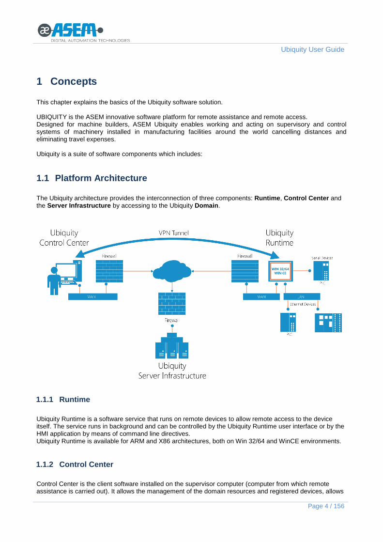
The Ubiquity architecture provides the interconnection of three components: Runtime, Control Center and the Server Infrastructure by accessing to the Ubiquity Domain.
1.1.1 Runtime
Ubiquity Runtime is a software service that runs on remote devices to allow remote access to the device itself. The service runs in background and can be controlled by the Ubiquity Runtime user interface or by the HMI application by means of command line directives. Ubiquity Runtime is available for ARM and X86 architectures, both on Win 32/64 and WinCE environments.
1.1.2 Control Center
Control Center is the client software installed on the supervisor computer (computer from which remote assistance is carried out). It allows the management of the domain resources and registered devices, allows

Ubiquity User Guide
Page 5 / 156
to connect to a specific device, to instantiate a VPN, to manage remote serial ports, and to use interactive tools as remote desktop, file exchange, etc..
1.1.3 Server infrastructure
The server infrastructure provides authentication and access control in a safe way. It also supports the handshake between Control Center and the Runtime. The infrastructure takes care of Control Center users identification, Runtime discovery and reachability of the same from Control Center. The infrastructure is geographically distributed and provides redundancy, fault tolerance and high performance.
1.1.4 Ubiquity Domain
The Ubiquity Domain is the customer account hosted on the network infrastructure and it is logically made but a group of devices, users, groups of users, firewall policies and permissions.
1.1.5 Connectivity
The basic requirement for Ubiquity functioning is the availability of a working Internet Connection for both Control Center and Runtime. Control Center and Runtime use always outgoing connections, normally allowed by the firewall systems. Control Center and Runtime act then as “clients” towards the central server, which instead accepts incoming connections. At least one TCP port among
80
443
5935 must be open
Port 8888 was used instead of port 5935 in Control Center and Runtime versions prior to version 4.
The first open port will be used to connect clients to the Ubiquity servers, and later to establish the end-to-end connection between Runtime and Control Center.
All Ubiquity connections, regardless of the port used, are made using the secure SSL/TLS protocol which is aligned with the state of the art of the technologies for a safe information exchange over the Internet network. The use of the SSL/TLS protocol allows Control Center to verify the identity of the Ubiquity Server and later the confidentiality of the information exchanged with the server and with the Runtime. Ubiquity Control Center provides furthermore the information about the validity of the certificate in use. The information are available in the “SIGN IN” screen from the link at the top right corner of the main screen, as shown in the following figure. .

Ubiquity User Guide
Page 6 / 156
Optionally, if at least an UDP port 80, 443, or 5935 outgoing port is available, Ubiquity will automatically use it when possible (i.e. for VPN connection) in order to improve connection performance. UDP normally provides lower latency and better stability when the Internet is congested.
Control Center shows missing UDP connectivity showing a warning sign ( ), on the side where the issue is located (Control Center, Runtime or both).
1.1.5.1 PROXY
The PROXY setup is available in the “Network” section, available from the “Settings” screen as shown in the following figure.
Click on the icon to expand and select the desired method providing the required information. Type can be one of the following:
None: no Proxy is used for the connection
HTTP: HTTP Proxy type, supports authentication with user name and password
SOCKS5: SOCKS5 Proxy type, supports authentication with user name and password

Ubiquity User Guide
Page 7 / 156
1.1.5.2 Connection options Control Center
The connection options are available in the “Network” section, which can be accessed from the “Settings” screen as shown in the following figure.
The "Port" drop-down menu is used to select the port that Control Center will use to connect to the infrastructure. The available options are the following:
Auto: use the first available port (TCP or UDP) 443, 80, 5935.
443: use port 443 to connect.
80: use port 80 to connect.
5935: use port 5935 to connect. The “P2P Connection” drop-down menu is used to enable or disable Peer-To-Peer connection between Control Center and Runtime. The following options are available:
Auto: use P2P to connect to the destination Runtime if possible, otherwise use a mirror server.
Disabled: use the connection via the mirror server without attempting the P2P approach. The “VPN transport” drop-down menu is used to select the communication protocol used the VPN tunnel. The available options are the following:
TCP (Default): use the TCP protocol
UDP: use the UDP protocol
In some network infrastructure it may be possible UDP packets are subjects of filtering or restrictions; anyway, it is possible to try using this protocol to reduce the latency time.
1.1.5.3 Runtime and Control Center connection?
Connection logic between Control Center and Runtime follows these rules:
Control Center connects to the Ubiquity servers and obtains the list of devices registered to the domain. The user can only see the devices he is allowed to see by the configured permission rules.
Runtime connects to the Ubiquity servers. This takes place when you click "Connect" on the Runtime control panel.
Control Center is notified by the Ubiquity Cloud that the Runtime is available for remote connection. The Runtime icon inside Control Center turns into green .
From now on, Control Center can connect at any time, activating Remote Desktop sessions or connecting the VPN.

Ubiquity User Guide
Page 8 / 156
When Control Center closes the connection to device, the device remains still available for further connections until someone clicks "Disconnect" on the Ubiquity Runtime panel.
If a Runtime is connected to the Ubiquity servers and it is restarted , the connection behavior depends on the option shown in the following figure.
1.1.5.4 Selecting the port for Runtime on Windows CE systems
To force Ubiquity Runtime to use a specific port, simply select it in the specific combo box on the “Options”
screen which can be accessed by pressing the gear icon . See the following figure.
Alternatively, in case the parameter is not available in the interface (old versions), you can manually edit the parameterization file following the procedure shown below.

Ubiquity User Guide
Page 9 / 156
If running close the Ubiquity Runtime. Locate the “config.xml” file in the following folder: \MMCMemory\Ubiquity Runtime (the above is valid for ASEM Systems; for any others note that the config.xml file is stored in the Runtime installation folder) and open it with a text editor. Add of modify the following line: <Param Name="ForcePort" Value="443" /> using as “value” the number of the desired port in between the three supported: 80, 443, 5935. Restart the system.
1.1.5.5 Selecting the port for Runtime on Win32 systems
To force Ubiquity Runtime to use a specific port, simply select it in the specific combo box on the “Options”
screen which can be accessed by pressing the gear icon . See the following figure.
Alternatively, in case the parameter is not available in the interface (old versions), you can manually edit the parameterization file following the procedure shown below. If running, close Ubiquity Runtime and terminate the service. To terminate the service open the Run window, type “services.msc” and click OK.

Ubiquity User Guide
Page 10 / 156
From the services list, locate the “Ubiquity Runtime Service” one, select it, click with the right mouse button and select the stop command. Locate the “config.xml” file in the following folder: C:\ProgramData\ASEM\Ubiquity\Runtime (for Windows Vista and newer) C:\Documents and Settings\All Users\Application Data\ASEM\Ubiquity\Runtime (for Windows XP) and open it with a text editor. Add of modify the following line: <Param Name="ForcePort" Value="443" /> using as “value” the number of the desired port in between the three supported: 80, 443, 5935. Restart the system.
1.1.5.6 Local connection
Ubiquity recognizes automatically the connection topology even when Control Center is behind the same LAN where also Runtime is connected. In this case the connection is still relayed to the Ubiquity servers, in order to correctly simulate the real world performances. A VPN connection in this case makes sense only if Control Center cannot access the Runtime private subnet, for which a network bridge has been configured.
1.1.5.7 Ubiquity server infrastructure IP addresses
The Ubiquity server architecture consists of a set of redundant servers designed for scalability and service continuity. Moreover, the choice of the server to which the Control Center and Runtime connect depends by the “best response time”. The system is designed to operate automatically without the need for any configuration or set any options.

Ubiquity User Guide
Page 11 / 156
Nevertheless, it is useful in some situations to know the exact address of the server on the Internet in order to configure specific rules in the security policies of the corporate network. Control Center and Runtime must be able to connect to at least the following addresses: ubiquityas1.asem.it ubiquityas2.asem.it ubiquityrs1.asem.it ubiquityrs2.asem.it ubiquityrs3.asem.it ubiquityrs4.asem.it ubiquityrs5.asem.it ubiquityrs6.asem.it ubiquityrs7.asem.it
The names will remain persistent in the future, while the IP addresses may be subject to change over time. It is anyhow preferable to set the rules in the firewall based on the names. Otherwise, it will be necessary to keep the IP updated over time.
1.2 Ubiquity Licensing Model
Ubiquity is available in two different license versions. The following table summarizes the differences.
Feature BASIC PRO
Interactive tools (Remote Desktop, File Exchange, Remote Task Manager, Chat, System Information)
Yes Yes
VPN limited to the device hosting Ubiquity Runtime Yes Yes
VPN extended to the remote device sub-network No Yes
Serial port pass-through No Yes
1.3 Ubiquity domain
A Ubiquity "domain" is the set of users, groups of users, remote devices and firewall policies in a given application context. Typically a company gets a Domain using for it the same company name and uses it to manage all remote devices and users that are allowed to connect and make operations such as remote maintenance or upgrades. Entities that can be part of an Ubiquity domain are:
Users A user is an access credential allowed to log into the Ubiquity domain and access remote machines. Ideally, you can create a user for each individual, each with its own password. To access the Control Center you need to enter the domain name and your username and password.
Groups A group is a set of users. Groups allow you to organize in a structured way users to manage accesses and priorities more easily and quickly. Example: creating "Administrators", "Italy", "Foreign", "Externals" groups lets easily separate users into organization units in order to manage accesses according to certain permissions.

Ubiquity User Guide
Page 12 / 156
A user can belong to multiple groups.
Device (Remote PC) A "device" in this manual is a synonym of remote computer or operator panel on which Ubiquity Runtime is installed. It can be reached using Control Center.
Folders A folder is a container of devices. With a paradigm similar to those of folder and documents on your computer, you can organize the devices in different folders. Folders can be added as desired.
A device can be part of one only folder.
Permissions Permissions are rules applied to users that allow or deny the access to remote devices.
Firewall policies Firewall policies are rules applied to VPN packets that control if certain protocols, ports, IP addresses, etc. are allowed or denied. The firewall’s policies have to be first imported or defined and later used by “applying” them to folders (and hence inherited by the devices within the folders) or directly to a single device. The policies are applied according to the logged user, so different users get different policies. Please see the chapter dedicated to firewall for a complete description of the function.
For further information on domain management using Control Center see the chapter “Using Domains“.

Ubiquity User Guide
Page 13 / 156
2 Control Center
Windows application to be installed on the supervisor computer that allows system configuration, remote device registration, remote assistance, configuration of security options for groups and users, with a user-friendly interface.
2.1 Requirements and setup
Control Center can be installed on the following operating systems:
Windows XP
Windows Vista 32-bit and 64-bit
Windows 7 32-bit and 64-bit
Windows 8 32 bit and 64 bit
Windows Server 2008 and Server 2008 R2
Windows Server 2012 The Control Center setup, verifies automatically the presence of the .Net Framework 4.0 Client Profile on the computer and automatically installs it if necessary. During the installation the following components are installed:
software files
a virtual network adapter
a virtual serial port that is used to access physical serial ports of remote devices. The installation script provides two setup options:
Complete
Custom

Ubiquity User Guide
Page 14 / 156
When selecting the “Custom” option the setup shows you the feature list for Virtual Serial Port installation.
Ubiquity Runtime version 1.3 implements a brand new Virtual Serial Port component, compared to version 1.2 or older.

Ubiquity User Guide
Page 15 / 156
To keep compatibility with the older Runtime, the installation script provides an option to install also the support for previous components. In case you do not need to support Ubiquity Runtime older than V1.3, you can remove the component called “Virtual Serial Port for Runtime 1.2 and older” from the actual installation.
Ubiquity Control Center ensures always backward compatibility supporting any older version of Ubiquity Runtime.
If you select to keep the support for Runtime V1.2 and older, you will be then asked to provide the COM port number to be assigned to the virtual serial port.
Ubiquity Control Center V1.3 and newer allow to select the Virtual Serial Port COM number when activating the Serial pass-through feature. This also allows to easily change the COM number at any time.
This is the serial port number you need to use in all the applications that require to communicate via serial line (PLC programming software). The traffic generated by the application over the virtual COM port, is automatically mapped by Ubiquity to the physical serial port on the remote device, using the Ubiquity VPN link. See later in this manual for specific information about how to handle Virtual Serial Port feature. The installation also adds a virtual Ethernet interface named "Ubiquity VPN", which is visible in the network control panel. The IP address of this card is automatically handled by the Control Center. Usually a static IP address compatible with the destination subnet that hosts the Runtime is assigned.
It is also possible to manually assign the IP address to the Ubiquity VPN adapter. Please see later in this manual for further information.

Ubiquity User Guide
Page 16 / 156
2.2 The Control Center user interface
When started, Ubiquity Control Center shows the Domain login screen as shown in the following figure.
Once the login form is filled, you can press the Connect button to login to the domain. If the credentials are accepted, you are redirected to the main view with the devices’ tree view as shown in the following figure.

Ubiquity User Guide
Page 17 / 156
With reference to the numbers in the above figure, the different areas and controls have the following meaning.
1. Tree view of the domain’s components; to make the view more simple to read, it support an automatic grouping mechanism of homogenous elements. Each folder can contain three different types of elements: Devices, Users/Groups and Firewall policies. When in a given folder we have elements of at least two different types and each of them is in number greater than one, they will be shown grouped as shown in the following figure.

Ubiquity User Guide
Page 18 / 156
2. The tree view is useful when you need to logically manage the domain contents, the users, the
groups, the permissions and the firewall rules. 3. The “ACCOUNT” link allows you to show the domain registration information together with the
activation details. 4. The commands at the top allow to show the grid view of the devices, the statistics and the page for
the Ubiquity Router configuration. 5. In this area, from left to right, you can find the following commands:
Add a device to the domain
Create a folder
Create users and groups
Definition and importing of firewall policies
Rename
Delete the selected element
View refresh
Please note that if the logged user does not have the rights to execute a certain command, the command will appear in grayed out mode.
6. The right side of the screen is divided in three parts; the visibility is controlled by the command on the left side of the name; the contents of each area changes according to the sleeted element.
7. Search box to execute searches within the tree view. 8. The menu to get access to the sign in page, to the settings screen and to the user manual. 9. The back command that displays the previously opened page in the order in which the screens are
visited. The settings page provide several options as shown in the following figure.
1. APPEARANCE allows to select the desired color schema
2. LOG shows the list of the operations done by Control Center during the connection phase to the server infrastructure and during the activation of the connection

Ubiquity User Guide
Page 19 / 156
with the Runtime
3. NETWORK allows to setup the PROXY
4. ABOUT shown the information on the version of the Control Center application
Control Center supports the keyboard shortcuts listen in the following table.
Keyboard shortcut Action Available in:
Backspace Back to the upper folder File explorer
F2 Open the pop-up to rename Domain tree, File explorer
CTRL+F Moves the focus on the search field Domain tree
CANC/DEL Deletes the selected elements with confirmation request
Domain tree, File explorer
F5 Refreshes the view Domain tree, File explorer
SHIFT+CTRL+N Creates a new folder File explorer
keyboard Moves the selections focus on the elements that starts with the typed letters
File explorer

Ubiquity User Guide
Page 20 / 156
2.3 Using Domains
The chapter describes how to create a domain, how to add devices to the domain and how to organize the domain using hierarchy relationships, users and groups. The firewall description is in the dedicated chapter.
2.3.1 Domain Setup
To use Ubiquity you need to authenticate as a user belonging to a particular domain. The first step in creating the configuration is the creation of a domain. Open the Control Center and click on the link “Create a new Domain” which is visible in the main view when you are not yet connected to a domain.
The following page opens and prompts for the following fields:

Ubiquity User Guide
Page 21 / 156
Fill in the form click “Create domain” and wait for server's reply.
Domain creation and use require a working Internet connection from the PC where Control Center is installed. See the chapter Connectivity for further information about requirements.
An admin user called 'admin' is created as default user. This user is special because it cannot be renamed, and you cannot remove administrator rights. This ensures that you cannot be in a situation where, by mistake, there are no more users with administrative rights on the entire domain. The 'admin' password is sent to the e-mail specified during the registration process. It is recommended to create additional users with administrative rights and leave 'admin' as an emergency administration user.
2.3.1.1 Domain Activation
Each newly created Domain is immediately working, but it requires a formal activation providing the license code, within a period of 30 days from creation. The following figure shows the warning message returned by Control Center.

Ubiquity User Guide
Page 22 / 156
The activation procedure of a Domain is supported starting from Control Center version 2 or above. If you are using a previous version of Control Center in combination with a new Domain, the user is properly advised to update the Control Center application without any data loosing.
The license code for the Domain activation is part of the “Ubiquity Domain License” package to per purchased. In case the Domain is not activated within the trial period, the access will the blocked and its contents will be frozen. The user’s data will not be deleted and all will return back usable in case the Domain will be later activated.
2.3.2 Organizing the domain
The tree view of the domain can be freely customized accordingly to the specific requirements and needs of each single Ubiquity user. In particular Control Center supports the creation of folders and sub-folders nested as needed. This is especially useful if you want to create different access rules depending on users.
Permissions can be assigned to the folders as well singularly to the devices. Devices in each folder are inheriting the permission from the father folder. The assignment of permissions (deny or allow) to a single device permits to specify an exception in compare to the inherited behavior.

Ubiquity User Guide
Page 23 / 156
To create a folder, go to Control Center with an administrator account belonging to the domain (see below in this document the chapter about the permissions to know which profile is required to operate on the domain). After the user login the default tree view is shown; click on the root or onto an existing folder to create a subfolder. You can proceed in two ways:
Click with the right mouse button and select the command “Create folder”
Use the command in the top toolbar
To rename a folder, you can use right click over the name and select the Rename command or click on the rename icon in the upper part of the window, as shown in the following figure.

Ubiquity User Guide
Page 24 / 156
You can create an arbitrary set of folders and subfolders. To insert a device in a sub folder just drag and drop the device icon into the folder itself.
If at the moment of adding a new device to the domain, you select a folder different from the root, the new device will be inserted in the selected folder.
2.3.3 “Devices” view and searches
From the main screen when you click on the “devices” button you get the grid view.

Ubiquity User Guide
Page 25 / 156
The table view of the devices represents all the domain elements in a grid format with several columns. The width of each column can be adjusted as desired simply clicking with the mouse of the vertical separation line between the columns and dragging. The order of the columns in the grid can be also freely changed with a simple drag&drop starting from the column title. The not visible column can be reached using the horizontal scroll bar at the bottom of the window. The table can be sorted based on the several columns contents; to sort the table according to a column contents it is enough to click on the column title. The customizations at the grid view are retained at users change and they are valid regardless of the connected user. The remote assistance session can be activated also from the grid view with a simple double click on the row (Remote desktop). When you click with the right mouse button you get access to the following commands:
Remote access (equivalent to the double click)
Connect VPN (direct VPN activation without to display the remote desktop)
Locate in the tree view (locate the selected device in the tree view) The grid view allow to execute searches all over the entire domain using the search box in the top right as shown in the following figure. The search is by text and the search results are shown still in a table but with a limited number of rows according to the devices which match the researched characters.

Ubiquity User Guide
Page 26 / 156
The search results correspond basically to the application of a view filter that can be removed by clicking to the small “x” on the right side of the text field. The search function is also available in the tree view as shown in the following figure. The use of the search in the topological view shows the results in terms of a reduced tree.

Ubiquity User Guide
Page 27 / 156
2.3.4 Ubiquity Domain Users
Ubiquity control Center allows defining the domain’s users assigning to them permissions based on the combination of a number of different predefined profiles. There are two separated steps in the users creation:
Users and groups definition
Permission assignment based on profiles This chapter describes the users and groups creation. See the chapter “The profiles” for information about how to handle the permissions. Because a domain can be organized according to a tree hierarchy structure made of folders and sub folders nested at any level (see the chapter about the Domain organization for additional details) the users can be defined with validity (scope) restricted to the tree leaf in which they are defined. To simplify the identification of the users’ scope, Control Center displays them within the sub folder where they are created. The users will be then displayed in the tree as “leaf elements” of the folder where they have been defined in the same way as the devices. As an example, please see the following figure where the devices “HMI25” and “HMI30” are local to the folder “Folder 1.1.1”.

Ubiquity User Guide
Page 28 / 156
With reference to the previous figure, the “User 1” is local to “Folder 1”; it will be available to assign permission within all the leafs starting from the folder where the user has been created, including the devices directly attached to the root (not inserted in any sub folder). The user “User 1.1” is local to “Folder 1.1”; it is available within “Folder 1.1” and within all the sub folders of “Folder 1.1”, but not in any parallel or above level. For example, it will not be usable as user of a device within “Folder 1.2”. In the same way the user “User 1.1.1” is local to “Folder 1.1.1”. The mechanism can be naturally extended to all the elements shown in the picture.
The users defined locally to a certain folder do NOT have visibility of any users defined in the upper levels The accessibility to the inherited users can be given directly using the “Access users” permission (see the chapter dedicated to the profiles) from the upper level.
After a user has been created with its scope, it will get some permissions in terms of any possible combination of profiles that can be applied to folders and devices. Please see the chapter dedicated to the profiles for further information.
2.3.4.1 The subdomain
The possibility to define users and groups with restricted scope and to assign to them the administration rights over the same folders, allows basically to create subdomains that are completely independent and can be freely organized by the local administrators. Please see later which profiles shall be assigned to the local users in order to act as local administrators. The full control of any subfolder is still possible by the administrators of the above levels (the ramification is in fact inheriting the permissions assigned to users and groups of the above levels).

Ubiquity User Guide
Page 29 / 156
The subdomain is a feature that permits the organized used of the “Multi Entity” Ubiquity domains when they need to be used by different companies. In similar scenarios is in fact reasonable to design the domain using subdomains: there will be one subdomain per each company that requires to use the domain. Each of those companies will be administrators of its subdomain, without any visibility of folders and devices of the others tree ramifications.
2.3.5 Creating users
To create a new user within your own Ubiquity domain is required an access by a user to which it has been assigned the “Manage users” permission. When a domain is created, you also get a user called “admin” with all the available profiles. You need to use the “admin” credential to start configuring your domain.
It is recommended to create at least one user different from “admin” to be used for remote access operations and leave the user "admin" only for managing operations of the devices and users database.
To create a user local to a folder, click first on the folder and use then the command to create the user as shown from the following figure.
It is also possible to use the “Create user” command available in the right click contextual menu over a folder. The user creation requires the name and the password as shown in the following figure.
Once the user is created, click on its name to display on the right side of the window its properties as shown in the following figure. The users with “Manage users” permission can use this screen to change the password to the other users.

Ubiquity User Guide
Page 30 / 156
2.3.5.1 Time limited users’ accounts
Per each user it is possible to define a time limit for the validity of the account. Each user has a parameter called “Expiration date” to specify a date after that the account will be disabled; a connection attempt with the account after the date specified will be rejected and a proper message will inform the user to contact the Domain administrator. The account is not removed, ne invalidated the password, but simply blocked, not usable. The parameter is in the user properties as shown in the following figure.
The time limited users’ account is supported starting from Ubiquity 2
2.3.5.2 Change of User’s password
Each user can change his password at any time. After you are logged into the domain, click on "Change my password" in the "Network" panel, as shown below.

Ubiquity User Guide
Page 31 / 156
Administrator users can create and change password for any user
2.3.6 Creating Groups
Groups are collections of users. They are useful to better organize permissions between users. To create a group you need to log into Control Center as an user with administration profile. To create a group local to a certain folder, select first the folder and user later the command for the group creation as shown in the following figure.
It is also possible to use the “Create group” command available from the right click contextual menu over an existing folder. In the next window you need then to provide the name for the group being created.

Ubiquity User Guide
Page 32 / 156
2.3.7 Associating Users to Group
Each user can be associated with one or more groups. The association can be done in two ways: 1. From the “MANAGE” view select the group in the list on the left. Press the button "Add user", select the user from the list and confirm with OK.

Ubiquity User Guide
Page 33 / 156
2. Drag the user icon and drop it into the group icon.
2.4 User permission management
Control Center allows defining permissions for users and groups; groups are assigned to folders and the devices within the folders inherit the permissions. It is also possible to assign permissions directly to a single device. Rules assigned to subfolders and device “override” the rules applied to their parent folders. Permissions for a certain user within a group can be changed overriding the folder’s ones.
2.4.1 Profiles and Access control
The permissions to users and groups are assigned in terms of profiles. The first step is the selection of the folder or device for which you need to set access rules. Once the element is selected, open the “Permission” section on the right side of the main window. It shows in the top the list of groups and users with at least a permission (granted or denied) on the selected element (folder or device). If you have selected a device rather than a folder, the list will be related to the single element. The bottom part identifies the permissions granted or denied using a combination of “profiles”. If a certain group or users gets a certain profile, it means that it can do all the actions related to the profile. The combination between granted and denied permissions, both in positive and negative way, allows the maximum level of flexibility while modelling the domain access rules to the user requirements.

Ubiquity User Guide
Page 34 / 156
2.4.1.1 The Profiles
There are four different types of profiles for the permission assignment. Each profiles grants to user or group a specified set of actions. The profiles are the following:
Administration: everything related to the domain organization in terms of folders and access control; it has also access to the statistics.
Network Security: everything related to the firewall configuration
Device Installer: enables only the association of the devices to the domain and organization within the existing and accessible folders
Device access: online session operations The “Administration” profile contains granular permissions according to the following list:
Access users access to the users defined within the path where the permission is given
Manage users create users, edit users, delete users and permission assignment
View statistics access to the statistics The “Device access” profiles is additionally dividend in specific actions according to the following list:
View the Desktop remote desktop view only, no possibility to interact
Interact with the desktop full remote desktop interaction
Network access (VPN) VPN activation and sub network access; the sub network access can be additionally filtered by applying the firewall policies.

Ubiquity User Guide
Page 35 / 156
Serial pass-through use of the serial pass-through function (this option is conditioned to the activation of the VPN, hence it is not available without the VPN access.
Read remote files read files from the remote system via file manager
Write remote files write files to the remote systems via file manager
Chat use of the chat
System and processes access to the remote processes viewer with possibility to kill them and restart of the remote device
2.4.1.2 Permission assignment
To assign the managing and remote access permission to a certain user o group, you need to reiterate the following steps:
- Select the folder or the device to which the permissions have to be applied - Make the association between the selected element and the group or user - Assignment of the profiles to the user or group associated to the folder or device
To associate a group or user to a folder, open the “MANAGE” view in Control Center, select the folder, display the “Permissions” area on the right side of the windows and click on the “Add” button as shown in the following figure. From the list select then the user or group to be added and confirm with the OK button.
In the above example you see the group “Italy” associated to the folder “Italy”. This means that the users belonging to the “Italy” group will get access to the devices contained in the folder depending on the given permissions.

Ubiquity User Guide
Page 36 / 156
You need now to assign which permissions are granted to the group. The permissions are assigned using the check boxes in the “Permissions” area below the users/group list. At any level the table shows the resulting permissions applied to the selected element; note also that for a given profile, if there is no marked check box (both Allow and Deny cleared), this corresponds to a “Deny”.
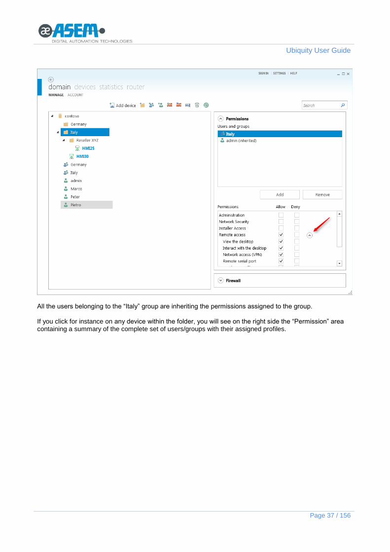
In the above example the Italy” group has the permission to execute the “Remote access” on the devices within the folder. In case you need to specify an additional granularity in the remote access, you just need to expand the list and uncheck the operation you want to block. See the chapter about the profiles for additional information.
Ubiquity User Guide
Page 37 / 156
All the users belonging to the “Italy” group are inheriting the permissions assigned to the group. If you click for instance on any device within the folder, you will see on the right side the “Permission” area containing a summary of the complete set of users/groups with their assigned profiles.

Ubiquity User Guide
Page 38 / 156
The column “Deny” allows to block a specific action for the selected group or user. In the above example the folder “Reseller XYZ” inherited from the father folder the permissions assigned to the “Italy” folder. Control Center allows to specify a specific exception at user level. This is useful for instance when you need to handle a user of a group in a different way than the group.
The evaluation of the permissions is made according with the following priority: Explicit Deny Explicit Allow Inherited Deny Inherited Allow
It is possible for instance to specify a specific restriction for the user “Pietro” in compare with its group and related to the “Reseller XYZ” folder.

Ubiquity User Guide
Page 39 / 156
To specify an exception for a user, you need first to add the user to the list and later to specify what is different for it. As shown in the previous figure the permission is denied in an explicit way (there is no “inherited” next to the user name). The “Deny” is applied marking the checkbox “Deny” for the operation “Device Access” once the user “Pietro” is selected in the above users and groups list. Assuming “Pietro” belongs to the group “Italy”, he will have access to all the devices within the “Italy” folder, except for the ones in the “Reseller XYZ” folder. In case the restriction has to be applied to a single device rather than a complete folder, you will just need to select the device instead of the folder before to specify the “deny” permission. Logging in to the domain with the user “Pietro” you can see the user does not even have the visibility of the denied folder.

Ubiquity User Guide
Page 40 / 156
2.4.1.3 How to create a sub domain
In this example we see how to create a sub domain with local administrator. The target is to create a sub domain called “Germany” with some sub folders and to get a user (Claus) as administrator of this sub domain. You need first to access to the main domain with a user having Administration profile for the domain. Create then the folder “Germany” and the two sub folders “Nurnberg” and “Stuttgart”. While the “Germany” folder is still selected creates now two users that will be local to the selected folder. Andreas and Claus will be users available only within the “Germany” folder. The result is shown in the following figure.

Ubiquity User Guide
Page 41 / 156
To elect Claus as administrator of the “Germany” sub domain, click on the folder name and add the user to the list on the “Users and groups” list of the “Permission” area. Assign then to Claus the administration profile. The result is shown in the following figure.

Ubiquity User Guide
Page 42 / 156
Please note that in the moment the user Claus is added to the sub domain users’ list, the window shows the complete list of domain’s users.
When you log in to the domain with the user “Claus” you get the situation shown in the following figure.

Ubiquity User Guide
Page 43 / 156
You see immediately that the user has no visibility of any folder out of the “Germany” one and it does not have any permission at domain root level. When you click on the “Germany” folder, all the commands and controls become immediately accessible according with the administration profile.
Claus potrà ora creare utenti e gruppi all’interno del suo sottodominio.

Ubiquity User Guide
Page 44 / 156
The described procedure is recursive and allows for instance to Claus to create an additional sub domain with others local users. In case Claus is still using a previous version of Ubiquity Control Center, the situation will be the one shown in the following figure where the controls to crate folders, users and groups are not available.

Ubiquity User Guide
Page 45 / 156
2.4.1.4 Compatibility
The “Network security” and “Installer” profiles are supported starting from Ubiquity Control Center 3. The support for granular profile management has been introduced in Ubiquity Control Center 3. The granular permissions within the “Device access” profile is supported from Ubiquity Control Center 3. If you use Control Center 3 or greater in combination with Ubiquity Runtime 2 or earlier, the granular permissions are not applied unless they have been market altogether. Example: if you have assigned only the “View desktop” and “Interact” permissions, they will not be actually applied and the result will be a user with NO device access at all. If you want to grant the device access permission you will need to mark all the granular permissions. The granular permissions within the “Administration” profile are supported from Ubiquity Control Center 5. If you use Control Center 5 or greater in combination with Ubiquity Runtime 4 or earlier, the granular permissions are not applied unless they have been market altogether. Example: If you assign only the permissions “Manage folders” and “View statistics”, they will not be actually applied and the result will be a user with NO administration permissions at all. If you want to grant the administration permission you will need to mark all the granular permissions. The following table summarize the actions permitted per each profile comparing them with older versions.
2.0 3.0 – 4.0 5.0
Administration U= Access users / Manage users A= Access users M= Manage users F= Manage folders S= View statistics X= All (admin)
Adm
inis
tration
Assis
tance
Adm
inis
tration
Insta
ller
Devic
e a
ccess
Netw
ork
Security
A
dm
inis
tration
Insta
ller
Devic
e a
ccess
Netw
ork
Security
Devices
Add a device to a Domain X X X
Remove a device from a Domain X X X
Move a device from a folder X X X
Rename a device X X X
License a device X X X
Remove the license from a device X X X
Remote handling X X X X
VPN X X X X
Add a permission to a group or to a user X X U
Remove a permission from a group or a user X X U
Modify a permission for a group or a user X X U
Get the list of permissions X X U
Folders
Create a folder X X F
Delete a folder X X F

Ubiquity User Guide
Page 46 / 156
Rename a folder X X F
Add a permission to a group or to a user X X F
Remove a permission from a group or a user X X F
Groups
Add a group X X M
Delete a group X X U
Rename a group X X U
Get the list of the groups X X U
Move a group X X U
Users
Add a user X X M
Remove a user X X U
Rename a user X X U
Get a user X X A
Change password to a user X X U
Change the expiration date of a user X X U
Add a user to a group X X U
Remove a user from a group X X U
Obtain the list of the users X X A
Get the list of the groups to which a user belongs X X A
Move a user X X U
Change a user X X U
Domain
Create a domain X X X X X X
Change domain information X X X
Activate a domain X X X
Generate domain identities X X X
Satistics
Get statistics X X S
Router
Router managing X X
The versions 2 have onlyh two available profiels (Administration and Remote Desktop). They are mapped in the profiles of newer versions accordign to the followign table.

Ubiquity User Guide
Page 47 / 156
2.0
Adm
inis
tration
3.0
- 4
.0
Adm
inis
tration
5.0
Adm
inis
tration
Access users
Manage users
Manage folders
View statistics
Device Installer Device Installer
Devic
e A
ccess,form
er
Re
mote
Deskto
p
Devic
e A
ccess
View the desktop
Devic
e A
ccess
View the desktop
Interact with the desktop
Interact with the desktop
Network access (VPN)
Network access (VPN)
Serial passthrough
Serial passthrough
Read remote files
Read remote files
Write remote files
Write remote files
Chat Chat
System and processes
System and processes
The “Administration” and “Device Access” tables are including all the granular options. All the domains created with older versions of Ubiquity Control Center are fully compatible with the actual version. The permissions are granted according to the most conservative approach.
In case you have used the Device Access granular permissions, a version 2 user will get NO device access at all.
In case you have used Administration granular permissions, a version 4 (or older) user will get NO administration at all.
In case you have configured with version 3 some local users to some folders and those users use Control Center 2, they will get access, but no control on the local and domain users.
With reference to the example of sub-domain creation, if Cluas uses Control Center 2 he will get the situation shown in the following figures where the controls for groups, users and folders creation are not available.
Ubiquity User Guide
Page 48 / 156
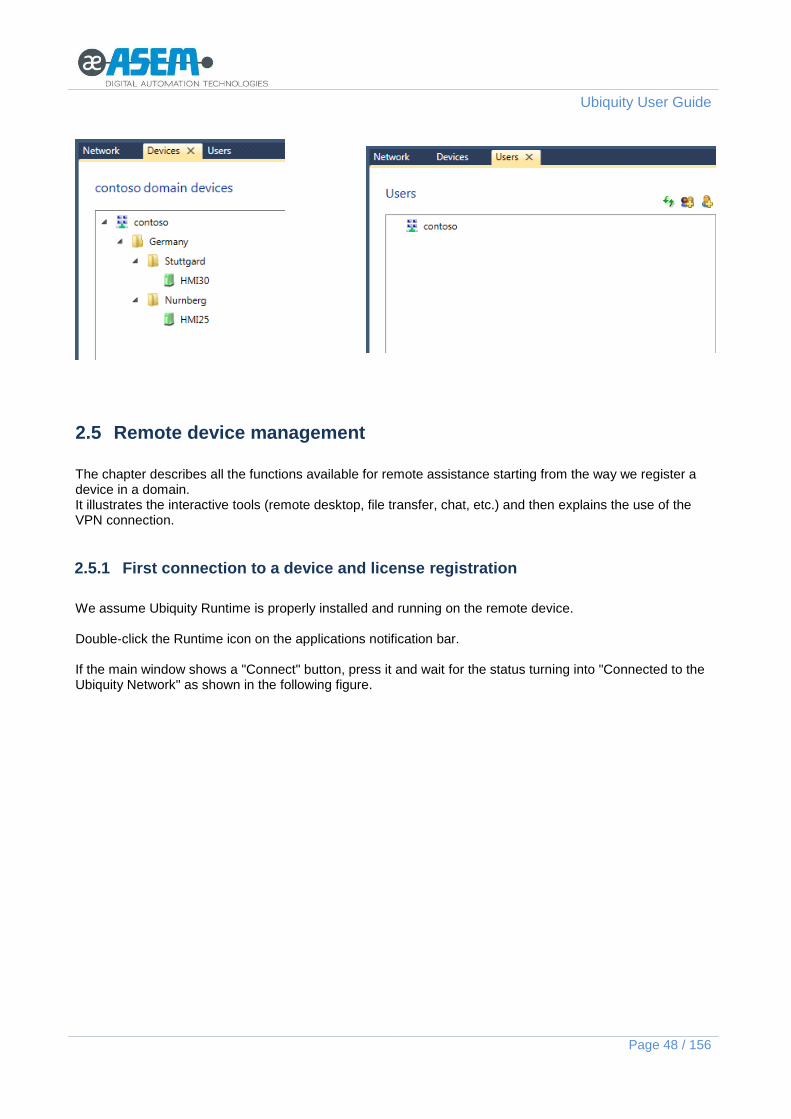
2.5 Remote device management
The chapter describes all the functions available for remote assistance starting from the way we register a device in a domain. It illustrates the interactive tools (remote desktop, file transfer, chat, etc.) and then explains the use of the VPN connection.
2.5.1 First connection to a device and license registration
We assume Ubiquity Runtime is properly installed and running on the remote device. Double-click the Runtime icon on the applications notification bar. If the main window shows a "Connect" button, press it and wait for the status turning into "Connected to the Ubiquity Network" as shown in the following figure.

Ubiquity User Guide
Page 49 / 156
If the device where Ubiquity Runtime is installed is not registered yet to any domain, the main panel shows an ID code and password that should be used from Control Center to register the device into the Ubiquity domain. A user with administrator rights has to log into the domain from Control Center. Once connected, click on the folder where you need to insert the new device and click on the “Add device” button in the tools area as shown in the following figure.

Ubiquity User Guide
Page 50 / 156
Click then on "Add device" button and the device will be added in the desired position. The device can be then renamed and moved freely. In case the Runtime component running on the remote device just registered, has never been licensed, you can insert here the license code, by clicking on the "Register" link and enter the license code as shown in the following figure.

Ubiquity User Guide
Page 51 / 156
Device registration can be done also directly from the device using the dedicated command in the Runtime; see the chapter “Device registration and licensing” for further information.
Please note the difference between the “connection” of a device (Runtime) to a Domain and the license “registration”. The connection is a link between the Runtime (with its related license) and a Domain. This link can be changed any time you need. The connection is removed simply deleting the device from the Domain. The remote device will show again the ID and password for a new connection. The registration is instead a binding between a license code and a specific hardware system. The binding can be changed only a limited number of times. In other words, the same license code can be used with a limited number of different devices. The license registration is similar to a “token” which is used to activate the Runtime and can be moved across the devices a limited number of times.
To initiate an assistance session you can use the Device access and VPN buttons from the right pane.
2.5.2 Un-binding the license registration (Unregister)
The license registration for a certain hardware system can be cancelled (un-binding) to allow for instance a transfer to another device. The register un-binding can be done using the “Unregister” command available from the screen with the device details as shown in the following figure.

Ubiquity User Guide
Page 52 / 156
The license un-binding can be done for maximum two times. Each additional license movement requires a direct contact with the technical support team.
2.5.3 Remove and move devices
A device associated to a Domain can be deleted at any time and moved, if required, to another Domain. The operation can be done freely and with no restrictions. Please see the note about the difference between the “connection” of a device to a Domain and the Runtime license registration. To delete a device from a Domain, just click once on the device icon and execute the Delete command from the contextual menu or from the icon in the top of the tree view box. After the device has been removed, at the next connection of the removed Runtime to the Ubiquity server, it will show again the ID/Password information required for a new Domain connection If Ubiquity Runtime is connected to the Server while doing the removal, it will be immediately updated and the new ID/Password information will be displayed.
2.5.4 Remote Serial Connection
Control Center setup installs on the computer a virtual serial port which is required to support the remote serial port virtualization and pass-through function.

Ubiquity User Guide
Page 53 / 156
This port is actually mapped by Ubiquity to a physical serial port on your remote PC by using the VPN connection. To connect the remote serial port, a VPN connection must be instantiated. Once VPN is connected, press on the "Serial Pass-through" button on top to open the remote serial port configuration. On the left the Control Center local virtual COM port is shown. Local third party software must use this COM number in the serial communication setup. On the right you can choose the physical remote port number to connect. Once you click "Connect", the local virtual port and remote physical port are tunneled through Internet. Wait a few seconds until the status shows "The remote port is connected".

Ubiquity User Guide
Page 54 / 156
Ubiquity uses three types of encapsulation methods:
Data only: this setting remotes only data; it requires the manual setting of the serial communication parameters.
Data + Port configuration: this setting remotes both data and port configuration; the port will be automatically configured by the system.
Data + Port configuration + Data signals: this setting remotes data, port configuration and control signals.
Ubiquity supports serial pass-through with both half and full duplex connections at remote physical serial port
Some serial protocols of automation devices are very sensitive to latency, and the remote serial communication could not work, even in the presence of very good connection times.
You can connect only physical serial ports not in use by other applications running on the remote PC. If this is the case, you must close the applications that lock the serial port before connecting the remote port using Control Center.
In version 4 some serial configuration settings has been modified. Modifications are reported in the table below.
Version 3 (or lower) Version 4 (o higher)
Incapsulation
Telnet (RFC 2217) Data + Port configuration + Data signals
RAW Data only
Transport options Nagle’s algorithm Not supported
Stricted baud rate Not supported
2.5.4.1 Limitations
The proper operation of the serial pass-through is strongly dependent by the Internet connection quality on Control Center side and Runtime side. We can say an acceptable roundtrip time can be around 100-120ms. What is hardly impacting on the proper operation of the serial pass-through is the jitter of the ping time which should be less that 30-40% and the number of dropped packets which should be near to zero.
2.5.5 Remote Desktop
The Remote Desktop function of Control Center allows you to view and interact from remote with the device screen on which Ubiquity Runtime is running.

Ubiquity User Guide
Page 55 / 156
To start a Remote Desktop session, click on the device icon from the tree view and press the “Remote Desktop” button from the right side of the window. Alternatively, just double click on the device icon directly from the tree icon.
You can work directly on screen using the mouse and the keyboard. Through the Remote Desktop feature you can also take a snapshot of the screen saving it to an image file by clicking on the button at the top left "Screenshot". You can configure the graphic quality of the remote desktop in order to promote the transfer speed or quality. There are three possible options:
Hi color lossless: 65,000 color quality without compression. It is the slower configuration but with better quality.
Hi color lossy: 65,000 color quality but with JPG compression. It is very fast in presence of graphic images with many colors and shades, but worsens the quality of the text.
Low color lossless: 256 color quality with compression. It is usually the fastest option, but it has low images quality.
The "Lock input” " button can be used to lock and unlock the remote input devices (mouse and keyboards eventually connected to the device). By this way only Control Center can interact with the remote desktop by emulating mouse and keyboard. If you click on the "Original size" button, you can modify the resizing mode of remote desktop when it is too large to fit the Control Center window. If you click the "Ctrl-alt-del" button, you can send that key combination to the remote device.

Ubiquity User Guide
Page 56 / 156
The “Toggle chat” button turn on and off the chat. The Remote Desktop supports the copy&paste of text elements between local and remote.
2.5.5.1 Multiple RDP sessions
If Ubiquity Runtime is installed on a Windows Server operating system allowing multiple Remote Desktop sessions (Terminal Services), Ubiquity Control Center allows to select the session with which to start the remote desktop. This session can be selected by means of the specific menu as shown in the following figure.
2.5.6 Explorer (file transfer)
The file exchanging feature allows you to copy files to and from the remote PC like Windows Explorer. Once connected to the remote device via the Control Center, click on the "Remote Explorer" button. This will open a panel divided in two parts: the left panel displays the files located on the local computer running Ubiquity Control Center while the right panel shows the remote device files.

Ubiquity User Guide
Page 57 / 156
It is possible to copy files from remote to local or vice versa simply by selecting files in the source panel and clicking Send or Receive, depending on which direction you want the files to be copied. In case the file transfer is interrupted for any reason, it can be resumed from the point it stopped or can be restarted from the beginning (resume is a feature supported starting from Ubiquity version 2)

Ubiquity User Guide
Page 58 / 156
To rename a file or folder, right-click and select "Rename". Then insert the new name in the panel appearing in the foreground. You can also run remote processes selecting an executable file in the "Remote File System" area, right clicking and selecting "Execute remotely". When a panel displays the root folder of the device disk, it also shows the direct link to the system folders such as “Desktop” and “My Documents” folders (this is supported starting from Ubiquity version 2).

Ubiquity User Guide
Page 59 / 156
Ubiquity User Guide
Page 60 / 156
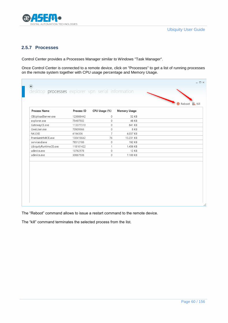
2.5.7 Processes
Control Center provides a Processes Manager similar to Windows "Task Manager". Once Control Center is connected to a remote device, click on "Processes" to get a list of running processes on the remote system together with CPU usage percentage and Memory Usage.
The “Reboot” command allows to issue a restart command to the remote device. The “kill” command terminates the selected process from the list.

Ubiquity User Guide
Page 61 / 156
2.5.8 Information
By clicking the "System Information" button you can have a brief overview of the operating system information, network configuration, CPU usage and memory resources.

Ubiquity User Guide
Page 62 / 156
2.5.9 Chat
The “Chat” feature allows the connection usage to communicate with the operator in front of the remote PC. To activate this feature you have to click on "Toggle Chat" button from the toolbar at the top when the remote desktop is displayed and write in the box that appears on the right.
All messages will be sent to the remote device's screen, on which the operator could answer by using a physical keyboard or the Windows software keyboard. The above figure shows how the chat looks from a remote desktop session; on the right side there is the “Chat” column in Control Center, on the left you see from Remote Desktop the display of the remote device The chat feature supports multiple RDP scenarios with identification of the message sender. In case you use the chat from more than one Control Center connected to the same Runtime, the messages sent by the Runtime are delivered to both Control Center clients, while any client cannot see the messages sent by the other.

Ubiquity User Guide
Page 63 / 156
2.5.10 Virtual Private Network (VPN)
Both Control Center and Runtime install a virtual Ethernet adapter to allow VPN connection. The access to the VPN is possible by pressing the dedicated button on the right pane or directly from the device window previously opened because of the Remote Desktop.
Click on the VPN button to open the screen with the network connection. The following figure shows an example with some devices connected to the Ethernet sub network of the remote device.
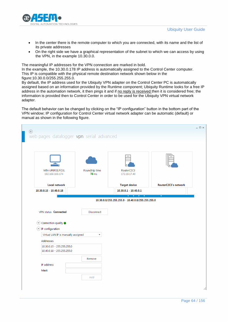
Pressing the “Connect/Disconnect” button you can connect and disconnect the VPN. The screen shows three blocks representing the following entities:
On the left side there is the supervisor computer, the one with Control Center installed, with its name and IP address
Ubiquity User Guide
Page 64 / 156
In the center there is the remote computer to which you are connected, with its name and the list of its private addresses
On the right side we have a graphical representation of the subnet to which we can access by using the VPN, in the example 10.30.0.0.
The meaningful IP addresses for the VPN connection are marked in bold. In the example, the 10.30.0.178 IP address is automatically assigned to the Control Center computer. This IP is compatible with the physical remote destination network shown below in the figure:10.30.0.0/255.255.255.0. By default, the IP address used for the Ubiquity VPN adapter on the Control Center PC is automatically assigned based on an information provided by the Runtime component; Ubiquity Runtime looks for a free IP address in the automation network, it then pings it and if no reply is received then it is considered free; the information is provided then to Control Center in order to be used for the Ubiquity VPN virtual network adapter. The default behavior can be changed by clicking on the “IP configuration” button in the bottom part of the VPN window; IP configuration for Control Center virtual network adapter can be automatic (default) or manual as shown in the following figure.

Ubiquity User Guide
Page 65 / 156
In case the Runtime network exposes two or more IP addresses of different logical sub networks, Control Center will assign to the Ubiquity VPN adapter two or more IP addresses each one compatible with a remote sub network. The IP addresses can be also manually assigned as shown in the previous figure.
In the example above the remote device can be reached through the IP address 10.30.0.30. Any application running on the computer hosting Control Center is now able to reach the remote device in the same way as if it were actually connected with a cable through the Ethernet adapter called "Ubiquity VPN". You can verify the connection status with the "ipconfig.exe" command.
You can also ping the 10.20.0.30 address.

Ubiquity User Guide
Page 66 / 156
2.5.11 Connection quality measurement
For information scope Ubiquity Control Center shows the results of the connection quality measurement on both partner sides. The measure is executed in the moment the VPN window is shown and in the moment you click the “Connect” button to activate the VPN connection. During the time the VPN is connected, the roundtrip factor returns instead a real time value. The measure is related to both connections, Control Center and Runtime. The measured parameters are the latency, the jitter and the percentage of lost packets. Based on the results Control Center provides a quality information using the colors red, orange or green for the ball point indicator. The following figure shows an example.
2.5.12 VPN connection scenarios
Ubiquity uses a data-link level 2 VPN, that is equivalent to a virtual Ethernet cable between the supervisor PC and the remote device. The Ubiquity protocol automatically assigns a static IP to the Control Center computer so that it can communicate at the IP level with the remote device and the connected devices.

Ubiquity User Guide
Page 67 / 156
There is no need for static routing rules and applications on the Control Center machine can communicate with the remote applications by simply using the physical destination IP addresses. The following VPN connection topologies are supported:
VPN connection to the remote device only (Basic and Pro licenses)
VPN connection to the entire remote subnet with 2 Ethernet cards (Pro license only)
VPN connection to the entire remote subnet with 1 Ethernet card (Pro license only)
VPN connection to the remote device only by using physical IP addresses (Basic license) See the chapter about Configuring the VPN for more information about how to implement network settings on the remote PC.
2.5.12.1 VPN connection to the remote device only
In this scenario, the remote device and the Control Center computer acquire a virtual IP (eg 10.8.0.0/255.255.0.0) that allows them to communicate. However, the PC running Control Center is unable to access any Ethernet device connected to the subnet of the remote device.
This scenario is compatible with BASIC and PRO licensing models.
2.5.12.2 VPN connection to the remote device only by using physical IP addresses
This is a variant of the “VPN connection to the remote device only” that allows Control Center to connect to the remote device by using the same physical LAN IP subnet, instead of virtual IP addresses. This can be convenient when the supervisor needs to access server applications that bind to the physical IP only.

Ubiquity User Guide
Page 68 / 156
The configuration is the same as for “VPN connection to the entire remote subnet with 1 or 2 Ethernet interfaces”, so that the Control Center computer can effectively join the physical LAN subnet, except that, by Runtime Basic license limitations, only IP traffic to the device IP is encapsulated through the VPN. This scenario is compatible with BASIC and PRO licensing models.
2.5.12.3 VPN connection to the entire remote subnet with 2 Ethernet interfaces
This is the ideal scenario when you need VPN access not only to the remote device but also to the entire subnet. In this case, the remote device has 2 physical Ethernet interfaces. The first is called “WAN” and is dedicated to Internet access; it is somehow configured by the local IT administrator (eg by a DHCP). The second is called “LAN” and it is dedicated to the communication between automation devices. Normally it is configured with a static IP and does not have a configured gateway. The Control Center computer can accesses the remote devices and applications through the LAN IPs (10.30.0.0 in this example), not the WAN IPs (192.168.168.150).
This scenario is compatible only with PRO licensing model.
2.5.12.4 VPN connection to the entire remote subnet with 1 Ethernet interface
In this scenario, the remote device has only one network interface, used to access both the automation devices and the Internet.

Ubiquity User Guide
Page 69 / 156
If you configure Ubiquity to give access to the entire network, the Control Center computer will become part of the remote network, without separation between LAN and WAN. You can also configure a runtime with a single Ethernet card to use two different IPs. In this case, the Control Center will behave similarly to the aforementioned situation: "VPN connection to the entire remote subnet with 2 Ethernet cards." See the Runtime documentation for instructions on how to configure the VPN on the remote device.
This scenario is compatible only with PRO licensing model.
2.5.13 Statistics and reports on service use
From the main Control Center screen a user with administration profile can access to the statistics of use of the service by clicking on the “Statistics” button. The statistics can be extracted for a specified time period and filtered by user or device. The “Save” commands allows to export the data in CSV format.

Ubiquity User Guide
Page 70 / 156

Ubiquity User Guide
Page 71 / 156
3 Runtime
Ubiquity Runtime is the software component that has to be installed on the remote device you need to control; Ubiquity Runtime is available for classic HMI devices, but also for PC Based systems. Ubiquity Runtime is available for all Windows platforms, from Windows CE to all Win32 based platforms (XP, Vista, Win 7, Win Server 2008 and Windows 8).
3.1 Runtime for Windows CE Platform
Ubiquity Runtime requires the .NET Compact Framework 3.5 or higher. For all ASEM systems with Windows CE the .NET Compact Framework is already pre-installed. If for any reason it is not present, you need to manually install it. You can get the Compact Framework from the following link: http://www.microsoft.com/download/en/details.aspx?displaylang=en&id=65 Once NETCFSetupv35.msi is downloaded, install it on a Windows machine XP/Vista/7. After installation you will have the following files on your computer: C:\Program Files (x86)\Microsoft.NET\SDK\CompactFramework\v3.5\WindowsCE\NETCFv35.wce.x86.cab C:\Program Files (x86)\Microsoft.NET\SDK\CompactFramework\v3.5\WindowsCE\NETCFv35.wce.armv4.cab The first is for x86 platforms, the second one for ARM based systems. You can proceed now to install the proper CAB file on the target device, depending on the platform. After the framework has been installed, you can proceed with the Ubiquity installation package. The installation files have .CAB extension and they are in .ZIP archives downloadable onhttp://www.asem.it/en/products/industrial-automation/remote-assistance/ubiquity/downloads/ To install or update Ubiquity:
Copy the .CAB file to the device, for instance on a USB memory stick.
Close Ubiquity Runtime, if an older version is running.
Double click the .CAB file. Accept the default installation directory if you are installing on an ASEM PC/device, or select an appropriate writable folder.
Once the installation has finished, double click UbiquityRuntimeCE.exe, you can find in the installation directory.
3.2 Runtime for Win32 Platforms
Ubiquity Runtime for Win32 requires the NET Framework 2.0 or higher. If this is not present on the system, it will be installed automatically by the Ubiquity runtime setup utility. To install Ubiquity Runtime you need to get the installation package named “UbiquityRuntimeSetup.exe” available for download from the ASEM web site at the following address: http://www.asem.it/en/products/industrial-automation/remote-assistance/ubiquity/downloads/

Ubiquity User Guide
Page 72 / 156
The installation process requires no special choices by the user. After the installation is completed, restart the computer. At the next start up, you will see in the application
notification area the Ubiquity Runtime icon: . Clicking the icon opens the control panel of Ubiquity. Pressing the "Connect" button Ubiquity connect itself to the Runtime server. If the runtime has never been associated with any domain, the Runtime window will show the ID and password to be used for device registration (hook to domain).

Ubiquity User Guide
Page 73 / 156
At this point the registration process of the PC to the Ubiquity domain and the registration of the license is the same described in the chapter “First connection to a device and license deployment“.
3.3 Device registration and licensing
To register a device to an Ubiquity domain and associate a license, please follow the instructions in the Control Center section in the chapter “First connection to a device and license deployment“. Runtime can be licensed both from Control Center with the procedure explained above and directly from the Runtime application.
Off-line licensing is anyhow dedicated to our internal production procedures and shall not be used by end users.

Ubiquity User Guide
Page 74 / 156
The data exchanged between Ubiquity Runtime and Ubiquity Control with the Server infrastructure for the keep alive is about 1 KB per minute.
3.3.1 Identification of the hardware
After the first connection to the network, Ubiquity Runtime stores its identity on the device disk in a file named “auth.bin”. Under WindowsCE the file is located in the Runtime installation folder. Under Windows XP the file is located in "C:\Documents and Settings\All Users\ Application Data\ASEM\Ubiquity\Runtime\" (enable hidden system folders visibility). Under Windows 7 the file is located in: “C:\ProgramData\ASEM\Ubiquity\Runtime” You cannot transfer the identity file from one device to another by copying the “auth.bin” file, but you can make a backup of the file and copy it after uninstalling and reinstalling the operating system or Runtime. The only case you cannot restore the identity file identity is when the disk is replaced, because the device will be recognized as a different machine.
3.4 Configuring the VPN
Ubiquity Runtime includes a VPN server to accept remote connections from Control Center clients. Ubiquity's VPN operates at level 2 (data link) and doesn't need additional routing rules. Furthermore, remote field devices do not need to change their gateway in order to be remotely accessed. The VPN connects two virtual Ethernet adapters through internet, one is installed on Control Center computer, the other one on Ubiquity Runtime device. Using Win32 operating systems the virtual adapter is called "Ubiquity VPN".

Ubiquity User Guide
Page 75 / 156
Using Windows Embedded Compact (CE) operating systems the Ethernet adapter is called "UEA1" (Ubiquity Ethernet Adapter).
The VPN virtual adapter is not automatically installed under Windows CE. To install it, open the Ubiquity
control panel, then open the configuration options (gear icon ) and then click the "VPN" button.
ASEM HMI30 systems have virtual Ethernet adapter and bridge already configured
Click the "Install adapter" button and wait a few seconds for the UEA1 adapter to appear together with the other network adapters. Ubiquity supports two VPN connection topologies:
VPN to the remote device running Runtime only
VPN to the whole remote device's subnet In the first topology the Control Center and the Runtime virtual Ethernet adapters will be connected by the Ubiquity VPN and will be able to communicate with compatible virtual IP addresses. The second topology is obtained by configuring a network bridge between the Ubiquity virtual Ethernet adapter and the physical Ethernet adapter you want to be reached from Control Center.
Access to sub-network requires to configure a network bridge between network interfaces; be sure that the operating system of the device running Ubiquity runtime supports the bridge creation functionality.

Ubiquity User Guide
Page 76 / 156
Ubiquity Runtime can configure the network bridge for you if requested during the installation phase. The following chapters describe how to configure the VPN for different scenarios:
1. VPN to the remote device only 2. VPN to the entire remote subnet with 2 Ethernet adapters 3. VPN to the entire remote subnet with 1 Ethernet adapter 4. VPN to the remote device only by using physical LAN IP addresses
3.4.1 VPN to the remote device only
In this scenario a point-to-point connection is established between Control Center and the remote Ubiquity Runtime. The VPN connection uses the Ubiquity’s virtual Ethernet adapters, each of them is configured to use virtual IP addresses, which is different from the IPs used by the physical adapters.
In the example above, the remote device is connected to both the corporate network (WAN network 172.17.16.0) and the automation network (LAN network 10.20.0.0). We want then to configure the system to give access only to the remote device and not to the other devices connected over the LAN network (in the example the devices sharing the 10.20.0.0 class). When Ubiquity Runtime is installed, the Ubiquity virtual Ethernet adapter ("Ubiquity VPN" under Win32, or "UEA1" under Windows CE) is automatically configured to operate with the 10.8.0.1 address. Control Center computer is automatically getting IP address 10.8.0.2 or higher. When Control Center creates the VPN, it will be able to communicate only with the 10.8.0.1 virtual IP. The other IP classes (i.e. 10.20.0.0) will be not reachable. If you prefer to use different IP addresses, you only have to configure a different IP address in the TCP/IP properties of Network control panel. Note that the VPN is installed on virtual IP addresses; the 10.8.0.0 class does not corresponds in fact to any real IP of any real network card. There are a few cases in which this configuration is not fully supported by some server application running on the remote device that you may need to “reach”. In these cases a different configuration can be used, to let the remote device’s physical IP address to be reached. See “VPN to the remote device only by using physical LAN IP addresses”
3.4.2 VPN to the entire remote subnet with 2 Ethernet adapters
In this scenario Ubiquity Runtime is configured to operate as a "virtual switch" in order to grant Control Center computer to access the entire device's subnet.

Ubiquity User Guide
Page 77 / 156
In this scenario, the remote device with Ubiquity Runtime has 2 network interfaces:
WAN (red), configured for example to receive IP from DHCP server, and used to provide Internet connectivity.
LAN (blue) used to connect the device to industrial automation Ethernet devices. When the VPN is connected, the Control Center "Ubiquity VPN" adapter assigns an IP compatible with the Runtime's 10.20.0.0 network. Control Center is then allowed to communicate with Runtime's address (10.20.0.10) and with all IP addresses in that subnet. To use this kind of VPN, you have to configure a network bridge (yellow dot) between the "LAN" adapter" and the "Ubiquity VPN" adapter. To create the network bridge, open the Ubiquity Runtime configuration panel, click on the options button (gear icon) and then on the "VPN" button.
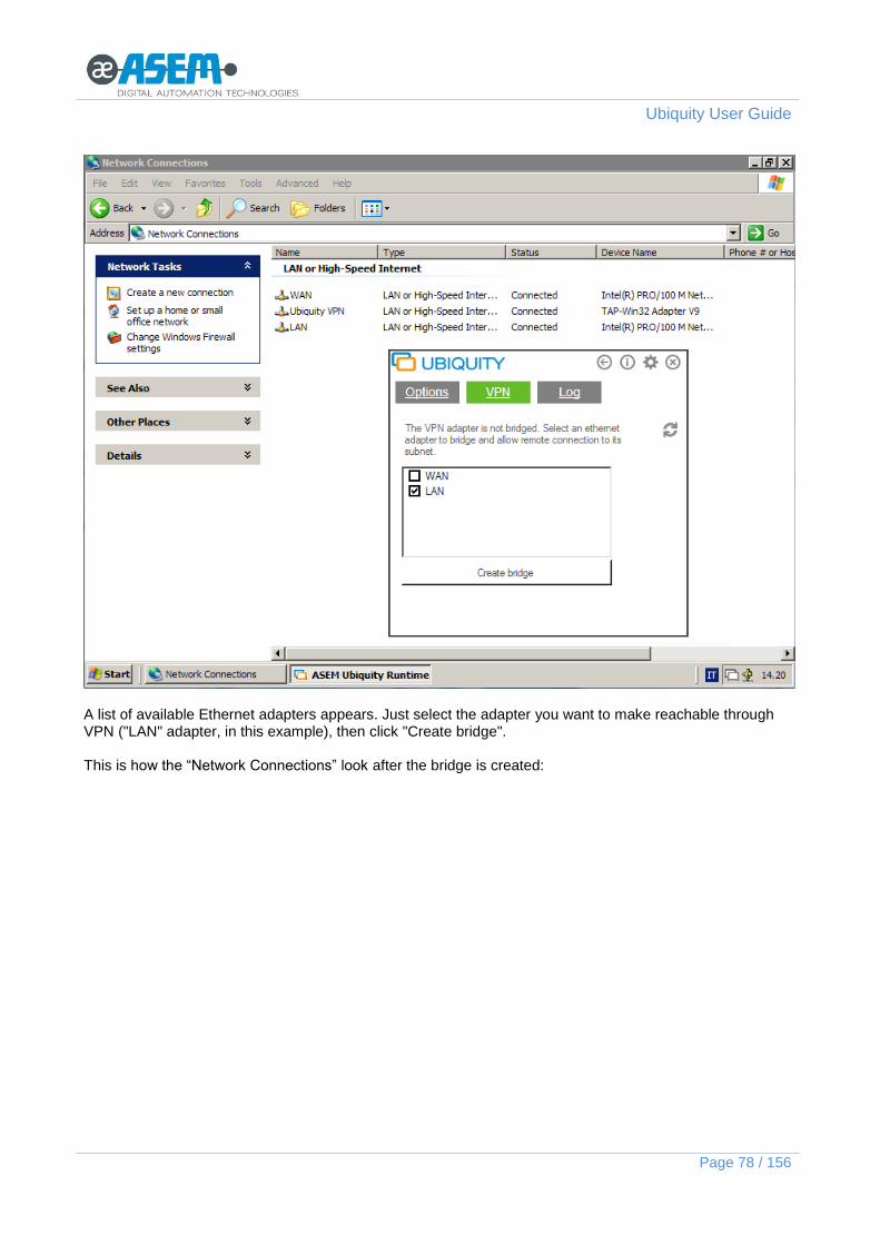
Ubiquity User Guide
Page 78 / 156
A list of available Ethernet adapters appears. Just select the adapter you want to make reachable through VPN ("LAN" adapter, in this example), then click "Create bridge". This is how the “Network Connections” look after the bridge is created:

Ubiquity User Guide
Page 79 / 156
The network bridge appears as a new network adapter that includes the other two adapters ("LAN" and "Ubiquity VPN"). To configure LAN's IP address you should configure the Bridge address itself since "LAN" and "Ubiquity VPN" are no more configurable separately. Ubiquity automatically configures bridge's IP, gateway and DNS, to match the selected adapter's configuration.
The above images are valid for Windows XP on Win32 platforms and for Windows CE where you can use Ubiquity to create the bridge. Windows CE does not provide a user interface from the operating system to create the bridge. This can only be done through the Ubiquity Runtime UI.
If you want to change the IP address (i.e. from 10.20.0.10 to 10.20.0.11), open TCP/IP properties of "Network bridge", and not the adapter you selected for bridging (LAN) properties.
3.4.3 VPN to the entire remote subnet with 1 Ethernet adapter
This connection scenario involves the use of a device running Ubiquity Runtime with a single Ethernet adapter. Using Ubiquity you may want VPN access not only to the remote device, but also to the entire subnet (and automation components) in which the remote device, , is configured. There are two possible scenarios, depending on whether you want to handle
two IP subnets (subnet with Internet access (WAN) and the subnet dedicated to the industrial automation (LAN)), or
a single subnet.

Ubiquity User Guide
Page 80 / 156
A. VPN configuration with two IP subnets
In the example the only physical Ethernet interface is highlighted in blue. A network bridge (yellow) is created to connect the virtual card with the physical one into a single interface. 2 IP addresses are assigned to the network bridge:
one compatible with the remote network and with Internet access (172.17.60.50),
the other belonging to the IP subnet of the Automation network (10.20.0.10). When Control Center connects, the Runtime will assign to the Control Center computer an IP compatible with the automation network (10.20.0.x), in the example 10.20.0.180. Control Center will be able to communicate transparently with TCP and UDP applications, not only with the remote device (10.20.0.10), but also with the connected devices, i.e. the 10.20.0.2 PLC. To create the network bridge, open the Ubiquity Runtime configuration panel, click on the options button (gear icon) and then click the "VPN" button.

Ubiquity User Guide
Page 81 / 156
The single Ethernet adapter will be listed. Select that adapter and then click "Create bridge". The following figure shows the connection status after the bridge has been created.

Ubiquity User Guide
Page 82 / 156
Now you need to configure the Network Bridge's IP address in order to include both the WAN IP (172.17.16.50) and the LAN IP (10.20.0.10).
How to configure Network Bridge’s IP in Windows XP and Windows 7 Open Network bridge's TCP/IP properties and assign the first IP, including the gateway and DNS information, as shown in the figure:

Ubiquity User Guide
Page 83 / 156
Then press the button "Advanced" and then the top left button "Add .." to enter an IP compatible with the automation network.

Ubiquity User Guide
Page 84 / 156
How to configure the Network Bridge’s IP in Windows CE Windows CE does not support multiple IPs configuration by default. In network settings configuration you can only manage a single IP address. Ubiquity Runtime circumvent this limitation by letting you configure multiple addresses in the Ubiquity Runtime control panel. Open Ubiquity Runtime configuration panel, click the options button (gear icon) and click "VPN IPs".

Ubiquity User Guide
Page 85 / 156
Fill "IP" and "Mask" fields and click "Add". Repeat this procedure for the second IP address. Insert the gateway and DNS addresses and click "Apply". Reboot to apply changes. By assigning multiple IP as described, you cannot use the Automatic assignment mode (DHCP). You must then request IP, gateway and DNS to your IT administrator. Alternatively, you can assign a single IP via DHCP, record the assigned IP, gateway and DNS and then re-enter them manually in the IP configuration.
B. VPN configuration with one IP subnet
This case is a simplified version of the previous one. A network bridge has been created between the virtual and the physical Ethernet adapters. The resulting bridge is configured to receive a dynamic address via DHCP or statically with all the information needed to give Internet connectivity to the PC (IP address, gateway and DNS servers).
Since the remote device has a single IP address, it can only communicate with IP addresses within its class (in 172.17.16.x).

Ubiquity User Guide
Page 86 / 156
3.4.4 VPN connection to the remote device only by using physical IP addresses
This is a VPN configuration for Runtime with a Basic license that allows Control Center to connect to the remote device by using the same physical LAN IP subnet, instead of virtual IP addresses. This can be convenient when the supervisor needs to access server applications that bind to the physical IP only. The configuration is the same as topologies 2. or 3., so that the Control Center computer can effectively join the physical LAN subnet, the only limitation due to Runtime Basic license is that only IP traffic to the device IP is encapsulated through the VPN. This scenario is compatible with both licensing models BASIC and PRO.

Ubiquity User Guide
Page 87 / 156
3.4.5 How does Ubiquity handle the IP conflicts?
The use of the VPN connections suggest to consider the possible conflict between the sub networks that you are going to connect. Ubiquity implements the necessary countermeasures to automatically solve any type of conflict. There are two possible cases.
3.4.5.1 The Control Center WAN sub network is the same as the Ubiquity Runtime LAN sub network
The case is automatically solved by using the interface metric property. Ubiquity Control Center sets the metric of the “Ubiquity VPN” virtual adapter to “1” (highest) getting by this way priority over the WAN. In this case, with connected VPN, all the remote IPs are reachable; all the local IP in conflict with remote IPs are masked and they become not reachable. The solution works even in the special case in which the remote IP goes in conflict exactly with the local IP used by the gateway. The proper use of some routing rules makes possible that Control Center stay connected to its gateway and at the same time communicates with the remote IP.
3.4.5.2 The Ubiquity Runtime LAN and WAN sub network are the same
The case is automatically solved by using the interface metric property. Ubiquity Runtime is able to dynamically set the highest priority for the routing rules corresponding to the ALN sub network in compare to the LAN ones. As final result we have that the WAN IPs in conflict with the LAN ones, are automatically made unreachable.
3.4.5.3 PLC IP address and LAN Gateway IP address are the same
If the IP address of the PLC to be reached is the same of the IP address of the gateway in the LAN subnet in which Control Center is present, the conflict is solved taking in consideration that the gateway has to receive messages that are addressed to “external” subnets, while the message to send to the PLC require that the “destination” is an IP address in the subnet. At operative system level, a message addressed to the IP address of the gateway will be readdressed to the Ubiquity VPN interface.
3.5 Runtime command line options
The “Runtime.exe” program can be launched using some command line option. For example, you can assign commands to these actions from an HMI application, to make the presence of Runtime fully transparent.
-connect
Connects "Runtime" to the Ubiquity servers, making it visible to Control Center. You use this option when Runtime is already running but disconnected, because, as default, runtime connects automatically, unless the option -disconnect is not specified.
-disconnect
If Runtime is already running and connected to the servers, this command disconnects it from the servers, making it unavailable to the Control Center. Active remote sessions with Control Centers are dropped while Runtime continues to run. If Runtime is not running, it will start it but it will not connect it to the remote assistance service.
-noui Used only during the first execution of Runtime. It does not create the icon
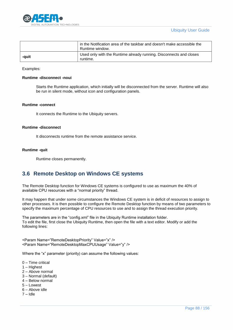
Ubiquity User Guide
Page 88 / 156
in the Notification area of the taskbar and doesn't make accessible the Runtime window.
-quit Used only with the Runtime already running. Disconnects and closes runtime.
Examples: Runtime -disconnect -noui
Starts the Runtime application, which initially will be disconnected from the server. Runtime will also be run in silent mode, without icon and configuration panels.
Runtime -connect
It connects the Runtime to the Ubiquity servers. Runtime -disconnect
It disconnects runtime from the remote assistance service. Runtime -quit
Runtime closes permanently.
3.6 Remote Desktop on Windows CE systems
The Remote Desktop function for Windows CE systems is configured to use as maximum the 40% of available CPU resources with a “normal priority” thread. It may happen that under some circumstances the Windows CE system is in deficit of resources to assign to other processes. It is then possible to configure the Remote Desktop function by means of two parameters to specify the maximum percentage of CPU resources to use and to assign the thread execution priority. The parameters are in the “config.xml” file in the Ubiquity Runtime installation folder. To edit the file, first close the Ubiquity Runtime, then open the file with a text editor. Modify or add the following lines: <Param Name=”RemoteDesktopPriority” Value=”x” /> <Param Name=”RemoteDesktopMaxCPUUsage” Value=”y” /> Where the “x” parameter (priority) can assume the following values: 0 – Time critical 1 – Highest 2 – Above normal 3 – Normal (default) 4 – Below normal 5 – Lowest 6 – Above idle 7 – Idle

Ubiquity User Guide
Page 89 / 156
The “y” parameter (CPU usage) can be any integer number from 1 to 100 to set the maximum percentage of CPU resources assigned to the Remote Desktop thread.
3.7 Execution without Explorer shell
If you run Ubiquity Runtime without the presence of Explorer shell, the Ubiquity icon in the system notification area will not be visible. To access the user interface you can simply run again UbiquityRuntime.exe. A second instance of the runtime will not run, but the user interface will be placed in foreground which allows you to connect and disconnect the access to the network.
3.8 Runtime update
To update Runtime on WCE systems, simply start the update file directly via Control Center during a remote connection to the device. On the “Explorer” form, transfer the Runtime WCE installation file by using the “Send” button as shown in the following figure.
Once the transfer has been completed, start the program on the remote device by pressing the “Execute remotely” button as shown in the following figure.

Ubiquity User Guide
Page 90 / 156
The device will disconnect from the infrastructure while updating. It will be possible to connect to the remote device again at the end of the installation process.
This procedure is valid for WinCE systems and Win32 systems.

Ubiquity User Guide
Page 91 / 156
4 Firewall
The integrated Firewall allows to easily define and apply policies to the VPN traffic in order to improve the security and reduce the traffic between Runtime and Control Center. The configuration procedure is similar to the one used by the commercial Firewall; the initial step is the policy definition, while the final one is the policy application (or use). Ubiquity is featuring a rich pre-defined policies library which is available and maintained at server level and importable within the domain. The firewall policies can be defined locally to any folder and sub folder of the domain and they can be used within the folder where they have be defined. The sub domains can have in fact their own firewall policies applicable to their elements without any interference with the rest of the domain. If there is no need to use different policies in the sub domains, it is a good practice to define all the policies at the root level and use them where needed. To work with the firewall, you need to login to the domain with a user having the “Network security” profile. The policies can be added to the domain in two ways: manual definition and import from server. The commands are shown in the following figure.

Ubiquity User Guide
Page 92 / 156
4.1 Importing the policy
When you click on the import icon you get a window with the list of available policies at the server side.
Once you have identified the desired policy, just select it and click OK to import the policy into the domain.
The policy is shown in the tree as a leaf element at the same level of the folder selected at the moment of the import.
4.2 Custom policy
To define a custom policy, click first on the folder where you need to define the policy and click then on the
policy creation button .

Ubiquity User Guide
Page 93 / 156
You will be asked to provide the name of the policy. Confirm then with OK to create the policy. When you click then on the policy name, you get on the right pane the policy configuration screen where you can insert the rules.
Click now on the “Add” button to introduce a rule in the policy definition. The parameters for the rule definition are:
- MAC address - Ethernet Type
Ubiquity VPN supports the virtualization of the data link layer and hence the integrated firewall supports the definition of rules working on Ethernet types even different from IP. The “Ethernet type” list collects all the protocols commonly used with Ethernet and not only the IP ones on which the common protocols are based. For instance the EtherCAT or the Profinet protocols are not IP protocols and they still appear in the list as configurable protocols.

Ubiquity User Guide
Page 94 / 156
If you select for instance “IP” as Ethernet type, the window is populated according and shows the IP address, the IP protocol and IP port fields.
At each step the window is populated according to the selection made at the previous step until the rule is completely defined.

Ubiquity User Guide
Page 95 / 156
Once completed, the rule is shown in the list.
When a policy is evaluated, you always start from the top to the bottom. The first rule that matches in this order the Ethernet packet in transit makes the policy applicable.
4.3 Policy use (application)
The policy defined or imported can be applied to a folder or to a single device. To apply a policy, first click on the element from the tree view and then open the Firewall section on the right pane.
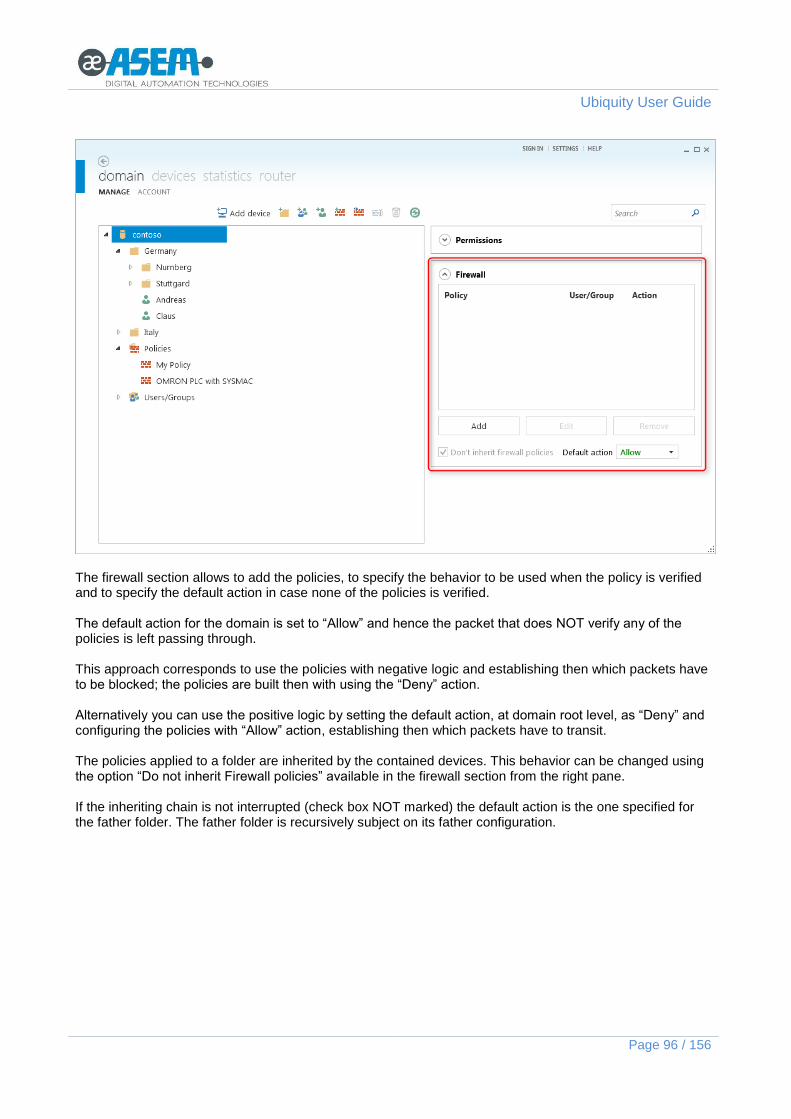
Ubiquity User Guide
Page 96 / 156
The firewall section allows to add the policies, to specify the behavior to be used when the policy is verified and to specify the default action in case none of the policies is verified. The default action for the domain is set to “Allow” and hence the packet that does NOT verify any of the policies is left passing through. This approach corresponds to use the policies with negative logic and establishing then which packets have to be blocked; the policies are built then with using the “Deny” action. Alternatively you can use the positive logic by setting the default action, at domain root level, as “Deny” and configuring the policies with “Allow” action, establishing then which packets have to transit. The policies applied to a folder are inherited by the contained devices. This behavior can be changed using the option “Do not inherit Firewall policies” available in the firewall section from the right pane. If the inheriting chain is not interrupted (check box NOT marked) the default action is the one specified for the father folder. The father folder is recursively subject on its father configuration.

Ubiquity User Guide
Page 97 / 156
To apply a policy to an element, select the folder or the device, display the Firewall section from the right pane and click the “Add” button. Select then the policy from the list of available policies and decide if the policy has to be conditioned to a certain user or group. This allows applying a certain policy to a certain folder or device depending by the connected user. As last step you need to specify the action to be taken in case the evaluated packet matches with the rules of the policy.
When you select any device or folder from the tree view, the firewall section is always showing a summary of all the policies applied, both explicit and inherited.
4.3.1 Example 1: filtering by protocol

Ubiquity User Guide
Page 98 / 156
The example shows how to import a predefined policy and how to apply it to a single device regardless of the user and of the device IP address. Click on the domain icon and click on the “Import policy” button. Select form the list for instance the “Omron PLC with CX Programmer” policy. Once the policy is imported, click on the device to which the policy needs to be applied. We want that during the VPN session the only protocol admitted for the connected sub network, is the “Omron” one for CX Programmer. It will be used to program the PLC which is supposed to be connected to the remote device (HMI or Ubiquity Router). In the “Associate policy” window select then “Allow” as action as shown in the following figure.
Assuming the default action for the domain is “Allow”, you need now to mark the “Do not inherit firewall policies” check box interrupt the inherited behavior. The result is shown in the following figure. All the packets verified by the policy are left passing through; all the packets that do not match the policy will be subject to the default action specified as “Deny” and hence are dropped.
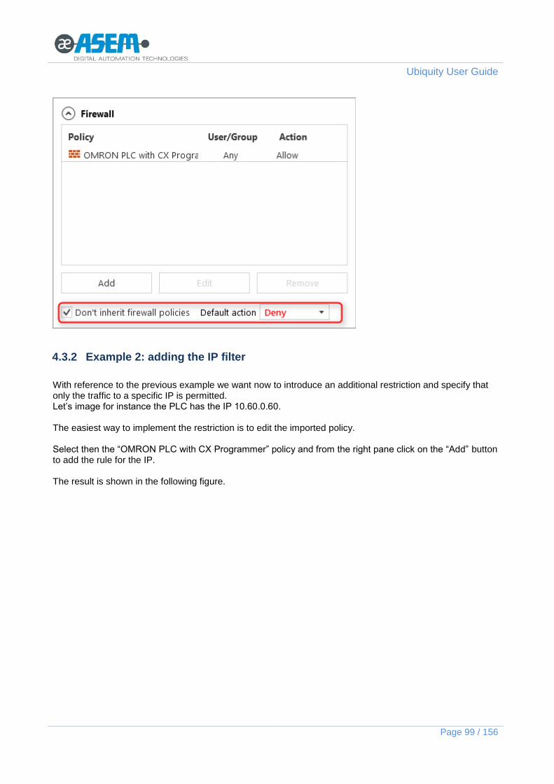
Ubiquity User Guide
Page 99 / 156
4.3.2 Example 2: adding the IP filter
With reference to the previous example we want now to introduce an additional restriction and specify that only the traffic to a specific IP is permitted. Let’s image for instance the PLC has the IP 10.60.0.60. The easiest way to implement the restriction is to edit the imported policy. Select then the “OMRON PLC with CX Programmer” policy and from the right pane click on the “Add” button to add the rule for the IP. The result is shown in the following figure.

Ubiquity User Guide
Page 100 / 156
Because we have modified directly the policy, the change will be immediately active in all the places where the policy has been applied.
4.3.3 Example 3: adding the filter by user or group
With reference to the previous examples we want now that the filter by protocol and IP is active only for the users belonging to a certain group. The filter by user or group is an option of the policy association. Select then the device to which the policy has been applied in the example 1. Display then the Firewall area form the right pane and select the policy. Click now on the “Edit” button to get access to the association properties. From the “Group/User” drop box select then the requested group.

Ubiquity User Guide
Page 101 / 156
The final result is that only the users of the selected group will be able to access to the Omron PLC at the specified IP address. In this connection they can only use the CX programmer protocol.

Ubiquity User Guide
Page 102 / 156
5 Ubiquity Router
Ubiquity Router is a hardware device able to provide the remote assistance services as a standalone solution, allowing to use Ubiquity in all those situations where for any reason the software solution is not an option. Ubiquity Router applies to the automation network with zero impact on the actual devices. No changes are requested to the configuration of any of the existing devices. There are several Ubiquity Router models different for the modem integration for Internet access and support of data monitoring function by means of Premium HMI Runtime. The Router hardware manual provides all the information about installation and commissioning.
Ubiquity RK10 Ubiquity RK11 (internal modem)
Ubiquity RM10 (data monitoring)
Ubiquity RM11 (data monitoring and internal modem)
Ubiquity Router implements a specific variant of Ubiquity Runtime; from the functional point of view this is equivalent to the standard Runtime described in the dedicated chapters.
The Ubiquity Router operating system desktop interface is accessible using the Ubiquity Remote Desktop function, but NO interaction of any type is requested with the Desktop; all the configuration procedures are made using Ubiquity Control Center.
All the general concepts related to the Ubiquity platform stay valid and they can be fully applied to the Router; this is true in particular for the interaction with the Domain, for the user and domain’s permission handling, for the use of the VPN, for the use of the serial pass-through function. Ubiquity Router supports automatic update procedures to provide easy maintenance of the device itself. Please see below a detailed description of the procedures. Ubiquity Router features the following interfaces: 2 Ethernet ports, one for the WAN connection, one for the LAN connection 1 multiple standard and opto-isolated serial port for the “Serial Pass-through” and “MPI Gateway” 1 USB 2.0 Host type port for the configuration and upgrade 2 digital inputs to issue operating commands
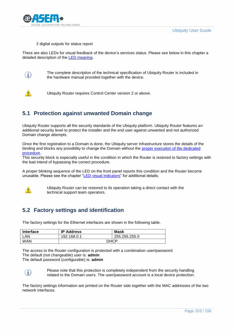
Ubiquity User Guide
Page 103 / 156
2 digital outputs for status report There are also LEDs for visual feedback of the device’s services status. Please see below in this chapter a detailed description of the LED meaning.
The complete description of the technical specification of Ubiquity Router is included in the hardware manual provided together with the device.
Ubiquity Router requires Control Center version 2 or above.
5.1 Protection against unwanted Domain change
Ubiquity Router supports all the security standards of the Ubiquity platform. Ubiquity Router features an additional security level to protect the installer and the end user against unwanted and not authorized Domain change attempts. Once the first registration to a Domain is done, the Ubiquity server infrastructure stores the details of the binding and blocks any possibility to change the Domain without the proper execution of the dedicated procedure. This security block is especially useful in the condition in which the Router is restored to factory settings with the bad intend of bypassing the correct procedure. A proper blinking sequence of the LED on the front panel reports this condition and the Router become unusable. Please see the chapter “LED visual indicators” for additional details.
Ubiquity Router can be restored to its operation taking a direct contact with the technical support team operators.
5.2 Factory settings and identification
The factory settings for the Ethernet interfaces are shown in the following table.
Interface IP Address Mask
LAN 192.168.0.1 255.255.255.0
WAN DHCP
The access to the Router configuration is protected with a combination user/password. The default (not changeable) user is: admin The default password (configurable) is: admin
Please note that this protection is completely independent from the security handling related to the Domain users. The user/password account is a local device protection.
The factory settings information are printed on the Router side together with the MAC addresses of the two network interfaces.

Ubiquity User Guide
Page 104 / 156
5.3 Status and external commands
Ubiquity Router has 6 LEDs on the front panel to provide visual feedback about device status and operation. There are also two digital inputs for external commands and two digital outputs to provide feedback on status and operation.
5.3.1 LED visual feedback
The following figure shows the Router front panel with the LEDs.
The RESET LED is YELLOW. The POWER LED is GREEN The RUN/STOP LED is bicolor VGREEN/RED. The REMOTE CONNECTION LED is GREEN. The COM Rx/COM Tx LEDs are GREEN.
The LED is bicolor GREEN/RED.
The LED is GREEN.
LEDs and are present on Routers with integrated Modem only.
The following behaviors are defined:
- Steady lighted - Blinking - Continuous sequence of a blink codes with a short pause in between to report a status - Single sequence of a blink code to report an event
LED Status Description
RESET Steady lighted Active when pressing the RESET button or when in presence of a not recoverable hardware fault. See also below how this LED is used.
POWER Steady lighted Active when the Router is properly powered.
RUN/STOP Steady Green Ubiquity started and connected to the server.
Steady Red Ubiquity started but NOT connected to the server.
Blinking Green Ubiquity started and connecting to the server.
Blinking Red Ubiquity started but not connected to the server because not associated to any Domain.

Ubiquity User Guide
Page 105 / 156
Sequence of 2 red blinks Connection attempt to a different domain than the first of the initial registration (see the chapter “Protection against unwanted Domain change”).
Single 2 green blinks Configuration from USB stick successfully completed.
Single 2 red blinks User credential for Domain access not valid.
Single 3 green blinks Start and Finish of the router update from USB stick; during the entire update phase the LED is flashing alternatively red and green.
Single 3 red blinks Router updated from USB Stick failed.
Single 4 red blinks Factory restore started.
Single 5 red blinks Ubiquity Runtime execution error, will follow a system restart.
Single 6 red blinks USB stick data format not correct or unknown error.
REMOTE CONNECTION
Steady lighted Active when at least one Control Center client is connected to the Router, otherwise off.
COM Rx COM Tx
Signal presence These LEDs are directly connected to the serial port Rx/Tx signals and they show traffic through the lines.
Steady red The modem has not detected network signal.
Blinking green The modem has detected a weak signal from the network.
Steady green The modem has detected a strong signal from the network.
Blinking red SIM error (e.g. wrong PIN).
Off The modem has not detected the SIM card.
Blinking green Modem currently connected.
Off Modem disconnected.
5.3.2 Commands and Digital I/O
The following figure shows the label on the devise side with the available commands and the terminal assignment.
There are two commands designed for manual activation accessible from two buttons on the upper side of the device.
Ubiquity User Guide
Page 106 / 156
RESET Forces the device restart. The command ensures a complete initialization of all internal electronics and software. The visual feedback of the operation is returned by the RESET LED.
RESTORE FACTORY DEFAULT
Restores the Router to factory settings. All the settings are reset, all the system software is restored to original versions including the operating system, the firmware the Ubiquity Runtime and Domain registrations (identity is removed). To execute the restore, turn off the device, press and hold down the reset button and give power. You need to hold down the button for at least 10 seconds. The starting of the restore process is indicated by the dedicated blink sequence of the LEDs. Wait for the process to be completed and system restart.
There are 2 digital inputs to issue external commands and 2 digital outputs to report the device status via electrical signals. The I/O signal meaning is reported in the following table.
IN0 This input works as “Connection mode”, also referred as “selector key” input. By default the status of this input is ignored. When the Router is configured to handle the input (see “General options” in the Router configuration chapter) it can be used to control from outside the connection to the server. The input can be driven by a mechanical selector, by a key selector or by a PLC outputs.
IN1 This input allows controlling the device restart from outside. The operation corresponds to the RESET button. Once the command is received a proper feedback is returned by the status LED.
OUT0 The output turns active when Ubiquity Router is connected to the associated Domain. Note that the simple connection to the server does not activate the output, it is required that Ubiquity is successfully authenticated to the Domain.
OUT1 The output is active when at least one Control Center client is connected to the Router.
5.4 Ubiquity Router Configuration
Ubiquity Router system software has been designed to reduce as much as possible the user intervention and simplify the few mandatory settings. There are no settings required for the VPN, neither for the bridging of the Ethernet interfaces. All basic settings are made at factory level. No changes are requested to the user. The Ubiquity Router configuration is limited to the network interfaces IP addresses, to the serial port configuration, to the connection mode and Domain registration. Ubiquity Router can be configured in two ways:
Using a network connection
Using a USB stick on which the configuration file has been copied In both cases the configuration is done using Ubiquity Control Center. From Control Center you get access to the Ubiquity Router configuration screen from the icon on the toolbar as shown in the following figure.

Ubiquity User Guide
Page 107 / 156
The configuration process of Ubiquity Router does not require Control Center to be connected to a Domain. In case Control Center is not connected to a Domain some of the configuration options will not be available.
5.4.1 Configuration from network interface
The chapter describes how to configure the Router using a network connection. Turn on the device and connect it to the network from the WAN port. Start Control Center and connect to the Domain to which the Router will have to be associated.
If Control Center is not connected to the Domain it will not possible to associate the Router to the Domain. When doing the first configuration of a Router it is suggested to work with Control Center connected to the desired Domain.
Click then on the “Ubiquity Router” icon on the toolbar and then click on the “Local Area Network” icon as shown in the following figure.

Ubiquity User Guide
Page 108 / 156
The following figure shows the “LAN discovery” screen. Control Center supports the automatic device recognition regardless of the network class on which the PC is configured.
Note that the discovery procedure does not require any Internet connection.

Ubiquity User Guide
Page 109 / 156
Each Ubiquity Router has a local protection against undesired access to its configuration. The protection is made with a combination of user/password. The user is always “admin” (not changeable). The initial password is “admin”; it can be changed later following the procedure described later in this chapter. After you have inserted the password, click the “Discovery” button to start the process. Control Center will populate the “Ubiquity Routers Found” box with the list of devices found in the network with password matching the one specified. Each Router in the list is identified by the MAC addresses of its network interfaces. Click on the line corresponding to the Router you need to configure and then click on the “Configure” button to proceed. The following figure shows the screen with the configuration options.

Ubiquity User Guide
Page 110 / 156
5.4.1.1 WAN Configuration
In this section you can configure the WAN interface used by the Router to get Internet access. The following figure shows the available options. The information shown at the first screen visualization correspond to the actual device parameters values.
The “Obtain IP configuration from DHCP” check box has to be marked in case you need to use the DHCP server for the IP address configuration. In case you need to specify a fixed IP, simply un-mark the check box and fill in the form below.

Ubiquity User Guide
Page 111 / 156
5.4.1.2 LAN Configuration
In this section you can configure the LAN interface parameters. This interface is the one connected to the machine network and it is the network reachable from the VPN. The following figure shows the available options. The information shown at the first screen visualization correspond to the actual device parameters values.
The “Obtain IP configuration from DHCP” check box has to be marked in case you need to use the DHCP server for the interface IP configuration. More common for the LAN interface is to use a fixed IP and in this case, simply un-mark the check box and specify the IP with the mask and click then the “Add” button. The IP will be added to the list.
Please note that the LAN interface support multiple IP. To add an additional IP, simply repeat the above sequence. All the classes corresponding to the added IP/mask couples will be reachable from the VPN.
5.4.1.3 Serial Port Configuration
This section allows to setup the serial port for the serial pass-through.
Click on the combo box to access to the available options. The options are the following:
RS-232C
RS-422
RS-485

Ubiquity User Guide
Page 112 / 156
MPI By selecting “MPI” you setup the Router to work with the MPI gateway function; this allows a pass-through between the Ethernet interface and the MPI controller connected. Please see the chapter “Simatic S7-MPI gateway protocol” for additional information.
5.4.1.4 General Options
This section allows to change the device local password, the connection mode and the Proxy option if needed. The following figure shows the available options.
To change the device password, insert first the actual password and provide the new one. “Availability mode” has four options: Always-on
Digital input SMS Digital input and SMS
When selecting the option “Always-on” the Router will connect to the Domain immediately after power up and when a working internet connection is available; it will also restore the connection if dropped for any reason. When selecting “Digital input” the Router will connect to the configured Domain only and exclusively when the proper electric input (IN0) is activated. If “SMS” is selected, the Router will connect to the configured domain only when an SMS is received from the user. The syntax to be used is:
<Username> <Password> CONNECT – the Modem will connect to the Domain <Username> <Password> DISCONNECT – the Modem will disconnect from the Domain

Ubiquity User Guide
Page 113 / 156
Use the local Router administration credentials, initially printed on the back or changed by means the specific procedure.
After the Router reboot it will be needed to wait for at least three minutes before to send the connection SMS.
When selecting “Digital input and SMS” the Router will connect to the configured Domain only and exclusively when the proper electric input (IN0) is activated and when an SMS is received from the user.
If the electric input is deactivated while the Router is connected, it will be needed to resend the connection SMS.
“Internet connectivity” has three options: Auto
WAN Modem
If “Auto” is selected, the Router will attempt to connect via WAN. If this is not possible, the Router will attempt to connect via WAN. If “WAN” is selected, the Router will attempt to connect via WAN only. If “Modem” is selected, the Router will always attempt to connect via modem.
All wiring information is provided in the hardware manual to which reference should be made.
5.4.1.5 LAN-WAN Routing
This function allows to configure static routing rules between the two Router interfaces (LAN and WAN). Rules for routing single IP addresses or ranges of addresses can be applied. The rules must be applied to the LAN interface and to the WAN interface indicating the addresses concerned by the routing on both interfaces. The following example shows how to route between an IP address in the LAN sub network and an IP address in the WAN sub network.
The first step consists in providing routing instructions between the LAN and WAN interfaces to the Router as shown in the following figure.

Ubiquity User Guide
Page 114 / 156
Set a routing rule on the PC in the WAN to route the packets for the LAN on the Router. Enter the following command on a terminal:
route add 10.20.0.10 mask 255.255.255.255 172.19.17.102 if 11
The parameter after "if" is the network interface number on which to apply the rule. This parameter is shown on the “route print” page (see the following figure).
To check that the rule is set correctly, open a terminal and type “route print”, as shown in the following figure.

Ubiquity User Guide
Page 115 / 156
Alternatively, set the same rule on the WAN gateway device. The last step consists in setting the PLC gateway as IP address of the Router LAN interface.
5.4.1.6 Modem
This section is used to configure the integrated modem parameters.

Ubiquity User Guide
Page 116 / 156
“Status” may assume the following values:
Connected - the modem is connected
Disconnected - the modem is disconnected
Error: <ErrorCode> - one of the following errors was detected: No SIM PIN required PIN2 required PUK required PUK required Wrong PIN Only one PIN insertion retry left NO PIN insertion retry left Modem not present or initialized
Initialization – the Modem is initializing “Carrier mode” shows the technology type used by the radio infrastructure to communicate with the Modem. “Signal strength” is the power of the signal detected by the Modem. The “PIN code” field is used to enter the SIM card PIN code, when required. The “APN” field is used to enter the Access Point Name, required to connect the Modem to the Internet. The “Username”, “Password” and “Domain” fields are used to enter credentials given by the provider to connect the Modem to the Internet. The “Dialed number” field is used to enter the telephone number for the Modem to call in order to connect.
The SIM cannot be removed or replaced while the Router is operating.
The SMS delivery by the Router is handled through the Premium HMI project (see the chapter about Alarm Dispatcher). In order to send SMS the Modem must be properly configured from the Modem section.

Ubiquity User Guide
Page 117 / 156
5.4.1.7 Ubiquity Domain Registration
When configuring the Router via Ethernet the Domain registration is executed by Control Center once Control Center is connected to the Domain on which the Router will be associated. In case Control Center is not connected to any Domain, this option will not be accessible. The following figure shows the configuration options.
Once the check box for identity creation has been marked, specify in the box below the initial name to be assigned to the Router and the path of the Domain folder in which the Router has to be installed.
Please note that a second registration of the same Router on the same Domain is equivalent to a replacement of the identity previously created. This is NOT a simple rename, but a real replacement; all the data and statistics associated with the original registration will be lost.
After a Registration is executed, you can use the “Unregister” following the dedicated procedure. See also the chapter about “Protection against unwanted Domain change”
5.4.1.8 Transferring the configuration to the Router
To transfer the configuration to the Router it is enough to click the “Apply” button at the bottom of the screen. A message will confirm the success of the operation. Depending on the options changed the Router will need to be restarted. If needed the restart is automatically issued by Control Center.
5.4.2 Configuration from USB Stick
The chapter describes how to configure Ubiquity Router by means of a USB Stick without a network connection on which you have stored the configuration file generated by Control Center. The configuration is created in Control Center, exported onto to an XML file used later by Ubiquity Router for the configuration. The file has to be copied on the root folder of the USB Stick used for the configuration. The file can be transferred of course by email and sent to the operator that needs to execute the operation. See below the chapter “Transferring the configuration to the Router” for more information.

Ubiquity User Guide
Page 118 / 156
To execute the Router configuration using the USB Stick, start Control Center and connect to the Domain on which the Router will have to be registered.
If Control Center is not connected to the Domain it will not possible to make the Router association to the Domain. For the first configuration we suggest to start with Control Center connected to the desired Domain.
Click then on the “Ubiquity Router” icon on the toolbar and then click on the “USB” icon as shown in the following figure.
The following screen shows the “Router Login and Identification”. The screen asks for the device local password. Each Ubiquity Router has a local protection against undesired access to its configuration. The protection is made with a combination of user/password. The user is always “admin” (not changeable). The initial password is “admin”; it can be changed later following the procedure described later in this chapter. The configuration made will be usable for any Router with password matching the one specified.

Ubiquity User Guide
Page 119 / 156
Once the password is inserted, click “Next” to continue to the Router Configuration screen as shown in the following figure.

Ubiquity User Guide
Page 120 / 156
Each configuration section shown in the figure above includes a check box called “Export to USB” (see the following figure).
The check box is automatically checked whenever any option in the category is changed; in all cases, it will be up to the user to finally decide whether the configuration made has to be exported or not. Only the checked settings will be exported. The configuration sections are the same as those shown in the Configuration from network interface chapter.
5.4.2.1 Transferring the configuration to the Router
To transfer the configuration to the Router it is enough to click the “Apply” button at the bottom of the screen. In the next screen you will be asked where the XML file with the configuration will be saved. Copy the file to the USB Stick root folder and plug the USB Stick into the Ubiquity Router USB port on the front panel. The Router will automatically recognize the presence of the Stick with the configuration file and will proceed with the configuration. Proper visual feedbacks from the LED will inform about the status of the operation.
5.4.3 Configuration from the web interface
Ubiquity Router can be configured also using a web interface from any browser, including the ones from smart phones and tablet; the access is simply done by typing in the URL address bar the IP address of the

Ubiquity User Guide
Page 121 / 156
router and providing the device credential. The user name is always “admin”, the default password is “admin”, otherwise you need use the one changed in the “General options”. The device with the browser must be configured to access one of the two sub networks of the router (WAN or LAN). The following figure shows the web programming interface from a smart phone with Android operating system.
The web programming interface does not support the domain association neither the removal of the device from the domain.
5.4.4 Simatic S7-MPI Gateway Protocol
The S7-MPI gateway function uses a service which realizes an interface between the Ethernet connection and the serial port. The function allows to reach a controller connected to the Router serial port with MPI protocol, going through the Ethernet interface. The diagram with the principle of operation is shown in the following figure.

Ubiquity User Guide
Page 122 / 156
The Ubiquity Router serial port (COM) is connected to the MPI sub-network on which there are several controller also connected. The gateway protocol drives on one side the serial port with the MPI driver and on its internal side is capable to accept connections from the local Ethernet interface (LAN) and from the VPN connection. When going through the VPN connection you get a direct link from the PC on which Control Center is running and the PLCs. On the Control Center PC is possible then to install the PLC programming software for the PLC management. Later in this chapter you can find the instructions about how to setup the connection.
The Ethernet-MPI gateway function is NOT related to the serial pass-through. The gateway works at Router level and transform an Ethernet data flow into an MPI data flow, and vice versa. The serial pass-through function works instead as a real tunnel between the virtual serial port on the Control Center PC and the physical serial port on the device running Ubiquity Runtime.
When selecting “MPI” in the serial port configuration, you get other two options required to configure the gateway service.
The options are:
MPI Address – MPI address assigned to the Router
Maximum FDL – maximum node ID in the MPI network on which the Router is connect
The information about wiring the Router serial port can be found in the Router hardware manual.

Ubiquity User Guide
Page 123 / 156
Once the VPN connection between the Control Center PC and the LAN network is activated, the PLC programming software can be configured to use Ubiquity Router as communication gateway to connect to the controller.
5.4.4.1 Transferring the PLC program to the PC/PG without network configuration
There is the possibility to execute an upload from the PLC to the PC of the project without the need to make the network configuration as explained in the previous chapter. This of course works if the PLC has been previously programmed with a direct connection. Start the Step 7 program and create a new project. As communication interface make sure you have selected a TCP/IP communication interface as you had to transfer a project via Ethernet.

Ubiquity User Guide
Page 124 / 156
Once the VPN has been activated you will be able to upload the program from the PLC using the command “Load station to PC/PG” The parameters to specify are shown in the figure below. You need to set “via router” as “Destination station” option. It is important then to specify the MPI address and the S7 sub network ID. The IP address is the IP of the LAN interface of the Router.
The sub network ID can be read from the sub network properties as shown in the following figure.

Ubiquity User Guide
Page 125 / 156
5.4.5 Update and restore of Ubiquity Router System Software
Ubiquity Router is an hardware device that works thanks to a set of software components; they can be divided in:
Operating system
Ubiquity Runtime
Firmware The actual versions of the software components are visible in the “Software version“ section accessible at the bottom of the Router Configuration screen when working with Ethernet connection.
All the Ubiquity Router software components can be changed using a very simple procedure, fully automatic, safe and fast. The software components upgrades are distributed in the format of a single file that works as “container” for the components to be replaced. The container files are identified with extension “.asr” (ASEM Software Repository)

Ubiquity User Guide
Page 126 / 156
To execute an update copy the “.asr” file on the root folder of an USB Stick. Plug the USB Stick into the Router USB port and cycle the power. During the power up phase the Router recognize the presence of the USB Stick with the update and it will immediately start the system software update procedure. A proper visual feedback will inform about the status of the operation. No action is requested by the user. The update is completed after the Router is automatically restarted.
5.4.5.1 Router update from remote
As an alternative to the USB update, you can update the Router from remote with a simple file transfer and a restart of the device. First you need the ASR file with the updates desired. Connect to the Router and get the advanced access options. Start the file transfer tool and copy the ASR file to the root of the “MMCMemory” flash disk.
Once the copy has been completed, restart the router by using the Reboot ( ) command available in the “processes” screen. During the reboot the system will recognize the presence of the ASKR file on the root of the “MMCMemory” and proceed automatically to the update. Later the fiel will be deleted and the router restarted once again to finish the upgrade.
The remote update is supported starting from Router version 3.
5.5 Connecting to Ubiquity Router
Once configured Ubiquity Router connects to the network infrastructure publishing its services exactly as it happens with an Ubiquity Runtime. When you click on a tree icon corresponding to a Router, you get on the right pane the “Connect” icon. Because the device does not have a screen, there is no direct link to the Desktop and interactive services.

Ubiquity User Guide
Page 127 / 156
When you click on the “Connect” button, the VPN connection is immediately started.
5.5.1 Router advanced access options
Once the VPN connection has been activated, you can click on the “advanced” link iun the upper part of the window to get access to the advanced options. In the screen are present the following links:
access to the router processes viewer
access to the file transfer tool
access to the Router remote desktop.

Ubiquity User Guide
Page 128 / 156
5.5.2 RMxx Ubiquity Router series support
Ubiquity Control Center support the RMxx Ubiquity Router family which will include the data monitoring function. With the data monitoring the router can be programmed to direct access the connected controller memory and then perform sampling, archiving of data, monitoring of the possible alarm conditions for sending alerts and notifications. Ubiquity Control Center allows an easy way to export the data stored in the local memory of the Router and make accessible the eventual graphical pages through an integrated viewer. All the monitoring capabilities of the Ubiquity RMxx router are programmable in fact with Premium HMI Studio, including synoptic features that will become accessible also through the "Web Client", compatible also with browsers and Premium HMI Mobile Apps. When connecting via Control Center to a Ubiquity Router with data monitor function, the Control Center shown in the top menu bar the shortcuts to get access to the synoptic and to the data logger data for export.

Ubiquity User Guide
Page 129 / 156
From the “web pages” link, you will get the access page to the graphic screen programmed in the HMI project running on the Router. The parameters to provide are the same as the ones requested by a browser or a Premium HMI Mobile through the “Web Client” function of Premium HMI. The graphic pages can be accessed by means of a browser or using the Premium HMI Mobile application without requiring any configuration. The following address must be used in the case of browser: http://<indirizzo_ip_router>/webserver/<synoptic_name>.html The LAN port IP address or the WAN port IP address may be used indifferently.

Ubiquity User Guide
Page 130 / 156
Fill in the fields and click then Connect to display the requested page. When you click on the “datalogger” link you will get the page dedicated to the export of the data eventually archived in the Router internal memory. The archive option must be previously configured in the Premium HMI project deployed to the Router. The Premium HMI project does not require any special settings, except for enabling the historical data recording. Control Center shows a list of all the exportable data.

Ubiquity User Guide
Page 131 / 156

Ubiquity User Guide
Page 132 / 156
6 Appendix
This chapter collects the most common questions asked by users about Ubiquity and its functioning. Please feel free to contact the ASEM technical support staff ([email protected]) for any additional question or doubt you may have on Ubiquity and its use.
6.1 Using Ubiquity Runtime on Siemens Microbox systems
The notes of this chapter should help in setting up a successful connection with Siemens Microbox systems (model tested IPC427C). The information are provided as pure information and the execution of the procedure on the device still remains at full user’s responsibility. The tested configuration is supposed to use two network interfaces referred as LAN1 and LAN2. The hypothesis is to use LAN1 for the machine network and LAN2 for the network connectivity. After the installation of Ubiquity Runtime on the Microbox device, the procedure is the following:
1. Create the bridge between LAN1 and the “Ubiquity VPN” interface 2. Set the IP of the bridge in the correct way, in other words, the IP previously assigned to LAN1 must
be assigned now to the bridge 3. Restart of the PC. After Windows is restarted, select the bridge as communication interface for the
Siemens protocol 4. From the Siemens tool “Station Configuration” remove the component “IE general” 5. Add back again the component “IE general” and be sure to select the new network interface with the
label “… bridge MAC …” At this point you should have Step 7 connectivity both from local and remote.
6.2 About using Ubiquity in combination with Simatic Step 7
6.2.1 Why do the Ubiquity interfaces in the PC/PG interfaces list appear in the Simatic Step 7 software with a warning symbol (yellow triangle)?
The problem can be very likely due to an incorrect update of the interface list after upgrading of the Ubiquity VPN virtual interface driver. To solve the problem simply delete the driver database created by the Step 7 software for each communication interface. Firstly, close the Step 7 software if it is running. The database is located in different positions according to the operating system of the computer where Step 7 is installed. For Windows XP, the database is in the Windows registry. You need then to use the registry editor to locate the following path: HKEY_LOCAL_MACHINE\SOFTWARE\Siemens\SINEC\LogDevices and then delete all the registry keys related to the Ubiquity interfaces in it.

Ubiquity User Guide
Page 133 / 156
It is strongly advised to back up of the registry before starting.
For Windows 7 or Windows 8, the driver database consists of a set of XML files stored in the following path: C:\ProgramData\Siemens\Automation\Simatic OAM\data\LogDevices From that folder you need to remove all the XML files related to the Ubiquity interfaces. Now restart the Step 7 software to automatically recreate the database entries.
6.2.2 Setting the PG/PC interface in Siemens Step 7
This note refers to the use of Siemens Step 7 software in the case the PG/PC interface is set to use the “Auto” mode as shown in the following figure.
With this mode the Step 7 software is able to dynamically assign the IP to the communication interface of the PC in order to communicate with the PLC nodes. For the use with Ubiquity it is suggested to disable this mechanism by selecting the option “Do not assign IP addresses automatically” as shown in the following figure.

Ubiquity User Guide
Page 134 / 156
This automatic mechanism is in fact not needed as Ubiquity already assigns to the Ubiquity VPN adapter a real IP which is compatible with the remote sub network.
6.2.3 Network configuration in Simatic Step 7 NetPro
The use of the MPI gateway service requires a specific network configuration of the Step 7 project. The configuration is executed using the Simatic Step 7 NetPro utility. The network topology is shown in the following figure.

Ubiquity User Guide
Page 135 / 156
The settings required by the PG/PC object are shown in the following figure. The IP address is the one assigned to the PC where the Step 7 software is running.

Ubiquity User Guide
Page 136 / 156
The object named “Ubiquity Router” is a component of “Simatic PC Station” type available in the object folder as shown in the following figure.
NetPro supports default configuration block imports. To assist network setup by users, a configuration block which can be directly imported in the NetPro software has been prepared. The block is called “Asem Ubiquity MPI.cfg” and can be downloaded in the “Support” section of the Ubiquity area on the ASEM web site In NetPro, select “Import” in the “Edit” menu and select the “Asem Ubiquity MPI.cfg” file as shown in the following figure.
The gateway will be imported in the network configuration and will appear as shown in the following figure.

Ubiquity User Guide
Page 137 / 156
Double-click on the green “IE General” box as shown in the figure above to open the Gateway Ethernet interface configuration screen.

Ubiquity User Guide
Page 138 / 156
Note that the “Set MAC address/Use ISO protocol” option must NOT be selected. Enter the IP address of the Ubiquity Router LAN port in the IP address field (in this example: 10.10.0.111). Enter the mask corresponding to the sub network you are configuring in the mask field. Select “Without Router” in the “Gateway” area. Now add a PG/PC station to the network layout using the “Add\Network elements” path. Double-click on the PG/PC station to add an unconnected PG/PC station.

Ubiquity User Guide
Page 139 / 156
Right click on PG/PC and click on “Object properties...”, select the "Interface” form and press “New type…”.

Ubiquity User Guide
Page 140 / 156
Select “Industrial Ethernet” and press OK.
Make sure that “Set MAC address/Use ISO protocol” is not selected on the “Parameters” form (item 2). Set the IP address and the subnet mask assigned to the “Ubiquity VPN” virtual network interface when the VPN connection is established. Check the “Without router” box. In the “Subnet" area in the bottom of the window, select the network to which the “Asem Ubiquity MPI” device is connected. Double-click on OK to close the two Property windows.

Ubiquity User Guide
Page 141 / 156
At this point, the network layout will appear as shown in the following figure.

Ubiquity User Guide
Page 142 / 156
The PG/PC programming interface can now be assigned. To do this, right-click on PG/PC and click on “Assign PG/PC”.
On the “Assign” form of “Unassigned PG/PC interface parameterizations” properties, select the TCP/IP interface which is used to connect to the Ethernet. In particular, the “TCP/IP (Auto) -> Ubiquity Ethernet Adapter” interface must be set to use the Ubiquity service. Then press the “Assign” button and press OK to confirm.

Ubiquity User Guide
Page 143 / 156
The network layout will appear as shown in the following figure.

Ubiquity User Guide
Page 144 / 156
The connection shown in yellow in the PG/PC figure above indicates that this object will be used to access the network. The orange background behind the other objects informs the user that the last changes have not be saved and compiled. The last step is thus to compile and save the network layout of the project. Select “Network\Save and compile...” to do this.
6.3 About using Ubiquity in combination with Simatic TIA Portal
The information in this chapter refers to Simatic TIA Portal v13. The use of the MPI gateway service requires a specific network setup in the Step 7 project. The configuration is done directly using the network tools from TIA portal programming environment. The network topology to implement is shown in the following figure.

Ubiquity User Guide
Page 145 / 156
The key elements of the network topology are the Ubiquity Router and the PC with Control Center. The configuration is required by TIA Portal to know how to reach a device via MPI which is behind a router.
Simatic HMI DO NOT support the programming via MPI when passing through a Router. When working from remote they must be programmed via Ethernet.
The example shown assumes to have an S7-300 PLC to be programmed through an Ubiquity Router using the MPI PLC interface. In our example, we assume the PLC has been already included in the project. The “Device & networks” view will look as shown in the following figure.

Ubiquity User Guide
Page 146 / 156
6.3.1 Configuring the PC with Ubiquity Control Center and Simatic TIA Portal
Open the hardware catalog, locate the “PC Station” component and bring it into the configuration.
Double click on the component, locate the “IE general” interface from the catalog and add it to the first available slot.

Ubiquity User Guide
Page 147 / 156
6.3.2 Configuring the Ubiquity Router component
Insert a new “PC Station” from the catalog, double click on it to access to the configuration, insert in the first slot the “IE General” interface. Locate then then the “CP 5624” interface and insert it in the second available slot.
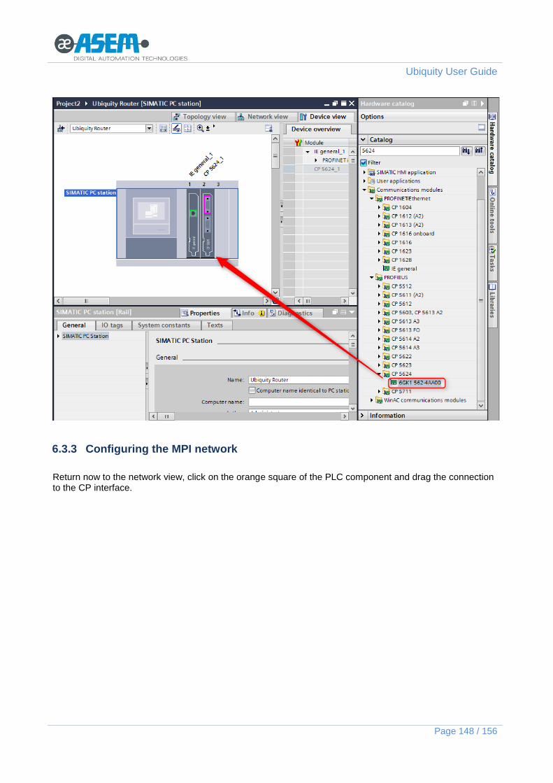
Ubiquity User Guide
Page 148 / 156
6.3.3 Configuring the MPI network
Return now to the network view, click on the orange square of the PLC component and drag the connection to the CP interface.

Ubiquity User Guide
Page 149 / 156
Click on the orang square of the “Ubiquity Router” and assign the MPI node address according with the Router port configuration.
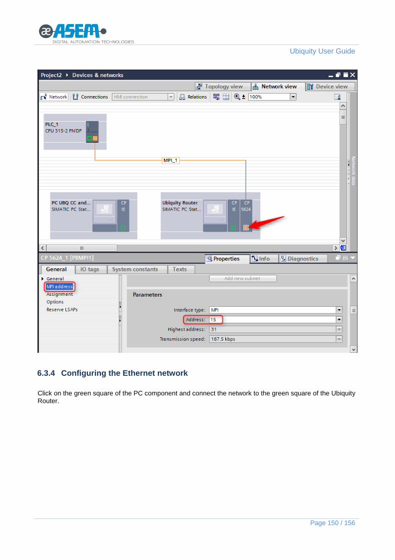
Ubiquity User Guide
Page 150 / 156
6.3.4 Configuring the Ethernet network
Click on the green square of the PC component and connect the network to the green square of the Ubiquity Router.

Ubiquity User Guide
Page 151 / 156
Click on the green square of the Ubiquity Router Ethernet interface ad assign the IP address of the LAN port of the Router.

Ubiquity User Guide
Page 152 / 156
Click now on the green square of the Ubiquity Control Center PC and assign to the Ethernet port the IP acquired by the Ubiquity Ethernet adapter during the VPN session.
6.4 About using Ubiquity in combination with Hilscher gateways
This chapter explains how to use the NL50-MPI/NT50-MPI gateway from Hilscher in combination with Ubiquity on an HMI30 device. The information reported refers to the use of the version 1.54 of the IBH Hilscher. The NL50-MPI / NT50-MPI gateway must per powered and connected to the network interface of the panel. The following figure shows the hardware setup.

Ubiquity User Guide
Page 153 / 156
From the Hilscher web site (http://www.ibhsoftec.com) is possible to get drivers updates. The 1.54 driver can be downloaded from the following link: http://download.ibhsoftec.com/neutral/IBHNet154Setup.exe
Install the driver of the gateway on the PC where you have Ubiquity Control Center and restart the PC. Start the Step 7 software and select the PG/PC Interface properties. Create then a “new station“ according to the instruction shown in the following figure.

Ubiquity User Guide
Page 154 / 156
Give a name to the Station, insert an IP address to be assigned to the gateway, select the profile to use between MPI, Profibus or PPI and select the “IBH Link S7 / IBH Link S7 ++” option. You may also increase the timeout to higher values.

Ubiquity User Guide
Page 155 / 156
Starts now Ubiquity and activate the VPN connection with the device running Ubiquity Runtime to which the Hilscher gateway is connected. From the “Multiple network card detected” dialog select the Ubiquity Ethernet Adapter.
The network scan operation shall return the connected gateway as available. Select it and click “Settings” In case the Hilscher gateway has been never configured before, you will need to assign to it a valid IP address as shown in the following figures.
Note the IP just assigned is not yet permanent and it will be lost in case of power cycle of the gateway.

Ubiquity User Guide
Page 156 / 156
From the “Settings” dialog you will need to assign now the complete network configuration of the gateway.
In the MPI/Profibus tab the settings must be the following:
Communication speed: Baudrate.
Own device Address: MPI/PPI/Profibus address to be assigned to the gateway port. This address node must be of course unique in the network.
Maximum device address: highest node number in the MPI/Profibus/PPI network.
Bus Profile: MPI/PPI o Profibus. Once the settings are completed, you can now save them permanently with the proper command “Save permanently”.