Utilization of Direct Metal Laser Sintering in Injection ... · Utilization of Direct Metal Laser...
6
Utilization of Direct Metal Laser Sintering in Injection Mold Design JAN NAVRATIL, MICHAL STANEK, STEPAN SANDA, MIROSLAV MANAS, DAVID MANAS, ALES MIZERA, MARTIN BEDNARIK Tomas Bata University in Zlin nam. T. G. Masaryka 5555, 760 01 Zlin CZECH REPUBLIC [email protected] http://www.ft.utb.cz Abstract: - The aim of this research paper is to design two variants of cooling systems (cavities) for an injection mold. Both systems are designed to be used on the same injection mold for producing the same product. The difference is in the manufacturing technology itself. The first variant was made by conventional methods of machining and the second variant was made by combination of conventional methods and unconventional rapid prototyping technology Direct Metal Laser Sintering (DMLS). It was dealt with design of the universal injection mold frame and both cooling systems for an existing product in the first part of this research paper. In the second part were both designs compared by mechanical analysis and their influence on final product by flow analysis. Last part is focused on economical evaluation of both designs. Key-Words: - Rapid Prototyping, Direct Metal Laser Sintering, Injection Molding, Analysis, Mold, Part 1 Introduction Rapid prototyping belongs among modern manufacturing technologies, where the resulting product is made by adding material layer-by-layer, unlike subtracting technologies (milling and drilling), where the resulting product is made by removing material [1-3, 13-19]. Fig.1 Manufacturing technologies There are several rapid prototyping technologies based on the adding material, the main differences are in a used material and product building technologies. Between this technologies belong, for example; stereolithography (SL), laminated object manufacturing (LOM), fused deposition modeling (FDM), selective laser sintering (SLS) and direct metal laser sintering (DMLS) [4-15]. All these technologies are based on creation of real product directly from 3D CAD data in a few hours; this results in speeding up process planning and tooling design, because of possibility to provide a real product at an earlier design stage [1, 4, 5, 21]. Laser sintering is one of the leading commercial processes for rapid fabrication of functional prototypes and tools. The process creates solid three-dimensional objects by bonding powdered materials using laser energy [6, 23, 24]. Direct metal laser sintering (DMLS) allows creating fully functional metal part without using any tools and without any shape restrictions. The parts produced by this technology have mechanical properties fully comparable with cast or machined parts. Benefits of this technology increases with shape complexity; that means the more complex part, the more economical the process becomes [9- 11, 17-23]. Principle of this technology is based on melting very thin layers of metal powder. The process begins by applying first layer onto a steel platform and melting required contour. Then is another layer applied and process continuous until the whole part is made. Minimal thickness of each layer is 20 µm. It is also necessary to use supporting structure, which is applied simultaneously with base material. The supports are necessary because the powder itself is not sufficient enough to hold in place the liquid phase created by melting required contour [11, 16-22]. Once the part is created then it goes through some finishing operations including support removal, shot peening and polishing. Between advantages belong besides shape complexity and Recent Researches in Circuits and Systems ISBN: 978-1-61804-108-1 273
Transcript of Utilization of Direct Metal Laser Sintering in Injection ... · Utilization of Direct Metal Laser...

Utilization of Direct Metal Laser Sintering in Injection Mold Design
JAN NAVRATIL, MICHAL STANEK, STEPAN SANDA, MIROSLAV MANAS,
DAVID MANAS, ALES MIZERA, MARTIN BEDNARIK
Tomas Bata University in Zlin
nam. T. G. Masaryka 5555, 760 01 Zlin
CZECH REPUBLIC
[email protected] http://www.ft.utb.cz
Abstract: - The aim of this research paper is to design two variants of cooling systems (cavities) for an injection
mold. Both systems are designed to be used on the same injection mold for producing the same product. The
difference is in the manufacturing technology itself. The first variant was made by conventional methods of
machining and the second variant was made by combination of conventional methods and unconventional rapid
prototyping technology Direct Metal Laser Sintering (DMLS). It was dealt with design of the universal
injection mold frame and both cooling systems for an existing product in the first part of this research paper. In
the second part were both designs compared by mechanical analysis and their influence on final product by
flow analysis. Last part is focused on economical evaluation of both designs.
Key-Words: - Rapid Prototyping, Direct Metal Laser Sintering, Injection Molding, Analysis, Mold, Part
1 Introduction Rapid prototyping belongs among modern
manufacturing technologies, where the resulting
product is made by adding material layer-by-layer,
unlike subtracting technologies (milling and
drilling), where the resulting product is made by
removing material [1-3, 13-19].
Fig.1 Manufacturing technologies
There are several rapid prototyping technologies
based on the adding material, the main differences
are in a used material and product building
technologies. Between this technologies belong, for
example; stereolithography (SL), laminated object
manufacturing (LOM), fused deposition modeling
(FDM), selective laser sintering (SLS) and direct
metal laser sintering (DMLS) [4-15]. All these
technologies are based on creation of real product
directly from 3D CAD data in a few hours; this
results in speeding up process planning and tooling
design, because of possibility to provide a real
product at an earlier design stage [1, 4, 5, 21].
Laser sintering is one of the leading commercial
processes for rapid fabrication of functional
prototypes and tools. The process creates solid
three-dimensional objects by bonding powdered
materials using laser energy [6, 23, 24].
Direct metal laser sintering (DMLS) allows
creating fully functional metal part without using
any tools and without any shape restrictions. The
parts produced by this technology have mechanical
properties fully comparable with cast or machined
parts. Benefits of this technology increases with
shape complexity; that means the more complex
part, the more economical the process becomes [9-
11, 17-23].
Principle of this technology is based on melting
very thin layers of metal powder. The process
begins by applying first layer onto a steel platform
and melting required contour. Then is another layer
applied and process continuous until the whole part
is made. Minimal thickness of each layer is 20 µm.
It is also necessary to use supporting structure,
which is applied simultaneously with base material.
The supports are necessary because the powder
itself is not sufficient enough to hold in place the
liquid phase created by melting required contour
[11, 16-22].
Once the part is created then it goes through
some finishing operations including support
removal, shot peening and polishing. Between
advantages belong besides shape complexity and
Recent Researches in Circuits and Systems
ISBN: 978-1-61804-108-1 273

cost and time savings also possibility of recyclation
of about 98% of not used powder. It also has some
disadvantages such as limited working space, high
acquisition costs and high porosity [11-12, 25].
2 Design Child seat was chosen as a sample of the injected
part. This product was chosen because it is
complicated enough to use Direct Metal Laser
Sintering technology. Its basic dimensions are
359*399*374 mm (height*width*depth).
Fig.2 Injected part
2.1 Material Polypropylene was chosen as a product material due
to its advantageous combination of processing
properties, high stiffness, low price and availability.
For analysis purposes was an actual polypropylene
chosen, its trademark is Daplen BH 345 MO and the
supplier is Borealis company. Its basic properties
can be seen in table 1.
Table 1 Material properties
MATERIAL PROPERTY VALUE
Elastic modulus E [MPa] 1340
Shear modulus G [MPa] 481.3
Melt flow index MFI [g/10min] 45
Shrinkage [%] 1.34
Hardness [HRC – R-scale] 89
2.2 Injection Mold Design of injection mold was made in consideration
of interchangeability, this means that can be, for
example; unconventionally manufactured cavity
used together with conventionally manufactured
core without any change in injection mold, however;
comparison was carried out only with standard
organization – conventional versus unconventional
cavities organization.
The injection mold itself was specifically designed
due to the shape of injected product, where could
not be neither ejector nor gate traces visible on the
exposed side. Therefore injection and ejection
systems are on the same side – in this case on the
right. Hot injection system with three hot nozzles
was chosen to carry out an injection of melted
polymer. Ejection was carried out by eight standard
ejection pins and control of this system was
implemented by four external hydraulic pullers.
Partially original parts and partially HASCO
standards were used for designing whole mold.
Fig.3 Injection mold – left side
Fig.4 Injection mold – right side
Recent Researches in Circuits and Systems
ISBN: 978-1-61804-108-1 274
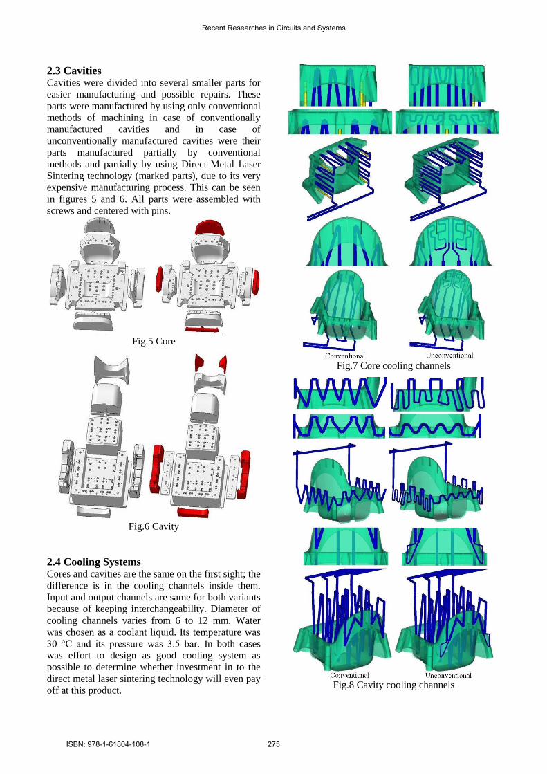
2.3 Cavities Cavities were divided into several smaller parts for
easier manufacturing and possible repairs. These
parts were manufactured by using only conventional
methods of machining in case of conventionally
manufactured cavities and in case of
unconventionally manufactured cavities were their
parts manufactured partially by conventional
methods and partially by using Direct Metal Laser
Sintering technology (marked parts), due to its very
expensive manufacturing process. This can be seen
in figures 5 and 6. All parts were assembled with
screws and centered with pins.
Fig.5 Core
Fig.6 Cavity
2.4 Cooling Systems Cores and cavities are the same on the first sight; the
difference is in the cooling channels inside them.
Input and output channels are same for both variants
because of keeping interchangeability. Diameter of
cooling channels varies from 6 to 12 mm. Water
was chosen as a coolant liquid. Its temperature was
30 °C and its pressure was 3.5 bar. In both cases
was effort to design as good cooling system as
possible to determine whether investment in to the
direct metal laser sintering technology will even pay
off at this product.
Fig.7 Core cooling channels
Fig.8 Cavity cooling channels
Recent Researches in Circuits and Systems
ISBN: 978-1-61804-108-1 275
As can be seen from figures 7 and 8 most of the
channels are completely the same for both variants
and only at the most problematic areas was the
direct metal laser sintering technology used for
creation more complex cooling channels. This
should also result in significant cost savings.
3 Analysis Flow and mechanical analysis was done to compare
both variants.
3.1 Flow Analysis This analysis was done in Autodesk Moldflow
Insight 2011 under same process parameters, which
can be seen in table 2.
Table 2 Process parameters
PROCESS PARAMETERS VALUE
Mold surface temperature [°C] 35
Melt temperature [°C] 200
Mold-open time [s] 5
Coolant temperature [°C] 30
Coolant pressure [bar] 3.5
Ejection temperature [°C] 115
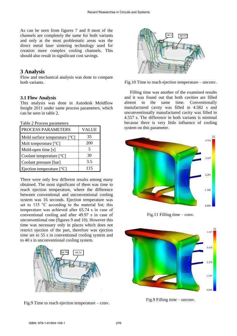
There were only few different results among many
obtained. The most significant of them was time to
reach ejection temperature, where the difference
between conventional and unconventional cooling
system was 16 seconds. Ejection temperature was
set to 115 °C according to the material list; this
temperature was achieved after 65.74 s in case of
conventional cooling and after 49.97 s in case of
unconventional one (figures 9 and 10). However this
time was necessary only in places which does not
restrict ejection of the part, therefore was ejection
time set to 55 s in conventional cooling system and
to 40 s in unconventional cooling system.
Fig.9 Time to reach ejection temperature – conv.
Fig.10 Time to reach ejection temperature – unconv.
Filling time was another of the examined results
and it was found out that both cavities are filled
almost in the same time. Conventionally
manufactured cavity was filled in 4.582 s and
unconventionally manufactured cavity was filled in
4.557 s. The difference in both variants is minimal
because there is very little influence of cooling
system on this parameter.
Fig.11 Filling time – conv.
Fig.9 Filling time – unconv.
Recent Researches in Circuits and Systems
ISBN: 978-1-61804-108-1 276

3.2 Mechanical analysis Mechanical analysis was done in Catia V5R18 only
at one cavity which was chosen core. Investigated
injection pressure was approximately 47 MPa in
both cases, but loading pressure was increased by
safety coefficient to 50 MPa. For analysis purposes
were both cavities clamped exactly the same like in
the injection mold frame.
Calculated von Misses stress was 502 MPa in
case of conventionally manufactured core and 817
MPa in case of unconventionally manufactured core
(figures 13 and 14). Despite higher stress in the
second case the safe stress (1267 MPa) was not
exceeded, therefore both variants comply.
Fig.13 Von misses stress – conv.
Fig.14 Von misses stress – unconv.
4 Economical evaluation
Economical evaluation was done according to the
pricing of the manufacturing process of both
variants, furthermore according to fixed costs and
cycle length (table 3).
Table 3 Costs
Figure 15 shows that despite higher investment
costs to the direct metal laser sintering technology;
it will be paid off after 73512 cycles due to a shorter
injection molding cycle. This means that this variant
will be better choice if the planned production is
higher than 73512 cycles.
Fig.15 Cost comparison
5 Conclusion In this research paper were designed injection mold
and two types of cavities for one injected product –
child seat. Both cavities were compared from flow
and mechanical points of view and economically
evaluated at the end.
Investigation of flow analysis results showed that
both variants are equally suitable for chosen injected
product, because the only significant difference was
shorter injection molding cycle at unconventionally
manufactured cavities. Mechanical analysis showed
that both variants comply because neither of
variants exceeded allowed von misses stress.
Economical evaluation showed that using
unconventional variant is eligible only for higher
productions.
Acknowledgement:
This paper is supported by the internal grant of TBU
in Zlin No. IGA/FT/2012/041 funded from the
resources of specific university research and by the
European Regional Development Fund under the
project CEBIA-Tech No. CZ.1.05/2.1.00/03.0089.
Recent Researches in Circuits and Systems
ISBN: 978-1-61804-108-1 277

References:
[1] Yu Zhang, Hongwu Liu, Application of Rapid
Prototyping Technology in Die Making of
Diesel Engine, Tsinghua Science &
Technology, Vol.14, 2009, pp. 127-131.
[2] S.H. Choi, S. Samavedam, Modelling and
Optimisation of Rapid Prototyping, Computers
in Industry, Vol.47, 2002, pp. 39-53.
[3] C.K. Chua et al., Rapid Prototyping: Principles
and Applications, World Scientific Publishing
Co. Pte. Ltd., 2010
[4] Xue Yan, P. Gu, A Review of Rapid
Prototyping Technologies and Systems,
Computer-Aided-Design, Vol.28, 1996, pp.
307-318.
[5] D.T.Pham, R.S. Gault, A Comparison of Rapid
Prototyping Technologies, International
Journal of Machine Tools and Manufacture,
Vol.38, 1998, pp. 1257-1287.
[6] A. Simchi, Direct Laser Sintering of Metal
Powders: Mechanism, Kinetics and
Microstructural Features, Materials Science
and Engineering, Vol.428, 2006, pp. 148-158.
[7] J.-P. Kruth et al., Progress in Additive
Manufacturing and Rapid Prototyping, CIRP
Annals – Manufacturing Technology, Vol.47,
1998, pp. 525-540.
[8] Yongnian Yan et al., Rapid Prototyping and
Manufacturing Technology: Principle,
Representative Technics, Applications and
Development Trends, Tsinghua Science &
Technology, Vol.14, 2009, pp. 1-12.
[9] M.W. Khaing et al., Direct Metal Laser
Sintering for Rapid Tooling: Processing and
Characterisation of EOS Parts, Journal of
Materials Processing Technology, Vol.113,
2001, pp. 269-272.
[10] A. Simchi et al., On the Development of Direct
Metal Laser Sintering for Rapid Tooling,
Journal of Materials Processing Technology,
Vol.141, 2003, pp. 319-328.
[11] Jouni Hänninen, Direct Metal Laser Sintering,
Advanced Materials & Processes, Vol.160,
2002, pp. 33-36.
[12] M. Stanek et al., Optimization of Injection
molding process, International Journal of
Mathematics and Computers in Simulation,
Vol.5, 2011, pp. 413-421.
[13] M. Stanek et al., Simulation of Injection
Molding Process by Cadmould Rubber,
International Journal of Mathematics and
Computers in Simulation, Vol.5, 2011, pp. 422-
429.
[14] D. Manas et al., Thermal Effects on Steels at
Different Methods of Separation, Chemicke
Listy, Vol.105, 2011, pp. 713-715.
[15] M. Manas et al., Improvement of Mechanical
Properties of the TPE by Irradiation, Chemicke
Listy, Vol.105, 2011, pp. 828-829.
[16] J. Javorik et al., The Shape Optimization of the
Pneumatic Valve Diaphragms, International
Journal of Mathematics and Computers in
Simulation, Vol.5, 2011, pp. 361-369.
[17] M. Stanek et al., Influence of Surface
Roughness on Fluidity of Thermoplastics
Materials, Chemicke Listy, Vol.103, 2009, pp.
91-95.
[18] D. Manas et al., Influence of Mechanical
Properties on Wear of Heavily Stressed Rubber
Parts, KGK – Kautschuk Gummi Kunststoffe,
Vol.62, 2009, pp. 240-245.
[19] M. Manas et al., Modification of Polyamides
Properties by Irradiation, Chemicke Listy,
Vol.103, 2009, pp. 24-26.
[20] D. Manas et al., Wear of Multipurpose Tire
Treads, Chemicke Listy, Vol.103, 2009, pp. 72-
74.
[21] S. Sanda et al., Injection Mold Cooling System
by DMLS, Chemicke Listy, Vol.103, 2009, pp.
140-142.
[22] M. Stanek et al., Plastics Parts Design
Supported by Reverse Engineering and Rapid
Prototyping, Chemicke Listy, Vol.103, 2009,
pp. 88-91.
[23] S. Sanda et al., Gate Effect on Quality of
Injected Part, Chemicke Listy, Vol.105, 2011,
pp. 301-303.
[24] M. Stanek et al., How the Filler Influence the
Fluidity of Polymer, Chemicke Listy, Vol.105,
2011, pp. 303-305.
[25] K. Kyas et al., Simulation of Rubber Injection
Molding Process, Chemicke Listy, Vol.105,
2011, pp. 354-356.
[26] O. Suba, L. Sykorova, S. Sanda, M. Stanek
“Modelling of Thermal Stresses in Printed
Circuit Boards”, in Proc. 13th WSEAS
International Conference on Automatic
Control, Modelling & Simulation, Lanzarote,
Canary Islands, 2011, p.173-175.
[27] O. Suba, L. Sykorova, S. Sanda, M. Stanek,
“Stress – State Modelling of Injection-molded
Cylindrical Bosses Reinforced with Short
Fibres”, in Proc. 13th WSEAS International
Conference on Automatic Control, Modelling
& Simulation, Lanzarote, Canary Islands, 2011,
p.177-179.
Recent Researches in Circuits and Systems
ISBN: 978-1-61804-108-1 278