UT4 and UT4-22 Cable Pulling Systems -...
20
INSTRUCTION MANUAL UT4 and UT4-22 Cable Pulling Systems Serial Code AMJ 52041928 REV 5 © 2010 Greenlee Textron Inc. 6/10 Read and understand all of the instructions and safety information in this manual before operating or servicing this tool. Register this product at www.greenlee.com
Transcript of UT4 and UT4-22 Cable Pulling Systems -...
INSTRUCTION MANUAL
UT4 and UT4-22Cable Pulling Systems
Serial Code AMJ
52041928 REV 5 © 2010 Greenlee Textron Inc. 6/10
Read and understand all of the instructions and safety information in this manual before operating or servicing this tool.
Register this product at www.greenlee.com
UT4 and UT4-22 Cable Pulling Systems
Greenlee / A Textron Company 4455 Boeing Dr. • Rockford, IL 61109-2988 USA • 815-397-70702
Description
The Greenlee UT4 and UT4-22 Cable Pulling Systems are intended to pull cable through conduit for medium-duty applications. Typical applications might be: pulling 3x500 kcmil (mcm) cables 300 feet or 3x3/0 cables 600 feet.
Safety
Safety is essential in the use and maintenance of Greenlee tools and equipment. This manual and any markings on the tool provide information for avoiding hazards and unsafe practices related to the use of this tool. Observe all of the safety information provided.
Purpose of this Manual
This manual is intended to familiarize all personnel with the safe operation and maintenance procedures for the following Greenlee tools:
UT4 Cable Pulling System
UT4-22 Cable Pulling System
Keep this manual available to all personnel.
Replacement manuals are available upon request at no charge at www.greenlee.com.
All specifications are nominal and may change as design improvements occur. Greenlee Textron Inc. shall not be liable for damages resulting from misapplication or misuse of its products.
KEEP THIS MANUAL
Table of Contents
Description .................................................................... 2
Safety ............................................................................ 2
Purpose of this Manual ................................................. 2
Important Safety Information ..................................... 3-5
Specifications ................................................................ 6
Initial Assembly ............................................................. 7
Assembly ....................................................................... 8
Setup
Up-pull ................................................................. 9-10
Down-pull ................................................................ 11
Floor Mount ............................................................. 12
Operation ................................................................ 13-14
Maintenance ................................................................ 15
Illustrations and Parts Lists .................................... 16-19
UT4 and UT4-22 Cable Pulling Systems
Greenlee / A Textron Company 4455 Boeing Dr. • Rockford, IL 61109-2988 USA • 815-397-70703
IMPORTANT SAFETY INFORMATION
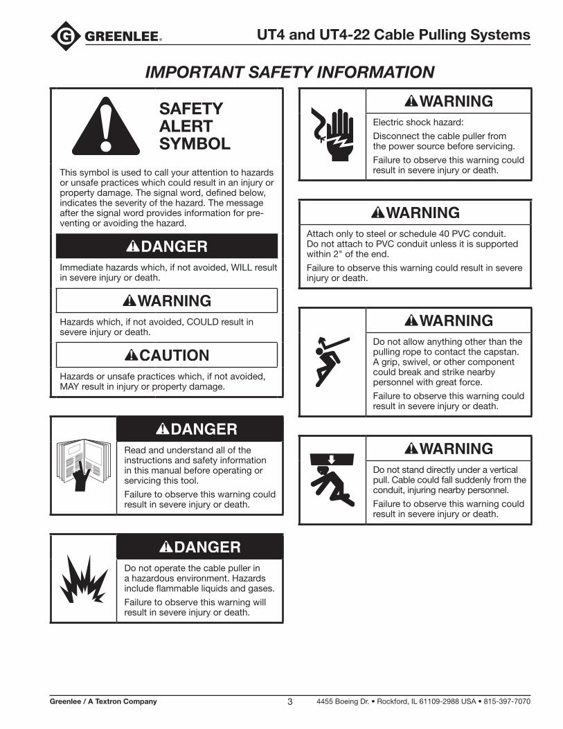
SAFETY ALERT SYMBOL
This symbol is used to call your attention to hazards or unsafe practices which could result in an injury or property damage. The signal word, defined below, indicates the severity of the hazard. The message after the signal word provides information for pre-venting or avoiding the hazard.
Immediate hazards which, if not avoided, WILL result in severe injury or death.
Hazards which, if not avoided, COULD result in severe injury or death.
Hazards or unsafe practices which, if not avoided, MAY result in injury or property damage.
Read and understand all of the instructions and safety information in this manual before operating or servicing this tool.
Failure to observe this warning could result in severe injury or death.
Do not operate the cable puller in a hazardous environment. Hazards include flammable liquids and gases.
Failure to observe this warning will result in severe injury or death.
Electric shock hazard:
Disconnect the cable puller from the power source before servicing.
Failure to observe this warning could result in severe injury or death.
Attach only to steel or schedule 40 PVC conduit. Do not attach to PVC conduit unless it is supported within 2" of the end.
Failure to observe this warning could result in severe injury or death.
Do not allow anything other than the pulling rope to contact the capstan. A grip, swivel, or other component could break and strike nearby personnel with great force.
Failure to observe this warning could result in severe injury or death.
Do not stand directly under a vertical pull. Cable could fall suddenly from the conduit, injuring nearby personnel.
Failure to observe this warning could result in severe injury or death.
UT4 and UT4-22 Cable Pulling Systems
Greenlee / A Textron Company 4455 Boeing Dr. • Rockford, IL 61109-2988 USA • 815-397-70704
IMPORTANT SAFETY INFORMATION
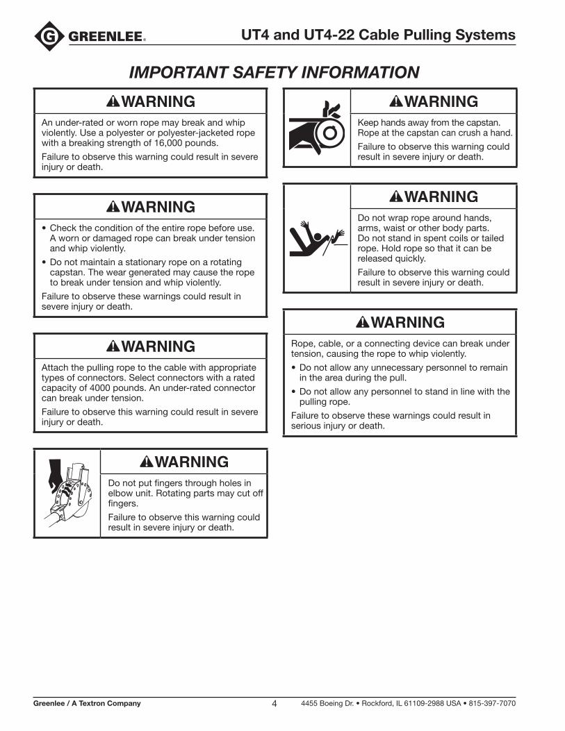
An under-rated or worn rope may break and whip violently. Use a polyester or polyester-jacketed rope with a breaking strength of 16,000 pounds.
Failure to observe this warning could result in severe injury or death.
• Check the condition of the entire rope before use. A worn or damaged rope can break under tension and whip violently.
• Do not maintain a stationary rope on a rotating capstan. The wear generated may cause the rope to break under tension and whip violently.
Failure to observe these warnings could result in severe injury or death.
Attach the pulling rope to the cable with appropriate types of connectors. Select connectors with a rated capacity of 4000 pounds. An under-rated connector can break under tension.
Failure to observe this warning could result in severe injury or death.
Do not put fingers through holes in elbow unit. Rotating parts may cut off fingers.
Failure to observe this warning could result in severe injury or death.
Keep hands away from the capstan. Rope at the capstan can crush a hand.
Failure to observe this warning could result in severe injury or death.
Do not wrap rope around hands, arms, waist or other body parts. Do not stand in spent coils or tailed rope. Hold rope so that it can be released quickly.
Failure to observe this warning could result in severe injury or death.
Rope, cable, or a connecting device can break under tension, causing the rope to whip violently.
• Do not allow any unnecessary personnel to remain in the area during the pull.
• Do not allow any personnel to stand in line with the pulling rope.
Failure to observe these warnings could result in serious injury or death.
UT4 and UT4-22 Cable Pulling Systems
Greenlee / A Textron Company 4455 Boeing Dr. • Rockford, IL 61109-2988 USA • 815-397-70705
IMPORTANT SAFETY INFORMATION
Do not allow the rope to overlap on the capstan. If the rope approaches the top of the angled part of the capstan, relax the tailing force. If an overlap does occur, shut off the puller immediately.
Failure to observe this warning could result in severe injury or death.
Use this tool for manufacturer’s intended purpose only. Do not use the cable puller as a hoist or winch.
• The cable puller cannot lower a load.
• The load may fall.
Failure to observe this warning could result in severe injury or death.
Entanglement hazard:
• Do not operate the cable puller while wearing loose-fitting clothing.
• Retain long hair.
Failure to observe these warnings could result in severe injury or death.
Wear eye protection when using this tool.
Failure to wear eye protection could result in severe eye injury from flying debris.
UT4 and UT4-22 Cable Pulling Systems
Greenlee / A Textron Company 4455 Boeing Dr. • Rockford, IL 61109-2988 USA • 815-397-70706
Specifications
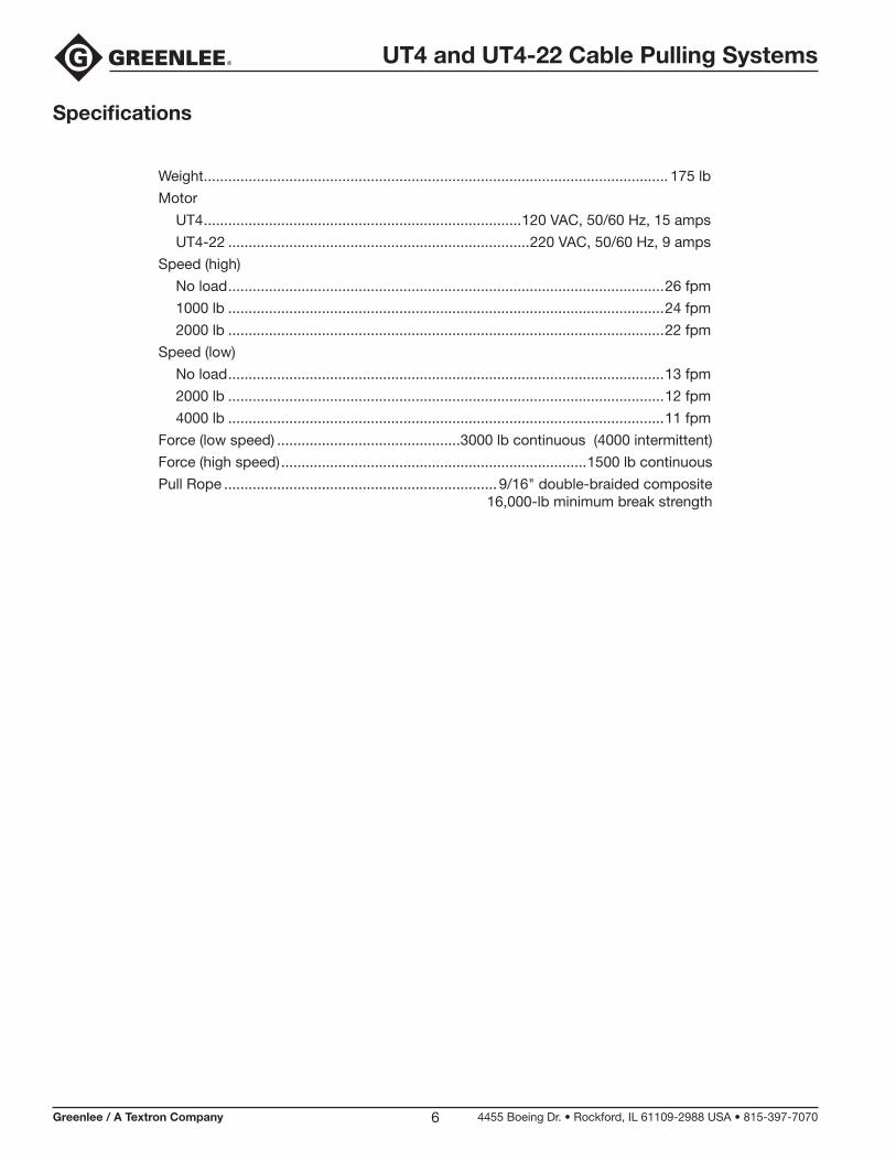
Weight .................................................................................................................. 175 lb
Motor
UT4 ..............................................................................120 VAC, 50/60 Hz, 15 amps
UT4-22 ..........................................................................220 VAC, 50/60 Hz, 9 amps
Speed (high)
No load ...........................................................................................................26 fpm
1000 lb ...........................................................................................................24 fpm
2000 lb ...........................................................................................................22 fpm
Speed (low)
No load ...........................................................................................................13 fpm
2000 lb ...........................................................................................................12 fpm
4000 lb ...........................................................................................................11 fpm
Force (low speed) .............................................3000 lb continuous (4000 intermittent)
Force (high speed) ...........................................................................1500 lb continuous
Pull Rope ...................................................................9/16" double-braided composite16,000-lb minimum break strength
UT4 and UT4-22 Cable Pulling Systems
Greenlee / A Textron Company 4455 Boeing Dr. • Rockford, IL 61109-2988 USA • 815-397-70707
Initial Assembly
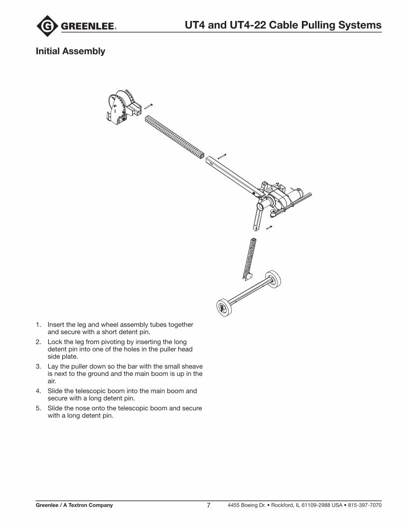
1. Insert the leg and wheel assembly tubes together and secure with a short detent pin.
2. Lock the leg from pivoting by inserting the long detent pin into one of the holes in the puller head side plate.
3. Lay the puller down so the bar with the small sheave is next to the ground and the main boom is up in the air.
4. Slide the telescopic boom into the main boom and secure with a long detent pin.
5. Slide the nose onto the telescopic boom and secure with a long detent pin.
UT4 and UT4-22 Cable Pulling Systems
Greenlee / A Textron Company 4455 Boeing Dr. • Rockford, IL 61109-2988 USA • 815-397-70708
Assembly
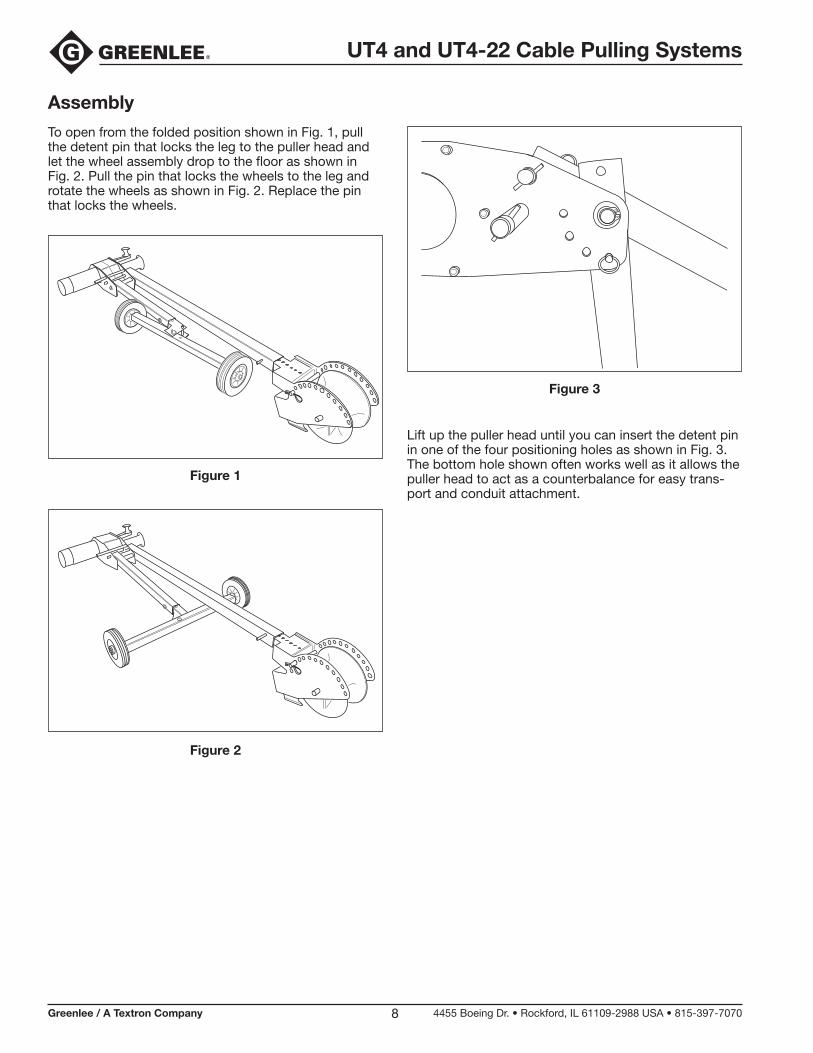
To open from the folded position shown in Fig. 1, pull the detent pin that locks the leg to the puller head and let the wheel assembly drop to the floor as shown in Fig. 2. Pull the pin that locks the wheels to the leg and rotate the wheels as shown in Fig. 2. Replace the pin that locks the wheels.
Lift up the puller head until you can insert the detent pin in one of the four positioning holes as shown in Fig. 3. The bottom hole shown often works well as it allows the puller head to act as a counterbalance for easy trans-port and conduit attachment.
Figure 1
Figure 2
Figure 3
UT4 and UT4-22 Cable Pulling Systems
Greenlee / A Textron Company 4455 Boeing Dr. • Rockford, IL 61109-2988 USA • 815-397-70709
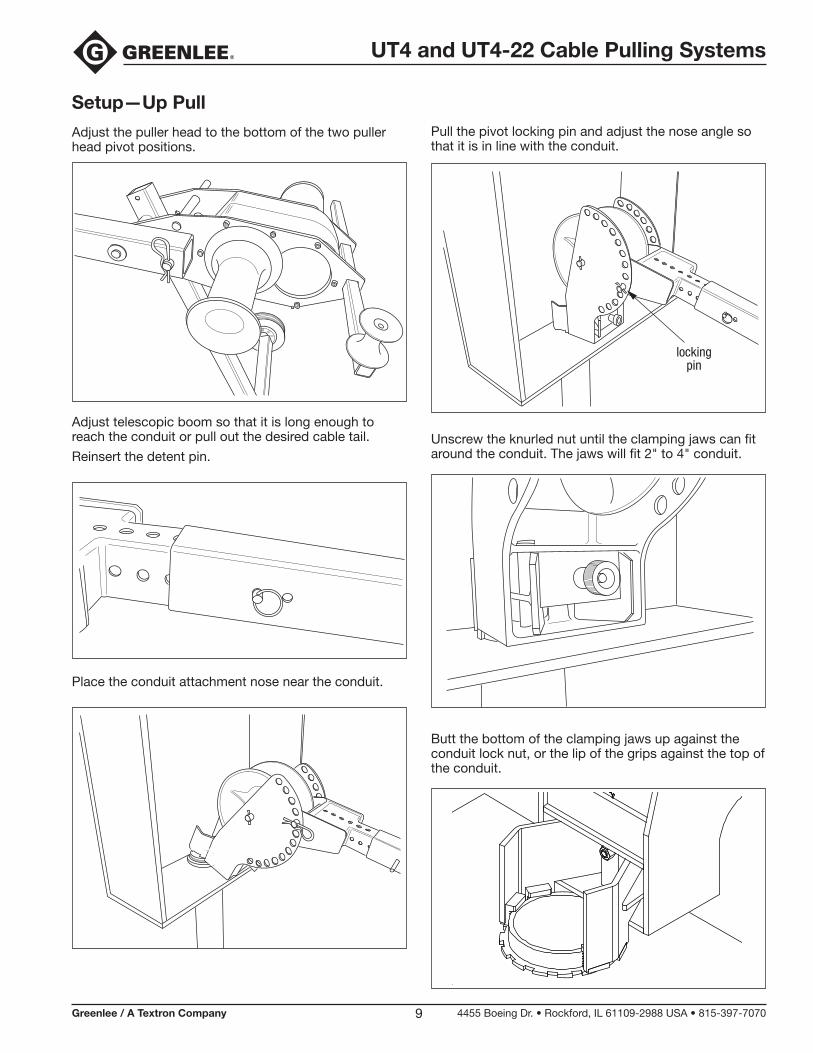
Setup—Up Pull
Adjust the puller head to the bottom of the two puller head pivot positions.
Adjust telescopic boom so that it is long enough to reach the conduit or pull out the desired cable tail.
Reinsert the detent pin.
Place the conduit attachment nose near the conduit.
Pull the pivot locking pin and adjust the nose angle so that it is in line with the conduit.
Unscrew the knurled nut until the clamping jaws can fit around the conduit. The jaws will fit 2" to 4" conduit.
Butt the bottom of the clamping jaws up against the conduit lock nut, or the lip of the grips against the top of the conduit.
lockingpin
UT4 and UT4-22 Cable Pulling Systems
Greenlee / A Textron Company 4455 Boeing Dr. • Rockford, IL 61109-2988 USA • 815-397-707010
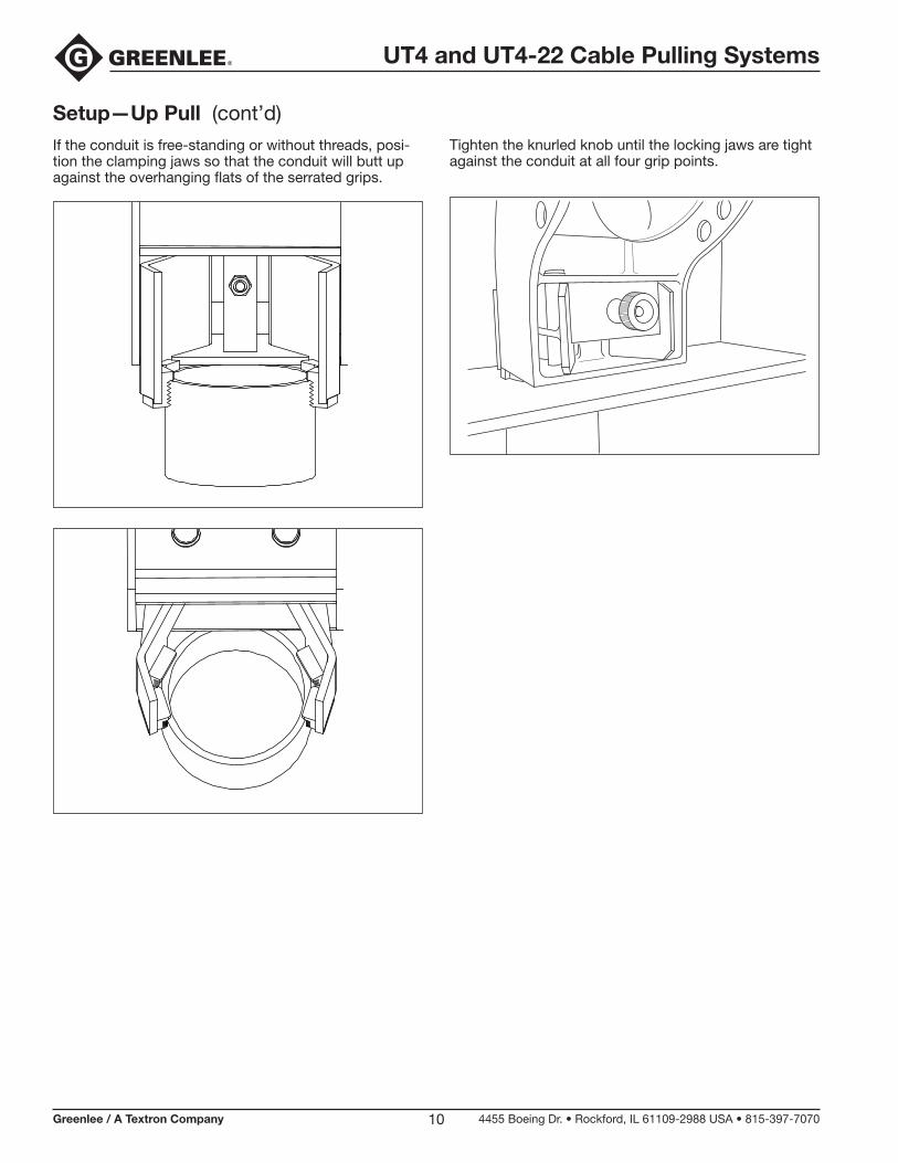
If the conduit is free-standing or without threads, posi-tion the clamping jaws so that the conduit will butt up against the overhanging flats of the serrated grips.
Setup—Up Pull (cont’d)Tighten the knurled knob until the locking jaws are tight against the conduit at all four grip points.
UT4 and UT4-22 Cable Pulling Systems
Greenlee / A Textron Company 4455 Boeing Dr. • Rockford, IL 61109-2988 USA • 815-397-707011
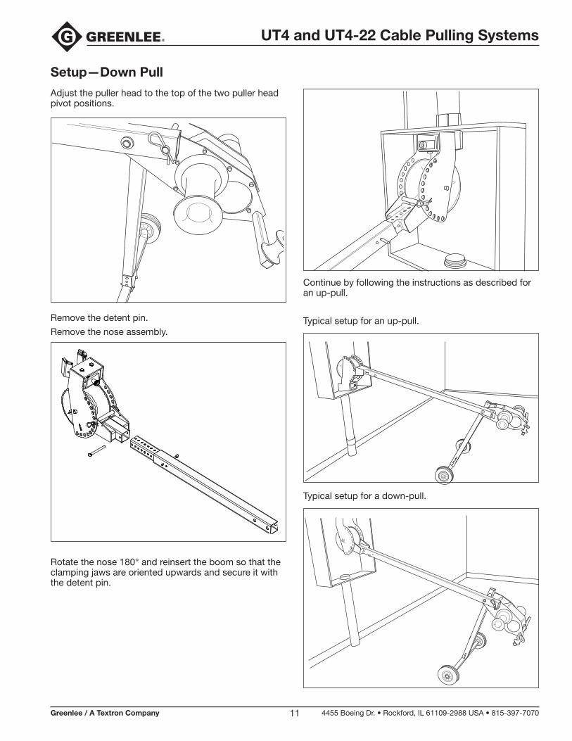
Setup—Down Pull
Adjust the puller head to the top of the two puller head pivot positions.
Remove the detent pin.
Remove the nose assembly.
Rotate the nose 180° and reinsert the boom so that the clamping jaws are oriented upwards and secure it with the detent pin.
Continue by following the instructions as described for an up-pull.
Typical setup for an up-pull.
Typical setup for a down-pull.
UT4 and UT4-22 Cable Pulling Systems
Greenlee / A Textron Company 4455 Boeing Dr. • Rockford, IL 61109-2988 USA • 815-397-707012
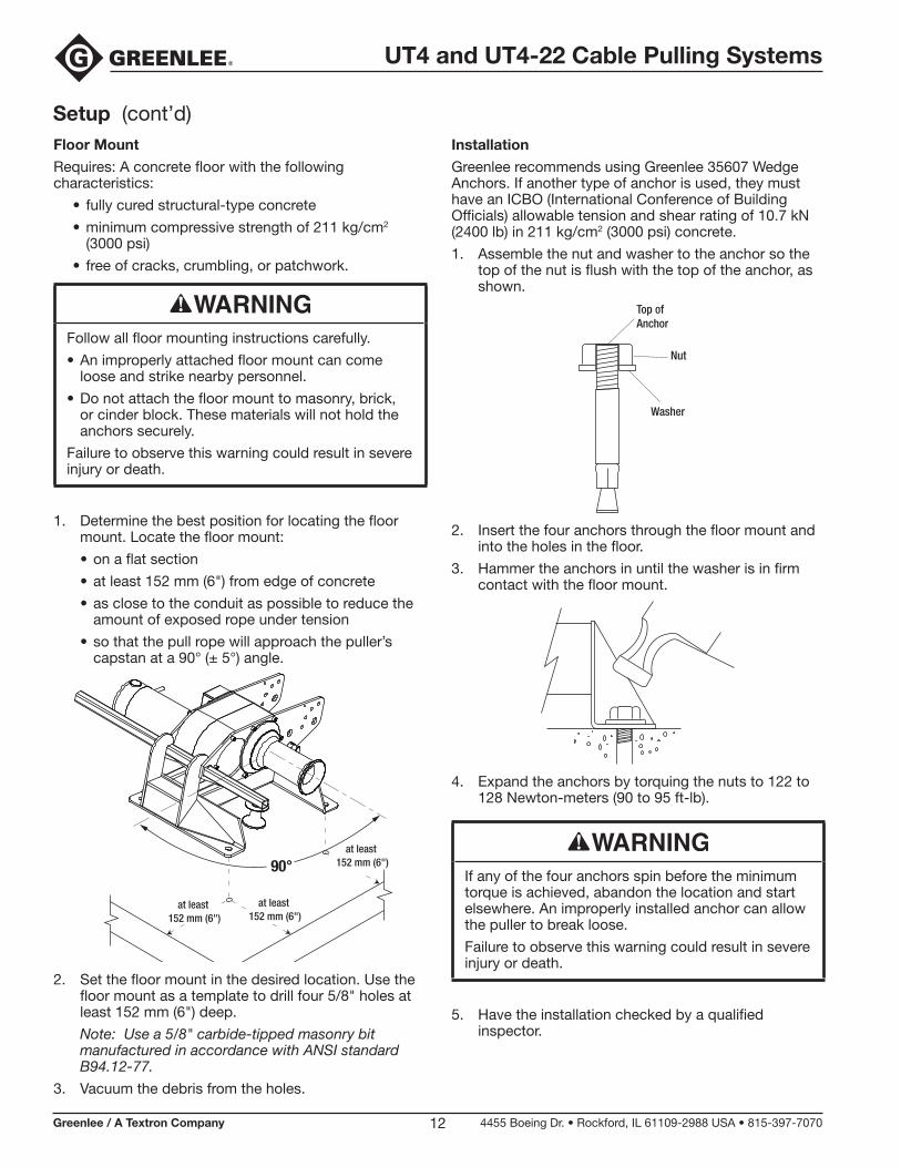
Setup (cont’d)Floor Mount
Requires: A concrete floor with the following characteristics:
• fully cured structural-type concrete
• minimum compressive strength of 211 kg/cm2 (3000 psi)
• free of cracks, crumbling, or patchwork.
Follow all floor mounting instructions carefully.
• An improperly attached floor mount can come loose and strike nearby personnel.
• Do not attach the floor mount to masonry, brick, or cinder block. These materials will not hold the anchors securely.
Failure to observe this warning could result in severe injury or death.
1. Determine the best position for locating the floor mount. Locate the floor mount:
• on a flat section
• at least 152 mm (6") from edge of concrete
• as close to the conduit as possible to reduce the amount of exposed rope under tension
• so that the pull rope will approach the puller’s capstan at a 90° (± 5°) angle.
90°
at least 152 mm (6")
at least 152 mm (6")
at least 152 mm (6")
2. Set the floor mount in the desired location. Use the floor mount as a template to drill four 5/8" holes at least 152 mm (6") deep.
Note: Use a 5/8" carbide-tipped masonry bit manufactured in accordance with ANSI standard B94.12-77.
3. Vacuum the debris from the holes.
Installation
Greenlee recommends using Greenlee 35607 Wedge Anchors. If another type of anchor is used, they must have an ICBO (International Conference of Building Officials) allowable tension and shear rating of 10.7 kN (2400 lb) in 211 kg/cm2 (3000 psi) concrete.
1. Assemble the nut and washer to the anchor so the top of the nut is flush with the top of the anchor, as shown.
Top ofAnchor
Nut
Washer
2. Insert the four anchors through the floor mount and into the holes in the floor.
3. Hammer the anchors in until the washer is in firm contact with the floor mount.
4. Expand the anchors by torquing the nuts to 122 to 128 Newton-meters (90 to 95 ft-lb).
If any of the four anchors spin before the minimum torque is achieved, abandon the location and start elsewhere. An improperly installed anchor can allow the puller to break loose.
Failure to observe this warning could result in severe injury or death.
5. Have the installation checked by a qualified inspector.
UT4 and UT4-22 Cable Pulling Systems
Greenlee / A Textron Company 4455 Boeing Dr. • Rockford, IL 61109-2988 USA • 815-397-707013
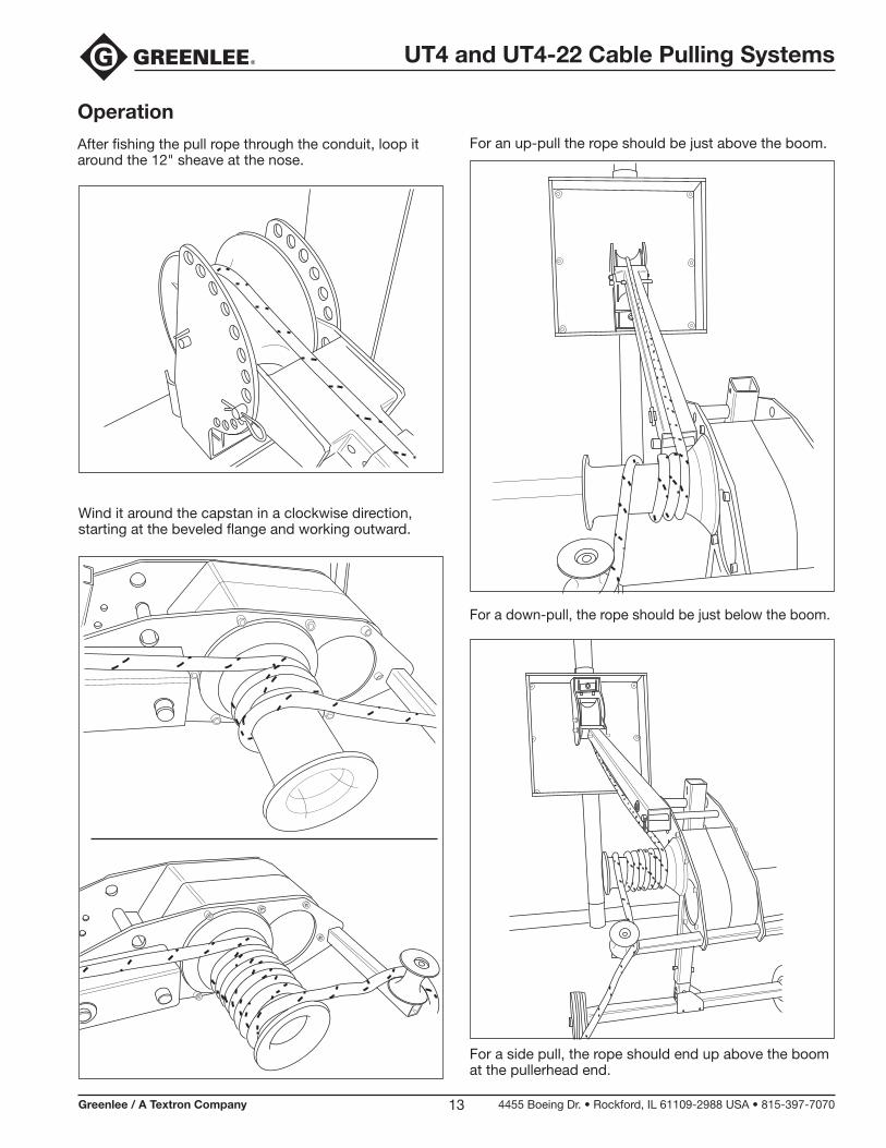
Operation
After fishing the pull rope through the conduit, loop it around the 12" sheave at the nose.
For an up-pull the rope should be just above the boom.
Wind it around the capstan in a clockwise direction, starting at the beveled flange and working outward.
For a down-pull, the rope should be just below the boom.
For a side pull, the rope should end up above the boom at the pullerhead end.
UT4 and UT4-22 Cable Pulling Systems
Greenlee / A Textron Company 4455 Boeing Dr. • Rockford, IL 61109-2988 USA • 815-397-707014
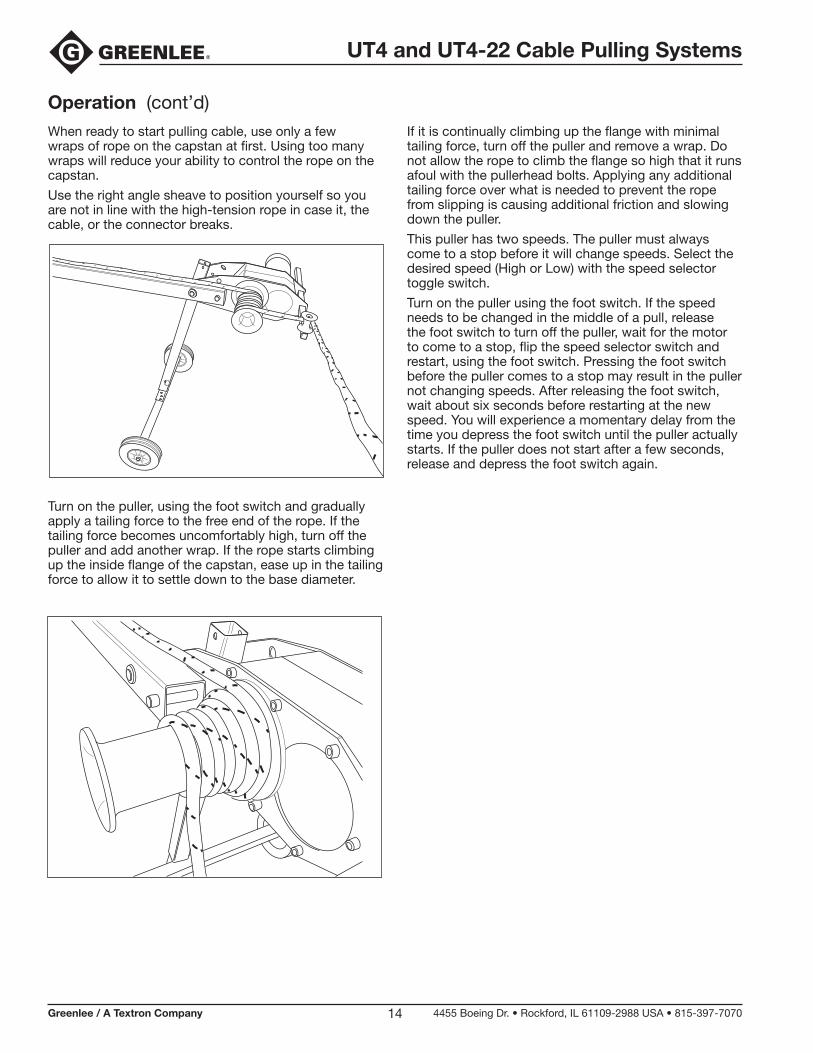
When ready to start pulling cable, use only a few wraps of rope on the capstan at first. Using too many wraps will reduce your ability to control the rope on the capstan.
Use the right angle sheave to position yourself so you are not in line with the high-tension rope in case it, the cable, or the connector breaks.
Operation (cont’d)
Turn on the puller, using the foot switch and gradually apply a tailing force to the free end of the rope. If the tailing force becomes uncomfortably high, turn off the puller and add another wrap. If the rope starts climbing up the inside flange of the capstan, ease up in the tailing force to allow it to settle down to the base diameter.
If it is continually climbing up the flange with minimal tailing force, turn off the puller and remove a wrap. Do not allow the rope to climb the flange so high that it runs afoul with the pullerhead bolts. Applying any additional tailing force over what is needed to prevent the rope from slipping is causing additional friction and slowing down the puller.
This puller has two speeds. The puller must always come to a stop before it will change speeds. Select the desired speed (High or Low) with the speed selector toggle switch.
Turn on the puller using the foot switch. If the speed needs to be changed in the middle of a pull, release the foot switch to turn off the puller, wait for the motor to come to a stop, flip the speed selector switch and restart, using the foot switch. Pressing the foot switch before the puller comes to a stop may result in the puller not changing speeds. After releasing the foot switch, wait about six seconds before restarting at the new speed. You will experience a momentary delay from the time you depress the foot switch until the puller actually starts. If the puller does not start after a few seconds, release and depress the foot switch again.
UT4 and UT4-22 Cable Pulling Systems
Greenlee / A Textron Company 4455 Boeing Dr. • Rockford, IL 61109-2988 USA • 815-397-707015
Maintenance
Shut off motor and unplug unit before dismantling or servicing.
Failure to observe this warning will result in severe injury or death.
Capstan
Wear
Check for wear on the outside of the capstan. If the rope has worn a groove deeper than 0.10" on the 3" diameter portion of the capstan, replace it.
Adjustment
If the capstan or puller frame is replaced, adjust the axial free play to less than 1/32". Assemble the inner thrust washers and capstan to the frame without the chain. Attach with the bolt and retaining flat washer. If the capstan binds, add 52023123 shim washers one at a time until it rotates freely. If it has more than 1/32" of axial free play, add 50179160 fiber washers to set the free play at less than 1/32".
Motor
Commutator Brushes
Check the commutator brushes after every 40 hours of operation. Remove the motor brush caps and brushes. Measure the brush lengths. If length of either brush is less than 3/8", replace both brushes.
UT4 and UT4-22 Cable Pulling Systems
Greenlee / A Textron Company 4455 Boeing Dr. • Rockford, IL 61109-2988 USA • 815-397-707016
Illustration
1
2
3
4
5
5
5
6
6
2
1
3
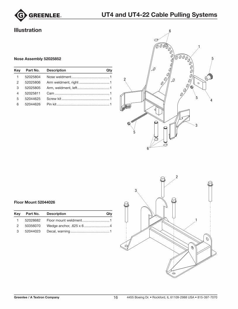
Nose Assembly 52025852
Key Part No. Description Qty
1 52025804 Nose weldment .......................................1
2 52025806 Arm weldment, right ...............................1
3 52025805 Arm, weldment, left .................................1
4 52025811 Cam ........................................................1
5 52044625 Screw kit .................................................1
6 52044626 Pin kit ......................................................1
Floor Mount 52044026
Key Part No. Description Qty
1 52028682 Floor mount weldment ............................1
2 50356070 Wedge anchor, .625 x 6 ..........................4
3 52044023 Decal, warning ........................................1
UT4 and UT4-22 Cable Pulling Systems
Greenlee / A Textron Company 4455 Boeing Dr. • Rockford, IL 61109-2988 USA • 815-397-707017
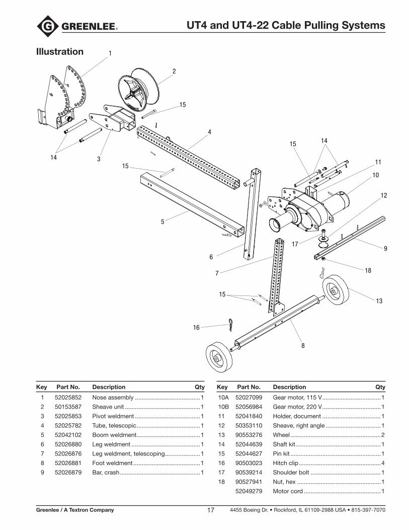
Illustration
1 52025852 Nose assembly .......................................1
2 50153587 Sheave unit .............................................1
3 52025853 Pivot weldment .......................................1
4 52025782 Tube, telescopic ......................................1
5 52042102 Boom weldment ......................................1
6 52026880 Leg weldment .........................................1
7 52026876 Leg weldment, telescoping .....................1
8 52026881 Foot weldment ........................................1
9 52026879 Bar, crash ................................................1
1
2
3
4
5
6
7
8
9
10
11
12
13
14
1415
15
15
15
16
17
18
10A 52027099 Gear motor, 115 V ...................................1
10B 52056984 Gear motor, 220 V ...................................1
11 52041840 Holder, document ...................................1
12 50353110 Sheave, right angle .................................1
13 90553276 Wheel ......................................................2
14 52044639 Shaft kit ...................................................1
15 52044627 Pin kit ......................................................1
16 90503023 Hitch clip .................................................4
17 90539214 Shoulder bolt ..........................................1
18 90527941 Nut, hex ..................................................1
52049279 Motor cord ..............................................1
Key Part No. Description Qty Key Part No. Description Qty
UT4 and UT4-22 Cable Pulling Systems
Greenlee / A Textron Company 4455 Boeing Dr. • Rockford, IL 61109-2988 USA • 815-397-707018
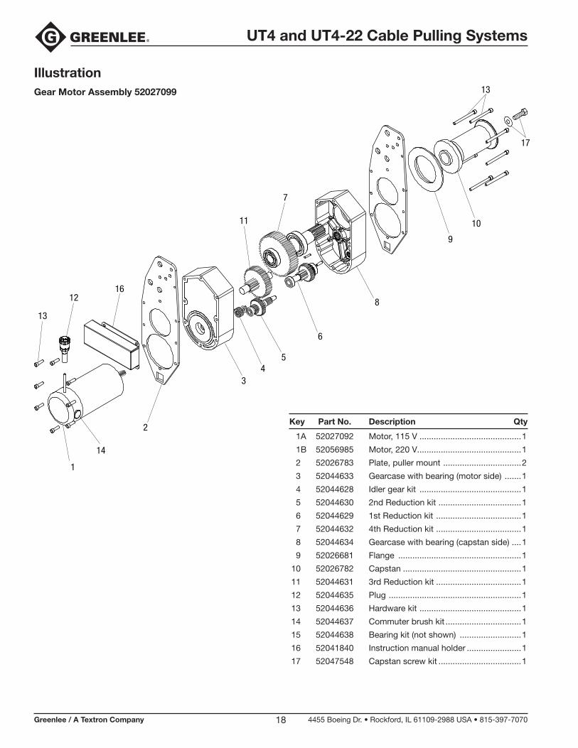
IllustrationGear Motor Assembly 52027099
1A 52027092 Motor, 115 V ...........................................1
1B 52056985 Motor, 220 V............................................1
2 52026783 Plate, puller mount .................................2
3 52044633 Gearcase with bearing (motor side) .......1
4 52044628 Idler gear kit ...........................................1
5 52044630 2nd Reduction kit ...................................1
6 52044629 1st Reduction kit ....................................1
7 52044632 4th Reduction kit ....................................1
8 52044634 Gearcase with bearing (capstan side) ....1
9 52026681 Flange ....................................................1
10 52026782 Capstan ..................................................1
11 52044631 3rd Reduction kit ....................................1
12 52044635 Plug ........................................................1
13 52044636 Hardware kit ...........................................1
14 52044637 Commuter brush kit ................................1
15 52044638 Bearing kit (not shown) ..........................1
16 52041840 Instruction manual holder .......................1
17 52047548 Capstan screw kit ...................................1
1
2
34
5
6
7
8
9
1011
12
13
13
14
16
17
Key Part No. Description Qty
UT4 and UT4-22 Cable Pulling Systems
Greenlee / A Textron Company 4455 Boeing Dr. • Rockford, IL 61109-2988 USA • 815-397-707019
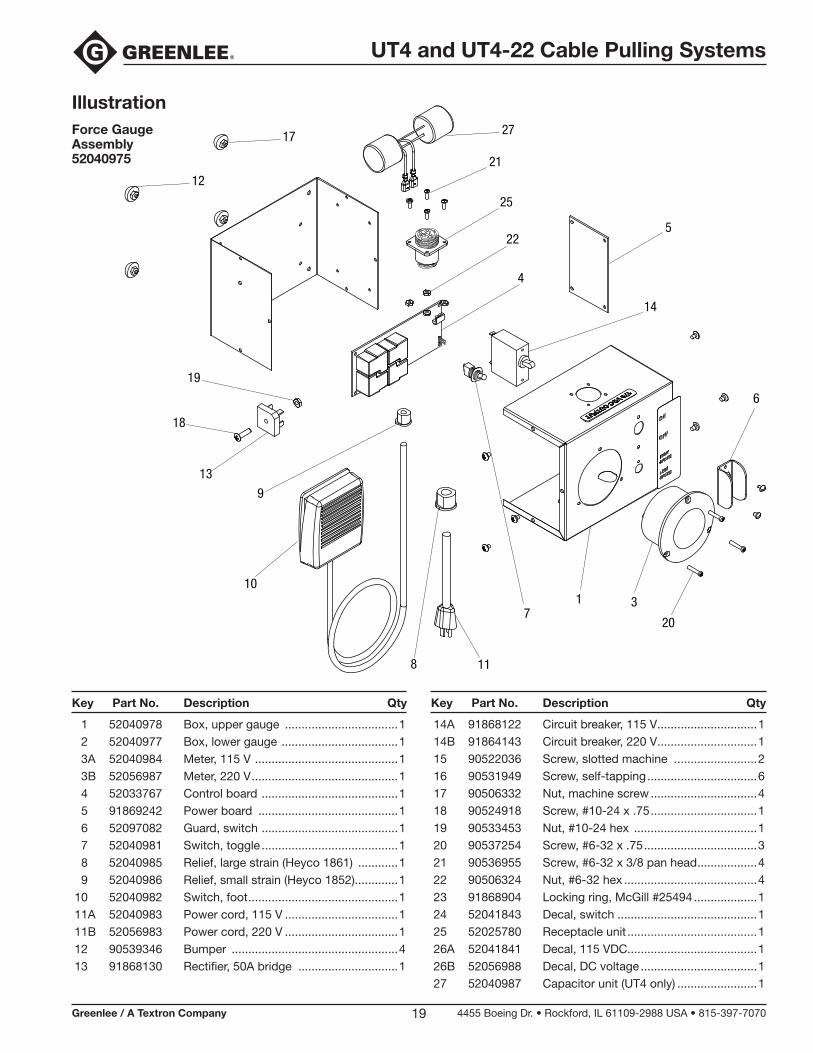
1 52040978 Box, upper gauge ..................................1 2 52040977 Box, lower gauge ...................................1 3A 52040984 Meter, 115 V ...........................................1 3B 52056987 Meter, 220 V ............................................1 4 52033767 Control board .........................................1 5 91869242 Power board ..........................................1 6 52097082 Guard, switch .........................................1 7 52040981 Switch, toggle .........................................1 8 52040985 Relief, large strain (Heyco 1861) ............1 9 52040986 Relief, small strain (Heyco 1852).............1 10 52040982 Switch, foot .............................................1 11A 52040983 Power cord, 115 V ..................................1 11B 52056983 Power cord, 220 V ..................................1 12 90539346 Bumper ..................................................4 13 91868130 Rectifier, 50A bridge ..............................1
14A 91868122 Circuit breaker, 115 V ..............................1 14B 91864143 Circuit breaker, 220 V ..............................1 15 90522036 Screw, slotted machine .........................2 16 90531949 Screw, self-tapping .................................6 17 90506332 Nut, machine screw ................................4 18 90524918 Screw, #10-24 x .75 ................................1 19 90533453 Nut, #10-24 hex .....................................1 20 90537254 Screw, #6-32 x .75 ..................................3 21 90536955 Screw, #6-32 x 3/8 pan head ..................4 22 90506324 Nut, #6-32 hex ........................................4 23 91868904 Locking ring, McGill #25494 ...................1 24 52041843 Decal, switch ..........................................1 25 52025780 Receptacle unit .......................................1 26A 52041841 Decal, 115 VDC.......................................1 26B 52056988 Decal, DC voltage ...................................1 27 52040987 Capacitor unit (UT4 only) ........................1
IllustrationForce Gauge Assembly 52040975
Key Part No. Description Qty Key Part No. Description Qty
27
21
25
22
4
5
14
6
20
317
118
10
9
18
19
13
17
12
USA 800-435-0786 Fax: 800-451-2632 815-397-7070 Fax: 815-397-1865Canada 800-435-0786 Fax: 800-524-2853International +1-815-397-7070 Fax: +1-815-397-9247
4455 Boeing Drive • Rockford, IL 61109-2988 • USA • 815-397-7070An ISO 9001 Company • Greenlee Textron Inc. is a subsidiary of Textron Inc.
www.greenlee.com Printed in USA