USPAS Course on Photocathode Physicsuspas.fnal.gov/materials/12UTA/Cathode_8.pdf · Superlattice +...
75
USPAS Course on Photocathode Physics John Smedley, BNL and Matt Poelker, TJNAF Austin, TX January 16-20, 2011 Lecture 8 Practical Matters
Transcript of USPAS Course on Photocathode Physicsuspas.fnal.gov/materials/12UTA/Cathode_8.pdf · Superlattice +...
USPAS Course on Photocathode Physics
John Smedley, BNL and Matt Poelker, TJNAF
Austin, TX January 16-20, 2011
Lecture 8 Practical Matters
Lecture 8: • Ion Bombardment • High Voltage: avoiding breakdown and
field emission • A clean photocathode • Vacuum Hot Filament Gauges
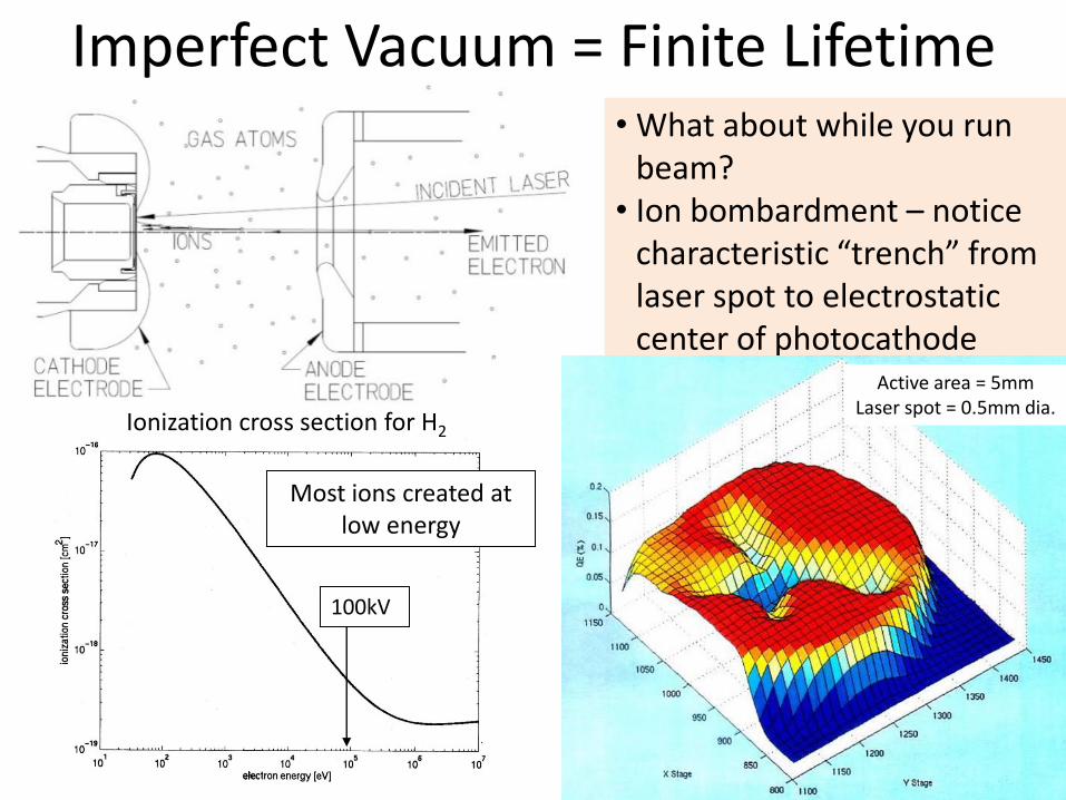
Imperfect Vacuum = Finite Lifetime
Ionization cross section for H2
Most ions created at low energy
100kV
• What about while you run beam?
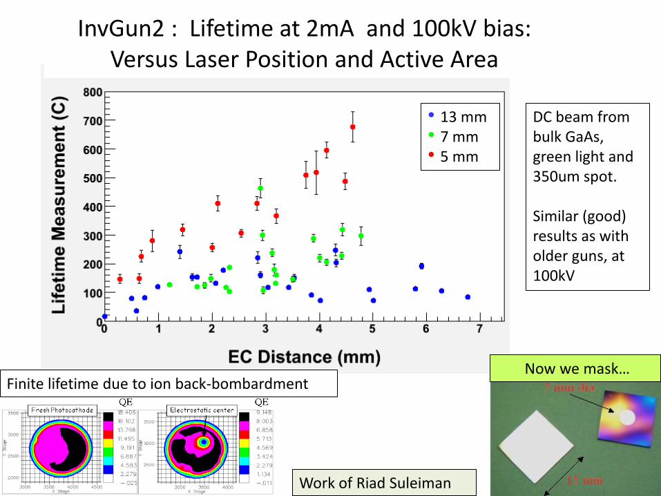
• Ion bombardment – notice characteristic “trench” from laser spot to electrostatic center of photocathode
Active area = 5mm Laser spot = 0.5mm dia.
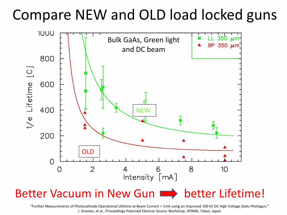
Compare NEW and OLD load locked guns
OLD
NEW
Bulk GaAs, Green light and DC beam
“Further Measurements of Photocathode Operational Lifetime at Beam Current > 1mA using an Improved 100 kV DC High Voltage GaAs Photogun,” J. Grames, et al., Proceedings Polarized Electron Source Workshop, SPIN06, Tokyo, Japan
Better Vacuum in New Gun better Lifetime!
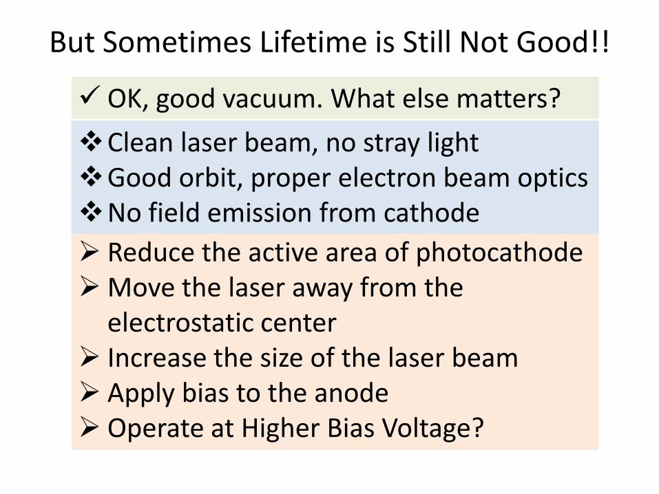
But Sometimes Lifetime is Still Not Good!!
OK, good vacuum. What else matters?
Reduce the active area of photocathode Move the laser away from the
electrostatic center Increase the size of the laser beam Apply bias to the anode Operate at Higher Bias Voltage?
Clean laser beam, no stray light Good orbit, proper electron beam optics No field emission from cathode
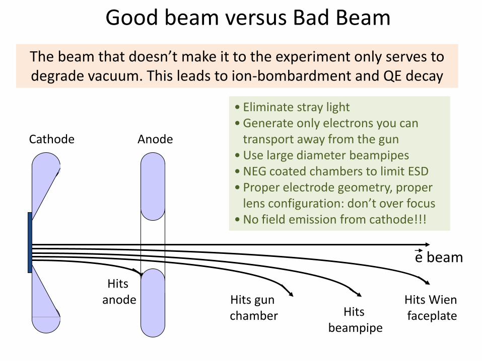
Good beam versus Bad Beam
• Eliminate stray light • Generate only electrons you can
transport away from the gun • Use large diameter beampipes • NEG coated chambers to limit ESD • Proper electrode geometry, proper
lens configuration: don’t over focus • No field emission from cathode!!!
Cathode Anode
Hits beampipe
Hits gun chamber
Hits Wien faceplate
e beam
Hits anode
The beam that doesn’t make it to the experiment only serves to degrade vacuum. This leads to ion-bombardment and QE decay
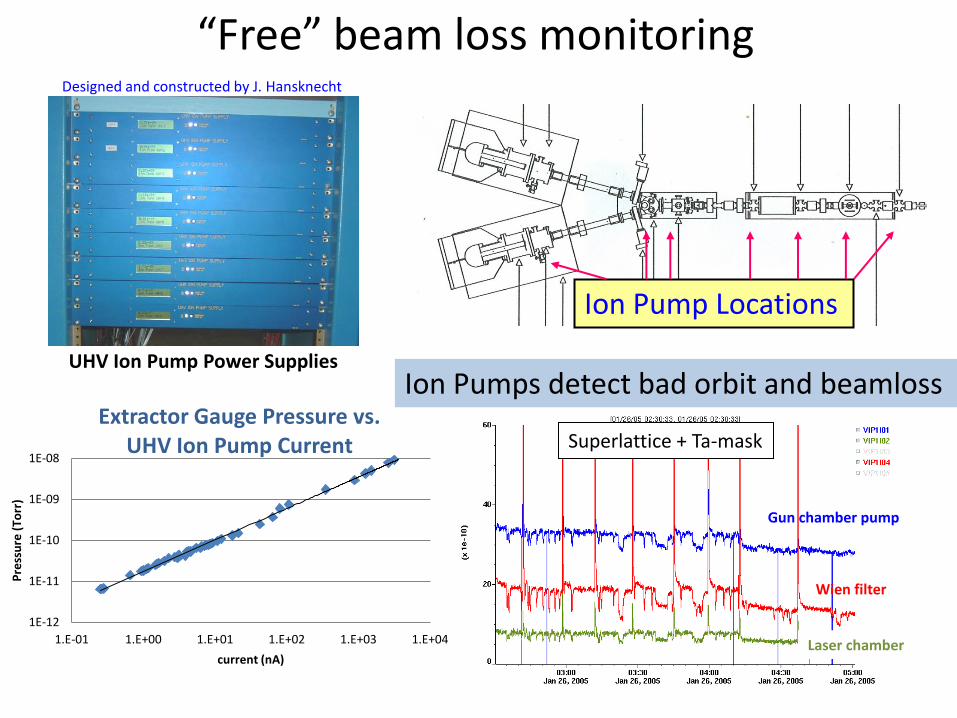
Ion Pump Locations
Designed and constructed by J. Hansknecht
UHV Ion Pump Power Supplies
“Free” beam loss monitoring
Ion Pumps detect bad orbit and beamloss
Gun chamber pump
Wien filter
Laser chamber
Superlattice + Ta-mask
1E-12
1E-11
1E-10
1E-09
1E-08
1.E-01 1.E+00 1.E+01 1.E+02 1.E+03 1.E+04
Pre
ssu
re (
Torr
)
current (nA)
Extractor Gauge Pressure vs. UHV Ion Pump Current
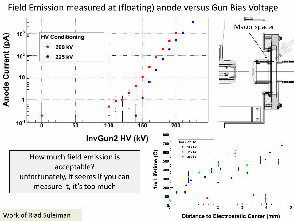
Work of Riad Suleiman
How much field emission is acceptable?
unfortunately, it seems if you can measure it, it’s too much
Field Emission measured at (floating) anode versus Gun Bias Voltage
Macor spacer
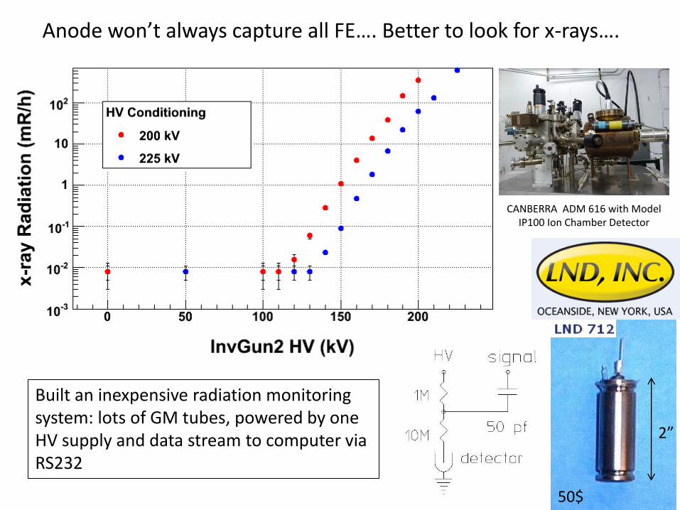
Anode won’t always capture all FE…. Better to look for x-rays….
2”
50$
Built an inexpensive radiation monitoring system: lots of GM tubes, powered by one HV supply and data stream to computer via RS232
CANBERRA ADM 616 with Model IP100 Ion Chamber Detector
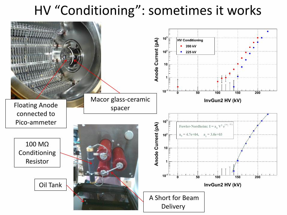
HV “Conditioning”: sometimes it works
Floating Anode connected to Pico-ammeter
Macor glass-ceramic spacer
100 MΩ Conditioning
Resistor
Oil Tank
A Short for Beam Delivery
Lifetime Experiments at the Injector Test Cave
SUITCASE
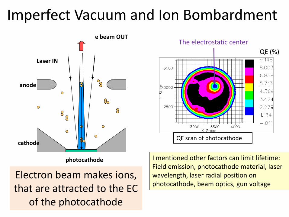
Imperfect Vacuum and Ion Bombardment
QE scan of photocathode
QE (%)
photocathode
anode
cathode
Laser IN
e beam OUT
I mentioned other factors can limit lifetime: Field emission, photocathode material, laser wavelength, laser radial position on photocathode, beam optics, gun voltage
The electrostatic center
Electron beam makes ions, that are attracted to the EC
of the photocathode
electron beam OUT
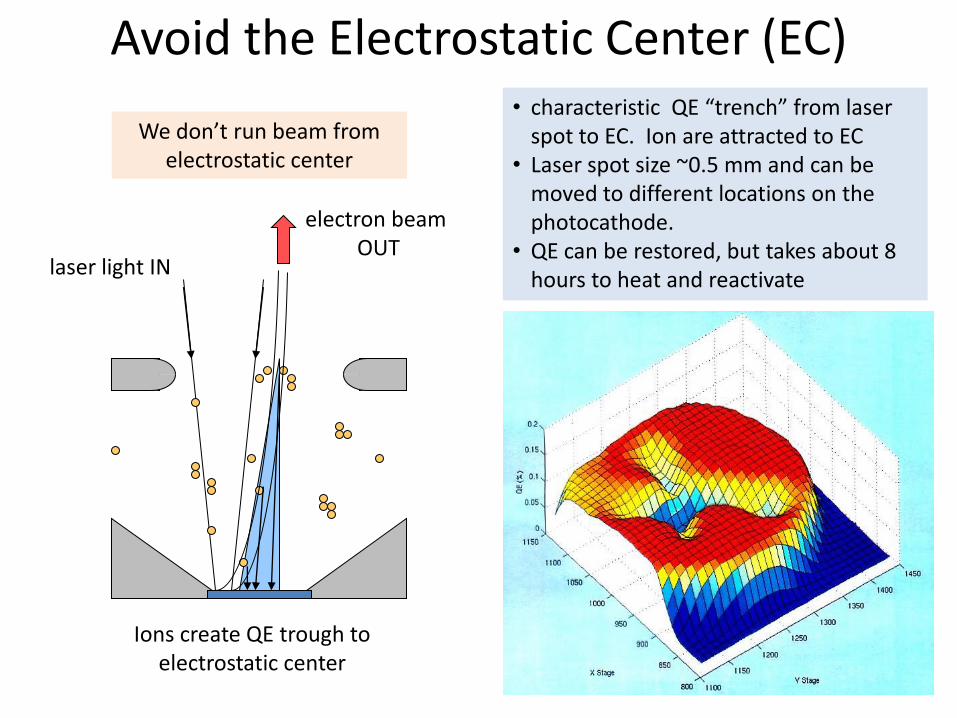
We don’t run beam from electrostatic center
laser light IN
Ions create QE trough to electrostatic center
Avoid the Electrostatic Center (EC) • characteristic QE “trench” from laser
spot to EC. Ion are attracted to EC • Laser spot size ~0.5 mm and can be
moved to different locations on the photocathode.
• QE can be restored, but takes about 8 hours to heat and reactivate
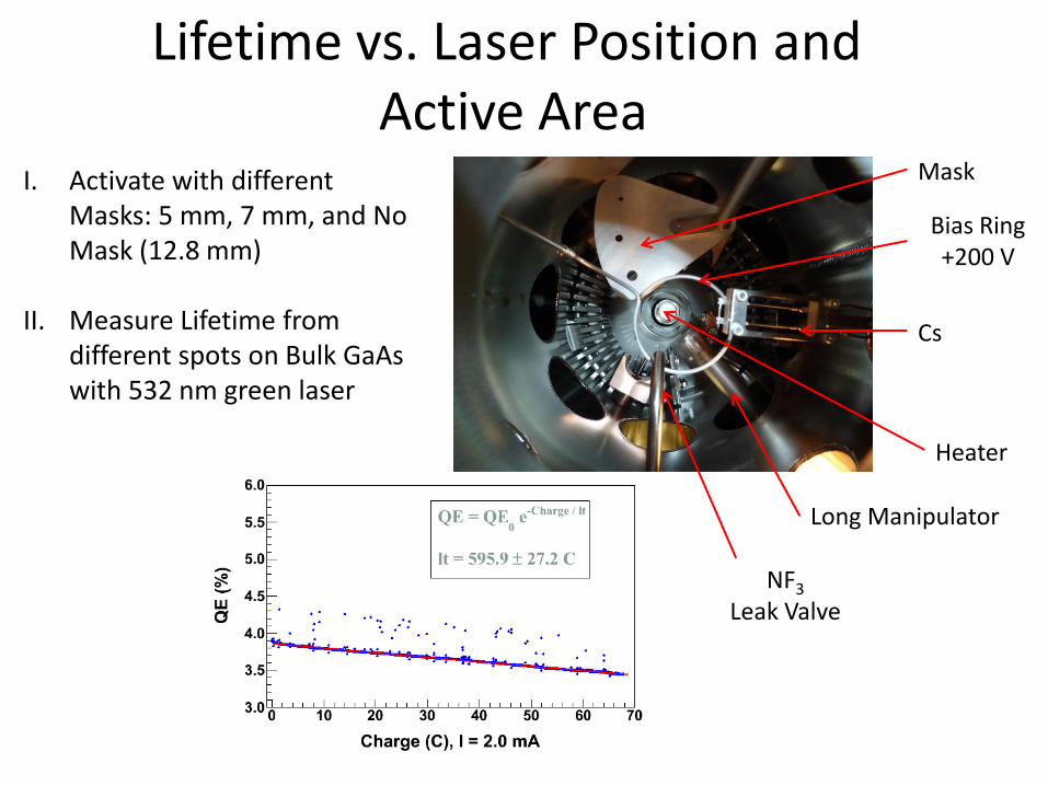
Lifetime vs. Laser Position and Active Area
I. Activate with different Masks: 5 mm, 7 mm, and No Mask (12.8 mm)
II. Measure Lifetime from different spots on Bulk GaAs with 532 nm green laser
NF3 Leak Valve
Cs
Bias Ring +200 V
Mask
Heater
Long Manipulator
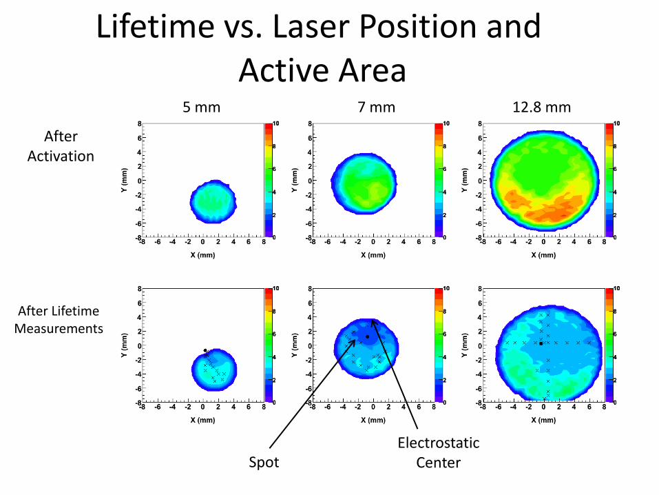
After Activation
After Lifetime Measurements
Electrostatic Center Spot
5 mm 7 mm 12.8 mm
Lifetime vs. Laser Position and Active Area
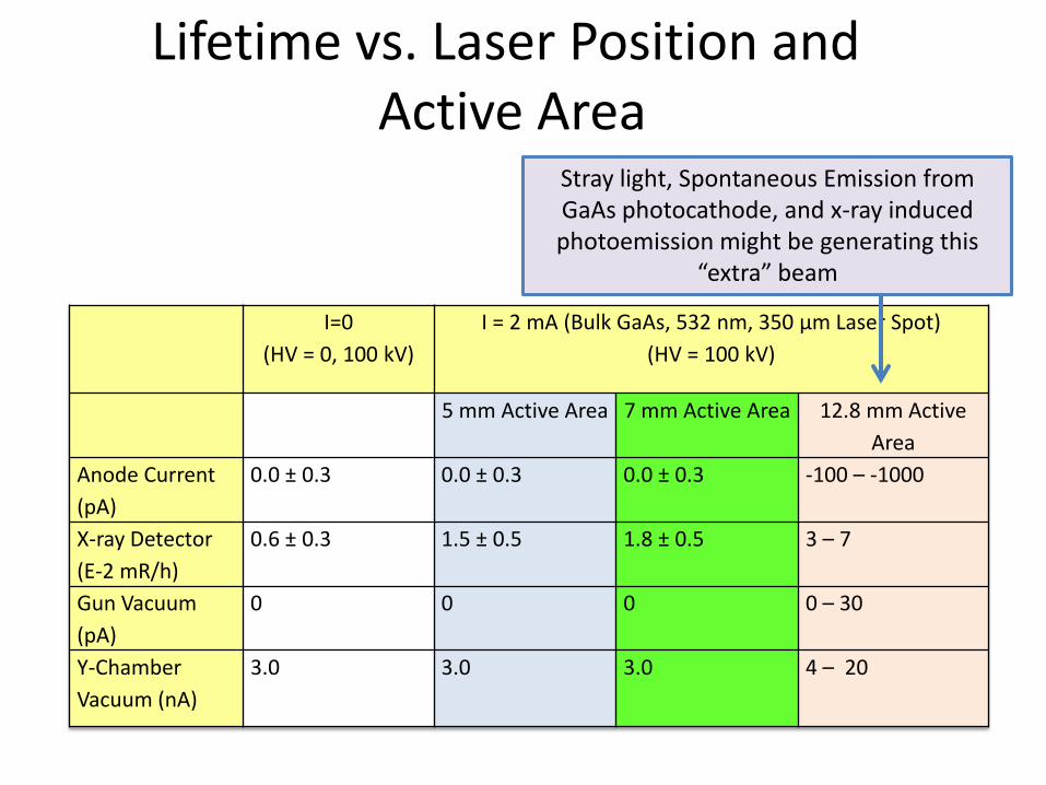
I=0
(HV = 0, 100 kV)
I = 2 mA (Bulk GaAs, 532 nm, 350 μm Laser Spot)
(HV = 100 kV)
5 mm Active Area 7 mm Active Area 12.8 mm Active
Area
Anode Current
(pA)
0.0 ± 0.3 0.0 ± 0.3 0.0 ± 0.3 -100 – -1000
X-ray Detector
(E-2 mR/h)
0.6 ± 0.3 1.5 ± 0.5 1.8 ± 0.5 3 – 7
Gun Vacuum
(pA)
0 0 0 0 – 30
Y-Chamber
Vacuum (nA)
3.0 3.0 3.0 4 – 20
Lifetime vs. Laser Position and Active Area
Stray light, Spontaneous Emission from GaAs photocathode, and x-ray induced photoemission might be generating this
“extra” beam
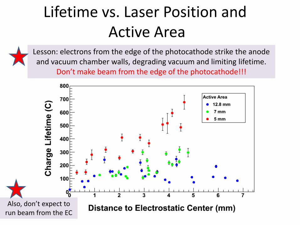
Lesson: electrons from the edge of the photocathode strike the anode and vacuum chamber walls, degrading vacuum and limiting lifetime.
Don’t make beam from the edge of the photocathode!!!
Lifetime vs. Laser Position and Active Area
Also, don’t expect to run beam from the EC
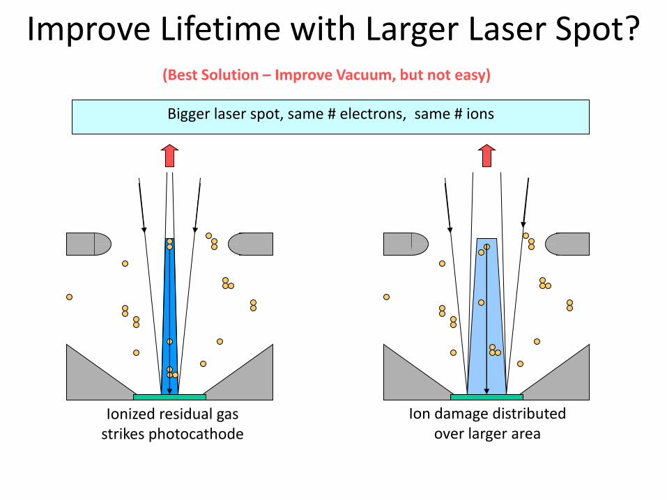
Improve Lifetime with Larger Laser Spot? (Best Solution – Improve Vacuum, but not easy)
Bigger laser spot, same # electrons, same # ions
Ionized residual gas strikes photocathode
Ion damage distributed over larger area
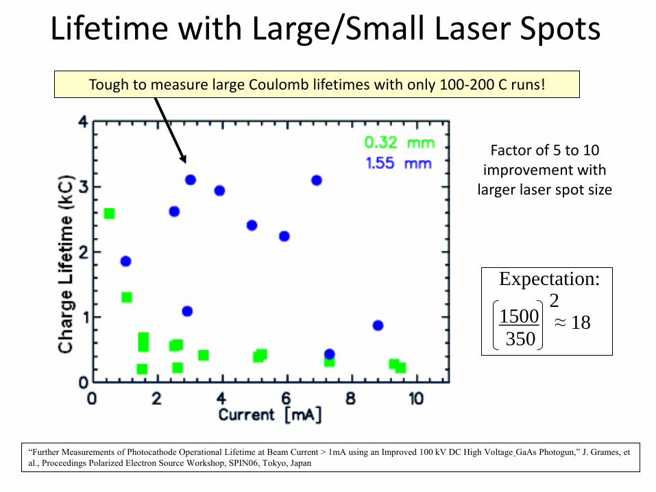
Lifetime with Large/Small Laser Spots
1500 350
2 ≈ 18
Expectation:
“Further Measurements of Photocathode Operational Lifetime at Beam Current > 1mA using an Improved 100 kV DC High Voltage GaAs Photogun,” J. Grames, et
al., Proceedings Polarized Electron Source Workshop, SPIN06, Tokyo, Japan
Tough to measure large Coulomb lifetimes with only 100-200 C runs!
Factor of 5 to 10 improvement with
larger laser spot size
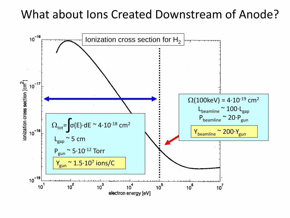
Ionization cross section for H2
Wtot= σ(E)∙dE ~ 4∙10-18 cm2 ∫ Lgap ~ 5 cm
Pgun ~ 5∙10-12 Torr
Ygun ~ 1.5∙107 ions/C
W(100keV) = 4∙10-19 cm2
Lbeamline ~ 100∙Lgap
Pbeamline ~ 20∙Pgun
Ybeamline ~ 200∙Ygun
What about Ions Created Downstream of Anode?
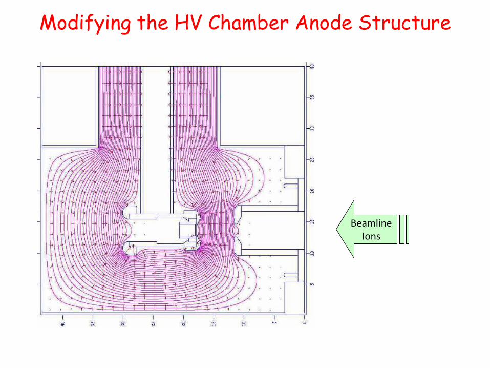
Modifying the HV Chamber Anode Structure
Beamline Ions
Beamline Ions
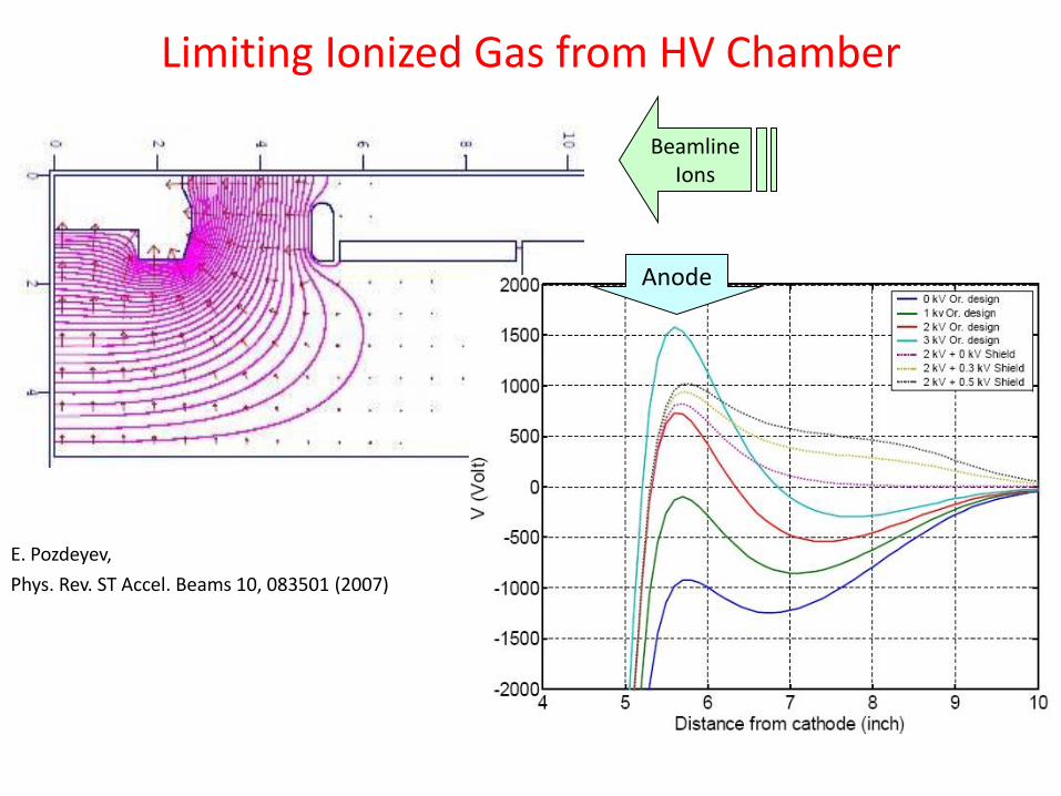
Anode
Limiting Ionized Gas from HV Chamber
E. Pozdeyev,
Phys. Rev. ST Accel. Beams 10, 083501 (2007)
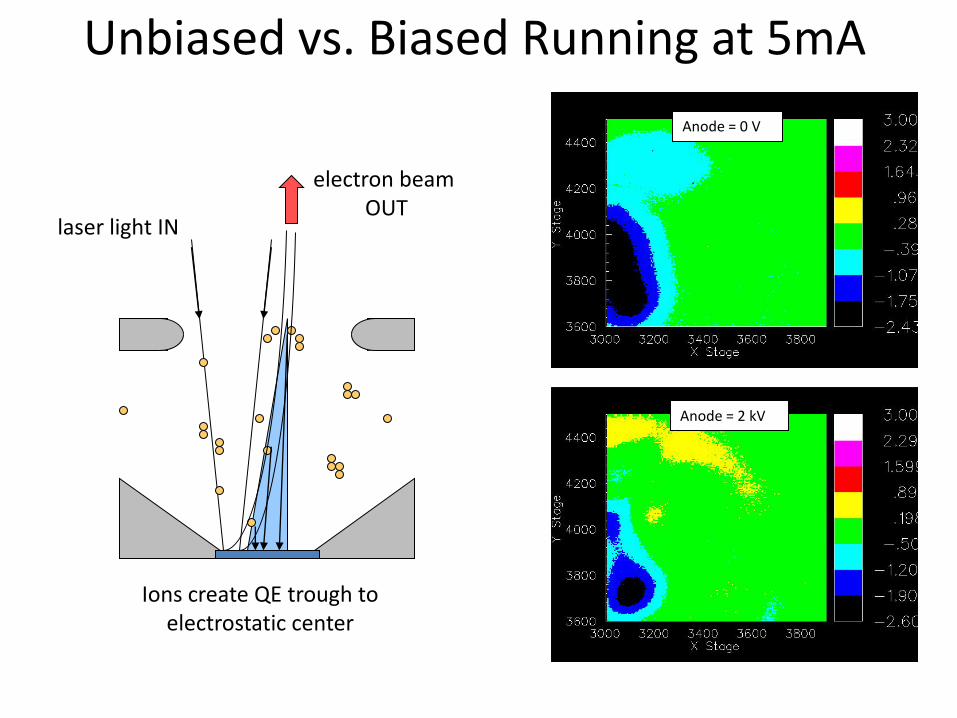
Unbiased vs. Biased Running at 5mA
Anode = 0 V
Anode = 2 kV
electron beam OUT
laser light IN
Ions create QE trough to electrostatic center
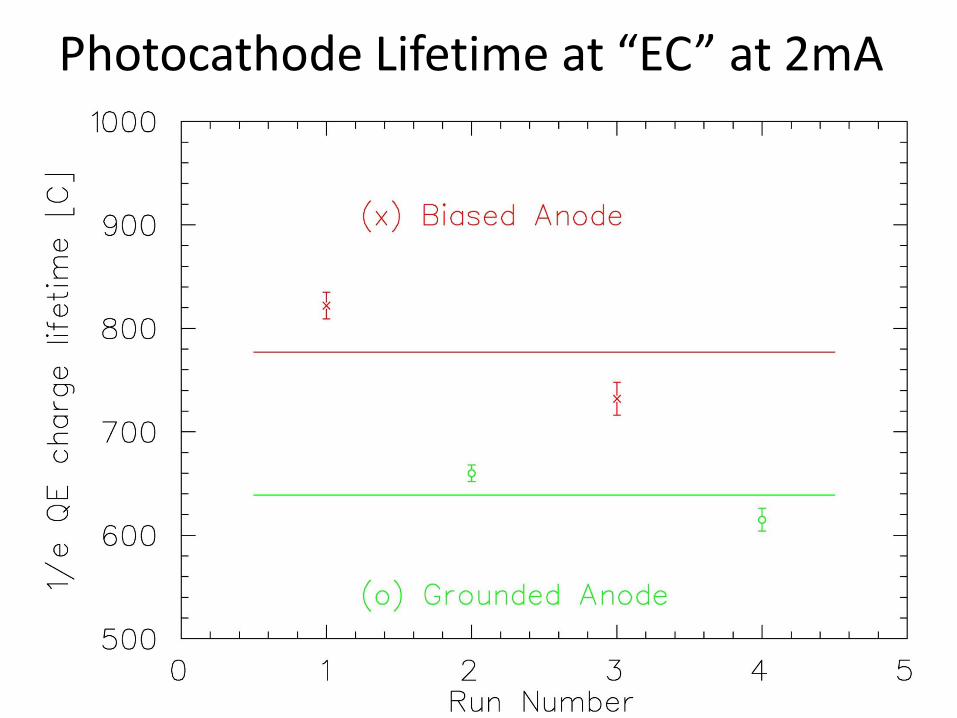
Photocathode Lifetime at “EC” at 2mA
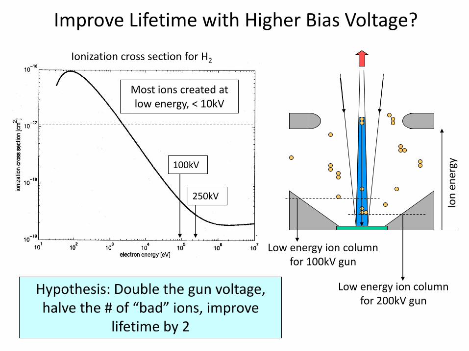
Improve Lifetime with Higher Bias Voltage?
Hypothesis: Double the gun voltage, halve the # of “bad” ions, improve
lifetime by 2
Ionization cross section for H2
100kV
250kV
Most ions created at low energy, < 10kV
Low energy ion column for 100kV gun
Low energy ion column for 200kV gun
Ion
en
ergy
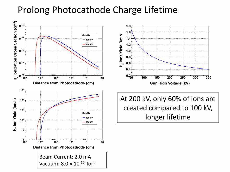
Prolong Photocathode Charge Lifetime
Beam Current: 2.0 mA Vacuum: 8.0 × 10⁻¹² Torr
At 200 kV, only 60% of ions are created compared to 100 kV,
longer lifetime
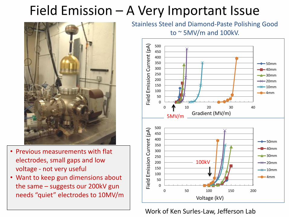
Field Emission – A Very Important Issue
• Previous measurements with flat electrodes, small gaps and low voltage - not very useful
• Want to keep gun dimensions about the same – suggests our 200kV gun needs “quiet” electrodes to 10MV/m
0
50
100
150
200
250
300
350
400
450
500
0 10 20 30 40
Fiel
d E
mis
sio
n C
urr
ent
(pA
)
Gradient (MV/m)
50mm
40mm
30mm
20mm
10mm
4mm
0
50
100
150
200
250
300
350
400
450
500
0 50 100 150 200
Fiel
d E
mis
sio
n C
urr
ent
(pA
)
Voltage (kV)
50mm
40mm
30mm
20mm
10mm
4mm
Stainless Steel and Diamond-Paste Polishing Good to ~ 5MV/m and 100kV.
Work of Ken Surles-Law, Jefferson Lab
5MV/m
100kV
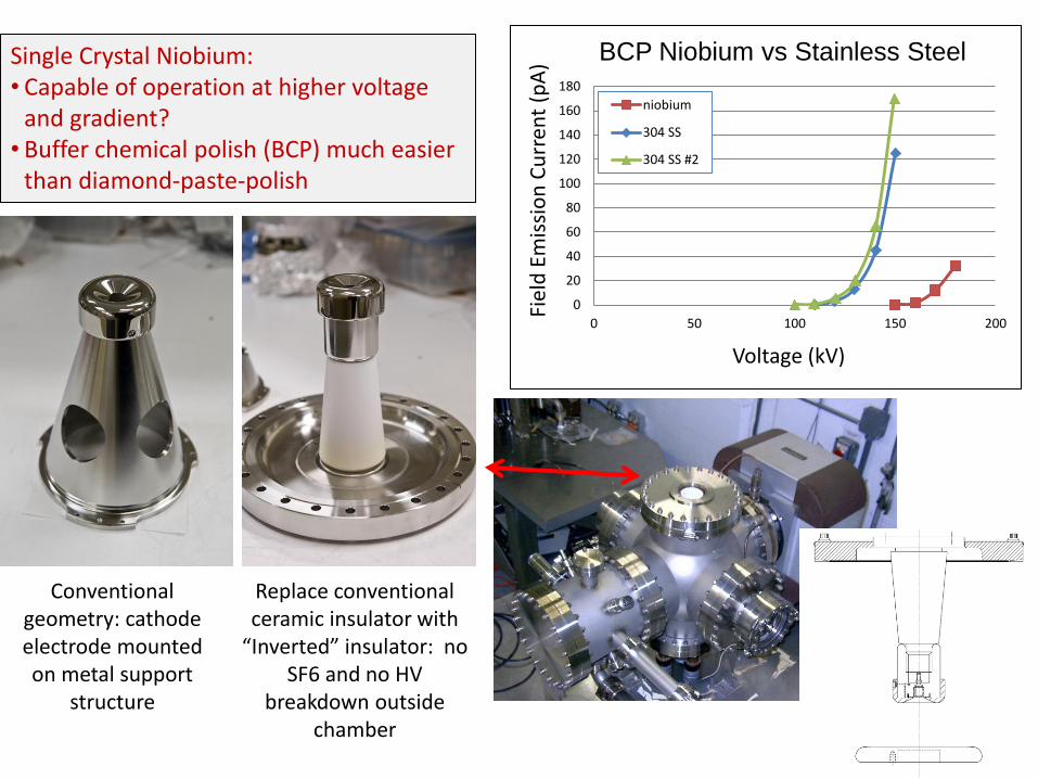
Single Crystal Niobium: • Capable of operation at higher voltage
and gradient? • Buffer chemical polish (BCP) much easier
than diamond-paste-polish
0
20
40
60
80
100
120
140
160
180
0 50 100 150 200
Fiel
d E
mis
sio
n C
urr
ent
(pA
)
Voltage (kV)
BCP Niobium vs Stainless Steel
niobium
304 SS
304 SS #2
Replace conventional ceramic insulator with
“Inverted” insulator: no SF6 and no HV
breakdown outside chamber
Conventional geometry: cathode electrode mounted on metal support
structure
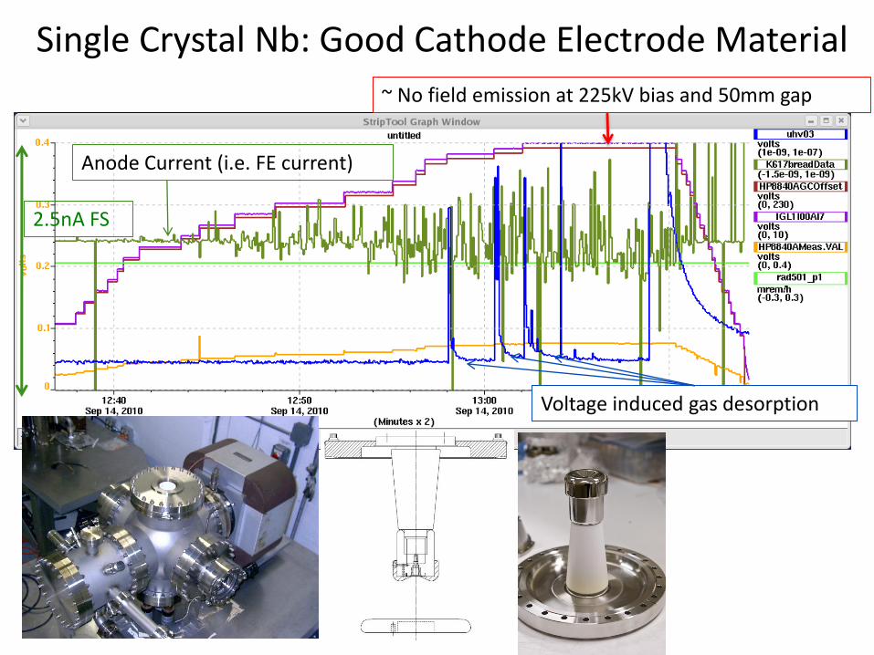
Single Crystal Nb: Good Cathode Electrode Material
~ No field emission at 225kV bias and 50mm gap
Voltage induced gas desorption
Anode Current (i.e. FE current)
2.5nA FS
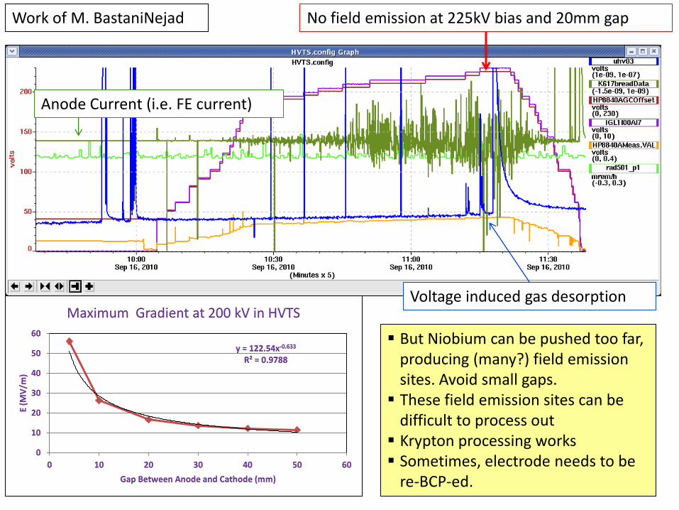
No field emission at 225kV bias and 20mm gap
Voltage induced gas desorption
Anode Current (i.e. FE current)
y = 122.54x-0.633 R² = 0.9788
0
10
20
30
40
50
60
0 10 20 30 40 50 60
E (M
V/m
)
Gap Between Anode and Cathode (mm)
Maximum Gradient at 200 kV in HVTS
But Niobium can be pushed too far, producing (many?) field emission sites. Avoid small gaps. These field emission sites can be
difficult to process out Krypton processing works Sometimes, electrode needs to be
re-BCP-ed.
Work of M. BastaniNejad
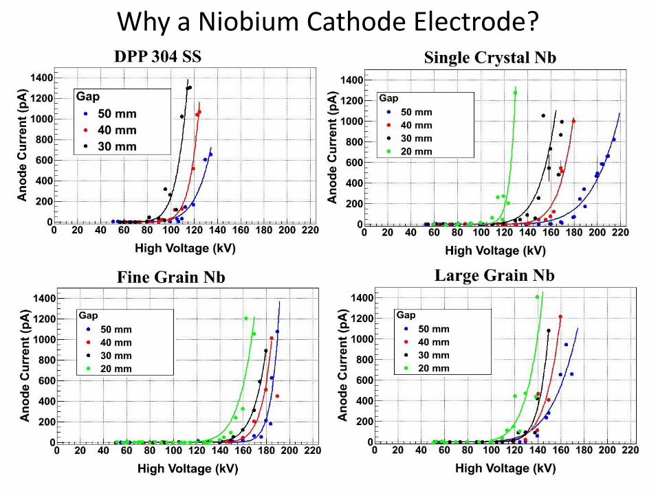
Why a Niobium Cathode Electrode?
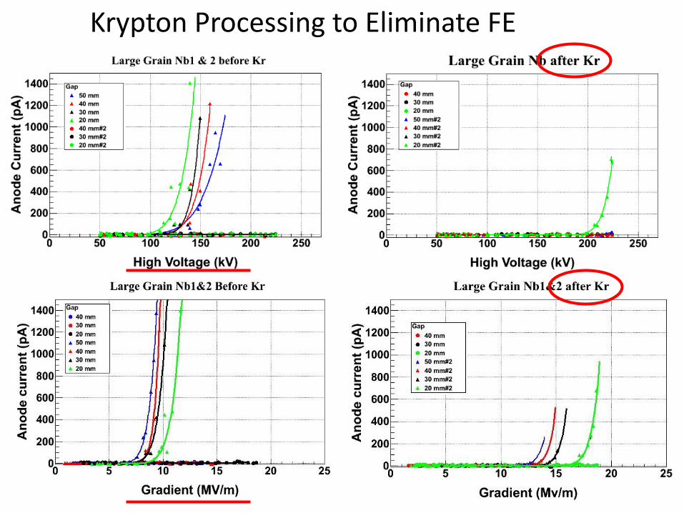
Krypton Processing to Eliminate FE
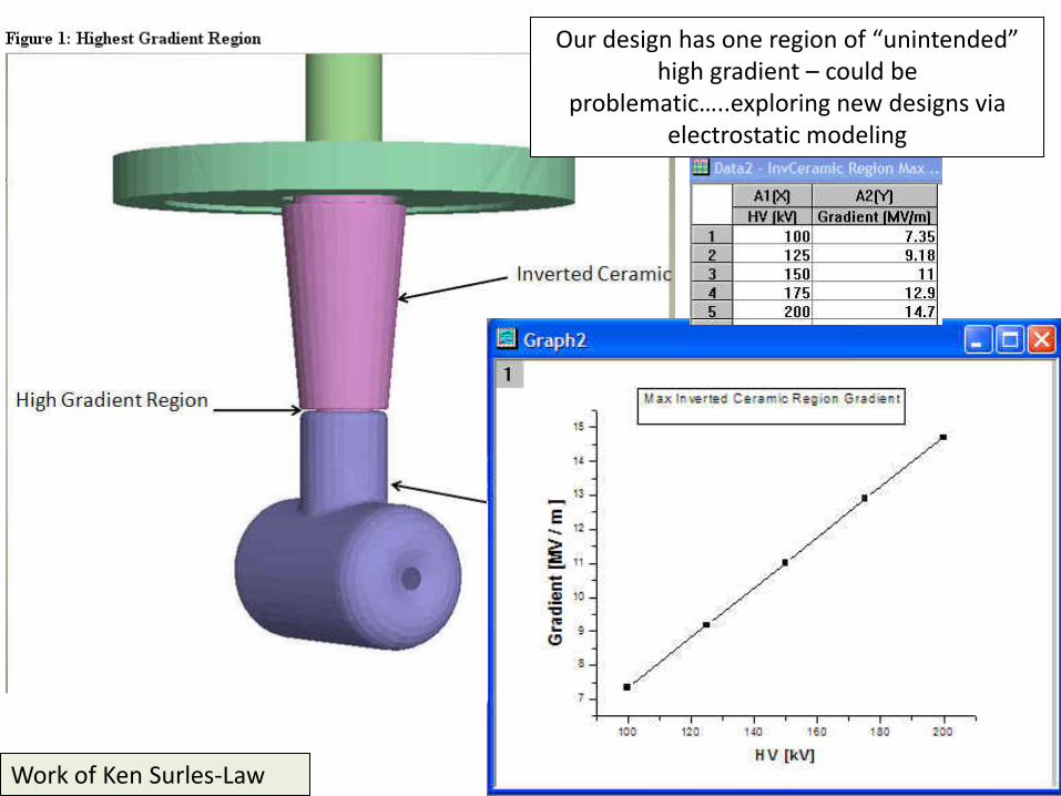
Our design has one region of “unintended” high gradient – could be
problematic…..exploring new designs via electrostatic modeling
Work of Ken Surles-Law
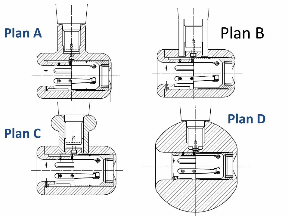
Plan A
Plan D Plan C
Plan B
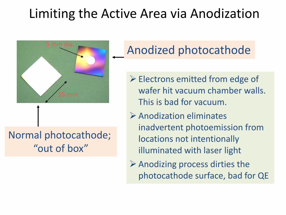
Limiting the Active Area via Anodization
Anodized photocathode
Normal photocathode; “out of box”
Electrons emitted from edge of wafer hit vacuum chamber walls. This is bad for vacuum.
Anodization eliminates inadvertent photoemission from locations not intentionally illuminated with laser light
Anodizing process dirties the photocathode surface, bad for QE
15 mm
5 mm dia.
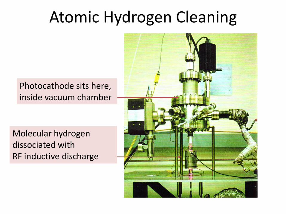
Atomic Hydrogen Cleaning
Molecular hydrogen dissociated with RF inductive discharge
Photocathode sits here, inside vacuum chamber
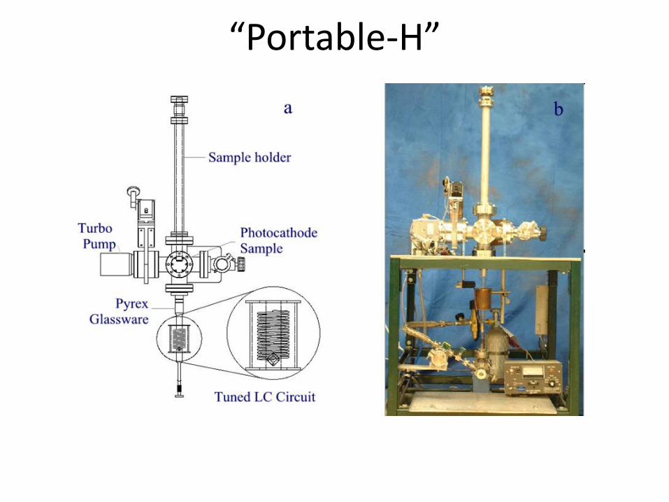
“Portable-H”
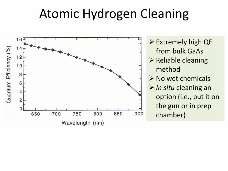
Atomic Hydrogen Cleaning
Extremely high QE from bulk GaAs
Reliable cleaning method
No wet chemicals In situ cleaning an
option (i.e., put it on the gun or in prep chamber)
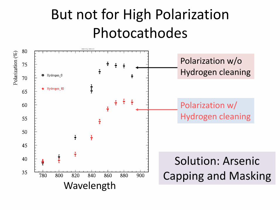
But not for High Polarization Photocathodes
Wavelength
Polarization w/o Hydrogen cleaning
Polarization w/ Hydrogen cleaning
Solution: Arsenic Capping and Masking
Deep UHV gauges Theory and Practice
Marcy Stutzman .
Bruce Kendall Elvac Laboratories
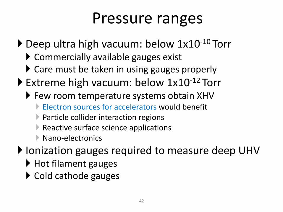
Pressure ranges
Deep ultra high vacuum: below 1x10⁻¹⁰ Torr Commercially available gauges exist Care must be taken in using gauges properly
Extreme high vacuum: below 1x10-12 Torr Few room temperature systems obtain XHV Electron sources for accelerators would benefit Particle collider interaction regions Reactive surface science applications Nano-electronics
Ionization gauges required to measure deep UHV Hot filament gauges Cold cathode gauges
42
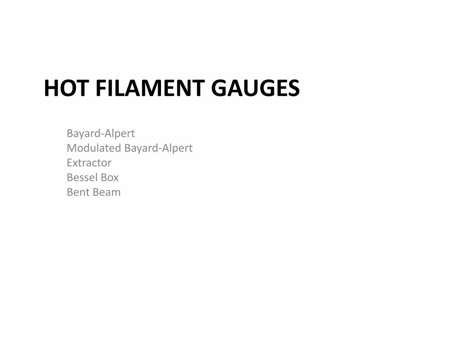
HOT FILAMENT GAUGES
Bayard-Alpert Modulated Bayard-Alpert Extractor Bessel Box Bent Beam
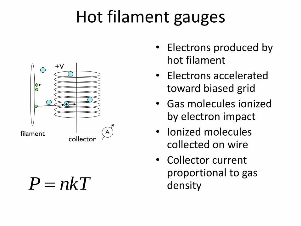
Hot filament gauges
• Electrons produced by hot filament
• Electrons accelerated toward biased grid
• Gas molecules ionized by electron impact
• Ionized molecules collected on wire
• Collector current proportional to gas density
A filament
+V
collector
+
nkTP
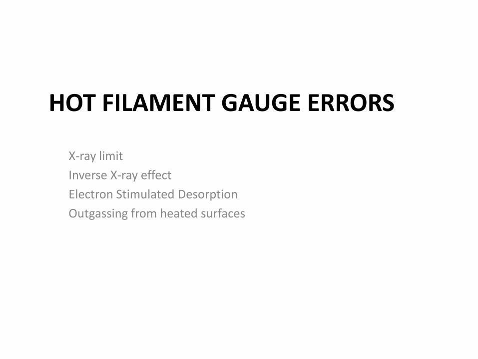
HOT FILAMENT GAUGE ERRORS
X-ray limit
Inverse X-ray effect
Electron Stimulated Desorption
Outgassing from heated surfaces
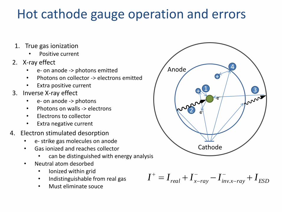
ESDrayxinvrayxreal IIIII
.
1. True gas ionization • Positive current
Cathode
Anode
1 + 3 e-
2 e-
2. X-ray effect • e- on anode -> photons emitted • Photons on collector -> electrons emitted • Extra positive current
3. Inverse X-ray effect • e- on anode -> photons • Photons on walls -> electrons • Electrons to collector • Extra negative current
4
+
4. Electron stimulated desorption • e- strike gas molecules on anode • Gas ionized and reaches collector
• can be distinguished with energy analysis • Neutral atom desorbed
• Ionized within grid • Indistinguishable from real gas • Must eliminate souce
Hot cathode gauge operation and errors
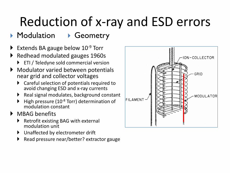
Reduction of x-ray and ESD errors
Extends BA gauge below 10-9 Torr Redhead modulated gauges 1960s ETI / Teledyne sold commercial version
Modulator varied between potentials near grid and collector voltages Careful selection of potentials required to
avoid changing ESD and x-ray currents Real signal modulates, background constant High pressure (10-8 Torr) determination of
modulation constant
MBAG benefits Retrofit existing BAG with external
modulation unit Unaffected by electrometer drift Read pressure near/better? extractor gauge
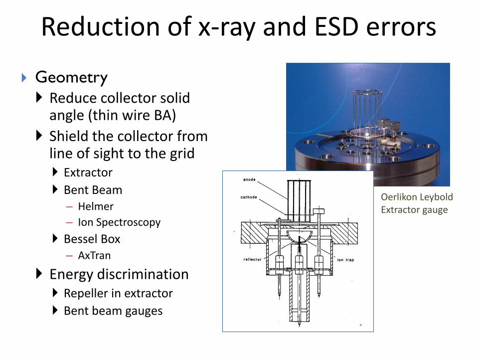
Geometry
Modulation
Reduction of x-ray and ESD errors
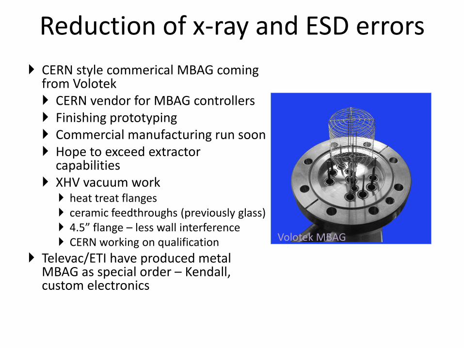
CERN style commerical MBAG coming from Volotek CERN vendor for MBAG controllers Finishing prototyping Commercial manufacturing run soon Hope to exceed extractor
capabilities XHV vacuum work
heat treat flanges ceramic feedthroughs (previously glass) 4.5” flange – less wall interference CERN working on qualification
Televac/ETI have produced metal MBAG as special order – Kendall, custom electronics
Volotek MBAG
Reduction of x-ray and ESD errors
Reduce collector solid angle (thin wire BA)
Shield the collector from line of sight to the grid Extractor
Bent Beam – Helmer
– Ion Spectroscopy
Bessel Box – AxTran
Energy discrimination Repeller in extractor
Bent beam gauges
Geometry
Oerlikon Leybold Extractor gauge
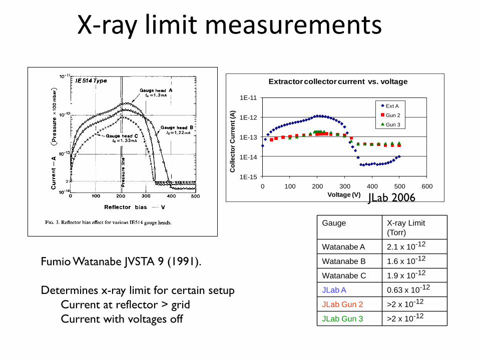
X-ray limit measurements
Fumio Watanabe JVSTA 9 (1991).
Determines x-ray limit for certain setup
Current at reflector > grid
Current with voltages off
1E-15
1E-14
1E-13
1E-12
1E-11
0 100 200 300 400 500 600
Co
lle
cto
r C
urr
en
t (A
)
Voltage (V)
Extractor collector current vs. voltage
Ext A
Gun 2
Gun 3
JLab 2006
Gauge X-ray Limit
(Torr)
Watanabe A 2.1 x 10⁻¹²
Watanabe B 1.6 x 10⁻¹²
Watanabe C 1.9 x 10⁻¹²
JLab A 0.63 x 10⁻¹²
JLab Gun 2 >2 x 10-12
JLab Gun 3 >2 x 10-12
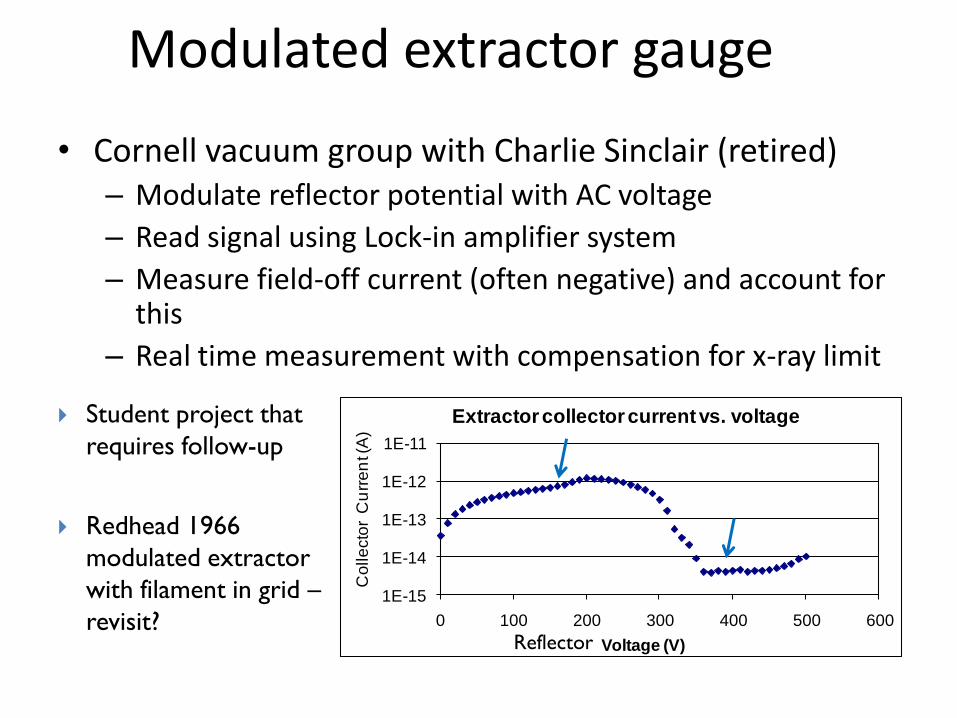
Modulated extractor gauge
• Cornell vacuum group with Charlie Sinclair (retired) – Modulate reflector potential with AC voltage
– Read signal using Lock-in amplifier system
– Measure field-off current (often negative) and account for this
– Real time measurement with compensation for x-ray limit
1E-15
1E-14
1E-13
1E-12
1E-11
0 100 200 300 400 500 600
Co
lle
cto
r C
urr
en
t (A
)
Voltage (V)
Extractor collector current vs. voltage
Reflector
Student project that
requires follow-up
Redhead 1966
modulated extractor
with filament in grid –
revisit?
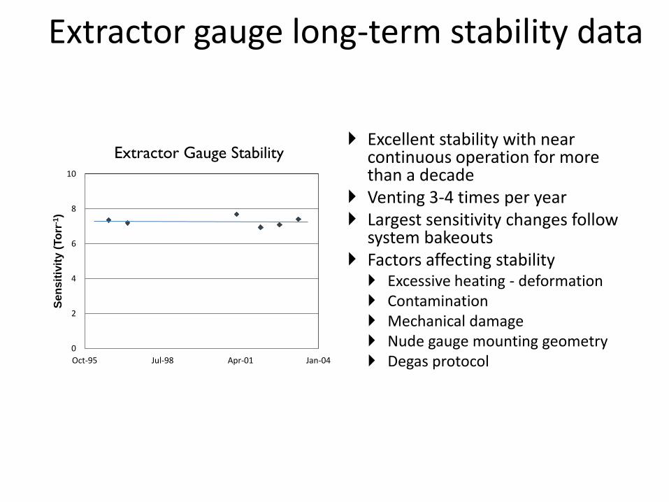
Extractor gauge long-term stability data
Excellent stability with near continuous operation for more than a decade
Venting 3-4 times per year Largest sensitivity changes follow
system bakeouts Factors affecting stability Excessive heating - deformation Contamination Mechanical damage Nude gauge mounting geometry Degas protocol
0
2
4
6
8
10
Oct-95 Jul-98 Apr-01 Jan-04
Se
nsit
ivit
y (
To
rr-1
)
Extractor Gauge Stability
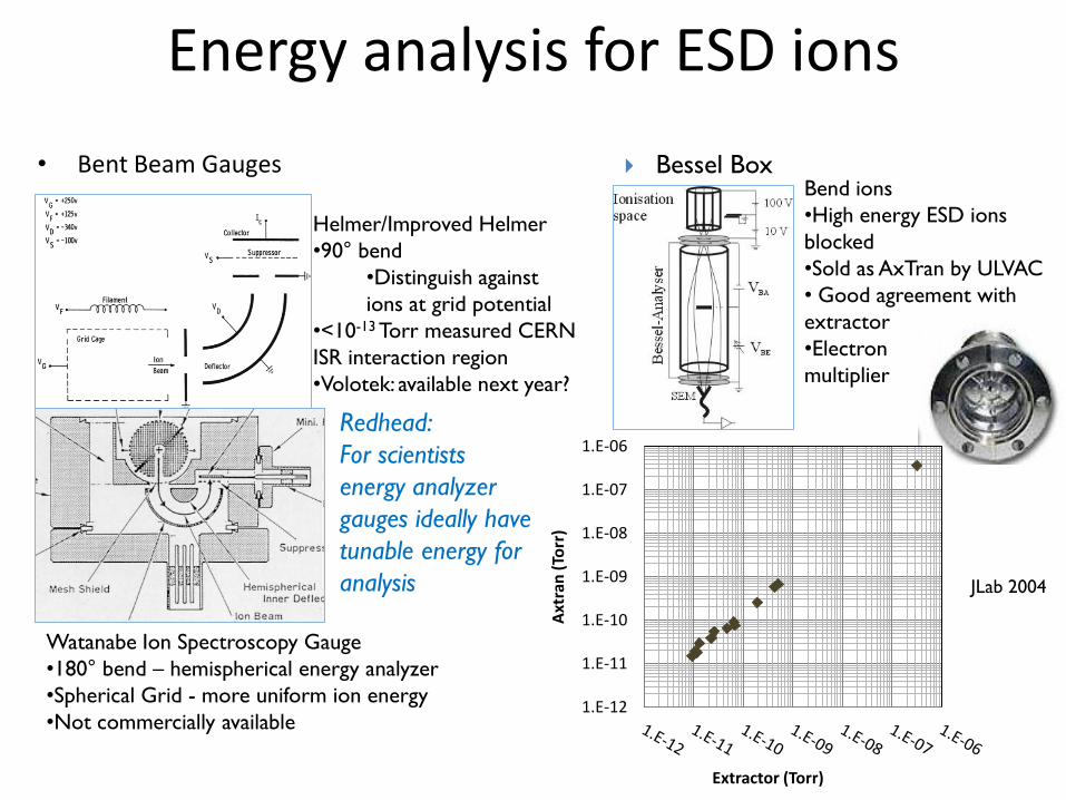
Energy analysis for ESD ions
• Bent Beam Gauges
Helmer/Improved Helmer
•90° bend
•Distinguish against
ions at grid potential
•<10-13 Torr measured CERN
ISR interaction region
•Volotek: available next year?
Watanabe Ion Spectroscopy Gauge
•180° bend – hemispherical energy analyzer
•Spherical Grid - more uniform ion energy
•Not commercially available
Bend ions
•High energy ESD ions
blocked
•Sold as AxTran by ULVAC
• Good agreement with
extractor
•Electron
multiplier
Bessel Box
Redhead:
For scientists
energy analyzer
gauges ideally have
tunable energy for
analysis JLab 2004
1.E-12
1.E-11
1.E-10
1.E-09
1.E-08
1.E-07
1.E-06
Axt
ran
(To
rr)
Extractor (Torr)
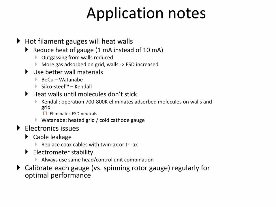
Application notes
Hot filament gauges will heat walls Reduce heat of gauge (1 mA instead of 10 mA)
Outgassing from walls reduced More gas adsorbed on grid, walls -> ESD increased
Use better wall materials BeCu – Watanabe Silco-steel™ – Kendall
Heat walls until molecules don’t stick Kendall: operation 700-800K eliminates adsorbed molecules on walls and
grid Eliminates ESD neutrals
Watanabe: heated grid / cold cathode gauge
Electronics issues Cable leakage
Replace coax cables with twin-ax or tri-ax
Electrometer stability Always use same head/control unit combination
Calibrate each gauge (vs. spinning rotor gauge) regularly for optimal performance
COLD CATHODE GAUGES
Magnetron
Inverted Magnetron
Double Inverted Magnetron
Ion pump?
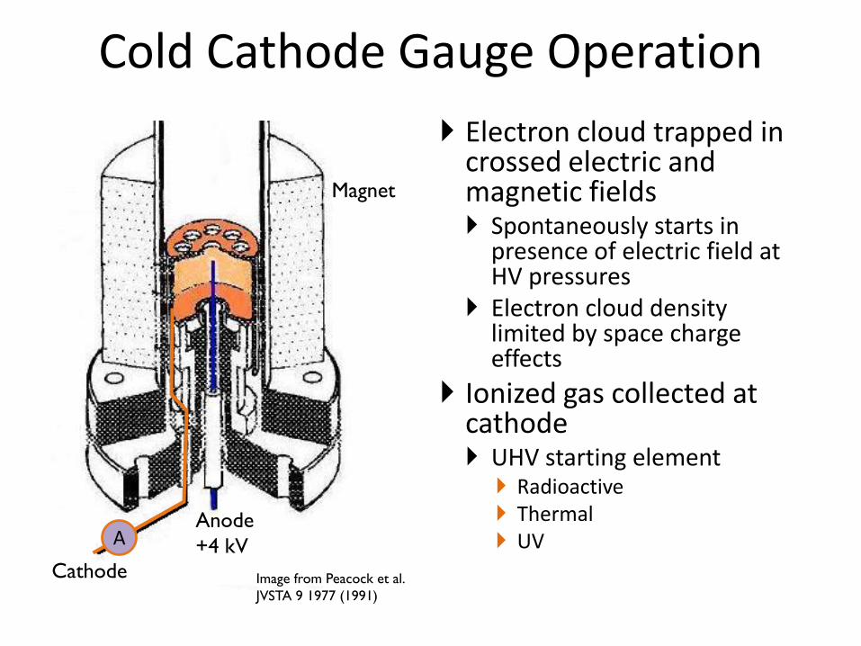
Cold Cathode Gauge Operation
Electron cloud trapped in crossed electric and magnetic fields Spontaneously starts in
presence of electric field at HV pressures
Electron cloud density limited by space charge effects
Ionized gas collected at cathode UHV starting element
Radioactive Thermal UV
Magnet
Anode
+4 kV
Cathode
A
Image from Peacock et al.
JVSTA 9 1977 (1991)
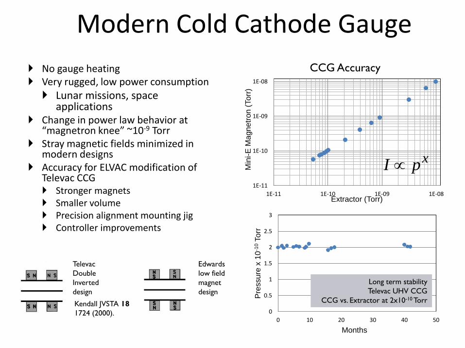
Modern Cold Cathode Gauge
No gauge heating Very rugged, low power consumption
Lunar missions, space applications
Change in power law behavior at “magnetron knee” ~10-9 Torr
Stray magnetic fields minimized in modern designs
Accuracy for ELVAC modification of Televac CCG Stronger magnets Smaller volume Precision alignment mounting jig Controller improvements
0
0.5
1
1.5
2
2.5
3
0 10 20 30 40 50
Pre
ssu
re x
10
-10 T
orr
Months
Long term stability
Televac UHV CCG
CCG vs. Extractor at 2x10⁻¹⁰ Torr
CCG Accuracy
1E-11
1E-10
1E-09
1E-08
1E-11 1E-10 1E-09 1E-08
Min
i-E
Ma
gn
etr
on
(To
rr)
Extractor (Torr)
Kendall JVSTA 18
1724 (2000).
Edwards
low field
magnet
design
Televac
Double
Inverted
design
xpI
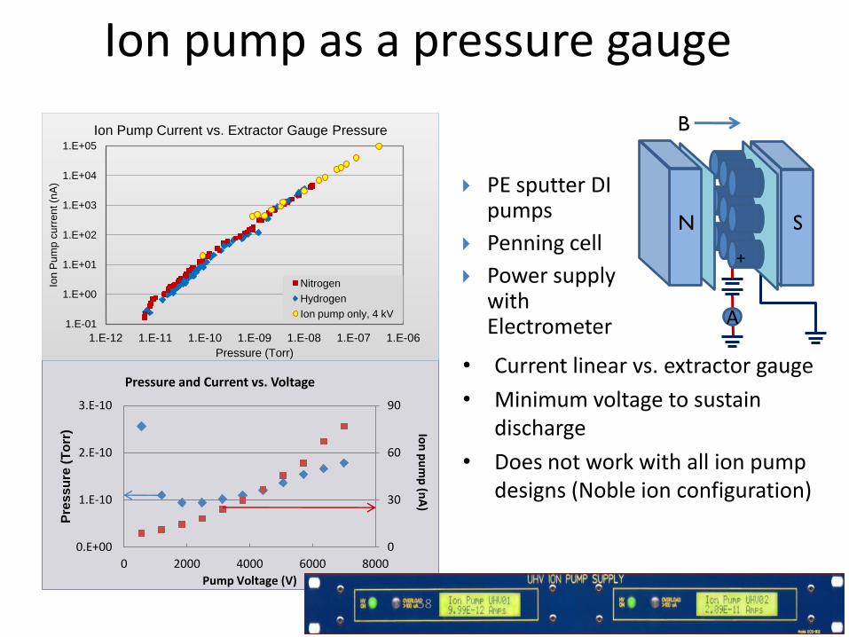
Ion pump as a pressure gauge
• Current linear vs. extractor gauge
• Minimum voltage to sustain discharge
• Does not work with all ion pump designs (Noble ion configuration)
0
30
60
90
0.E+00
1.E-10
2.E-10
3.E-10
0 2000 4000 6000 8000
Pre
ss
ure
(T
orr
)
Pump Voltage (V)
Pressure and Current vs. Voltage
Ion
pu
mp
(nA
)
1.E-01
1.E+00
1.E+01
1.E+02
1.E+03
1.E+04
1.E+05
1.E-12 1.E-11 1.E-10 1.E-09 1.E-08 1.E-07 1.E-06
Ion
Pu
mp
cu
rre
nt (n
A)
Pressure (Torr)
Ion Pump Current vs. Extractor Gauge Pressure
Nitrogen
Hydrogen
Ion pump only, 4 kV
58
B
A
PE sputter DI pumps
Penning cell
Power supply with Electrometer
N S
+
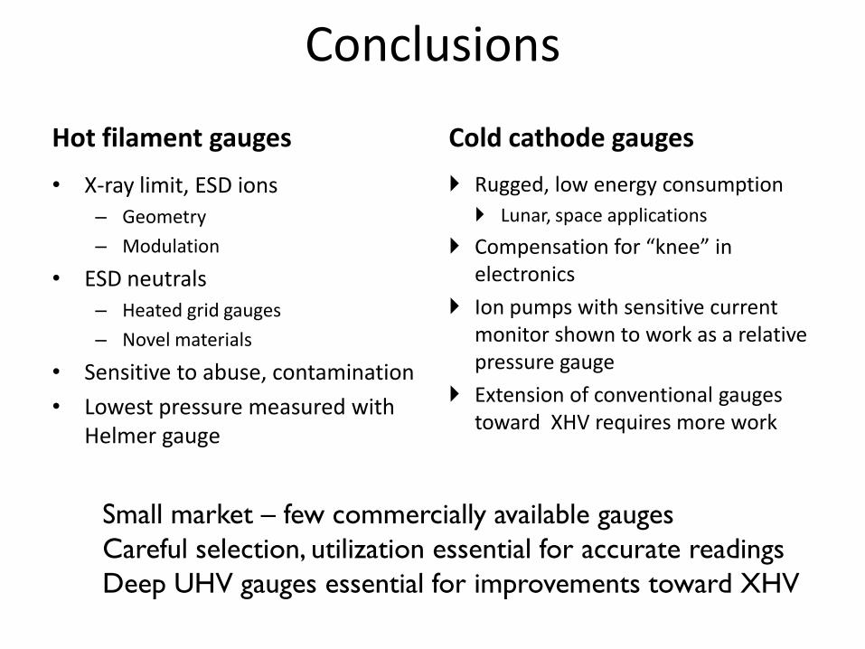
Conclusions
Hot filament gauges Cold cathode gauges
• X-ray limit, ESD ions
– Geometry
– Modulation
• ESD neutrals
– Heated grid gauges
– Novel materials
• Sensitive to abuse, contamination
• Lowest pressure measured with Helmer gauge
Rugged, low energy consumption
Lunar, space applications
Compensation for “knee” in electronics
Ion pumps with sensitive current monitor shown to work as a relative pressure gauge
Extension of conventional gauges toward XHV requires more work
Small market – few commercially available gauges
Careful selection, utilization essential for accurate readings
Deep UHV gauges essential for improvements toward XHV
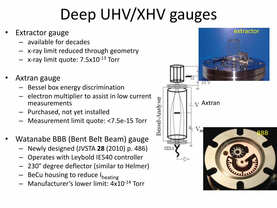
Deep UHV/XHV gauges • Extractor gauge
– available for decades – x-ray limit reduced through geometry – x-ray limit quote: 7.5x10⁻¹³ Torr
• Axtran gauge – Bessel box energy discrimination – electron multiplier to assist in low current
measurements – Purchased, not yet installed – Measurement limit quote: <7.5e-15 Torr
• Watanabe BBB (Bent Belt Beam) gauge – Newly designed (JVSTA 28 (2010) p. 486) – Operates with Leybold IE540 controller – 230° degree deflector (similar to Helmer) – BeCu housing to reduce Iheating – Manufacturer’s lower limit: 4x10-14 Torr
extractor
BBB
Axtran
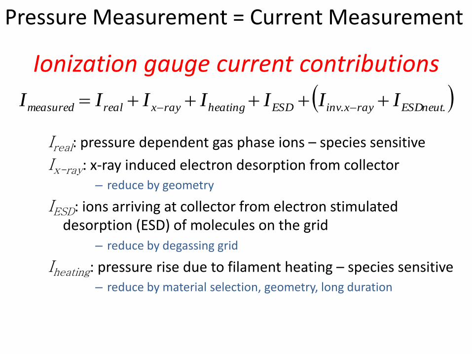
Ionization gauge current contributions
Ireal: pressure dependent gas phase ions – species sensitive
Ix-ray: x-ray induced electron desorption from collector – reduce by geometry
IESD: ions arriving at collector from electron stimulated desorption (ESD) of molecules on the grid
– reduce by degassing grid
Iheating: pressure rise due to filament heating – species sensitive – reduce by material selection, geometry, long duration
.. neutESDrayxinvESDheatingrayxrealmeasured IIIIIII
Pressure Measurement = Current Measurement
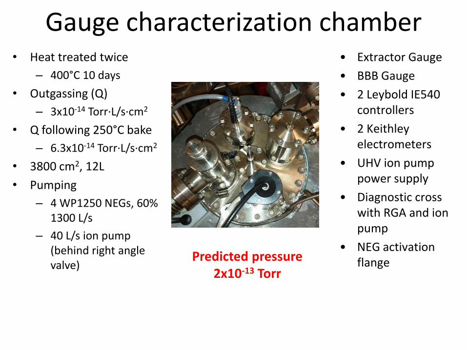
Gauge characterization chamber • Heat treated twice
– 400°C 10 days
• Outgassing (Q)
– 3x10-14 Torr·L/s·cm2
• Q following 250°C bake
– 6.3x10⁻¹⁴ Torr·L/s·cm2
• 3800 cm2, 12L
• Pumping
– 4 WP1250 NEGs, 60% 1300 L/s
– 40 L/s ion pump (behind right angle valve)
• Extractor Gauge
• BBB Gauge
• 2 Leybold IE540 controllers
• 2 Keithley electrometers
• UHV ion pump power supply
• Diagnostic cross with RGA and ion pump
• NEG activation flange Predicted pressure
2x10-13 Torr
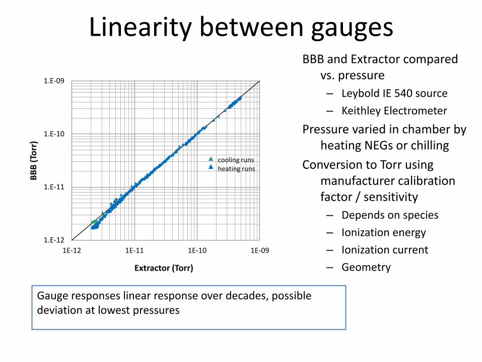
Linearity between gauges
1.E-12
1.E-11
1.E-10
1.E-09
1E-12 1E-11 1E-10 1E-09
BB
B (
Torr
)
Extractor (Torr)
cooling runs heating runs
BBB and Extractor compared vs. pressure
– Leybold IE 540 source
– Keithley Electrometer
Pressure varied in chamber by heating NEGs or chilling
Conversion to Torr using manufacturer calibration factor / sensitivity
– Depends on species
– Ionization energy
– Ionization current
– Geometry
Gauge responses linear response over decades, possible deviation at lowest pressures
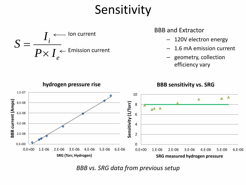
Sensitivity
e
i
IP
IS
Ion current
Emission current
0.E+00
2.E-08
4.E-08
6.E-08
8.E-08
1.E-07
0.E+00 1.E-06 2.E-06 3.E-06 4.E-06 5.E-06 6.E-06
BB
B c
urr
en
t (A
mp
s)
SRG (Torr, Hydrogen)
hydrogen pressure rise
0
2
4
6
8
10
0.E+00 1.E-06 2.E-06 3.E-06 4.E-06 5.E-06 6.E-06
Sen
siti
vity
(1
/To
rr)
SRG measured hydrogen pressure
BBB sensitivity vs. SRG
BBB and Extractor
– 120V electron energy
– 1.6 mA emission current
– geometry, collection efficiency vary
BBB vs. SRG data from previous setup
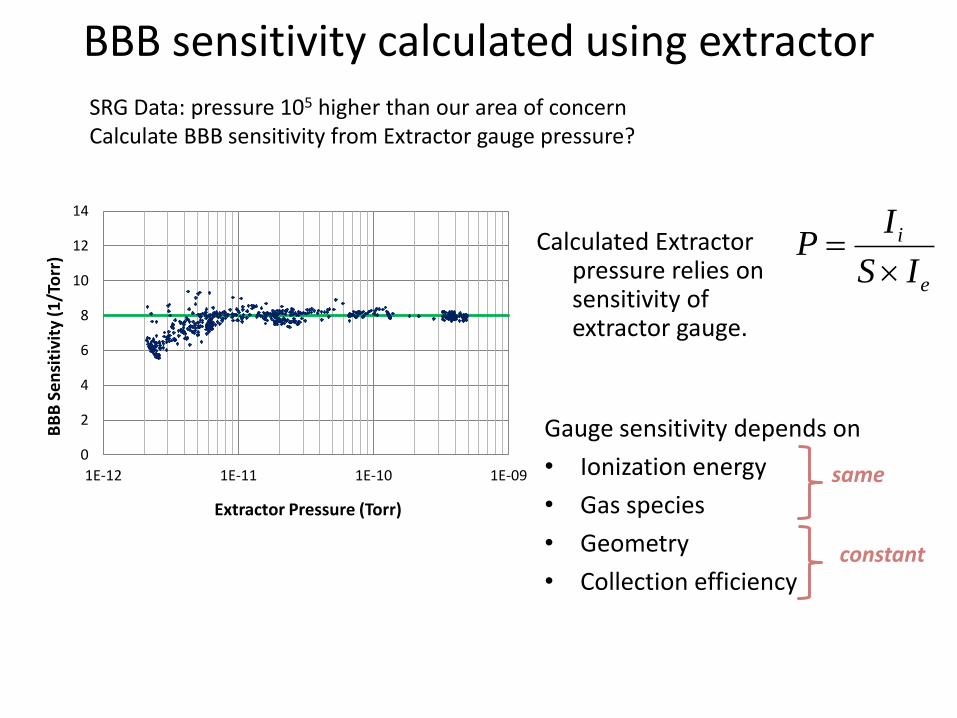
BBB sensitivity calculated using extractor
0
2
4
6
8
10
12
14
1E-12 1E-11 1E-10 1E-09
BB
B S
en
siti
vity
(1
/To
rr)
Extractor Pressure (Torr)
SRG Data: pressure 105 higher than our area of concern Calculate BBB sensitivity from Extractor gauge pressure?
Calculated Extractor pressure relies on sensitivity of extractor gauge.
e
i
IS
IP
Gauge sensitivity depends on
• Ionization energy
• Gas species
• Geometry
• Collection efficiency
same
constant
relative sensitivity
0.0
0.2
0.4
0.6
0.8
1.0
1.2
1.4
1.6
1.E-14 1.E-13 1.E-12 1.E-11
S(B
BB
) /
S(Ex
t.)
Extractor current (Amps)
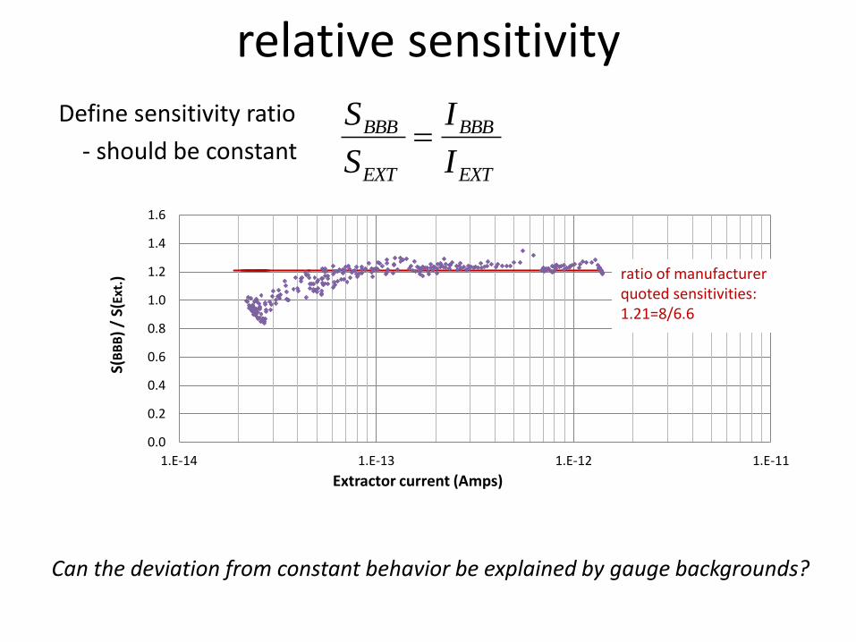
ratio of manufacturer quoted sensitivities: 1.21=8/6.6
Define sensitivity ratio
- should be constant EXT
BBB
EXT
BBB
I
I
S
S
Can the deviation from constant behavior be explained by gauge backgrounds?
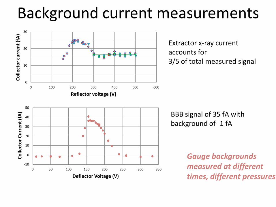
Background current measurements
0
10
20
30
0 100 200 300 400 500 600
Co
llect
or
curr
en
t (f
A)
Reflector voltage (V)
Extractor x-ray current accounts for 3/5 of total measured signal
BBB signal of 35 fA with background of -1 fA
-10
0
10
20
30
40
50
0 50 100 150 200 250 300 350
Co
llect
or
Cu
rre
nt
(fA
)
Deflector Voltage (V)
Gauge backgrounds measured at different times, different pressures
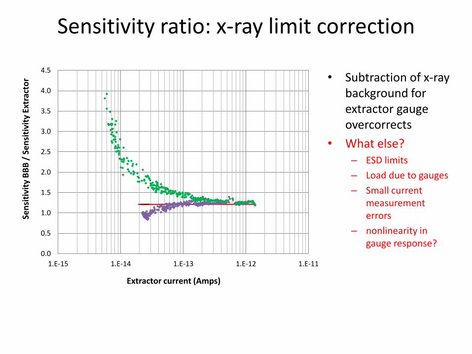
Sensitivity ratio: x-ray limit correction
0.0
0.5
1.0
1.5
2.0
2.5
3.0
3.5
4.0
4.5
1.E-15 1.E-14 1.E-13 1.E-12 1.E-11
Sen
siti
vity
BB
B /
Se
nsi
tivi
ty E
xtra
cto
r
Extractor current (Amps)
• Subtraction of x-ray background for extractor gauge overcorrects
• What else? – ESD limits
– Load due to gauges
– Small current measurement errors
– nonlinearity in gauge response?
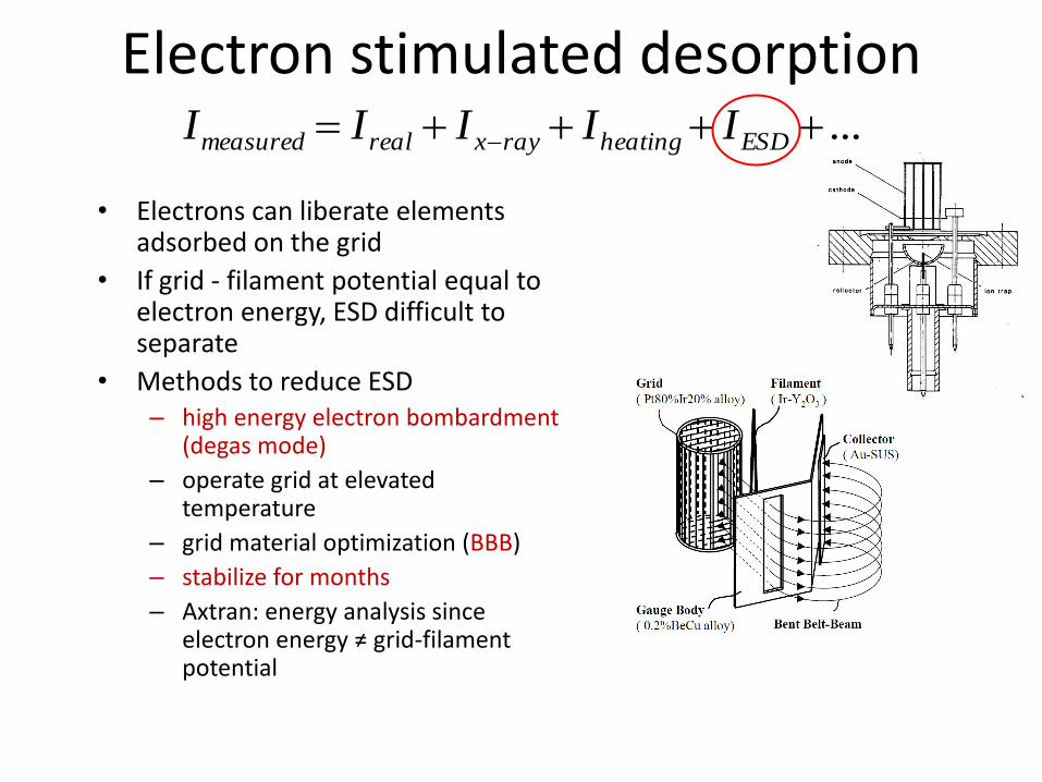
Electron stimulated desorption
• Electrons can liberate elements adsorbed on the grid
• If grid - filament potential equal to electron energy, ESD difficult to separate
• Methods to reduce ESD – high energy electron bombardment
(degas mode)
– operate grid at elevated temperature
– grid material optimization (BBB)
– stabilize for months
– Axtran: energy analysis since electron energy ≠ grid-filament potential
... ESDheatingrayxrealmeasured IIIII
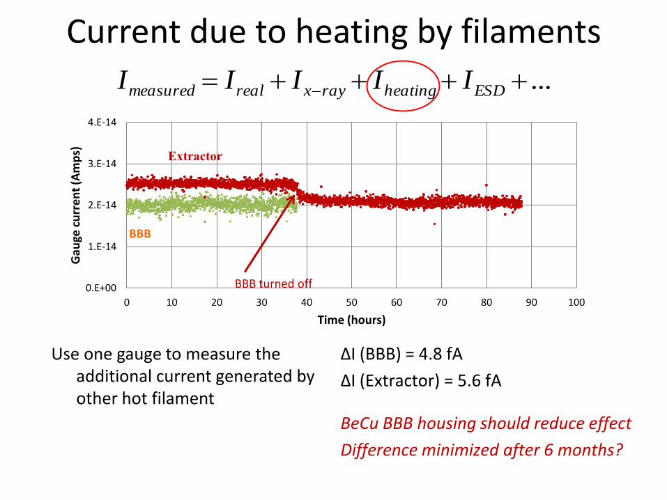
Current due to heating by filaments
Use one gauge to measure the additional current generated by other hot filament
... ESDheatingrayxrealmeasured IIIII
0.E+00
1.E-14
2.E-14
3.E-14
4.E-14
0 10 20 30 40 50 60 70 80 90 100
Gau
ge c
urr
en
t (A
mp
s)
Time (hours)
BBB turned off
BBB
Extractor
ΔI (BBB) = 4.8 fA
ΔI (Extractor) = 5.6 fA
BeCu BBB housing should reduce effect
Difference minimized after 6 months?
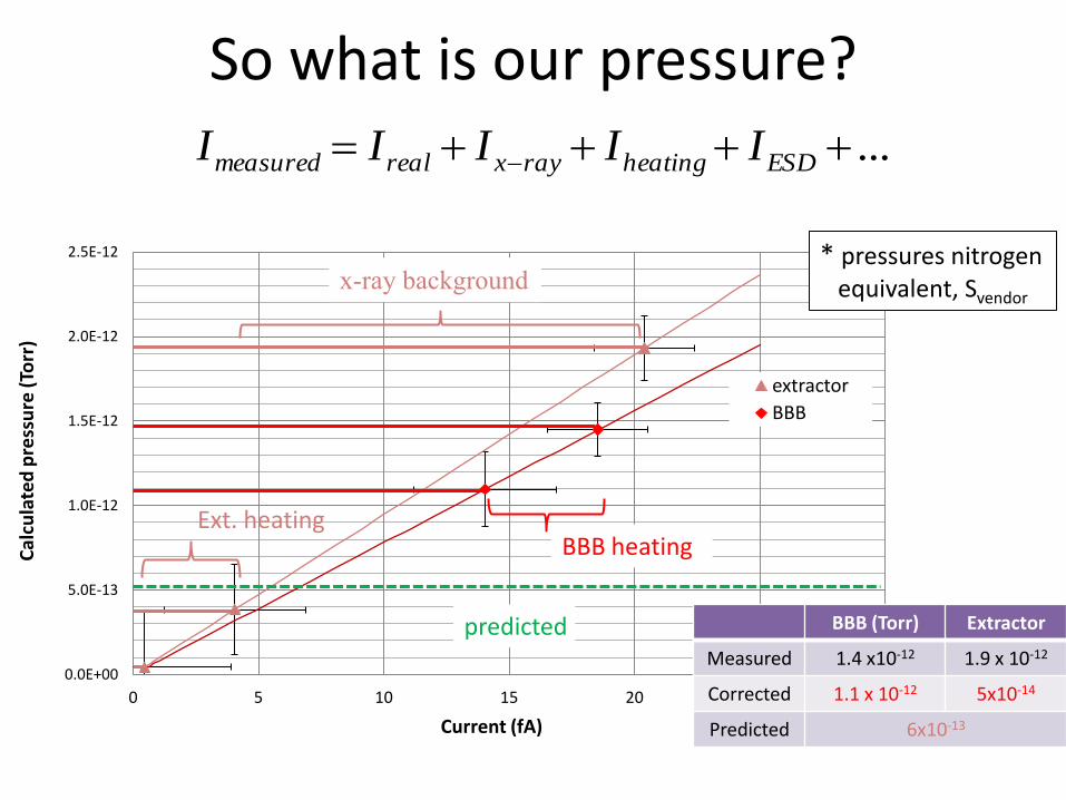
So what is our pressure?
0.0E+00
5.0E-13
1.0E-12
1.5E-12
2.0E-12
2.5E-12
0 5 10 15 20 25 30
Cal
cula
ted
pre
ssu
re (
Torr
)
Current (fA)
extractor
BBB
x-ray background
BBB heating Ext. heating
... ESDheatingrayxrealmeasured IIIII
predicted BBB (Torr) Extractor
Measured 1.4 x10⁻¹² 1.9 x 10⁻¹²
Corrected 1.1 x 10⁻¹² 5x10-14
Predicted 6x10-13
* pressures nitrogen equivalent, Svendor
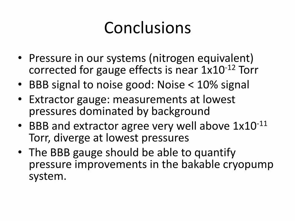
Conclusions
• Pressure in our systems (nitrogen equivalent) corrected for gauge effects is near 1x10-12 Torr
• BBB signal to noise good: Noise < 10% signal • Extractor gauge: measurements at lowest
pressures dominated by background • BBB and extractor agree very well above 1x10-11
Torr, diverge at lowest pressures • The BBB gauge should be able to quantify
pressure improvements in the bakable cryopump system.
Back up slides
Emittance and Brightness
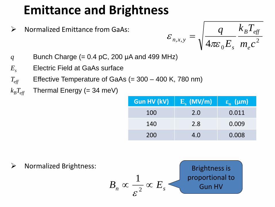
Normalized Emittance from GaAs:
2
0
,,4 cm
Tk
E
q
e
effB
s
yxn
q Bunch Charge (= 0.4 pC, 200 μA and 499 MHz)
Es Electric Field at GaAs surface
Teff Effective Temperature of GaAs (= 300 – 400 K, 780 nm)
kBTeff Thermal Energy (= 34 meV)
Normalized Brightness:
sn EB 2
1
Brightness is proportional to
Gun HV
Gun HV (kV) Es (MV/m) εn (μm)
100 2.0 0.011
140 2.8 0.009
200 4.0 0.008
Work of Riad Suleiman
• 13 mm • 7 mm • 5 mm
Now we mask…
DC beam from bulk GaAs, green light and 350um spot. Similar (good) results as with older guns, at 100kV
Finite lifetime due to ion back-bombardment
InvGun2 : Lifetime at 2mA and 100kV bias: Versus Laser Position and Active Area