Using the New Verilog-2001 Standard, Part 2Using the New Verilog-2001 Standard Part 2: Verifying...
32
Using the New Verilog-2001 Standard Part 2: Verifying Hardware by Sutherland HDL, Inc., Portland, Oregon, 2001 Part 2-1 Using the New Verilog-2001 Standard Part Two: Verifying Designs by Stuart Sutherland Sutherland HDL, Inc. Portland, Oregon Part 2-2 L H D Sutherland All material in this presentation is copyrighted by Sutherland HDL, Inc., Portland, Oregon. All rights reserved. No material from this presentation may be duplicated or transmitted by any means or in any form without the express written permission of Sutherland HDL, Inc. copyright notice Sutherland HDL Incorporated 22805 SW 92 nd Place Tualatin, OR 97062 USA phone: (503) 692-0898 fax: (503) 692-1512 e-mail: [email protected] web: www.sutherland-hdl.com ©2001 Verilog is a registered trademark of Cadence Design Systems, San Jose, CA
Transcript of Using the New Verilog-2001 Standard, Part 2Using the New Verilog-2001 Standard Part 2: Verifying...

Using the New Verilog-2001 StandardPart 2: Verifying Hardware
by Sutherland HDL, Inc., Portland, Oregon, 2001
Part 2-1
Using the New Verilog-2001 StandardPart Two: Verifying Designs
by
Stuart SutherlandSutherland HDL, Inc.
Portland, Oregon
Part 2-2
LH D
Sutherland
All material in this presentation is copyrighted by Sutherland HDL, Inc., Portland, Oregon. All rights reserved. No material from this presentation may be duplicated or transmitted by any means or in any form without the express written permission of Sutherland HDL, Inc.
copyright notice
Sutherland HDL Incorporated22805 SW 92nd Place
Tualatin, OR 97062 USA
phone: (503) 692-0898fax: (503) 692-1512
e-mail: [email protected]: www.sutherland-hdl.com
©2001
Verilog is a registered trademark of Cadence Design Systems, San Jose, CA

Using the New Verilog-2001 StandardPart 2: Verifying Hardware
by Sutherland HDL, Inc., Portland, Oregon, 2001
Part 2-2
Part 2-3
LH D
SutherlandAbout Stuart Sutherlandand Sutherland HDL, Inc.
◆ Sutherland HDL, Inc. (founded 1992)◆ Provides expert Verilog HDL and PLI design services◆ Provides Verilog HDL and PLI Training ◆ Located near Portland Oregon, World-wide services
◆ Mr. Stuart Sutherland◆ Over 13 years experience with Verilog ◆ Worked as a design engineer on military flight simulators ◆ Senior Applications Engineer for Gateway Design
Automation, the founding company of Verilog◆ Author of the popular “Verilog HDL Quick Reference Guide”
and “The Verilog PLI Handbook”◆ Involved in the IEEE 1364 Verilog standardization
Part 2-4
LH D
SutherlandSeminar Objectives
◆ The focus of this seminar is on understanding what is new in the Verilog-2001 standard◆ An overview of the Verilog HDL◆ Details on the major enhancements in Verilog-2001◆ Ideas on how you can use these enhancements, today
◆ Assumptions:◆ You have a background in hardware engineering◆ You are at least familiar with using Verilog-1995
Using the New Verilog-2001 StandardPart 2: Verifying Hardware
by Sutherland HDL, Inc., Portland, Oregon, 2001
Part 2-3
Part 2-5
LH D
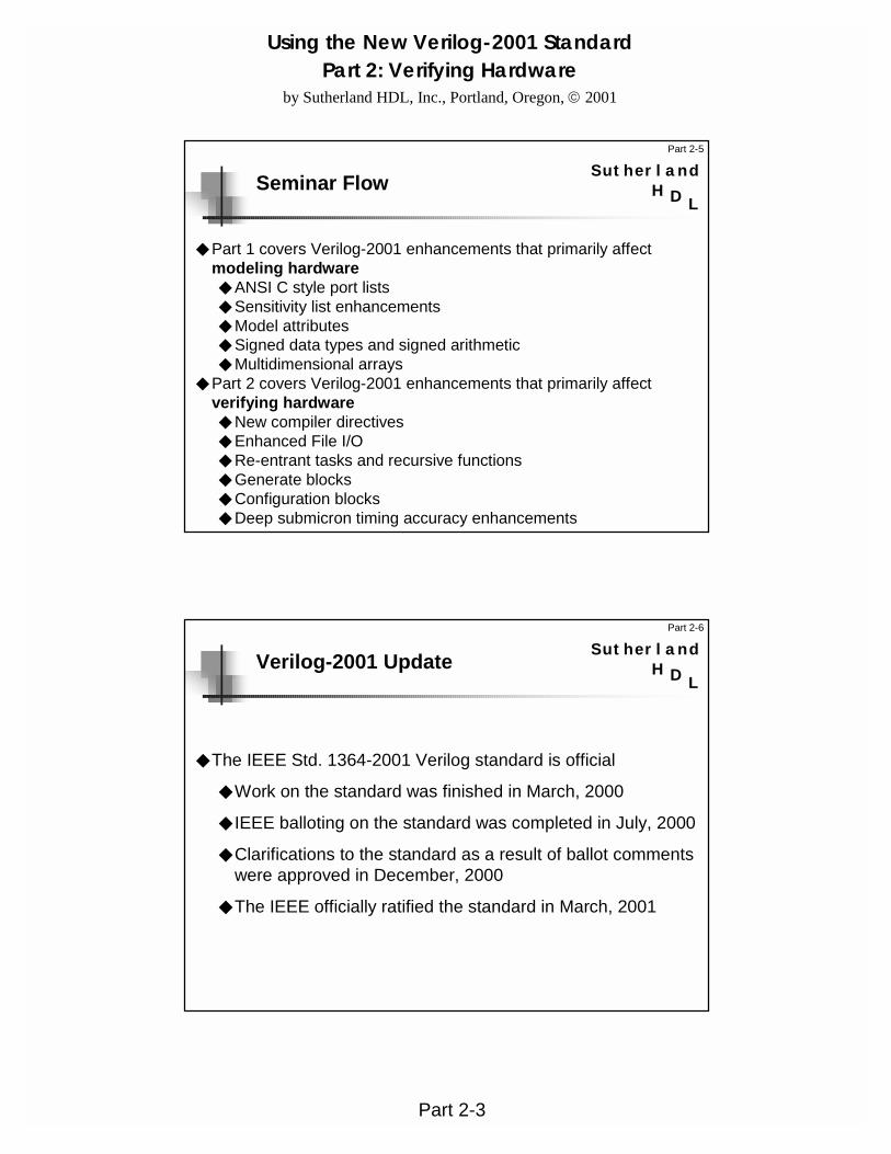
SutherlandSeminar Flow
◆ Part 1 covers Verilog-2001 enhancements that primarily affect modeling hardware◆ ANSI C style port lists◆ Sensitivity list enhancements◆ Model attributes◆ Signed data types and signed arithmetic◆ Multidimensional arrays
◆ Part 2 covers Verilog-2001 enhancements that primarily affect verifying hardware◆ New compiler directives◆ Enhanced File I/O◆ Re-entrant tasks and recursive functions◆ Generate blocks◆ Configuration blocks◆ Deep submicron timing accuracy enhancements
Part 2-6
LH D
SutherlandVerilog-2001 Update
◆ The IEEE Std. 1364-2001 Verilog standard is official
◆ Work on the standard was finished in March, 2000
◆ IEEE balloting on the standard was completed in July, 2000
◆ Clarifications to the standard as a result of ballot comments were approved in December, 2000
◆ The IEEE officially ratified the standard in March, 2001

Using the New Verilog-2001 StandardPart 2: Verifying Hardware
by Sutherland HDL, Inc., Portland, Oregon, 2001
Part 2-4
Part 2-7
LH D
SutherlandWhy a New Standard?
◆ Add enhancements to Verilog◆ Design methodologies are evolving
◆ System level design, intellectual property models, design re-use, very deep submicron, etc.
◆ Cliff Cummings’ “Top Five Enhancement Requests” from a survey at the HDLCon 1996 conference
◆ Clarify ambiguities in Verilog 1364-1995◆ The 1364-1995 reference manual came the Gateway
Design Automation Verilog-XL User’s Manual◆ Verilog-2001 more clearly defines Verilog syntax and
semantics
Part 2-8
LH D
SutherlandGoals for Verilog-2001
◆ Enhance Verilog for◆ Higher level, abstract system level modeling◆ Intellectual Property (IP) modeling◆ Greater timing accuracy for very deep submicron
◆ Make Verilog even easier to use◆ Eliminate redundancies in declarations◆ Simplify syntax of some verbose constructs
◆ Correct errata and ambiguities
◆ Maintain backward compatibility
◆ Ensure that EDA vendors will implement all enhancements!

Using the New Verilog-2001 StandardPart 2: Verifying Hardware
by Sutherland HDL, Inc., Portland, Oregon, 2001
Part 2-5
Part 2-9
LH D
SutherlandOverview of HDL Enhancements
◆ 30+ major enhancements were added to the Verilog HDL◆ Brief description and examples◆ New reserved words
◆ Errata and clarifications◆ Dozens of corrections were made to the 1364-1995
standard◆ Do not affect Verilog users◆ Very important to Verilog tool implementors◆ Not listed in this paper — refer to the 1364-2001 Verilog
Language Reference Manual (LRM)
Part 2-10
LH D
SutherlandSupport For Verilog-2001
◆ Several simulator and synthesis companies are working on adding support for the Verilog-2001 enhancements
◆ Simulators:◆ Model Technology ModelSim — currently supports most new features◆ Co-Design SystemSim — currently supports most new features◆ Synopsys VCS — planned Q3-2001 support for several new features◆ Cadence NC-Verilog and Verilog-XL — no announced release date
◆ Synthesis:◆ Synopsys Presto (replaces DC compiler) — currently supports a
synthesizable subset of Verilog-2001 enhancements◆ Cadence BuildGates — no announced release date◆ Exemplar Leonardo Spectrum — no announced release date
Information last updated July, 2001

Using the New Verilog-2001 StandardPart 2: Verifying Hardware
by Sutherland HDL, Inc., Portland, Oregon, 2001
Part 2-6
Part 2-11
LH D
Sutherland
initialbegina = 0;b = 1;ci = 0;...
stimulus
initialbegin$monitor(sum,co);
end
verificationmodule addbit (a,b,ci,sum,co);input a, b, ci;output sum, co;
endmodule
behavioral or RTLor structural model
design models
Quick Review:Modeling a Test Bench
◆ The Verilog HDL is used to model a simulation test bench◆ The test bench is a module, which contains:
◆ An instance of the top level of the design◆ Procedures to describe the input stimulus◆ Procedures to describe output verification
Part 2-12
LH D
SutherlandQuick Review:Verilog HDL Simulation Commands
◆ The Verilog HDL includes compiler directives and system tasksto control the simulation of Verilog models
◆ `<directive> compiler directives◆ Executed prior to simulation time zero◆ Instructions to simulators on how to compile models◆ Always start with a ` accent grave (the “back tic”)
◆ $<task> system tasks◆ Executed during simulation (i.e.: to display values)◆ Used as programming statements◆ Always start with a $ dollar sign
This chapter only lists some of these simulator commands; Othersare presented later in the course

Using the New Verilog-2001 StandardPart 2: Verifying Hardware
by Sutherland HDL, Inc., Portland, Oregon, 2001
Part 2-7
Part 2-13
LH D
SutherlandVerilog-2001 AddsEnhanced Conditional Compilation
◆ Verilog-1995 provides compiler directives that allow Verilog source to be conditional compiled or excluded
◆ Verilog-2001 adds new directives `ifndef and `elsif for more extensive conditional compilation control...`ifdef RTL_TEST
alu_rtl u1 (...);`elsif GATE
alu_gate u1 (...);`else
initial $display(“ERROR: neither RTL or GATE model instantiated”);`endif
`ifdef <macro_name><verilog_source_code>
`else<verilog_source_code>
`endif
Part 2-14
LH D
SutherlandVerilog-2001 AddsFile and Line Compiler Directives
◆ Verilog-2001 adds file and line compiler directives◆ New directives: `file and `line◆ Document the original location of Verilog source code
◆ Verilog tools often include file name and line number information in error and warning messages
◆ If a pre-process utility program modifies the Verilog source code, the original file and line information could be lost if not preserved by the `file and `line directives

Using the New Verilog-2001 StandardPart 2: Verifying Hardware
by Sutherland HDL, Inc., Portland, Oregon, 2001
Part 2-8
Part 2-15
LH D
SutherlandQuick Review:Text Output System Tasks
◆ $display — displays a formatted message when executed
◆ $strobe — similar to $display, but postpones execution until the end of the current simulation time step
◆ $write — similar to $display, but does not add a new line
◆ $monitor — displays a formatted message when a signal changes value (a background task that is only invoked once!)
always @(posedge clock)$display(“At %d: a=%b b=%b sum=%b”, $time, a, b, sum);
initial$monitor(“At %d: a=%b b=%b sum=%b”, $time, a, b, sum);
Part 2-16
LH D
Sutherland
integer f1;
initialbegin
f1 = $fopen(“my_chip_outputs”);$fmonitor(f1, “time=%t out_bus=%h”, $realtime, out_bus);
end
Note: In Verilog-1995, a file is always opened as a new file
Quick Review:Opening and Writing to Files
◆ $fopen opens a disk file for writing◆ Returns an integer that points to the open file◆ $fmonitor, $fdisplay, $fstrobe and $fwrite print to files◆ Up to 30 other files may be opened◆ $fclose will close a file and free the file pointer

Using the New Verilog-2001 StandardPart 2: Verifying Hardware
by Sutherland HDL, Inc., Portland, Oregon, 2001
Part 2-9
Part 2-17
LH D
Sutherland
integer f1, f2;initialbeginf1 = $fopen(“output.dat”);f2 = $fopen(“errors.dat”);
//check for errors on output//write error messages to all files and standard outforever @(out_bus)if (^out_bus === 1’bx) //xor all bits of bus to compare$fstrobe(f1|f2|1,“OUT_BUS ERROR AT %t”, %realtime);
end
Quick Review:Writing to Multiple Files
◆ $fopen returns a 32-bit “multi-channel descriptor” (mcd)◆ Each mcd has a single bit set◆ Bit zero is reserved
◆ Represents standard out and the simulation log file◆ Multiple files may be written to by OR-ing mcd’s together
Verilog-2001 also reserves bit 31
Part 2-18
LH D
SutherlandQuick Review:Reading Files
◆ Design Verification often needs to read from files, for example◆ To load patterns into RAM and ROM models◆ To read test vector files for stimulus
◆ Verilog has commands to read pattern files into memories◆ $readmemb reads ASCII files with binary patterns◆ $readmemh reads ASCII files with hexadecimal patterns
◆ To read any other file type requires customizing Verilog simulators using the Programming Language Interface (PLI)◆ Part of the IEEE Verilog standard◆ Provides access to the C file I/O routines◆ Very powerful, but requires writing file readers in C

Using the New Verilog-2001 StandardPart 2: Verifying Hardware
by Sutherland HDL, Inc., Portland, Oregon, 2001
Part 2-10
Part 2-19
LH D
SutherlandVerilog-2001 AddsEnhanced File I/O System Tasks
◆ Verilog-2001 adds the ability to open up to 230 files◆ Uses a “file descriptor” (fd) that represents a single file
◆ Sets bit 31 and 1 or more additional bits◆ Cannot be OR-ed to represent multiple files
◆ Adds an optional type argument to $fopen to indicate if the file is opened for reading, writing, update (read/write), append, etc.
◆ Verilog-2001 adds several system task that can both read from and write to fd files, in ASCII or binary◆ $ferror, $fgetc, $fgets, $fflush, $fread, $fscanf, $fseek,
$fsscanf, $ftel, $rewind, $sformat, $swrite, $swriteb,$swriteh, $swriteo, $ungetc
mcd = $fopen{“file_name”); //opens an mcd file for writing, only
fd = $fopen{“file_name”, <type>); //opens fd file for reading/writing
Part 2-20
LH D
Sutherland
example invocation: verilog test.v chip.v +test2
initialbeginif ($test$plusargs(“test1”))$readmemh(“test1.dat”, vectors);
else if ($test$plusargs(“test2”))$readmemh(“test2.dat”, vectors);
else if ($test$plusargs(“test3”))$readmemh(“test3.dat”, vectors);
else$display(“Error: no test option specified”);
end
Quick Review:User Defined Invocation Options
◆ Verilog allows users to create new simulation invocation options◆ The $test$plusargs system function checks to see if a
“plus” option was used when simulation was invoked

Using the New Verilog-2001 StandardPart 2: Verifying Hardware
by Sutherland HDL, Inc., Portland, Oregon, 2001
Part 2-11
Part 2-21
LH D
SutherlandVerilog-2001 AddsEnhanced Invocation Option Tests
◆ Verilog-2001 adds the ability to read arguments of invocation options, as well as doing a true/false test◆ Returns true if option exists, and retrieves the value of any text
after the option tested up to a white space, in the format specified
example invocation: verilog test.v chip.v +testfile=test2.dat
reg [1023:0] file_string;
initialif ($value$plusargs(“testfile=%s”, file_string))$readmemh(file_string, vectors);
else$display(“Error: no test file option specified”);
%b read as binary value%o read as octal value%d read as decimal value %h read as hex value
%e read as real value, exponential format%f read as real value, decimal format%g read as real value, shortest format%s read as character string
$value$plusargs(“option%<format>”, <variable>);
Part 2-22
LH D
Sutherland
parameter seed = 1;initial
for (i=0; i<=`num_tests; i=i+1)@(posedge test_clk)
vector = $random(seed);
• Specifying a seed is optional• Given the same seed value, the same random sequence
will be generated each simulation
Quick Review:Generating Random Values
◆ The $random system function returns a random value◆ Returns a 32-bit signed integer value
In Verilog-1995, the random number generator was not standardized, making it impossible to compare results from two different simulators
Using the New Verilog-2001 StandardPart 2: Verifying Hardware
by Sutherland HDL, Inc., Portland, Oregon, 2001
Part 2-12
Part 2-23
LH D
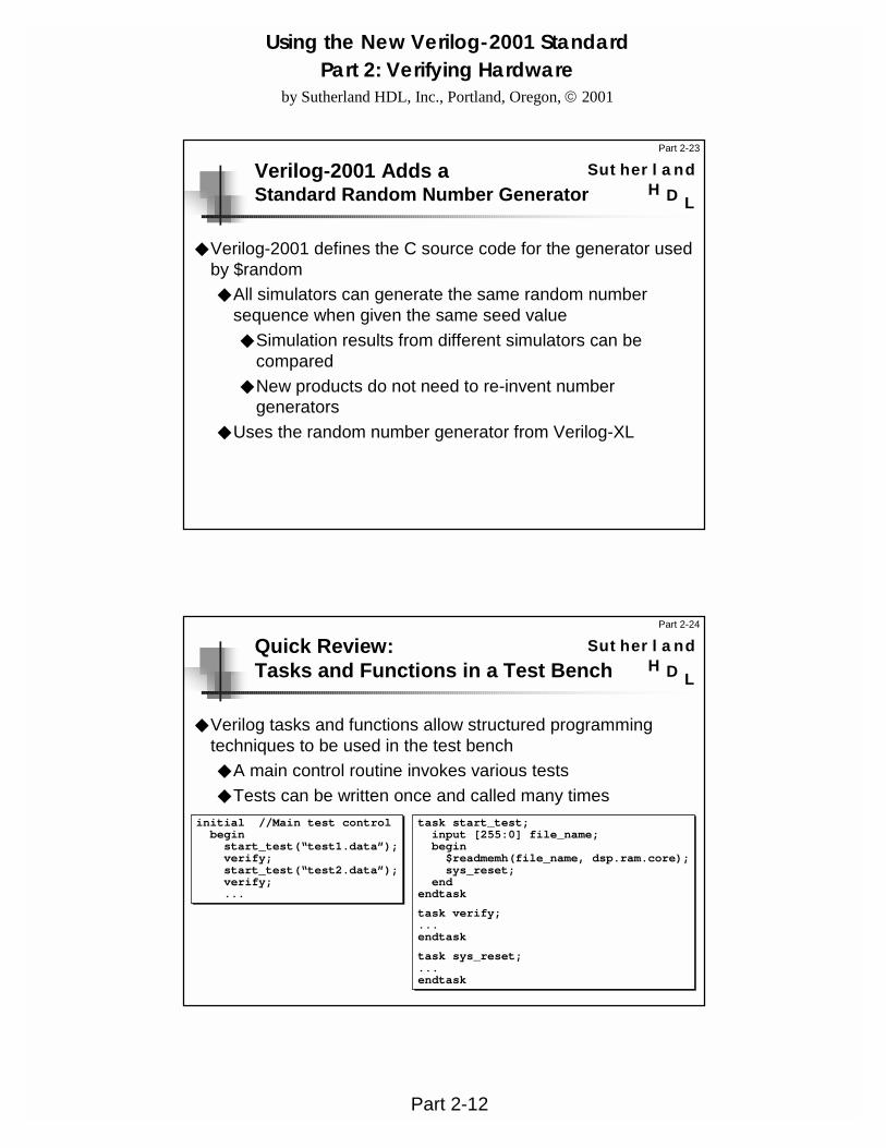
SutherlandVerilog-2001 Adds aStandard Random Number Generator
◆ Verilog-2001 defines the C source code for the generator used by $random◆ All simulators can generate the same random number
sequence when given the same seed value◆ Simulation results from different simulators can be
compared◆ New products do not need to re-invent number
generators◆ Uses the random number generator from Verilog-XL
Part 2-24
LH D
Sutherland
task start_test;input [255:0] file_name;begin$readmemh(file_name, dsp.ram.core);sys_reset;
endendtask
task verify;...endtask
task sys_reset;...endtask
initial //Main test controlbeginstart_test(“test1.data”);verify;start_test(“test2.data”);verify;...
Quick Review:Tasks and Functions in a Test Bench
◆ Verilog tasks and functions allow structured programming techniques to be used in the test bench◆ A main control routine invokes various tests◆ Tests can be written once and called many times

Using the New Verilog-2001 StandardPart 2: Verifying Hardware
by Sutherland HDL, Inc., Portland, Oregon, 2001
Part 2-13
Part 2-25
LH D
SutherlandQuick Review:Verilog Tasks
◆ A task is a special type of procedure◆ Defined in the module in which it is used◆ Called from another procedure, like a subroutine◆ May delay the execution of
statements◆ May have any number of
outputs, inputs, and inouts
module my_chip (...);...always @(posedge clock)beginSendData(data, dout);...
end
task SendData;input [31:0] data_bus;output [31:0] data_out;begin#3.2 data_out = data_bus;
endendtaskendmodule
Arguments are passed in and outof the task in the order of declarationwithin the the task
A task can take time to execute
Part 2-26
LH D
SutherlandQuick Review:Verilog Functions
◆ A function is a special type of procedure◆ Defined in the module in which it is used◆ Called from any place a value can be used◆ Returns a scalar, vector or real-number value◆ Must execute in zero time◆ May only have inputs◆ Must have at least one input
module my_chip (...);...always @(posedge clock)beginresult = Adder(a, b);...
end
function [31:0] Adder;input [31:0] in1, in2;beginAdder = in1 + in2;
endendfunctionendmodule
Arguments are passed in to thefunction in the order of declarationwithin the the function
The value assigned to the function nameis the return value of the function

Using the New Verilog-2001 StandardPart 2: Verifying Hardware
by Sutherland HDL, Inc., Portland, Oregon, 2001
Part 2-14
Part 2-27
LH D
SutherlandVerilog-2001 Adds ANSI C Style Task/Function Declarations
◆ Using the declaration order to pass values is confusing◆ Different syntax than module declarations◆ Different syntax than C
◆ Verilog-2001 allows tasks and functions to define an argument list◆ Documents the order that
values will be passed◆ More consistent with
module declarations andANSI C
module my_chip (...);...always @(posedge clock)beginSendData(data, dout);...
end
task SendData (input [31:0] data_bus,output [31:0] data_out);
begin#3.2 data_out = data_bus;
endendtaskendmodule
Arguments are passed in and out of thetask in the order of the argument list
Part 2-28
LH D
SutherlandVerilog-2001 AddsSigned Functions
◆ With Verilog-1995, functions could return:◆ A 1-bit value
◆ An unsigned vector of any vector width
◆ A signed 32-bit integer ( function integer f3; )
◆ A double-precision real value ( function real f4; )
◆ Verilog-2001 adds the ability to have a signed return of any vector size function signed [63:0] f5 (input [63:0] a, b);
function f1 (input [63:0] a, b);
function [7:0] f2 (input [63:0] a, b);
function integer f3 (input [63:0] a, b);
function real f4 (input [63:0] a, b);
“signed” was a reserved word in the Verilog-1995 standard, but was not used
Using the New Verilog-2001 StandardPart 2: Verifying Hardware
by Sutherland HDL, Inc., Portland, Oregon, 2001
Part 2-15
Part 2-29
LH D
SutherlandVerilog-2001 AddsConstant Functions
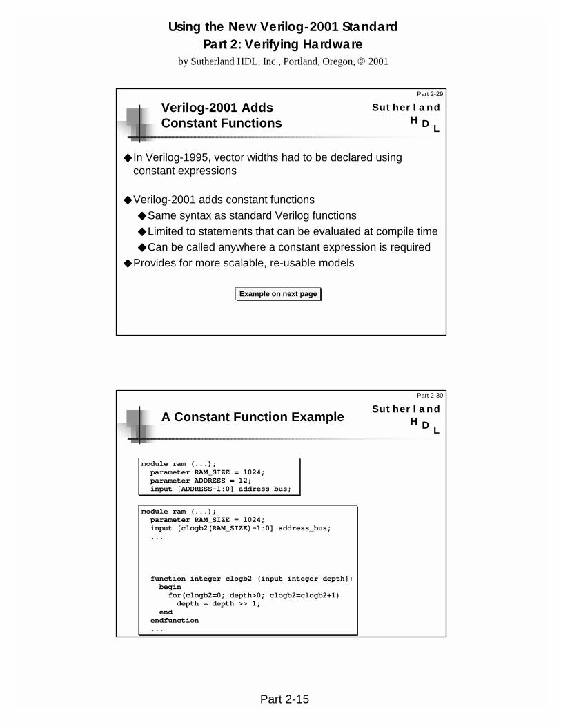
◆ In Verilog-1995, vector widths had to be declared using constant expressions
◆ Verilog-2001 adds constant functions◆ Same syntax as standard Verilog functions◆ Limited to statements that can be evaluated at compile time◆ Can be called anywhere a constant expression is required
◆ Provides for more scalable, re-usable models
Example on next page
Part 2-30
LH D
SutherlandA Constant Function Example
module ram (...);parameter RAM_SIZE = 1024;parameter ADDRESS = 12;input [ADDRESS-1:0] address_bus;
module ram (...);parameter RAM_SIZE = 1024;input [clogb2(RAM_SIZE)-1:0] address_bus;...
function integer clogb2 (input integer depth};beginfor(clogb2=0; depth>0; clogb2=clogb2+1)depth = depth >> 1;
endendfunction...
Using the New Verilog-2001 StandardPart 2: Verifying Hardware
by Sutherland HDL, Inc., Portland, Oregon, 2001
Part 2-16
Part 2-31
LH D
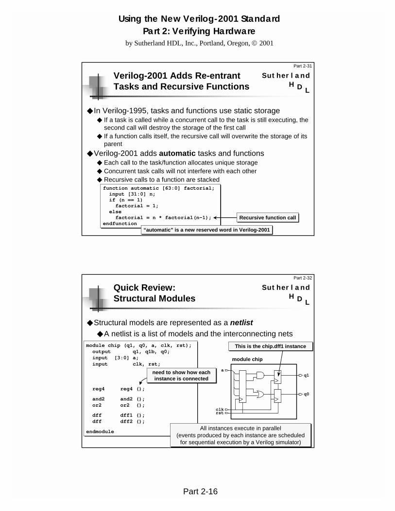
SutherlandVerilog-2001 Adds Re-entrantTasks and Recursive Functions
◆ In Verilog-1995, tasks and functions use static storage◆ If a task is called while a concurrent call to the task is still executing, the
second call will destroy the storage of the first call◆ If a function calls itself, the recursive call will overwrite the storage of its
parent◆ Verilog-2001 adds automatic tasks and functions
◆ Each call to the task/function allocates unique storage◆ Concurrent task calls will not interfere with each other◆ Recursive calls to a function are stackedfunction automatic [63:0] factorial;input [31:0] n;if (n == 1)factorial = 1;
elsefactorial = n * factorial(n-1);
endfunctionRecursive function call
“automatic” is a new reserved word in Verilog-2001
Part 2-32
LH D
SutherlandQuick Review:Structural Modules
◆ Structural models are represented as a netlist◆ A netlist is a list of models and the interconnecting nets
module chip (q1, q0, a, clk, rst);output q1, q1b, q0;input [3:0] a;input clk, rst;
reg4 reg4 ();
and2 and2 ();or2 or2 ();
dff dff1 ();dff dff2 ();
endmodule
need to show how each instance is connected
All instances execute in parallel(events produced by each instance are scheduled
for sequential execution by a Verilog simulator)
rst
q1
clk
a
q0
module chip
This is the chip.dff1 instance

Using the New Verilog-2001 StandardPart 2: Verifying Hardware
by Sutherland HDL, Inc., Portland, Oregon, 2001
Part 2-17
Part 2-33
LH D
Sutherland
`timescale 1ns / 100psmodule dff (q,qb,ck,d,rst,pre);output q, qb;input clk, d, rst, pre;...nand #2.15 p1 (q, n1, n2, rst);...
endmodule
`timescale 1ns / 1nsmodule register (r,d,ld,clr);output [31:0] r;input [31:0] d;input ld, clr;...pullup (nc);dff d0 (r[0], ,ld,d[0],clr,nc);dff d1 (r[1], ,ld,d[1],clr,nc);...
no delays on the module instance
delays can only be specifiedon a primitive instance
Quick Review:Delays and Module Instances
◆ A module instance cannot be specified with delays◆ Delays are specified inside component modules, not on the
instance
Part 2-34
LH D
Sutherland
module RAM (data, address, ...);parameter WORD = 8; //default word widthparameter ADDR = 10; //default address widthparameter SIZE = 1024; //default RAM sizeinout [WORD-1:0] data;input [ADDR-1:0] address;reg [WORD-1:0] core [0:SIZE-1];...
Quick Review:Module Parameters
◆ Parameters are run-time constants◆ Parameters can store:
◆ integer numbers◆ real numbers◆ ASCII text strings◆ min:typ:max delay expressions
Using the New Verilog-2001 StandardPart 2: Verifying Hardware
by Sutherland HDL, Inc., Portland, Oregon, 2001
Part 2-18
Part 2-35
LH D
Sutherland
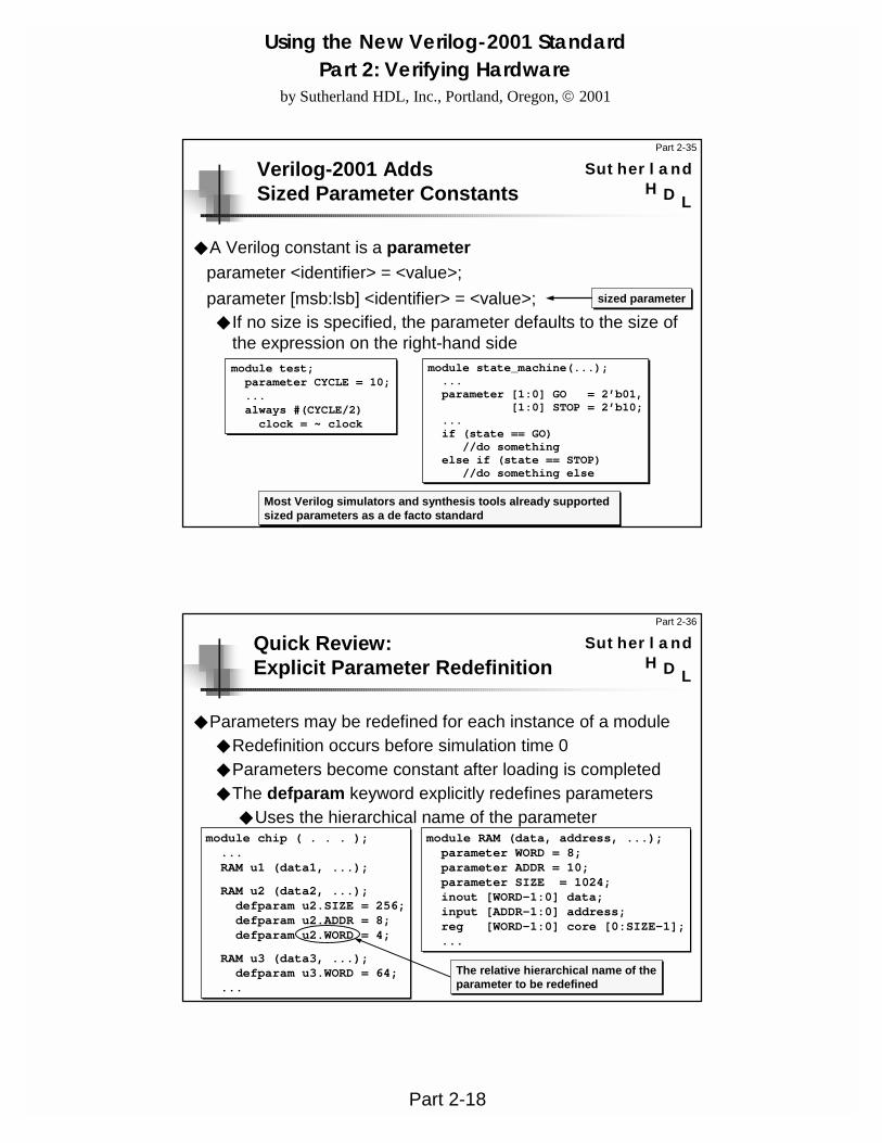
module test;parameter CYCLE = 10;...always #(CYCLE/2)clock = ~ clock
module state_machine(...);...parameter [1:0] GO = 2’b01,
[1:0] STOP = 2’b10;...if (state == GO)
//do somethingelse if (state == STOP)
//do something else
Verilog-2001 AddsSized Parameter Constants
◆ A Verilog constant is a parameter
◆ If no size is specified, the parameter defaults to the size of the expression on the right-hand side
parameter <identifier> = <value>;parameter [msb:lsb] <identifier> = <value>; sized parameter
Most Verilog simulators and synthesis tools already supported sized parameters as a de facto standard
Part 2-36
LH D
Sutherland
module chip ( . . . );...RAM u1 (data1, ...);
RAM u2 (data2, ...);defparam u2.SIZE = 256;defparam u2.ADDR = 8;defparam u2.WORD = 4;
RAM u3 (data3, ...);defparam u3.WORD = 64;
...
module RAM (data, address, ...);parameter WORD = 8;parameter ADDR = 10;parameter SIZE = 1024;inout [WORD-1:0] data;input [ADDR-1:0] address;reg [WORD-1:0] core [0:SIZE-1];...
Quick Review:Explicit Parameter Redefinition
◆ Parameters may be redefined for each instance of a module◆ Redefinition occurs before simulation time 0◆ Parameters become constant after loading is completed◆ The defparam keyword explicitly redefines parameters
◆ Uses the hierarchical name of the parameter
The relative hierarchical name of theparameter to be redefined

Using the New Verilog-2001 StandardPart 2: Verifying Hardware
by Sutherland HDL, Inc., Portland, Oregon, 2001
Part 2-19
Part 2-37
LH D
SutherlandQuick Review:Implicit In-line Parameter Redefinition
◆ Module instantiation and parameter redefinition can be combined into a single statement◆ The # token may be used as part of the module
instantiation to implicitly redefine the module parameters◆ Parameters must be redefined in the same order in which
the parameters are declaredmodule chip ( . . . );
...RAM u1 (data1, ...);
RAM u2 #(4,8,256) (...);
RAM u3 #(64) (...);...
module RAM (data, address, ...);parameter WORD = 8;parameter ADDR = 10;parameter SIZE = 1024;inout [WORD-1:0] data;input [ADDR-1:0] address;reg [WORD-1:0] core [0:SIZE-1];...
parameter values must be passed in the order defined; a parameter cannot be skipped
Part 2-38
LH D
SutherlandVerilog-2001 AddsExplicit In-line Parameter Passing
◆ Verilog-2001 adds the ability to explicitly name parameters when passing parameter values◆ Provides better self-documenting code◆ Parameter values can be passed in any order
module my_chip (...);...RAM #(8,1023) ram2 (...);
endmodule
Verilog-1995module my_chip (...);...RAM #(.SIZE(1023)) ram2 (...);
endmodule
Verilog-2001
module ram (...);parameter WIDTH = 8;parameter SIZE = 256;...
endmodule
Using the New Verilog-2001 StandardPart 2: Verifying Hardware
by Sutherland HDL, Inc., Portland, Oregon, 2001
Part 2-20
Part 2-39
LH D
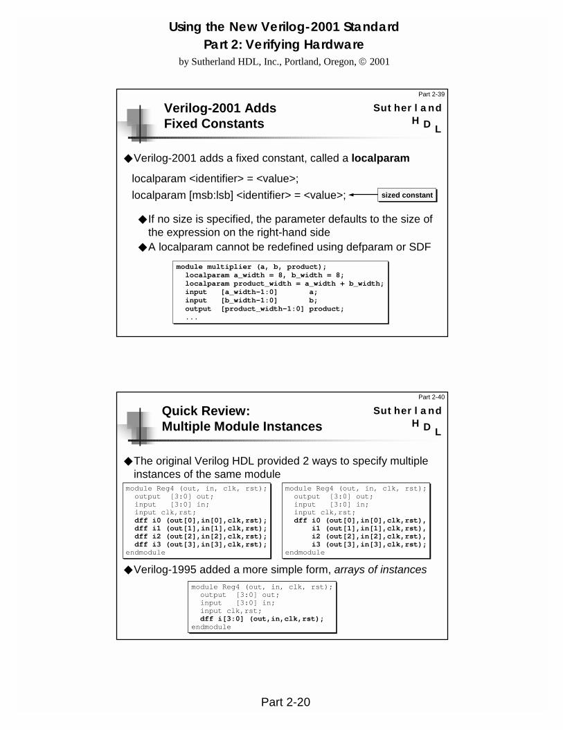
SutherlandVerilog-2001 AddsFixed Constants
◆ Verilog-2001 adds a fixed constant, called a localparam
◆ If no size is specified, the parameter defaults to the size of the expression on the right-hand side
◆ A localparam cannot be redefined using defparam or SDF
localparam <identifier> = <value>;localparam [msb:lsb] <identifier> = <value>; sized constant
module multiplier (a, b, product);localparam a_width = 8, b_width = 8;localparam product_width = a_width + b_width;input [a_width-1:0] a;input [b_width-1:0] b;output [product_width-1:0] product;...
Part 2-40
LH D
SutherlandQuick Review:Multiple Module Instances
◆ The original Verilog HDL provided 2 ways to specify multiple instances of the same module
◆ Verilog-1995 added a more simple form, arrays of instances
module Reg4 (out, in, clk, rst);output [3:0] out;input [3:0] in;input clk,rst;dff i0 (out[0],in[0],clk,rst);dff i1 (out[1],in[1],clk,rst);dff i2 (out[2],in[2],clk,rst);dff i3 (out[3],in[3],clk,rst);
endmodule
module Reg4 (out, in, clk, rst);output [3:0] out;input [3:0] in;input clk,rst;dff i0 (out[0],in[0],clk,rst),
i1 (out[1],in[1],clk,rst),i2 (out[2],in[2],clk,rst),i3 (out[3],in[3],clk,rst);
endmodule
module Reg4 (out, in, clk, rst);output [3:0] out;input [3:0] in;input clk,rst;dff i[3:0] (out,in,clk,rst);
endmodule
Using the New Verilog-2001 StandardPart 2: Verifying Hardware
by Sutherland HDL, Inc., Portland, Oregon, 2001
Part 2-21
Part 2-41
LH D
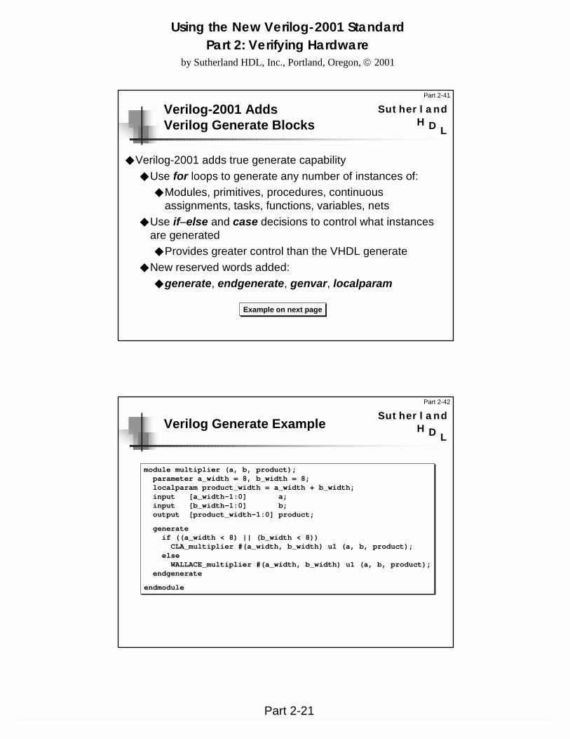
SutherlandVerilog-2001 AddsVerilog Generate Blocks
◆ Verilog-2001 adds true generate capability◆ Use for loops to generate any number of instances of:
◆ Modules, primitives, procedures, continuous assignments, tasks, functions, variables, nets
◆ Use if–else and case decisions to control what instances are generated◆ Provides greater control than the VHDL generate
◆ New reserved words added:◆ generate, endgenerate, genvar, localparam
Example on next page
Part 2-42
LH D
SutherlandVerilog Generate Example
module multiplier (a, b, product);parameter a_width = 8, b_width = 8;localparam product_width = a_width + b_width;input [a_width-1:0] a;input [b_width-1:0] b;output [product_width-1:0] product;
generateif ((a_width < 8) || (b_width < 8))CLA_multiplier #(a_width, b_width) u1 (a, b, product);
elseWALLACE_multiplier #(a_width, b_width) u1 (a, b, product);
endgenerate
endmodule
Using the New Verilog-2001 StandardPart 2: Verifying Hardware
by Sutherland HDL, Inc., Portland, Oregon, 2001
Part 2-22
Part 2-43
LH D
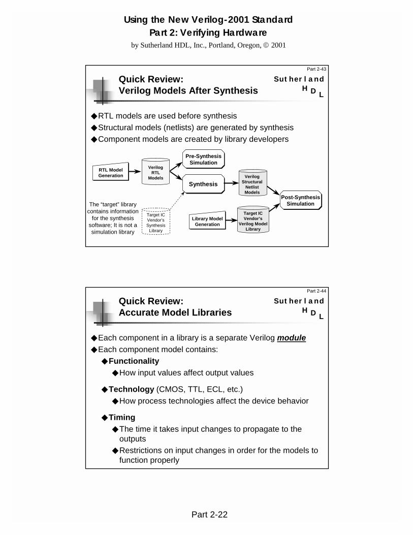
SutherlandQuick Review:Verilog Models After Synthesis
◆ RTL models are used before synthesis◆ Structural models (netlists) are generated by synthesis ◆ Component models are created by library developers
Target ICVendor’s
Verilog ModelLibrary
Library ModelGeneration
VerilogRTL
Models
Pre-SynthesisSimulation
RTL ModelGeneration
Synthesis
Target ICVendor’sSynthesis
Library
The “target” library contains information
for the synthesis software; It is not a simulation library
VerilogStructural
NetlistModels
Post-SynthesisSimulation
Part 2-44
LH D
SutherlandQuick Review:Accurate Model Libraries
◆ Each component in a library is a separate Verilog module◆ Each component model contains:
◆ Functionality◆ How input values affect output values
◆ Technology (CMOS, TTL, ECL, etc.)◆ How process technologies affect the device behavior
◆ Timing◆ The time it takes input changes to propagate to the
outputs ◆ Restrictions on input changes in order for the models to
function properly

Using the New Verilog-2001 StandardPart 2: Verifying Hardware
by Sutherland HDL, Inc., Portland, Oregon, 2001
Part 2-23
Part 2-45
LH D
Sutherland
specify(in *> out) = 3;$setup(in, posedge clk, 1.2);specparam drive = 0.4; specparam load = 1.8;
endspecify
Quick Review:Specify Blocks
◆ Specify blocks specify timing information about a module◆ Must be inside the module boundary◆ May be defined anywhere within the module
◆ Specify blocks contain:◆ Pin-to-pin path delays for propagation times from module
inputs to module outputs◆ Timing constraint checks such as setup and hold times◆ specparam constants to store data about the model
Part 2-46
LH D
SutherlandVerilog-2001 AddsOn-detect Pulse Error Propagation
◆ Verilog-1995 has on-event pulse error propagation◆ A pulse is a glitch on the inputs of a module path that is less
than the delay of the path◆ An input pulse propagates to a path output as an X, with the
same delay as if a valid input change had propagated to the output
◆ Verilog-2001 adds on-detect pulse error propagation◆ As soon as an input pulse is detected, a logic X is
propagated to a path output, without the path delay◆ New reserved words added:
◆ pulsestyle_onevent, pulsestyle_ondetect

Using the New Verilog-2001 StandardPart 2: Verifying Hardware
by Sutherland HDL, Inc., Portland, Oregon, 2001
Part 2-24
Part 2-47
LH D
SutherlandVerilog-2001 AddsNegative Pulse Detection
◆ Due to different rising-transition and falling-transition delays, it is possible for the trailing edge of a glitch to propagate before the leading edge has propagated
◆ In Verilog-1995, a negative pulse is cancelled◆ Verilog-2001 adds negative pulse detections
◆ Negative pulse detection will propagate a logic X for the duration of the negative pulse
◆ New reserved words added:◆ showcancelled, noshowcancelled
Part 2-48
LH D
SutherlandQuick Review:Input Timing Constraints
◆ Input timing constraints can be monitored using system tasks
◆ Reference event is the input that establishes a reference point for changes on the data event
◆ Data event is the input that is monitored for changes◆ Limit is the timing required between reference and data◆ Notifier (optional) is a scalar reg that is toggled on violations
$setup (data_event, reference_event, setup_limit, notifier);$hold (reference_event, data_event, hold_limit, notifier);$setuphold (reference_event, data_event, setup_limit, hold_limit, notifier);$skew (reference_event, data_event, skew_limit, notifier);$recovery (reference_event, data_event, recovery_limit, notifier);$period (reference_event, data_event, period_limit, notifier);$width (reference_event, width_limit, max_threshold, notifier);
Using the New Verilog-2001 StandardPart 2: Verifying Hardware
by Sutherland HDL, Inc., Portland, Oregon, 2001
Part 2-25
Part 2-49
LH D
SutherlandVerilog-2001 AddsNew Timing Constraint Checks
◆ Verilog-2001 adds new timing constraint checks to more accurately model very deep submicron input constraints:◆ $removal◆ $recrem◆ $timeskew◆ $fullskew
◆ Refer to the IEEE 1364-2001 Verilog standard for details on these tasks
Part 2-50
LH D
SutherlandVerilog-2001 AddsNegative Timing Constraints
◆ Verilog-2001 adds the ability to specify negative values for:◆ $setuphold setup and hold times
◆ Adds new, optional arguments to the Verilog-1995 $setuphold task
◆ $recrem recovery and removal times◆ A new timing check task in Verilog-2001

Using the New Verilog-2001 StandardPart 2: Verifying Hardware
by Sutherland HDL, Inc., Portland, Oregon, 2001
Part 2-26
Part 2-51
LH D
SutherlandVerilog-2001 AddsEnhanced SDF support
◆ Verilog-2001 defines:◆ How timing objects in SDF map to objects in Verilog◆ Based on the latest SDF standard, IEEE 1497-1999
◆ Verilog-2001 adds a standard $sdf_annotate system task◆ Already a de-facto standard in all simulators
◆ Verilog-2001 changes the syntax of the specparam constant◆ Can now be declared at the module level as well as within a
specify block (this change was required to support SDF labels)
Part 2-52
LH D
SutherlandQuick Review:Managing Verilog Designs
◆ Designs are often made up of many modules◆ Typically, each module is in a separate file x a complete
design might be made up of hundreds of files◆ In a top-down design flow, there will be RTL versions and
synthesized gate-level versions of the same module◆ Verilog-1995 and earlier generations of Verilog left design
management up to software tools—managing the location and version of Verilog models was not part of the Verilog language
◆ Most Verilog simulators provide:◆ A -f invocation option to manage design files◆ -v and - y invocation options to manage design libraries◆ The `uselib compiler directive to manage model versions

Using the New Verilog-2001 StandardPart 2: Verifying Hardware
by Sutherland HDL, Inc., Portland, Oregon, 2001
Part 2-27
Part 2-53
LH D
SutherlandQuick Review:Using `uselib With Model Libraries
◆ Most Verilog simulators have a `uselib compiler directive to scan libraries◆ `uselib is not in the IEEE Verilog standard (1995 or 2001)◆ The syntax is similar to the -v and -y options
◆ With `uselib, library information can be specified within the Verilog source code instead of at the invocation command◆ Different instances of a module can come from different
librariesmodule system (...);...
`uselib file=../moto_lib.vmoto_asic i1 (...);
`uselib dir=../lsi500k.dir libext=.vlsi_asic i2 (...);
endmodule
Part 2-54
LH D
SutherlandVerilog-2001 AddsConfigurations
◆ Verilog-2001 adds configuration blocks◆ All software tools will have a consistent method◆ The version for each module instance can be specified
◆ Virtual libraries specified within Verilog source code◆ Physical file locations specified in a “map” file
◆ New reserved words added: config, endconfig, design, instance, cell, use, liblist
Configuration rules and an example are on the next 2 pages

Using the New Verilog-2001 StandardPart 2: Verifying Hardware
by Sutherland HDL, Inc., Portland, Oregon, 2001
Part 2-28
Part 2-55
LH D
SutherlandVerilog Configuration Notes
◆ Verilog design hierarchy is modeled the same as always
◆ Configurations specify which module source code should be used for each instance of a module.
◆ With Verilog-1995, it is up to the simulator on how to specify which model version should be used for each instance (if the simulator can do it at all)
◆ The configuration block is specified outside of all modules◆ Can be in the same file as the Verilog source code◆ Can be in a separate file◆ Verilog model source code does not need to be modified in order to change the
design configuration!
◆ A separate file maps logical library names to physical file locations◆ Verilog source code does not need to be modified when a design is moved to a
different physical source location!
Part 2-56
LH D
SutherlandVerilog Configuration Example
module test;...myChip dut (...);...
endmodule
module myChip(...);...adder a1 (...);adder a2 (...);...
endmodule
Verilog Design/* define a name for this configuration */config cfg4
/* specify where to find top level modules */design rtlLib.test
/* set the default search order for findinginstantiated modules */
default liblist rtlLib gateLib;
/* explicitly specify which library to usefor the following module instance */
instance test.dut.a2 liblist gateLib;endconfig
Configuration Block (part of Verilog source code)
/* location of RTL models (current directory) */library rtlLib "./*.v";
/* Location of synthesized models */library gateLib "./synth_out/*.v";
Library Map File
Using the New Verilog-2001 StandardPart 2: Verifying Hardware
by Sutherland HDL, Inc., Portland, Oregon, 2001
Part 2-29
Part 2-57
LH D
SutherlandVerilog-2001 AddsEnhanced PLA Modeling
◆ Verilog-2001 extends the capability of the PLA system tasks($async$or$array, $async$and$array, etc.)
◆ In Verilog-1995, arguments had to be scalar
◆ In Verilog-2001, arguments can be vectors
Part 2-58
LH D
SutherlandVerilog-2001 AddsExtended VCD Files
◆ Verilog-2001 adds new Value Change Dump (VCD) capabilities◆ Dump port change values◆ Dump strength level changes◆ Dump the time at which simulation finishes◆ New system tasks added:
◆ $dumpports, $dumpportsall, $dumpportsoff, $dumpportson, $dumpportslimit and $dumpportsflush

Using the New Verilog-2001 StandardPart 2: Verifying Hardware
by Sutherland HDL, Inc., Portland, Oregon, 2001
Part 2-30
Part 2-59
LH D
SutherlandVerilog-2001 AddsPLI Enhancements
◆ Several enhancements added to the VPI library◆ Simulation control
◆ Stop, finish, save, restart, etc.◆ Support for all the new Verilog-2001 HDL constructs
◆ Multidimensional arrays, attributes, signed arithmetic, recursive functions, enhanced file I/O, etc.
◆ Maintenance updates to TF and ACC libraries◆ Corrected errata◆ Clarified ambiguities
Part 2-60
LH D
SutherlandThe VPI Library Is The Future!
◆ All enhancements to the Verilog languageare only supported in the VPI library of the PLI◆ The TF and ACC libraries (“PLI 1.0”)
are not being maintained,but not enhanced
The TF and ACC libraries are prehistoric!You should be using the VPI PLI library…
Using the New Verilog-2001 StandardPart 2: Verifying Hardware
by Sutherland HDL, Inc., Portland, Oregon, 2001
Part 2-31
Part 2-61
LH D
SutherlandCongratulations!
this concludes Part 2 of the workshop“Using the New Verilog-2001 Standard”
◆ If you are a design engineer, we recommend:“Comprehensive Verilog HDL for Design Engineers”
◆ By Sutherland HDL, Inc. — www.sutherland-hdl.com◆ Our 4-day workshop covers the entire Verilog language,
including the new Verilog-2001 features, with lots of labs◆ If you are a verification engineer, we recommend:
“Advanced Verilog PLI Training”◆ By Sutherland HDL, Inc. — www.sutherland-hdl.com◆ A 4-day workshop on customizing and extending Verilog
simulators by linking in C-based models, test routines, etc.
Where can I learn even more?
Part 2-62
LH D
SutherlandAdditional Resources:Verilog & Synthesis Books
◆ www.verilog-2001.com◆ Information about the Verilog-2001 standard
◆ Verilog HDL Quick Reference Guide, Verilog-2001 version◆ Stuart Sutherland—easy place for keywords, syntax, etc.
◆ IEEE Std 1364-2001◆ IEEE Standard Hardware Description Language Based on
the Verilog Hardware Description Language◆ The Verilog Hardware Description Language
◆ Donald Thomas & Phil Moorby—good Verilog introduction◆ The Verilog PLI Handbook
◆ Stuart Sutherland—using the PLI to extend the Verilog HDLcheck www.sutherland-hdl.com for a list of over 30 books
Using the New Verilog-2001 StandardPart 2: Verifying Hardware
by Sutherland HDL, Inc., Portland, Oregon, 2001
Part 2-32
Part 2-63
LH D
SutherlandAdditional Resources:Verilog & Synthesis Resources
◆ www.sutherland-hdl.com◆ Stuart Sutherland's web site — lots of Verilog web links
◆ comp.lang.verilog newsgroup◆ Great place to get quick answers to Verilog questions◆ Other newsgroups: comp.lang.vhdl, comp.cad.synthesis,
comp.arch.fpga◆ ESNUG - E-mail Synopsys Users Group
◆ John Cooley — [email protected]◆ Verification Guild – Verilog/VHDL verification newsletter
◆ Janick Bergeron's newsletter on design verification —www.janick.bergeron.com
Part 2-64
LH D
SutherlandAdditional Resources:Verilog & Synthesis Conferences
◆ HDLCon — International HDL Conference◆ Formerly IVC/VIUF (International Verilog Conference /
VHDL International Users Forum)◆ Good conference for information about Verilog/VHDL
software tools◆ www.hdlcon.org
◆ SNUG — Synopsys Users Group Conference◆ The best technical conference on Verilog/VHDL design
methodologies and synthesis◆ www.synopsys.com (click on the SNUG button)

![Verilog design example [相容模式] - SOC & DSP Labsocdsp.ee.nchu.edu.tw/class/download/vlsi_dsp_102/night/DSP/Veril… · Verilog HDL Code(part 1): Symbol view: Verilog HDL](https://static.fdocuments.net/doc/165x107/5f8b5fb5089abf43c543d928/verilog-design-example-c-soc-dsp-verilog-hdl-codepart-1i.jpg)