Using Solid State Calorimetry for Measuring Gas …cdn.intechopen.com/pdfs/25069.pdfUsing Solid...
17
12 Using Solid State Calorimetry for Measuring Gas Metal Arc Welding Efficiency Stephan Egerland 1 and Paul Colegrove 2 1 FRONIUS International GmbH, 2 Cranfield University, 1 Austria 2 United Kingdom 1. Introduction The thermal profile of fusion welding or its heat input can cause degradation of the material properties, which is reflected in the microstructural changes, occurring in the heat affected zone (HAZ). Hence, quantifying the amount of thermal energy transferred from the welding arc to the workpiece is beneficial to understanding this phenomenon. High accuracy in determining the thermal weld process efficiency, improves the predictive ability of numerical models. Weld ‘process efficiency’ is also called ‘efficiency’, ‘energy absorption’ or ‘heat transfer efficiency’. (AWS, 2001) defines “energy absorption” by the workpiece, regularly denoted by the Greek symbol (eta), as the fraction of the “total energy supplied by the heat source”, that is, the arc. Depending amongst others on material properties and heat source density, the final energy absorption can vary. According to (Lancaster, 1986) this relationship can be described by: 1 1 e p w q nq mq EI (1) represents the thermal arc efficiency, e q is the rate of heat transfer from the arc to the electrode in cal s -1 , n stands for the energy proportion radiated and convected from the arc column per unit time and transferred to the workpiece, p q is the energy radiated and convected from the arc column per unit time in cal s -1 , m represents the proportion of anode energy radiated away from the workpiece, w q is the arc heat fraction absorbed by the workpiece in cal s -1 . As E and I stand for voltage and current, respectively, representing particularly constant voltage welding processes, for advanced welding power supplies equation (1) can be written in a more general form as: 1 1 e p w a q nq mq q (2) www.intechopen.com
Transcript of Using Solid State Calorimetry for Measuring Gas …cdn.intechopen.com/pdfs/25069.pdfUsing Solid...
12
Using Solid State Calorimetry for Measuring Gas Metal Arc
Welding Efficiency
Stephan Egerland1 and Paul Colegrove2 1FRONIUS International GmbH,
2Cranfield University, 1Austria
2United Kingdom
1. Introduction
The thermal profile of fusion welding or its heat input can cause degradation of the material
properties, which is reflected in the microstructural changes, occurring in the heat affected
zone (HAZ). Hence, quantifying the amount of thermal energy transferred from the welding
arc to the workpiece is beneficial to understanding this phenomenon. High accuracy in
determining the thermal weld process efficiency, improves the predictive ability of
numerical models. Weld ‘process efficiency’ is also called ‘efficiency’, ‘energy absorption’ or
‘heat transfer efficiency’. (AWS, 2001) defines “energy absorption” by the workpiece,
regularly denoted by the Greek symbol (eta), as the fraction of the “total energy supplied
by the heat source”, that is, the arc. Depending amongst others on material properties and
heat source density, the final energy absorption can vary. According to (Lancaster, 1986) this
relationship can be described by:
1
1e p wq n q mq
EI (1)
represents the thermal arc efficiency, eq is the rate of heat transfer from the arc to the
electrode in cal s-1, n stands for the energy proportion radiated and convected from the arc
column per unit time and transferred to the workpiece, pq is the energy radiated and
convected from the arc column per unit time in cal s-1, m represents the proportion of anode
energy radiated away from the workpiece, wq is the arc heat fraction absorbed by the
workpiece in cal s-1. As E and I stand for voltage and current, respectively, representing
particularly constant voltage welding processes, for advanced welding power supplies
equation (1) can be written in a more general form as:
1
1e p w
a
q n q mq
q (2)
www.intechopen.com

Arc Welding
266
here aq is the average instantaneous power from the welding process, being defined as:
0
1T
aq UIdtT
(3)
with T representing the total welding time, and t the time. As eq can be ignored with
consumable electrode processes such as Gas Metal Arc Welding (GMAW) the expression
may be written as (Lancaster, 1986):
1
1p w
a
n q mq
q (4)
The power input to the plate, qi can be found simply by:
i aq q (5)
Of the energy that is transferred to the workpiece, some will be used to melt the material in
the fusion zone, while the remainder heats up the base material. Therefore it is useful to
define the melting efficiency m according to (DuPont & Marder, 1995 and Fuerschbach &
Eisler, 1999 and Eder, 2009) as the energy required to melt the fusion zone area divided by
the energy input to the plate:
hm
i
vA
q
(6)
v represents welding speed, A is fusion zone cross section; ρ is the density and δh is the
melting enthalpy per unit mass which is given by:
m
r
T
h f p
T
h c T dT (7)
where fh is for heat of fusion. pc stands for the specific heat, as T , rT and mT represent
absolute-, room- and melting temperature, respectively. Welding calorimetry is used to measure the process efficiency through determining the
energy transferred to the workpiece, as well, as to question physical aspects of heat and
current flow distribution as studied e.g. by (Tsai and Eagar, 1985 and Lu and Kou, 1988).
The authors used a calorimeter consisting of a split hollow water cooled copper Dee-anode
(split-anode), developed by (Nestor, 1962). Current and voltage in autogenous gas tungsten
arc welding (GTAW) and their affect on energy distribution and process efficiency were
investigated. A study on efficiency of variable polarity plasma arc welding on AA 6061
aluminium alloy specimens was carried out by (Evans et al., 1998). The samples were
“quickly placed into a calorimeter and the retained heat measured after the temperature of
the water in the calorimeter stabilised (about 2 minutes)”. However, no detailed information
is provided concerning the time scatter between welding the sample and immersing it into
the calorimeter. This fact has been taken into greater account by (Bosworth, 1991), using
water calorimetry for ferrous parent material gas metal arc welding. Researching the
www.intechopen.com

Using Solid State Calorimetry for Measuring Gas Metal Arc Welding Efficiency
267
effective heat input applying solid wire electrodes the delay between “cessation of welding
to quenching of the sample was standardised at 15 s for all of the tests”. A “maximum
uncertainty of 5% to the (efficiency) value” was indicated and it was found an increasing
voltage or arc length, respectively, decreased the efficiency. The method, reported by (Kou,
1987), involved GTAW on an aluminium tube (“if the workpiece is a pipe”) which is
continuously cooled with water. The temperature rise throughout welding was measured
using “differential-thermocouples” and plotted over time. The energy input to the plate was
then calculated by (Kou, 1987, 2003):
0 0
i weld p out in p out inq t Wc T T dt Wc T T dt (8)
W is water mass flow rate and cp is the specific heat of water. inT and outT represent the
water inlet- and outlet temperature, as t and weldt are for time and weld time, respectively.
The Seebeck envelope calorimeter method uses a similar principle, however the weld is
sealed in an insulated, water cooled box after welding and a temperature gradient layer is
used to calculate the heat loss to the water. According to (Kou, 2003), knowing the gradient
layer thickness L , its thermal conductivity k and the heat conducting area cA allows to
calculate the heat transfer from the heat source to the calorimeter as:
weld c
0
Ai
Tq t k dt
L
(9)
Seebeck welding calorimetry was particularly applied for studying gas tungsten- and plasma arc welding (Giedt et al. 1989 and Fuerschbach and Knorovsky, 1991). Conducting efficiency investigations on AISI 304 stainless steel coupons in a Seebeck calorimeter (Giedt et al., 1989) found ~ 80% process efficiency, confirmed to be “consistent with results from other calorimeter type measurements”. The main issue with these methods of calculating the heat input to the weld is the time to undertake the experiment; which restricts its suitability for general application. It was shown e.g. by (Giedt et al., 1989) that “up to six hours was required for the workpiece to come to equilibrium with the constant-temperature cooling water.” More rapid process efficiency measurement is possible, applying the liquid nitrogen calorimeter method, as used e.g. by (Joseph et al., 2003 and Pepe et al., 2011). The specimen, welded and immersed immediately into a Dewar filled with liquid nitrogen, vaporises a specific mass of nitrogen, Δmn. Knowing the latent heat of vaporisation for liquid nitrogen cn the energy to cool the welded sample to liquid nitrogen temperature, Es , can be calculated:
s n nE m c (10)
To enable the energy input to the sample to be calculated, two energy losses need to be
considered: the energy loss from normal nitrogen vaporisation, En; and the energy required
to cool the specimen from room temperature to liquid nitrogen temperature, Ea. Therefore
the final expression for calculating the energy input to the specimen is:
i weld s n aq t E E E (11)
www.intechopen.com

Arc Welding
268
A final method for measuring the process efficiency is that reported in (Cantin & Francis, 2005) who used a solid state calorimeter encased in an insulated box. To determine the process efficiency of aluminium gas tungsten arc welding, an appropriate weld specimen was welded within an insulated box. As for the other processes, the energy input to the plate was found by:
0 0
weld w pw b pb( )d ( )de eT T
i
T T
q t m c T T m c T T (12)
Here wm and bm represent the workpiece and backing bar mass, respectively, and pwc as
pbc stand for their specific heat. T , 0T and eT are for temperature, initial temperature and
equilibrium temperature, respectively. The method is similar to the Seebeck method in that
the weld is contained within an insulated box after welding, however rather than waiting
for the weld to cool back to room temperature, the final equilibrium temperature is
calculated. The main advantage of the solid state calorimeter is a significant reduction in the
measurement time. Calorimetric measurements have been done on a variety of processes including Gas Tungsten Arc Welding (Fuerschbach and Knorovsky, 1991 and DuPont and Marder, 1995 and Giedt et al. 1989 and Cantin and Francis, 2005), Gas Metal Arc Welding (DuPont and Marder, 1995 and Joesph et al. 2003 and Pepe, 2010 and Bosworth, 1991), and Plasma Arc Welding (Fuerschbach and Knorovsky, 1991 and DuPont and Marder, 1995). The process efficiency for consumable electrode processes is generally about 10-20% higher than non-consumable processes (DuPont and Marder, 1995). The process efficiency of GMAW which is the subject of this investigation vary. (DuPont and Marder, 1995 and Bosworth, 1991) who used water based calorimeters claimed that the efficiency could be between 80-90%. Joseph et al., 2003 who used a liquid nitrogen calorimeter and longer duration welds (up to 60 seconds) claimed that the value was closer to 70%. Also using a liquid nitrogen calorimeter (Pepe, 2010) found that the process efficiency varied between 78-88% for CMT welding. Although there doesn’t appear to be any difference between CV and pulsed welding (Joseph et al. 2003 and Bosworth, 1991), two articles (Hsu and Soltis, 2002 and Bosworth, 1991) have reported that the efficiency with short circuiting or surface tension transfer modes is significantly higher (up to 95%). The latter (Bosworth, 1991) found that increasing arc voltage and therefore arc length reduced the efficiency, however interestingly (Cantin and Francis, 2005) found no such link with arc length in their investigation of GTAW. Finally, the arc efficiencies are increased when welding in a groove compared with bead on plate welds (Bosworth, 1991). This chapter compares the process efficiency of pulsed GMAW with the Fronius Cold Metal Transfer (CMT) GMAW process. Pulsed GMAW may be classified as ‘free flight’ and, if appropriately adjusted, short circuit free. In comparison, CMT which was invented by (Hackl and Himmelbauer, 2005) is principally a ‘short arc’ process. The major difference to natural short circuit droplet transfer is CMT applies both a reproducible transient control of weld current and voltage, as well as mechanical support to the molten droplet detachment. These features are explained in Fig. 1. The wire electrode is fed forward until short-circuiting with the liquid weld pool. Detected by the weld system, the wire is instantaneously retracted from the weld pool by reversing the feeding direction, and simultaneously decreasing weld current and voltage. The process
www.intechopen.com

Using Solid State Calorimetry for Measuring Gas Metal Arc Welding Efficiency
269
has high process stability and reproducibility, and reduced thermal input to the parent material.
t
t
t
Uw
Iw
wfs
T
Fig. 1 Representative wire-feed speed (wfs), voltage (Uw) and current plots (Iw) vs. time (t) for the CMT process.
2. Experimental
2.1 Welding systems and experiments GMAW-P and CMT were investigated. In order to simplify the experimental setup, a single welding system was chosen, capable of operating both processes. See Fig. 2, for configuration overview.
Fig. 2. Schematic of welding system configuration.
www.intechopen.com

Arc Welding
270
Note that items 1 - 12 in Fig. 2 are as follows: 1. Inverter Welding Power Source (FRONIUS TPS 4000 Type *) 2. Cooling Unit (FRONIUS FK 4000 R Type) 3. Trolley 4. 4-wheel drive wire feeding unit (FRONIUS VR 7000 CMT Type) 5. Wire Buffer hose package (water cooled 4.25 m – equipped with appropriate wire liner) 6. Wire buffer + torch hose package (1.2 m – equipped with appropriate wire liner) 7. Special CMT drive unit welding torch
8. Torch neck (36°/500A – equipped with appropriate wire liner and contact tip 1.0 mm)
9. Remote Control Unit (FRONIUS RCU 5000i Type) 10. Robot Control Cable 11. Robot Control 12. Robot-Power Source Interface (*) CMT Release For high reproducibility reasons, an industrial welding robot type ABB IRB 2400 + IRC 5 robot control and DEVICENET-robot interface was used. Welding current was measured by applying a Hall-effect current sensor (LEM™ shunt). A sense lead, connected to the torch neck (closely to the contact tip area) was used in order to obtain the voltage measurement. Current and voltage acquisition was carried out using a high-speed digital oscilloscope (Tektronix DPO 4034), adjusting a sampling rate of 25 kS s-1. The power input from the welding process was calculated from equation (3). Mild carbon steel S235 J2 (DIN EN 10025) was used for the experiments and Table 1 provides the chemical composition according to this standard. The material was sandblasted prior to welding and two different geometries were used for the welding: 250 x 50 x 5 mm (see Fig. 3 (a, b)) which was used for the bead on plate welds; and 250 x 50 x 12 mm (see Fig. 3 (c)) which was the square groove geometry and was meant to simulate welding in a narrow gap. Two of the square groove coupons were not sandblasted to evaluate the effect of surface condition on the process efficiency.
Grade C
max.
Si
max.
Mn
max.
P
max.
S
max.
Cu
max.
N
max.
S 235 J2 0.17 - 1.40 0.030 0.030 0.55 -
Table 1. Steel grade ‘S 235 J2’ chemical average composition in weight percent (acc. to EN 10025).
Solid filler wire, grade G3 Si1 (acc. to EN 440), nominal ø 1.0 mm, and shielding gas 82 Ar/18CO2 (M21 acc. to EN 439) were used for the experiments. The shielding gas flow rate was 12 l min-1. The contact tip to workpiece distance (CTWD) was 12 mm and the torch was positioned normal to the plate surface. A total of 12 experiments were done, which included: 3 x pulsed GMAW bead on plate 2 x pulsed GMAW square groove 3 x CMT bead on plate 2 x CMT square groove 2x CMT square groove (non-sandblasted) In each case the average wire feed speed was 8.0 0.04 m min-1 which was verified by measurement. The standard synergic line for each process was used and the welding speed was 0.6 m min-1.
www.intechopen.com
Using Solid State Calorimetry for Measuring Gas Metal Arc Welding Efficiency
271
250
120
50
Ø7
A
A
30
10
a
50
5
50
20 10
12
7.5
b c
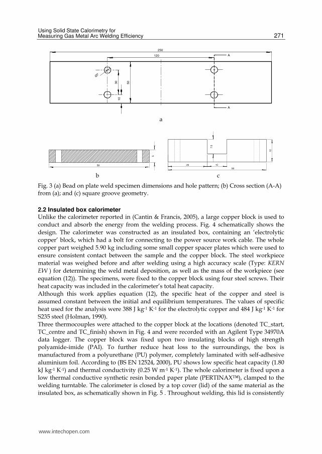
Fig. 3 (a) Bead on plate weld specimen dimensions and hole pattern; (b) Cross section (A-A) from (a); and (c) square groove geometry.
2.2 Insulated box calorimeter Unlike the calorimeter reported in (Cantin & Francis, 2005), a large copper block is used to
conduct and absorb the energy from the welding process. Fig. 4 schematically shows the
design. The calorimeter was constructed as an insulated box, containing an ‘electrolytic
copper’ block, which had a bolt for connecting to the power source work cable. The whole
copper part weighed 5.90 kg including some small copper spacer plates which were used to
ensure consistent contact between the sample and the copper block. The steel workpiece
material was weighed before and after welding using a high accuracy scale (Type: KERN
EW ) for determining the weld metal deposition, as well as the mass of the workpiece (see
equation (12)). The specimens, were fixed to the copper block using four steel screws. Their
heat capacity was included in the calorimeter’s total heat capacity.
Although this work applies equation (12), the specific heat of the copper and steel is
assumed constant between the initial and equilibrium temperatures. The values of specific
heat used for the analysis were 388 J kg-1 K-1 for the electrolytic copper and 484 J kg-1 K-1 for
S235 steel (Holman, 1990).
Three thermocouples were attached to the copper block at the locations (denoted TC_start,
TC_centre and TC_finish) shown in Fig. 4 and were recorded with an Agilent Type 34970A
data logger. The copper block was fixed upon two insulating blocks of high strength
polyamide-imide (PAI). To further reduce heat loss to the surroundings, the box is
manufactured from a polyurethane (PU) polymer, completely laminated with self-adhesive
aluminium foil. According to (BS EN 12524, 2000), PU shows low specific heat capacity (1.80
kJ kg-1 K-1) and thermal conductivity (0.25 W m-1 K-1). The whole calorimeter is fixed upon a
low thermal conductive synthetic resin bonded paper plate (PERTINAX™), clamped to the
welding turntable. The calorimeter is closed by a top cover (lid) of the same material as the
insulated box, as schematically shown in Fig. 5 . Throughout welding, this lid is consistently
www.intechopen.com

Arc Welding
272
manually moved along the welding direction, most closely following the welding torch (see
ΔS in Fig. 5) for reducing radiation and heat losses to the widest possible extent.
A typical temperature vs. time plot from the calorimeter is shown in Fig. 6. The temperatures converge on a steady state value between ~ 200 s and ~ 300 s, depending on the welding conditions. By examining the slope after convergence it is possible to estimate the average heat loss from the calorimeter as a function of time. The steady state temperature reading includes this effect.
Fig. 4. Sketch showing the design of the insulated box calorimeter (note: lid not depicted in this figure).
Note that items 1 - 10 in Fig. 4 are as follows:
1. Insulated box (aluminium foil laminated polyurethane) 2. Copper block 3. Weld specimen 4. Welding torch 5. Thermocouple (TC_start) 6. Thermocouple (TC_centre) 7. Thermocouple (TC_finish) 8. Polyamide-Imide insulating block 9. Copper connection to work cable 10. Bolt holes
www.intechopen.com

Using Solid State Calorimetry for Measuring Gas Metal Arc Welding Efficiency
273
Fig. 5. Schematic showing the operation of the insulated box calorimeter.
0
10
20
30
40
50
60
0 100 200 300 400 500
Time [s]
Te
mp
era
ture
[°C
]
TC_centre TC_finish TC_start TC_ambient
Fig. 6. Typical temperature vs. time plot. Note that the dashed circle shows when equilibrium is established.
3. Results
The average welding currents and voltages for the 5 conditions are shown in Fig. 7 (a). Pulsed GMAW-employs higher arc voltages but lower welding currents vs. CMT leading to comparably higher electrical average instantaneous power. The pulsed GMAW average instantaneous power was calculated approximately 1.6 higher than the corresponding CMT process for bead on plate geometry and 1.65 higher for square groove geometry. Fig. 7 (b) shows the average instantaneous power, qa, the measured average power delivered to the calorimeter, qi and the corresponding process efficiency. CMT shows only marginally increased efficiencies vs. pulsed GMAW, when applied to BOP welding and virtually no difference when applied to the square groove geometry. Regardless of which process was used, energy losses were found considerably decreased when applying the square groove design. For GMAW-P, this configuration allowed for reducing energy losses by ~ 37%, thereby improving the process efficiency to ~ 87%. With CMT the square groove design
www.intechopen.com

Arc Welding
274
could drop the energy losses by ~ 20%. The non-sandblasted groove surface condition was found to have no significant influence on thermal efficiency, compared with the sandblasted grooves.
0
25
50
75
100
125
150
175
200
225
GMAW-P BOP GMAW-P SG CMT BOP CMT SG CMT SG non-
sandblasted
Cu
rren
t [A
]; V
olt
ag
e [
V]
Average Welding Current Average Arc Voltage
a
0
1
2
3
4
5
6
GMAW-P BOP GMAW-P SG CMT BOP CMT SG CMT SG (non-sandblasted)
Po
we
r [k
W]
0,7
0,72
0,74
0,76
0,78
0,8
0,82
0,84
0,86
0,88
0,9
Eff
icie
ncy
[1]
Average Instantaneous Power Calorimetric Input Thermal Efficiency
b
Fig. 7. (a) Average welding current and arc voltages; (b) average instantaneous power, calorimetric power input and process efficiency for the welded specimens.
www.intechopen.com

Using Solid State Calorimetry for Measuring Gas Metal Arc Welding Efficiency
275
The weld bead shapes for the GMAW and CMT processes are shown in Fig. 8. This illustrates how the lower heat input with the CMT process leads to a narrower, more reinforced weld bead and less penetration (and lower dilution) of the substrate.
(a)
(b)
Fig. 8. Typical bead shape and transversal cross section for (a) pulsed GMAW and (b) CMT.
Although this fact is believed to be quite important, it seems yet to be often neglected in ‘low energy’ GMAW process discussions. This calorimetric study could basically approve a lower thermal energy input to the base material using CMT, leading to significant changes in bead shape and penetration behaviour with constant given conditions. Lower heat input is known beneficial for enhancing the process window and joining lower wall
www.intechopen.com

Arc Welding
276
thickness parts. Only focusing on the reduced energy input is believed, however, to neglect an important part of the whole physical process spectrum – inner and outer changes in the weld result.
4. Discussion
‘Controlled’ GMAW processes, such as CMT, are often considered capable of reducing the thermal energy input to the base material which has been demonstrated in this work. This work has shown that CMT supplies lower average voltage and different arc characteristics. The pulsed GMAW electrical parameters corresponding to the average wire feed speed of 8 m min-1 chosen in this study, produce an average instantaneous power which is similar to that from (Joseph et al., 2003) who used a wire feed speed of 7.62 m min-1. However the process efficiency in this work (77%) was much higher than that measured by (Joseph et al. 2003) 60%. It is supposed that the different calorimetric principle (liquid nitrogen), strongly affected by the transmission time, required to immerse the sample into the Dewar, may provide an explanation for the varying result. For GMAW-P BOP a heat input of ~ 0.38 kJ mm-1 and ~ 0.2 kJ mm-1 for CMT BOP, respectively, was found in this study, which was in very good agreement with (Pepe and Yapp, 2008). It was supposed in the present work, both processes, due to their different characteristics, would show considerably distinct energy losses. Interestingly however, they were found to have almost similar thermal efficiencies. The small arc efficiency increase with CMT BOP is believed to confirm the results from (Hälsig et al., 2010) and (Eichhorn and Niederhoff, 1972) assessing arc length reduction or short circuit affliction, respectively, as “efficiency increasing”. However, an efficiency of ~ 95% for short circuit arc welding as exceptionally stated by (Bosworth, 1991) with low deposition rate short circuit arc welding and ø 1.2 mm steel wire electrode could not be found in the present study; nevertheless reasonable good agreement with the efficiency results (~ 87% at ~ 4 kg h-1 deposition rate) could be proved for GMAW-P when welding in a square groove or “narrow gap” (Bosworth, 1991). Although the authors of this study acknowledge the influence of convection and/or vaporisation effects on welding efficiency, they unlike (DuPont and Marder, 1995) consider arc radiation rather the major reason for energy losses in GMAW. This is suggested due to the square groove results, which could prove the process efficiency to be significantly increased. It is believed the groove side walls are capable of capturing a considerable fraction of the energy regularly radiated away from the arc. As an interesting detail, the thermal efficiency values for CMT and GMAW-P become equal in magnitude when applying the square groove design, showing both processes to finally loose ~ 15% of their energy. This could indicate a stronger ‘compensation effect’ of particular groove configurations, e.g. square groove, for stronger radiating or higher performance processes. Besides changing arc radiation losses it might be assumed that also the remaining energy losses, such as convection, might be affected by specific groove designs. It is suggested however, that further investigation is needed in order to thoroughly explain the equivalence between GMAW-P and CMT when employing special groove configurations. Finally, the insignificance between sandblasted and non-sandblasted square groove conditions – having lower or higher side wall reflectivity, respectively – is suggested to be explainable due to either oxidation, generated by heat conduction in front of the arc, or general secondary physical importance in respect to the given conditions.
www.intechopen.com
Using Solid State Calorimetry for Measuring Gas Metal Arc Welding Efficiency
277
Calorimetry, as one assessment of this study, is considered an appropriate means in order to determine the interaction between arc and solid matter; confirming hereby the results from other researchers. An extensive amount of work in welding calorimetry has been conducted through the past decades supplying, however, quite different results joined to these experiments. It is considered likely that the noticeable spread in the results may arise from both “systematic and random errors” and especially the former can lead to “underestimates of the actual welding process” (Pepe et al. 2011). Nevertheless, Sievers and Schulz in (Kohlrausch, 1985) estimate – from a rather more physics viewpoint – even
“low complexity” calorimetry methods as being adjustable within an accuracy scatter of 1%. The grade of accuracy again is the main parameter for the final choice of calorimeter method and –type, respectively. According to (Kohlrausch, 1985), reducing the uncertainty in measurement e.g. toward 0.1% requires to rise the experimental complexity “exponentially” by “one ore even more orders of magnitude”. The insulated box calorimeter type, as used in this study, was applied for assessing two different approaches. First, gaining calorimetric data for an advanced or ‘controlled’ GMAW process (CMT), being unknown as yet. Secondly, if the calorimeter type, described in the present work, could provide an accuracy output similar to e.g. the Seebeck envelope calorimeter. As described GMAW-P efficiency results obtained in this study could show a reasonable good agreement with data from other researchers (DuPont and Marder, 1995 and Bosworth, 1991). The efficiency increase in short circuit arc welding, as stated by (Eichhorn and Niederhoff, 1972 and Hälsig et al., 2010) was also approved but was lower for the bead on plate welding conditions however, vs. the results stated by (Bosworth,1991). The CMT efficiency data are thus considered sufficiently accurate within the experimental and systematic scatter. As shown by (Pepe et al. 2011) an error of 1.5 for the insulated box calorimeter was comparable to the Seebeck envelope calorimeter as used in (Giedt et al. 1989), whereas an error of ~ 8% was found for the liquid nitrogen calorimeter as used in (Pepe et al, 2011). It is considered important to mention that the Seebeck envelope calorimeter efficiency measurements, as known from the literature (Giedt et al., 1989 and Fuerschbach and Knorovsky, 1991) are focused on autogenous gas tungsten- or plasma arc welding, respectively. It is also suggested important that, albeit a row of welding calorimetric investigation was carried out, the calorimeter types show a broad variety. This is considered to, at least in part, contribute to the scatter in the known efficiency data. Finally, the data, gained through this investigation, showed quite good agreement with both calculated and experimental results of (Sudnik et al., 2001). The authors have developed a mathematical GMAW-P model including the description of the heat source. Using a calorimeter type as with (Bosworth, 1991) for model verification applying different conditions, they could find a process efficiency of ~ 80% when adjusting a wire feed rate of 8 m min-1. It is believed that the welding calorimetry method, as used for this investigation, is capable of providing sufficient accuracy for measuring the process efficiency in much less time compared e.g. with the Seebeck envelope calorimeter type and with lower error compared with the liquid nitrogen calorimeter type.
5. Conclusions
An investigation on the accuracy and suitability of a self constructed solid state insulated box calorimeter for measuring and comparing the arc efficiency of controlled GMAW processes was conducted and the following conclusions were reached:
www.intechopen.com

Arc Welding
278
The solid state insulated box calorimeter showed precise measurements with both processes applied, and little random error. That is, it could be approved suitable for detecting also slight performance variations with low performance or controlled GMAW processes such as CMT.
At given experimental conditions and a wire feed speed of 8 m min-1, pulsed gas metal arc welding showed approx. 2 kW higher arc power in average vs. the CMT process.
The thermal efficiency with both processes was found slightly higher with CMT vs. GMAW-P when welding BOP, approving thereby the work of other researchers suggesting higher arc efficiencies for short circuit- or dip transfer.
Applying a square groove joint design was found capable of reducing radiation losses, hereby increasing considerably the arc efficiency. Almost equivalent average thermal efficiencies were found with both processes when welding in a square groove joint.
Further work seems necessary to explain this similarity of arc efficiency with both processes when applying the square groove joint design.
The insulated box calorimeter could show reasonable good agreement with efficiency data as known from other researchers and is believed to be a reasonable technological alternative in welding calorimetry vs. the Seebeck envelope calorimeter (higher measurement times) or liquid nitrogen calorimeter (greater experimental error).
6. Acknowledgements
The authors should like to acknowledge the generous permission of FRONIUS International Wels Austria to use equipment and facilities. Special thanks shall belong to Dipl.-Ing. Mr Andreas Leonhartsberger, who has constructed and built the insulated box calorimeter, and to Mr Gerhard Miessbacher, both with FRONIUS International Research & Development, for providing unselfish assistance throughout this investigation.
7. References
Bosworth, M.R. (1991). Effective Heat Input in Pulsed Gas Metal Arc Welding with Solid
Wire Electrodes, Welding Journal, Vol. 70, No. 5, pp. 111s-117s
British Standard EN 12524:2000 (2000). Building materials and products – Hygrothermal
properties – Tabulated design values
Cantin, C.M.D. & Francis, J.A. (2005). Arc Power and Efficiency in Gas Tungsten Arc
Welding, Science and Technology of Welding and Joining, Vol. 10, No. 2, 03/2004, pp.
200-210
DuPont, J.N. & Marder, A.R. (1995). Thermal Efficiency of Arc Welding Processes, Welding
Journal, Vol. 74, No. 12, pp. 406-s - 416-s
Eder, A. (2009), Private Discussion (unpublished)
Eichhorn, F., & Niederhoff, K. (1972). Streckenenergie als Kenngröße des Wärmeeinbringens
beim mechanisierten Lichtbogenschweißen (in German). Schweißen und Schneiden,
Jg. 24, H. 10, pp. 399-403
Evans, D., Huang, D., McClure, J.C., & Nunes, A.C. (1998). Arc Efficiency of Plasma Arc
Welds, Welding Journal, Vol. 77, No. 2, pp. 53s-58s
www.intechopen.com

Using Solid State Calorimetry for Measuring Gas Metal Arc Welding Efficiency
279
Fuerschbach, P.W. & Eisler, G.R. (1999). Effect of Very high Travel Speeds on Melting
Efficiency in Laser Beam Welding, SAE Transactions: Journal of Materials and
Manufacturing, Vol. 108, pp. 1-7
Fuerschbach, P.W. & Knorovsky, G.A. (1991). A Study of Melting Efficiency in Plasma Arc
and Gas Tungsten Arc Welding, Welding Journal, Vol. 70, No. 11, pp. 287s-
297s
Giedt. W.H., Tallerico, L.N. & Fuerschbach, P.W. (1989). GTA Welding Efficiency:
Calorimetric and Temperature Field Measurement, Welding Journal, Vol. 68, No.1.
pp. 28s-32s
Hackl, H. & Himmelbauer, K. (2005). The CMT-Process – A Revolution in Welding
Technology, International Institute of Welding, IIW Doc. No. XII-1875-05
Hälsig, A., Kusch, M., Bürkner, G. & Matthes, K.-J. (2010). Bestimmung von
Wirkungsgraden moderner Schutzgasschweißverfahren, IGF-No. 15.562B/DVS-
No. 03.078 (in German), Investigation of the Institute for production technology/
welding technology (Technical University of Chemnitz, Germany)
Holman, J.P. (1990). Heat Transfer (7th edn.), McGraw-Hill, ISBN 0-07-909388-4, San Francisco
(CA)
Hsu, C. & Soltis, P. (2002). Heat input comparison of STT vs. short-circuiting and pulsed
GMAW vs. CV processes, Proc. ASM Proceedings of the International Conference:
Trends in Welding Research, Pine Mountain, GA, USA, 15-19th April, 2002
Jenney, C.L., O’Brien, A. (Editors). (2001). Welding Handbook – Welding Science
and Technology, American Welding Society, ISBN 0-87171-657-7, Miami (FL),
USA
Joseph, A., Harwig, D., Farson, D.F. & Richardson, R. (2003). Measurement and calculation
of arc power and heat transfer efficiency in pulsed gas metal arc welding,
Science and Technology of Welding and Joining, Vol. 8, No. 6, 01/2003, pp. 400-
406
Kohlrausch, F., Hahn, D. †, Wagner, S. (1985). Kohlrausch Praktische Physik (in German), B.G.
Teubner, ISBN 3-519-13001-7, Stuttgart, Germany
Kou, S. (1987). Heat Flow during Welding, In: Welding Metallurgy, pp. 29-59, John Wiley &
Sons, Inc., ISBN 0-471-84090-4, Hoboken (NJ)
Kou, S. (2003). Heat Flow in Welding, In: Welding Metallurgy, pp. 37-62, John Wiley & Sons,
Inc. (2nd ed.), ISBN 0-471-43491-4, Hoboken (NJ)
Lancaster, J.F. (1986). The Physics of Welding, (2nd ed.), Pergamon Press, ISBN 0-08-030555-5,
Oxford (UK)
Lu, M. & Kou, S. (1988). Power and Current Distributions in Gas Tungsten Arcs, Welding
Journal, Vol. 67, No. 2, pp. 29s-32s
Nestor, O.H. (1962). Heat Intensity and Current Distributions at the Anode of High Current,
Inert Arcs, Journal of Applied Physics, Vol. 33, No. 5, (May, 1962), pp. 1638-1648, ISSN
0021-8979
Pepe, N. & Yapp, D. (2008). Process Efficiency and Weld Quality for Pipe Root Welding,
International Institute of Welding, IIW Doc. No. XII-1951-08
Pepe, N.C. (2010). Advances in Gas Metal Arc Welding and Application to Corrosion
Resistant Alloy Pipes, PhD Thesis, Cranfield University
www.intechopen.com

Arc Welding
280
Pepe, N., Egerland, S., Colegrove, P., Yapp, D., Leonhartsberger, A. & Scotti, A. (2011).
Measuring the Process Efficiency of Controlled Gas Metal Arc Welding Processes,
Science and Technology of Welding and Joining, Vol. 16, No. 5, (July, 2011), pp. 412-
417
Sudnik, V.A., Ivanov, A.V., & Dilthey, U. (2001): Mathematical model of a heat source in
gas-shielded consumable electrode arc welding, Welding International, Vol. 15, No.2,
pp.146-152
www.intechopen.com
Arc WeldingEdited by Prof. Wladislav Sudnik
ISBN 978-953-307-642-3Hard cover, 320 pagesPublisher InTechPublished online 16, December, 2011Published in print edition December, 2011
InTech EuropeUniversity Campus STeP Ri Slavka Krautzeka 83/A 51000 Rijeka, Croatia Phone: +385 (51) 770 447 Fax: +385 (51) 686 166www.intechopen.com
InTech ChinaUnit 405, Office Block, Hotel Equatorial Shanghai No.65, Yan An Road (West), Shanghai, 200040, China
Phone: +86-21-62489820 Fax: +86-21-62489821
Ever since the invention of arc technology in 1870s and its early use for welding lead during the manufactureof lead-acid batteries, advances in arc welding throughout the twentieth and twenty-first centuries have seenthis form of processing applied to a range of industries and progress to become one of the most effectivetechniques in metals and alloys joining. The objective of this book is to introduce relatively establishedmethodologies and techniques which have been studied, developed and applied in industries or researches.State-of-the-art development aimed at improving technologies will be presented covering topics such asweldability, technology, automation, modelling, and measurement. This book also seeks to provide effectivesolutions to various applications for engineers and researchers who are interested in arc material processing.This book is divided into 4 independent sections corresponding to recent advances in this field.
How to referenceIn order to correctly reference this scholarly work, feel free to copy and paste the following:
Stephan Egerland and Paul Colegrove (2011). Using Solid State Calorimetry for Measuring Gas Metal ArcWelding Efficiency, Arc Welding, Prof. Wladislav Sudnik (Ed.), ISBN: 978-953-307-642-3, InTech, Availablefrom: http://www.intechopen.com/books/arc-welding/using-solid-state-calorimetry-for-measuring-gas-metal-arc-welding-efficiency