Using Simulation to Improve the Efficiency of CAM and … · Using Simulation to Improve the...
15
Paper ID #6201 Using Simulation to Improve the Efficiency of CAM and CNC Instruction Dr. Derek M Yip-Hoi, Western Washington University Dr. Derek Yip-Hoi graduated with a Ph.D. from the University of Michigan in 1997. He has worked in academia since as both a research scientist and teaching faculty. He currently is an associate professor in the department of Engineering Technology at Western Washington University. His area of specialization is CAD/CAM. In addition to ASEE, he is a member of ASME and SME. c American Society for Engineering Education, 2013
Transcript of Using Simulation to Improve the Efficiency of CAM and … · Using Simulation to Improve the...

Paper ID #6201
Using Simulation to Improve the Efficiency of CAM and CNC Instruction
Dr. Derek M Yip-Hoi, Western Washington University
Dr. Derek Yip-Hoi graduated with a Ph.D. from the University of Michigan in 1997. He has worked inacademia since as both a research scientist and teaching faculty. He currently is an associate professor inthe department of Engineering Technology at Western Washington University. His area of specializationis CAD/CAM. In addition to ASEE, he is a member of ASME and SME.
c©American Society for Engineering Education, 2013

Using Simulation to Improve the Efficiency of CAM and CNC Instruction
Abstract
The use of industry-type CNC machines, as opposed to “trainers”, for learning NC
operations in Engineering Technology programs, presents several challenges. Key amongst these
is the potential for damage to the machine, tooling, work piece and injury to users from improper
operation. To prevent these occurrences, significant effort must be expended on the part of
instructors and lab personnel in vetting programming assignments completed by students, and in
supervising set-up and operation of a machine. Faced with fewer resources and increasing class
sizes, simulation techniques are becoming increasingly useful to help departments better manage
their resources, and not just for the educational benefit of the student.
This paper describes efforts to utilize simulation in several courses in a Manufacturing
Engineering Technology program that heavily utilizes CNC technology. To do this, accurate
digital models of CNC machines have been created using a CAD system, and converted into
simulation models within an industry standard NC verification application. For each of the
classes that utilize a CNC machine, the simulation model, along with tool and fixturing libraries,
are available for students to use in verifying the programs they create for assignments and project
work. Students are introduced to the simulation software at the start of an introductory course to
CNC operations, through a single homework assignment. The effort in using models is minimal:
Selecting tools from a library, adding and positioning stock geometry (and final part when a
machining accuracy comparison is required) in a fixture (often a Kurt machinist’s vice), setting
up the work coordinate system (G54 location), and loading the NC program. These steps mirror
those that will be performed by the student on the actual CNC, and so are reinforcing the
student’s experiences. Evidence of how the use of simulation is helping to increase the
preparedness of students, reduce the occurrences of programming errors and machine crashes,
and improve the efficiency of time spent in the lab will be presented.

Introduction
CAM and CNC technologies are important subjects in the training of Manufacturing
Engineering Technologists. A good grounding in these involves both learning the basic concepts
and applying these in various settings to fabricate parts and tooling. The CAD/CAM option in
the MET program at Western Washington University is designed to do just this. Students are
trained on industry-type CNC machines and utilize these extensively in project work for
fabrication. The program is committed to using industry-type equipment as opposed to CNC
trainers for the following reasons:
It develops confidence in students on the type of equipment they will encounter in practice.
Trainers can convey a false sense of security. Industry-type machines demand a greater
attention to safety.
A wider range of materials can be machined. Students learn to appreciate the role of a
material’s machinability in process planning.
Larger work envelops and spindle horsepower support a wider range of fabrication
possibilities. For example, machining of molds.
Better exposure is provided to the challenges in selecting tooling and fixtures.
Students develop a better understanding of the proper selection of process parameters
(speeds, feeds and depths-of-cut) and the trade-offs as materials and conditions change.
A better appreciation for the challenges in achieving dimensionally accurate parts is
obtained.
Students acquire a more realistic understanding of the efficiencies of machining processes
This heavy use of industry-type CNC equipment does present serious challenges to the
instructors and technical staff in the department. Proper management and supervision of their use
is essential if these resources are to be maintained, and students are to develop the correct skills
and attitudes as operators.
To assist in this, the program has moved decidedly towards the use of simulation to assist
students in learning CAM and CNC programming concepts and most importantly for program
verification before deployment. The idea is to duplicate as much as possible in a university
setting what is becoming standard in industry, where simulation for NC verification is
approaching the point where “lights-out machining” is being practiced1. There is such a high
level of confidence in the use of verification techniques, that programs can be directly deployed
to CNC machines with little if any operator input2. A similar use of simulation can help mitigate
some of the disadvantages of university CNC laboratories utilizing industry-type CNC
equipment as opposed to CNC trainers. If a similar goal to “lights-out machining” can be
realized in university labs, then a greater range, and more sophisticated uses of CNC equipment
is possible. This would occur without the need for increases in instructional resources, or the risk
of injury and equipment damage.
An instructional approach with a heavy component in simulation can better prepare MET
graduates for using and advancing this technology in industry. From a pedagogical perspective,
simulation is often viewed as “something to expose a student to”, one of several skills that are to
be acquired in a CNC course. However, with current advances in IT, simulation should also be
viewed as an enabler of learning. A properly developed and integrated simulation environment
can be used by the instructor to explain programming concepts during lectures and labs, and for
assisting with assessment. It can be used by students to help develop and hone their skills when
completing homework assignments and in preparing for machining labs. A simulation
environment can provide a level of instantaneous feedback to students that can be helpful when
the instructor is not readily available. Using portable electronic devices, simulation can be made
available at the machine tool to assist instructors and technicians in validating and fixing
programs.
In the next section, a brief review of related work will be presented. This will be followed
by an overview of how a verification methodology utilizing the industry standard Vericut®3
software has been developed and deployed in the curriculum.
Review of CNC Verification Technology and Educational Applications
A significant body of research exists on the development of CNC Verification
methodologies. This dates back to the early 1980s when solid modeling and computer graphics
techniques were adopted to simulate the material removal processes. Gossard and Tsuchiya4 and
Volecker5 both investigated the feasibility of using boolean operations in newly developed solid
modeling systems to subtract tool swept volumes from a work piece. It was however the use of
Z-buffers and Z-maps from computer graphics, to store changing depths at discrete locations
from an engaged cutter, that proved to be most promising. This was first investigated by Wang6
and Van Hook7 in 1986 with extensions to discrete vector based methods by Jerard
8 and Oliver
and Goodman9 in the late 80s and early 90s. The commercial verification systems of today such
as Vericut® are almost exclusively based on a variant or combination of these discrete
techniques.
In the area of education applications, research has been presented on the development of
virtual CNC simulators that can be used in training. These include work by Ong et al.,10
Wang et
al.11
and He et al.12
. These simulators are developed using building blocks that in most cases
have been created and integrated by the authors. In some cases they provide unique capabilities
such as allowing users to measure cutting forces during machining10
. However, these papers
focus mostly on describing the development and capabilities of these tools. Little is reported in
these cases on the deployment and impact in the curriculum. Djassemi13
does report on an
experience in developing a hands-on approach to CAD/CAM instruction that does include
verification. While he presents some assessment of the approach based on a exit survey given to
students, it is general and does not specifically target the impact of the use of the verification
tool. It is also unclear from this paper the type of tool used and the detail required from the
students in validating their programs.
A search in Google Scholar using the key phrase “Vericut Educational Applications” returns
numerous articles written by Chinese authors that illustrate strong interest in using this particular
software tool in that country. Some articles not written in Chinese that highlight use of this
particular tool are by Pritschow and Rock14
, Adamski15
and Wu et al16
. As before, none of this
work appears to focus on the impact on CNC resource utilization in an educational setting or the
curriculum.
While there is unmistakedly merit to developing custom simulation tools in a university
setting to assist in training, there are certain advantages to the approach described in this paper of
using a commericially developed and supported system. First, one can focus more on how to use
the application rather than be embroiled in the challenges of developing it. The sophisticated
nature of commerical systems makes their setup and efficient use in an educational setting a non-
trivial matter as this paper illustrates. Commercial systems often have a higher level of
robustness over prototype systems as they must satisfy industry uses which demand that the
technology work correctly when needed. Thus, less time is spent in fixing bugs or limiting use to
work around deficiencies in the tool. A broadly used commercial tool such as Vericut®
, also has
a rich user and knowledge base that can be tapped to solve problems and to share models and
findings. Finally, students are being exposed to a tool that they will likely encounter again in
their future careers. This is important in the training of technologists, and it is a benefit for them
to indicate this experience when they search for work.
The Role of CNC Machining in the Curriculum
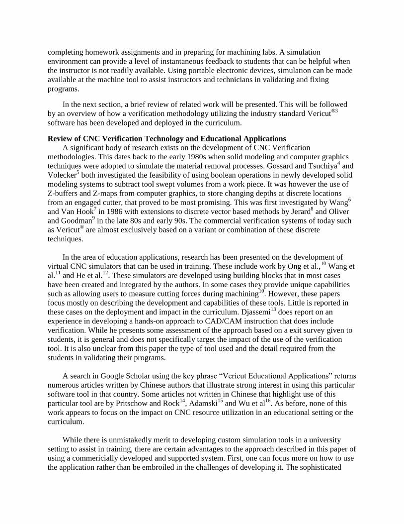
CNC plays a significant role in the curriculums of both the MET and PET programs that are
offered by the ET department. This technology is important both as a primary learning objective
and in supporting other classes where fabrication of products and tooling is important. Figure 1
illustrates where CNC is used in the curriculum for MET students specializing in CAD/CAM.
This experience differs in the senior year for students who are taking the core MET or PET
majors. All students get a brief introduction to CNC technology in ETEC 246. This involves
running programs for machining hole patterns on a part that each student must fabricate during
their lab sessions. Though this program is written by the instructor, students are given a quick
description of what it does, and an overview of G&M programming. They are required under
supervision to setup their workpiece, and operate a CNC machine to execute this program.
Through this experience, they are able to get a sense of the benefits of automated machining over
performing manual operations which constitutes the bulk of their laboratory experience in this
class.
Figure 1. Use of CNC in the CAD/CAM Curriculum
Intensive instruction for all MET and PET students in manual part programming and the
operation of CNC machines, takes place in ETEC 322. Students are also exposed to CAM using
the Prismatic Machining workbench in CATIA® and Vericut
® for NC verification. The
laboratory experience in this class involves setting up and running programs (both manual and
CAM generated) to machine components that assemble into a mantel clock (see Figure 6). An

advanced CNC class (ETEC 426) is required for all CAD/CAM majors and available as a
technical elective for others. It has several flavors, the one most relevant to this paper being
Surface Machining. This expands the CAM experience in ETEC 322 to 3-Axis and 5-Axis
machining. As in ETEC 322, the laboratory experience involves setting-up and operating a CNC
machine. Beyond these classes, where learning CAM and CNC are the primary objectives, there
are other places in the curriculum where use of the technology is required to complete projects.
For CAD/CAM and PET majors, ETEC 335 is an injection mold design and fabrication class.
Project work here requires student teams to design and machine an injection mold that will be
used to produce plastic parts (see Figure 2). Finally, some though not all students may utilize
CNC machines for fabrication work as part of their capstone Senior Project (ETEC 422 and 424).
Figure 2. Examples of Molds Machined in ETEC 335
The requirements for project work in ETEC 322, 426, 335 and 422/424 place high demands on
the four machines in the department’s CNC laboratory. The use of verification technology is one
way to reduce the amount of on-machine programming changes needed, identify errors and
streamline the procedures that students must follow before being allowed to execute their work
on a machine.
Developing and Deploying the Verification Models
A multi-level development strategy was used to create the verification models for the CNC
curriculum. This is shown in Figure 3. The first level focused on the piece of the model that can
be used across all classes where CNC is taught or utilized. Key activities required at this level
were building the CAD model of the machine tool, creating its kinematic structure and adapting
a controller for parsing and executing G&M code programs. One of the challenges in building
the 3D CAD model, was obtaining accurate measurements of the CNC machine. Initially, a
search was made for the availability of a CAD model for a Haas VF2 milling machine. This
proved fruitless. Inquiries brought to light the fact that while machine tool venders likely have

created such models, in most cases and probably with good reason, they are reluctant to
distribute them. As a result, hand measurements of the machine and tracing of scanned
documentation were the methods used. Figure 4 shows the final CAD model created. The
machine’s work envelop was the focus for the greatest accuracy and level of detail. Within this
volume, sizes and locations within ¼” were realized.
Figure 3. Multi-Level Development Strategy for Verification Models
Figure 4. Modeling of a Haas VF2 CNC Milling Machine

At the next level, models relevant to a particular class were developed. These include tooling and
fixturing libraries, and the initial work piece geometry if predetermined by the instructor. Finally,
at the assignment level students typically need to model the final part geometry and sometimes
the initial work piece when this is not given to them. They also need to select or modify fixturing
elements. For many assignments, a machining vice with parallels are used. A parametric CATIA
CAD model where the jaw spacing can be adjusted is provided for this. After process planning
and the completion of the part program, a modified tooling file containing a subset of tools from
the class tooling library is created by the student. The final Vericut® model is consequently an
integration of models and data obtained from all three levels described.
Figure 5. Management of Verification Models Across Classes, Assignments and Student Users
Figure 5 illustrates how the verification models are deployed in the department’s CAD/CAM
laboratory. The intructors create class directories on the lab server for each class that requires use
of a CNC machine. In each class directory, assignment folders are created that contain Vericut®
project and tooling files, geometry files for fixtures, the final part geometry (if provided) and the
work piece geometry. The machine tool model that is made up of the 3D component geometry,
the machine’s kinematic structure and the controller for parsing and executing part programs, are
built by the instructor, tested and installed locally on the laboratory’s computer image which is
installed on all 50 lab machines at the beginning of each quarter. It should be noted that all
geometry files in Vericut® are stored in the .STL format.
To use a model, each student taking the class in question will copy into their personal directory
the files in the assignment directory on the server. When they run the Vericut® project file, it will
build the simulation model using the locally stored machine tool model and the files in the
student’s directory on the server that define assignment specific tooling, fixtures, work piece,
final part geometry and part programs.
Dividing the model between server and local storage in this way is important. Depending on the
level of detail the machine tool model can easily be over 10 Mb in size and made up of 20 to 30
separate geometry files. Having students store and use their own versions of this complex model

profilerates data on the server, and invariably leads to wasted time in fixing broken models that
have been poorly managed. This approach allows students to focus on an assignment’s part
programming requirements, with the use of the verification model being similar to setup and
running a program on a CNC machine, though in a virtual sense. Updates to a model are also
easy to make at any time by the instructor on the image for deployment to all lab computers.
Enhancing Student Preparations for Laboratory and Project Work
In this section, the use of the verification model to enhance preparations for project work in
ETEC 322 is described. Students in this class complete a number of labs and a final project that
machine the components of a mantel clock from aluminum stock. Figure 6 shows an example of
the components, final assembled product along with a listing of the labs that are used to machine
each component.
Figure 6. ETEC 322 Manually and CAM Programmed Components and Final Result
Prior to machining a component, each student must complete and provide documentation of the
following:
Design Work: This is needed for the final project where students are to design an engraving
pattern to be machined on the clock face. A part drawing of the engraving must be created.
Process Planning: Process Sheets are required for each setup showing a list of operations,
tools, speeds and feeds that are used. The also include a sketch of the setup identifying the
location of the part origin and the axes orientations (G54).
Part Programming: Either manual or CAM generated programs depending on the
assignment.
Digital Verification: This shows the execution of the part program for each setup that must
be machined using the complete Vericut® model described previously. This verification does
two important things. First, it helps to identify rapid or unintended moves that result in
collision between the tool, work piece and fixture. Second, by comparing the machined stock
to the design, students verify that the program is cutting the correct geometry.
Review of Preparations: A CNC Preparation Check Sheet must be completed for each
assignment. This is used to confirm to the instructor that the student has completed all
preparation steps. This includes reviewing code for simple errors such as missing decimal
points (e.g. F20 means a feed rate of 0.002 ipm) or mismatched values for tool length and
diameter compensation (e.g. T10 requires H10 and D10). For the final project, a check-off
with the instructor in the CAD/CAM laboratory is required ahead of the scheduled
appointment on the CNC milling machine.
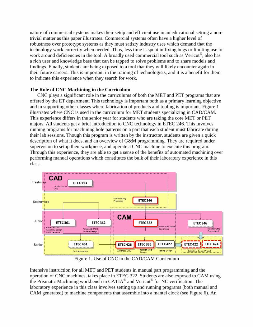
Figure 7. Examples of Verification for ETEC 322 Final Project and Identification of
Programming Errors
Figure 7 shows an example of the results obtained from the verification step for the two set-ups
required for the final project (Lab 8). The appearance of “red” during the simulation indicates a
rapid move into material or any contact of components that is not strictly either the flutted length
of the tool or the work piece material e.g. cutter and vice or tool holder and work piece. During
manual part programming, this often occurs when students forget to switch back to feed motion
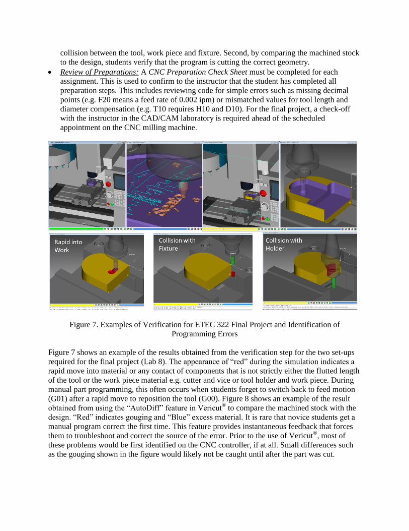
(G01) after a rapid move to reposition the tool (G00). Figure 8 shows an example of the result
obtained from using the “AutoDiff” feature in Vericut® to compare the machined stock with the
design. “Red” indicates gouging and “Blue” excess material. It is rare that novice students get a
manual program correct the first time. This feature provides instantaneous feedback that forces
them to troubleshoot and correct the source of the error. Prior to the use of Vericut®, most of
these problems would be first identified on the CNC controller, if at all. Small differences such
as the gouging shown in the figure would likely not be caught until after the part was cut.
Figure 8. Example of the use of the AutoDiff feature in Lab 4 to indicate gouging (red) and
excess material (blue) motions in program
Use of Verification Technology as an Instructional Tool
In addition to the use of this technology by the student to assist in lab and project
preparations, the instructor also makes use of it during lectures to assist in explaining manual
programming concepts. In ETEC 322, several examples have been prepared that cover the range
of topics from linear interpolation through cutter compensation and sub-programming.
Previously these examples were explained using a combination of Powerpoint slides and writing
on a “Whiteboard”. Now students can see in realtime projected on a screen, the simulation
execute each command in a program. The single step feature in Vericut® allows the instructor to
explain how each block of code is executed before proceeding to the next. These examples are
also saved in the class directory so that they can be retrieved by students as they review material
presented during a lecture.
Evidence of Impact
This evidence comes from observations by the instructors and technical staff and from
student feed back. It is divided into (1) impact on efficiency of use of laboratory time, (2)
reduced damage to equipment and tooling, and (3) providing learning assistance for students.
Efficiency of Use of Laboratory Time: Recent curriculum changes have resulted in both the
reduction of scheduled CNC lab times in ETEC 322 from three to two hours, and a doubling of
section sizes from six to twelve students. The latter change was accommodated by operating all
four CNC machines during a lab session, as opposed to just two that were used in the past. This
increases the supervision load on the two instructors assigned to the section. There was
significant concern that these two changes would make these laboratory sessions extremely
difficult to manage. However, this has not been the case. Over the past three terms that this
course was taught, with the incorporation of the verification procedures described previously,
over 85% of laboratory sessions and 95% of project sessions were completed within the allotted
2 hour period. In those cases when students ran long, the problem was typically due to a setup
error on the machine requiring a rerun e.g. incorrect tool length measurement, improper location
of G54, poor seating or clamping of the work piece. Previously when sessions were 3 hours long,
a significant portion of this time would be spent fixing programming errors on the controller.
Instructors agree that with the requirement to verify before machining, programs are a lot
“cleaner” when students arrive to do their lab work. Fewer major programming fixes are needed
on the controller. As a result, even with twice as many students in the lab, twice the number of

machines running and 50% less time, the intensity and stress level for instructors as they guide
students through the labs, is significantly lower than was previously the case.
Figure 9. Student Feedback on Avoiding Programming Errors
Reduced Damage to Equipment and Tooling: Though exact numbers are not available,
instructors agree that the number of serious machine crashes resulting in broken tooling and
scrapped work pieces is significantly lower. During the most recent offering of the course, only
one incident was recorded were a tool was rapided through the work piece resulting in tool
breakage. Upon investigation it was discovered that the students in question missed, or ignored,
the results from the simulation which clearly showed a “red” rapid move. Further evidence of
impact in this area came from a survey of students at the end of the term. Figure 9 shows that
over 90% of the students agreed that Vericut® helped them avoid a programming error that could
have resulted in a machine crash.
Figure 10. Other Student Feedback on the Impact of Using Vericut
®
Providing Learning Assistance for Students: The use of simulation models during lectures has
already been explained. Students overwhelmingly agreed that this technique was helpful to them
in developing an understanding of programming concepts (see Figure 10, Q15). Further, they
also agreed that this helped them identify and correct coding problems on their own (Q14). The
ability to get instantaneous feed back on their coding, changes the dynamic of how they tackle
and complete assignments. Motivated to learn and do well, this technique gives them the means
to take some corrective action to improve their work when previously this was not the case.
Many in the past would not have critically checked their work, or even if they had, be
knowledgeable or thorough enough to identify many problems present. By being able to engage
in validate and update improvement iterations without the direct involvement of the instructor
(an impossibility given time constraints), students are encouraged to learn from the mistakes they
have made and the fixes they create, as opposed to blindly accepting the first solution they
generate. Finally, the majority of students agreed that the benefit of having this tool available for
use, outweighed the effort needed in learning how to use it (Q16).
Discussion and Future Directions
The evidence suggests that the application of verification technology as described in this
paper has positively impacted the efficiency of CAM and CNC instruction. Further, it has led to
a reduction in machine crashes which is important in protecting the investment made in
expensive, industry-type CNC machines. While preliminary indications are that this technology
also assists students in learning CNC programming concepts, further study is needed to confirm
this. One cause for concern parallels that raised on the impact of calculators in developing
mathematics skills. Does the availability of the verification tool make students less inclined to
commit to memory the syntax, structure and methods of G&M code part programming? With
most materials being provided electronically, it is evident that most students “cut-and-paste”
code between examples and assignments once they have access to these. In many cases this
makes sense, and is encouraged, as it increases programming speed and minimizes errors
assuming that the source is correct in the first place e.g. code for program start-up and tool
change blocks. However, if this happens before an understanding of how the words in each block
function, then the learning process is short circuited.
Vericut® allows programs to be simulated while being written. Thus, the affect of each block of
new code can be visualized before moving on to programming the next step. While using this
capability seemed like a good idea at first, it was quickly discovered that some students were
getting incorrect results from the simulation and getting stuck spending a lot of time trying to fix
code that was actually correct. This problem arose because Vericut®, like a CNC controller often
needs to look a block or two ahead to correctly execute the commands in the current block. With
a proper understanding of when and how this happens, simultaneously writing and simulating
blocks of code could be an effective means of programming. However, given the relative
inexperience of students, to avoid this problem it was strongly recommended that they complete
manual coding of their entire program before performing verification.
As with other software tools that analyze or simulate, there is a danger of blindly accepting
results that contain significant errors. It has already been described how lack of attention to the
results during a simulation by students, led to a machine crash with a broken tool and scrapped
part. Also, the model in its current form, will sometimes correctly cut geometry in a block of
code that will generate an alarm on the CNC controller. It does not catch mismatched H and D
values that are used to call up tool length and diameter offsets, numbers with missing decimal
points that are interpreted as ten thousandths of an inch, or collisions with tool holders as tool

extensions are currently not standardized and captured in the model. Some of these problems will
be eliminated in time by enhancements to the model. However, students are continually
reminded that there are limitations, and are given a check list to be completed during a final
review of their code that is designed to help them identify and fix problems that have been
missed. The excuse “It worked correctly in Vericut!” is not tolerated.
For future work, a couple of areas are targeted:
Expansion of the model to include 5-axis capabilities: This step supports the objectives of
ETEC 426a, the advanced CNC surface machining class. Students learn use of the multi-axis
machining capabilities present in the CATIA®
Surface Machining workbench. They are
required to complete a project that machines a part using programs generated from this
workbench. Due to the to absence of a 5-axis machine in the CNC lab, this has been limited
to 3-axis tool paths, even though they learn how to program 5-axis operations. However, with
the availability of the simulation models that have been developed to-date, a team-based
extention to this project is being planned that will require the following:
o Expanding the 3-axis Haas VF2 mill to enable 5-axis machining capabilities by modeling
and integrating a trunion table. Figure 11 shows an example of the modeling detail
needed to do this.
Figure 11. Expanding Haas VF2 to a 5-Axis Mill
o Replacing the finishing operations on the 3-axis project with 5-axis operations.
o Simulating and verifying the 5-axis tool paths using the enhanced 5-axis milling model.
Though not a complete experience due to the absence of a real 5-axis machine, it is hoped
that by expanding the simulation model and reworking their part programs, the students will
develop a better appreciation of how such a machine functions.
Developing a Simulation Model for the Department’s Mazak Mill/Turn Machine: As can be
seen from Figure 6, Lab 2 requires the use of a Mazak Mill/Turn machine to create spindles
for the ETEC 322 clock project. Mill/Turn machines are both difficult to program, and with a
fast moving turrent fully loaded with tools, have a high potential for collisions. A project is
currently underway to develop a simulation model for this machine. This will allow greater
use of the milling capabilities of this machine in classes and for projects. It will also allow
this machine to be more efficiently programmed off-line using a CAM application such as
CATIA’s Mill/Turn workbench.

Conclusions
In this paper, a description of the development and deployment strategy for verification
technology in a curriculum where CNC is taught and heavily used has been presented. The
commercial system Vericut® was adopted over a custom, in-house solution so that the focus
could be on managing the use of the technology rather than on development issues. The approach
has resulted in a realistic and sophisticated model of the department’s Haas VF2 CNC milling
machines being used for multiple assignments and projects across several classes in the
curriculum. This model has been set up for ease of maintenance and to allow it to be customized
quickly for different assignments and classes. It is also being used for basic instruction during
lectures to assist students as they learn basic CNC programming skills. Initial evidence suggests
greater efficiency in the use of CNC machines and a reduction in machine crashes as a result.
There is also reason to believe that the availability of simulation is assisting students in learning
programming concepts though this needs to be investigated further. New and expanded models
are being developed for other types of CNC machines that will further extend the use of this
technology in the curriculum.
Bibliography
1. Bates, C., “Fast Setups, Short Runs and Lights-Out Machining”, American Machinist, December 29th
, 2009,
http://americanmachinist.com/automation/fast-setups-short-runs-and-lights-out-machining.
2. “Simulation Software Enables “Lights-Out” five-axis machining”, Modern Machine Shop, December 3rd,
2007,
http://www.mmsonline.com/articles/simulation-software-enables-quotlights-outquot-five-axis-machining.
3. Vericut®, CGTECH, www.cgtech.com, 2013.
4. Gossard, D.C., Tsuchiya, F.S., “Application of set theory to the verification of NC tapes”, Proceedings of the
North American Metalworking Conference, April 1978.
5. Voelcker, H.B., Hunt, W.A., “The Role of Solid Modeling in Machining, Process Modeling and Verification”,
SAE Technical Paper 810195.
6. Wang, W.P., Wang, K.K., “Real-time verification of multiaxis NC programs with raster graphics”, Proceedings
of the IEEE International Conference on Robotics and Automation, San Francisco, April 7-9th
, 1986, pp. 166-
171.
7. Van Hook, T., “Real-time shaded NC milling display”, Computer Graphics, The Proceedings of SIGGRAPH,
August, Vol 20 (4), 1986, pp. 15-20.
8. Jerrard, R.B., Drysdale, R.L., Hauck, K., Schaudt, B., Magewick, J., “Methods for detecting errors in sculptured
surface machining”, IEEE Computer Graphics and Applications, Vol. 9 (1), 1989, pp. 26-89.
9. Oliver, J., Goodman, E.D., “Direct dimensional NC verification”, CAD, Vol. 22 (1), 1990, pp. 3-10.
10. Ong, S.K., Jiang, L., Nee, A. Y. C., “An Internet-Based Virtual CNC Milling System”, International Journal of
Advanced Manufacturing Technolology, Vol. 20, 2002, pp. 20–30.
11. Wang, X., Zheng, P., Wei, Z., Sun Y., Luo, B., Li, Y., “Development of an Interactive VR Training for CNC
Machining”, VRCAI 2004 - ACM SIGGRAPH, International Conference on Virtual Reality Continuum and its
Applications in Industry, pp. 131-133.
12. He, H., Wu, Y., “Web-based virtual operating of CNC milling machine tools”, Computers in Industry, Vol. 60
(9), December 2009, pp. 686-687.
13. Djassemi, M., “A HANDS-ON APPROACH TO TEACHING CAD/CAM FOR MANUFACTURING AND
RAPID PROTOTYPING APPLICATIONS”, The Proceedings of the American Society for Engineering
Education Annual Conference & Exposition (on CD), June 24-27, 2007, Honalulu, Hawaii, 9 pages.
14. Pritschow, G., and S. Röck. "“Hardware in the Loop” Simulation of Machine Tools." CIRP Annals-
Manufacturing Technology 53.1 (2004): 295-298.
15. Adamski, W. (2010). Manufacturing Development Strategies in Aviation Industry. Advances in Manufacturing
Science and Technology, 34(3), 73-84.
16. Wu, Yu Hou, Qiang Gao, and De Hong Zhao. "UG and VERICUT-Based Processing of Special-Shaped Stone
Samples." Advanced Materials Research 415 (2012): 924-928.