Using Microstation V8i Drafting Tools - Connecticut · · 2010-09-28tools in Microstation V8i....
22
Page 1 of 22 MicroStation V8i Detailing Tools 9/26/2010
Transcript of Using Microstation V8i Drafting Tools - Connecticut · · 2010-09-28tools in Microstation V8i....

Page 1 of 22
MicroStation V8i Detailing Tools 9/26/2010

Page 2 of 22
Table of Contents
MICROSTATION V8I DETAILING TOOLS.......................................................................................................1
SECTION 1 LINK SET .............................................................................................................................4
1.1 What is a Link Set? .......................................................................................................................................4
1.2 Link Set Creation ..........................................................................................................................................4
SECTION 2 MODEL PROPERTIES ........................................................................................................6
2.1 New 2-D Sheet Model ....................................................................................................................................6
2.2 Existing 2-D Sheet Models ............................................................................................................................7
SECTION 3 PROJECT EXPLORER ........................................................................................................7
3.1 What is Project Explorer ..............................................................................................................................7
3.2 Adding Sheet Models to the Link Set ..........................................................................................................8
3.3 Renumbering Sheet Models..........................................................................................................................9
SECTION 4 DETAILING SYMBOLS....................................................................................................10
4.1 Placing Section Callout ...............................................................................................................................10
4.2 Section Title .................................................................................................................................................12
4.3 Detail Callout ...............................................................................................................................................16
4.4 Placing Drawing Title .................................................................................................................................17
SECTION 5 LINKING DETAIL AND SECTION CALLOUTS TO DRAWING TITLES ...................18
5.1 Linking the Section/Detail Callout and Section Title From the Same Contract Sheet..........................18
5.2 Linking the Section/Detail Callout to a Title From one Contract Sheet to Another .............................20

.21
Page 3 of 22
The following workflow details the procedure for using project explorer and using the detailing tools in Microstation V8i. By following this workflow all of the detailing tools will be linked together so if the sheet number’s change all section cuts, detail callouts, and title text bubbles will be updated automatically.
Page 4 of 22
Section 1 Link Set
1.1 What is a Link Set? A link set is a way to organize project data and helps in the creation of links between all this data. These links created in Microstation will still be active after a PDF is created. The link set can include, but is not limited to Contract Sheets, Specifications, Quantity Estimates, and Contractor Submittals.
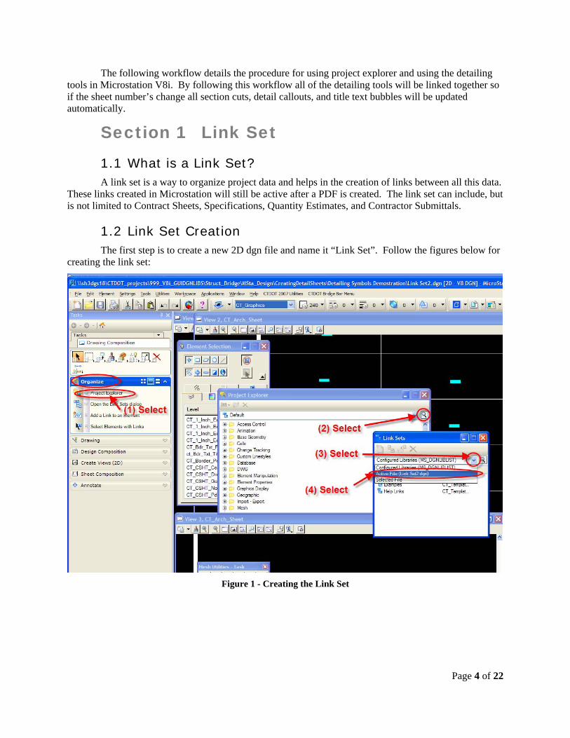
1.2 Link Set Creation The first step is to create a new 2D dgn file and name it “Link Set”. Follow the figures below for creating the link set:
Figure 1 - Creating the Link Set

Figure 2 - Creating the Link Set
Page 5 of 22
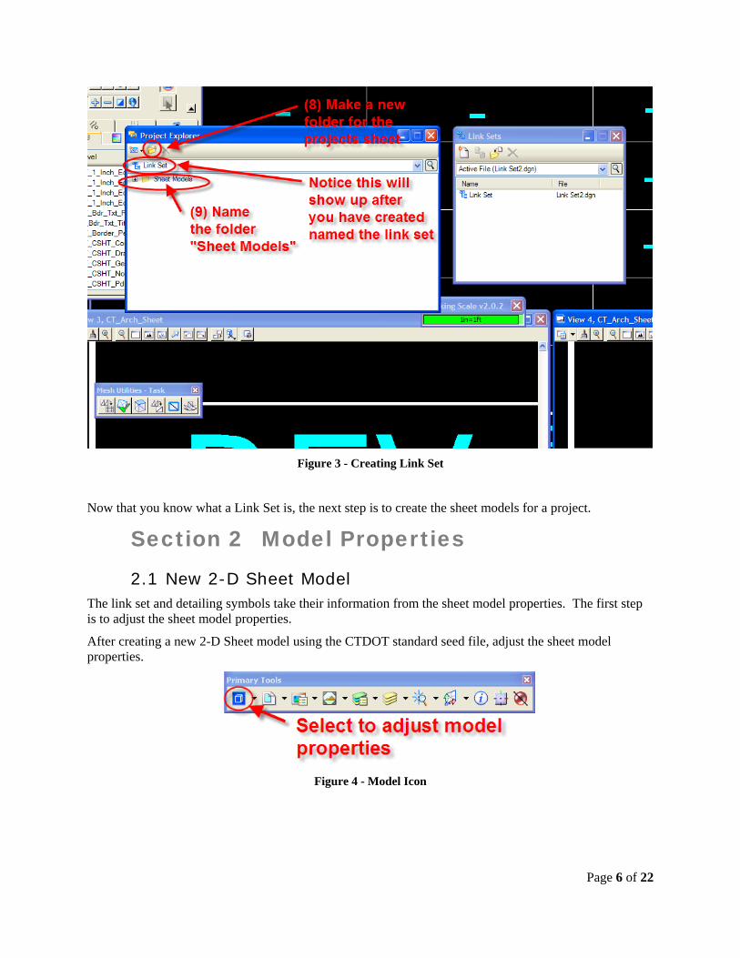
Figure 3 - Creating Link Set
Now that you know what a Link Set is, the next step is to create the sheet models for a project.
Section 2 Model Properties
2.1 New 2-D Sheet Model The link set and detailing symbols take their information from the sheet model properties. The first step is to adjust the sheet model properties.
After creating a new 2-D Sheet model using the CTDOT standard seed file, adjust the sheet model properties.
Figure 4 - Model Icon
Page 6 of 22
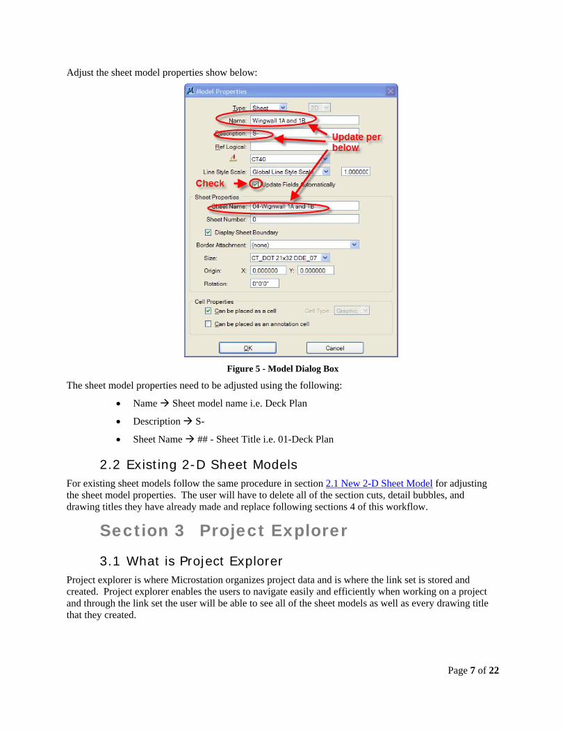
Adjust the sheet model properties show below:
Figure 5 - Model Dialog Box
The sheet model properties need to be adjusted using the following:
Name Sheet model name i.e. Deck Plan
Description S-
Sheet Name ## - Sheet Title i.e. 01-Deck Plan
2.2 Existing 2-D Sheet Models For existing sheet models follow the same procedure in section 2.1 New 2-D Sheet Model for adjusting the sheet model properties. The user will have to delete all of the section cuts, detail bubbles, and drawing titles they have already made and replace following sections 4 of this workflow.
Section 3 Project Explorer
3.1 What is Project Explorer Project explorer is where Microstation organizes project data and is where the link set is stored and created. Project explorer enables the users to navigate easily and efficiently when working on a project and through the link set the user will be able to see all of the sheet models as well as every drawing title that they created.
Page 7 of 22

3.2 Adding Sheet Models to the Link Set After opening a sheet model follow the figures below to add that sheet model to the project link set:
Figure 6 - Link Set
Figure 7 - Link Set
Page 8 of 22
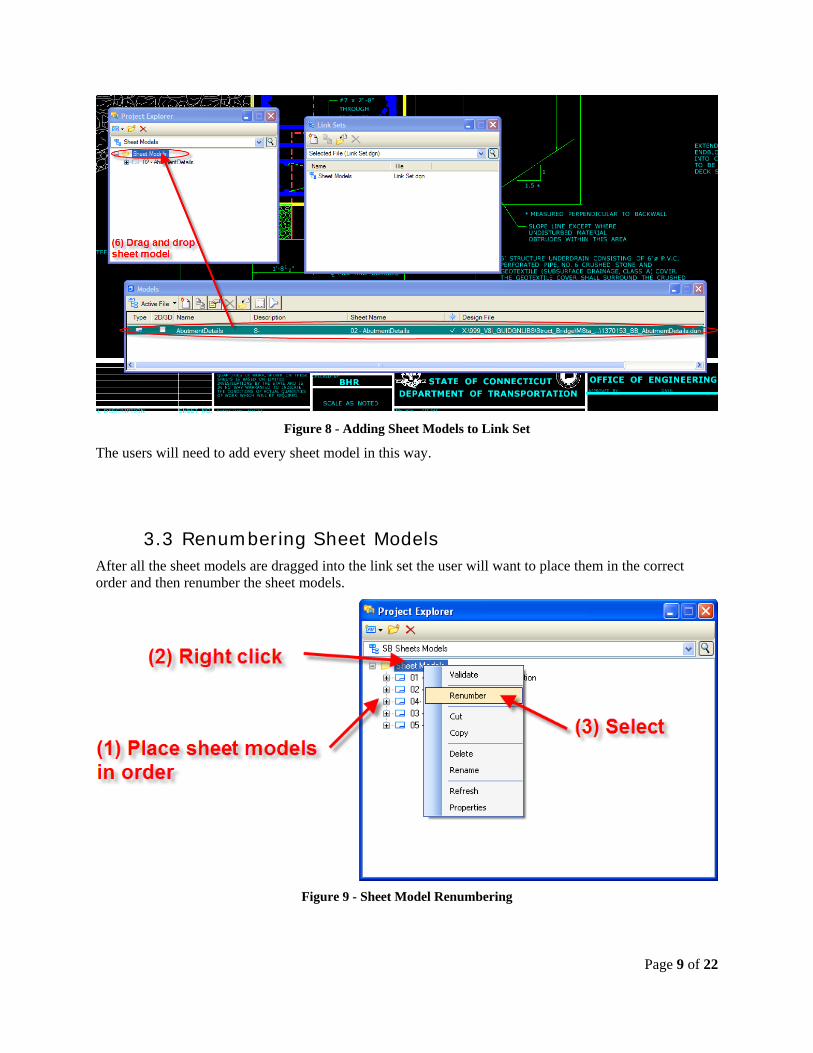
Figure 8 - Adding Sheet Models to Link Set
The users will need to add every sheet model in this way.
3.3 Renumbering Sheet Models After all the sheet models are dragged into the link set the user will want to place them in the correct order and then renumber the sheet models.
Figure 9 - Sheet Model Renumbering
Page 9 of 22

Page 10 of 22
Now that the sheet models are numbered correctly, the section callouts, detail callouts, and drawing titles must be updated. This is done by using the update all fields icon shown in Error! Reference source not found..
Section 4 Detailing Symbols
4.1 Placing Section Callout Follow the figure below for placing a section callout.

Figure 10 - Place Section Callout
Below is the section callout that was created. The text shown in the section callout bubble is where the information is being taken from. Do not edit the text fields; this will be done automatically after the title for the section is made.
Page 11 of 22

Figure 11 – Section Callout
4.2 Section Title Follow the figure below for placing a section title.
Page 12 of 22

Figure 12 - Place Drawing Title
Below is the drawing title that was placed:
Page 13 of 22

Figure 13 - Drawing Title
The drawing identifier came in as 1 because it was the first drawing made. The sheet number came is as S-0 because Microstation gives a default value of 0 for a sheet number when a new sheet is created. These will be updated later when we renumber the sheets. The title name is what was given when it was placed. If the drawing title needs to be changed, this can only be done in the element information window.
See the figure below to place the correct scale for the drawing:
Figure 14 - Place Correct Scale
Page 14 of 22

Figure 15 - Drawing Title with Correct Scale
Above is a drawing title with a scale.
Page 15 of 22

4.3 Detail Callout Follow the figure below for placing a detail callout:
Figure 16 - Detail Callout
Follow section Error! Reference source not found. Error! Reference source not found. for linking the detail callout with its applicable drawing title.
Page 16 of 22
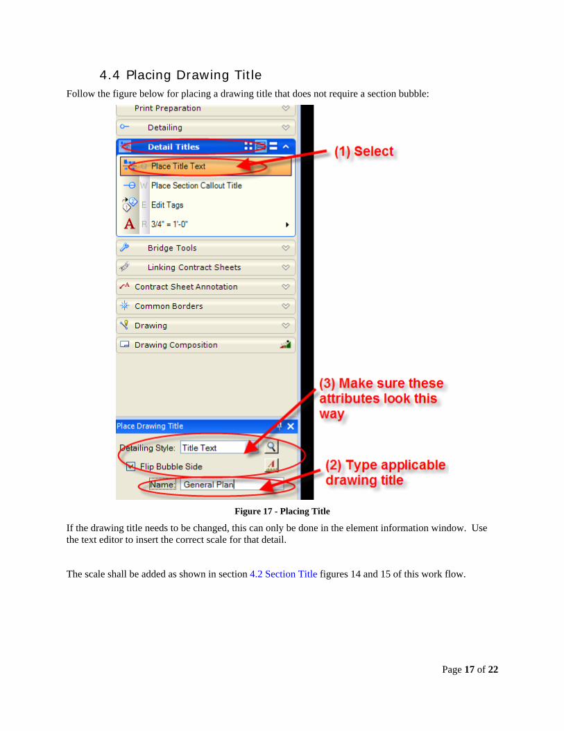
4.4 Placing Drawing Title Follow the figure below for placing a drawing title that does not require a section bubble:
Figure 17 - Placing Title
If the drawing title needs to be changed, this can only be done in the element information window. Use the text editor to insert the correct scale for that detail.
The scale shall be added as shown in section 4.2 Section Title figures 14 and 15 of this work flow.
Page 17 of 22

Page 18 of 22
Section 5 Linking Detail and Section Callouts to Drawing Titles
5.1 Linking the Section/Detail Callout and Section Title From the Same Contract Sheet
Follow the figures below linking the section callout and section title:
Figure 18 - Add Link to Element

Next identify element:
Figure 19 - Selecting Element to Link
The section callout will not update automatically, select the all fields icon as shown below to apply the update:
Figure 20 - Updating Section Callouts and Drawing Titles
The drawing titles and section callouts will update automatically when you reopen a drawing.
Page 19 of 22
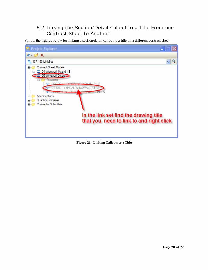
5.2 Linking the Section/Detail Callout to a Title From one Contract Sheet to Another
Follow the figures below for linking a section/detail callout to a title on a different contract sheet.
Figure 21 - Linking Callouts to a Title
Page 20 of 22

Figure 22 - Adding Link to Element
Figure 23 - Linking Element
Page 21 of 22

Figure 24 - Updating Callouts
Page 22 of 22


![A Practical Guide for Using MicroStation V8i SS2[1]](https://static.fdocuments.net/doc/165x107/55cf98d0550346d03399d256/a-practical-guide-for-using-microstation-v8i-ss21.jpg)