Using Microscopy to Help with the Understanding of ... · Degradation Mechanisms Observed in...
34
Journal of Materials Science and Engineering B 7 (9-10) (2017) 187-220 doi: 10.17265/2161-6221/2017.9-10.002 Using Microscopy to Help with the Understanding of Degradation Mechanisms Observed in Materials of Pressurized Water Reactors Laurent Legras 1 , Alexandre Volgin 1,2 , Bertrand Radiguet 2 , Philippe Pareige 2 , Cedric Pokor 1 , Brigitte Décamps 3 , Thierry Couvant 1 , Nicolas Huin 1,4 and Romain Soulas 1,5 1. EDF R&D-EDF Lab Les Renardières, Moret sur Loing cedex 77818, France 2. GPM Rouen, Avenue de l'Université, Saint-Étienne-du-Rouvray 76800, France 3. CSNSM IN2P3, Université de Paris Sud, Orsay 91400, France 4. Institut PPrime Université de Poitiers, ISAE-ENSMA, UPR 3346 BP 30179 F86962 Futuroscope Chasseneuil, France 5. INP Grenoble, SIMAP, Saint-Martin-d'Hères 38402, France Abstract: Even if temperature, pressure and chemistry of the cooling water are not very high and aggressive, materials used in PWRs (Pressurized Water Reactors) are exposed to different degradation mechanisms. One of the main goals of the research programs in this field is to develop physical model of the mechanisms down to the atomic scale. Such approach needs a clear description and understanding of the degradation mechanisms at the same small scale. This paper illustrates the benefits of different microscopies and of their last improvements up to the promising possibilities of monochromated and aberrations corrected TEM/STEM. A specific focus is placed on four different degradation mechanisms observed in austenitic stainless steel: irradiation ageing, corrosion fatigue, stress corrosion cracking and corrosion. Key words: PWR, TEM, APT, 3D SEM, irradiation ageing, corrosion fatigue, stress corrosion cracking, corrosion. Even if temperature, pressure and chemistry of the 1 cooling water are not very high and aggressive, materials used in PWRs (Pressurized Water Reactors) are exposed to different degradation mechanisms. Some of these materials (internal components, vessel...) are also exposed to irradiation, leading to complex degradation such as IASCC (Irradiation Assisted Stress Corrosion Cracking). One of the main goals of the research programs in this field is to develop physical model of the mechanisms down to the atomic scale. Such approach needs a clear description and understanding of the degradation mechanisms at the same small scale. Corresponding author: Laurent Legras, Dr., research fields: material science, transmission electron microscopy, metallurgy, degradation mechanisms observed in materials of pressurized water reactors: corrosion, stress corrosion cracking, irradiation assisted stress corrosion cracking and fatigue corrosion. This paper illustrates the benefits of different microscopies and of their last improvements (TEM—Transmission Electron Microscopy, APT—Atom Probe Tomography, dual beam microscopes, EBSD—Electron Back Scattered Diffraction...) up to the very new promising possibilities of monochromated and aberrations corrected TEM. A specific focus will be placed on four different degradation mechanisms observed in austenitic stainless steel: irradiation ageing, corrosion fatigue, stress corrosion cracking and corrosion. (1) Irradiation ageing The internal structures of the PWR vessel are made in austenitic stainless steel. Irradiation continuously induces point defects which can recombine together, and be eliminated on sinks or aggregated. Interstitials aggregate forming disk shape i.e. dislocations loops or D DAVID PUBLISHING
Transcript of Using Microscopy to Help with the Understanding of ... · Degradation Mechanisms Observed in...

Journal of Materials Science and Engineering B 7 (9-10) (2017) 187-220 doi: 10.17265/2161-6221/2017.9-10.002
Using Microscopy to Help with the Understanding of
Degradation Mechanisms Observed in Materials of
Pressurized Water Reactors
Laurent Legras1, Alexandre Volgin1,2, Bertrand Radiguet2, Philippe Pareige2, Cedric Pokor1, Brigitte Décamps3,
Thierry Couvant1, Nicolas Huin1,4 and Romain Soulas1,5
1. EDF R&D-EDF Lab Les Renardières, Moret sur Loing cedex 77818, France
2. GPM Rouen, Avenue de l'Université, Saint-Étienne-du-Rouvray 76800, France
3. CSNSM IN2P3, Université de Paris Sud, Orsay 91400, France
4. Institut PPrime Université de Poitiers, ISAE-ENSMA, UPR 3346 BP 30179 F86962 Futuroscope Chasseneuil, France
5. INP Grenoble, SIMAP, Saint-Martin-d'Hères 38402, France
Abstract: Even if temperature, pressure and chemistry of the cooling water are not very high and aggressive, materials used in PWRs (Pressurized Water Reactors) are exposed to different degradation mechanisms. One of the main goals of the research programs in this field is to develop physical model of the mechanisms down to the atomic scale. Such approach needs a clear description and understanding of the degradation mechanisms at the same small scale. This paper illustrates the benefits of different microscopies and of their last improvements up to the promising possibilities of monochromated and aberrations corrected TEM/STEM. A specific focus is placed on four different degradation mechanisms observed in austenitic stainless steel: irradiation ageing, corrosion fatigue, stress corrosion cracking and corrosion.
Key words: PWR, TEM, APT, 3D SEM, irradiation ageing, corrosion fatigue, stress corrosion cracking, corrosion.
Even if temperature, pressure and chemistry of the 1 cooling water are not very high and aggressive,
materials used in PWRs (Pressurized Water Reactors)
are exposed to different degradation mechanisms.
Some of these materials (internal components,
vessel...) are also exposed to irradiation, leading to
complex degradation such as IASCC (Irradiation
Assisted Stress Corrosion Cracking). One of the main
goals of the research programs in this field is to
develop physical model of the mechanisms down to
the atomic scale. Such approach needs a clear
description and understanding of the degradation
mechanisms at the same small scale.
Corresponding author: Laurent Legras, Dr., research fields:
material science, transmission electron microscopy, metallurgy, degradation mechanisms observed in materials of pressurized water reactors: corrosion, stress corrosion cracking, irradiation assisted stress corrosion cracking and fatigue corrosion.
This paper illustrates the benefits of different
microscopies and of their last improvements
(TEM—Transmission Electron Microscopy,
APT—Atom Probe Tomography, dual beam
microscopes, EBSD—Electron Back Scattered
Diffraction...) up to the very new promising
possibilities of monochromated and aberrations
corrected TEM. A specific focus will be placed on
four different degradation mechanisms observed in
austenitic stainless steel: irradiation ageing, corrosion
fatigue, stress corrosion cracking and corrosion.
(1) Irradiation ageing
The internal structures of the PWR vessel are made
in austenitic stainless steel. Irradiation continuously
induces point defects which can recombine together,
and be eliminated on sinks or aggregated. Interstitials
aggregate forming disk shape i.e. dislocations loops or
D DAVID PUBLISHING

Using Microscopy to Help with the Understanding of Degradation Mechanisms Observed in Materials of Pressurized Water Reactors
188
segregate on grain boundaries. Vacancies could lead
to the formation of cavities or bubbles when
combining with gas atoms such as H or He. In
addition the coupling between point defect fluxes
towards sinks and solute atom diffusion can lead to
solute aggregation at sinks. Kinetics studies and
quantification of these phenomena are performed
using TEM and APT and are used as key data for the
understanding of mechanisms and for modelling
lifetime extension of actual PWRs. Ni and Si
segregations and Cr depletion on dislocation loops
were recently showed owing to new developments of
APT leading to better understanding of their
hardening effect.
(2) SCC (stress corrosion cracking)
Strain gradients and preferential sites of
intergranular SCC initiation have recently appeared to
be correlated. Combining complex strain on specimen
pre-mapped and the possibility of extracting TEM thin
foils on a precise location using dual beam offer a
promising possibility to understand fracture
mechanisms ahead of the crack tips. Current TEM
studies on such specimen are trying to understand the
stability of oxides films at the cracks tips as a function
of crystallographic orientation and strain. The very
first results exhibited that diffusion of Cr and Fe is
very fast at grain boundaries and accelerated by strain.
What is more the higher the strain was, the higher the
oxide penetration was, and thus the more SCC
degradation was favored.
(3) Corrosion fatigue
Specific areas of primary circuit in PWRs can be
affected by thermal fatigue. Recent TEM studies on
fatigue crack tips clearly showed that the effect of
oxidation is combined with the fatigue loading and
thus it has to be taken into account. 3D images with
dual beam coupled with TEM observations clearly
showed that oxide penetration along shear bands is
about 1.5 higher than in the matrix. Another result is
that oxide thickness measured after cyclic loading is
more than ten times higher than after a 2,000 h
monocyclic loading in SCC test.
(4) Corrosion
SCC corrosion fatigue and corrosion behaviour are
controlled by the properties of the oxide films. The
well known duplex structure of the oxides is still
suffering from uncertainties such as the very first step
of their growth and their crystallographic structure.
These two questions are currently under investigation
up to the atomic scale on very short exposure time.
HR(S)TEM (High Resolution (Scanning)
Transmission Electron Microscopy) and ASTAR
software clearly showed that the inner chromium rich
oxide is a (FeCr)3O4 spinel oxide growing with a
cube/cube epitaxial crystallographic relationship with
the base metal. HREELS (High Resolution Electron
Energy Loss Spectroscopy) also clearly showed the
possibility of quantifying the Fe2+/Fe3+ ratio in the
oxide and thus to get new informations on the passive
property of the Cr rich film layer depending if this
spinel is normal, intermediate or inversed ones.
1. General Introduction
Materials used in PWR are exposed to different
degradation mechanisms even if temperature, pressure
and chemistry of the cooling water are not very high
and aggressive. Some of the core components (internal
components, vessel...) are also exposed to irradiation
leading to complex ageing mechanisms such as
IGASCC (Irradiation Assisted Stress Corrosion
Cracking). This degradation involves a coupling
between irradiation ageing, external stress and
corrosion. SCC (Stress Corrosion Cracking) seems to
be generic and has a large impact on safety because it
occurs in the second containment barrier. Thermal
fatigue (and the possibility of a coupling effect with
PWR environment) is considered as a potential
degradation mechanism inside specific areas (surge
line, steam generator feedwater lines, hot and cold
water mixing areas…). Corrosion related degradation
of PWR materials has a significant impact on plant
availability and maintenance costs.

Using Microscopy to Help with the Understanding of Degradation Mechanisms Observed in Materials of Pressurized Water Reactors
189
One of the main goals of the research programs
launched in these fields is to develop physical
modeling of the mechanism involved. Such approach
needs a clear description and understanding of the
ageing mechanism at the same scale that the modeling
one and thus various characterization techniques: (1)
Irradiation ageing modeling needs to know the
macroscopic evolution of irradiation defects but also
their exact chemistry and nature at sub nanometer
scale. (2) Modeling of SCC and of thermal fatigue
needs a good knowledge of the strain heterogeneity as
a function of microstructure gradient from the
component down to the grain scale but also a fine
description of the local composition, thickness and
structure at nanometer scale. (3) Properties of oxide
films are a crucial point which needs macroscopic
kinetic measurement but also a good knowledge of
their chemistry, structure and growth mechanism from
the very beginning of the oxidation process and thus
down to the atomic scale.
Since all these degradation mechanisms are
affecting numerous materials (stainless steels, nickel
based alloys, zirconium alloys...) we will illustrate the
benefit of some characterization techniques up to the
very promising possibilities of monochromated and
aberrations corrected HR(S)TEM in some undergoing
research programs on degradations mechanism
affecting austenitic stainless steels.
2. Irradiation Ageing of 316 L Austenitic Stainless Steel
2.1 State of the Art
The internal structures of PWR located close to the
reactor core are used to support the fuel assemblies, to
maintain the alignment between assemblies and the
control rods and to channel the primary water (Fig. 1).
In general these internal structures consist of baffle
plates in Solution Annealed 304 stainless steel and
baffle bolts in Cold Worked 316 stainless steel. These
components undergo a large neutron flux (up to 100
displacements per atom—dpa) at temperatures
between 280 and 380 °C. As a result, the material
exhibits a substantial increase in yield stress (Fig. 2),
reduction in ductility, swelling loss of corrosion
resistance which may be damaging to the proper
operation of the reactor [1-7]. For instance cracks
were observed in bolts (Fig. 3) [8-11]. These cracks
usually attributed to IASCC (Irradiation Assisted
Stress Corrosion Cracking), can be seen as a
consequence of the evolution of plasticity in these
materials loaded in a corrosive medium, together with
possible evolutions of grain boundary chemistry (due
to RIS—Radiation Induced Segregation) [12].
Fig. 1 (a) Schematic drawing of a PWR vessel and (b) schematic drawing of internal structures.
(a) (b)

Using Microscopy to Help with the Understanding of Degradation Mechanisms Observed in Materials of Pressurized Water Reactors
190
Fig. 2 Hardening as a function of neutron irradiation dose on a cold worked 316 stainless steel [2].
50 μm
(a) (b)
Fig. 3 (a) Example of a crack observed of an internal bold; (b) SEM image showing the intergranular propagation of the crack.
Since evolutions of the macroscopic properties are
related to the microstructure ones, understanding
microstructure evolution under irradiation is essential
to predict lifetime of internals. A large number of
studies were focused on the characterization of the
microstructure under irradiation. On one hand, it was
shown that RIS at GBs (grain boundaries) can
contribute to the loss of corrosion resistance and could
be implicated in the IASCC [13-16]. Indeed, under
irradiation, a permanent flux of PD (point defects) is
produced towards sinks like GB. As coupling is
created between PD and solutes fluxes, it results in a
Cr depletion and an enrichment in Ni at GB (Fig. 4a).
On the other hand, TEM (transmission electron
microscopy) observations (Figs. 4b and 4c) have
shown that radiation-hardening could be caused by the
formation of a high number density of Frank loops
and PD clusters [17-21]. However, to ensure that the
yield stress evolution is only due to the Frank loops
formation, a chemical characterization of the
microstructure was performed. γ' precipitation [20, 22]
or Ni-Si enrichment at Frank loops [23] observations
using conventional TEM are reported in the literature.
This was completed more recently by A. Etienne
owing to the development of the LATAP (Laser
Assisted Tomographic Atom Probe) at the GPM

Using Microscopy to Help with the Understanding of Degradation Mechanisms Observed in Materials of Pressurized Water Reactors
191
(Groupe de Physique des Matériaux) in the University
of Rouen (Fig. 4d [24]). The LATAP allows the
analysis of such brittle materials which were very
difficult with conventional TAP (using electric pulse).
After neutron irradiation, she observed heterogeneous
distribution of solute atoms, and the presence of two
kinds of features, Si atmospheres and Ni-Si enriched
clusters were shown in Ref. [24]. The comparison
between LATAP analysis and TEM investigation of Fe
irradiated samples suggested that Ni-Si rich clusters
Fig. 4 Examples of images and chemical analysis performed on irradiated 316 L. (a) Cavities and γ' precipitation [2].
Fig. 4 Examples of images and chemical analysis performed on irradiated 316 L. (b) Frank loops [2].

Using Microscopy to Help with the Understanding of Degradation Mechanisms Observed in Materials of Pressurized Water Reactors
192
Fig. 4 Examples of images and chemical analysis performed on irradiated 316 L. (c) EDXS line scan analysis using FEG STEM on a grain boundary of an irradiated 316 L [16].
Fe
Cr
Ni
60nm
Fig. 4 Examples of images and chemical analysis performed on irradiated 316 L. (d) 3D reconstruction of a volume of 316 L irradiated by neutron showing Ni-Si clusters [24].

Using Microscopy to Help with the Understanding of Degradation Mechanisms Observed in Materials of Pressurized Water Reactors
193
could be formed by induced degradation on
dislocation loops [25, 26]. But at that time, this
formation mechanism still needed to be more detailed.
The aim of this part is to illustrate the benefit of
coupling TEM observations and APT analysis rather
than explaining the clustering mechanism observed
under irradiation. This is done through presenting
some results obtained during the PhD work of A.
Volgin [27] and presented at TMS 2012 conference.
This PhD work is performed under the European
project PERFORM 60.
2.2 Results & Discussion
Specimens were extracted from a 5% cold worked
316 SS annealed 10 minutes at 1,100 °C and from a
ternary hot rolled FeCrNi alloy annealed 1 h at
1,100 °C. After annealing both samples were water
quenched. The bulk compositions of these alloys are
given in Table 1. Then 5 MeV Ni++ irradiations were
performed at Orsay JANNuS platform at 450 °C. The
temperature shift with respect to PWR conditions is
necessary for compensating flux effects [28-32]. The
cumulative dose at the depth where samples are
prepared is 5 dpa. TEM observations were done at
EDF R&D on a TECNAI G2 20F. Irradiated atom
probe samples were prepared from 3 millimeter disks
using dual beam at GPM in the University of Rouen.
Chemical characterization at the atomic scale was
performed using the Cameca LAWATAP (Wide
Angle LATAP) at GPM. The principle of this
instrument is described in Refs. [33, 34]. Analyses
were performed at 50 K, using femtosecond laser
pulses with a wavelength equal to 330 nm and a pulse
energy resulting in the same effect as that of an
electric pulse equal to 20%-25% of the standing
voltage.
The microstructure of the irradiated specimens
consists in interstitial Frank and perfect loops (Fig. 5a),
in vacancy clusters in the form of small voids (Fig. 5b)
and Stacking Fault Tetrahedra (Fig. 5c). These
observations were also done to measure the number
density and the size of these features and thus, to get
an estimation of their quantitative hardening effect.
Finally, from conventional bright and dark field TEM
observations, no clear evidence of precipitation is
observed (no chemical analyses using TEM were
performed). To clarify this point, LAWATAP
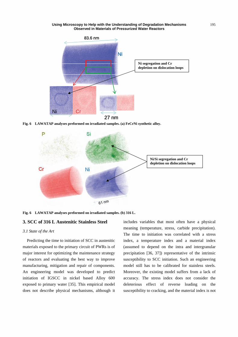
analyses were performed on irradiated samples. These
analyses clearly evidence Ni, Si segregation on
dislocation loops whereas Cr depletion is observed at
the same times (Fig. 6). Some Ni, Si enriched clusters
that are also pointed out. Because of their small size
and density, all these objects would be very difficult
to be detected using EDX or EELS analyses in TEM.
It is certainly more difficult, if not impossible, to
quantify precisely the amount of the Ni, Si enrichment
and Cr depletion using such chemical analysis in TEM.
Thus, the exact nature of the objects on which
segregation and depletion are observed is done using a
comparison between TEM images obtained from one
side and from APT analysis on the other side. Even if
the link can be made comparing the size, density,
morphology of these objects, further HAADF
HRSTEM images and EELS analyses using probe
corrected and monochromated TEM will be performed
to try to fill this gap. In addition, the same APT thin
needles will be analyzed by conventional TEM
(crystal defects) HAADF HRSTEM and APT.
The authors acknowledge Orsay JANNuS Team for
performing irradiations.
Table 1 Bulk compositions of ternary model alloy and 316 austenitic stainless steel. Concentrations are in wt. %. Balance is iron.
Alloy\Element (%wt) Cr Ni Si C N Mo Cu P S
316 L 17.60 12.00 0.59 0.028 0.08 2.39 0.066 0.01 0.01
FeNiCr 1818.27 12.40 - 0.008 - - - - 0.003
Using Microscopy to Help with the Understanding of Degradation Mechanisms Observed in Materials of Pressurized Water Reactors
194
Fig. 5 Example of defects observed in irradiated 316 L and FeNiCr alloy. (a) Example of 1 from 4 Frank loop families.
Fig. 5 Example of defects observed in irradiated 316 L and FeNiCr alloy. (b) Cavities: Underfocused bright field TEM image.
Fig. 5 Example of defects observed in irradiated 316 L and FeNiCr alloy. (c) Example of Stacking Fault Tetrahedra.
20 nm
Using Microscopy to Help with the Understanding of Degradation Mechanisms Observed in Materials of Pressurized Water Reactors
195
Fig. 6 LAWATAP analyses preformed on irradiated samples. (a) FeCrNi synthetic alloy.
Fig. 6 LAWATAP analyses preformed on irradiated samples. (b) 316 L.
3. SCC of 316 L Austenitic Stainless Steel
3.1 State of the Art
Predicting the time to initiation of SCC in austenitic
materials exposed to the primary circuit of PWRs is of
major interest for optimizing the maintenance strategy
of reactors and evaluating the best way to improve
manufacturing, mitigation and repair of components.
An engineering model was developed to predict
initiation of IGSCC in nickel based Alloy 600
exposed to primary water [35]. This empirical model
does not describe physical mechanisms, although it
includes variables that most often have a physical
meaning (temperature, stress, carbide precipitation).
The time to initiation was correlated with a stress
index, a temperature index and a material index
(assumed to depend on the intra and intergranular
precipitation [36, 37]) representative of the intrinsic
susceptibility to SCC initiation. Such an engineering
model still has to be calibrated for stainless steels.
Moreover, the existing model suffers from a lack of
accuracy. The stress index does not consider the
deleterious effect of reverse loading on the
susceptibility to cracking, and the material index is not
Ni
83.6 nm
Ni Cr27 nm
NiNi
83.6 nm
Ni Cr27 nm
Ni segregation and Cr depletion on dislocation loops
Ni/Si segregation and Cr depletion on dislocation loops

Using Microscopy to Help with the Understanding of Degradation Mechanisms Observed in Materials of Pressurized Water Reactors
196
parameterized by the limiting microstructural factors
driving corrosion (local material chemistry, transport
of oxygen and ions within the oxide and the metal).
Due to a lack of understanding, the calibration of the
model is not accurate.
Field experience highlighted the deleterious effect
of strain hardening on SCC (Fig. 7) in nominal
primary water. Pressurizer heaters [38, 39], made of
stainless steels, and steam generator divider plates
[40-42], made of rolled Alloy 600 were both affected
by SCC. In each case, the level of deformation and
heterogeneity at a macroscale, captured by micro
hardness or neutron diffraction, was believed to play a
major role in the occurrence, location, and kinetics of
SCC [43, 44]. At a lower scale of strain localization,
scanning and transmission electron microcopy
observations suggested possible deleterious local
interaction between oxidation and mechanical fields
[45]. Fig. 8 shows precursors to IGSCC aligned with
emerging shear bands at the surface of 304 L exposed
to a primary environment, while Fig. 9 exhibits the
presence of shear bands intersecting a grain boundary
where SCC propagates.
Understanding and quantification of interactions
between localized deformation in materials and EAC
(environmental-assisted cracking) could play an
important role in maintaining the integrity of LWR
components. Thus, a detailed understanding of strain
Fig. 7 IGSCC initiation at the surface of a heater of pressurizer.
Fig. 8 SEM image of IGSCC initiation sites lined with slip bands intersecting the grain boundary on 304 L in a nominal hydrogenated primary PWR environment at 360 °C [33].
30 µm

Using Microscopy to Help with the Understanding of Degradation Mechanisms Observed in Materials of Pressurized Water Reactors
197
Fig. 9 TEM image of intergranular propagation assisted by localized deformation. Crack growth test in a PWR environment on a 40% cold rolled 304 L [33].
Fig. 10 Back face of the cross specimen.
localization during plastic deformation and of the
underlying mechanisms is important for the
manufacture, design, and repair of materials exposed
to the environment of the PWRs primary circuit.
3.2 Results and Discussion
The deleterious effect of cross tests on
susceptibility of 304 L to IGSCC in PWR
environments (1,000 ppm B, 2 ppm Li, 20 cc H2) at
360 °C was shown in previous studies [46]. This result
has been interpreted by the authors to be a
consequence of the strain localization induced by
orthogonal strain paths as defined by Schmitt [47].
Cross tests are used to promote strain localization. The
cross specimen (Fig. 10) was specially designed. Only
one face is perfectly polished for material
characterization, and local strain evaluation.
Grids which were deposed at LPMTM2 (Paris XIII
University, Galileo Institute) by electronic micro
lithography, at the center of the specimens before
testing to allow quantification of superficial strain
localization after pre-strain hardening in air and
followed by deformation in the primary PWR
environment at 360 °C. Gridline images were
collected before and after each step of deformation
2 Laboratoire des Propriétés Mécaniques et Thermodynamiques des Matériaux (Villetaneuse, France).
Prior strain (air) axis X
Axis Y
for testing in primary water
Shear Bands

Using Microscopy to Help with the Understanding of Degradation Mechanisms Observed in Materials of Pressurized Water Reactors
198
using SEM (scanning electron microscopy).
Comparison of the grid before and after (Fig. 11)
deformation revealed the material superficial
displacement field [48].
Tools were developed (Matlab) in order to do cross
correlations between microstructural parameters such
as grain orientation and grain boundary as collected by
EBSD and mechanical fields based on DIC of strain
and strain path. Using this method, distribution can be
evaluated and compared and the local deformation
path known. Thin foils with well known
crystallographic orientation, strain level, and strain
path were extracted with Dual Beam. Then, the effect
of the local strain and path influence on the oxide
growth and on cracks initiation and growth were
studied by TEM. Figs. 12 and 13 show that the oxides
Fig. 11 (a) Grid before deformation. Initial mesh size = 5 µm.
Fig. 11 (b) Grid after deformation in ambient air. Initial mesh size = 5 µm.

Using Microscopy to Help with the Understanding of Degradation Mechanisms Observed in Materials of Pressurized Water Reactors
199
STEM HAADF Image obtained on a cross-section 316 L site 1
EDX line scan profile 1
EDX line scan profile 2
EDX line scan profile 3
Fig. 12 STEM HAADF Image and EDX line scan profile cross the oxides layers (at surface and in intergranular crack) on a cross section of 316 L site 1 (Prior-Exx = 0, second Eyy = 0.03, t = 720 h, pH320 °C = 7.2).
1,5µm
EDX profile 1 EDX profile 2
EDX profile 3
Using Microscopy to Help with the Understanding of Degradation Mechanisms Observed in Materials of Pressurized Water Reactors
200
ZLP image O filtered image Cr filtered image Fe filtered image Ni filtered image
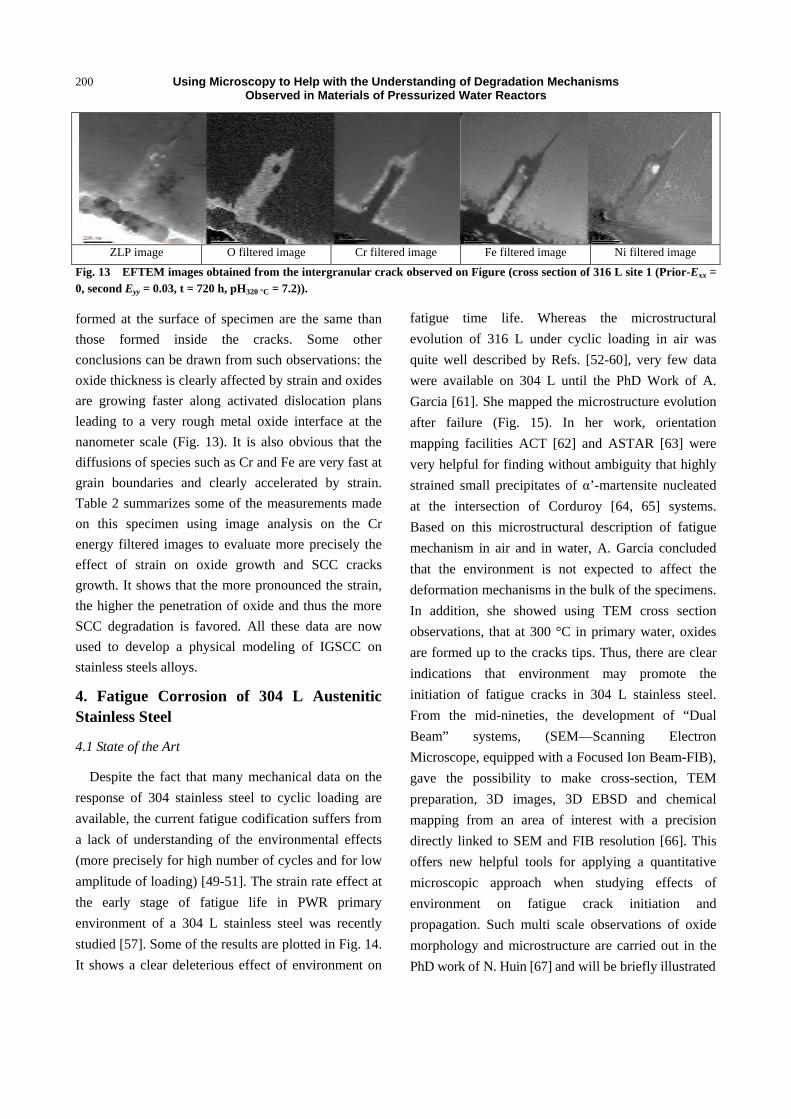
Fig. 13 EFTEM images obtained from the intergranular crack observed on Figure (cross section of 316 L site 1 (Prior-Exx = 0, second Eyy = 0.03, t = 720 h, pH320 °C = 7.2)).
formed at the surface of specimen are the same than
those formed inside the cracks. Some other
conclusions can be drawn from such observations: the
oxide thickness is clearly affected by strain and oxides
are growing faster along activated dislocation plans
leading to a very rough metal oxide interface at the
nanometer scale (Fig. 13). It is also obvious that the
diffusions of species such as Cr and Fe are very fast at
grain boundaries and clearly accelerated by strain.
Table 2 summarizes some of the measurements made
on this specimen using image analysis on the Cr
energy filtered images to evaluate more precisely the
effect of strain on oxide growth and SCC cracks
growth. It shows that the more pronounced the strain,
the higher the penetration of oxide and thus the more
SCC degradation is favored. All these data are now
used to develop a physical modeling of IGSCC on
stainless steels alloys.
4. Fatigue Corrosion of 304 L Austenitic Stainless Steel
4.1 State of the Art
Despite the fact that many mechanical data on the
response of 304 stainless steel to cyclic loading are
available, the current fatigue codification suffers from
a lack of understanding of the environmental effects
(more precisely for high number of cycles and for low
amplitude of loading) [49-51]. The strain rate effect at
the early stage of fatigue life in PWR primary
environment of a 304 L stainless steel was recently
studied [57]. Some of the results are plotted in Fig. 14.
It shows a clear deleterious effect of environment on
fatigue time life. Whereas the microstructural
evolution of 316 L under cyclic loading in air was
quite well described by Refs. [52-60], very few data
were available on 304 L until the PhD Work of A.
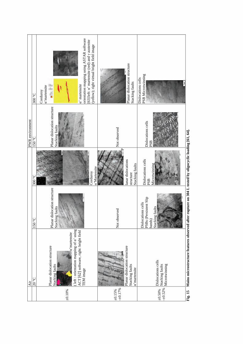
Garcia [61]. She mapped the microstructure evolution
after failure (Fig. 15). In her work, orientation
mapping facilities ACT [62] and ASTAR [63] were
very helpful for finding without ambiguity that highly
strained small precipitates of α’-martensite nucleated
at the intersection of Corduroy [64, 65] systems.
Based on this microstructural description of fatigue
mechanism in air and in water, A. Garcia concluded
that the environment is not expected to affect the
deformation mechanisms in the bulk of the specimens.
In addition, she showed using TEM cross section
observations, that at 300 °C in primary water, oxides
are formed up to the cracks tips. Thus, there are clear
indications that environment may promote the
initiation of fatigue cracks in 304 L stainless steel.
From the mid-nineties, the development of “Dual
Beam” systems, (SEM—Scanning Electron
Microscope, equipped with a Focused Ion Beam-FIB),
gave the possibility to make cross-section, TEM
preparation, 3D images, 3D EBSD and chemical
mapping from an area of interest with a precision
directly linked to SEM and FIB resolution [66]. This
offers new helpful tools for applying a quantitative
microscopic approach when studying effects of
environment on fatigue crack initiation and
propagation. Such multi scale observations of oxide
morphology and microstructure are carried out in the
PhD work of N. Huin [67] and will be briefly illustrated

Using Microscopy to Help with the Understanding of Degradation Mechanisms Observed in Materials of Pressurized Water Reactors
201
Table 1 Analysis of 3 cracks initiated at the surface of the 316 L specimen, 720 h, pH320 °C = 7.2).
Crack Flank Local strain in the
sample
Crack length (nm)
Oxide at the crack tip (nm)
Affected grain boundary length (nm)
Analyzed length (nm)
Cr-rich inner oxide penetration (nm)
Prior Exx Second Eyy Average Median Min. Max. SD
1 Left 0.05 0.05
899 59 170 786 88 89 48 119 16
Right 0.08 0.10 619 76 83 24 125 28
2 Left 0.00 0.02
548 136 136 304 67 66 50 89 9
Right 0.00 0.02 322 66 64 56 82 7
3 Left 0.1 0.01
317 110 125 123 43 43 33 52 5
Right 0.1 0.01 143 36 38 16 47 7
0
0,1
0,2
0,3
0,4
0,5
0,6
1,E+02 1,E+03 1,E+04 1,E+05 1,E+06 1,E+07
To
tal s
trai
n a
mp
litu
de
(%)
Fatigue life (N)
Material Environment Temperature Strain rate
Symbol (°C) (%/s)
As-received PWR
300 °C
0.4
0.004
AIR 0.4
Fig. 14 Environmental effect on 304 L fatigue life at 300 °C [49].
in the following.
4.2 Results and Discussion
Initial surface of materials plays an important role
in fatigue crack initiation. Preferential cracks
initiations are localized where local strains induced by
cycling are high. PSBs (Persistent Slip Bands) create a
surface roughness composed of intrusion and
extrusion (Fig. 16) which are precursors of material
damaging [68]. Crystallographic orientation of each
grain plays an important role in the process of
emerging PSB. Indeed, during a fatigue test, some
grains underwent low plastic strains while others were
strongly strained with mainly only one slip system
activated [69]. The Schmid factor (giving the
orientation of a gliding plane and its
direction/macroscopic applied stress) can be used to
quantify the initiation probability of fatigue cracks. A
statistic evaluation on a 316 L stainless steel at 20 °C
loaded at ∆εp/2 = 2×10⁻³, with a Schmid factor calculated
A
ir
PW
R e
nvir
onm
ent
20
°C
15
0 °C
30
0 °C
15
0 °C
30
0 °C
±0.1
0%
Plan
ar d
islo
cati
on s
truc
ture
S
tack
ing
faul
ts
α’m
arte
nsite
( le
ft :
orie
ntat
ion
map
ping
of α’
usi
ng
AC
T [6
2] s
oftw
are,
rig
ht: b
righ
t fie
ld
TE
M im
age
Pla
nar
disl
ocat
ion
stru
ctur
e S
tack
ing
faul
ts
C
ordu
roy
α’M
arte
nsit
e
Plan
ar d
islo
cati
on s
truc
ture
S
tack
ing
faul
ts
Cor
duro
y α’
mar
tens
ite
α’ m
arte
nsit
e
orie
ntat
ion
map
ping
usi
ng A
ST
AR
sof
twar
e [6
3] le
ft: α
’ m
arte
nsit
e (r
ed)
and γ
aust
enit
e (y
ello
w);
rig
ht v
irtu
al b
righ
t fie
ld im
age
±0.1
5%
-±0.
17%
Pl
anar
dis
loca
tion
str
uctu
re
Sta
ckin
g fa
ults
α’
mar
tens
ite
Not
obs
erve
d P
lana
r di
sloc
atio
ns
stru
ctur
e S
tack
ing
faul
ts
Not
obs
erve
d
Pl
anar
dis
loca
tion
str
uctu
re
Sta
ckin
g fa
ults
±0.5
0%
-±0.
52%
Dis
loca
tion
s ce
lls
Sta
ckin
g fa
ults
M
icro
twin
ning
Dis
loca
tion
s ce
lls
PS
Bs
(Per
sist
ent S
lip
band
s)
Sta
ckin
g fa
ults
Dis
loca
tion
s ce
lls
PSB
M
icro
twin
ning
Dis
loca
tion
s ce
lls
PSB
Dis
loca
tion
s ce
lls
PS
B M
icro
twin
ning
Fig
. 15
Mai
ns m
icro
stru
ctur
e fe
atur
es o
bser
ved
afte
r ru
ptu
re o
n 3
04 L
tes
ted
by
olig
ocyc
lic
load
ing
[61,
64]
.
Using Microscopy to Help with the Understanding of degradation mechanisms Observed in Materials of Pressurized Water Reactors
203
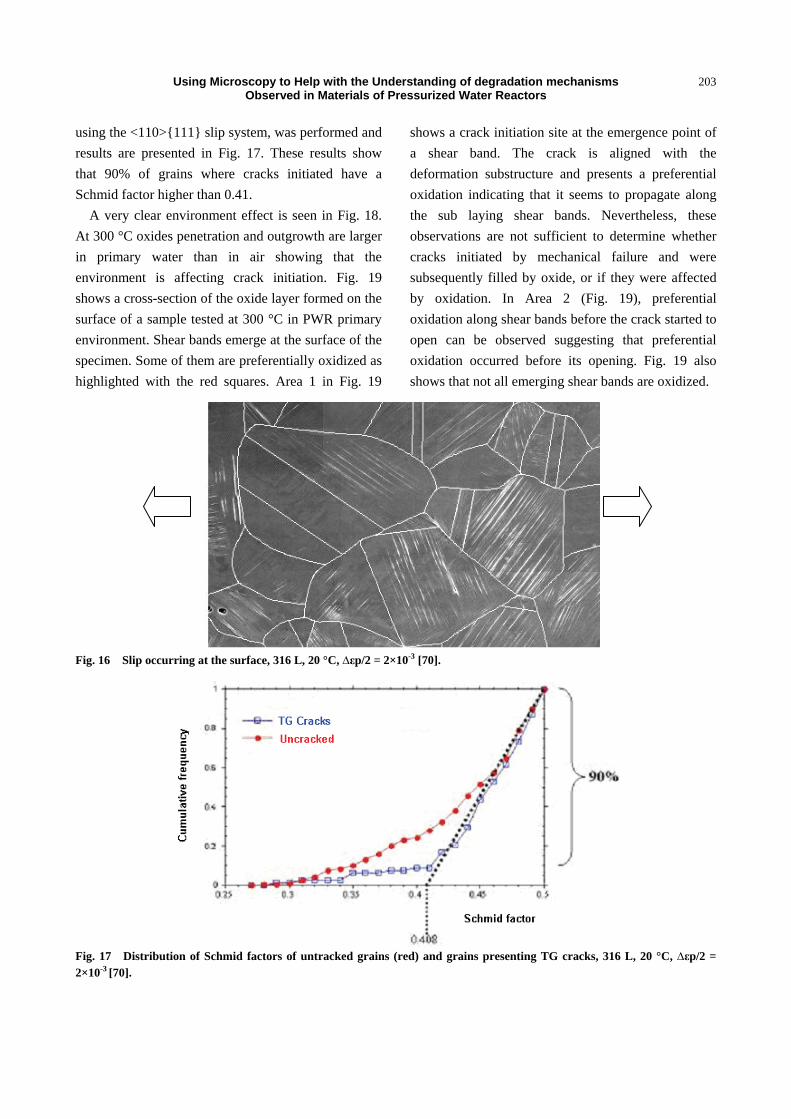
using the <110>{111} slip system, was performed and
results are presented in Fig. 17. These results show
that 90% of grains where cracks initiated have a
Schmid factor higher than 0.41.
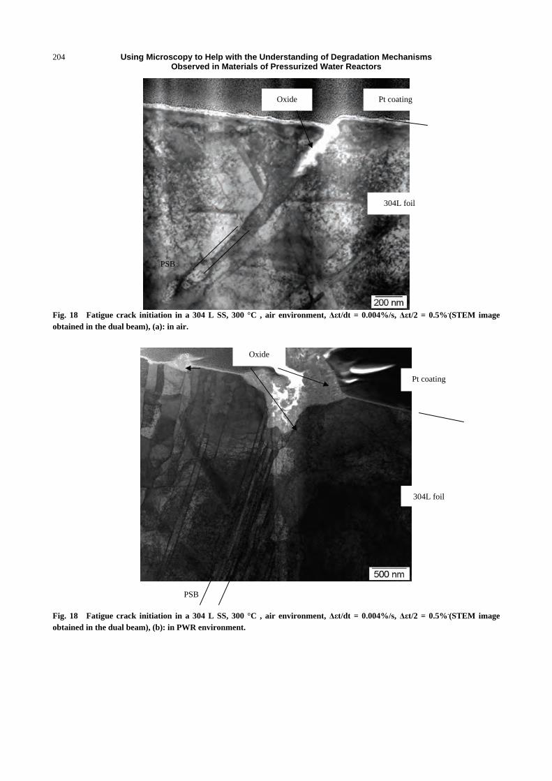
A very clear environment effect is seen in Fig. 18.
At 300 °C oxides penetration and outgrowth are larger
in primary water than in air showing that the
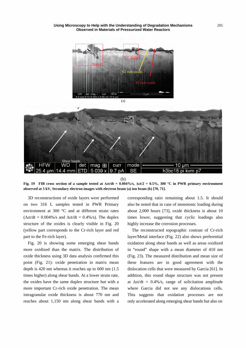
environment is affecting crack initiation. Fig. 19
shows a cross-section of the oxide layer formed on the
surface of a sample tested at 300 °C in PWR primary
environment. Shear bands emerge at the surface of the
specimen. Some of them are preferentially oxidized as
highlighted with the red squares. Area 1 in Fig. 19
shows a crack initiation site at the emergence point of
a shear band. The crack is aligned with the
deformation substructure and presents a preferential
oxidation indicating that it seems to propagate along
the sub laying shear bands. Nevertheless, these
observations are not sufficient to determine whether
cracks initiated by mechanical failure and were
subsequently filled by oxide, or if they were affected
by oxidation. In Area 2 (Fig. 19), preferential
oxidation along shear bands before the crack started to
open can be observed suggesting that preferential
oxidation occurred before its opening. Fig. 19 also
shows that not all emerging shear bands are oxidized.
Fig. 16 Slip occurring at the surface, 316 L, 20 °C, ∆εp/2 = 2×10⁻³ [70].
Fig. 17 Distribution of Schmid factors of untracked grains (red) and grains presenting TG cracks, 316 L, 20 °C, ∆εp/2 = 2×10⁻³ [70].
Using Microscopy to Help with the Understanding of Degradation Mechanisms Observed in Materials of Pressurized Water Reactors
204
Fig. 18 Fatigue crack initiation in a 304 L SS, 300 °C , air environment, Δεt/dt = 0.004%/s, Δεt/2 = 0.5%.(STEM image obtained in the dual beam), (a): in air.
Fig. 18 Fatigue crack initiation in a 304 L SS, 300 °C , air environment, Δεt/dt = 0.004%/s, Δεt/2 = 0.5%.(STEM image obtained in the dual beam), (b): in PWR environment.
Pt coating
304L foil
Oxide
PSB
PSB
Pt coating
304L foil
Oxide
Using Microscopy to Help with the Understanding of Degradation Mechanisms Observed in Materials of Pressurized Water Reactors
205
(a)
(b)
Fig. 19 FIB cross section of a sample tested at Δεt/dt = 0.004%/s, Δεt/2 = 0.5%, 300 °C in PWR primary environment observed at 5 kV, Secondary electron images with electron beam (a) ion beam (b) [70, 71].
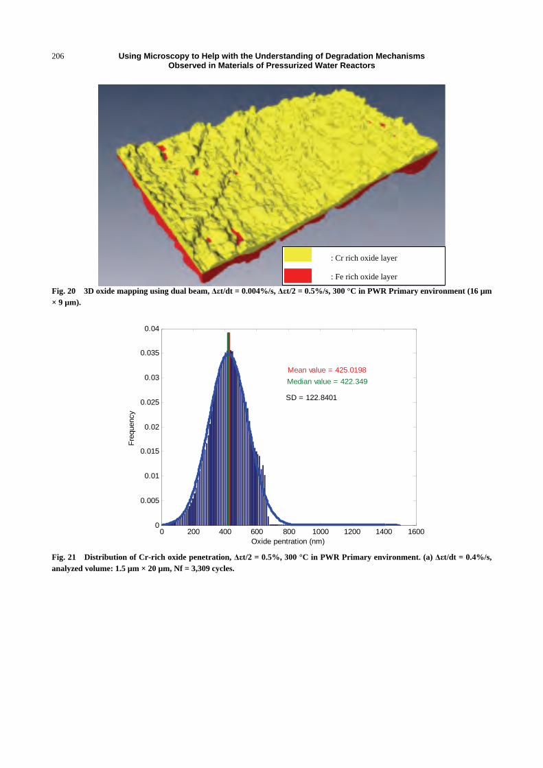
3D reconstructions of oxide layers were performed
on two 316 L samples tested in PWR Primary
environment at 300 °C and at different strain rates
(Δεt/dt = 0.004%/s and Δεt/dt = 0.4%/s). The duplex
structure of the oxides is clearly visible in Fig. 20
(yellow part corresponds to the Cr-rich layer and red
part to the Fe-rich layer).
Fig. 20 is showing some emerging shear bands
more oxidized than the matrix. The distribution of
oxide thickness using 3D data analysis confirmed this
point (Fig. 21): oxide penetration in matrix mean
depth is 420 nm whereas it reaches up to 600 nm (1.5
times higher) along shear bands. At a lower strain rate,
the oxides have the same duplex structure but with a
more important Cr-rich oxide penetration. The mean
intragranular oxide thickness is about 770 nm and
reaches about 1,150 nm along shear bands with a
corresponding ratio remaining about 1.5. It should
also be noted that in case of monotonic loading during
about 2,000 hours [73], oxide thickness is about 10
times lower, suggesting that cyclic loadings also
highly increase the corrosion processes.
The reconstructed topographic contrast of Cr-rich
layer/Metal interface (Fig. 22) also shows preferential
oxidation along shear bands as well as areas oxidized
in “round” shape with a mean diameter of 410 nm
(Fig. 23). The measured distribution and mean size of
these features are in good agreement with the
dislocation cells that were measured by Garcia [61]. In
addition, this round shape structure was not present
at Δεt/dt = 0.4%/s, range of solicitation amplitude
where Garcia did not see any dislocations cells.
This suggests that oxidation processes are not
only accelerated along emerging shear bands but also on
Area 1
Area 2
Fe rich oxide
Cr rich oxide
Shear bands
Using Microscopy to Help with the Understanding of Degradation Mechanisms Observed in Materials of Pressurized Water Reactors
206
Fig. 20 3D oxide mapping using dual beam, Δεt/dt = 0.004%/s, Δεt/2 = 0.5%/s, 300 °C in PWR Primary environment (16 µm × 9 µm).
0 200 400 600 800 1000 1200 1400 16000
0.005
0.01
0.015
0.02
0.025
0.03
0.035
0.04
Fre
quen
cy
Oxide pentration (nm)
Mean value = 425.0198
Median value = 422.349
SD = 122.8401
Fig. 21 Distribution of Cr-rich oxide penetration, Δεt/2 = 0.5%, 300 °C in PWR Primary environment. (a) Δεt/dt = 0.4%/s, analyzed volume: 1.5 µm × 20 µm, Nf = 3,309 cycles.
: Cr rich oxide layer
: Fe rich oxide layer

Using Microscopy to Help with the Understanding of Degradation Mechanisms Observed in Materials of Pressurized Water Reactors
207
0 200 400 600 800 1000 1200 1400 16000
0.005
0.01
0.015
0.02
0.025
0.03
0.035
0.04
Fre
quen
cy
Oxide pentration (nm)
Mean value = 767.6544
Median value = 763.989SD = 277.1833
Fig. 21 Distribution of Cr-rich oxide penetration, Δεt/2 = 0.5%, 300 °C in PWR Primary environment; (b) Δεt/dt = 0.004%/s, analyzed volume 16 µm × 9 µm, Nf = 1,328 cycles.
Fig. 22 Reconstructed topographic contrast based on 3D oxide reconstruction, Δεt/dt = 0.004%/s, Δεt/2 = 0.5%, 300 °C in PWR Primary environment (16 µm × 9 µm), whiter colors correspond to deeper oxide penetrations.
Area 1
Area 2

Using Microscopy to Help with the Understanding of Degradation Mechanisms Observed in Materials of Pressurized Water Reactors
208
0 0.1 0.2 0.3 0.4 0.5 0.6 0.7 0.8 0.90
0.05
0.1
0.15
0.2
0.25
0.3
0.35
0.4
Fre
quen
cy
Round object (µm)
Mean value = 0.41095
Median value = 0.38889
SD = 0.13715
Fig. 23 Oxidized dislocations cells distribution, Δεt/dt = 0.004%/s, Δεt/2 = 0.5%, 300 °C in PWR Primary environment (16 µm × 9 µm).
dislocations cells formed during cyclic loading.
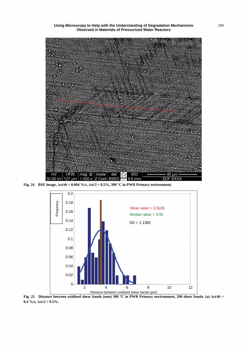
The variation of distance between oxidized shear
bands was also measured using images performed
with the back scattered electron detector in Z-contrast
mode enhancing chemical contrasts (Fig. 24). Results
on 200 assumed shear bands randomly selected at the
surface of the 2 samples are presented in Figs. 25a and
25b. These results clearly demonstrate that distances
between oxidized shear bands increase when strain
rate decreases. Thus at low strain rate, a deeper oxide
penetration along shear bands is coupled with a higher
distance between slip bands. This may induce a
difference of strain localization at the metal/oxide
interface potentially leading to an earlier initiation
stage at low strain rate. The relation between oxide
morphology/structure and strain rate is still
investigated as well as the very first step of
environment interaction and crack initiation.
5. Corrosion of 316 L Austenitic Stainless Steel
5.1 State of the Art
As seen when describing SCC and corrosion fatigue
that are involved microstructural evolution, the
properties of the oxides films play a very important
role as well as in other coupled corrosion/mechanic
degradation mechanisms (flow assisted corrosion,
tribocorrosion...). Many factors affecting corrosion
rate and cracks growth were studied by several authors
[74-83]. Nevertheless, the contribution of the oxide
layers themselves remains crucial and is still suffering
from a lack of understanding. The microstructure and
chemistry of the oxide layers formed on mild steels in
contact with high temperature water was described in
the 60 s by Potter & Mann [84]. They reported that a
double oxide layer composed of an outer layer of large
Fe3O4 crystallites and an inner layer of small Fe3O4
crystallites is formed based on optical and mass
spectroscopy investigations. In the 1980s, working on
stainless steels, Robertson [85] mentioned that the
inner layer was Cr-enriched and consisted of a
chromite spinel rather than chromine Cr2O3. These
observations were detailed twenty year later by
Ziemniak [86] showing that the inner layer was
composed of a fcc spinel with a stochiometry close to
(Ni0.2Fe0.8)(Fe0.3Cr0.7)2O4 and that the outer layer was
Using Microscopy to Help with the Understanding of Degradation Mechanisms Observed in Materials of Pressurized Water Reactors
209
Fig. 24 BSE image, Δεt/dt = 0.004 %/s, Δεt/2 = 0.5%, 300 °C in PWR Primary environment.
2 4 6 8 10 120
0.02
0.04
0.06
0.08
0.1
0.12
0.14
0.16
0.18
0.2
Mean value = 3.5226
Median value = 3.56
SD = 1.1383
Distance between oxidized shear bands (µm)
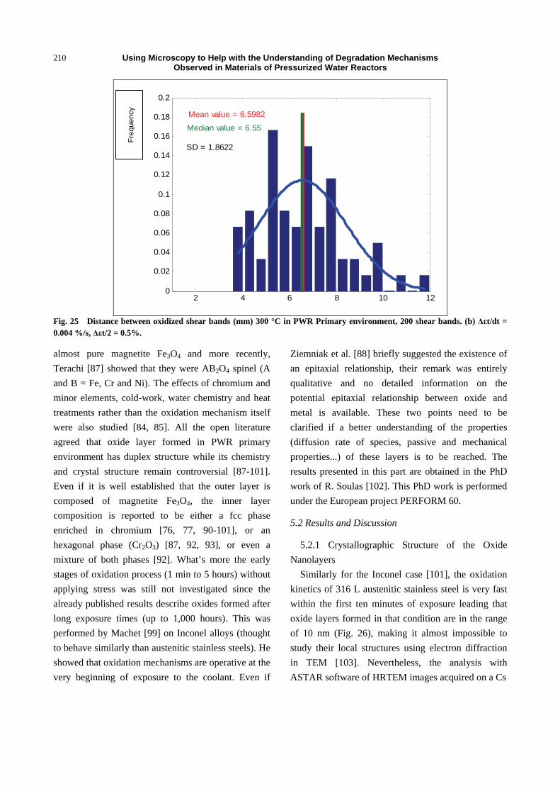
Fig. 25 Distance between oxidized shear bands (mm) 300 °C in PWR Primary environment, 200 shear bands. (a) Δεt/dt = 0.4 %/s, Δεt/2 = 0.5%.
Fre
que
ncy
Using Microscopy to Help with the Understanding of Degradation Mechanisms Observed in Materials of Pressurized Water Reactors
210
2 4 6 8 10 120
0.02
0.04
0.06
0.08
0.1
0.12
0.14
0.16
0.18
0.2
Mean value = 6.5982
Median value = 6.55
SD = 1.8622
Fig. 25 Distance between oxidized shear bands (mm) 300 °C in PWR Primary environment, 200 shear bands. (b) Δεt/dt = 0.004 %/s, Δεt/2 = 0.5%.
almost pure magnetite Fe3O4 and more recently,
Terachi [87] showed that they were AB2O4 spinel (A
and B = Fe, Cr and Ni). The effects of chromium and
minor elements, cold-work, water chemistry and heat
treatments rather than the oxidation mechanism itself
were also studied [84, 85]. All the open literature
agreed that oxide layer formed in PWR primary
environment has duplex structure while its chemistry
and crystal structure remain controversial [87-101].
Even if it is well established that the outer layer is
composed of magnetite Fe3O4, the inner layer
composition is reported to be either a fcc phase
enriched in chromium [76, 77, 90-101], or an
hexagonal phase (Cr2O3) [87, 92, 93], or even a
mixture of both phases [92]. What’s more the early
stages of oxidation process (1 min to 5 hours) without
applying stress was still not investigated since the
already published results describe oxides formed after
long exposure times (up to 1,000 hours). This was
performed by Machet [99] on Inconel alloys (thought
to behave similarly than austenitic stainless steels). He
showed that oxidation mechanisms are operative at the
very beginning of exposure to the coolant. Even if
Ziemniak et al. [88] briefly suggested the existence of
an epitaxial relationship, their remark was entirely
qualitative and no detailed information on the
potential epitaxial relationship between oxide and
metal is available. These two points need to be
clarified if a better understanding of the properties
(diffusion rate of species, passive and mechanical
properties...) of these layers is to be reached. The
results presented in this part are obtained in the PhD
work of R. Soulas [102]. This PhD work is performed
under the European project PERFORM 60.
5.2 Results and Discussion
5.2.1 Crystallographic Structure of the Oxide
Nanolayers
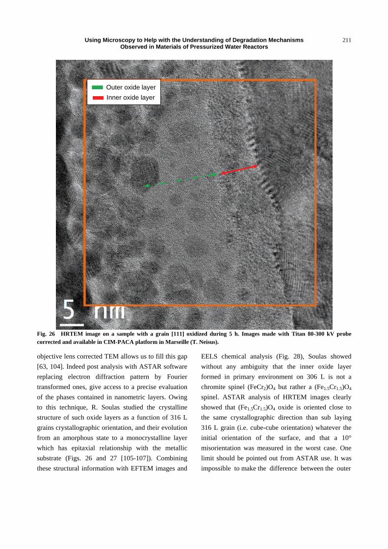
Similarly for the Inconel case [101], the oxidation
kinetics of 316 L austenitic stainless steel is very fast
within the first ten minutes of exposure leading that
oxide layers formed in that condition are in the range
of 10 nm (Fig. 26), making it almost impossible to
study their local structures using electron diffraction
in TEM [103]. Nevertheless, the analysis with
ASTAR software of HRTEM images acquired on a Cs
Fre
que
ncy
Using Microscopy to Help with the Understanding of Degradation Mechanisms Observed in Materials of Pressurized Water Reactors
211
Fig. 26 HRTEM image on a sample with a grain [111] oxidized during 5 h. Images made with Titan 80-300 kV probe corrected and available in CIM-PACA platform in Marseille (T. Neisus).
objective lens corrected TEM allows us to fill this gap
[63, 104]. Indeed post analysis with ASTAR software
replacing electron diffraction pattern by Fourier
transformed ones, give access to a precise evaluation
of the phases contained in nanometric layers. Owing
to this technique, R. Soulas studied the crystalline
structure of such oxide layers as a function of 316 L
grains crystallographic orientation, and their evolution
from an amorphous state to a monocrystalline layer
which has epitaxial relationship with the metallic
substrate (Figs. 26 and 27 [105-107]). Combining
these structural information with EFTEM images and
EELS chemical analysis (Fig. 28), Soulas showed
without any ambiguity that the inner oxide layer
formed in primary environment on 306 L is not a
chromite spinel (FeCr2)O4 but rather a (Fe1.5Cr1.5)O4
spinel. ASTAR analysis of HRTEM images clearly
showed that (Fe1.5Cr1.5)O4 oxide is oriented close to
the same crystallographic direction than sub laying
316 L grain (i.e. cube-cube orientation) whatever the
initial orientation of the surface, and that a 10°
misorientation was measured in the worst case. One
limit should be pointed out from ASTAR use. It was
impossible to make the difference between the outer
Outer oxide layer
Inner oxide layer

Using Microscopy to Help with the Understanding of Degradation Mechanisms Observed in Materials of Pressurized Water Reactors
212
Fig. 27 ASTAR orientation map obtained on the orange square plotted on Fig. 26.
Fig. 28 (a) EFTEM images of O, Fe, Cr and Ni recorded from the sample oxidized 5 hours. (b) Cr/Fe and Ni/(Cr+Fe) variations in metal, nickel enriched layer, inner and outer oxide layer.
iron spinel and the inner chromium rich spinel because
of the small difference of their lattice parameter (less
than 1%).
Applying this mythology to the oxide layers formed
at different exposure times in primary water, Soulas et
al. [105] was able to describe the first step sequences
of the oxide growth on 316 L down to the atomic
scale.
5.2.2 Epitaxial Relationship between Oxide and
Metal; Misfit Dislocations Network at Metal & Oxide
Interface
By selecting reflections in the FFT (Fast Fourier
Transform) patterns of HRTEM images (Fig. 29a),
IFFT (inverse fast Fourier transform) images in
known directions can be reconstructed (Fig. 29b). The
IFFT images corresponding to (002) and (00-2)
reflections displayed in Fig. 29b, clearly show that the
interfacial misfit is accommodated by dislocations
every 1.26 nm. Knowing orientation and lattice
parameter of the inner layer and of the metal,
calculations showed that a deformation of 16% has to
be applied to accommodate if no dislocations are
created. By creating dislocations every 7 planes, the
deformation is reduced to an elastic deformation less

Using Microscopy to Help with the Understanding of Degradation Mechanisms Observed in Materials of Pressurized Water Reactors
213
Fig. 29 HRTEM analysis of the misfit dislocations network lying at metal/oxide. (a) Magnified zone at the metal/oxide interface presented in (Fig.), insert corresponding with a [002] and [00-2] reflections circled.
Fig. 29 HRTEM analysis of the misfit dislocations network lying at metal/oxide. (b) Inverse FFT on selected reflections; (a)
Magnified zone showing perfect edge dislocations network (periodicity: 7 planes) with the Burger’s vector [202].
(a)
(b)

Using Microscopy to Help with the Understanding of Degradation Mechanisms Observed in Materials of Pressurized Water Reactors
214
710 715 720 725 730 735 7400.0
2.0x10⁵
4.0x10⁵
6.0x10⁵
8.0x10⁵
1.0x10⁶
1.2x10⁶
Inte
nsit
y /u
.a.
Energy loss /eV
Metal Inner oxide layer Outer oxide layer
(a)
Fig. 30 EELS and HREELS spectrum on L3/L2 Iron edge obtained on the oxide layers (a) Measure of the energy shift based on internal standard (energy spread 0.7 eV, 316 L oxidation time oxidation time 2 mn).
710 720
0.0
5.0x10³
1.0x10⁴
1.5x10⁴
2.0x10⁴
2.5x10⁴
3.0x10⁴
Inte
nsit
y /u
.a.
Energy loss /eV
Metal Inner oxide layer Outer oxide layer
(b)
Fig. 30 EELS and HREELS spectrum on L3/L2 Iron edge obtained on the oxide layers (b) Details of the Fe L3/L2 edge using a monochromated beam (energy spread 0.2 eV, 316 L oxidation time 2 mn).
than 3%. Theoretically, a perfect edge dislocation
induces a displacement of 2
2a i.e. of 2.54 Å. With a
10° misorientation, this value decreases to 2.50 Å
which appears to be enough for accommodating the
difference between metal and inner oxide parameters.
5.3 Study of the Oxydation Degree
As previously mentioned, the inner oxide layer on
316 L is transforming from nanocrystallites spinel
mixture to a monocrystalline chromium rich spinel
layer during the first ten minutes of exposure to
Fe3+ Fe2+

Using Microscopy to Help with the Understanding of Degradation Mechanisms Observed in Materials of Pressurized Water Reactors
215
primary environment. EELS spectrometry was used
for studying the evolution of metallic compounds.
Some of the results obtained on a Cs condenser
corrected and monochromated TITAN at EDF R&D
are presented in Fig. 30. A few eV shift of the L3/L2
edge toward the higher energy losses are observed
when getting from metal to the oxide (Fig. 30a). When
using a monochromated beam a clear splitting of the
L3/L2 bands is observed in the oxide indicating that
iron has two oxidation state in the oxide Fe2+ and Fe3+
(Fig. 30b) [107]. Quantifying this ratio and its
variation according to corrosion time and oxide
thickness, will give us the possibility to know if the
spinel oxide is normal, intermediate or inversed and
thus to get some new information on the passive
property of the oxide films.
6. General Conclusion
Development of microcopy techniques such
LAWATAP, Dual Beam (low kV ion, 3D facilities),
aberration corrected TEM and STEM with or without
a monochromated beam now gives access to valuable
quantitative information for improving the
understanding of materials degradations observed in
PWR reactors. It was seen that the observed
segregation on dislocations loops is an important key
for improving the understanding and modeling of
hardening mechanisms in irradiated stainless steel and
their contribution to IASCC susceptibility. 3D images
using dual beam and analysis of oxide topography as a
function of cyclic solicitation parameters clearly
underlined the coupling effect on primary
environment under cyclic loading in 304 L.
Deformation mapping along strain path coupled with
TEM studies on specimen with perfectly known strain
path, strain amplitude and crystallographic orientation
with dual beam microscope gave access to a precise
evaluation of the interaction of mechanical solicitation
on oxide and cracks growth. A clear effect of strain
and its speed, and also of the nature of mechanical
loading (tensile or cyclic loading) on corrosion
behavior was shown. The oxidation mechanism can
now be better understood thank to the combination of
all these advanced techniques.
References
[1] Lucas, G. E. 1993. “The Evolution of Mechanical Property Change in Irradiated Austenitic Stainless Steels.” J. Nucl. Mater. 206: 287.
[2] Pokor, C. 2002. “Caractérisation microstructurale et modélisation du durcissement des aciers austénitiques irradiés des structures internes des réacteurs à eau pressurisée.” Ph.D. Thesis, INP Grenoble.
[3] Pokor, C. 2004. “Irradiation Damage in 304 and 316 Stainless Steels: Experimental Investigation and Modeling. Part I: Evolution of the Microstructure.” J. Nucl. Mater. 326 (1): 19-29.
[4] Garnier, J. 2007. “Déformation sous flux des aciers austénitiques des structures internes des réacteurs à eau pressurisée.” Ph.D. Thesis, INP Grenoble.
[5] Etienne, A. 2009. “Etude des effets d’irradiations et de la nanostructuration dans des aciers austénitiques inoxydables. ” Ph.D. Thesis, Rouen.
[6] Was, G. S., et al. 2002. “Emulation of Neutron Irradiation Effects with Protons: Validation of Principle.” J. Nucl. Mater. 300 (2-3): 198-216.
[7] Gan, J. 2004. “The Effect of Oversized Solute Additions on the Microstructure of 316SS Irradiated with 5 MeV Ni++ ions or 3.2 MeV Protons.” J. Nucl. Mater. 325 (2-3): 94-106.
[8] Cauvin, R., Goltrant, O., Rouillon, Y., Verzaux, E., Cazus, A., Dubuisson, P., Poitrenaud, P., and Bellet, S. 1994. “Endommagement des Structures Internes Inférieures Soumises à Fortes Fluences: Apports de l’Expertise.” In Proceedings of the International Symposium Fontevraud III, Société Française d’Energie Nucléaire, 54.
[9] Pironet, G., Heuzé, A., Goltrant, O., and Cauvin, R. 1998. “Expertise des vis de Liaison Cloison-Renfort de la Central de Tihange 1.” In Proceedings of the International Symposium Fontevraud IV, Société Française d’Energie Nucléaire, 195.
[10] Goltrant, O., Cauvin, R., Deydier, D., and Trenty, A. 1998. “Eléments Internes Inférieurs: Apports de l’Expertise d’une Cornière de Chooz A.” In Proceedings of the International Symposium Fontevraud III, Société Française d’Energie Nucléaire, 183.
[11] Monnet, I., Decroix, G. M., Dubuisson, P., Reuchet, J., and Morlent, O. 1998. “Investigation of the Choz A Nuclear Power Plant Bolts.” In Proceedings of the International Symposium Fontevraud IV, Société Française d’Energie Nucléaire, 371.

Using Microscopy to Help with the Understanding of Degradation Mechanisms Observed in Materials of Pressurized Water Reactors
216
[12] Scott, P. 1994. “A Review of Irradiation Assisted Stress Corrosion Cracking.” J. of Nucl. Mater. 211-2: 101.
[13] Williams, J. F., Mager, T. R., Spellward, P., Walmsley, J., Koyama, M., Suzuki, I., and Mimaki, H. 1997. “Microstructural Effects in Austenitic Stainless Steel Materials Irradiated in a Pressurized Water Reactor.” In Proceedings of 8th International Symposium on Environmental Degradation of Materials in Nuclear Power Systems—Water Reactors, 725.
[14] Busby, J. T., Was, G. S., and Kenik, E. A. 2002. “Isolating the Effect of Radiation-Induced Segregation in Irradiation-Assisted Stress Corrosion Cracking of Austenitic Stainless Steels.” J. Nucl. Mater. 302-1: 20.
[15] Bruemmer, S. M., Simonen, E. P., Scott, P. M., Andresen, P. L., Was, G. S., and Nelson, J. L. 1999. “Radiation-Induced Material Changes and Susceptibility to Intergranular Failure of Light-Water-Reactor Core Internals.” J. Nucl. Mater. 274-3: 299.
[16] Bruemmer, S. M., Charlot, L. A., and Simonen, E. P. 1995. “Measurement and Modeling of Radiation Induced Grain Boundary Segregation in Stainless Steels.” Presented at the 7th International Symposium Environmental Degradation of Materials in Nuclear Power Systems—Water Reactors, Breckenridge, Colorado, USA.
[17] Fukuya, K., Nakano, M., Fujii, K., and Torimaru, T. 2004. “IASCC Susceptibility and Slow Tensile Properties of Highly-Irradiated 316 Stainless Steels.” J. Nucl. Sci. Technol. 41: 594.
[18] Was, G. S., and Andresen, P. L. 1992. “Irradiation-Assisted Stress-Corrosion Cracking in Austenitic Alloys.” J. Metals 44: 8.
[19] Was, G. S., and Bruemmer, S. M. 1994. “Effects of Irradiation on Intergranular Stress Corrosion Cracking.” J. Nucl. Mater. 216: 326.
[20] Andresen, P. L., Ford, F. P., Murphy, S. M., and Perks, J. M. 1989. “State of Knowledge of Irradiation Effects on EAC in LWR Core Materials.” In Proceedings of the 4th International Symposium on Environmental Degradation of Materials in Nuclear Power Systems—Water Reactors, Jekyll Island, GA, 1.
[21] Edwards, D. J., Simonen, E. P., Garner, F. A., Greenwood, L. R., Oliver, B. M., and Bruemmer, S. M. 2003. “Influence of Irradiation Temperature and Dose Gradients on the Microstructural Evolution in Neutron-Irradiated 316SS.” J. Nucl. Mater. 317: 32.
[22] Edwards, D. J., Simonen, E. P., and Bruemmer, S. M. 2003. “Evolution of Fine-Scale Defects in Stainless Steels Neutron-Irradiated at 275 °C.” J. Nucl. Mater. 317: 13.
[23] Kenik, E. A., and Hojou, K. 1992. “Radiation-Induced Segregation in FFTF-Irradiated Austenitic Stainless
Steels.” J. Nucl. Mater. 191-4: 1331. [24] Etienne, A., Radiguet, B., Pareige, P., Massoud, J.-P., and
Pokor, C. 2008. “Tomographic Atom Probe Characterization of the Microstructure of a Cold Worked 316 Austenitic Stainless Steel After Neutron Irradiation.” J. Nucl. Mater. 382: 64-9.
[25] Etienne, A., Radiguet, B., and Pareige, P. 2010. “Understanding Silicon-Rich Phase Precipitation Under Irradiation in Austenitic Stainless Steels.” J. Nucl. Mater. 406: 251-6.
[26] Etienne, A., Radiguet, B., Cunningham, N. J., Odette, G. R., and Pareige, P. 2010. “Atomic Scale Investigation of Radiation-Induced Segregation in Austenitic Stainless Steels.” J. Nucl. Mater. 406: 244-50.
[27] Volgin, A. 2012. ‘Characterization and Understanding of Ion Irradiation Effect on the Microstructure of Austenitic Stainless Steels.” Ph.D. thesis, Université de Rouen.
[28] Was, G. S., et al. 1999. “Microchemistry and Microstructure of Proton-Irradiated Austenitic Alloys: Toward an Understanding of Irradiation Effects in LWR Core Components.” J. Nucl. Mater. 270 (1-2): 96-114.
[29] Borodin, O. V., et al. 2009. “Microstructure Evolution and Degradation Mechanisms of Reactor Internal Steel Irradiated with Heavy Ions.” J. Nucl. Mater. 385 (2): 325-8.
[30] Kalchenko, A. S., et al. 2010. “Prediction of Swelling of 18Cr10NiTi Austenitic Steel over a Wide Range of Displacement Rates.” J. Nucl. Mater 399 (1): 114-21.
[31] Gan, J., et al. 2004. “The Effect of Oversized Solute Additions on the Microstructure of 316SS Irradiated with 5 MeV Ni++ ions or 3.2 MeV Protons.” J. Nucl. Mater 325 (2-3): 94-106.
[32] Busby, J. T., Was, G. S., and Kenik, E. A. 2002. “Isolating the Effect of Radiation-Induced Segregation in Irradiation-Assisted Stress Corrosion Cracking of Austenitic Stainless Steels.” J. Nucl. Mater 302: 20-40.
[33] Blavette, D., Bostel, A., Sarrau, J. M., Deconihout, B., and Menand, A. 1993. “An Atom Probe for Three-Dimensional Tomography.” Nature 363: 432-5.
[34] Gault, B., Vurpillot, F., Vella, A., Gilbert, M., Menand, A., Blavette, D., and Deconihout, B. 2006. “Design of a Femtosecond Laser Assisted Tomographic Atom Probe.” Rev. Sci. Instrum. 043705: 77.
[35] Le Hong, S., Amzallag, C., and Gelpi, A. 1999. “Modelling of Stress Corrosion Crack Initiation on Alloy 600 in Primary Water of PWRs.” In Proceedings of the 9th International Symposium on Environmental Degradation of Materials in Nuclear Reactors.
[36] Boursier, J. M., Rouillon, Y., and Le Hong, S. 2000. “Relationship between Microstructure and PWSCC Susceptibility in Wrought Alloy 600.” Presented at the EUROCORR Congress.

Using Microscopy to Help with the Understanding of Degradation Mechanisms Observed in Materials of Pressurized Water Reactors
217
[37] Benhamou, C., and Amzallag, C. 1999. “Influence of Manufacturing Parameters on Stress Corrosion Cracking of Alloy 600 Used in Nuclear Power Plants.” Presented at EUROCORR Congress.
[38] Couvant, T., Moulart, P., Legras, L., Bordes, P., Capelle, J., Rouillon, Y., and Balon, T. 2006. “PW SCC of Austenitic Stainless Steels of Heaters of Pressurizers.” In Proceedings of International Symposium Fontevraud VI, Société Française d’Energie Nucléaire.
[39] Thebault, Y., Moulart, P., Dubourgnoux, K., Champredonde, J., Couvant, T., Neau, Y., Fageon, J. M., Lecharpentier, D., Breuil, A., and Derouet, V. 2011. “PWSCC of Thermocoax Pressurizer Heaters in Austenitic Stainless Steel and Remedial Actions to Preventing SCC.” In Proceedings of 15th International Conference on Environmental Degradation of Materials in Nuclear Systems-Water Reactors, Colorado Springs, (USA).
[40] Bibollet, C., et al. 2006. “Environmental Behavior and Weldability of Ni-base Weld Metals in PWRs.” In Proceedings of International Symposium Fontevraud VI, Société Française d’Energie Nucléaire.
[41] Deforge, D., et al. 2010. “Learnings from EDF Investigations on SG Divider Plates and Vessel Head Nozzles. Evidence of Prior Deformation Effect on Stress Corrosion Cracking.” In Proceedings of International Symposium Fontevraud VII, Société Française d’Energie Nucléaire, Avignon (France).
[42] Miloudi, S., et al. 2011. “Destructive Examinations on Divider Plates from Decommissioned Steam Generators Affected by Superficial Stress Corrosion Cracks.” In Proceedings of 15th International Conference on Environmental Degradation of Materials in Nuclear Systems-Water Reactors, Colorado Springs, (USA).
[43] Couvant, T., Vaillant, F., and Lemaire, E. 2009. “Stress Corrosion Crack Growth Rate in Rolled Alloy 600 Exposed to Primary PWR Environment.” In Proceedings of 14th International Conference on Environmental Degradation of Materials in Nuclear Power Systems-Water Reactor, Virginia Beach (USA).
[44] Couvant, T., Miloudi, S., Vaillant, F., Déforge, D., and Thébault, Y. 2010. “PWSCC of Steam Generator Divider Plates in Alloy 600: Coupling Field Characterizations with RD Studies.” In Proceedings of International Symposium Fontevraud VII, Société Française d’Energie Nucléaire, Avignon, France.
[45] Couvant, T., Legras, L., Pokor, C., Vaillant, F., Brechet, Y., Boursier, J. M., and Moulart, P. 2007. “Investigations on the Mechanisms of PWSCC of Strain Hardened Austenitic Stainless Steels.” In Proceedings of 13th International Conference on Environmental Degradation of Materials in Nuclear Systems-Water Reactors,
Whistler, Canada. [46] Couvant, T., Legras, L., Vaillant, F., Boursier, J. M., and
Rouillon, Y. 2005. “Effect of Strain Hardening on Stress Corrosion Cracking of AISI 304L Stainless Steel in PWR Primary Environment at 360 C.” In Proceedings of 12th International Conference on Environmental Degradation of Materials in Nuclear Systems-Water Reactors, Snowbird, Utah.
[47] Schmitt, J. H., Aernoudt, E., and Baudelet, B. 1985. “Yield Loci for Polycristalline Metals without Texture.” Material Science and Engineering 75: 13-20.
[48] Mesures de champs et identification en mécanique des solides, Ed. Lavoisier, 2011.
[49] Solomon, H. D., Amzallag, C., DeLair, R. E., and Vallee, A. J. 2005. “Comparison of the Fatigue Life of Type 304L SS as Measured in Load and Strain Controlled Tests.” In Proceedings of 12th International Conference on Environmental Degradation of Materials in Nuclear Systems-Water Reactors, Snowbird, Utah, 1101-10.
[50] Japan Nuclear Energy Safety Organization. 2007. “The Final Report of EFT Project.” 07 kizaihou-0002.
[51] Chopra, O. K., and Shack, W. J. 2007. Final Report, NUREG/CR-6909, ANL-06/08.
[52] Bernard, M., Vogt, J. B., Bui-Quoc, T., and Dickson, J. I. 1984. “Low-Cycle Fatigue Behaviour and Cumulative Damage Effect of 316 Stainless Steel at 20°, 427° and 650 °C.” In Proceedings of the 2nd International Conference on Fatigue and Fatigue Thresholds at the University of Birmingham, Fatigue 84, 2: 1029-38.
[53] Gerland, M., Mendez, J., Violan, P., and Ait Saadi, B. 1989. “Evolution of Dislocation Structures and Cyclic Behaviour of a 316L-Type Austenitic Stainless Steel Cycled in Vacuo at Room Temperature.” Materials Science and Engineering A A118: 83-95.
[54] Gerland, M., Alain, R., Ait Saadi, B., and Mendez, J. 1997. “Low Cycle Fatigue Behaviour in Vacuum of a 316L-Type Austenitic Stainless Steel between 20 and 600 °C—Part II: Dislocation Structure Evolution and Correlation with Cyclic Behaviour.” Materials Science and Engineering A A229 (1-2): 68-86.
[55] Obrtlik, K., Kruml, T., and Polak, J. 1994. “Dislocation Structures in 316L Stainless Steel Cycled with Plastic Strain Amplitudes over a Wide Interval.” Materials Science and Engineering A A187 (1): 1-9.
[56] Brun, G., Gauthier, J. P., and Petrequin, P. 1976. “Etude de la Fatigue Oligocyclique d'un Acier Z2 CND 17-12 (type AISI 316L).” Presented at Journées Métallurgique d'Automne 1974, Société Française de Métallurgie, Mémoires Scientifiques Revue Métallurgie, Juillet-Août, 461-83.
[57] Vingsbo, O., Lagerberg, G., Hansson, B., and Bergstrom, Y. 1968. “Dislocation Structure of an Austenitic Stainless

Using Microscopy to Help with the Understanding of Degradation Mechanisms Observed in Materials of Pressurized Water Reactors
218
Steel in Different Stages of Fatigue.” Philosophical Magazine 17 (147): 441-51.
[58] Magnin, T. 1991. “Développements Récents en Fatigue Oligocyclique sous l’Angle de la Métallurgie Physique.” Presented at Journées Métallurgique d'Automne 1989, Société Française de Métallurgie, Mémoires et Etudes Scientifiques Revue de Métallurgie Janvier: 33-48.
[59] Li, Y., and Laird, C. 1994. “Cyclic Response and Dislocation Structures of AISI 316L Stainless Steel. Part 1: Single Crystals Fatigued at Intermediate Strain Amplitude.” Materials Science and Engineering A A186 (1-2): 65-86.
[60] Li, Y., and Laird, C. 1994. “Cyclic Response and Dislocation Structures of AISI 316L Stainless Steel. Part 2: Single Crystals Fatigued at Intermediate Strain Amplitude.” Materials Science and Engineering A A186 (1-2): 87-103.
[61] Garcia, A. 2009. “Caractérisation Microstructurale D'aciers Inoxydables Austenitiques de Type AISI 304L Sollicités en Fatigue.” PhD Thesis, Institut National Polytechnique de Grenoble.
[62] Wright, S. I., Dingley, D. J., 1998. “Orientation Imaging in the Transmission Electron Microscope.” Mater. Sci. Forum 209: 273-275.
[63] Rauch, E. F., Veron, 2005. M. “Coupled Microstructural Observations and Local Texture Measurements with an Automated Crystallographic Orientation Mapping Tool Attached to a TEM.” J. Mater. Sci. Eng. Tech. 552: 36.
[64] Garcia, A., Legras, L., Akamatsu, M., Bréchet, Y. 2008. “EMC Aachen.” J. Mater. Sci. 2: 427-8.
[65] Alain, R. 1993. “Comportement en Fatigue Plastique d'un Acier Inoxydable Austénitique Type 316L Entre 20 °C et 600 °C. Etude des Facteurs Gouvernant la Durée de vie.” Ph.D. thesis, Université de Poitiers.
[66] Legras, L. 2011. “Préparation D’Échantillons par Microscope Double Faisceau Pour Observations par MEB Équipé d’un Détecteur STEM ou par MET.” In préparation des échantillons pour MEB et Microanalyse, edited by P Jonnard and F Brisset, isbn 978-2-7598-0676-8, EDP Sciences, 137-66.
[67] Huin, N., 2013. “Effets d'environnement Sur la Fatigue de l'acier Inoxydable 304L en Milieu Primaire REP Sous Chargement Cyclique.” PhD thesis, ISAE-ENSMA Poitiers.
[68] Man, J., Vystavel, T., Weidner, A., Kubena, I., Petrenec, M., Kruml, T., and Polak, J. 2012. “Study of Cyclic Strain Localization and Fatigue Crack Initiation Using FIB Technique.” International Journal of Fatigue 39: 44-53.
[69] Sabatier, L. 2002. “Apport des Techniques d’analyse locale EBSD et AFM à l’étude de l’émergence des bandes de Glissements Induites par Fatigue dans l’acier Inoxydable 316L. Influence des Couches Minces.” Ph.D.
Thesis, Université de Poitiers. [70] Mineur, M. 2000. “Conditions locales d’amorçage des
fissures de fatigue dans un acier inoxydable de type 316L: aspects cristallographiques (EBSD).” Ph.D. Thesis, University of Poitiers.
[71] Huin, N., Tsutsumi, K., Legras, L., Couvant, T., Loisnard, D., Henaff, G., and Mendez, J. 2012. “Fatigue Crack Initiation of 304L Stainless Steel in Simulated PWR Primary Environment: Relative Effect of Strain Rate.” In Proceedings of the ASME 2012 Pressure Vessels and Piping Conference, 165-71.
[72] Huin, N., Couvant, Tsutsumi, K., Legras, Henaff, G., and Mendez, J. 2011. “Environmental Effect on Cracking of Austenitic Stainless Steels Exposed to PWR Primary Water Under Cyclic Loading.” In Proceedings of the Eurocorr Congress, 1631-46.
[73] Couvant, T., Legras, L., Herbelin, A., Musienko, A., Ilevbare, G., Delafosse, D., Cailletaud, G., and Hickling, J. 2009. “Development of Understanding of the Interaction between Localized Deformation and SCC of Austenitic Stainless Steels Exposed to Primary PWR Environment.” In Proceedings of the 14th International Conference on Environmental Degradation of Materials in Nuclear Power Systems Virginia Beach, 182-94.
[74] Moore, J. B., and Jones, R. L. 1968. “Growth Characteristics of Iron Oxide Films Generated in Dilute Lithium Hydroxide Solution at 300 °C.” J. Electrochem. Soc. 576: 115.
[75] Boursier, J. M., Desjardins, D., and Vaillant, F. 1995. “The Influence of the Strain-Rate on the Stress Corrosion Cracking of Alloy 600 in High Temperature Primary Water.” Corrosion Science 493: 37.
[76] Petrequin, P. 1997. Effect of Irradiation on Water Reactor Internals. ASME report n 11 (1997), COSU CT 94-074, EUR 17694 EN.
[77] Pathania, R. 2002. Quantification of Yield Strength Effects on IGSCC in Austenitic Stainless Steels and Its Implication to IASCC. EPRI report 1007380.
[78] Couvant, T., Vaillant, F., Boursier, J. M., and Delafosse, D. 2004. “Effect of Strain-Path on Stress Corrosion Cracking of AISI 304L Stainless Steel in PWR Primary Environment at 360 °C.” In Proceedings of the Eurocorr 2004, Nice.
[79] Huang, Y., and Titchmarsh, J. 2006. “TEM Investigation of Intergranular Stress Corrosion Cracking for 316 Stainless Steel in PWR Environment.” Acta. Materialia 635: 54.
[80] Lozano-Perez, S., Schröder, M., Yamada, T., Terachi, T., English, C. A., and Grovenor, C. R. M. 2008. “Using NanoSIMS to Map Trace Elements in Stainless Steels from Nuclear Reactors.” Applied Surface Science 1541: 255.

Using Microscopy to Help with the Understanding of Degradation Mechanisms Observed in Materials of Pressurized Water Reactors
219
[81] Lozano-Perez, S., Yamada, T., Terachi; T., Schröder, M., English, C. A., Smith, G. D. W., Grovenor, C. R. M., and Eyre, B. L. 2009. “Multi-scale Characterization of Stress Corrosion Cracking of Cold-Worked Stainless Steels and the Influence of Cr Content.” Acta. Materialia 5361: 57.
[82] Lozano-Perez, S., Saxey, D. W., Yamada, T., and Terachi, T. 2010. “Atom-Probe Tomography Characterization of the Oxidation of Stainless Steel.” Scripta Materialla 855: 62.
[83] Lozano-Perez, S., Rodrigo, P., and Gontard, L. C. 2011. “Three-Dimensional Characterization of Stress Corrosion Cracks.” J. Nucl. Mater. 289: 408.
[84] Potter, E. C., and Mann, G. M. W. 1961. “Oxidation of Mild Steel in High-Temperature Aqueous Systems.” In Proceedings of the 1st International Congress of Metallic Corrosion, 417-26.
[85] Robertson, J. 1991. “The Mechanism of High Temperature Aqueous Corrosion of Stainless Steels.” Corrosion Science 443: 32.
[86] Ziemnial, S. E., and Hanson, M. 2002. “Corrosion Behavior of 304 Stainless Steel in High Temperature, Hydrogenated Water.” Corrosion Science 2209: 44.
[87] Terachi, T., Fujii, K., and Arioka, K. 2005. “Microstructural Characterization of SCC Crack Tip and Oxide Film for SUS 316 Stainless Steel in Simulated PWR Primary Water at 320 °C.” J. Nucl. Sci. and Tech. 225: 42.
[88] Howes, V. R. 1967. “Microstructural Characterization of SCC Crack Tip and Oxide Film for SUS 316 Stainless Steel in Simulated PWR Primary Water at 320 °C.” Corrosion Science 735: 7.
[89] Bignold, G. J., Garnseyand, R., and Mann, G. M. W. 1972. “High Temp. Aqueous Corrosion of Iron Development of Theories of Equilibrium Solution Phase Transport through a Porous Oxide.” Corrosion Science 325: 12.
[90] Ensling, J., Fleisch, J., Grimm, R., Gruber, J., and Gutlich, P. 1978. “A Corrosion Study of Austenitic and Martensitic Steels under Boiler Conditions by Means of 57 Fe Conversion Electron Mössbauer Spectroscopy.” Corrosion Science 797: 18.
[91] Hultquist, G., and Leygraf, C. 1982. “The Initiation of Selective Oxidation of a Ferritic Stainless Steel at Low Temperatures and Oxygen Pressures.” Corrosion Science 331: 22.
[92] Greyling, C. J., and Rous, J. P. 1984. “Optimum Conditions in the Thermal Passivation of AISI 430 and 304 Stainless Steel in Controlled Oxygen Atmosphere.” Corrosion Science 675: 24.
[93] Tapping, R. L., Davidson, D., McAlpine, E., and Lister, D. H. 1986. “The Composition and Morphology of Oxide Films Formed on Type 304 Stainless Steel in Lithiated
High Temperature Water.” Corrosion Science 563: 26. [94] Langevoort, J. C., Sutherland, I., Hanekamp, L. J., and
Gellinges, P. J. 1987. “On the Oxide Formation on Stainless Steels AISI 304 and Incoloy 800H Investigated with XPS.” Appl. Surf. Sci. 167: 28.
[95] Lister, D. H., Davidson, R. D., and McAlpine, E. 1987. “The Mechanism and Kinetics of Corrosion Product Release from Stainless Steel in Lithiated High Temperature Water.” Corrosion Science 113: 27.
[96] Szklarska-Smialowska, Z., Chou, K. C., and Xia, Z. 1991. “The Composition and Properties of Oxide Films on Type 304 Stainless Steel on Exposure to Lithiated Water at 100-350 °C.” Corrosion Science 609: 32.
[97] Stellwag, B. 1998. “The Mechanism of Oxide Film Formation on Austenitic Stainless Steels in High Temperature Water.” Corrosion Science 337: 40.
[98] Da Cunha Belo, M., Walls, M., Hakiki, N. E., Corset, J., Picqenard, E., Sagon, G., and Noel, D. 1998. “Composition, Structure and Properties of the Oxide Films Formed on the Stainless Steel 316L in a Primary Type PWR Environment.” Corrosion Science 447: 40.
[99] Machet, A., Galtayries, A., Zanna, S., Klein, S. L., Maurice, V., Jolivet, P., Foucault, M., Combrade, P., Scott, P., and Marcus, P. 2004. “XPS and STM Study of the Growth and Structure of Passive Films in High Temperature Water on a Nickel-Base Alloy.” Electrochimica Acta. 3957: 49.
[100] Kerrec, O., Gardey, S., Noel, D., Riquelme, E., Miguet, P., and Massoud, J. P. 1996. “Influence of Initial Surface State on the Corrosion Behaviour of Nickel Alloys in Primary Coolant Medium.” Eurocorr, Nice.
[101] Gardey, S. 1998. “Etude de la corrosion généralisée des alliages 600, 690 et 800 en milieu primaire. Contribution à la compréhension des mécanismes.” Ph.D. Thesis, Université Pierre et Marie Curie, Paris VI.
[102] Soulas, R., 2012. “Effet de la cristallographie sur les premiers stades de l’oxydation des aciers austénitiques 316L.” Ph.D. Thesis, INP Grenoble.
[103] Soulas, R., Cheynet, M., Rauch, E., Neisius, T., Legras, L., Domain, C. and Brechet, Y. 2012. “Structural and Chemical Investigations of the Oxide Formed on 316L Alloy in PWR Environment.” Presented at the E-MRS 2012, Strasbourg.
[104] Moeck, P., Rouvimov, S., Rauch, E. F., Veron, M., Kirmse, H., Hausler, I., Neumann, W., Bultreys, D., Maniette, Y., and Nicolopoulos, S. 2011. “High Spatial Resolution Semi-Automatic Crystallite Orientation and Phase Mapping of Nanocrystals in Transmission Electron Microscopes.” Crystal Research and Technology 589: 46.
[105] Soulas, R., Legras, L., Brechet, Y., Cheynet, M., Domain, C., et al. 2010. “Analyse Chimique et Cristallographique des Oxydes Formés en milieu REP sur l’acier 316L.”
Using Microscopy to Help with the Understanding of Degradation Mechanisms Observed in Materials of Pressurized Water Reactors
220
Presented at the Pasturel., 25th conference of SFME, Strasbourg.
[106] Soulas, R., Legras, L., Brechet, Y., Cheynet, M., Domain, C., and Pasturel, A. 2011. “Crystallographic and Plasticity Effects on the First Oxidation Steps of Stainless
Steel 316L.” Presented at the EUROCORR Conference, Stockholm, Sweden.
[107] Soulas, R. 2012. “Effet de la cristallographie sur les premiers stades de l’oxydation des aciers austénitiques 316L.” Ph.D. Thesis, INP Grenoble.