Nonlinear Vibration of Plates by the Hierarchical Finite Element and ...

50
Int. J. Mech. Eng. & Rob. Res. 2015 Arshad Mehmood, 2015
USING FINITE ELEMENT METHOD VIBRATIONANALYSIS OF FRAME STRUCTURE SUBJECTED TO
MOVING LOADS
Arshad Mehmood1*
*Corresponding Author: Arshad Mehmood,[email protected]
It was purposed to understand the dynamic response of frame which are subjected to movingpoint loads. The finite element method and numerical time integration method (New mark method)are employed in the vibration analysis. The effect of the speed of the moving load on the dynamicmagnification factor which is defined as the ratio of the maximum dynamic displacement at thecorresponding node in the time history to the static displacement when the load is at the mid-point of the structure is investigated. The effect of the spring stiffness attached to the frame atthe conjunction points of beam and columns are also evaluated. Computer codes written in Matlab are developed to calculate the dynamic responses. Dynamic responses of the engineeringstructures and critical load velocities can be found with high accuracy by using the finite elementmethod.
Keywords: Beam, Finite element methods, Numerical tine integration method, Dynamicmagnification factors, Stiffness, Shape function, Critical load velocity
INTRODUCTIONVibration analysis of structures has been ofgeneral interest to the scientif ic andengineering communities for many years.These structures have multitude ofapplications in almost every industry. Theaircraft industry has shown much interest inthis, some of the early solutions weremotivated by this industry. This study dealswith the finite element analysis of themonotonic behavior of beams, slabs and
ISSN 2278 – 0149 www.ijmerr.comVol. 4, No. 1, January 2015
© 2015 IJMERR. All Rights Reserved
Int. J. Mech. Eng. & Rob. Res. 2015
1 Mechanical Engineering Department, Zakir Husain College of Engineering & Technology, AMU, Aligarh, India.
beam-column joint sub assemblages. It isassumed that the behavior of these memberscan be described by a plane stress field.Reinforced concrete has become one of themost important building materials and is widelyused in many types of engineering structures.The economy, the efficiency, the strength andthe stiffness of reinforced concrete make it anattractive material for a wide range of structuralapplications. For its use as structural material,concrete must satisfy the following conditions:
Research Paper
51
Int. J. Mech. Eng. & Rob. Res. 2015 Arshad Mehmood, 2015
The Structure Must be Strong and Safe:The proper application of the fundamentalprinciples of analysis, the laws of equilibriumand the consideration of the mechanicalProperties of the component materials shouldresult in a sufficient margin of safety againstcollapse under accidental overloads.
The Structure Must be Stiff and AppearUnblemished: Care must be taken to controldeflections under service loads and to limit thecrack width to an acceptable level.
The Structure Must be Economical:Materials must be used efficiently, since thedifference in unit cost between concrete andsteel is relatively large. Moving loads haveconsiderable effects on the dynamic behaviorof the engineering structure. Transportengineering frame structures such as bridgesare subjected to loads that vary in both timeand space (moving forces), in the form ofvehicular traffic, which cause them to vibrate.A moving vehicle on a bridge causesdeflections and stresses that are generallygreater than those caused by the samevehicular loads applied statically. The dynamicanalysis of a structure subjected to a movingload is an old topic of research; hence a lot ofliterature exists. Olsson (1991) studied thedynamics of a beam subjected to a constantforce moving at a constant speed andpresented analytical and finite elementsolutions. Thambiratnam and Zhuge (1996)studied the dynamics of beams on an elasticfoundation and subjected to moving loads byusing the finite element method. Theyinvestigated the effect of the foundationstiffness, travelling speed and the span lengthof the beam on the dynamic magnificationfactor, which is defined as the ratio of the
maximum displacement in the time history ofthe mid-point to the static midpointdisplacement. Wang (1997) analyzed the multi-span Timoshenko beams subjected to aconcentrated moving force by using the modesuperposition method and made a comparisonbetween the Euler-Bernoulli beam andTimoshenko beam. Zheng et al. (1998)analyzed the vibration of a multi span nonuniform beam subjected to a moving load byusing modified beam vibration functions as theassumed modes based on Hamilton’s principle.The modified beam vibration functions satisfythe zero deflection conditions at all theintermediate point supports as well as theboundary conditions at the two ends of thebeam. Numerical results are presented for bothuniform and non-uniform beams under movingloads of various velocities. Wang and Lin (1998)studied the vibration of multi-span Timoshenkoframes due to moving loads by using the modalanalysis. Kadivar and Mohebpour (1998)analyzed the dynamic responses ofunsymmetrical composite laminated orthotropicbeams under the action of moving loads. Hongand Kim (1999) presented the modal analysisof multi span Timoshenko beams connected orsupported by resilient joints with damping. Theresults are compared with FEM. Ichikawa et al.(2000) investigated the dynamic behavior of themulti-span Continuous beam traversed by amoving mass at a constant velocity, in which itis assumed that each span of the continuousbeam obeys uniform Euler-Bernoulli beamtheory.
Dynamic Analysis by NumericalIntegrationDynamic response of structures under movingloads is an important problem in engineering

52
Int. J. Mech. Eng. & Rob. Res. 2015 Arshad Mehmood, 2015
and studied by many researchers. Thenumerical solution can be calculated by variousmethods which are as follows:
1. Duhamel Integral
2. New mark Integration method
3. Central difference Method
4. Houbolt Method
5. Wilson Method
New Mark Family of MethodsThe New mark integration method is basedon the assumption that the Acceleration varieslinearly between two instants of time. In 1959new mark presented a family of single-stepintegration methods for the solution of structuralDynamic problems for both blast and seismicloading. During the past 45 years new markmethod has been applied to the dynamicanalysis of many practical engineeringstructures. In addition, it has been modifiedand improved by many other researchers. Inorder to illustrate the use of this family ofnumerical integration methods, we consideredthe solution of the linear dynamic equilibriumequations written in the following form:
tttt FuKuCuM ...(1)
where M is the mass matrix, C is the dampingmatrix and K is the stiffness matrix.
u , uu, are the acceleration, velocity anddisplacement vectors, respectively Ft is theexternal loading vector. The direct use ofTaylor’s series provides a rigorous approachto obtain the following two additional equations:
ttttttttt utututuu
62
32
...(2)
ttttttt ututuu
2
2
...(3)
New mark truncated these equations andexpressed them in the following form:
utututuu ttttttt 3
2
2
...(4)
ututuu ttttt 2 ...(5)
If the acceleration is assumed to be linearwithin the time step, the following equation canbe written as:
tuuu ttt
...(6)
The substitution of Equation (6) intoEquations (4) and (5) produces new mark’sequations in standard form
tttttttt utututuu 22
21
...(7)
tttttt ututuu 1 ...(8)
Stability of New Mark MethodFor zero damping new mark method isconditionally stable if
2
121,
21
max
tand...(9)
where max is the maximum frequency in thestructural system New mark’s method isunconditionally stable if
212 ...(10)
However, if is greater than 1/2, errors areintroduced. These errors are associated with“numerical damping” and “period elongation”.For large multi degree of freedom structuralsystems the time step limit, given by Equation(9), can be written in a more usable form as:

53
Int. J. Mech. Eng. & Rob. Res. 2015 Arshad Mehmood, 2015
2
2
1
minTt
...(11)
where Tmin is the minimum time period of thestructure. Computer model of larger structuresnormally contain a large number of periodswhich are smaller than the integration timestep; therefore, it is essential that one select anumerical integration method that isunconditionally stable for all time steps. Table1 shows the summary of the New mark methodfor direct integration.
Solution Using Finite ElementMethodFinite Element Method (FEM) is a numericalmethod for solving a differential or integral
equation. It has been applied to a number ofphysical problems, where the governingdifferential equations are available. The methodessentially consists of assuming the piecewisecontinuous function for the solution andobtaining the parameters of the functions in amanner that reduces the error in the solution.
A promising approach for developing asolution for structural vibration problems isprovided by an advanced numericaldiscretization scheme, such as, Finite ElementMethod (FEM). The FEM is the dominantdiscretization technique in structuralmechanics.
The basic concept in the physical FEM isthe subdivision of the mathematical model intodisjoint (non-overlapping) components ofsimple geometry called finite elements orelements for short. The response of eachelement is expressed in terms of a finitenumber of degrees of freedom characterizedas the value of an unknown function, orfunctions, at a set of nodal points. Theresponse of the mathematical model is thenconsidered to be approximated by that of thediscrete model obtained by connecting orassembling the collection of all elements.
The Finite Element Method (FEM) is thedominant discretization technique in structuralmechanics. The basic concept in the physicalinterpretation of the FEM is the subdivision ofthe mathematical model into disjoint (non-overlapping) components of simple geometrycalled finite elements or elements for short. Theresponse of each element is expressed interms of a finite number of degrees of freedomcharacterized as the value of an unknownfunction, or functions, at a set of nodal points.
0.2 1.482 1.120 1.131
0.4 1.371 1.139 1.169
0.6 1.908 1.149 1.183
1.0 1.792 1.202 1.271
1.5 1.032 1.358 1.257
1.9 1.191 1.431 1.420
2.0 1.201 1.576 1.497
4.0 1.632 2.052 1.905
4.5 1.729 2.125 1.936
6.0 1.908 2.253 2.003
7.0 1.778 2.078 1.987
8.0 1.341 1.540 1.635
10.0 0.942 1.005 1.120
12.0 0.789 0.791 0.909
14.0 0.632 0.637 0.640
16.0 0.455 0.451 0.448
Table 1: Dynamic Magnification Factorsfor the Mid-Points of the Beam andColumns of the Frame and Spring
Attached Frame
Frame (Column 1)
Frame SpringAttached (k1)
SpringAttached (k2)

54
Int. J. Mech. Eng. & Rob. Res. 2015 Arshad Mehmood, 2015
The response of the mathematical modelis then considered to be approximated by thatof the discrete model obtained by connectingor assembling the collection of all elements.The disconnection-assembly concept occursnaturally when examining many artificial andnatural systems. For example, it is easy tovisualize an engine, bridge, building, airplane,or skeleton as fabricated from simplercomponents. Unlike finite difference models,finite elements do not overlap in space.
Frame ElementThe moving load problem is extended to aframe structure. Axial displacement forlongitudinal vibration of the frame element isassumed to be linear so the shape functionsfor the longitudinal vibration are,
lxxH 15 ...(12)
lxxH 6 ...(13)
There are three degrees of freedom pernode, translation along x-axis, translation alongy-axis and rotation about z-axis is assumedfor frame element as shown in Figure 1. Thecoupling between bending and longitudinalvibrations is neglected. The stiffness and massmatrices for the frame element are constructedby superimposing both the axial and bendingmatrices
The transformation matrices are used toform the mass and stiffness matrices for thecolumns of the frame structure. Both columnsand beam of the frame structure are modeledwith 10 equally sized elements. All the elementmass and stiffness matrices ([K] and [M]) aremultiplied by the transformation matrix [T]given in as Equation (14).
[K] = [T]’ [K][T] and [M] = [T]’ [M][T]
where
1000000000000000010000000000
cssc
cssc
T
sin,cos sc ...(14)
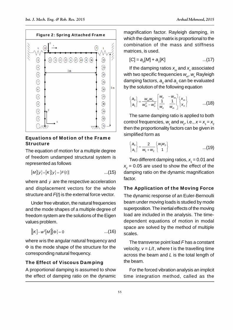
for column 1 is 90° and r for column 2 is 270°as shown in Figure 1. A spring is attached tothe frame at the column and beam conjunctionpoints in order to analyze the effect of thespring stiffness. Spring has a stiffness k in thex direction as shown in Figure 2.
The effect of springs on the dynamicresponse of the frame structure is investigated.The stiffness of the spring k is added tocolumn’s stiffness matrices as a constant termat the corresponding degree of freedom.
Figure 1: Modelling the Frame Elements
55
Int. J. Mech. Eng. & Rob. Res. 2015 Arshad Mehmood, 2015
Equations of Motion of the FrameStructureThe equation of motion for a multiple degreeof freedom undamped structural system isrepresented as follows
tFyKyM ...(15)
where and y are the respective accelerationand displacement vectors for the wholestructure and F(t) is the external force vector.
Under free vibration, the natural frequenciesand the mode shapes of a multiple degree offreedom system are the solutions of the Eigenvalues problem.
02 MK ...(16)
where is the angular natural frequency and is the mode shape of the structure for thecorresponding natural frequency.
The Effect of Viscous DampingA proportional damping is assumed to showthe effect of damping ratio on the dynamic
magnification factor. Rayleigh damping, inwhich the damping matrix is proportional to thecombination of the mass and stiffnessmatrices, is used.
[C] = a0[M] + a1[K] ...(17)
If the damping ratios m and n associatedwith two specific frequencies m, n Rayleighdamping factors, a0 and a1 can be evaluatedby the solution of the following equation
n
m
mn
mn
nm
nm
aa
11
221
0...(18)
The same damping ratio is applied to bothcontrol frequencies, 1 and 2, i.e., = 1 = 2
then the proportionality factors can be given insimplified form as
12 21
211
0 a
a...(19)
Two different damping ratios, 1 = 0.01 and2 = 0.05 are used to show the effect of thedamping ratio on the dynamic magnificationfactor.
The Application of the Moving ForceThe dynamic response of an Euler-Bernoullibeam under moving loads is studied by modesuperposition. The inertial effects of the movingload are included in the analysis. The time-dependent equations of motion in modalspace are solved by the method of multiplescales.
The transverse point load F has a constantvelocity, v = L/, where t is the travelling timeacross the beam and L is the total length ofthe beam.
For the forced vibration analysis an implicittime integration method, called as the
Figure 2: Spring Attached Frame

56
Int. J. Mech. Eng. & Rob. Res. 2015 Arshad Mehmood, 2015
Newmark integration method is used with theintegration parameters =1/4 and ϒ =1/2,which lead to constant-average accelerationapproximation. The time step is chosen as t= T20/20 during the beam vibration analysis inorder to ensure that all the 20 modes contributeto the dynamic response, where T20 is theperiod of the 20th natural mode of the structure.
The time history of the nodal force in thetransverse direction is given in Figure 3. Thetime for the load to arrive ith node, = xi/v,where xi is the location of ith node. The nodalforce on the ith node, Fi = 0 except -1 < t <+1.The force is applied all the nodes accordingto Figure 4. Moment effect of the force isignored, only vertical degree of freedom isaffected by this force. The Simple method inwhich Mi = 0 at any time is used for thecalculation of the dynamic responses. A non-dimensional velocity parameter a is used as = T1/, where Ti is the period of the firstnatural frequency of the beam.
Results of the Dynamic Analysis ofFrame StructureFigure 4 shows the first three mode shapes ofthe frame and spring attached frame (k2).Attaching a spring to the frame at theconjunction points of the beam and columnsmakes the frame more rigid and shifts themode shapes of the frame structure up.Generally, the first mode of vibration is the oneof primary interest. The first mode usually hasthe largest contribution to the structure’smotion. The period of this mode is the longest.(Shortest natural frequency = first eigenvecto.
Figure 10 the effect of a on the dynamicmagnification factor of column 2 for normal andspring attached frame at different nodes.
Figure 4: First Three Mode Shape of theFrame and Spring Attached Frame (K2)
Framef1 = 7.537 Hz
Spring Attached k2f1 = 29.74 Hz
Framef2 = 29.74 Hz
Spring Attached k2f2 = 42.26 Hz
Framef3 = 48.52 Hz
Spring Attached k2f3 = 52.61 Hz
Figure 3: Moving Load Time Historyfor the ith Node
57
Int. J. Mech. Eng. & Rob. Res. 2015 Arshad Mehmood, 2015
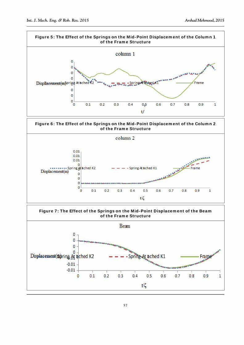
Figure 5: The Effect of the Springs on the Mid-Point Displacement of the Column 1of the Frame Structure
Figure 6: The Effect of the Springs on the Mid-Point Displacement of the Column 2of the Frame Structure
Figure 7: The Effect of the Springs on the Mid-Point Displacement of the Beamof the Frame Structure

58
Int. J. Mech. Eng. & Rob. Res. 2015 Arshad Mehmood, 2015
Figure 8: The Effect of a on the Dynamic Magnification Factor of Column 1 for Normaland Spring Attached Frame at Different Node
Figure 9: The Effect of a on the Dynamic Magnification Factor of Beam for Normaland Spring Attached Frame at Different Nodes
Figure 10: The Effect of a on the Dynamic Magnification Factor of Column 2 for Normaland Spring Attached Frame at Different Nodes

59
Int. J. Mech. Eng. & Rob. Res. 2015 Arshad Mehmood, 2015
Figures 5, 6, and 7 show the effect of theassumed springs stiffness (Ks) on the mid-point displacements of beam and columns ofa Frame structure. Three critical load speedsshown in Figures 8, 9 and 10 are consideredfor columns and beam. v = 4.522 m/s forcolumn 1 ( = 0.6), v = 34.67 m/s for beam (= 4.6), v = 45.22 m/s for column 2 ( = 6).Figure 5 shows that springs have more effecton the dynamic response of the mid-point ofcolumn 1 for the critical load speed and reducethe maximum dynamic displacements. On theother hand, springs have no contribution forbeam displacements as shown in Figure 6 andalso no noteworthy contribution for the mid-point displacement of column 2 as shown inFigure 7.
Figures 8-10 shows the effect of a valueson the dynamic magnification factor fordifferent nodes of a normal and spring attachedframe. Dynamic magnification factors arecalculated for frame structure as calculated forbeam. Dd is the ratio of the maximum dynamicdisplacement to the static displacement at theconsidered node. The static displacements forall the nodes of the beam and columns of theframe are calculated when the force acting onthe mid-point of the beam. There is nonoteworthy difference between frame andspring attached frame static displacementsexcept conjunction points. Figures 8-10 alsoshow the contribution of springs to Dd. It canbe said that for small a values ( < 1) springsare very effective for all nodes. In this interval,higher Dd values are obtained with increasingspring stiffness. Figures 8-10 show the Dd
values only when the moving load is on thebeam, so the interpretations are based on thissituation. The maximum Dd values occur in the
neighborhood of = 6 for nodes 2-5. Theattachment of the spring causes higher Dd
values in the middle speed region. Lower Dd
values are obtained with increasing springstiffness in this region. The maximum Dd
values for nodes 6-11 are observed close to = 0.6. The springs are very effectiveespecially in this low speed region, but higherDd values are obtained with increasing springstiffness in this interval. For beam (nodes 12-21) not a noteworthy difference is observedboth by attaching a spring or increasing springstiffness. The maximum Dd occurs at = 4.5for the mid-point of the beam. Similar to column1, two critical moving load speeds areobserved for column 2, =1 and = 6. Thesprings have no contribution to the Dd valuesfor both beam and columns at high speedregion ( > 10). Lower Dd values are obtainedby attaching spring for column 2 in the middlespeed region.
Table 1 Dynamic magnification factors forthe mid-points of the beam and columns of theframe and spring attached frame for different values. (* values which makes Dd maximumwhen the moving load is on the beam.
Effect of the Rayleigh DampingDynamic analyses are performed to show theeffect of the Rayleigh damping on themagnification factors of beam and framestructures. A description of a mechanicalstructure requires knowledge of the geometry,boundary conditions and material properties.The mass and stiffness matrices of a structurewith complicated geometry, boundaryconditions and material properties can beobtained experimentally or numerically (forexample, using the finite-element method).Unfortunately, present knowledge of damping

60
Int. J. Mech. Eng. & Rob. Res. 2015 Arshad Mehmood, 2015
does not allow us to obtain the damping matrixlike the mass and stiffness matrices forcomplicated systems. For this reason weconsider simple systems for which geometry,boundary conditions and material propertiesare easy to determine.
Figure 11 shows the effect of damping ratio on the magnification factor of a clamped-clamped beam. The maximum Dd value(1.632), which is observed at = 1.02 for theundamped case is recorded at = 1 (Dd =1.608) for = 0.01 and at = 0.97 (Dd =1.524) for = 0.05. Dd values are decreasedwith increasing damping ratio as expected andthe time at which the maximum Dd occurs shiftsleft with increasing damping ratio.
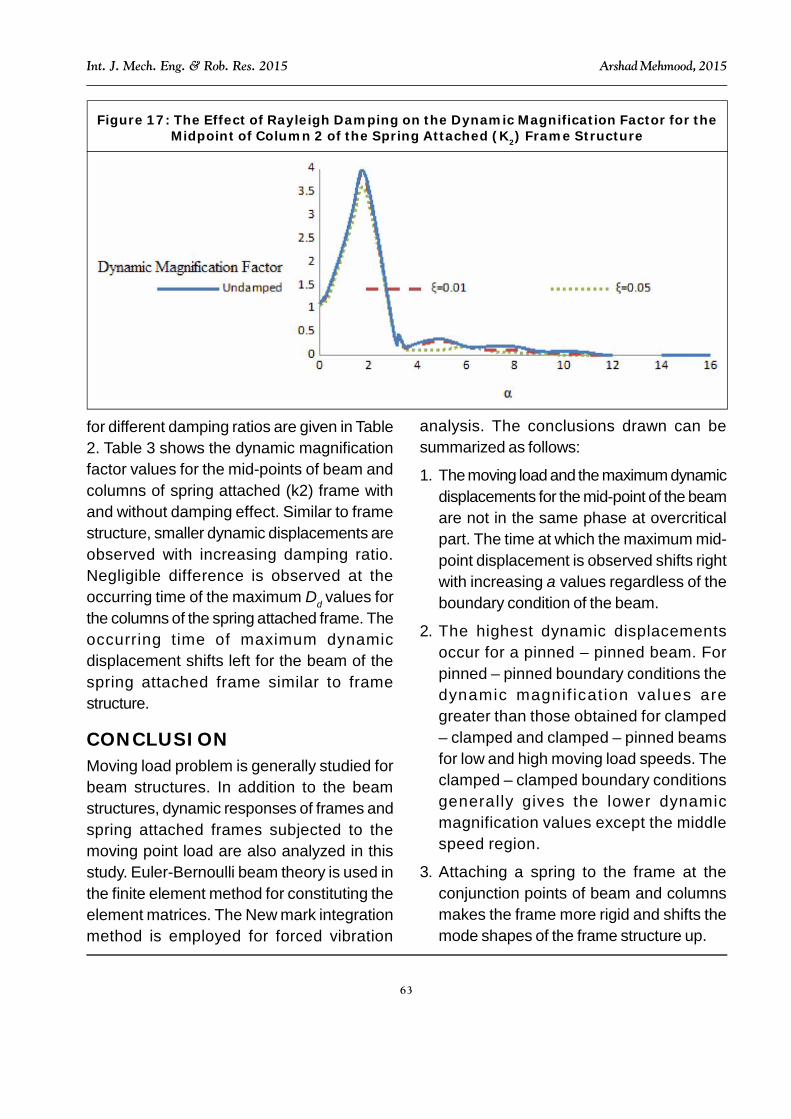
Figures 12-17 show the effect of theRayleigh damping on the dynamicmagnification factor for the mid-point of bothcolumns and beam of frame and springattached (k2) frame. The maximum Dd valuesfor the mid-points of columns and beam of theframe are; for = 0.01, at = 6.1 (Dd = 1.849)for column 1, at = 4.4 (Dd = 1.534) for beamand at = 6.1 (Dd = 3.595) for column 2.Similarly the maximum Dd values are observedat = 0.7 (Dd = 1.691) for column 1, at = 4.2(Dd = 1.468) for beam and at = 6.1 (Dd =3.172) for column 2 for the damping ratio =0.05. Lower Dd values are observed withincreasing damping ratio.
The time at which the maximum Dd valuesoccur shifts left for the mid-point of the beamof the frame with increasing damping ratio, butthe maximum Dd values are obtained withhigher values for the columns of the frame withincreasing damping ratio. The dynamicmagnification factors for the frame structure
0.2 1.291 1.113 1.121
0.4 1.572 1.206 1.179
0.6 1.804 1.214 1.203
1.0 1.955 1.284 1.209
1.5 1.873 1.470 1.424
1.9 1.821 1.421 1.419
2.0 1.730 1.372 1.504
4.0 3.123 2.754 3.628
4.5 3.388 3.025 3.312
6.0 3.710 3.358 3.630
7.0 3.467 3.132 3.343
8.0 2.77o 2.571 2.486
10.0 1.433 1.370 1.256
12.0 0.614 0.609 0.598
14.0 0.219 0.215 0.209
16.0 0.230 0.226 0.220
Table 2: Maximum Dd Values for the Mid-Points of the Columns and Beam of the
Frame with the Effect of Damping
Frame (Column 2)
Frame SpringAttached (k1)
SpringAttached (k2)
Table 3: Maximum Dd Values for the Mid-Points of the Columns and Beam of theSpring Attached (k2) Frame with the
Effect of DampingUndamped
Quantity Dd
Column 1 2.016 1.6Beam 1.550 1.2Column 2 3.635 1.5
= 0.01Quantity Dd
Column 1 1.969 1.6Beam 1.532 1.1Column 2 3.538 1.5
= 0.05Quantity Dd
Column 1 1.795 1.6Beam 1.465 1.1Column 2 3.189 1.5

61
Int. J. Mech. Eng. & Rob. Res. 2015 Arshad Mehmood, 2015
Figure 11: The Effect of Rayleigh Damping on the Magnification Factor of Clamped-Clamped Beam
Figure 12: The Effect of Rayleigh Damping on the Dynamic Magnification Factor for theMidpoint of Column 1 of the Frame Structure
Figure 13: The Effect of Rayleigh Damping on the Dynamic Magnification Factor for theMidpoint of Beam of the Frame Structure

62
Int. J. Mech. Eng. & Rob. Res. 2015 Arshad Mehmood, 2015
Figure 14: The Effect of Rayleigh Damping on the Dynamic Magnification Factor for theMidpoint of Column 2 of the Frame Structure
Figure 15: The Effect of Rayleigh Damping on the Dynamic Magnification Factor for theMidpoint of Column 1 of the Spring Attached (k2) Frame Structure
Figure 16: The Effect of Rayleigh Damping on the Dynamic Magnification Factor for theMidpoint of Beam of the Spring Attached (k2) Frame Structure
63
Int. J. Mech. Eng. & Rob. Res. 2015 Arshad Mehmood, 2015
Figure 17: The Effect of Rayleigh Damping on the Dynamic Magnification Factor for theMidpoint of Column 2 of the Spring Attached (K2) Frame Structure
for different damping ratios are given in Table2. Table 3 shows the dynamic magnificationfactor values for the mid-points of beam andcolumns of spring attached (k2) frame withand without damping effect. Similar to framestructure, smaller dynamic displacements areobserved with increasing damping ratio.Negligible difference is observed at theoccurring time of the maximum Dd values forthe columns of the spring attached frame. Theoccurring time of maximum dynamicdisplacement shifts left for the beam of thespring attached frame similar to framestructure.
CONCLUSIONMoving load problem is generally studied forbeam structures. In addition to the beamstructures, dynamic responses of frames andspring attached frames subjected to themoving point load are also analyzed in thisstudy. Euler-Bernoulli beam theory is used inthe finite element method for constituting theelement matrices. The New mark integrationmethod is employed for forced vibration
analysis. The conclusions drawn can besummarized as follows:
1. The moving load and the maximum dynamicdisplacements for the mid-point of the beamare not in the same phase at overcriticalpart. The time at which the maximum mid-point displacement is observed shifts rightwith increasing values regardless of theboundary condition of the beam.
2. The highest dynamic displacementsoccur for a pinned – pinned beam. Forpinned – pinned boundary conditions thedynamic magnif icat ion values aregreater than those obtained for clamped– clamped and clamped – pinned beamsfor low and high moving load speeds. Theclamped – clamped boundary conditionsgenerally gives the lower dynamicmagnification values except the middlespeed region.
3. Attaching a spring to the frame at theconjunction points of beam and columnsmakes the frame more rigid and shifts themode shapes of the frame structure up.
64
Int. J. Mech. Eng. & Rob. Res. 2015 Arshad Mehmood, 2015
4. A longer beam implies a smaller first naturalfrequency for frame structure; similarlylonger columns imply smaller naturalfrequencies.
5. With lower values ( < 1) springs are veryeffective for all nodes. In this interval, higherDd values are obtained with increasingspring stiffness. In the middle and highspeed region, attaching a spring to theframe is not an advisable solution due tothe increasing Dd values.
6. Maximum Dd occurs after the moving loadleft the beam for both columns and beam ofthe frame structure when the value isgreater than some critical values.
7. Lower Dd values are observed withincreasing damping ratio for a clamped-clamped beam. The occurring time ofmaximum dynamic displacement shifts leftwith increasing damping ratio.
8. Maximum Dd values are observed atsmaller values both for the beam of theframe and spring attached frame withincreasing damping ratio.
REFERENCES1. Biggs J M (1982), “Introduction to
Structural Dynamics”, McGraw-Hill, NewYork.
2. Bilello C and Bergman L A (2004),“Vibration of Damaged Beams Under aMoving Mass: Theory and ExperimentalValidation”, Journal of Sound andVibration, Vol. 274, pp. 567-582.
3. Chandrupatla R Tirupathi and BelegunduD Ashok (2002), Introduction to FiniteElements in Engineering, 3rd Edition.
4. Chen Y H, Huang Y H and Shih C T (2001),“Response of an Infinite TimoshenkoBeam on a Viscoelastic Foundation to aHarmonic Moving Load”, Journal ofSound and Vibration, Vol. 241, No. 5, pp.809-824.
5. Chopra Anil K (1995), Dynamics ofStructures, Prentice Hall, New Jersey.
6. Clough R W and Penzien J (1993),Dynamics of Structures, McGraw-Hill,New York.
7. Hanselman Duane C (2001), MasteringMatlab 6, Prentice Hall, Upper SaddleRiver, New Jersey.
8. Hong S W and Kim J W (1999), “ModalAnalyses of Multi Span TimoshenkoBeams Connected or Supported byResilient Joints with Damping”, Journalof Sound and Vibration, Vol. 227, No. 4,pp. 787-806.
9. Ichikawa M, Miyakawa Y and Matsuda A(2000), “Vibration Analysis of theContinuous Beam Subjected to a MovingMass”, Journal of Sound and Vibration,Vol. 230, No. 3, pp. 493-506.
10. Kadivar M H and Mohebpour S R (1998),“Finite Element Dynamic Analysis ofUnsymmetric Composite LaminatedBeams with Shear Effect and RotaryInertia Under the Action of Moving Loads”,Finite Elements in Analysis and Design,Vol. 29, pp. 259-273.
11. Newmark N (1959), “A Method ofComputation for Structural Dynamics”, J.Eng. Mech. Div. ASCE, pp. 67-94.
12. Oniszczuk Z (2003), “Forced TransverseVibrations of an Elastically Connected

65
Int. J. Mech. Eng. & Rob. Res. 2015 Arshad Mehmood, 2015
Complex Simply Supported Double-Beam System”, Journal of Sound andVibration, Vol. 264, pp. 273-286.
13. Rao Singiresu S (1995), MechanicalVibrations, Addison-Wesley PublishingCompany.
14. Wu J J, Whittaker A R and Cartmell M P(2001), “Dynamic Responses ofStructures to Moving Bodies Using
Combined Finite Element and AnalyticalMethods”, International Journal ofMechanical Sciences , Vol. 43,pp. 2555-2579.
15. Zibdeh H S and Hilal M A (2003),“Stochastic Vibration of LaminatedComposite Coated Beam Traversed bya Random Moving Load”, EngineeringStructures, Vol. 25, pp. 397-400.