Using Digital Potentiometers in Laser Diode Applications
29
Using Digital Potentiometers in Laser Diode Applications JC - 5/15/01 1 Using Digital Potentiometers in Laser Diode Applications
Transcript of Using Digital Potentiometers in Laser Diode Applications
Using Digital Potentiometers in Laser DiodeApplicationsJC - 5/15/01 1
Using Digital Potentiometers inLaser Diode Applications
Using Digital Potentiometers in Laser DiodeApplicationsJC - 5/15/01 2
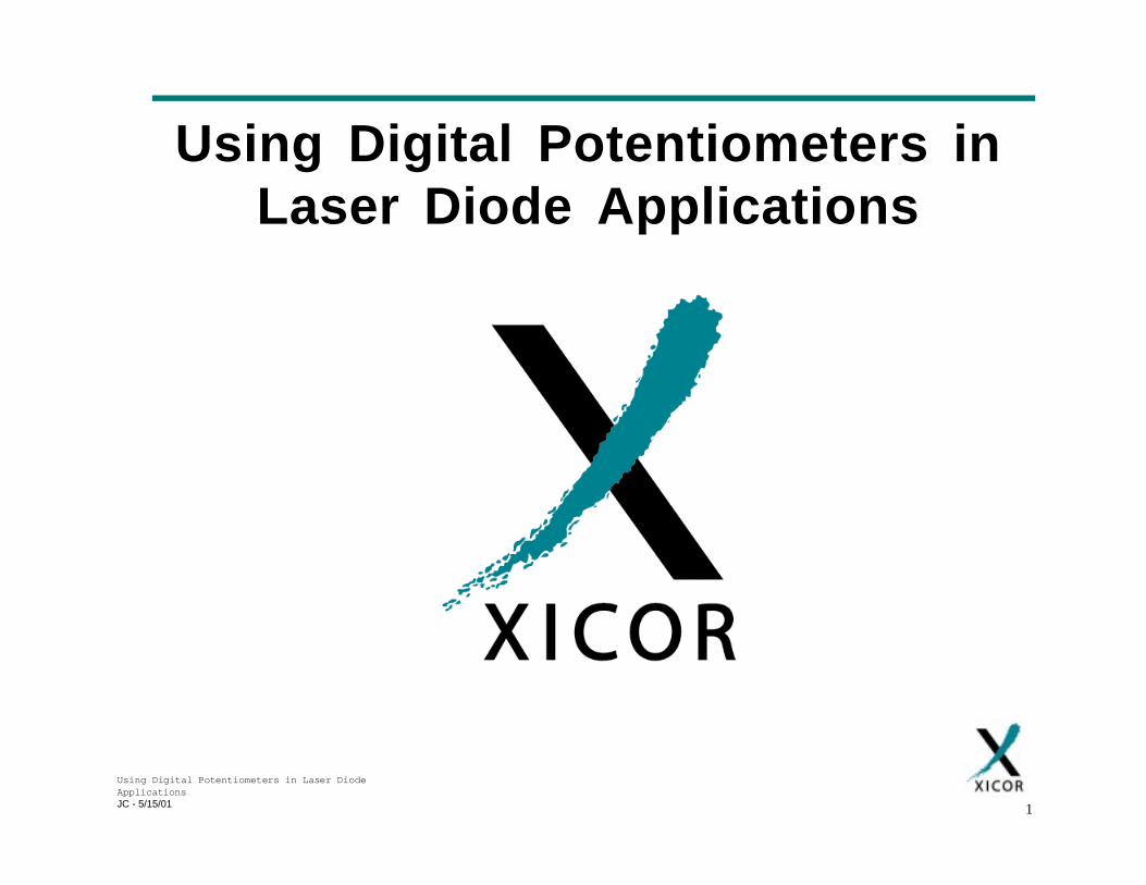
Introduction
• “Fiber Optic Communications”
– Transmission of voice / data using light via Optical Fiber
E/OModulation
E/ODemodulation(+ Re-timing)
Optical Fiber
SIGNAL IN
SIGNAL OUT
Repeater / Amp (Optical)
Using Digital Potentiometers in Laser DiodeApplicationsJC - 5/15/01 3
Introduction
• Benefits of fiber optic communications
– Fiber optic cable has lower losses than metallic lines• Longer distances with fewer repeaters
– Fiber optic cable has higher BW than metallic lines• Useful BW is in the order of 100s of GHz
• More data / voice channels per cable
– Fiber optic cable impervious to electrical interference
– Security

Using Digital Potentiometers in Laser DiodeApplicationsJC - 5/15/01 4
Focus on Digital Communications
NAME DATA RATE APPLICATION / COMMENTS
FOIRL / 10BaseFL 10Mb/s Small LAN - Office2km fiber runs
Fast Ethernet / 100BaseFX 10Mb/s100Mb/s
Medium LAN – Building400m – 2km fiber runs
Gigabit Ethernet (GE) 1Gb/s Medium LAN – Building25 – 500m fiber runs
Fibre Channel Standard(FCS)
133Mb/s – 4Gb/s High BW point-point serial link.Device-Station, Station-Station, SAN.
300m – 40km fiber runsFDDI 100Mb/s MAN, WAN
Up to 500 Stations per network.2 – 40 km fiber runs
ATM – with SONET/SDHPhysical Layer
155Mb/s. 622Mb/s (Medium - Long Haul) Telecom’s,B-ISDN, SONET, SDH
ATM – with other PhysicalLayers
Up to 2.5Gb/s Supported by optical network Physicallayers other than SONET / SDH.
• System Standard Examples
Using Digital Potentiometers in Laser DiodeApplicationsJC - 5/15/01 5
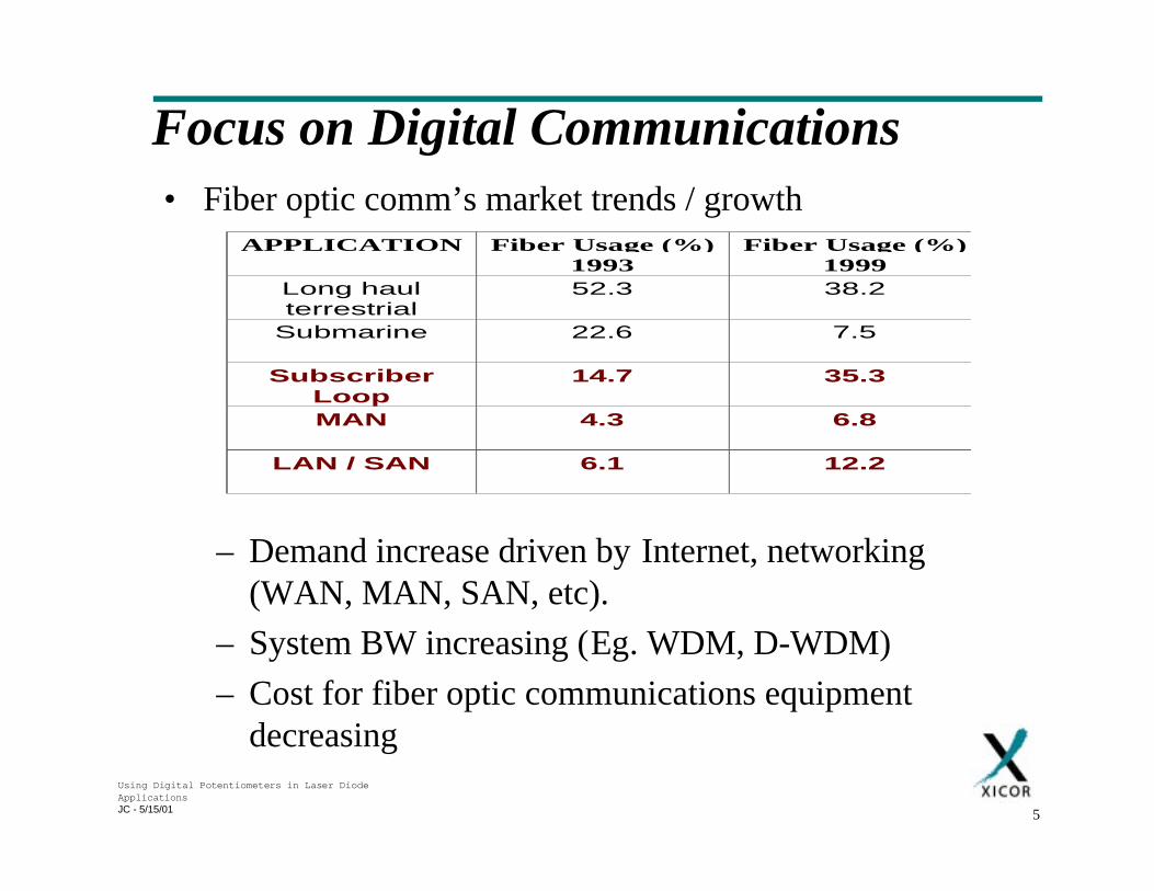
• Fiber optic comm’s market trends / growth
– Demand increase driven by Internet, networking(WAN, MAN, SAN, etc).
– System BW increasing (Eg. WDM, D-WDM)
– Cost for fiber optic communications equipmentdecreasing
Focus on Digital Communications
APPLICATION Fiber Usage (%)1993
Fiber Usage (%)1999
Long haulterrestrial
52.3 38.2
Submarine 22.6 7.5
SubscriberLoop
14.7 35.3
MAN 4.3 6.8
LAN / SAN 6.1 12.2
Using Digital Potentiometers in Laser DiodeApplicationsJC - 5/15/01 6
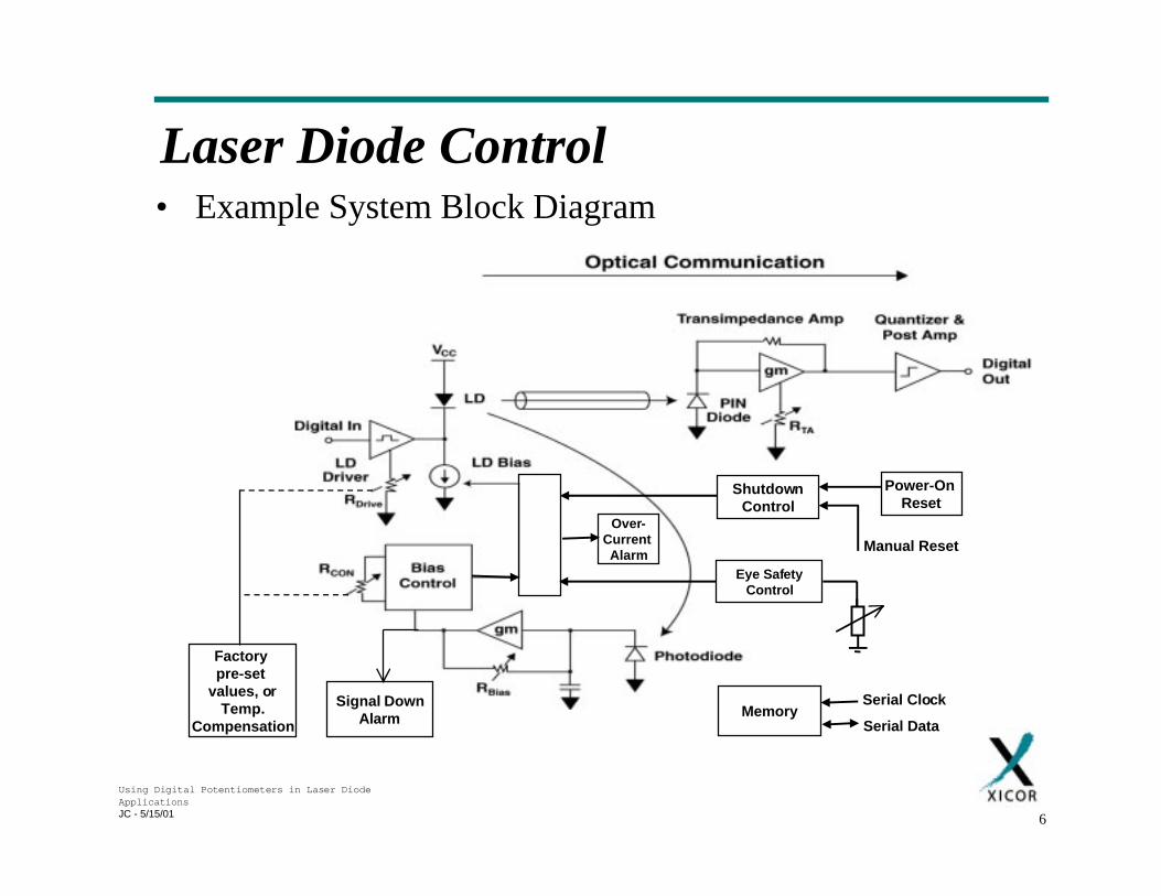
Laser Diode Control• Example System Block Diagram
Factory pre-set
values, orTemp.
Compensation
Signal DownAlarm
Over-Current Alarm
ShutdownControl
Power-On Reset
Manual Reset
Eye SafetyControl
MemorySerial Clock
Serial Data
Using Digital Potentiometers in Laser DiodeApplicationsJC - 5/15/01 7
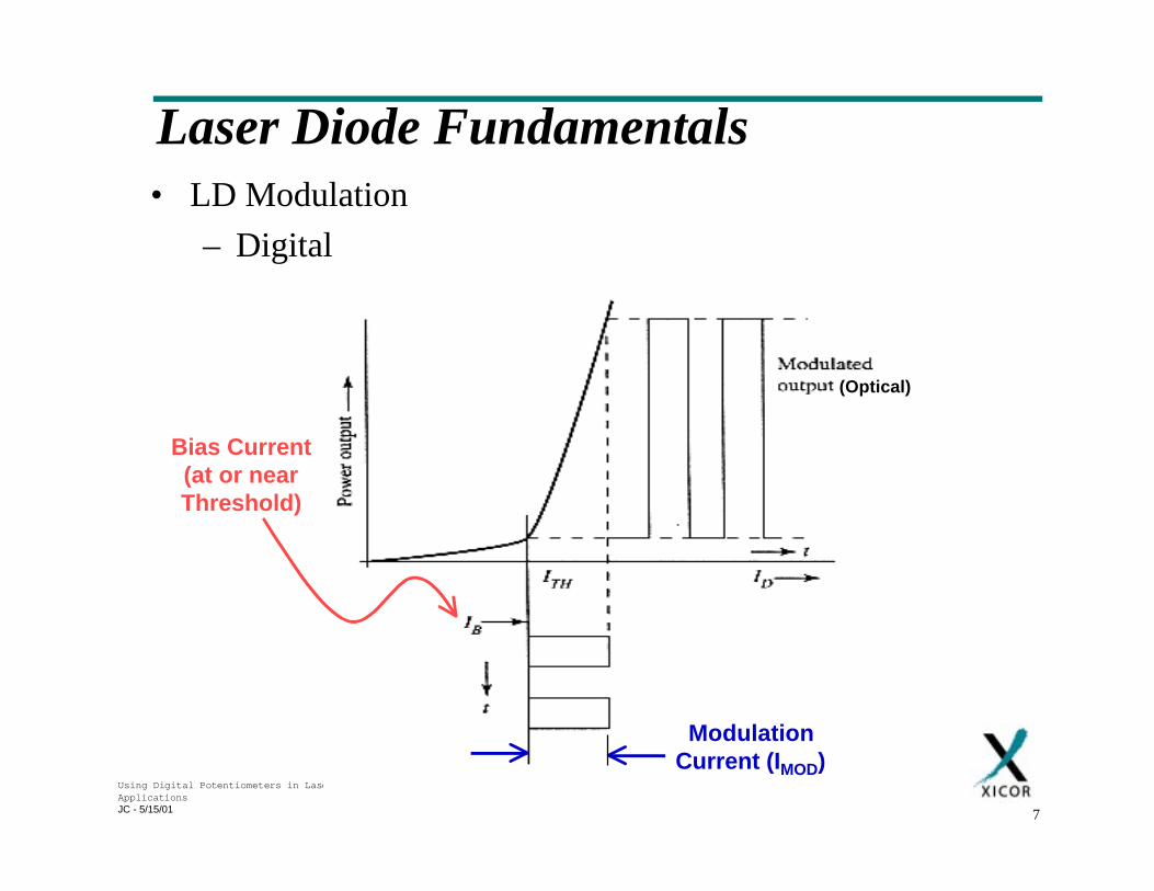
Laser Diode Fundamentals• LD Modulation
– Digital
ModulationCurrent (IMOD)
Bias Current (at or near Threshold)
(Optical)
Using Digital Potentiometers in Laser DiodeApplicationsJC - 5/15/01 8
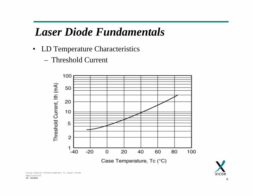
Laser Diode Fundamentals• LD Temperature Characteristics
– Threshold Current
Using Digital Potentiometers in Laser DiodeApplicationsJC - 5/15/01 9
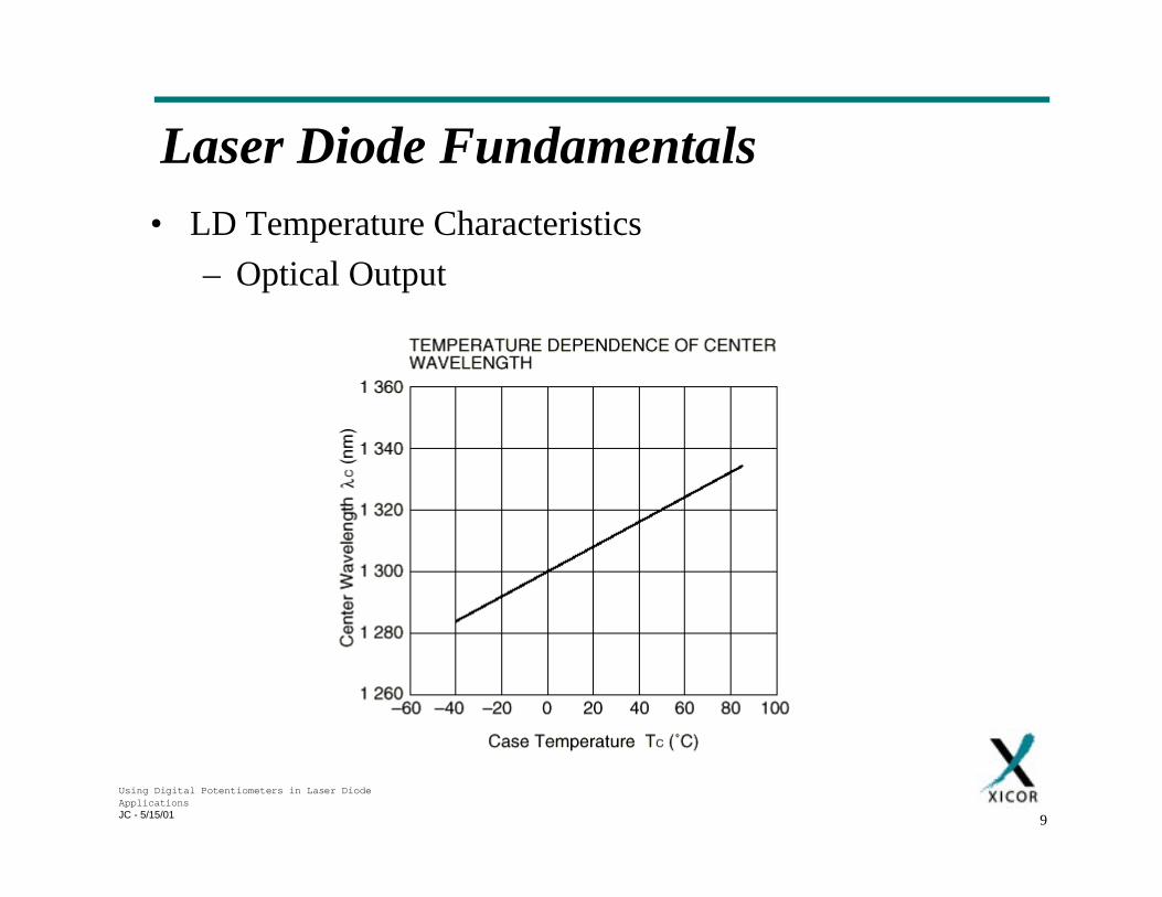
Laser Diode Fundamentals• LD Temperature Characteristics
– Optical Output
Using Digital Potentiometers in Laser DiodeApplicationsJC - 5/15/01 10
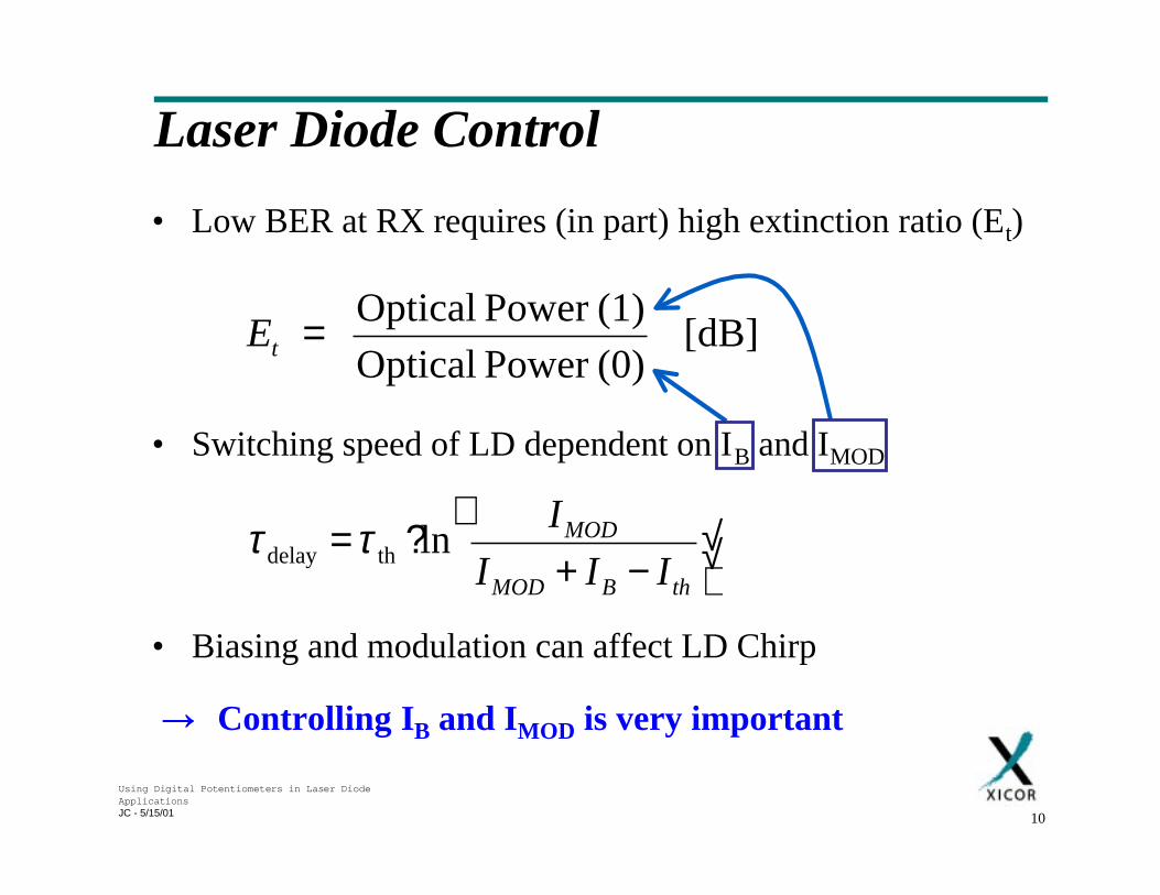
Laser Diode Control
• Low BER at RX requires (in part) high extinction ratio (Et)
• Switching speed of LD dependent on IB and IMOD
• Biasing and modulation can affect LD Chirp
→ Controlling IB and IMOD is very important
[dB] (0)Power Optical(1)Power Optical
=tE
√√↵
−+
?=thBMOD
MOD
III
Iln thdelay ττ
Using Digital Potentiometers in Laser DiodeApplicationsJC - 5/15/01 11
Laser Diode Control• Laser diode control requirements
– Set max value for IMOD
• Avoids damage to LD due to excessive current
• Maximize extinction ratio
– Set value for IB
• Minimize τdelay , Laser Chirp, etc.
• Maximize Extinction Ratio
– Maintain constant temperature• Centre wavelength shifts with temperature.
– APC maintains a constant average optical power output by varyingIMOD and / or IB dynamically
• Compensates for changes in LD characteristics due to temp.variations, aging, etc.
• Maintains high extinction ratio
• Minimize system BER
Using Digital Potentiometers in Laser DiodeApplicationsJC - 5/15/01 12
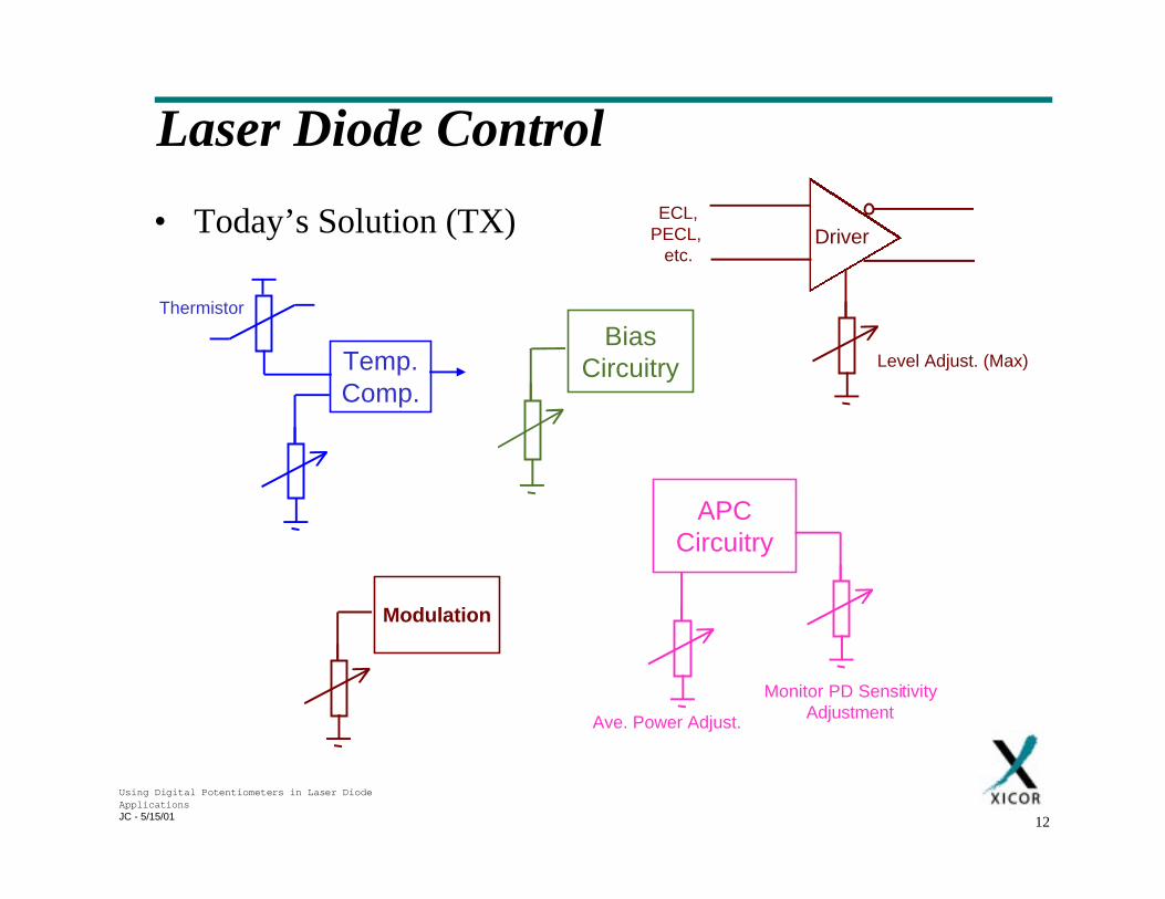
Laser Diode Control
• Today’s Solution (TX) DriverECL,
PECL, etc.
Level Adjust. (Max)
APCCircuitry
Monitor PD SensitivityAdjustmentAve. Power Adjust.
BiasCircuitryTemp.
Comp.
Thermistor
Modulation
Using Digital Potentiometers in Laser DiodeApplicationsJC - 5/15/01 13
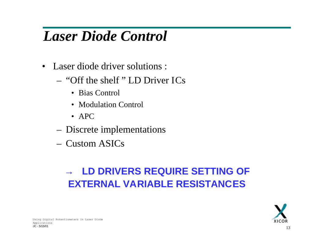
Laser Diode Control
• Laser diode driver solutions :
– “Off the shelf ” LD Driver ICs• Bias Control
• Modulation Control
• APC
– Discrete implementations
– Custom ASICs
→ LD DRIVERS REQUIRE SETTING OFEXTERNAL VARIABLE RESISTANCES
Using Digital Potentiometers in Laser DiodeApplicationsJC - 5/15/01 14
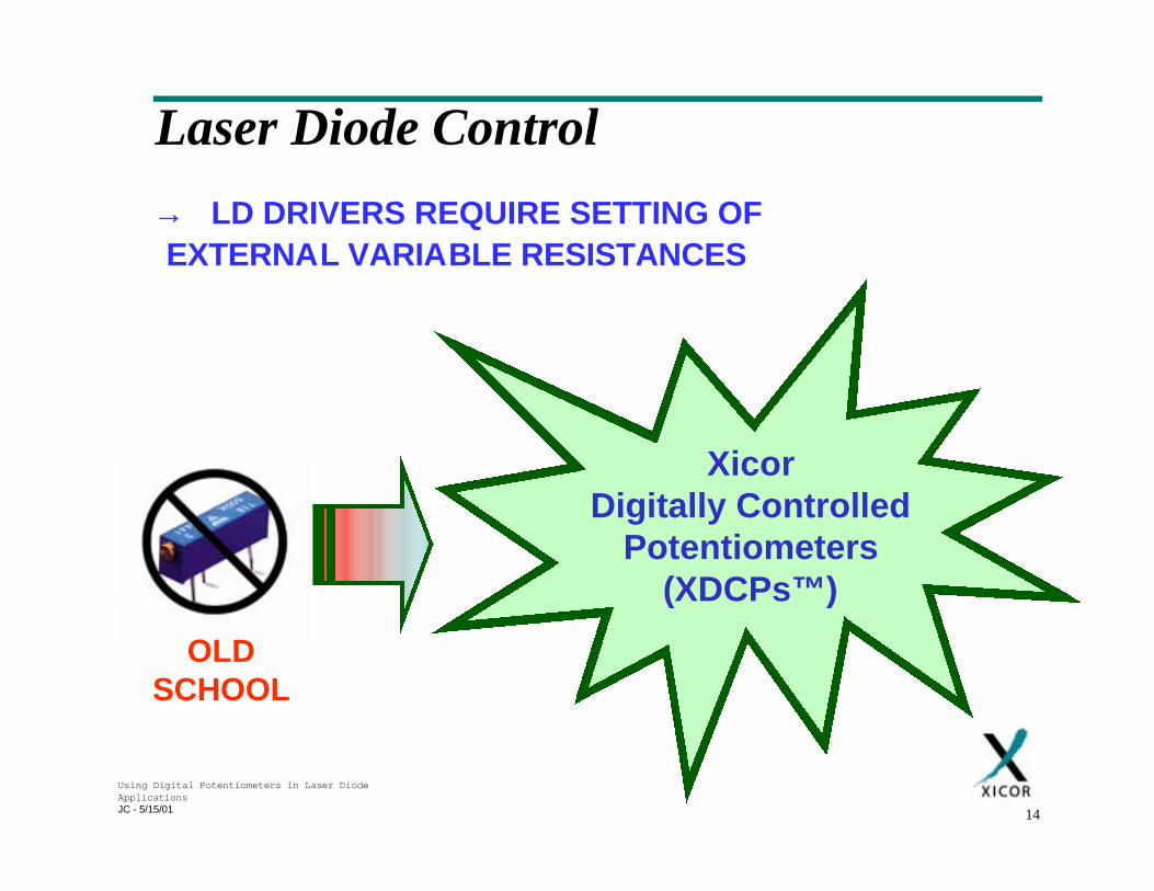
XicorDigitally Controlled
Potentiometers(XDCPs™)
Laser Diode Control
→ LD DRIVERS REQUIRE SETTING OFEXTERNAL VARIABLE RESISTANCES
OLDSCHOOL
Using Digital Potentiometers in Laser DiodeApplicationsJC - 5/15/01 15
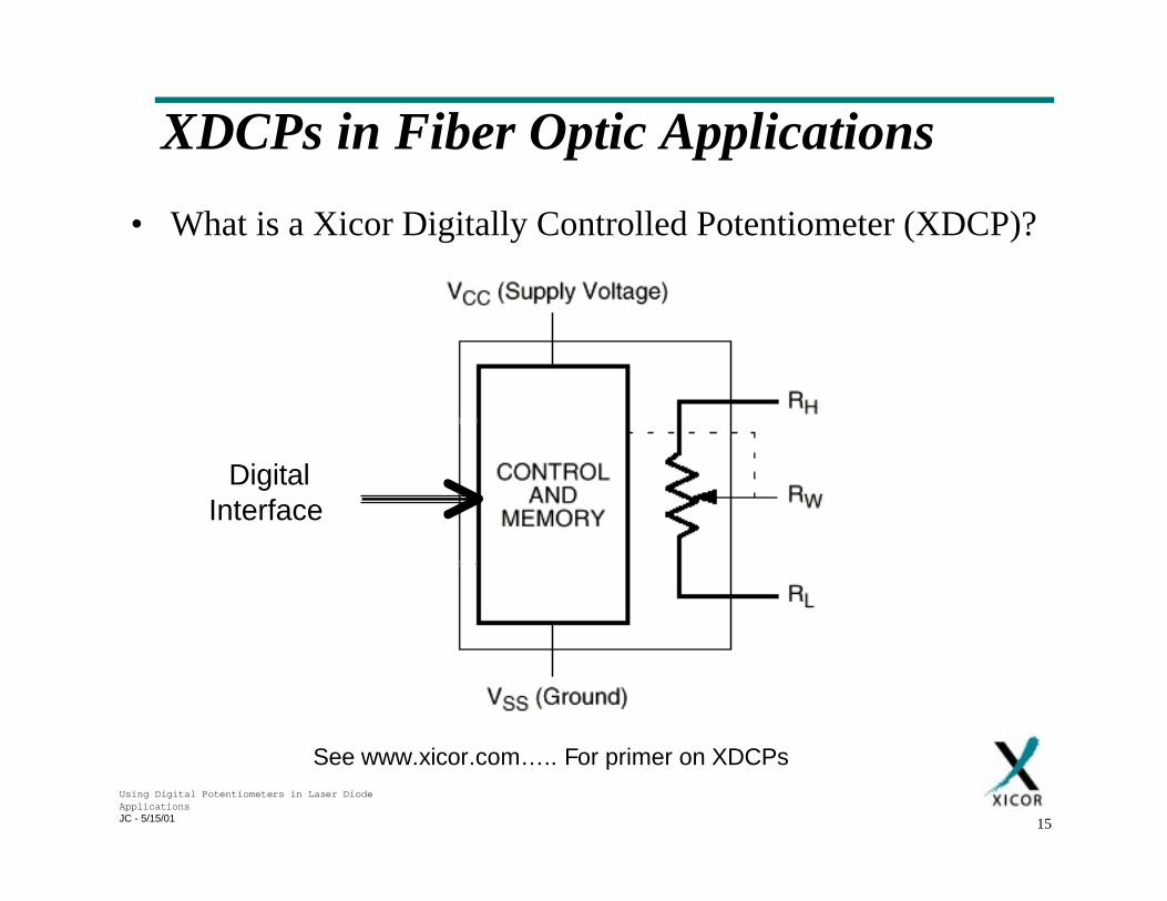
XDCPs in Fiber Optic Applications
• What is a Xicor Digitally Controlled Potentiometer (XDCP)?
DigitalInterface
See www.xicor.com….. For primer on XDCPs
Using Digital Potentiometers in Laser DiodeApplicationsJC - 5/15/01 16
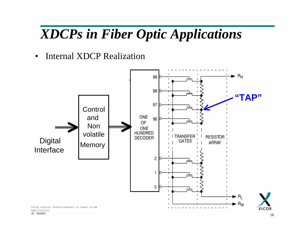
XDCPs in Fiber Optic Applications
• Internal XDCP Realization
DigitalInterface
Controland Non
volatile
Memory
“TAP”
Using Digital Potentiometers in Laser DiodeApplicationsJC - 5/15/01 17
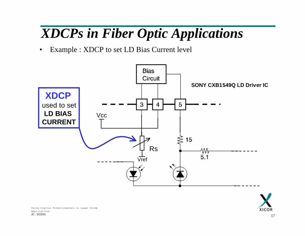
XDCPs in Fiber Optic Applications• Example : XDCP to set LD Bias Current level
Vcc
Vref
XDCP
used to setLD BIAS
CURRENT
Rs
SONY CXB1549Q LD Driver IC
Using Digital Potentiometers in Laser DiodeApplicationsJC - 5/15/01 18
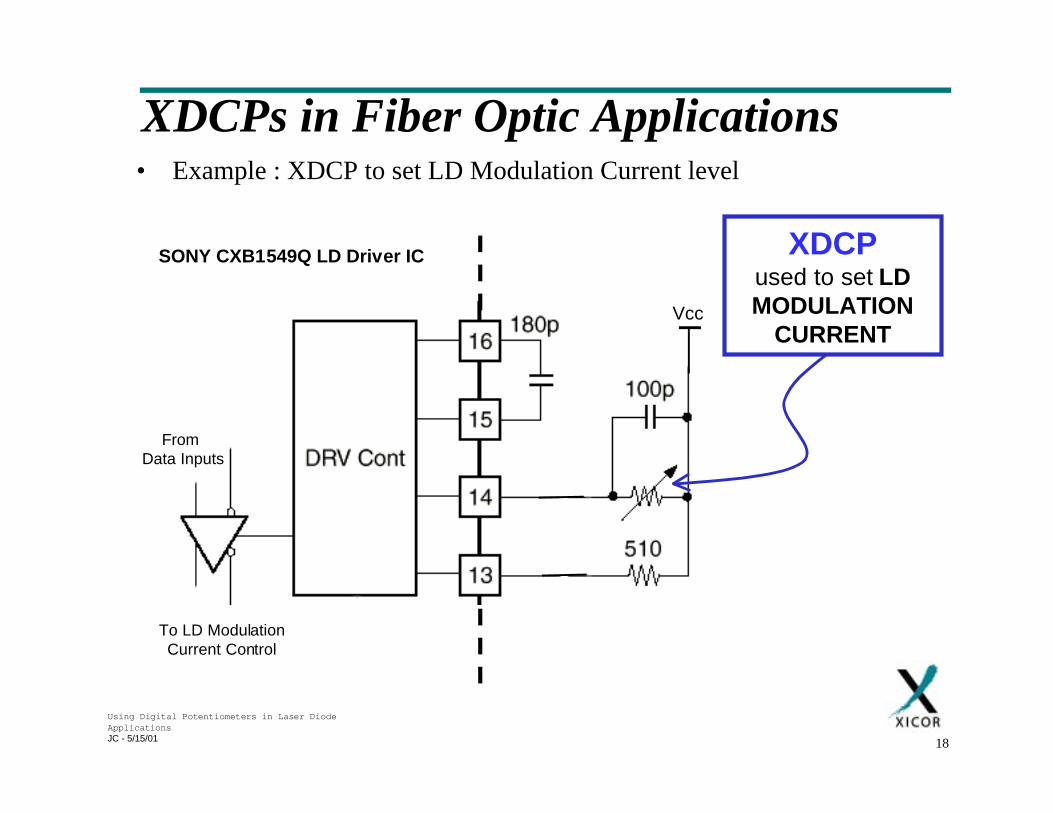
XDCPs in Fiber Optic Applications• Example : XDCP to set LD Modulation Current level
XDCPused to set LDMODULATION
CURRENT
SONY CXB1549Q LD Driver IC
Vcc
From Data Inputs
To LD ModulationCurrent Control
Using Digital Potentiometers in Laser DiodeApplicationsJC - 5/15/01 19
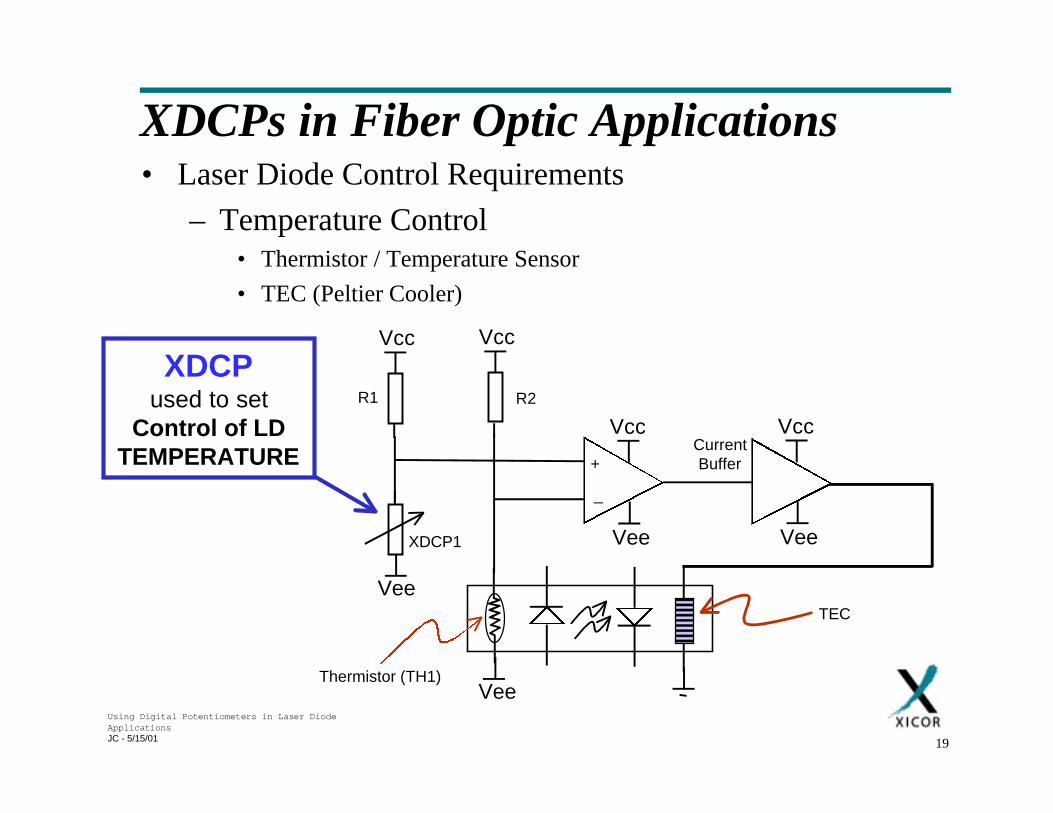
XDCPs in Fiber Optic Applications• Laser Diode Control Requirements
– Temperature Control• Thermistor / Temperature Sensor
• TEC (Peltier Cooler)
R1
+
_
Vcc
Vcc
Vee
Vcc
Vee
Vee
CurrentBuffer
Vcc
Vee
R2
XDCP1
Thermistor (TH1)
TEC
XDCPused to set
Control of LDTEMPERATURE
Using Digital Potentiometers in Laser DiodeApplicationsJC - 5/15/01 20
XDCPs in Fiber Optic Applications
• XDCP used to set LD operating levels– Simple set-and-forget functionality
• Nonvolatile memory and control eliminates need for uC
• Eliminates need for redundant EEPROM
– Reliability over mechanical solutions• No mechanical wear
– Shock proof
– Moisture proof
– Dust proof
Using Digital Potentiometers in Laser DiodeApplicationsJC - 5/15/01 21
XDCPs in Fiber Optic Applications
• XDCP used to set LD operating levels– Repeatable R settings
– Standard semiconductor reliability
– Tamper-proof• User cannot use simple screwdriver cannot change LD bias !
– Low cost of ownership• Automated adjustment
– Saves money in test and calibration
• Fast adjustment
• Eliminates human error
Using Digital Potentiometers in Laser DiodeApplicationsJC - 5/15/01 22
XDCPs in Fiber Optic Applications
• Power supply requirements
– Single supply devices• 2.7V to 5.5V operation
– Other supply options
• Range of digital iInterfaces
– 2-wire
– SPI
– 3-Wire UP/DOWN
– PushPot
Using Digital Potentiometers in Laser DiodeApplicationsJC - 5/15/01 23
XDCPs in Fiber Optic Applications
• Taps
– 16, 32, 64, 100, 256 taps
– 1024 taps (E.S. Available End Q2’00)
– Single, dual and quad devices
• Temperature co-efficient (T/C)
– Typical ±300ppm / °C
– Methods exist to shift T/C dependency
– Use as V divider → Ratiometric T/C = ±20ppm / °C
Using Digital Potentiometers in Laser DiodeApplicationsJC - 5/15/01 24
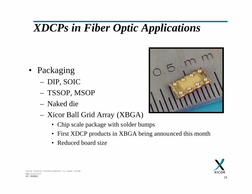
XDCPs in Fiber Optic Applications
• Packaging– DIP, SOIC
– TSSOP, MSOP
– Naked die
– Xicor Ball Grid Array (XBGA)• Chip scale package with solder bumps
• First XDCP products in XBGA being announced this month
• Reduced board size
Using Digital Potentiometers in Laser DiodeApplicationsJC - 5/15/01 25
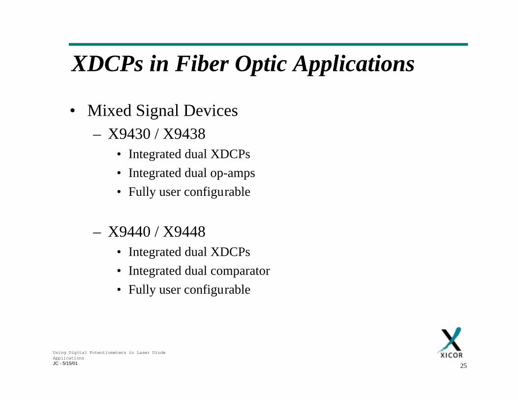
XDCPs in Fiber Optic Applications
• Mixed Signal Devices– X9430 / X9438
• Integrated dual XDCPs
• Integrated dual op-amps
• Fully user configurable
– X9440 / X9448• Integrated dual XDCPs
• Integrated dual comparator
• Fully user configurable
Using Digital Potentiometers in Laser DiodeApplicationsJC - 5/15/01 26
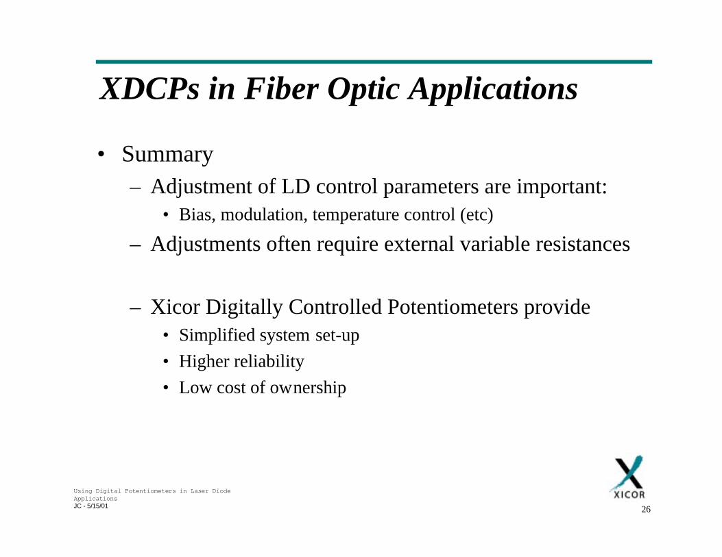
XDCPs in Fiber Optic Applications
• Summary– Adjustment of LD control parameters are important:
• Bias, modulation, temperature control (etc)
– Adjustments often require external variable resistances
– Xicor Digitally Controlled Potentiometers provide• Simplified system set-up
• Higher reliability
• Low cost of ownership
Using Digital Potentiometers in Laser DiodeApplicationsJC - 5/15/01 27
XDCPs in Fiber Optic Applications
• Summary
XDCP is the
control device of choice in Fiber Optic Applications
Using Digital Potentiometers in Laser DiodeApplicationsJC - 5/15/01 28
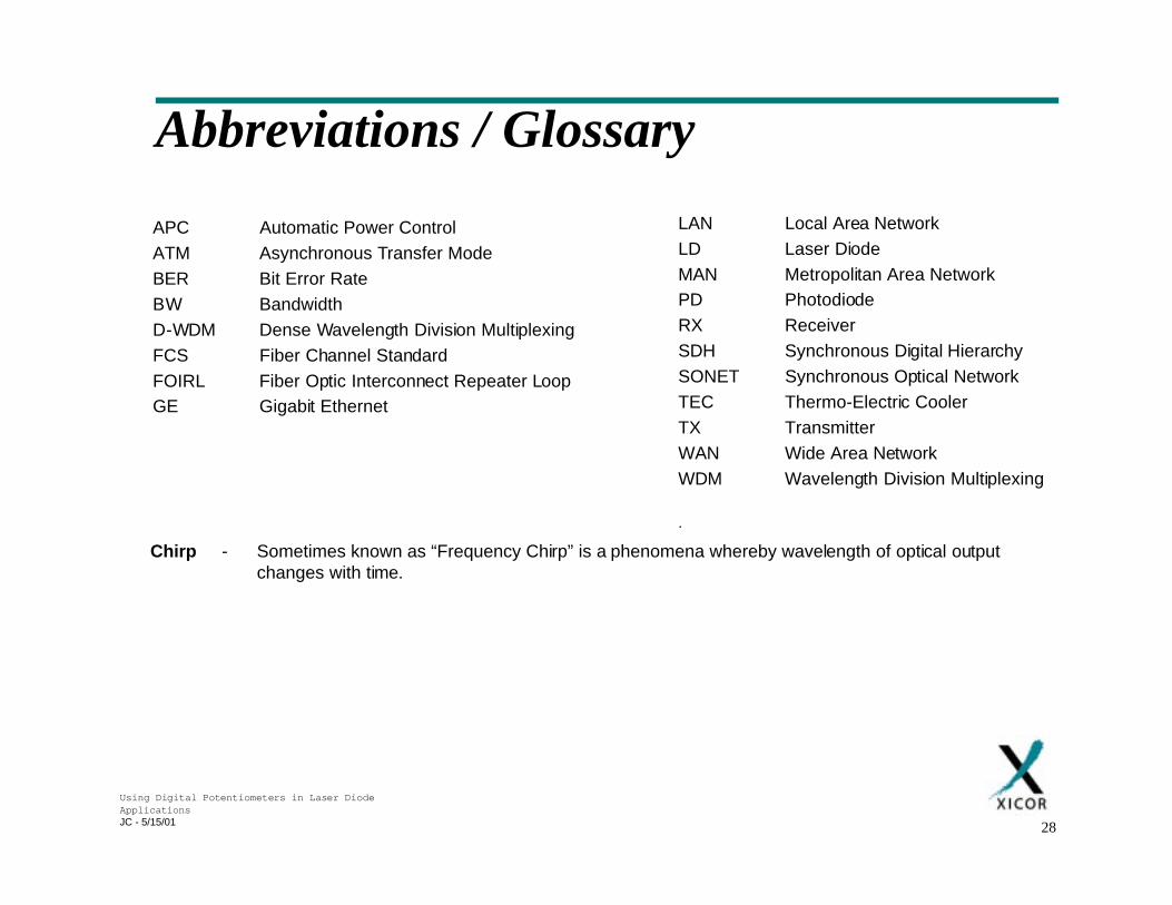
Abbreviations / Glossary
APC Automatic Power Control
ATM Asynchronous Transfer Mode
BER Bit Error Rate
BW Bandwidth
D-WDM Dense Wavelength Division Multiplexing
FCS Fiber Channel Standard
FOIRL Fiber Optic Interconnect Repeater Loop
GE Gigabit Ethernet
LAN Local Area Network
LD Laser Diode
MAN Metropolitan Area Network
PD Photodiode
RX Receiver
SDH Synchronous Digital Hierarchy
SONET Synchronous Optical Network
TEC Thermo-Electric Cooler
TX Transmitter
WAN Wide Area Network
WDM Wavelength Division Multiplexing
.
Chirp - Sometimes known as “Frequency Chirp” is a phenomena whereby wavelength of optical outputchanges with time.
Using Digital Potentiometers in Laser DiodeApplicationsJC - 5/15/01 29
Bibliography• Streetman B.G., 1990. Solid State Electronic Components. NJ, USA : Prentice
Hall.
• DeCusatis C., Maas E., Clement D.P., Lasky R.C., 1998. Handbook of FiberOptic Data Communications. London UK : Academic Press.
• Palais J.C., 1998. Fiber Optic Communicaions 4th Ed. N.J. USA : PrenticeHall International.
• Pedrotti K., High Speed Circuits for Lightwave Communications.International Journal of High Speed Electronics and Systems, Vol. 9, No. 2(1998), pp 313-346.
• Yamashita K., Miyake T., Cheap Optical Superhighway Will Reach JapaneseHomes. Nikkei Electronics Asia, October 1998, pp 35 - 40.