USING COMPUTER POWER SUPPLIES ON MODEL … COMPUTER POWER SUPPLIES ON MODEL RAILROADS ... Model...
19
USING COMPUTER POWER SUPPLIES ON MODEL RAILROADS by Jerry Hansz Model railroads need power other than for track/train operation. Buildings need lights, switch machines use voltage, crossing gates and signals don’t run on air! On the Santa Fe Central, we have used several switching power supplies removed from defunct computers. They provide +12VDC for switch machines and accessory printed circuit boards (PCB). The +5VDC is handy for building lights to promote extended life, and for PCBs. Other voltages have not been used, but are available if a need presents itself. In addition to the 3 units used, there are three units available for backup or expansion. We will examine each of the units in more detail. SEASONIC SSA-200EE SWITCHING POWER SUPPLY Modified for model railroad use. The SSA-200EE power supply is rated at 100-120VAC 50/60 Hz or 200-240VAC 50/60 Hz input. An accessory AC switched receptacle provides 100-120VAC 1A max or 200-240VAC 0.5A max output. DC outlets at 200 watts are +5V 20A, +12V 8A, -5V 0.5A and -12V 0.5A. The computer connectors were removed and the wires were connected to a 14 terminal barrier strip as follows: Terminal 1 +5V 20A Red Terminal 2 -5V 20A Black Terminal 3 -12V 8A Black Terminal 4 - +12V 8A Yellow Terminals 5 to 14 are not used. The modified power supply provides switch machine power for Agua La Sal.
Transcript of USING COMPUTER POWER SUPPLIES ON MODEL … COMPUTER POWER SUPPLIES ON MODEL RAILROADS ... Model...
USING COMPUTER POWER SUPPLIES ON MODEL RAILROADS
by Jerry Hansz
Model railroads need power other than for track/train operation. Buildings need lights,
switch machines use voltage, crossing gates and signals don’t run on air!
On the Santa Fe Central, we have used several switching power supplies removed from
defunct computers. They provide +12VDC for switch machines and accessory printed
circuit boards (PCB). The +5VDC is handy for building lights to promote extended life,
and for PCBs. Other voltages have not been used, but are available if a need presents itself.
In addition to the 3 units used, there are three units available for backup or expansion.
We will examine each of the units in more detail.
SEASONIC SSA-200EE SWITCHING POWER SUPPLY
Modified for model railroad use.
The SSA-200EE power supply is rated at 100-120VAC 50/60 Hz or
200-240VAC 50/60 Hz input. An accessory AC switched receptacle
provides 100-120VAC 1A max or 200-240VAC 0.5A max output.
DC outlets at 200 watts are +5V 20A, +12V 8A, -5V 0.5A and -12V
0.5A.
The computer connectors were removed and the wires were
connected to a 14 terminal barrier strip as follows:
Terminal 1 +5V 20A Red
Terminal 2 -5V 20A Black
Terminal 3 -12V 8A Black
Terminal 4 - +12V 8A Yellow
Terminals 5 to 14 are not used.
The modified power supply provides switch machine power for
Agua La Sal.
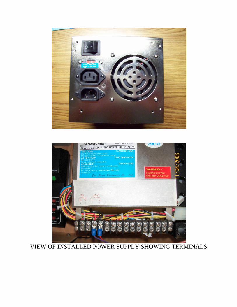
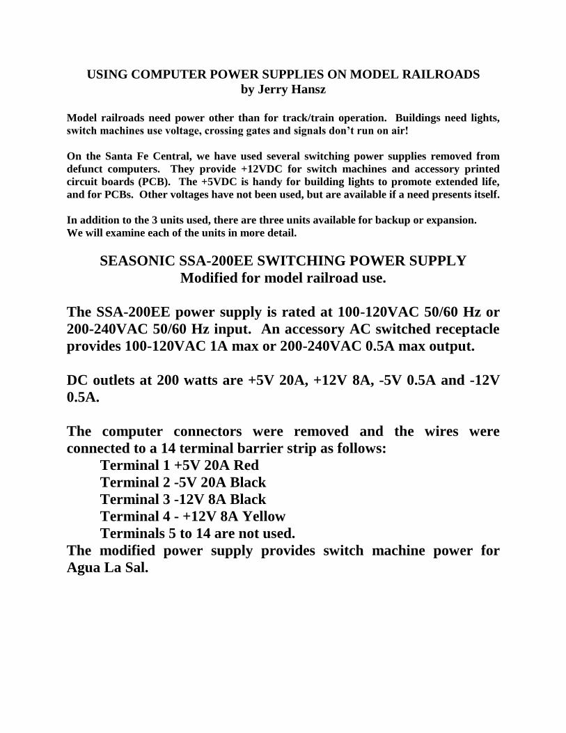
VIEW OF INSTALLED POWER SUPPLY SHOWING TERMINALS
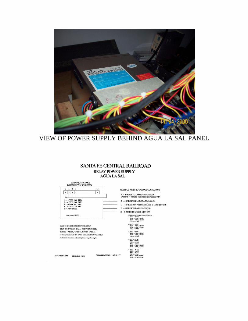
VIEW OF POWER SUPPLY BEHIND AGUA LA SAL PANEL
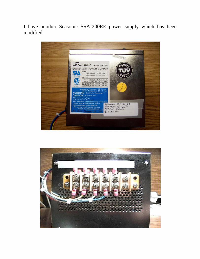
I have another Seasonic SSA-200EE power supply which has been
modified.
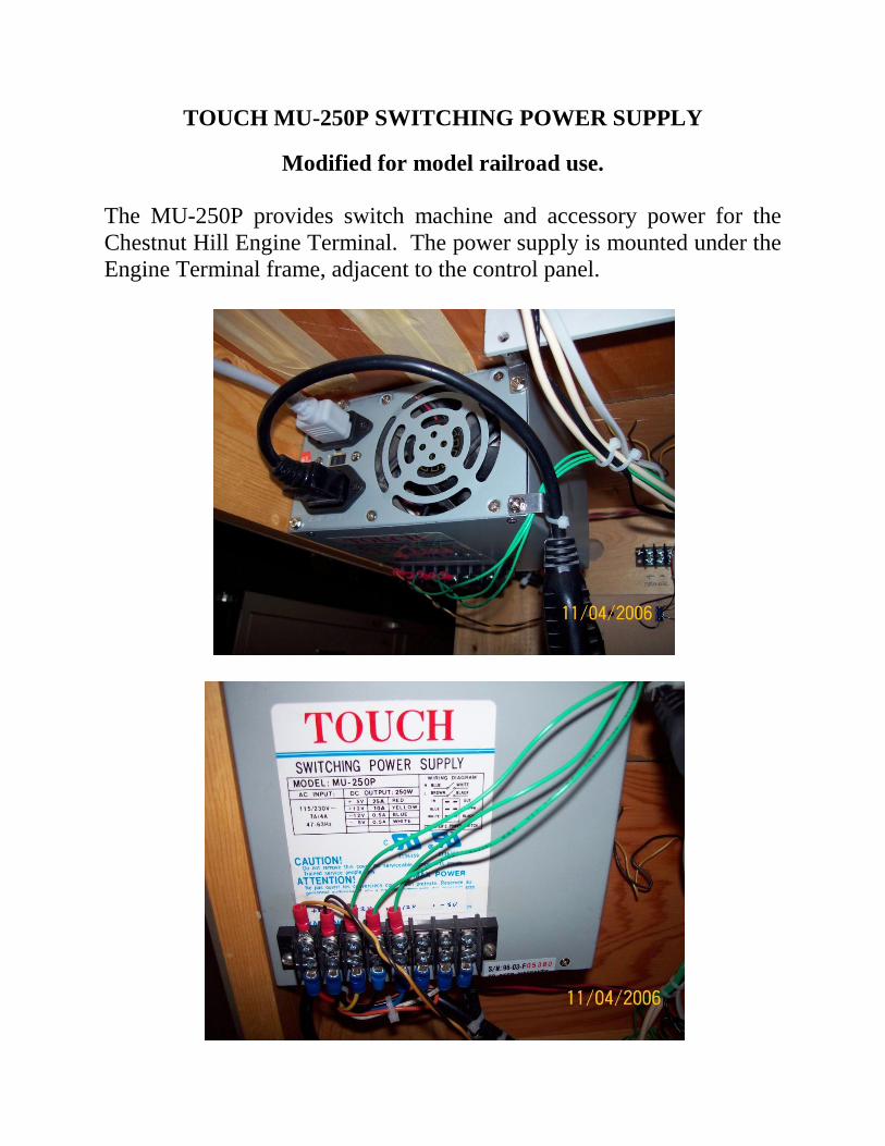
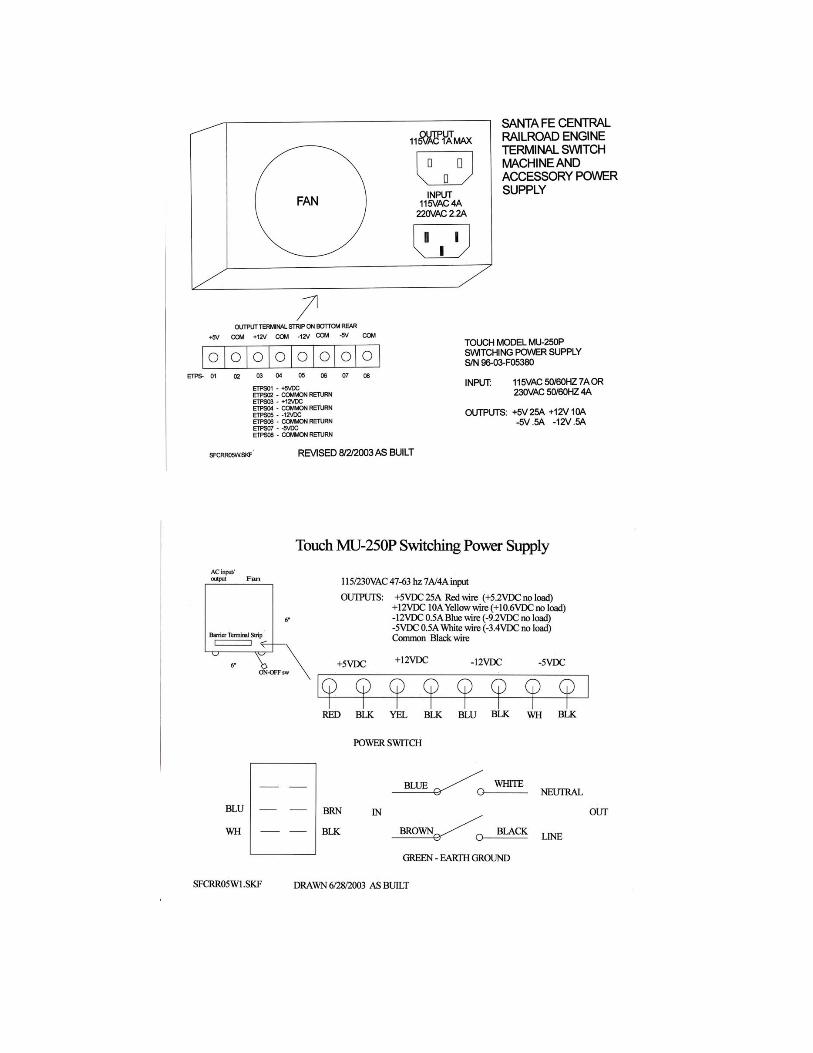
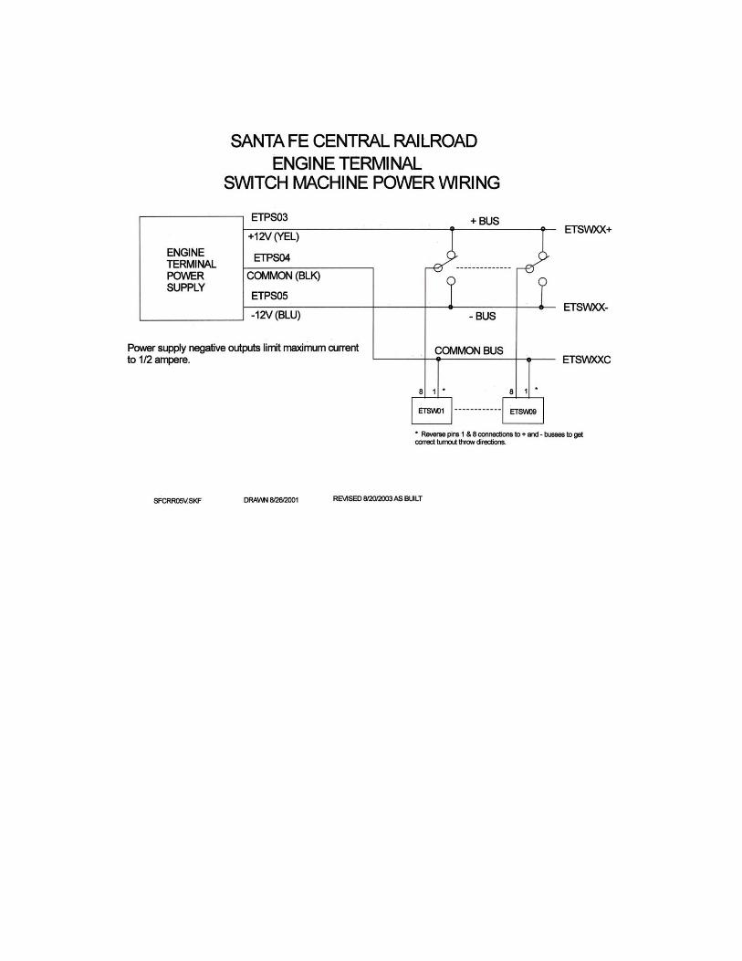
TOUCH MU-250P SWITCHING POWER SUPPLY
Modified for model railroad use.
The MU-250P provides switch machine and accessory power for the
Chestnut Hill Engine Terminal. The power supply is mounted under the
Engine Terminal frame, adjacent to the control panel.
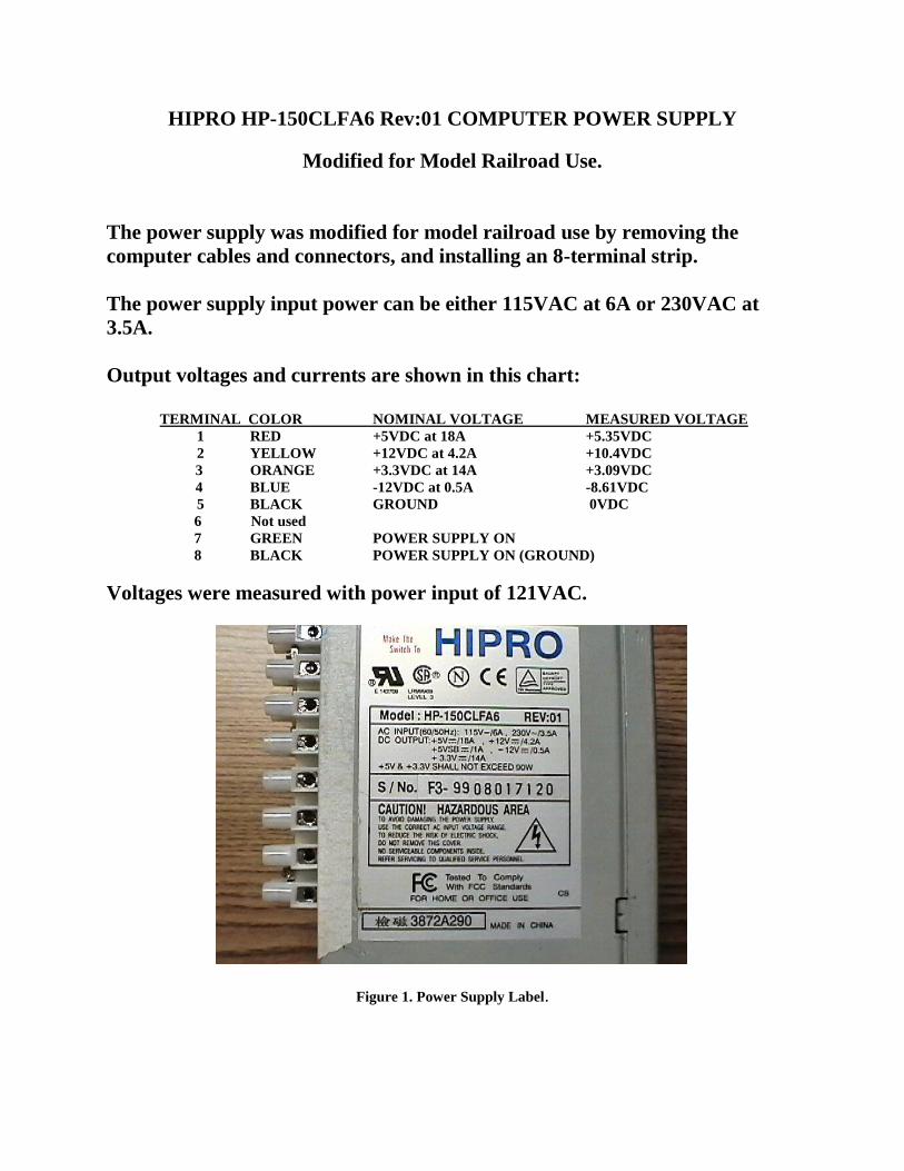
HIPRO HP-150CLFA6 Rev:01 COMPUTER POWER SUPPLY
Modified for Model Railroad Use.
The power supply was modified for model railroad use by removing the
computer cables and connectors, and installing an 8-terminal strip.
The power supply input power can be either 115VAC at 6A or 230VAC at
3.5A.
Output voltages and currents are shown in this chart:
TERMINAL COLOR NOMINAL VOLTAGE MEASURED VOLTAGE
1 RED +5VDC at 18A +5.35VDC
2 YELLOW +12VDC at 4.2A +10.4VDC
3 ORANGE +3.3VDC at 14A +3.09VDC
4 BLUE -12VDC at 0.5A -8.61VDC
5 BLACK GROUND 0VDC
6 Not used
7 GREEN POWER SUPPLY ON
8 BLACK POWER SUPPLY ON (GROUND)
Voltages were measured with power input of 121VAC.
Figure 1. Power Supply Label.

Figure 2. Fan and Terminal Strip. Figure 3. AC connector side.
To use the power supply, wires are connected to the required terminals, with
ground to terminal 5. A single-pole, single-throw (SPST) switch is connected
between terminals 7 and 8, to turn the power supply on.
Since connections to the power supply were not intuitive, we contacted the
Hipro support people at [email protected]. They kindly provided the
output voltages and their associated wire colors. Thanks to Diven Liu
([email protected]) for his assistance.
SPARKLE POWER INTERNATIONAL LTD. SPI-300G POWER SUPPLY
Modified for model railroad use
The SPI-300G computer power supply was modified for model railroad use by removing
redundant wiring, installing an 8-terminal strip, and modifying the switch wiring for a
SPST toggle switch.
When I get around to it, this power supply will be installed behind the Main Line Control
Panel at Talheim, to replace several power supplies cobbled together when the panel was
installed.
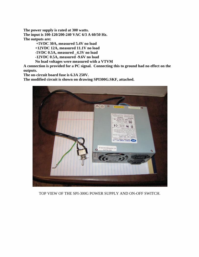
The power supply is rated at 300 watts.
The input is 100-120/200-240 VAC 6/3 A 60/50 Hz.
The outputs are:
+5VDC 30A, measured 5.4V no load
+12VDC 12A, measured 11.1V no load
-5VDC 0.5A, measured _4.3V no load
-12VDC 0.5A, measured -9.6V no load
No load voltages were measured with a VTVM
A connection is provided for a PC signal. Connecting this to ground had no effect on the
outputs.
The on-circuit board fuse is 6.3A 250V.
The modified circuit is shown on drawing SPI300G.SKF, attached.
TOP VIEW OF THE SPI-300G POWER SUPPLY AND ON-OFF SWITCH.
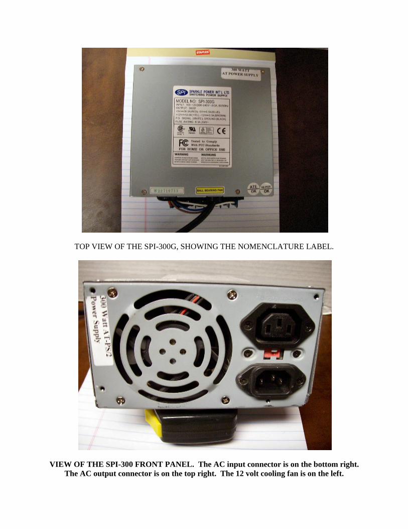
TOP VIEW OF THE SPI-300G, SHOWING THE NOMENCLATURE LABEL.
VIEW OF THE SPI-300 FRONT PANEL. The AC input connector is on the bottom right.
The AC output connector is on the top right. The 12 volt cooling fan is on the left.
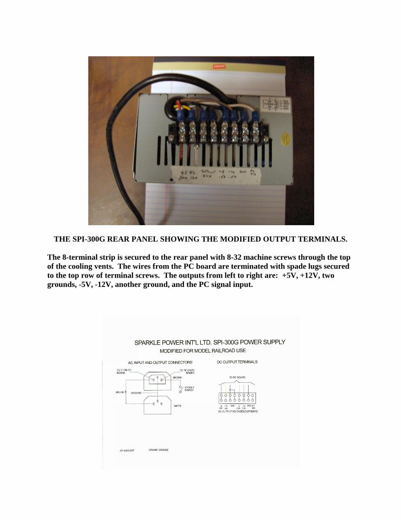
THE SPI-300G REAR PANEL SHOWING THE MODIFIED OUTPUT TERMINALS.
The 8-terminal strip is secured to the rear panel with 8-32 machine screws through the top
of the cooling vents. The wires from the PC board are terminated with spade lugs secured
to the top row of terminal screws. The outputs from left to right are: +5V, +12V, two
grounds, -5V, -12V, another ground, and the PC signal input.
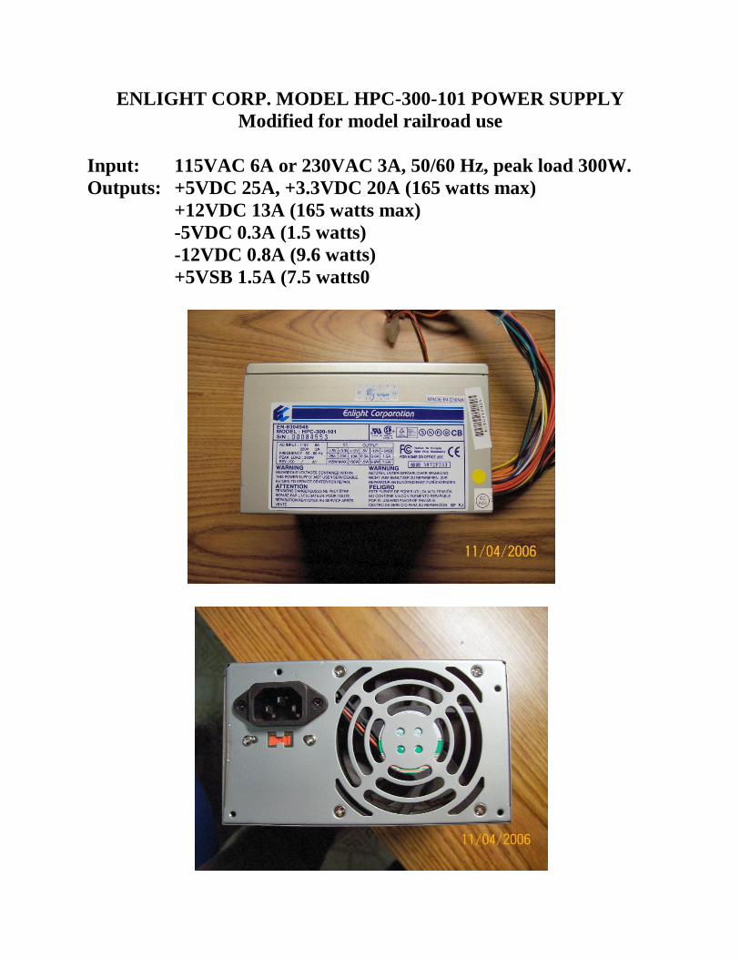
ENLIGHT CORP. MODEL HPC-300-101 POWER SUPPLY
Modified for model railroad use
Input: 115VAC 6A or 230VAC 3A, 50/60 Hz, peak load 300W.
Outputs: +5VDC 25A, +3.3VDC 20A (165 watts max)
+12VDC 13A (165 watts max)
-5VDC 0.3A (1.5 watts)
-12VDC 0.8A (9.6 watts)
+5VSB 1.5A (7.5 watts0
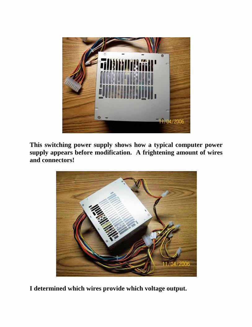
This switching power supply shows how a typical computer power
supply appears before modification. A frightening amount of wires
and connectors!
I determined which wires provide which voltage output.
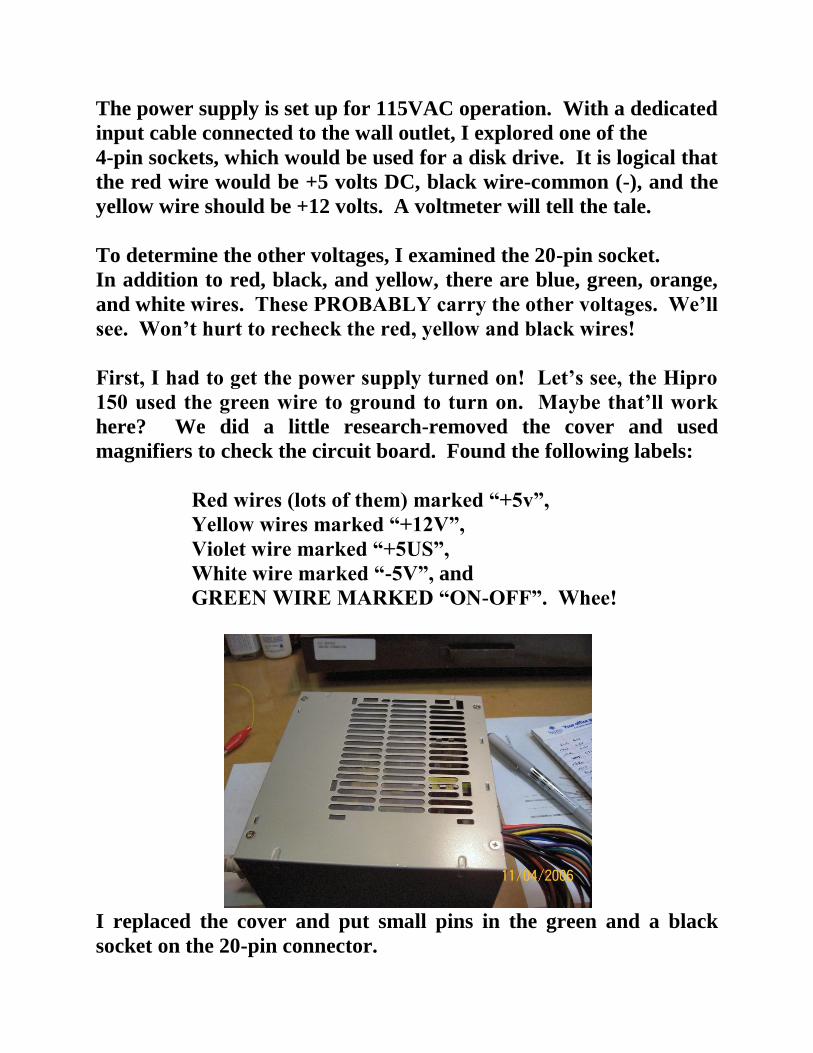
The power supply is set up for 115VAC operation. With a dedicated
input cable connected to the wall outlet, I explored one of the
4-pin sockets, which would be used for a disk drive. It is logical that
the red wire would be +5 volts DC, black wire-common (-), and the
yellow wire should be +12 volts. A voltmeter will tell the tale.
To determine the other voltages, I examined the 20-pin socket.
In addition to red, black, and yellow, there are blue, green, orange,
and white wires. These PROBABLY carry the other voltages. We’ll
see. Won’t hurt to recheck the red, yellow and black wires!
First, I had to get the power supply turned on! Let’s see, the Hipro
150 used the green wire to ground to turn on. Maybe that’ll work
here? We did a little research-removed the cover and used
magnifiers to check the circuit board. Found the following labels:
Red wires (lots of them) marked “+5v”,
Yellow wires marked “+12V”,
Violet wire marked “+5US”,
White wire marked “-5V”, and
GREEN WIRE MARKED “ON-OFF”. Whee!
I replaced the cover and put small pins in the green and a black
socket on the 20-pin connector.
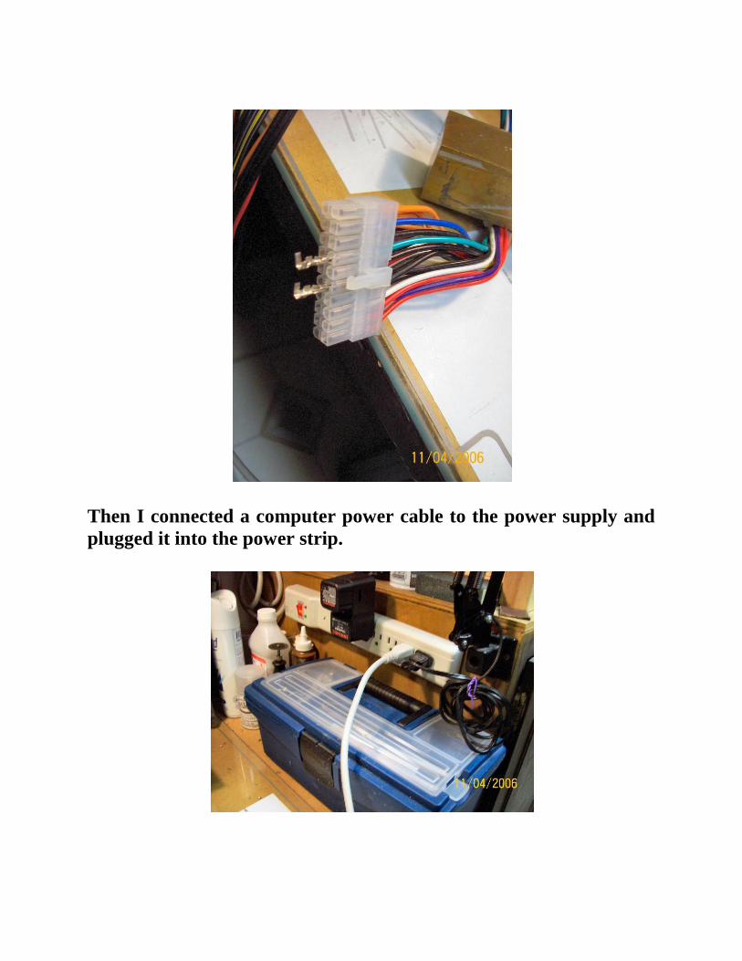
Then I connected a computer power cable to the power supply and
plugged it into the power strip.
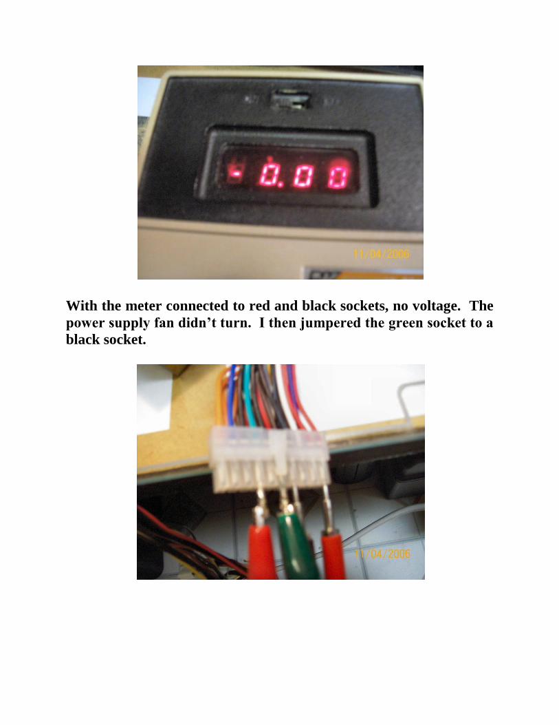
With the meter connected to red and black sockets, no voltage. The
power supply fan didn’t turn. I then jumpered the green socket to a
black socket.
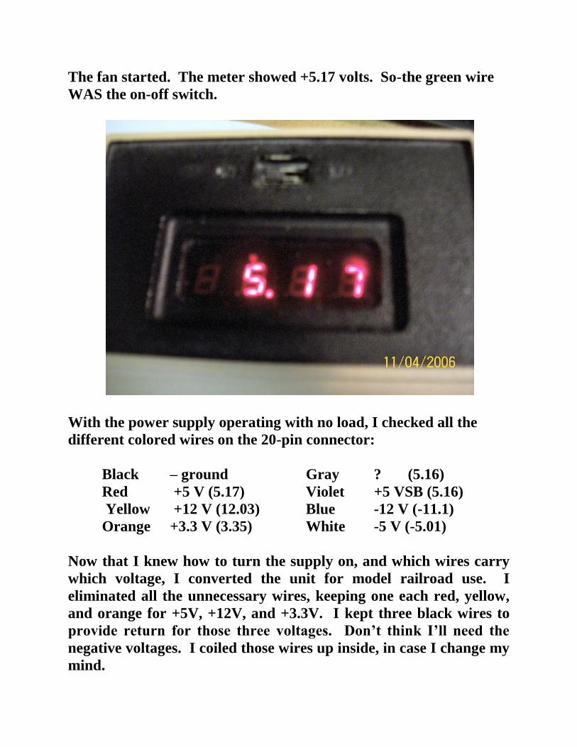
The fan started. The meter showed +5.17 volts. So-the green wire
WAS the on-off switch.
With the power supply operating with no load, I checked all the
different colored wires on the 20-pin connector:
Black – ground Gray ? (5.16)
Red +5 V (5.17) Violet +5 VSB (5.16)
Yellow +12 V (12.03) Blue -12 V (-11.1)
Orange +3.3 V (3.35) White -5 V (-5.01)
Now that I knew how to turn the supply on, and which wires carry
which voltage, I converted the unit for model railroad use. I
eliminated all the unnecessary wires, keeping one each red, yellow,
and orange for +5V, +12V, and +3.3V. I kept three black wires to
provide return for those three voltages. Don’t think I’ll need the
negative voltages. I coiled those wires up inside, in case I change my
mind.
The green wire and another black wire will go to a toggle switch, so
I can turn the power supply on. All cutting took place inside the
power supply so no bare wires will protrude.
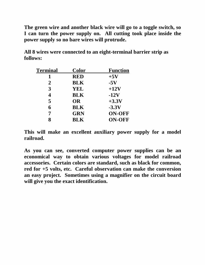
All 8 wires were connected to an eight-terminal barrier strip as
follows:
Terminal Color Function
1 RED +5V
2 BLK -5V
3 YEL +12V
4 BLK -12V
5 OR +3.3V
6 BLK -3.3V
7 GRN ON-OFF
8 BLK ON-OFF
This will make an excellent auxiliary power supply for a model
railroad.
As you can see, converted computer power supplies can be an
economical way to obtain various voltages for model railroad
accessories. Certain colors are standard, such as black for common,
red for +5 volts, etc. Careful observation can make the conversion
an easy project. Sometimes using a magnifier on the circuit board
will give you the exact identification.