Using Breakdown Phenomenon As Mobile Magnetic Field...
6
Abstract— Sensing magnetization and enhancing dynamics performances is essential while studying wireless magnetic mobile robots. Sensing physical parameters in microfluidic environments has strongly been demanded in various lab-on-a-chip applications as well. In this paper, we propose mobile microrobots as mobile sensor in microfluidics. We develop an original environment for high- resolution dynamic tracking and analysis in microfluidic chips. Studying robot dynamics in low Reynolds fluid with no magnetic sensor in the chip is challenging as the field distribution and robot magnetization are not well known. Our intended goal is to explore intrinsic magneto-fluidic sensing capacities to collect more information on the micro- system. We successfully integrate our robot into a transparent microfluidic chip for high-temporal resolution analysis of dynamics. We develop an electromagnetic setup allowing complete remote control (at low power ) of rotational behaviour. We study a breakdown phenomenon up to 1kHz signal and develop a scalar method analyzing rotational dynamics to enhance their sensing capacity. I. INTRODUCTION Using MEMS untethered micro-robots in fluids (microswimmers) as wireless manipulation tools has been developed widely with the intended goal to obtain in-vivo applications for biomedical [1-2], micromanipulation and/or cargo transport [3]. At micro/nanoscale, physics turns out to be quite different from macro-world and movements and/or regular operations remain quite challenging [4], low Reynolds number (with being density of fluid, its speed, a characteristic linear dimension and the dynamic viscosity) being much lower. Among other consequences - linearity, symmetry – as described in (1) by Stokes flow equation, a simplified version of Navier-Stokes: (1) (where is the viscosity of the fluid, its pressure, its velocity & f is an applied body force), the system is overdamped [5]. Inertial effects and other body forces are then predominated by surface phenomenona, such as viscous drag, electrostatic forces or capillarity. To perform swimming, several approaches are possible and have been explored. E. Coli Bacterium [5-7] because of its size and helical flagella, has the advantage of naturally fitting in-vivo environments but controlling their movement relies on complex processes such as chemotaxis [6] or biophysics phenomena [7], with a very limited control of movement for external users. Some other works have focused on developing hybrid swimmers [8-9], combining metallic materials with living organisms. Thanks to the advances in microfabrications Figure 1. Top: capture of an example design of MagPole, schematic of actuating principle in damped environment & sensing at cut-off frequency; Below: Magnetization M tend to align to magnetic field B in any direction of the plan and dynamic remote control with robotics, MEMS offer now a broad spectrum of development for purely artificial solutions [10], with a precise control over geometry, material and propulsion. Different particles have been designed, from nanobeads [3] to millimetric bodies [10]. Remote interaction has been achieved in dry and wet environment [11] using electrophoresis [12-13]or piezoelectric effects [14] but they require electrodes around the swimmer. Magnetic waves [15-19] have the advantage of generating a force and a torque over ferromagnetic corpses thanks to their magnetization without disturbing electrochemical equilibrium. To obtain higher D.O.F and faster time-response, using electromagnets controlled by digital-analog conversion should be considered rather than permanent magnets. As it is difficult to know the field distribution of a magnetic device in microfluidics – due to confinement, oxidation and fabrication limitation, developing sensing capacities directly from the microswimmer is a major issue, needing to better understand dynamics i.e. magnetic forces at stake. We will see in section II it means determining local amplitude as well as field gradient. Finally, if knowing more about “what” is swimming and “how” is still of great interest, “where” has not been much explored. Environments such as microfluidic chip (lab-on- chip) [20] offer an adapted framework to study in-vitro applications and our goal here is to develop mobile Using Breakdown Phenomenon As Mobile Magnetic Field Sensor in Microfluidics Hugo Salmon, Student Member, IEEE, Laurent Couraud and Gilgueng Hwang, Member, IEEE 2013 IEEE/RSJ International Conference on Intelligent Robots and Systems (IROS) November 3-7, 2013. Tokyo, Japan 978-1-4673-6357-0/13/$31.00 ©2013 European Union 2041
Transcript of Using Breakdown Phenomenon As Mobile Magnetic Field...

Abstract— Sensing magnetization and enhancing
dynamics performances is essential while studying wireless
magnetic mobile robots. Sensing physical parameters in
microfluidic environments has strongly been demanded in
various lab-on-a-chip applications as well. In this paper, we
propose mobile microrobots as mobile sensor in
microfluidics. We develop an original environment for high-
resolution dynamic tracking and analysis in microfluidic
chips. Studying robot dynamics in low Reynolds fluid with
no magnetic sensor in the chip is challenging as the field
distribution and robot magnetization are not well known.
Our intended goal is to explore intrinsic magneto-fluidic
sensing capacities to collect more information on the micro-
system. We successfully integrate our robot into a
transparent microfluidic chip for high-temporal resolution
analysis of dynamics. We develop an electromagnetic setup
allowing complete remote control (at low power ) of
rotational behaviour. We study a breakdown phenomenon
up to 1kHz signal and develop a scalar method analyzing
rotational dynamics to enhance their sensing capacity.
I. INTRODUCTION
Using MEMS untethered micro-robots in fluids (microswimmers) as wireless manipulation tools has been developed widely with the intended goal to obtain in-vivo applications for biomedical [1-2], micromanipulation and/or cargo transport [3]. At micro/nanoscale, physics turns out to be quite different from macro-world and movements and/or regular operations remain quite
challenging [4], low Reynolds number (with
being density of fluid, its speed, a characteristic linear dimension and the dynamic viscosity) being much lower. Among other consequences - linearity, symmetry – as described in (1) by Stokes flow equation, a simplified version of Navier-Stokes:
(1)
(where is the viscosity of the fluid, its pressure, its velocity & f is an applied body force), the system is overdamped [5]. Inertial effects and other body forces are then predominated by surface phenomenona, such as viscous drag, electrostatic forces or capillarity.
To perform swimming, several approaches are possible and have been explored. E. Coli Bacterium [5-7] because of its size and helical flagella, has the advantage of naturally fitting in-vivo environments but controlling their movement relies on complex processes such as chemotaxis [6] or biophysics phenomena [7], with a very limited control of movement for external users.
Some other works have focused on developing hybrid swimmers [8-9], combining metallic materials with living organisms. Thanks to the advances in microfabrications
Figure 1. Top: capture of an example design of MagPole, schematic of actuating principle in damped environment & sensing at cut-off
frequency; Below: Magnetization M tend to align to magnetic field B in
any direction of the plan
and dynamic remote control with robotics, MEMS offer now a broad spectrum of development for purely artificial solutions [10], with a precise control over geometry, material and propulsion. Different particles have been designed, from nanobeads [3] to millimetric bodies [10]. Remote interaction has been achieved in dry and wet environment [11] using electrophoresis [12-13]or piezoelectric effects [14] but they require electrodes around the swimmer. Magnetic waves [15-19] have the advantage of generating a force and a torque over ferromagnetic corpses thanks to their magnetization without disturbing electrochemical equilibrium. To obtain higher D.O.F and faster time-response, using electromagnets controlled by digital-analog conversion should be considered rather than permanent magnets.
As it is difficult to know the field distribution of a magnetic device in microfluidics – due to confinement, oxidation and fabrication limitation, developing sensing capacities directly from the microswimmer is a major issue, needing to better understand dynamics i.e. magnetic forces at stake. We will see in section II it means determining local amplitude as well as field gradient. Finally, if knowing more about “what” is swimming and “how” is still of great interest, “where” has not been much explored. Environments such as microfluidic chip (lab-on-chip) [20] offer an adapted framework to study in-vitro applications and our goal here is to develop mobile
Using Breakdown Phenomenon As Mobile Magnetic Field Sensor in
Microfluidics
Hugo Salmon, Student Member, IEEE, Laurent Couraud and Gilgueng Hwang, Member, IEEE
2013 IEEE/RSJ International Conference onIntelligent Robots and Systems (IROS)November 3-7, 2013. Tokyo, Japan
978-1-4673-6357-0/13/$31.00 ©2013 EuropeanUnion
2041
magnetic field sensor adapted to such microfluidic devices. We propose and extend our recently developed ferromagnetic micromobile robots named MagPol [21] for its capacity to POLarize MAGnetically– see Fig.1 pictures. It can enlarge the area of exploration in-vitro combining lab-on-chip and micro-robotics. It could open the way for in-vitro operations with broad applications for manipulation but also sensing, especially in harsh and inaccessible environment like liquid with toxicity or wide thermodynamic conditions. We have recently demonstrated full-planar motion and ability to polarize and manipulate micro-objects in microfluidics with an original strategy. We here focus exclusively on its dynamics to demonstrate its ability as a magnetic transducer (sensor and actuator). Though low Reynolds number induce a heavily damped environment, it can also become with simpler physics as a measuring tool for its environment, using an optical or magnetic torque momentum [22]. The magnetic field sensing is based on monitoring the cut-off frequency and the speed of the microrobot while their rotation and translational motion by external rotating magnetic field. The advantage of using MagPol is demonstrating high dynamics and control in both rotational and translational motions in such confined microfluidic environments, enhancing the magnetic field sensing temporal resolution.
In this paper, we integrate our microrobot in an original PDMS (polydiméthylsiloxane)/Glass microfluidic chip and develop a specific chain of command for sensing capacities. After reminding in section 2 the principles of Adler theory [23] on the breakdown phenomenon studied, the system overview and its important role in transducing will be described in the section 3. We then compare in section 4 experimental results to model and demonstrate first qualitative and quantitative results on magnetization sensing. In the final section, we discuss the perspective of development of those sensing capacities and applications.
II. WIRELESS IMMERSED TRANSDUCING
Any torque τ applied on the vertical axis z of a particle
in Stokes fluid, because of heavy damping, is directly
related to the particle angular speed (we neglect the
inertial term) in the differential equation (2)
(2)
where is the striction coefficient toward, is the
angular position & the derivative with respect to time.
If we generate a uniform magnetic field on a particle
containing ferromagnetic material magnetized
horizontally,
( ) (3)
(4)
M being the magnetization of the ferromagnetic parts,
the direction of the uniform field, it induces exclusively a
torque – equation (4) - toward vertical axis, because of
field uniformity and horizontal magnetization. The
consequence is two position of equilibrium on the
symmetry axis, one only being stable and the particle
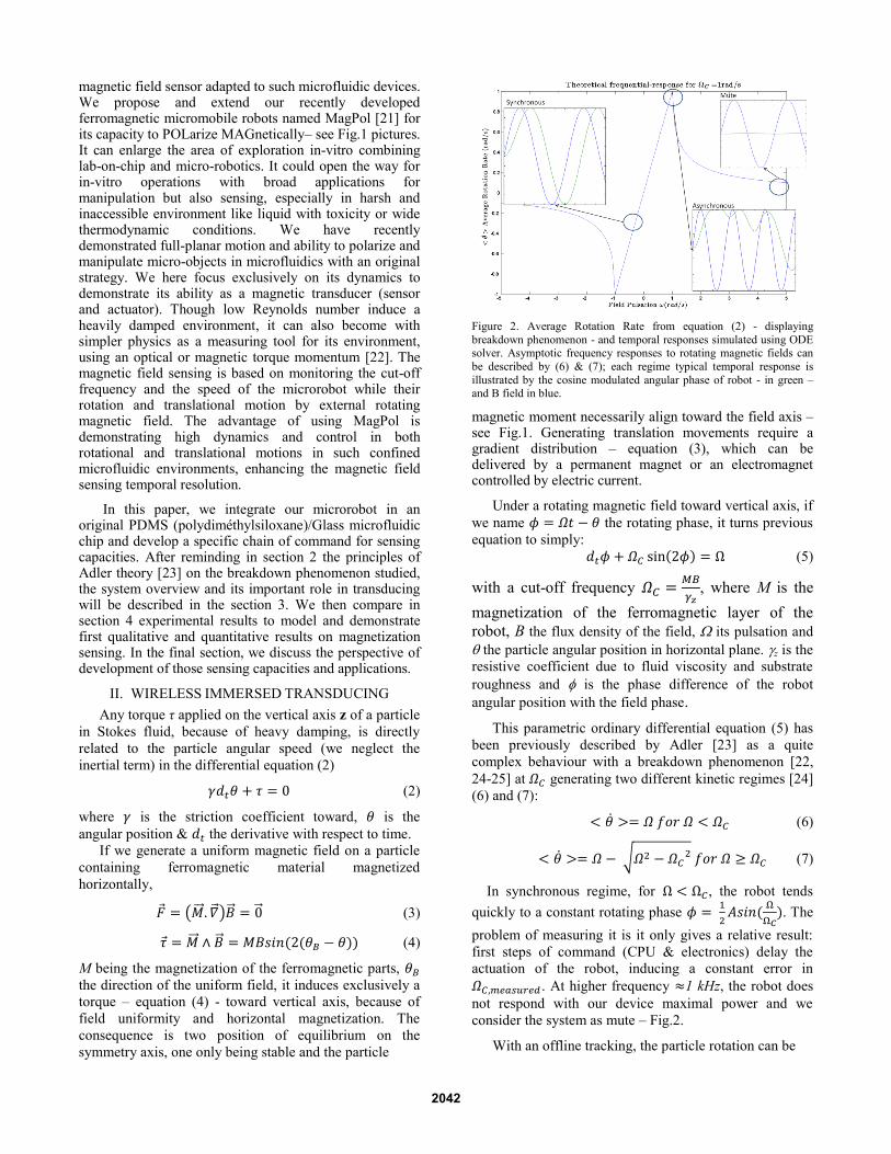
Figure 2. Average Rotation Rate from equation (2) - displaying
breakdown phenomenon - and temporal responses simulated using ODE solver. Asymptotic frequency responses to rotating magnetic fields can
be described by (6) & (7); each regime typical temporal response is
illustrated by the cosine modulated angular phase of robot - in green – and B field in blue.
magnetic moment necessarily align toward the field axis – see Fig.1. Generating translation movements require a
gradient distribution – equation (3), which can be delivered by a permanent magnet or an electromagnet controlled by electric current.
Under a rotating magnetic field toward vertical axis, if
we name the rotating phase, it turns previous
equation to simply:
(5)
with a cut-off frequency
, where M is the
magnetization of the ferromagnetic layer of the
robot, B the flux density of the field, its pulsation and
the particle angular position in horizontal plane. z is the
resistive coefficient due to fluid viscosity and substrate
roughness and is the phase difference of the robot
angular position with the field phase.
This parametric ordinary differential equation (5) has
been previously described by Adler [23] as a quite
complex behaviour with a breakdown phenomenon [22,
24-25] at generating two different kinetic regimes [24]
(6) and (7):
(6)
√ (7)
In synchronous regime, for , the robot tends
quickly to a constant rotating phase
. The
problem of measuring it is it only gives a relative result:
first steps of command (CPU & electronics) delay the
actuation of the robot, inducing a constant error in
. At higher frequency 1 kHz, the robot does
not respond with our device maximal power and we
consider the system as mute – Fig.2.
With an offline tracking, the particle rotation can be
2042
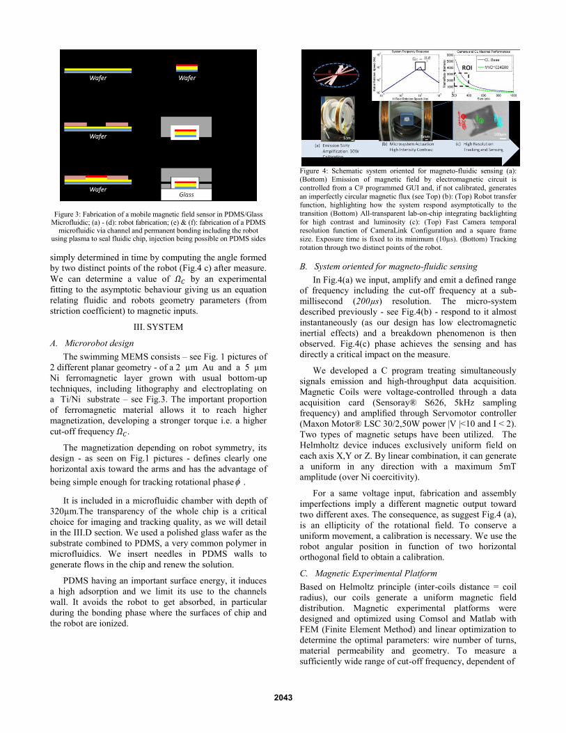
Figure 3: Fabrication of a mobile magnetic field sensor in PDMS/Glass Microfluidic; (a) - (d): robot fabrication; (e) & (f): fabrication of a PDMS
microfluidic via channel and permanent bonding including the robot using plasma to seal fluidic chip, injection being possible on PDMS sides
simply determined in time by computing the angle formed
by two distinct points of the robot (Fig.4 c) after measure.
We can determine a value of by an experimental
fitting to the asymptotic behaviour giving us an equation
relating fluidic and robots geometry parameters (from
striction coefficient) to magnetic inputs.
III. SYSTEM
A. Microrobot design
The swimming MEMS consists – see Fig. 1 pictures of
2 different planar geometry - of a 2 µm Au and a 5 µm
Ni ferromagnetic layer grown with usual bottom-up
techniques, including lithography and electroplating on
a Ti/Ni substrate – see Fig.3. The important proportion
of ferromagnetic material allows it to reach higher
magnetization, developing a stronger torque i.e. a higher
cut-off frequency .
The magnetization depending on robot symmetry, its
design - as seen on Fig.1 pictures - defines clearly one
horizontal axis toward the arms and has the advantage of
being simple enough for tracking rotational phase .
It is included in a microfluidic chamber with depth of
320µm.The transparency of the whole chip is a critical
choice for imaging and tracking quality, as we will detail
in the III.D section. We used a polished glass wafer as the
substrate combined to PDMS, a very common polymer in
microfluidics. We insert needles in PDMS walls to
generate flows in the chip and renew the solution.
PDMS having an important surface energy, it induces
a high adsorption and we limit its use to the channels
wall. It avoids the robot to get absorbed, in particular
during the bonding phase where the surfaces of chip and
the robot are ionized.
Figure 4: Schematic system oriented for magneto-fluidic sensing (a): (Bottom) Emission of magnetic field by electromagnetic circuit is
controlled from a C# programmed GUI and, if not calibrated, generates
an imperfectly circular magnetic flux (see Top) (b): (Top) Robot transfer function, highlighting how the system respond asymptotically to the
transition (Bottom) All-transparent lab-on-chip integrating backlighting
for high contrast and luminosity (c): (Top) Fast Camera temporal resolution function of CameraLink Configuration and a square frame
size. Exposure time is fixed to its minimum (10µs). (Bottom) Tracking
rotation through two distinct points of the robot.
B. System oriented for magneto-fluidic sensing
In Fig.4(a) we input, amplify and emit a defined range
of frequency including the cut-off frequency at a sub-
millisecond (200µs) resolution. The micro-system
described previously - see Fig.4(b) - respond to it almost
instantaneously (as our design has low electromagnetic
inertial effects) and a breakdown phenomenon is then
observed. Fig.4(c) phase achieves the sensing and has
directly a critical impact on the measure.
We developed a C program treating simultaneously
signals emission and high-throughput data acquisition.
Magnetic Coils were voltage-controlled through a data
acquisition card (Sensoray® S626, 5kHz sampling
frequency) and amplified through Servomotor controller
(Maxon Motor® LSC 30/2,50W power |V |<10 and I < 2).
Two types of magnetic setups have been utilized. The
Helmholtz device induces exclusively uniform field on
each axis X,Y or Z. By linear combination, it can generate
a uniform in any direction with a maximum 5mT
amplitude (over Ni coercitivity).
For a same voltage input, fabrication and assembly
imperfections imply a different magnetic output toward
two different axes. The consequence, as suggest Fig.4 (a),
is an ellipticity of the rotational field. To conserve a
uniform movement, a calibration is necessary. We use the
robot angular position in function of two horizontal
orthogonal field to obtain a calibration.
C. Magnetic Experimental Platform
Based on Helmoltz principle (inter-coils distance = coil
radius), our coils generate a uniform magnetic field
distribution. Magnetic experimental platforms were
designed and optimized using Comsol and Matlab with
FEM (Finite Element Method) and linear optimization to
determine the optimal parameters: wire number of turns,
material permeability and geometry. To measure a
sufficiently wide range of cut-off frequency, dependent of
2043

Figure 5: Comparison of simulated solutions (Runge-Kutta method) in
continuous line and experimental (with tracking) frequency- response
marked point for three different rotating magnetic fields
magnetic flux density amplitude, we need to transfer as
much magnetic power as possible minimizing source-
robot distance and maximizing coils’ current volume.
Polymer supports were fabricated with a three-
dimensional additive manufacturer.To confirm the
previous hypothesis of purely rotational movement, one
other challenge is to contain the chip in a domain where
the field is actually uniform (with less than a 5% global
variation). We determined it comparing our simulation to
a measure with a Hall effect sensor and made our chips fit
it in the defined region.
D. Optics
As magnetic devices are too big or lenses working
distance is too small to be included in standard
microscope, we used a Navitar® zoom lens on top of the
setup adapted for our study requirements. Attached on a
manually controllable 6 DOF optical arm, it is possible to
position anywhere without being in contact with any of
the coils or sample.
Lighting is achieved either directly from the Navitar®
lens with an included semi-reflecting mirror or from the
bottom by an optical fiber source. If top-lighting can be an
advantage because directly done from the lens, we
observe a much better contrast and intensity in the second
configuration. Moreover, as the light is transmitted and
not reflected from the robot, it avoids instability of the
robot texture during tracking. As fast frame-rate (>5
kframe/s) and tracking require respectively high intensity
(exposure<ms) and steady high contrast, backlighting is
highly recommended for a fine measurement.
E. Fast Imaging & Tracking
We used a Photonfocus® fast frame-rate camera
directly connected via Camera Link protocol (allowing a
maximum rate of 255 GBytes/s in BASE configuration).
CL protocol is one of the fastest way to obtain directly to
the computer such a high framerate and CMOS Camera
usually work with it. Obtaining higher framerate is
possible only using embarked cameras with their own
RAM and cooling system. It is not necessary for the
dynamics we observe and it is a completely different
budget. As we can see on Fig.4 (c) graph, camera
performances (in green) in term of frame rate are
necessary lower than Camera Link limitations. The frame
rate tframe, mainly depending of the exposure time and
readout time, is the inverse of the frame time. The
minimum frame time is calculated in sequential mode at
constant framerate by:
(8)
where times on the right side of (8) are respectively
exposure, readout, processing and RAM (Random Access
Memory).As we can neglect processing and RAM
refreshing time, depending of the computer performances
-supposedly sufficient, it depends on exposure (>10µs)
and readout time - directly related to the frame size.
Acquisition are stocked on a direct memory allocation
then converted in video and post treated using Tracker®
open-source code. Two-points tracking allows extracting
the angular phase from the visual data and identifying the
breakdown phenomenon with a precision of the size of a
pixel (~ 1-10 microns).
IV. SENSING DEMONSTRATION
To quickly demonstrate sensing capacity, we
experiment with low temporal resolution (60Hz step) the
variations of Magnetic flux and deduce a first qualitative
result on the Magnetization of microrobot MagPol.
A. Uniform field sensing experimental demonstration
Protocol: we used the same chip/robot couple for all
this study and realized it in isopropanol (IPA) at same
concentration. We positioned it at the centre of the chip
and magnetized it to saturation by putting in contact to the
chip to a 1T permanent magnet (> Ni saturation
magnetization). We generated the planar circular rotating
field with a frequency varying from 1 to 400Hz with a
60Hz step. We input three different voltages, inducing a
up-to 5mT magnetic flux. We can analyze dynamics with
up-to 10 images per revolution at maximal frequency. We
then integrate the signal to obtain an average rotation. We
repeated the study for three different power input
(calibrated i.e. no ellipticity). The post-treatment of
recorded sequences is done using a tracking detecting
robot shape and measuring angular variation between
each frame.
Observation: The frequency-responses simulated on
Matlab fits the experiment in the microfluidic chip on
Fig.5, with what seems already to be a proportional
dependency between magnetic power and cut-off
frequency. If we define sensibility of the system as the
variation of depending on the power, we obtain an
experimental value of 8.081 rad/(s.mT).
We observe in Fig. 6 the experiment fit the response to
2044

Figure 6. Cut-off frequency in function of a rotating magnetic field
amplitude, with linear fitting using least-square methodseveral
powers a linear response giving us the ratio between
magnetization and viscosity ratio and confirming the
material was magnetized. As we treated exclusively the
magnetized case which is linear, few points are necessary
to determine the coefficient of the line.Nickel being a soft
ferromagnetic material of known initial susceptibility
=109 (unitless), coercitivity Hc=2mT and
saturation =0.48 106A/m [26], we expect the
two extreme cases:
{
where is vacuum permeability ( the fluid
viscosity). First qualitative result is the confirmation from
Fig. 6 that the robot remains magnetized, the cut-off
frequency being directly proportional to the magnetic flux
. A non-magnetized or demagnetized
(possible, due to low coercitivity) robot would have had a
quadratic variation with the information that allows, as the
Ni saturation value is typically 0.48A/m at ambient
temperature, to approximate the value of the damping
coefficient.
B. Gradient field dynamics
Protocole: We induced a gradient distribution using
a dome containing 4 electromagnets on orthogonal
axes and sharing a common center. Being able to
generate a force in any direction of the plane by linear
superposition of the axes gradients, we can achieve a
movement with up-to 30mT amplitude of field and
3mT/cm gradient, position it anywhere and analyze its
dynamics at high framerate using a tracking algorithm. A
0.8V step input on an arbitrary axis generates a gradient
magnetic field constant in time. We can then compare to
the dynamics predicted by our approximation.
TABLE I. EXPERIMENTS PARAMETERS, FORCE INVOLVED AND RE
mRobot
ng
cP
kg.s/m
amax
m/s2 Vmax
m/s Fdrag
nN m.ax
pN Re
3.56 1.96 250 9.24e-6 58.5 0.07 648 21 10-2
Figure 7. (a) Translational motion dynamics by gradient magnetic
field induced with a 0.8 V input on a single axis . High temporal
resolution (here 6600 frame/s) allows by tracking the robot position (b)
to reach the speed values (c) and obtain a range of the force applied on
the microrobot through acceleration (d). 3mm translation in 90ms with a constant in time input in backward motion. 1pixel~11.7µm
Observation: Microrobot, with a high proportion of
ferromagnetic part, can reach high-speed –
Fig.7(b). At maximum speed, we reach the limit
(10-2
) of low Reynolds fluid. Striction makes it
difficult to control at low-speed too. It requires a
high-temporal resolution as well as a sufficient
resolution of field amplitude, i.e. voltage input. We
obtain with a sub-millisecond resolution the translational
motion dynamics - Fig. 7 - on axis in the position y.
Supposing at low power we are still in Low Reynolds
approximation as in Section II, magnetic torque is
directly related to the viscosity & microrobot speed
(7)
where is the Stokes drag coefficient,
acceleration, acceleration, IPA viscosity at 25°C and
Stokes radius (radius of a sphere containing the robot).
We used Fig.7 data to complete Table I. We deduced the
Forces at stake and Re, justifying we can neglect inertia
term for Eq. (7). Varying the power input and y position,
we can determine a complementary scalar relation
between magnetic gradient distribution and
hydrodynamics.
V. CONCLUSION
A. Sensing Applications
Our system has demonstrated ability to determine the
magnetization of the robot - see performances in Table II.
TABLE II. MAGNETO-FLUIDIC SENSING APPLICATIONS OF
MEASURING C
B range Bandwidth Q Sensitivity Hz/mT
Spatial / Time
resolution
5mT 0-500Hz 1-1.4 8.081 500µm / 200µs
It can act as well - Table III - as a calibration tool for
magnetic rotating field or a sensor of local viscosity of the
fluid, the spatial resolution being the range of its in-plane
2045

dimensions. It also provides, see Table III, an interesting
tool for microswimmers development and microfluidics.
It provides a scalar criterion which, depending on
fixedparameters, determining experimentally an unknown
variable. We can determine best geometries and
environment for rotational motion and know more about
the fluidic environment. This is given by if
we suppose the drag coefficient directly proportional to
the volume V of the robot and the fluid viscosity ν, the
shape factor κ of the artificial swimmer.
TABLE III. MAGNETO-FLUIDIC SENSING APPLICATIONS OF
MEASURING C
Constants Variable Applications
M, B, ν and V κ Robot Optimization
M, B, κ and V ν Sensing Environment
B or M, κ, and V M or B
B. Future prospect
Transducing capacities (sensor as well as actuator) of
MagPol in microfluidic chip have been compared to
theory and confirmed. The system resolution is limited in
power by the earth magnetic field and electromagnetic
interferences, but a Faraday cage could increase it. Real-
time sensing of the angular position could be achieved
using an optimized tracking algorithm. It would simplify
the long data treatment required by offline tracking. We
could also extend the analysis by extracting more
information from the excitable state by perturbing the
input signals [25], obtaining more information about
borders position. To control the position of the robot,
adding complementary electromagnets - inducing
magnetic gradient i.e. force – see Eq. (3) - to the Helmoltz
setup controlling horizontal axes might be considered.
Moreover, we now understand more the simple case of a
uniform distribution but the more general case of gradient
field distribution generate a translation movement in the
direction of the magnetic dipole that is also damped,
which means the speed is directly proportional to the
power input. With an adapted tracking and model – see
Fig.7, we could enlarge this study.
ACKNOWLEDGMENT
We acknowledge LPN cleanroom staffs in particular
S. Guilet, L. Ferlazzo, and C. Roblin for microfabrication.
H. S. thanks S. Barbaye, C. Gosse for fruitful discussions.
REFERENCES:
[1] M. Hofmann-Amtenbrink, B. von Rechenberg and H. Hofmann,
”Superparamagnetic nanoparticles for biomedical applications” in
Nanostructured Materials for Biomedical Applications, 2009, pp 119-149.
[2] Jordan, R. Scholz, P. Wust, H. Fahling and R. Felix, ”Magnetic
fluid hyperthermia (MFH): Cancer treatment with AC magnetic field induced excitation of biocompatible superparamagnetic
nanoparticles” in Journal of Magnetism and Magnetic Materials,
201, 1999, pp 413-419. [3] C. Gosse and V. Croquette, ”Magnetic Tweezers:
Micromanipulation and Force Measurement at the Molecular
Level” in Biophysical Journal vol. 82 issue 6, June 2002.
[4] M. Purcell, ”Life at low Reynolds” (American Institute of Physics)
in. AIP Conf. Proc. 28, pp. 49-64, 1977. [5] Guyon, J.-P. Hulin and L. Petit, ”Hydrodynamique Physique” in
CNRS Edition, 2001.
[6] Y. Sowa1, A.D. Rowe, M.C. Leake, T. Yakushi, M. Homma, A. Ishijima and R. M. Berry, ”Direct observation of steps in rotation
of the bacterial flagellar motor” in Nature 437, 2005, pp. 916-919.
[7] H.C. Berg and D.A. Brown, ”Chemotaxis in Escherichia coli analysed by Three-dimensional Tracking” in Nature 239, 1972
[8] S. Chattopadhyay, R. Moldovan, C. Yeung and X. L. Wu,
”Swimming efficiency of bacterium Escherichia coli in Proceedings of the National Academy of Science of the United
States of America (PNAS), vol. 103, 2006, pp. 13712-13717.
[9] S. Martel, M. Mohammadi, O. Felfoul, Z. Lu and P. Pouponneau, ”Flagellated Magnetotactic Bacteria as Controlled MRItrackable
Propulsion and Steering Systems for Medical Nanorobots
Operating in the Human Microvasculature” in IJRR 28 no.4, 2009, pp.571-582.
[10] J.J. Abbott, K.E. Peyer, M. C. Lagomarsino, L. Zhang, L. Dong
and B. J. Nelson, ”How should Microrobots swim?” in IJRR 28 no.11-12, pp.1434-1447, Nov. 2009.
[11] T. Kawahara, F. Lin, Y. Yamanishi and F. Arai, ”High
performance magnetically driven microtools with ultrasonic vibration for biomedical innovations” in ICRA 2011, pp. 3453 -
3454.
[12] G. Hwang, S. Haliyo and S. Rgnier, ”Remotely Powered Propulsion of Helical Nanobelts” in Proceedings of Robotics:
Science and Systems VI, 2011 [13] S.T. Chang, V.N. Paunov, D.N. Petsev and O. D. Velev,
”Remotely powered self-propelling particles and micropumps
based on miniature diodes” in Nature Materials 6, 2007, pp. 235-240.
[14] I.A. Ivan, G. Hwang, J. Agnus, M. Rakotondrabe, N. Chaill and S.
Rgnier, ”An impulsive and space-dependant in-plane control of MagPieR: the magnetic and piezoelectric microrobot” in ICRA
2011, pp.102-108.
[15] D.R. Frutiger, K. Vollmers, B.E. Kratochvil, B.J. Nelson, ”Small, Fast, and Under Control: Wireless Resonant Magnetic Micro-
agents” in IJRR vol 29 no. 5, 2010, pp. 613-636.
[16] C. Pawashe, S. Floyd and M. Sitti, ”Multiple magnetic microrobot control using electrostatic anchoring” in Applied Physics Letters,
vol.94, 2009, pp. 164-108.
[17] W. Mahoney, J. C. Sarrazin, E. Bamberg and J. J. Abbott,”Velocity Control with Gravity Compensation for
Magnetic Helical Microswimmers” in Advanced Robotics 25
(2011) 10071028. [18] A.F. Tabak and S Yesilyurt ”Experiment-Based Kinematic
Validation of Numeric Modeling and Simulated Control of an
Untethered Biomimetic Microrobot in Channel” [19] P. Tierno, R. Golestanian, I. Pagonabarraga and F. Sagus,
”Controlled Swimming in Confined Fluids of Magnetically
Actuated Colloidal Rotors” in Phys. Rev. Lett. vol 101 no.21, 2008.
[20] Y. Gao, A. van Reenen, M. A. Hulsen, A. M. De Jong, M. W. J.
Prins and J. M. J. den Toonder, “Chaotic fluid mixing by alternating micro-particle topologies to enhance biochemical
reactions” in µTAS 2012.
[21] H. Salmon, L. Couraud and G. Hwang, “Swimming Property Characterizations of Magnetic Polarizable” in IEEE International
Conference on Robotics and Automation (ICRA), 2013.
[22] F. Pedaci, Z. Huang, M. v. Oene, S. Barland, N. H. Dekker, “Excitable Particles in an Optical Torque Wrench”, Nature Physics
vol. 7, pp 259-264, 2011.
[23] R. Adler “A study of locking phenomena in oscillators”, Proc. IRE 34, 351-357, 1946.
[24] B.H. McNaughton, K.A. Kehbein, J.N. Anker and R. Kopelman,
“Sudden Breakdown in Linear Response of a Rotationally Driven Magnetic Microparticle and Application to Physical and Chemical
Microsensing” in JPhysChem B vol 110 no. 38, pp 18958-18964.
[25] F. Pedaci, Z. Huang, M. van Oenu, S. Barland and N. H. Dekker, “Excitable particles in an optical torque wrench” in Nature
Physics, 2010, pp 259-264.
[26] D. Jiles ”Introdution to Magnetism and Magnetic Materials” in Chapman and Hall pp. 94-95.
2046