Using a Piezo-resistive Tactile Sensor for Detection of Incipient Slippage 0
6
Using a Piezo-Resistive Tactile Sensor for Detection of Incipient Slippage Matthias Schöpfer, Carsten Schürmann, Michael Pardowitz and Helge Ritter Bielefeld University, Bielefeld, Germany Abstract The detection of incipient slip is an important cornerstone in tactile based grasping. In this paper, we present an approach to detect incipient slip using a fast piezo-resistive, yet static tactile sensor pad. Our approach renders special slip sensors obsolete and therefore enables static and dynamic sensing with one sensing mechanism. For the detection of the slip, a fast fourier transform is used to pre-process the data. In a subsequent step, a standard artificial neural net is trained on the data from the frequency domain to detect slippage, as well as to discriminate different surface textures. 1 Introduction A great challenge in robotics research today is human like grasping. Humans are able to grasp unknown objects, matching the applied force carefully to the load needed to lift, handle and manipulate the object. This is done through the detection of micro-slips of the object. These micro-slips produce vibrations, which the human skin is able to sense and use in the active motor control of the fingers. With the information of incipient slip, the opti- mal force for objects can easily be determined and a force closure grasp can be established [6, 15]. To detect these micro-slips with artificial systems, special dynamic tactile sensors have been designed (e.g. [14, 12]), many of them using the piezo-electric effect. Those sensors yield a good dynamic response and good results for the purpose of slip detection. Unfortunately though, the downside of these sensors is, that they sometimes can be easily damaged and above all, are not suited for measuring static or constant forces. While the human skin uses four different kinds of mechanoreceptors for different aspects of tactile sens- ing submodalities, it remains a challenge to integrate static and dynamic sensors in an artificial sensing device. Espe- cially, the avoidance of blind spots, minituarisation and a low amount of cabling are main challenges in the tactile sensor design. Combinations of static and dynamic sensors have been suc- cessfully integrated into a robotic hand [3] providing slip detection. Recently, new sensors which specifically ad- dressing the problem of detecting slippage have been de- signed [13, 16, 7]. The practical use of slippage informa- tion in a grasping task can be seen in [4], where a controller adjusts the grasp force with the use of a slip sensor. In contrast to the mentioned work, in this paper a piezo- resistive, and therefore static tactile sensor is used to de- tect incipient slippage. A set of five different objects with different surface texture is used as a test and training set. For the data acquisition, the objects are fixed and the sen- sor is moved in a sliding motion over the object. To ensure a precise motion, the sensor is mounted on a Kuka Light Weight Robot (LWR). The recorded data is used to learn the detection of slippage as well as to distinguish between different object surfaces. 2 Experimental Setup Our tactile robotic setup consists of two Kuka LWR arms in a bi-manual setup, as can be seen in Figure 1. This way, grasping with the tactile pads, or the versatile manipulation of deformable material is possible [8]. The experimental setup for this experiment was mono-manual and consisted of a tactile sensor module mounted on a Kuka LWR as in Figure 2. Figure 1: The bi-manual setup in the tactile lab. Both Kuka LWRs have a myrmex tactile sensor mounted on their end effectors. Both sensors have magnetic connec- tors which act as predetermined breaking points in case of accidentally high contact forces. 2.1 Tactile Sensor The tactile sensor employed is named "myrmex" and was developed to enable very high speed data acquisition in hand with high sensibility for low contact forces [9]. A myrmex sensor is a square module of dimensions 80 [mm]
-
Upload
srinivas-av -
Category
Documents
-
view
32 -
download
0
Transcript of Using a Piezo-resistive Tactile Sensor for Detection of Incipient Slippage 0

Using a Piezo-Resistive Tactile Sensor for Detection of IncipientSlippageMatthias Schöpfer, Carsten Schürmann, Michael Pardowitz and Helge RitterBielefeld University, Bielefeld, Germany
AbstractThe detection of incipient slip is an important cornerstone in tactile based grasping. In this paper, we present an approachto detect incipient slip using a fast piezo-resistive, yet static tactile sensor pad. Our approach renders special slip sensorsobsolete and therefore enables static and dynamic sensing with one sensing mechanism. For the detection of the slip, afast fourier transform is used to pre-process the data. In a subsequent step, a standard artificial neural net is trained on thedata from the frequency domain to detect slippage, as well as to discriminate different surface textures.
1 Introduction
A great challenge in robotics research today is human likegrasping. Humans are able to grasp unknown objects,matching the applied force carefully to the load neededto lift, handle and manipulate the object. This is donethrough the detection of micro-slips of the object. Thesemicro-slips produce vibrations, which the human skin isable to sense and use in the active motor control of thefingers. With the information of incipient slip, the opti-mal force for objects can easily be determined and a forceclosure grasp can be established [6, 15]. To detect thesemicro-slips with artificial systems, special dynamic tactilesensors have been designed (e.g. [14, 12]), many of themusing the piezo-electric effect. Those sensors yield a gooddynamic response and good results for the purpose of slipdetection. Unfortunately though, the downside of thesesensors is, that they sometimes can be easily damaged andabove all, are not suited for measuring static or constantforces. While the human skin uses four different kindsof mechanoreceptors for different aspects of tactile sens-ing submodalities, it remains a challenge to integrate staticand dynamic sensors in an artificial sensing device. Espe-cially, the avoidance of blind spots, minituarisation and alow amount of cabling are main challenges in the tactilesensor design.Combinations of static and dynamic sensors have been suc-cessfully integrated into a robotic hand [3] providing slipdetection. Recently, new sensors which specifically ad-dressing the problem of detecting slippage have been de-signed [13, 16, 7]. The practical use of slippage informa-tion in a grasping task can be seen in [4], where a controlleradjusts the grasp force with the use of a slip sensor.In contrast to the mentioned work, in this paper a piezo-resistive, and therefore static tactile sensor is used to de-tect incipient slippage. A set of five different objects withdifferent surface texture is used as a test and training set.For the data acquisition, the objects are fixed and the sen-sor is moved in a sliding motion over the object. To ensurea precise motion, the sensor is mounted on a Kuka LightWeight Robot (LWR). The recorded data is used to learn
the detection of slippage as well as to distinguish betweendifferent object surfaces.
2 Experimental SetupOur tactile robotic setup consists of two Kuka LWR armsin a bi-manual setup, as can be seen in Figure 1. This way,grasping with the tactile pads, or the versatile manipulationof deformable material is possible [8]. The experimentalsetup for this experiment was mono-manual and consistedof a tactile sensor module mounted on a Kuka LWR as inFigure 2.
Figure 1: The bi-manual setup in the tactile lab. BothKuka LWRs have a myrmex tactile sensor mounted ontheir end effectors. Both sensors have magnetic connec-tors which act as predetermined breaking points in case ofaccidentally high contact forces.
2.1 Tactile SensorThe tactile sensor employed is named "myrmex" and wasdeveloped to enable very high speed data acquisition inhand with high sensibility for low contact forces [9]. Amyrmex sensor is a square module of dimensions 80 [mm]
x 80 [mm] with a height of 15 [mm]. The sensor’s work-ing principle is based on the resistive method to measurepressure on a surface. For this method a conductive elas-tomer is used, which changes its resistance proportional topressure applied to it. The change in resistance behaveswell over a large range (almost linear in its responsive-ness), with non-linear responses only at low and very highpressures. Each myrmex sensor has a matrix of 16 x 16sensor cells on its surface, resulting in a resolution of 5[mm] x 5 [mm]. These sensor cells get covered with ancarbonized foam which functions as the conductive elas-tomer. One strength of this approach is that there are nomeasurement gaps between the sensor cells. Thus, thecomplete sensor area is sensitive to contact forces.The sensitivity and range of pressure detected is verydependent on the properties of the foam which is used.Forces below 0.1 [g/mm2] and as high as 20 [g/mm2] canbe measured with the appropriate foam. The myrmex sen-sors are designed to also function in a big array of modules.It is possible to enlarge the sensing area by simply stick-ing two modules together. Arbitrary configurations can beused this way. However, in this paper, the sensor was usedin the standalone mode.
Figure 2: The myrmex sensor mounted on the Kuka LWRend effector. The internal cabling (air and power) that canbe seen in the picture are not used in this setup
In this single or standalone operation, it can sample its sur-face at about 1800 [Hz]. Each of the 256 sensor cells ona module returns a digital value with a resolution of 12Bit. Each sensor module is equipped with a PIC32 micro-controller which is responsible for acquiring the data fromeach cell and storing it prior to transmission. The mod-ules are normally interconnected with pin headers and usea custom made parallel protocol to transmit the data be-tween each other. This protocol allows to identify the con-nections between the units and to determine an moduleslocation inside a matrix of such modules. This implemen-
tation was chosen so that an array of these modules canbe arranged with a varying number of modules and dif-ferent rectangular shapes without modifying the hard- orfirmware. Because there are no compatible or standard-ized version of this protocol for normal PCs, a modulearray or single module gets connected to a mediator unitwhich then transfers the tactile data to a PC. This media-tor unit is equipped with an AVR32 microcontroller, whichcommunicates with the sensor(s) via the sensors own par-allel protocol. The mediator uses an USB 2.0 high speedcontroller to communicate with a PC. The USB connectionwas chosen because it provides high enough bandwidth forhigh speed data acquisition even with many modules, andoffers a standardized protocol which is very suitable forthe task: the USB Video Class. By making use of theUSB video protocol, the data from the modules is pack-aged in a video frame with the sensor cell values encodedas pixel data. This allows a very convenient translation tothe variable array sizes into the frame dimensions whichthen can be easily be interpreted by the PC software. Thebiggest advantage of the USB video protocol is its stan-dardization and the availability of low level drivers for thisdevice class.
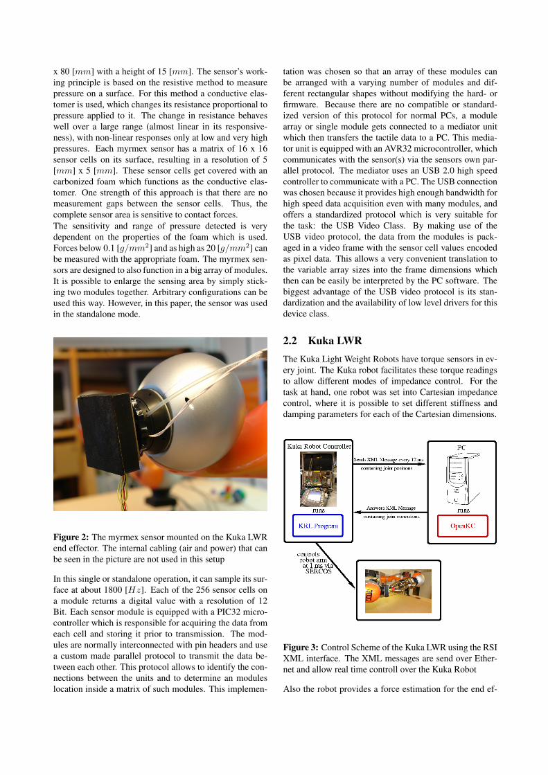
2.2 Kuka LWRThe Kuka Light Weight Robots have torque sensors in ev-ery joint. The Kuka robot facilitates these torque readingsto allow different modes of impedance control. For thetask at hand, one robot was set into Cartesian impedancecontrol, where it is possible to set different stiffness anddamping parameters for each of the Cartesian dimensions.
Figure 3: Control Scheme of the Kuka LWR using the RSIXML interface. The XML messages are send over Ether-net and allow real time controll over the Kuka Robot
Also the robot provides a force estimation for the end ef-

fector. The forces on the end effector are calculated withthe use of a dynamic model of the robot and the torquereadings within the Kuka controller [1]. The force estima-tion is used to establish an ongoing contact force betweenthe myrmex sensor (which is mounted on the end effector)and the material probe.The robot arm is controlled in real-time using Kukas RSI-XML interface on the robots side and our own implemen-tation of the provided interface of the controlling server,the OpenKC software package. The communication be-tween the robot controller and, in out case, a PC runninga highly preemptive Linux kernel, is done via TCP/IP overEthernet. The robot sends an XML message with its actualpositions, torques and estimated forces, the server softwarereads out the transmitted data and will send a responsepacket to the robot controller. In the response packet, acorrection for either the joint values or the Cartesian posi-tion is send to the robot. The robot will generate packetsin a 12 [ms] interval, and the server needs to answer withinthis time period. An overview of the architecture can befound in Figure 3.The Cartesian correction mode does not allow the gener-ation of movements that take advantage of the redundantjoint of the robot. The inverse kinematics on the Kuka con-troller is up to the date of writing not able to take advantageof the additional degree of freedom. Also, since the Kukacontroller will always have its own inverse kinematics run-ning in RSI-XML mode, it is not possible to drive the robotthrough a (6-DOF) singular configuration, even when therobot is controlled in joint space.
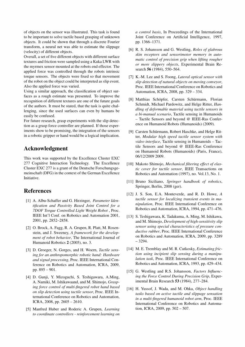
Figure 4: The five objects that were probed, smooth sideof a mouse pad, a wooden surface, the cover of a book, therough side of a mouse pad as well as a ceramic cup.
To do Cartesian space control and at the same time tak-
ing advantage of the redundant DOF, we use a C++ imple-mentation of the Control Basis Framework [5, 2]. Thisframework provides flexible means to synthesize closedloop controllers from simple components: Artificial poten-tial functions, sensor transforms, effector transforms andresources.Sensor transforms map actuator sensor readings (joint po-sitions) into the task space of interest (e.g. Cartesianspace).Additionally the control basis framework allows for hier-archical composition of controllers. This is achieved bymeans of manipulator Jacobian null space projection [11].We use in our use case a subordinate controller which willavoid singular configurations and joint limits.
3 ExperimentsTo have a sound data basis for the slip detection algo-rithm, the described setup was used to record a number ofstick/slip conditions. A total of five different surfaces (cf.Figure 4) was probed: a book cover, a wooden surface, aceramic cup, the smooth surface of a mouse pad and therough rubber side of the mouse pad.
0
5000
10000
15000
20000
25000
30000
35000
40000
0 100 200 300 400 500 600 700 800 900
Pow
erle
vel
Frequency
Book cover, stick conditionBook cover, slip condition
Figure 5: The graph shows the spectrum of two samples.Both samples come from the same experiment. The sam-pled object is the book cover. A clear distinction betweena slip and stick condition can be made.
Each object was sampled five times. During the samplingprocedure, at first, contact with the object was establishedand a contact force of 0.8 [N ] was maintained. Afterward,the end effector was moved to three further positions onthe material. The positions were aligned in a square, witha short resting phase of approximately one second at eachcorner. In a subsequent run, the same square was sampledwhile maintaining a force of 2 [N ]. During the run, thetactile data from the myrmex sensor as well as the posi-tion and force information of the robot were recorded. The

recording frequency was run in sync with the robots in-terpolation cycle at 83 [Hz]. The software to record themyrmex tactile data run in a parallel thread saving all tac-tile frames coming from the sensor. Therefore it was possi-ble, for each frame recorded in sync with the robots updatefrequency, to tag the last 1800 tactile frames to the robotsmovement during this cycle.
3.1 Data Processing
Each recorded sample (tactile data and robot movements)was processed as one data point. To transfer the tactiletime series from the time to the frequency domain, a onedimensional fast Fourier transform (FFT) was done. TheFFT is an efficient way to compute the discrete Fouriertransform of a given data set. Since we are looking at finitelength signals and different window length - which nat-urally limits the Nyquist frequency - leakage and aliasingeffects have to be taken into account. Also the rubber foamof the myrmex sensor impairs the analysis of the "true"spectrum [10]. Despite these limitations, a qualitative andquantitative differences in the spectrum between slip andstick conditions can be found. In Figure 5 the frequencyspectrum of a stick and a slip condition is shown as a typ-ical example. In this case, the disparity is evident, it hasto be said though that with other samples and materials thedifferences are sometimes not that clear anymore.
0
0.002
0.004
0.006
0.008
0.01
0.012
0.014
0 100 200 300 400 500 600 700 800 900
Pow
erle
vel
Frequency
Book cover, slip condition normalizedCeramic Cup, slip condition normalized
Slick side mousepad slip condition normalizedWooden surface slip condition normalized
Figure 6: In this graph, the averaged and normalized fre-quency spectra of different surfaces are exemplary shown.To enhance the readability only four of the five differentmaterials are displayed.
The frequency spectra of the different materials during slipgive cause to the assumption that a material classificationof the surface, although a challenge, can be done. The nor-malized and averaged power levels of the different materi-als during slip can be seen in Figure 6.
3.2 Classification Architecture
0.036
0.038
0.04
0.042
0.044
0.046
0.048
0.05
0.052
0.054
0.056
0 50 100 150 200 250 300
Mea
n S
quar
e E
rror
Number Input Neurons
FFT-Window 256 TestFFT-Window 512 Test
FFT-Window 1024 Test
Figure 7: Classification results for different window sizesw and number of input neurons n.
To show the feasibility of our approach and the ability ofthe tactile sensor pad to serve as a conjunction of a staticand a dynamic tactile sensing device, a standard artificialneural net was trained to detect slippage. A first parame-ter of this approach is the window size w of the FFT as ithas impact on the frequencies that are detectable and thepossible input dimension. In a subsequent step, the result-ing spectrum was divided into n frequency bands of equalsize. Also, the input had to undergo a normalization step,where two different methods were tested: a predeterminedconstant scaling factor and a "dynamic" normalization withthe "DC" element (the Null-frequency part) of the FFT. Inthe following, normalized will refer to the dynamic nor-malization. If not stated elsewise, a constant scaling wasdone. If not stated different, a n–20–1 neural net was used.The answer of the neural net is the (estimated) slipping ve-locity.
4 Results
4.1 Slip Detection TaskThe recorded data was arbitrarily divided into a trainingand a test set. For the window size w, the values 256,512 and 1024 were tested, for the number of frequencybands and therefore the number n of inputs. A total often different values for n in the range 2..256 where used.For each set of parameters, five randomly initialized neuralnets were trained and then tested. For all results, the meansquare error (MSE) was calculated:
MSE(X) :=1n
n∑i=1
(f(xi)− yi)2 (1)

The error on the test data set showed not to benefit fromvalues n ≥ 20. Obviously, the additional neurons on theinput layer lead to over-fitting effects which have a nega-tive impact on the test error (cf. Figure 7).
0.015
0.02
0.025
0.03
0.035
0.04
0.045
0.05
0.055
0.06
0 50 100 150 200 250 300
Mea
n S
quar
e E
rror
Number Input Neurons
FFT-Window 256 TestFFT-Window 256 TrainFFT-Window 1024 Test
FFT-Window 1024 Train
Figure 8: Classification results including training and testerrors for different window sizes w.
In Figure 8 a comparison of the training and testing setwith different window sizes can be seen. A larger win-dow size significantly improves the classification rate onthe training set, but at the same time reduces the general-ization of the net.
0.036
0.038
0.04
0.042
0.044
0.046
0.048
0 50 100 150 200 250 300
Mea
n S
quar
e E
rror
Number Input Neurons
Normalized FFT-Window 256 TestNormalized FFT-Window 512 Test
Normalized FFT-Window 1024 Test
Figure 9: The five objects that were probed, smooth sideof a mouse pad, a wooden surface, the cover of a book, therough side of a mouse pad as well as a ceramic cup.
Interestingly the results for the dynamic normalization re-verse the previous findings. While for the window size of256 and 512 samples almost equal error rates, the best re-sults are at a window size of 1024. Also, the classification
error is overall lower than in the fixed factor normalization.For details, see Figure 9.
4.2 Material Classification Task
For the material classification task a n-15-5 neural net wasused, with the window size w fixed at 1024. Although per-fect classification on the training set could be obtained, thetest error was unsatisfactory. In Figure 10 the test resultsare summarized.
10
15
20
25
30
35
40
45
50
55
60
0 50 100 150 200 250 300
Cor
rect
Mat
eria
l Cla
ssifi
catio
n [%
]
Number Input Neurons
Normalized InputFixed Scaling Input
Figure 10: In this graph the correct classifications of thematerial surface texture are plotted. In this even for hu-mans difficult task, a good generalization could not beachieved.
When taking a closer look at the confusion matrix, whichcan be found in Table 1, one can find that very distinct sur-faces like the ceramic cup, which is significantly smootherthan all the other surfaces, is classified quite well.
book mp rh mp sh cup woodbook 8.5% 0% 1.0 % 2.8 % 12.4 %
mp rough 1.9 % 18.0 % 8.5 % 0.0 % 0.0 %mp smooth 0.0 % 9.5 % 8.5 % 0.0 % 1.9 %
cup 0.0 % 0.0 % 0.0 % 6.6% 0.0 %wood 0.0 % 0.0 % 11.4 % 0.0 % 8.5 %
Table 1: Confusion matrix of the material classificationtask. The rows represent the answer from the neural netwhereas the columns stand for the true class. The diagonalentries are the correct classifications.
5 Conclusions and OutlookThe authors presented a piezo-resistive high-speed tac-tile sensor pad (myrmex) that enables researchers to sensestatic and dynamic tactile events. To demonstrate the vari-ability of the sensor, a method to detect incipient slippage
of objects on the sensor was illustrated. This task is foundto be important to solve tactile based grasping of unknownobjects. It could be shown that through a discrete Fouriertransform, a neural net was able to estimate the slippage(velocity) of different objects.Overall, a set of five different objects with different surfacetextures and friction were sampled using a Kuka LWR withthe myrmex sensor mounted at the robots end effector. Theapplied force was controlled through the robots intrinsictorque sensors. The objects were fixed so that movementof the robot on the object could be interpreted as slip event.Also the applied force was varied.Using a similar approach, the classification of object sur-faces as a rough estimate was presented. To improve therecognition of different textures are one of the future goalsof the authors. It must be stated, that the task is quite chal-lenging, since the used surfaces can even by humans beeasily be confused.For future research, grasp experiments with the slip detec-tion as a grasp force controller are planned. If those exper-iments show to be promising, the integration of the sensorsin a robotic gripper or hand would be a logical implication.
AcknowledgmentThis work was supported by the Excellence Cluster EXC277 Cognitive Interaction Technology. The ExcellenceCluster EXC 277 is a grant of the Deutsche Forschungsge-meinschaft (DFG) in the context of the German ExcellenceInitiative.
References[1] A. Albu-Schaffer and G. Hirzinger, Parameter Iden-
tification and Passivity Based Joint Control for a7DOF Torque Controlled Light Weight Robot , Proc.IEEE Int’l Conf. on Robotics and Automation 2001,2001, pp. 2852–2858.
[2] O. Brock, A. Fagg, R. A. Grupen, R. Platt, M. Rosen-stein, and J. Sweeney, A framework for the develop-ment of robot behavior, The International Journal ofHumanoid Robotics 2 (2005), no. 3.
[3] D. Groeger, N. Gorges, and H. Woern, Tactile sens-ing for an anthropomorphic robotic hand: Hardwareand signal processing, Proc. IEEE International Con-ference on Robotics and Automation, ICRA, 2009,pp. 895 – 901.
[4] D. Gunji, Y. Mizoguchi, S. Teshigawara, A.Ming,A. Namiki, M. Ishikawaand, and M. Shimojo, Grasp-ing force control of multi-fingered robot hand basedon slip detection using tactile sensor, Proc. IEEE In-ternational Conference on Robotics and Automation,ICRA, 2008, pp. 2605 – 2610.
[5] Manfred Huber and Roderic A. Grupen, Learningto coordinate controllers - reinforcement learning on
a control basis, In Proceedings of the InternationalJoint Conference on Artificial Intelligence, 1997,pp. 1366–1371.
[6] R. S. Johansson and G. Westling, Roles of glabrousskin receptors and sensorimotor memory in auto-matic control of precision grip when lifting rougheror more slippery objects, Experimental Brain Re-search 56 (1984), 550–564.
[7] K.-M. Lee and S. Foong, Lateral optical sensor withslip detection of natural objects on moving conveyor,Proc. IEEE International Conference on Robotics andAutomation, ICRA, 2008, pp. 329 – 334.
[8] Matthias Schöpfer, Carsten Schürmann, FlorianSchmidt, Michael Pardowitz, and Helge Ritter, Han-dling of deformable material using tactile sensors ina bi-manual scenario, Tactile sensing in Humanoids– Tactile Sensors and beyond @ IEEE-Ras Confer-ence on Humanoid Robots (Humanoids) (2009).
[9] Carsten Schürmann, Robert Haschke, and Helge Rit-ter, Modular high speed tactile sensor system withvideo interface, Tactile sensing in Humanoids – Tac-tile Sensors and beyond @ IEEE-Ras Conferenceon Humanoid Robots (Humanoids) (Paris, France),06/12/2009 2009.
[10] Makoto Shimojo, Mechanical filtering effect of elas-tic cover for tactile sensor, IEEE Transactions onRobotics and Automation (1997), no. Vol.13, No. 1.
[11] Bruno Siciliano, Springer handbook of robotics,Springer, Berlin, 2008 (ger).
[12] J. S. Son, E.A. Monteverde, and R. D. Howe, Atactile sensor for localizing transient events in ma-nipulation, Proc. IEEE International Conference onRobotics and Automation, ICRA, 1994, pp. 471–476.
[13] S. Teshigawara, K. Tadakuma, A. Ming, M. Ishikawa,and M. Shimojo, Development of high-sensitivity slipsensor using special characteristics of pressure con-ductive rubber, Proc. IEEE International Conferenceon Robotics and Automation, ICRA, 2009, pp. 3289– 3294.
[14] M. E. Tremblay and M. R. Cutkosky, Estimating fric-tion using incipient slip sensing during a manipu-lation task, Proc. IEEE International Conference onRobotics and Automation, ICRA, 1993, pp. 429–434.
[15] G. Westling and R.S. Johansson, Factors Influenc-ing the Force Control During Precision Grip, Exper-imental Brain Research 53 (1984), 277–284.
[16] H. Yussof, J. Wada, and M. Ohka, Object handlingtasks based on active tactile and slippage sensationin a multi-fingered humanoid robot arm, Proc. IEEEInternational Conference on Robotics and Automa-tion, ICRA, 2009, pp. 502 – 507.