
Using a Digital Camera to Photograph slabs, cabs, … · Using a Digital Camera to Photograph...
30
1 Using a Digital Camera to Photograph slabs, cabs, gem- stones, minerals and jewelry - Parts I - X by ron gibbs Stone Canyon Jasper Cabochon Calcite Crystal Citrine, Rose de France (Amethyst), Ametrine Gaspeite, jasper, opal in sterling silver Over the next several months I will be writing a series of articles on using digital cameras to capture items related to our hobby. I now have a ready supply of material since I am just finishing the preparation for teaching a class in the topic at William Holland Lapidary School. My company bought me a Mac II color computer in 1987 and I saw what real color digital images could look like, wow, I was impressed. I was a very early user of digital cameras, the first one that I used (notice I did not say owned, again my company bought one for me to evaluate) was from Panasonic, and dated back to 1989 - 1990. They produced a digital still camera with something like 320 x 240 pixels of resolution for the price of only $2500. It used, small, roughly 1 inch floppy disks to save the images in almost real time. Color photos, well not at this time and price point. In 1990 I managed to get a copy of Photoshop with the PhotoMat icon and began to play with digital images, I closed down most of my per- sonal “wet chemistry” darkroom that same year as I believed I saw the future, and it was digital photography. In 1994 I got my hands on my second digital camera, the Apple Quick- take camera which doubled the resolution to 640x480 pixels and could save 8 full size images for only $750. And it had Color! How could things get any better? It has taken about 20 years for the digital camera to achieve the same general resolution as film, but digital editing (Photoshop) provided advancements in image control never fully realized by the “wet chem- istry darkroom”. I spent much of my time developing digital techniques to adapt to science since I was once a chemist with a strong interest in photography.
Transcript of Using a Digital Camera to Photograph slabs, cabs, … · Using a Digital Camera to Photograph...

1
Using a Digital Camera to Photograph slabs, cabs, gem-stones, minerals and jewelry - Parts I - X by ron gibbs
Stone Canyon Jasper Cabochon
Calcite Crystal
Citrine, Rose de France (Amethyst), Ametrine Gaspeite, jasper, opal in sterling silver
Over the next several months I will be writing a series of articles on using digital cameras to capture items related to our hobby. I now have a ready supply of material since I am just finishing the preparation for teaching a class in the topic at William Holland Lapidary School.
My company bought me a Mac II color computer in 1987 and I saw what real color digital images could look like, wow, I was impressed. I was a very early user of digital cameras, the first one that I used (notice I did not say owned, again my company bought one for me to evaluate) was from Panasonic, and dated back to 1989 - 1990. They produced a digital still camera with something like 320 x 240 pixels of resolution for the price of only $2500. It used, small, roughly 1 inch floppy disks to save the images in almost real time. Color photos, well not at this time and price point.
In 1990 I managed to get a copy of Photoshop with the PhotoMat icon and began to play with digital images, I closed down most of my per-sonal “wet chemistry” darkroom that same year as I believed I saw the future, and it was digital photography.
In 1994 I got my hands on my second digital camera, the Apple Quick-take camera which doubled the resolution to 640x480 pixels and could save 8 full size images for only $750. And it had Color! How could things get any better?
It has taken about 20 years for the digital camera to achieve the same general resolution as film, but digital editing (Photoshop) provided advancements in image control never fully realized by the “wet chem-istry darkroom”. I spent much of my time developing digital techniques to adapt to science since I was once a chemist with a strong interest in photography.

2Porcelean Jasper (aka Scifi Jasper, Exotica Jasper, etc. etc. )
I will break up the future articles into the following main topics and proceed accordingly. There will likely be more than one article devoted to each topic.
1.) The Camera - what are the minimal requirements of a camera to pro-duce reasonable digital images from the afore mentioned subjects.
2.) The Camera Controls - what are the most important settings, and why select them for virtually all of the photography.
3.) Lighting - the often overlooked critical element in taking the photo-graphs - the “Color” of light, the quality of light and its placement.
4.) Lighting setups for each of the subject types, and backgrounds
5.) Adobe Photoshop or Adobe Elements for editing the photos and get-ting the most from each image. Which tools are easy and fast for most users.
6.) What can I do with all these images now that I have created this li-brary of photos?
So let’s begin with camera specifications for use in close-up digital im-ages of lapidary materials. 1.) The Camera Specifications -
We may as well start with the number one marketing topic for digital cameras ... Resolution. This seems to be the topic most often discussed when describing a digital camera and, what makes it better than another. In reality it has become one of the least important topics for most cam
era users. Notice I highlighted the word “marketing”, it has become more of a marketing gimmick than a useful function for sometime.
Resolution is given in terms of total pixels, we have 2 mega pixel (MP = millions of pixels) cameras, 4 MP, 8 MP up to about 20 MP today. The resolution you need is solely dependent upon the final use of the image.
There are generally two uses for images, they can be used to display on a monitor (WEB, e-mail, pdf based newsletter, or slideshows.)
For this use, most computer moni-tors display 1024 x768 pixels of resolution, that’s less than 0.8 MP! If we want to show full resolution slides on our high definition TV, it is now 1912 x 1080 pixels for full screen, or only slightly over 2 MP off total resolution.
For users who do not want to print images, and only want to electroni-cally display them at high quality, they rarely need more than 4 to 5 MP of resolution. Try to find a digi-tal camera with that low of resolu-tion today.
For those interested in printing pictures, you do need more resolu-tion. It’s actually because all of the printing technologies have to use patterns of dots to create a full spectrum of colors. This technique, called dithering, requires more pixels to achieve the same visual resolution that a monitor does.
At the low end of the scale, you need abut 2 MP to create a reason-able 8 inch by 10 inch print. If you

3
35mm lens 70mm lens macro lens
Stamp with 35mm lens
Stamp with 70mm lens
Stamp with Macro lens
want the best possible 8x10 print then about 8 MP is recommended. If you are going to print enlarge-ments that are 11x14 or 16x20 inches in size, then higher resolu-tion camera may be the ticket for you.
For most people, non-photo pros, 8-10 MP is over kill as far as reso-lution is concerned.
So what else is important for shoot-ing close-up images? The camera needs “macro” capability. “Macro” means that the camera can “fill the frame” with the subject. Digital images cannot be blown up beyond their highest original resolution without loss in image quality.
Lets look at the examples to the
left. Each photo is full frame and is about 3000 x 2000 pixels of total resolution. In the first image the stamp is roughly 228 x 174 pixels in total size. In the second image it is 670 x 510 pixels in size, and in the last image it is 1500 x 1150 pixels in size.
Notice the resolution/quality differ-ence in the three blow-ups above. The first is with the 35mm lens, the second with the 70mm and the final image is with the macro. Sharp-ness is best obtained when you fill the frame with the image and get as many original pixels as possible in the photo - so the general rule for digital images - always fill the frame!
Next month we’ll look at focus, and shutter speed.

4
Macro Mode
Macro Mode - but “zoom” in wrong po-sition and therefore NO focus possible
Macro Mode - “zoom” now in accept-able range - macro will now focus prop-erly. The flower has changed from white to yellow in this image.
Typical Self-Timer Icon
Using a Digital Camera to Photograph slabs, cabs, gemstones,minerals and jewelry - Part II by ron gibbs
Over the next couple of installments I will discuss what I believe are the most important features to obtain when you purchase a digital camera for Lapidary related close-up work on the WEB or in print.
In Part I, I ended with the general rule of “fill the frame” with the image. Digital images cannot easily be enlarged above their original size without image detail loss. Thus high on the feature list for jewelry, cabochons, gemstones, slabs, etc. is MACRO FOCUS on the camera. To achieve highly detailed images you must fill the frame with the material being photographed and that means focusing close to the subject matter.
Today most digital cameras have a “macro” mode and it is often desig-nated as a small “flower icon” (fig. 1) somewhere on one of the many controls. Typically the focal distance runs from about 1 to 3 inches out to about 8-10 inches. It may vary depending on the “zoom” setting of the lens.
When the lens is set to it’s wide angle setting, it will typically be in the 1-3” range and when set to ore of a telephoto setting it’s likely to be in the 6-10 inch range. (Important NOTE! - many times the macro setting will only focus throughout a narrow band of the zooming range.)
This means once the macro function is turned on, the zoom must be ad-just to a certain narrow range where close focus is possible. Some manu-facturers show the flower icon in the view finder as you try to focus and when the proper focus can be achieved, the flower changes color. Look in the camera manual to see if this is true for your camera or you will NOT be able to achieve focus no matter how hard you try. (See figure 2.)
So, item one on our purchase list is a macro capability in the lens. I prefer a lens that will focus successfully at about 3” out to 8” and fill most of the frame with the photographed object. If your camera focuses at the 1 to 2” range only, it may be hard to get lighting into the subject as there is little space between it and the lens.
This brings me to the next point on focus. Most of today digital cameras can be divided into two “AUTO-FOCUS” categories, passive auto and active auto.
Active focus systems use a secondary beam of light, infra red or in rare cases sound to achieve the focus. They measure the time it takes to send the beam out to the object and then return to he camera sensor. The time is proportional to the distance and they set the focus accordingly. These type of systems have a few problems build-in. First if there is something

5
transparent between the camera and the object (like a clear window) the camera will tend to focus on the window pane and not the object. In the case of IR (infra red) sensors they can be fooled by heated objects in the scene or by objects that absorb large amounts of infra red radiation.
The Passive focus systems use software in the camera and examine the image on the ccd (or equivalent sensor) in the camera and determine fo-cus by the contrast in the image. Sharp lines are sharp because they have high contrast. Thus the software determines the best spot to focus on by the area in the image with the best (read that as highest) contrast. Unfor-tunately this is not always the part of an object you may want in focus. Take of example a piece of jewelry, a rounded cabochon in the center my not have enough to contrast to force the auto-focus to find it if the is sharp wire work or edges around the rear surface of the jewelry piece. Hence the cab may always appear out of focus while the wire work is sharp. Continuous tone, similar hues, and flat objects without shading may con-fuse this type of focusing system,.
Another nice feature in a digital close-up camera is “MANUAL FOCUS”. It is possible to work around the lack of manual focus, but it’s really handy if you are doing large quantities of macro work.
Also the next topic goes hand-in-hand with focus, and that is tripping the shutter (taking the picture). In order to get crisp, sharp images the camera must be maintained rock steady. This means the use of a tripod, either table top or floor standing for all of our shooting. Buy a sturdy tripod, not a little thin, flimsy one.
When a camera is mounted on a tripod via the tripod mounting screw in the base of the camera, it is best to actually take the exposure by using either the self-timer on the camera (virtually all of toady’s digital cameras have them. OR if available, buy a remote shutter release to fire the cam-era. Many of the current digital camera’s have either IR remote controls or manual remote with a wire tether. Either will work. If they are not available then use the self-timer to actually take the image.
At first glance images shot hand-holding or on the tripod using your finger will look fine in the camera view-finder or in most camera LCD display screens. When the image is finally transferred to the computer to look at it full size it will likely look far less sharp when blown up if taken hand-held or with your finger on the shutter release (even on the tripod). The three images to the right show the result of lowing up part of the cabochon shot using the three methods.
Fig 3. - Image hand held and enlarged - very large loss of detail in the photo. Fig 4. the camera on a tripod but the shutter pressed by a finger. There is still some degree of blur in the blown up image. The last in the sequence, Fig, 5, was captured using the self-timer and the detail is sharp.
Cabochon Photograph
Fig. 3
Fig. 4
Fig. 5
6
The list has now grown to begin the selection of a digital camera with features most likely to aid in close-up photography.
1.) Macro -focus to boost the size of the image and apply the largest number of pixels possible.
2.) Manual control of focus to se-lect the specific part of the image to maintain in sharp focus.
3.) Self-timer and/or remote shutter release to use to take the picture to avoid camera shake and maintain a crisp image. (Although not part of the camera - a good tripod is also a necessity for a sharp image.)
Next month I will discuss the expo-sure part of taking a proper im-age, the need for f-stop (aperture) control, the best shooting mode, and how the camera determines the exposure, and why it can be wrong.
(Continued info on auto-focus) -some work arounds -If the camera you have does not have MANUAL focus there are a couple of potential work-arounds you may try in order to achieve the control of focus you need. The first one can be implemented easily if you have a remote release mecha-nism.
Most of the current digital cam-eras run through the same general procedure just before they actually expose the image. They re-check the exposure if in auto-mode, and they RESET the FOCUS (in auto focus) just before they actually take the picture. This auto-RESETTING OF FOCUS is what may change the desired focus point. Most of the
current crop of digital cameras can be made to auto-focus and HOLD the focus by HALFWAY depress-ing the shutter release button and holding it in that halfway position.
While holding the button in the half way position you can move the object very slightly toward or away from the camera to achieve the desired focus. It’s not easy, but it can be done. Once the object is moved to the correct position, the shutter is fully depressed finishing the exposure.
It is a little difficult using the LCD plate to determine the focus, but it can be done with practice on most cameras while the shutter is half-depressed. You have to look at the image in the LCD while manipu-lating the object and continuing to hold the shutter in the half-de-pressed position.
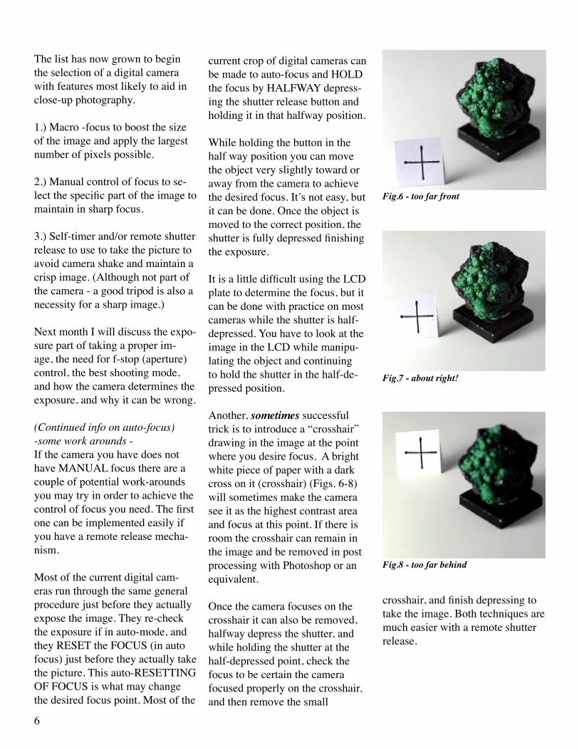
Another, sometimes successful trick is to introduce a “crosshair” drawing in the image at the point where you desire focus. A bright white piece of paper with a dark cross on it (crosshair) (Figs. 6-8) will sometimes make the camera see it as the highest contrast area and focus at this point. If there is room the crosshair can remain in the image and be removed in post processing with Photoshop or an equivalent.
Once the camera focuses on the crosshair it can also be removed, halfway depress the shutter, and while holding the shutter at the half-depressed point, check the focus to be certain the camera focused properly on the crosshair, and then remove the small
Fig.6 - too far front
Fig.7 - about right!
Fig.8 - too far behind
crosshair, and finish depressing to take the image. Both techniques are much easier with a remote shutter release.

7
Using a Digital Camera to Photograph slabs, cabs, gemstones,minerals and jewelry - Part III by ron gibbs
Picking up this month we’ll look at some things related to proper expo-sure, and those features I think are important for a camera that is be-ing used for close-up photography. Three items immediately come to mind, the control of the f-stop (sometimes called the aperture, iris, or diaphragm), the best exposure mode to use for most close-up work, and finally how the camera actually calculates exposure.
Proper exposure is obtained by balancing three things in photography. The “intensity of the light” striking the sensor (or film), the “duration of time” it strikes the sensor, and the “sensitivity” of the sensor. For now we’ll assume the sensitivity of the sensor (ISO value or ASA speed) is going to be a constant value. When this value is constant then the ratio of light intensity and duration control the exposure.
Light intensity is controlled by a “light valve” (a mechanical iris) which in effect is a variable size hole. When a lens allows all of the light to pass that it can, the lens is said to be operating at its native aperture or highest speed. The lens in figure 1 is shown “wide open” at its native aperture. When the iris is reduced, it allows less light to pass through the lens and effectively makes it slower. Figure 2 shows an iris partially closed.
Aperture is measured as a function of the diameter of a lens verses its fo-cal length. Thus a 50 mm diameter lens with a 50 mm focal length would have an aperture value of f/1.0. If the iris is reduced to allow only one half as much light to pass, then the f-stop of the lens would be f/1.4. So where do the weird numbers come from? Turns out that the amount of light passing through the hole is really a function of the size (or area) of the hole. The area of a circular hole can be calculated by the formula Area = pi x r2 (pi times the radius squared). Thus a hole that allows one half the light so pass will be related to the square root of area, r = √ A/pi (since pi is a constant value we can forget it while doing comparisons.)
Thus the table of f-stops looks like figure 3 and is actually based on the area of the circle involved in the iris. It’s too hard for us to remember the precise values so we round them off to the f-numbers. Controlling the f-number provides the close-up photographer with one very important tool. Not only is it one half of the exposure control, but the higher the f-number (the smaller the hole size) the greater the “depth of focus” of the image.
As an object gets closer to the lens, it has a shorter range of focus. This range of focus is often described as the “depth of field,” or the total range of sharp focus in front and behind the primary object. In macro photog
figure 1.
figure 2.
Light Ratio
f-stop square roothole area
1:1 f/1.0 1.01:2 f/1.4 1.41421:4 f/2.0 2.01:8 f/2.8 2.82841:16 f/4 4.01:32 f/5.6 5.65681:64 f/8 8.01:128 f/11 11.31371:256 f/16 161:512 f/22 22.6274
figure 3.

8
raphy the depth of field can be measured in fractions of an inch in many cases. For this reason it is desirable to use a high f-number whenever close-up work is being done. The f-stop of the camera should be set to a minimal value of f/8 and f/11 through f/22 may be more desirable. Thus we have a new requirement for our digital camera. The camera should have independent f-stop control and should reach at least f/8 and higher values are better.
This usually means that the desired camera will also have what is called an “aperture” controlled exposure mode. This means that the photogra-pher pre-selects the f-stop value and the camera will auto-calculate the proper exposure time. Because low f-stops often mean longer exposure times, it is necessary to use the tripod or other camera steadying tech-niques in lost cases. As described in the previous articles, tripods and remote shutter releases are priority items for the camera.
Let’s examine this “depth of field” phenomena. Look at the figures 4 - 7, the first image was captured with the f-stop set to f/5.6 and the screw at the 17” mark was the primary focus point. Notice that the number 18 is totally out of focus, but as the f-stop increases down the range of figures the area in front and behind the primary focus is sharper. Thus for close-up work the camera needs to be set to a fixed f-stop between f/8 and f/22 to get the most depth of field.
The camera should have an “aperture priority” mode so the photographer can set the desired f-stop and the camera will then select the needed shut-ter speed to make the correct exposure. This assumes that the ISO equiv-alent setting is the lowest the camera supports. Typically between 50 and 200. In the digital world, the ISO value is not he same for all cameras, but the lowest setting is always the best for each variety. When film was in use, a faster film speed (higher ISO or ASA value) always produced more grain in the image. Thus ASA 400 film could be used in low light situa-tions, but the image often had a sandy texture. This was the cost of using faster film.
Today, the higher ISO speed means that the camera sensor is set to more sensitivity. This will result in an image with more “digital noise.” Digital noise shows up as lower contrast images, often with strange color spots randomly around the image. Sometimes the images show a color band along a very strong contrast area or edge. It is the equivalent of the old film grain. Most digital cameras are acceptable up to about ASA 400, but degradation begins at higher values. Some cameras are more forgiving and some are less so. As a general rule set the camera to the lowest ASA value in its range.
So are there any other features which can help with exposure in a digi-tal camera? The answer is yes, a nice feature is “fine exposure control” sometimes referred to in the camera manual as Ev control.
figure 4.
figure 5 .
figure 6.
figure 7.

9
Cameras can be fooled fairly easily when doing close-up images. Their exposure mechanism is designed to give proper exposure for an “average photo.” So what is an average photos? In general camera exposure sys-tems read the entire image and it will yield about 18% gray when all the pixels are averaged together. Once again this comes from the film days of photography and it assumes that the photo is an average snap-shot. That is, it contains some sky, some ground, a few points of interest and that it’s about mid-day. That’s why many of today’s cameras have multiple ex-posure methods that can be turned off or on, like sunset, night time, back lighting, snow, etc.
When we go most jewelry or close-up work the exposure is often fooled because we tend to use overly dark or over light backgrounds to make the jewelry stand-out. Thus if we place the jewelry on a true black back-ground, the image has too much black and the camera will compensate to make the overall exposure about 18% gray. Thus the jewelry piece often comes out too light and the background looks gray and not black. See figure 8. The camera exposure system is fooled by the large area of black in the background. If the camera has Ev settings (exposure compensation) then the they can be adjusted to make the background appear black and gem or jewelry comes out properly exposed. Figure 9 Ev setting of Ev = -1.3.
The same, but opposite, effect happens when the background is white fig-ure 10. The exposure meter is fooled and tries to make the overall image darker, by compensating for the white background. Again the background turns gray and this time the jewelry or gemstone is too dark. Once again by adjusting the Ev setting the image can be corrected. (Figure 11.)
To summarize this month, the features set that makes a camera a good selection for close-up photography should also include ...Adjustable f-stops (f/8 or higher)Aperture priority exposure modeEv control (exposure compensation control)Add to them the desired features from last month ...about 5 or more mega-pixels of resolutionMacro focus mode (fill the frame)Self-timer or remote shutter release (steady exposure)Manual focus (this one can be worked around)and a steady tripod.
Next month we’ll look at the final feature that make a camera a good candidate for close-up photography; white balance control. We’ll then discuss the typical set up for the camera. Once the camera is set up and ready to shoot, most of what needs to be done is proper lighting. The camera set up and controls stay 95% the same for all close-up images, with the exception of a little Ev adjusting depending on the background. Once the camera is defined, we’ll spend nearly all the rest of the time discussing lighting to get the best look.
figure 8.
figure 9.
figure 10.
figure 11.

10
Using a Digital Camera to Photograph slabs, cabs, gemstones,minerals and jewelry - Part IV by ron gibbs
This will be the last installment of information that describes the useful features in a camera for close-up photography, next month we’ll con-tinue with lighting and setups. So this month we’ll look at color. Color is important if want our images to closely resemble the objects being photographed, although there are people out there marketing and selling “green” amethyst, I think amethyst by definition should look purple.
Light has two important descriptive properties with regard to photogra-phy, first it has a Color (or Hue) and second it has what I will refer to as Texture (hard or soft). The color of light is usually described by a name, thus words like red, yellow, blue, orange, purple, violet, etc. describe a specific hue or color. The computer world and digital camera world live in what we call RGB space. All colors can be defined as mixtures of red, green, and blue light. (Fig. 1.)
Equal parts of Red and Green produce Yellow, equal parts of Green and Blue produce a pale blue called Cyan, and equal parts of Red and Blue produce hot pink called Magenta. The thing that surprises people is that equal parts of all three R, G and B produce WHITE. All colors come from what we know as White. True white has equal portions of all colors, or another way to think of it is that white light contains all the colors in the rainbow. When we see a red object it is because the white light illuminat-ing it has had the green and blue portions removed, leaving behind the red color.
We can also measure the color of light by something called its tempera-ture. There is a temperature scale called the Kelvin scale which can be use to describe the color of light. Low color temperature are at the red end of the scale. A description of the scale is illustrated in the table of figure 2. As you can see even “daylight” can and does have different color temperatures. It can be warm (red-yellow) to bluish depending on the time and weather conditions.
The color of objects in a scene are dependent upon two things, their inherent color (what part of the spectrum they reflect) and the color of the light source illuminating them. We’ll examine several possible cases in the next set of diagrams to get an idea of how tough it might be to get correct color. Most of the digital cameras on the market today have color balance settings built-in (typical Fig. 3), but not all have a “manual” color correction, many have automatic or a series of specific color corrections that can be selected. For precise close-up work a manual color correc-tion is desirable, but not absolutely necessary as long as the camera has at least an auto setting, or you (the photographer) develop very good habits when setting up and shooting your desktop (close-up) photos.
Source degrees KSummer Day - (sun & sky) 6500
Fluorescent Daylight 6500
Xenon (flash) 6400
Overcast Sky 6000
Sunlight (noon) 5400
Fluorescent Daylight 5000
Daylight Flood 4800-5000
Sunlight (Early morning) 4300
Sunlight (1 hour after Dawn) 3500
Photo Flood 3400
Fluorescent Cool White 3400
100 watt Tungsten Halogen 3000
Fluorescent Warm WHite 2950
100-watt incandescent 2870
50-wat incandescent 2500
candle flame 1850-1900
match flame 1700
Figure 1.
Figure 2.
AutoIncandescentFluorescentDirect SunFlashCloudyShadeManual
Figure 3.
11
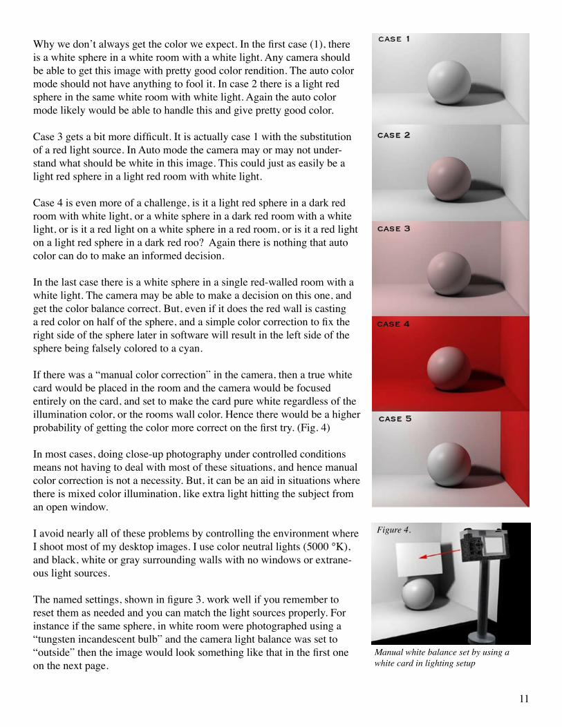
Why we don’t always get the color we expect. In the first case (1), there is a white sphere in a white room with a white light. Any camera should be able to get this image with pretty good color rendition. The auto color mode should not have anything to fool it. In case 2 there is a light red sphere in the same white room with white light. Again the auto color mode likely would be able to handle this and give pretty good color.
Case 3 gets a bit more difficult. It is actually case 1 with the substitution of a red light source. In Auto mode the camera may or may not under-stand what should be white in this image. This could just as easily be a light red sphere in a light red room with white light.
Case 4 is even more of a challenge, is it a light red sphere in a dark red room with white light, or a white sphere in a dark red room with a white light, or is it a red light on a white sphere in a red room, or is it a red light on a light red sphere in a dark red roo? Again there is nothing that auto color can do to make an informed decision.
In the last case there is a white sphere in a single red-walled room with a white light. The camera may be able to make a decision on this one, and get the color balance correct. But, even if it does the red wall is casting a red color on half of the sphere, and a simple color correction to fix the right side of the sphere later in software will result in the left side of the sphere being falsely colored to a cyan.
If there was a “manual color correction” in the camera, then a true white card would be placed in the room and the camera would be focused entirely on the card, and set to make the card pure white regardless of the illumination color, or the rooms wall color. Hence there would be a higher probability of getting the color more correct on the first try. (Fig. 4)
In most cases, doing close-up photography under controlled conditions means not having to deal with most of these situations, and hence manual color correction is not a necessity. But, it can be an aid in situations where there is mixed color illumination, like extra light hitting the subject from an open window.
I avoid nearly all of these problems by controlling the environment where I shoot most of my desktop images. I use color neutral lights (5000 °K), and black, white or gray surrounding walls with no windows or extrane-ous light sources.
The named settings, shown in figure 3. work well if you remember to reset them as needed and you can match the light sources properly. For instance if the same sphere, in white room were photographed using a “tungsten incandescent bulb” and the camera light balance was set to “outside” then the image would look something like that in the first one on the next page.
Manual white balance set by using a white card in lighting setup
Figure 4.

12
The image would appear an orange color as the camera was expecting nearly white light and saw the tungsten light color instead. If the white balance were set properly to tungsten then the image would appear simi-lar to the second one in this series and look roughly correct.
This is as it should be, but if you forget to reset the white balance to daylight and then shoot a daylight image (still with the camera tungsten setting selected) the white image would appear like the third image in the series. It would show a blue cast as the camera would be trying to correct the white daylight to remove an orange cast (normally present in a tung-sten light).
Thus the light balance controls in the camera work fairly well as long as you always remember to set them to the correct light type each time it is used, or set it to auto and hope for now unusual situations (works most of he time), OR manually set it properly for the specific light you are about to use.
Camera feature summary ... if you are purchasing a camera for close-up work look for the following features ... (Compiled in this PDF.)(1) Macro Focus (fill the frame ... June)(2) Manual focus (July)(3) Auto Timer (or remote shutter release ... July)(4) f-stop control (Aperture priority mode ... August)(5) Ev (exposure compensation nice but not necessary ... August)(6) Color Balance (manual mode nice but not necessary ... September)
For nearly all of the close-up work described in the next several issues and all of the materials (cabs, gems, jew-elry, beads, minerals, etc.) that will be covered, the Camera will be set up to function in the same way. Here are the desired camera settings and position.
1.) Set the camera ISO/ASA to the lowest number the camera supports (typically ASA 100 - 200)2.) Put the camera on a steady tripod for ALL exposures3.) Set the Exposure mode to Aperture priority. (you can select the f/stop the camera auto selects the shutter)4.) Select an f-stop of at least f/8, and f/11 or f/16 is better.5.) Set the white balance manually with the lights you are using6.) Fill the frame with the object7.) Manually focus on the most important part of the object8.) Use the self timer or remote shutter release to make the exposure9.) Look at the finished image, adjust the exposure with the Ev controls if needed, then repeat steps 7,8 and 9 until a satisfactory exposure is achieved.
The first 5 steps are typically only done once for any photo session. As long as the lighting does not change then these setting will remain the same. Most of the time only steps 6-9 are done for each new subject matter.
Next month we’ll begin looking a the table top setup and the lighting for most work. We will discuss the second light property, it’s texture.

13
Using a Digital Camera to Photograph slabs, cabs, gemstones,minerals and jewelry - Part V by ron gibbs
There are several types of light that can be used successfully in table top digital photography. The ideal light might be natural sunlight, but it is exceedingly hard to control in the studio situation, and rarely available in the evenings unless you live pretty far north!
Traditionally tungsten based photo-flood lights were/are used in film based photography because there is a film specifically designed to color correct this type of light. Remember from last month that light “color” is mea-sured in degrees Kelvin, with low values associated to red-orange light, and higher values headed toward pure white light. Traditional photo floods have a value around 3400 ºK. Providing a warm orange tone.
While it is possible to use these lights with today’s digital cameras (with white balance set to tungsten) there are some disadvantages. First, for a given amount of light you must use fairly high wattage bulbs. The higher wattage bulbs tend to run quite hot and this limits materials that can be used as diffusers, it heats up the studio, it wastes electricity, and they have a tendency to burn skin when accidentally brushed against.
Halogen lights operate in a similar manor although they tend to provide more light for the same wattage, they also run very hot and show all the same types of disadvantages. They can be tamed to a degree when used with fiber-optic light directors as in microscope use, but they are expensive and not used in larger situations.I believe that the best lighting today is either white balanced fluorescent lights or flash. Both can produce excel-lent color results with minimal color correction needed. Both operate much cooler than the filament type bulbs, and both can be diffused with any number of inexpensive materials. The only real disadvantage to electronic flash is the cost and ease of use.
To get good (consistent) results with a flash set up takes a good deal of practice, and a fairly high expenditure. The flash built-in to most digital cameras is basically useless in all but a few cases, so external units are needed to successfully light most scenes. Studio flash equipment is often as expensive as a camera and can be difficult to “pre-visualize” when used. Under correct use and professional control the results can be excellent. (See most of Jeff Scovil’s work!)
For most of us, the use of medium wattage, color correct, compact fluorescent bulbs are a good choice. They are now inexpensive, have long life times, run relatively cool, and can be obtained with good color balance. After recommending them I have had people show me poor color results, but in nearly all cases I found that the wrong fluorescent bulbs were purchased. Names like “Bright White”, “Cool White”, “Warm White”, etc. are not used consistently throughout the industry and often have a wide color latitude. Always buy bulbs that have a Kelvin
Fluorescent Equivalent Tungsten18-20 watt 75 watt23-28 watt 100 watt29-30 watt 120 watt32-36 watt 130 watt40-42 watt 150 watt55 watt 240 watt85 watt 350 watt

14
to be emitted from around the length of the cylinder models. Thus it is most useful to place these bulbs in a reflector to direct as much light as possible in the direction of the subject matter. Even the inexpensive clamp-on work lights work well, or any old photo-flood fixture with a standard screw socket works fine.
Some sort of frame work is necessary to aid in positioning the reflectors around the subject. A typical lighting set-up for most work will involve 2 or 3 lamps. Thus the reflectors can each have their own independent stands or can be used in some kind of frame work. Independent stand offer the most flexibility but often take up the most space and can get in the way of one another.
Stands can be made out of anything that offers sufficient support for the reflector. I have used light-ing tripods, normal photo tripods, short microphone stands, and even bricks. My favorite stand is now is simple framework built from 1” PVC pipe. It can be customized as needed to hold the reflectors and can be combined with any of the other individual stands as needed.
rating on the package. Always buy bulbs that are 5000ºK or higher. I also strongly recommend that you always stick with a single value in any given set up. Don’t mix 5000ºK with 6500ºK bulbs. Use all of one or the other.
A variety of sizes and shapes are now available in the compact fluorescent bulbs (see previous page), and their rough watt age equivalents are provided in the accompanying chart. The compact bulbs with wattage values over 40 tend to be larger than their tungsten equivalents in size.
Due to the shape of the compact fluorescent bulbs, the light is designed
microhone stand brickcamera tripod lighting tripod
2 kinds of clamp on lightsreflector provides directed light

15
Here is the basic PVC piping set-up I use with the clamp-on lights for most of my table top photography. The two bottom supports are per-manently glued as they are basically never adjusted, they simply hold up the rest of the rig. I usually glue the top support at only the cross member to aid in the stability of the set up.
Other joints are just friction fit to allow them to be changed easily as the need arises. I color coded the joints in the diagram to make them stand out for ease of viewing. I use a variety of different tubes con-nected to the two “T’s” on the risers to hold both background materi-als, lights, and reflectors. These two “T’s” can be rotated to hold items in front, behind or to either side of the apparatus. In upcoming articles I will demonstrate some of these set ups.
The clamp lights can be attached to any place on the structure and the system works using the table top as the main surface or by placing a riser of some kind inside the lighting cage. A riser helps maintain the camera at a more comfortable height, and causes less back strain when many samples are being photographed.
I use a wooden structure with a sheet of plate glass on the top. The general design came from Jeff Schovil and his book, “Photographing Minerals, Fossils, and Lapi-dary Materials.” I use this riser for most table top work as it puts the camera view-
finder at a comfortable working height. The entire pipe frame assembly and wooden support is placed on a large table bringing the glass height to about 46” above the floor.
One other specialty light that I sometimes employ is the LED (Light Emitting Diode). These are fairly new and but not all that expen-sive. Although it is possible to get nearly pure white (~5000K) LED lights, they are rarely marked, and most have a bit of a bluish color shift. These lights are useful in certain special situations when more “color play” is desired in faceted gemstones, or a very small (di-rected light) is desirable to light-up the interior of some things. I will cover there use and show some examples when I describe the situa-tions where I actually use them.
The color balanced, compact fluorescent, described above will be used in about 90% of the setups in this series of articles. I would
suggest the need to at least two reflectors and third would be handy from time to time. I recommend 25 watt or higher bulbs, and I happen to use the 5000ºK variety, but the 6500ºK bulbs will work fine too. The wattage describes the overall light output (brightness) of the lam, and the kelvin rating describes the color of the light.
In the next edition of this continuing essay I will discuss the “quality” of the light, and how to modify it by us-ing a variety of diffusers, and secondary reflectors.

16
Using a Digital Camera to Photograph slabs, cabs, gemstones,minerals and jewelry - Part VI by ron gibbs
As discussed last month lights have a color (measured in degrees Kelvin), and an energy rating (brightness) that is a function of the wattage. Using a reflector produces “directed light” and increases the output from a bulb by reflecting the axial light mostly in one direction.
Another property of light can be described as “quality” and plays a major role in gemstone and jewelry pho-tography. The quality of light can be described from hard to soft. Hard light is created when the light source is generated from something near a “point source.” A naked bulb, open metallic reflector, or a flash produces this type of light.
When light strikes an object it is reflected from that object. Soft objects, like cloth or fine textured surfaces, have a reflectivity that spreads light over the surface and reflects over a wide area. Hard objects, like metals, plastics, and stone, tend to reflect light at single concentrated points, and reflect in specific directions. A visual clue as to the hardness or softness of any surface is the size and brightness of the “specular reflection.” A specu-lar reflection is a mirror like reflection that reflects predominantly at a narrow angle. A diffuse reflection is one that breaks the reflected light into a wide range of angles as it is reflected. All materials have a component of each type, but the eye differentiates the specular much easier.
In general, hard light will illumi-nate an object and enhance textures and surface characteristics. Hard objects show small, tight, specular highlights (left sphere in the series), and soft objects show gentile light fall off over the entire surface (right two spheres in series.)
As a general rule of thumb we use hard light to illuminate soft surfaces, and we use soft light to illuminate hard surfaces. Since most of the jewelry world is full of hard surfaces we need to temper the light and make it softer so highlight don’t turn featureless white. How do we create softer light?
We use diffusers to create softer light. Diffusers are placed between the light source and the object being illumi-nated, they are made up of translucent materials that will scatter the light. Another way to diffuse light is to use reflected light from a soft surface. Diffuse light will tone down specular highlights and make the specular com-ponent larger and less bright. The trade off is the loss of some detail information. Diffuse light will not produce strong shadow boundaries and thus not differentiate textures as well as non-diffuse light.
At the top of the next page are three images side by side with different lighting. The first one has no diffusers on the light, the second one has mild diffusion, and the last one has strong diffusion. First examine the large cabochon on he left of each image. In the fist image, the actual light shape and reflector is clearly visible in the strong highlight. The center of each highlight is entirely devoid of any texture or information. Look next at the leaf in this image and the shadow it casts on the back of the jewelry piece. The shadow follows the precise shape of leaf’s edge. In the middle photo the cabochon highlight is a bit softer and the leaf’s edge has a little less detail. In the final image, the diffusion has eliminated the bulb shape, and the cabochon highlights are no longer pure white. The shadow edge is barely distinguishable.

17
To the right are the there light reflectors and their associated diffusers. The first is the reflector only without any diffusion, the second uses a thin piece of flexible foamed plastic over the reflector, and the third uses a translucent piece of rigid corrugated plastic as the diffuser. (Important Note: these types of diffusers should NEVER be used with tungsten or halogen bulbs as they get too hot. All of the bulbs used in this example were fluorescent bulbs.)
There are several other methods of optaining difuse light. One of those currently in vogue with most table-top photogrpahers is the light tent. These are small (usually white nylon) structures than can be folded flat or “pop-up” to form a white translcent box around an object. They come in various sizes and are light weight and easly transported. Exterior lighting is placed around the tent, and the nylon diffuses it around the object(s) being photographed. (Remember you still need color corrected lighting on the outside, they do not color correct, they simply diffuse the color of light provided.)
They work well for medium and larger items, but their lighting is not easily fine tuned to provide for special case items or lighting conditions. Below are a couple of examples of light tents with their external lights. I have found the 20-24” size to be about optimal for most jewelry work. The smaller 12” size makes it more difficult to positon items after the initial set-up.
Below are images of the 12” tent set up inside the 24” tent, and a photo of the 12” tent folded for storage or transport.
no diffusion
ethafoam diffuser
corrugated plastic diffuser12” & 24” light tents folded light tent

18
There are other things that can also be used to provide diffuse, even, il-lumination for small objects. A make-shift light tent can be created using a stackable white - storage bin turned on it’s open end. The thicker plastic makes it more difficult to get strong lighting through to the interior, but it can also be lighted from the bottom using a light box or a directed light shinning upward through corrugated or acrylic plastic. See top image to the right.
One of my favorite methods of shooting small jewelry is to use a plastic salad bowl. These can be either translucent or somewhat opaque white in color. They are usually made from polyethylene or polypropylene. A whole is cut in the bottom of the bowl to fit the camera lens, and then bowl can then be lighted from the sides or from beneath using a light box.
Many different results are possible with this setup, and they will be dis-cussed in more detail when we get to specific lighting setups for specific items. To the right are photos of two bowls and one more that shows a camera positioned on the bottom of a bowl with light coming from a light box positioned beneath.
Finally one of the simplest methods of creating diffuse light is to use a re-flector made of white paper, cloth, or white board. Shinning a light onto a large surface will reflect that light and diffuse it at the same time. I some-times use a single light source (with diffusion) from one side and then se a white reflector on the opposite side to provide lower density soft “fill-in” light to open up otherwise dark shadow areas.
The left image below is without a white reflector on the right, and the sec-ond image was captured with a white reflector on the right. The bounced light fills in the shadow areas and provide nice detail without creating any washed out specular highlights. Another visual clue is the shadow on the right is created by the stronger light to the left of the mineral, and the reflected light is insufficient to fill-in and remove the shadow entirely.
Last month we learned that we need white light to reproduce color in the proper range, and that this can be obtained from the use of 5000ºK - 6500ºK color temperature bulbs. For most of the work we do with lapidary materials and jewelry we need to use diffuse (soft) lighting to help control the strong specular highlights we will otherwise obtain.I find most work can be done with two lights and reflectors, but that on a few occasions a third light with reflector is useful.
white storage bin
translucent and white plastic bowls
camera pointd through hole in bowl
Diffuse from left - no reflector Diffuse from left - reflector on right

19
To summarize the basic lighting set up needed for close-up digital photography is 2 (or 3) position-able lights with the same color bal-ance. I typically prefer the slightly warmer look of 5000ºK bulbs, but all 6500ºK or 5500ºK are fine too. It is best not to mix them. I recom-mend fluorescent bulbs with be-tween 30 and 40 watts of power.
Obtain some materials for diffusing the lights, I use the soft foam plas-tic called ethafoam often found as a wrapping or insulation material.
I also like corrugated plastic and prefer the translucent white rather than opaque white variety, but I use both. This material can be obtained from art stores (Dick Blick on-line) or yard signage shops.
You will also need a small supply of clamps (I sometimes use the larger spring paper clips or small hobby clamps to attach the diffuser material to the light.)
Finally either build a PVC pipe rack to aid in light positioning, or
get some weighted objects, both as described in the previous newslet-ter.
Assuming you have your cam-era and a tripod, were just about ready to begin setting up our table top studio and to start the image capture process. Next month, I will discus a few small (handy to have) items that will aid in holding the cabochons, jewelry and other miscellaneous object we will shoot and provide some nice background materials.

20
Using a Digital Camera to Photograph slabs, cabs, gemstones,minerals and jewelry - Part VII by ron gibbs
In our miniature photography studio there are dozens of small accessories that can make our job easier in lighting, and holding the various objects to be photo-graphed.
First get a supply of small clamps (top photo), the more the better. These things come in handy for holding all kinds of small reflectors to highlight specific parts of the items being photographed. Don’t limit yourself to just the concept of mechanical clamps either. One of the most versatile materials in my tool box is the material known as “liquid thumb-tack”. It can be used to hold the product being photographed or can also be used to actually hold reflectors near a sample.
Besides liquid thumb-tack I also recommend oil based modeling clay. The water based products will try out and become stiff, whereas the oil based clays stay flexible almost indefinitely. The liquid thumb-tack is shown in the second photo, with the modeling clay the slightly lighter colored material. The modeling clay is purchased by the pound and is very inexpensive, the thumb-tack is also inexpensive but you typically only get a couple of small sticks in a package.
The third photo shows a variety of clamps (and clay) being use to hold reflectors made of plastic, paper, 3x5 cards, and even small mirrors. A useful stand alone mirror-reflector can be created by using two small rectangular mirrors with a piece of gray tape on the back acting as a hinge. They can be placed on the table at roughly a right angle and will stand without further support.
Notice that clay can be used as a base to hold the reflector directly or it can be used to hold an alligator type clip which then holds the reflector. The clip can be positioned at virtually any angle in the clay.
A collection of “white” (I stress white) paper, thin modeling plastic, 3x5 cards, silver aluminum foil, and perhaps some brass foil to add warmth are all useful reflector materials. Most can be obtained at office sup-ply or hobby stores.
Photo 1
Photo 2
Photo 3

21
I also have several small pieces of acrylic plastic (plexiglas) drilled to accept small wooden dow-els. (See the second photo. These provide a wide variety of small supports for jewelry, cabochons, slabs or mineral specimens.
Photos 4 and 5 show the back and front view of the plastic and small wooden dowel holders. I also use 12” x 12” acrylic plastic as a background for much of my work, and drill the holes directly into the background base. The dowels were obtained in a package of 200+ from Michael’s Art Supply and are abut 1/16” in diameter. They can easily be trimmed to the needed length, and the modeling clay or liquid thumbtack” is used to adhere them to the subject material. A little window cleaner and paper towels will remove any residue from the plastic.
Another useful platform for jewelry is a clear CD case. Photo 6 shows a clear front (often called jewel case) CD case sitting on a strip of rub-ber shelf paper. The rubberized paper provides enough friction to hold the CD case at a selected angle. Thus it can be pointed directly at the cam-era lens.
Background material is placed in the joint behind the plastic, and the stone or jewelry is attached to the front with the clay. Earrings can be attached to a small pair of holes in the clear plastic front. The background material can hang straight or it can be curved and is placed far enough behind the plane of the jewelry or stone so it is out of focus. With proper lighting the clear plastic just disappears.
I’m sure I have forgotten a few things I use on a regular basis but will cover them in future articles on lighting set ups. Next month I will begin discussing some lighting techniques that I use on cabochons. (As we’ll discover many of the techniques can be used for more than one thing, so some of the cab lighting also worked on jewelry and mineral samples.) There will be a break in February as the author (that’s me!) will be in Quartzsite and Tucson so no newsletter will be published!
Photo 4
Photo 5
Photo 6

22
The camera should be set up on a solid tripod, the ASA needs to set to the lowest value possible, aperture priority mode is selected, and the f-stop is set to between 8 and 11. The camera self-timer or a remote shutter release will be used to take the image. The focus should be set to macro and manual mode if available, and the object (cabochon) needs to fill as much of the frame as is feasible for good composition. This is the typical camera set up for virtually all of the future set-ups. The tripod is not shown in the following diagrams.
Cabochons are domed stones with highly polished surfaces so they need to be lighted with soft lights, and from the sides or edges to help avoid hot spots and specular highlights. A good set up is two diffused lights directed at the cabochon from opposite sides (Figure 1.), but a single light with a good white reflector is also a reasonable setup.
Last month I showed one of my favorite cabochon holders, basically a stick with a couple of dabs of clay to hold it up-right. (Figure 2.) I like to use black acrylic sheet as the sur-face and background for the image. The black sheet becomes a mirrored surface making a nice reflection of the cabochon (Figure 3.). Clear acrylic can also be used with a color be-neath it, and it too will produce a reflection, but much less pronounced.
Since all close-up photography has very limited depth of field is not a good idea to place cabochons flat on a surface un-less the camera is stationed directly above. This makes for an uncomfortable working set up. Thus the cabochon should be placed as close to parallel to the camera lens as possible. Cabs which are laid flat and shot from an angle will be out of focus at one end or the other. (Figure 4.) When they are set up parallel to the front of the camera lens, they can usually be brought into focus with an F-stop between 8 and 11. (Figure 5.)
If the cabochon has a dark edge or a dark pattern running out to the edge, then it can become lost in the black acrylic. By using a white reflector behind the sheet of acrylic it is pos-sible to control the background color anywhere between pure black and very light gray. The white background is reflected into the black acrylic and by adjusting the angle of reflection it is possible to create the level of gray desired. It can also be accomplished by placing a light directly above and slightly behind the cab.
Fig. 1.
Fig. 2.Fig. 3.
Fig. 4.
Fig. 5.
Using a Digital Camera to Photograph slabs, cabs, gemstones,minerals and jewelry - Part VIII by ron gibbs

23
Figure 6. shows the two light set up with a white reflector behind. In this case the reflector is not large enough to com-pletely cover the black acrylic, but is large enough to use with the cabochon. In the next figure (Figure 7.) is an example from the point of view of he camera. If the image is cropped then only the grayish area will show behind the cab.
Another way to hold a cabochon is to use a jewel CD case, and a piece of rubberized shelf paper. (Figure 8.) Adjust the angle of the CD case to place the clear face directly in front of the camera. The cabochon is attached to the case with a little liquid-thumbtack or modeling clay. The rubberized shelf paper provides sufficient friction to hold the case at the desired angle. Cut a piece of colored paper or cloth to place behind the clear plastic front, and curve it slightly to take it out of camera focus.
A typical image is shown in the next figure (Figure 9.) By avoiding any lighting directly from the front, there are virtu-ally no light reflections. It works well with the same light setup shown in figure 1. Graded color backgrounds are expensive when purchased from a camera stores. By using a graded back-ground that is held behind the focal plane in the CD jewel case it can easily be made with an inkjet or even lazer printer. When curved it stays out of focus and the quality does not have to be top notch.
Clear acrylic can also be used below a cabochon (similar to the black acrylic) but it will allow the background material to show through. If the background is offset below the flat acrylic about an inch or more, then only the general color and virtu-ally none of the texture will be apparent in the photograph. I often bend a single piece of acrylic or polycarbonate to create a small “table” to hold the stone, while placing a variety of textures and colors below. (Figure 10.) Notice in this example the bend was done in polycarbonate which will
Fig. 6.
Fig. 7.
Fig. 8.
Fig. 9.
Fig. 10.

24
bubble when heated to bending temperature. Polycarbonate tends to absorb water over time which makes it less desirable for thermal bend-ing, acrylic works better. Figure 11. shows a typical result with a pat-terned backing (invisible do to the lack of depth of field even at f/11). Notice there is a reflection in the clear plastic which adds some depth to the image.
The last photo (Figure 12.) is simply a comparison of a two light set-up (on the left) with the same stone then photographed using one light and a white reflector opposite. (The reflector image is the one on the right.) Notice the right hand image is missing one bright edge, but re-tains enough light to see clearly. This pair also used the reflected white card behind the cabs to make the background lighter so the black jade edges would not be lost.
This should provide a good starting point for most cabochon photog-raphy, I would suggest not using highly patterned backgrounds or wild colors for most cab images, keep them simple and let the cabochons natural pattern dominate.
The author will be gone to Quartzsite and Tucson in January and Feb-ruary so the series will not pick up again until March. In March we’ll look at photographing slabs and/or any flat objects.
Fig. 11. Fig. 12.

25
Using a Digital Camera to Photograph slabs, cabs, gemstones, minerals and jewelry - Part IX
The camera should be set up on a solid tripod, the ASA needs to set to the lowest value possible, aperture priority mode is selected, and the f-stop is set to between 8 and 11. The camera self-timer or a remote shutter release will be used to take the image. The focus should be set to macro and manual mode if available, and the object (slab or flat object) needs to fill as much of the frame as is feasible for good composition. This is the typical camera set up for virtually all of the future set-ups. The tripod is not shown in the following diagrams.
Slabs are not always polished, so it is necessary to prepare a photographic area where the slab can be wetted and main-tained wet throughout the photo taking process. I like to use a “catch basin” under the slide to keep the photo surface dry. Use any relatively flat container with a small lip to contain the water. In art stores I have found the paint boxes used to keep paint moist work great. (See Fig 1.) I have also used the tops from a variety of plastic containers or plant saucers. (Fig 2.)
I keep two spray bottles ready for use. One bottle contains Windex (or equivalent) and the other has distilled water. Many purchased slides (or self cut slabs) still have oil on their surface and this prevents water from coating it completely. I use the Windex to remove the oil (if needed) and then use the distilled water to wet the surface. (Fig 1.)
I like to support a slab (Figure 3.) using a rigid back or two or more small pegs in a piece of Plexiglas. I often use modeling clay (normally oil based so it does not dry out) for additional support and to keep the slab from tipping. For opaque slabs I use a couple of pieces of thick plastic with a small dab of clay (A). For transparent slabs I tent to use the small dowels as far apart as I can get them (B or C). Remember translucent to transparent slabs will show any backing material, the dowels can be removed by cropping the image later.. If I am using only a portion of the slab, then anything can be used to support it.(Figure 4.)
Figure 1.
Figure 2.
Figure 3.
Figure 4.
A.
B.
C.

26
Because the slabs are either wet or polished when photographed (this produces much better color satura-tion), they are highly reflective. The good news is that flat objects can easily be lighted by angle light from the side, and they will not produce specular (blown-out) highlights. I tend to use two 5000K fluorescent lamps to get proper focus, and often employ a flash unit away from the camera. The angled flash produces no specu-lar highlights on the flat surface, and it’s high speed provides additional stability for the shot, and the color balance is right on target. (Figure 5.)
Figure 6 shows the entire slab shot with a zoom lens set to 75mm, and the second image (Figure 7) shows a portion of the slab shot with a 135mm macro lens (after recalculating the 35mm equivalent it is roughly a 200mm equivalent.) The camera exposure was set to auto TTL letting the camera decide the final flash duration and intensity. Both images were shot at f/11. In the first image (Figure 6.) a piece of black cloth was hanging about 18 inches behind the slab.
When shooting translucent slabs it is sometimes useful to light them from behind instead of from the front, or a combination of both front and back lighting. If the shooting surface is opaque then the rear light can be placed above and behind the slab. (Figure 8.) My own table is made of glass so one light can be placed below and behind the slab. In this case the slab holder should be transparent too. (Figure 9.)
In the first pair of examples the lighting from the front compared with that from the back shows only a mar-ginal difference on the resultant photos. (Figure 10.) In other cases the difference is often very strong. Many agates tend to shift toward warm yellow-orange colors when lighted from the rear, but may show a broader variety of color with reflected light from the front. (Figure 11.)
Figure 5.
Figure 7.
Figure 6.
Figure 8. Figure 9.
Figure 10.

27
The same general set up can be used to photograph flat Intarsia too. Unlike domed stones, side lighting of the flats will not force a specular highlight on the surface. (Figure 12.) The general method of hold-ing up the stones is the same as any of the domed cabochons covered in an earlier article. The lighting can be done using a single flash from an angle.
Below are a few of the resultant images exposed using this com-bination of lighting and camera settings.
Next month we will explore the photography of mineral specimens.
Figure 11.
Figure 12. Teeter Ranch Plume Agate
Prudentman Plume Agate Hog Crk Jasper/Agate Bone Jasper
Ocean Jasper

28
Using a Digital Camera to Photograph slabs, cabs, gemstones, minerals and jewelry - Part X
Fig. 1 Light Tent & Lights
Fig. 2 Fluorite
Fig. 3 GalenaFig. 4 Quartz Fig. 5
The photography of minerals can be quite challenging as they come in wide variety of colors, shapes, and most important re-flectivities. Crystal clusters can be difficult to light as they have reflective surfaces pointing in all directions. (About the only material more difficult is faceted stones, think of them as crystals with way to many faces!)
The general rule of thumb for most highly reflective surfaces is to use strongly diffuse light. Any strong direct lighting will be re-flected back as specular (pure white reflections). Probably one of the easiest ways of handling highly reflective mineral specimens is to use a light tent. The light tent will likely not give the very best possible image, but it will give a reasonable image with the least amount of work.
In the first two photos (fig 2 and 3) only lights 1 and 2 (Fig. 1) were used to provide the even illumination. Notice the very soft shadows below the minerals, and there are few strong specular highlights. The mineral is illuminated evenly in most shadow spaces. In the third image (fig 4.) all three lights were used to help differentiate the top crystal faces of the quartz. All of the lights were directed through the nylon of the tent. (There was no direct illumination on any of the shots.) The background was changed from white to black to help provide added contrast with the quartz.
Figure 5. shows the galena with the addition of the on-camera flash. Because the mineral is like a mirror, any surfaces that point directly at the camera will become textureless highlights. (See red circles.) Also note the sharper shadow below the mineral.Curved background material is used to avoid the horizon line in

29
Fig. 6 Free lighting setup
Fig. 7 Free lighting Galena
Fig. 8 Free lighting Fluorite
the final image. The camera should be mounted on a sturdy tripod in aperture priority mode. The f-stop should be be-tween f/5.6 and f/11 to get maximum depth of field. Finally the camera shutter is fired using a remote or the self timer to avoid camera shake.
Individual lights, with their own diffusers, make it pos-sible to adjust the light placements over a wider range of positions. This also provides more space to use additional reflectors to highlight specific crystal faces. This process takes more time but offers the opportunity to create superior photographs.
Figure 6 shows one light with a diffuser (1) pointed at the main sample, a second light (2) without diffusion pointed only at the background to provide some depth, and a reflec-tor (3) to open the shadow areas in the mineral. The result for both the galena and the fluorite are show in figures 7 and 8.
In both cases there is more distinction in the crystal faces, and slightly sharper shadows at the bases. The overall con-trast is increased providing more depth in the image. The backgrounds differ in figures 7 and 8 because the light on the background was pointed more downward (still behind the mineral) in figure 7 making it somewhat lighter. This was to prevent the darker galena from “melting” into the background.
In both of these cases the curved background provided a seamless field to view the mineral. It is possible to get a similar result by using a flat background and setting the camera position at a higher angle up on the tripod. By doing this, only the base material (used to support the mineral) will be seen in the background.
In the final set of images I used a set up similar to the cabochon set up. I used a white card behind a black acrylic base to lighten the background. The acrylic also provided a reflective surface to show the mineral reflection. Instead of a shadow the reflection “anchors” the mineral to the ground and provides a visual plane of reference.
In figure 9. the set up is shown. It is very similar to that in figure 6., but has the additional white card (2) for back-ground reflection, and the black acrylic plate (4) used to hold the mineral sample and provide the reflection. The same single light and reflector are used as in the previous example (1 and 3).

30
Fig. 9 Reflective setup
Fig. 10 Galena reflective setup
Fig. 10 Fluorite reflective setup Fig. 11 Fluorite Color Reflector
The results are displayed in figures 10 and 11. In both cases the acrylic provides a texture free rear surface that reflects the white card, and the white card is beyond the depth of field of the set up, hence the rear surface looks polished. The back-ground level of gray is controlled by the angle of the white card as it was in the cabochon set up. It is a little lighter in the galena image to better contrast with the darker edges of the mineral.
While the reflection appears very sharp, the acryl-ic also reflects light back up on the bottom surface of both mineral images making them very slightly lighter and opening up what would otherwise be dark shadows. If another light is placed above and in front of the mineral specimen, it can be directed down into the acrylic and used to open up even more of the lower shadows without adding specu-lar highlights to the sample.
Colored paper can also be for the reflective rear card (2), and will provide subtle colors in the background. Halo effects can be achieved by putting a spot light higher up on the rear card and letting it bleed a bit from the center. If positioned correctly, it produces a nice orbicular gradient around the sample. (Figure 11)