USING 2D DESIGN CAD @ NPBHS WORKSHEETS 4 Motorcycle Fairing Creating tangential arcs & using...
28
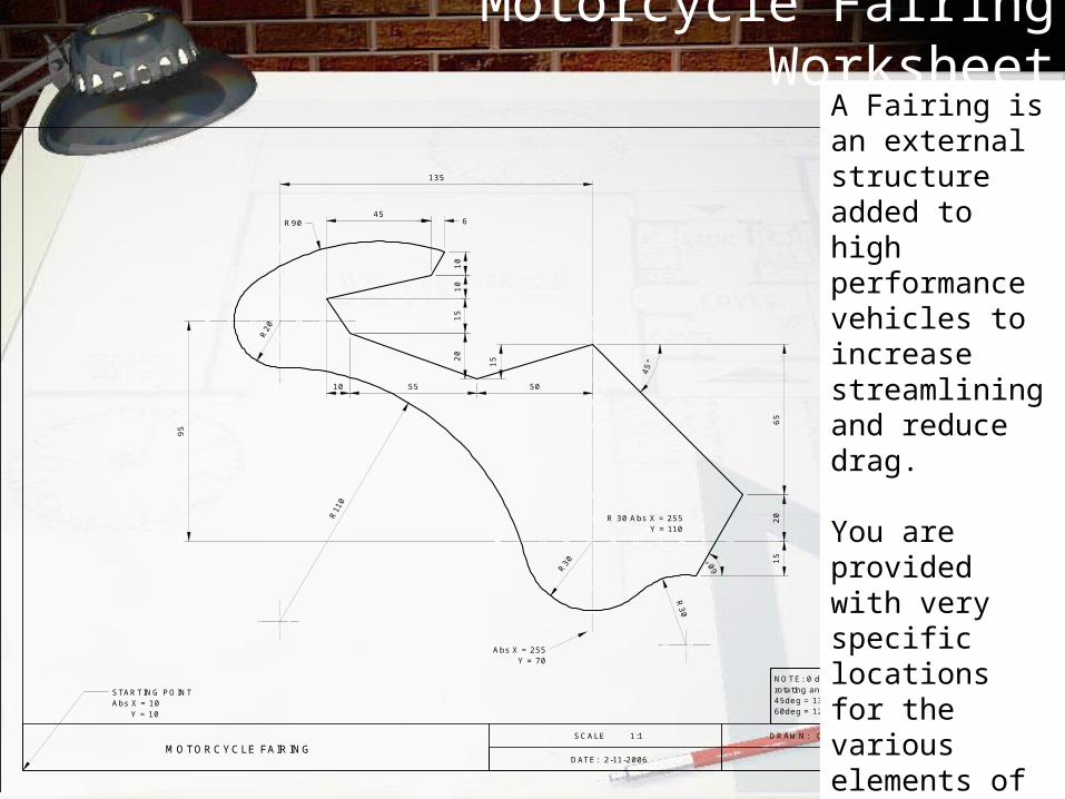
USING 2D DESIGN CAD @ NPBHS WORKSHEETS 4 Motorcycle Fairing Creating tangential arcs & using connected lines. M O TO R C YC LE FAIR IN G SCALE 1:1 DRAWN: C THO M AS D ATE : 2-11-2006 R 30 R 2 0 R 110 R3 0 65 15 60° 45° 50 55 10 R 90 15 20 15 10 10 45 6 Abs X = 255 Y = 70 R 30 A bs X = 255 Y = 110 S TA R TIN G PO IN T Abs X = 10 Y = 10 N O TE :0 deg (360)starts athorizontal ro tating an ti-clockw ise 45deg = 135,225 & 315 (-45)deg 60deg = 120,240 & 300 (-60)deg 20 95 135
-
Upload
jaylene-ledyard -
Category
Documents
-
view
216 -
download
0
Transcript of USING 2D DESIGN CAD @ NPBHS WORKSHEETS 4 Motorcycle Fairing Creating tangential arcs & using...

USING 2D DESIGNCAD @ NPBHS
WORKSHEETS 4Motorcycle FairingCreating tangential
arcs& using connected
lines.
MOTORCYCLE FAIRINGSCALE 1:1 DRAWN: C THOMAS
DATE: 2-11-2006
R30
R20
R11
0
R30
65
15
60°
45°
505510
R90
152
01
51
01
0
456
Abs X = 255Y = 70
R 30 Abs X = 255Y = 110
STARTING POINTAbs X = 10
Y = 10
NOTE: 0 deg (360) starts at horizontalrotating anti -clockwise45deg = 135, 225 & 315 (-45)deg60deg = 120, 240 & 300 (-60)deg
20
95
135
Motorcycle Fairing Worksheet
MOTORCYCLE FAIRINGSCALE 1:1 DRAWN: C THOMAS
DATE: 2-11-2006
R30
R20
R11
0
R30
65
15
60°
45°
505510
R90
15
20
15
101
0
456
Abs X = 255Y = 70
R 30 Abs X = 255Y = 110
STARTING POINTAbs X = 10
Y = 10
NOTE: 0 deg (360) starts at horizontalrotating anti -clockwise45deg = 135, 225 & 315 (-45)deg60deg = 120, 240 & 300 (-60)deg
20
95135
A Fairing is an external structure added to high performance vehicles to increase streamlining and reduce drag.
You are provided with very specific locations for the various elements of this drawing.
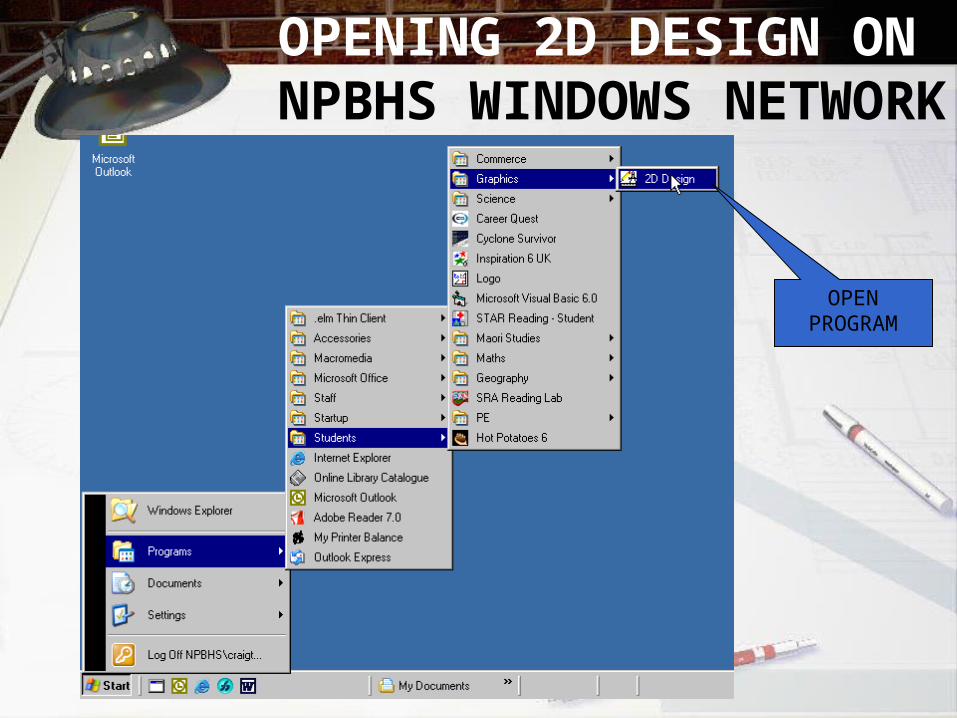
OPENING 2D DESIGN ON NPBHS WINDOWS
NETWORK
OPENPROGRAM
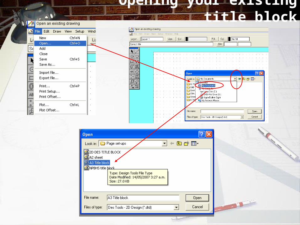
Opening your existing title block
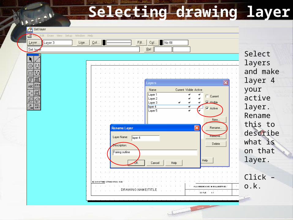
Selecting drawing layer
Select layers and make layer 4 your active layer.Rename this to describe what is on that layer.
Click – o.k.
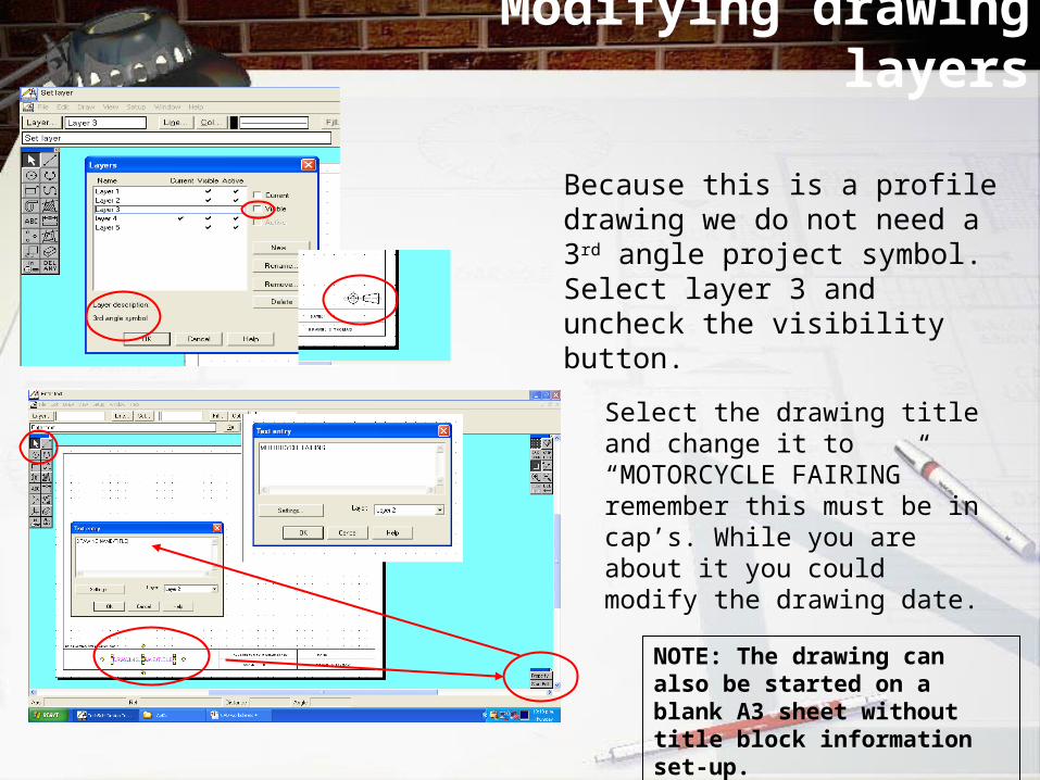
Modifying drawing layers
Because this is a profile drawing we do not need a 3rd angle project symbol. Select layer 3 and uncheck the visibility button.
Select the drawing title and change it to “MOTORCYCLE FAIRING” remember this must be in cap’s. While you are about it you could modify the drawing date.
NOTE: The drawing can also be started on a blank A3 sheet without title block information set-up.

CAD Task - fairing
Create a line starting at the absolute settings X=255,Y=70. Extend the line to be 135mm long at absolute settings X=255,Y=205.
MOTORCYCLE FAIRINGSCALE 1:1 DRAWN: C THOMAS
DATE: 2-11-2006
R30
R20
R11
0
R30
65
15
60°
45°
505510
R90
15
20
15
10
10
456
Abs X = 255Y = 70
R 30 Abs X = 255Y = 110
STARTING POINTAbs X = 10
Y = 10
NOTE: 0 deg (360) starts at horizontalrotating anti -clockwise45deg = 135, 225 & 315 (-45)deg60deg = 120, 240 & 300 (-60)deg
20
95
135
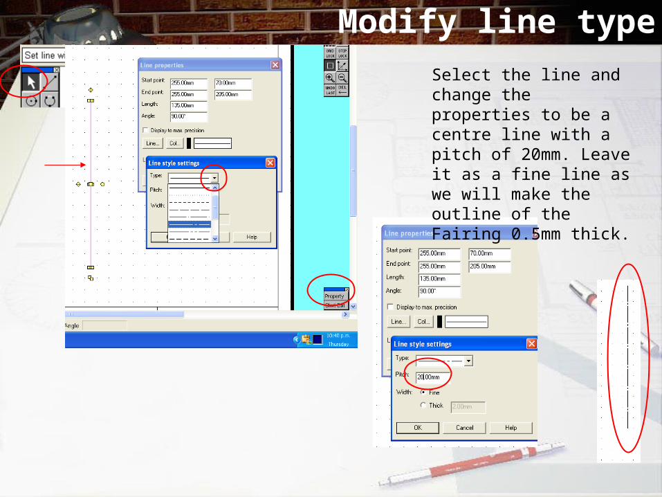
Modify line typeSelect the line and change the properties to be a centre line with a pitch of 20mm. Leave it as a fine line as we will make the outline of the Fairing 0.5mm thick.
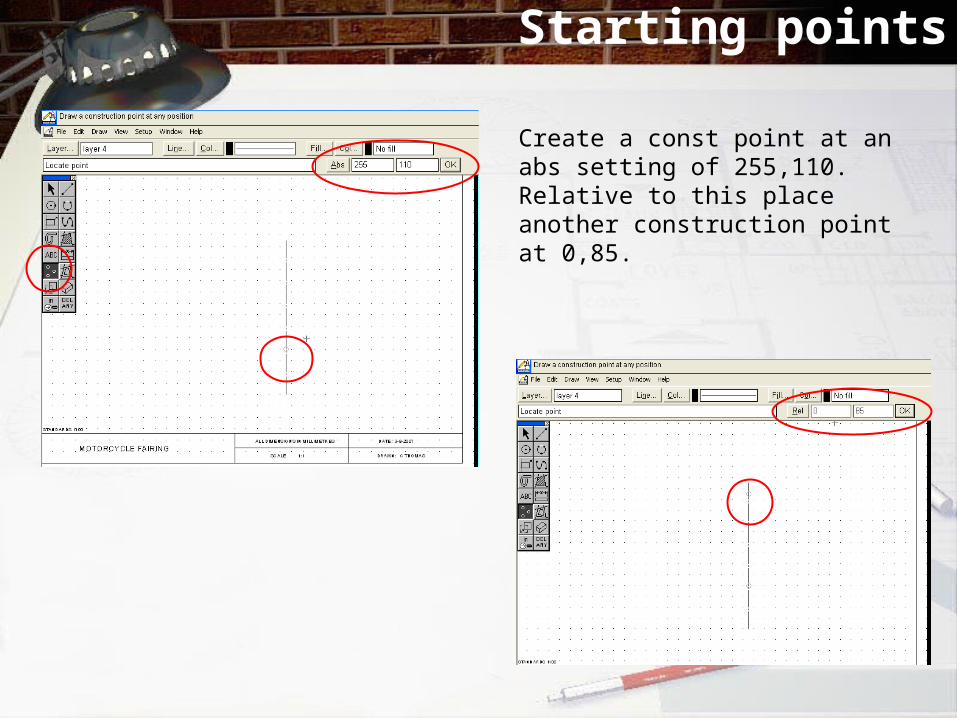
Starting points
Create a const point at an abs setting of 255,110. Relative to this place another construction point at 0,85.
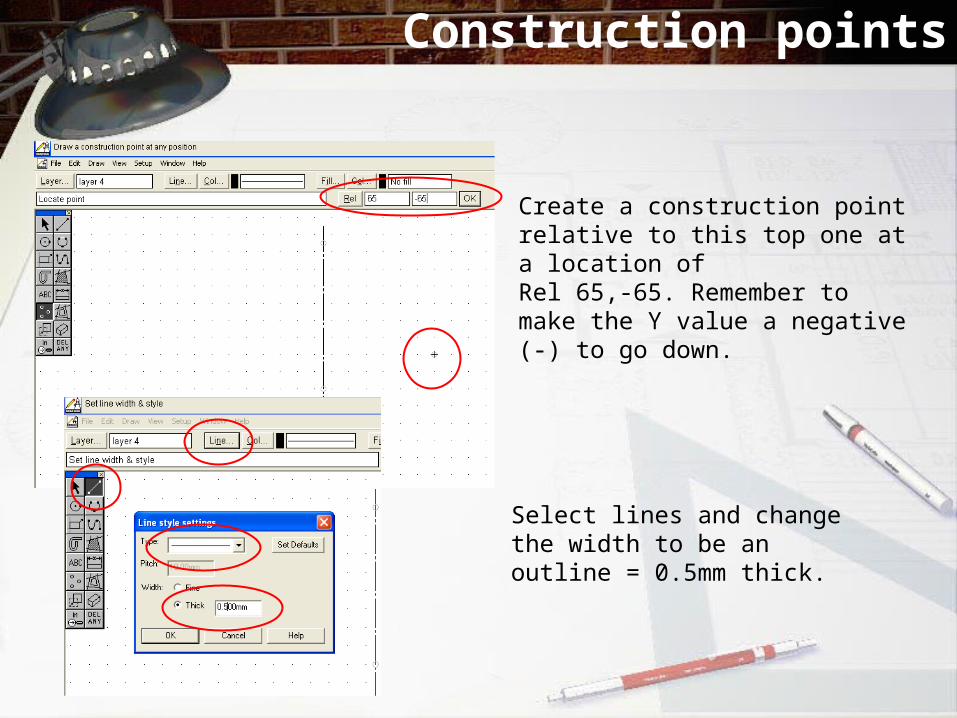
Construction points
Create a construction point relative to this top one at a location of Rel 65,-65. Remember to make the Y value a negative (-) to go down.
Select lines and change the width to be an outline = 0.5mm thick.
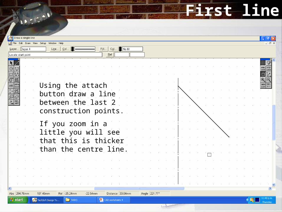
First line
Using the attach button draw a line between the last 2 construction points.
If you zoom in a little you will see that this is thicker than the centre line.
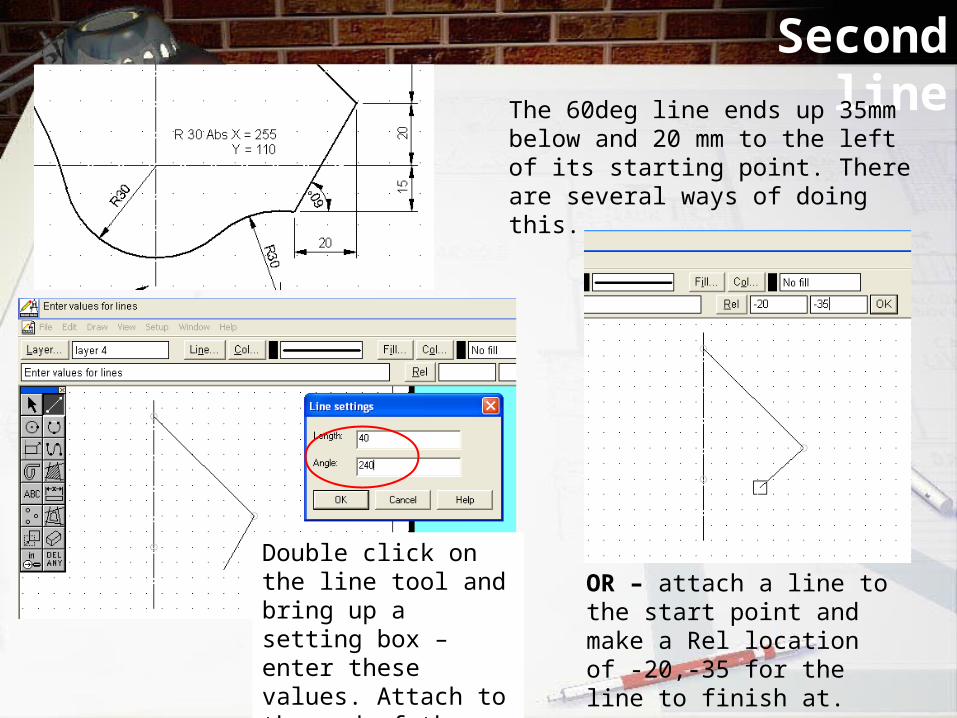
Second lineThe 60deg line ends up 35mm
below and 20 mm to the left of its starting point. There are several ways of doing this.
Double click on the line tool and bring up a setting box – enter these values. Attach to the end of the 45deg line.
OR – attach a line to the start point and make a Rel location of -20,-35 for the line to finish at.
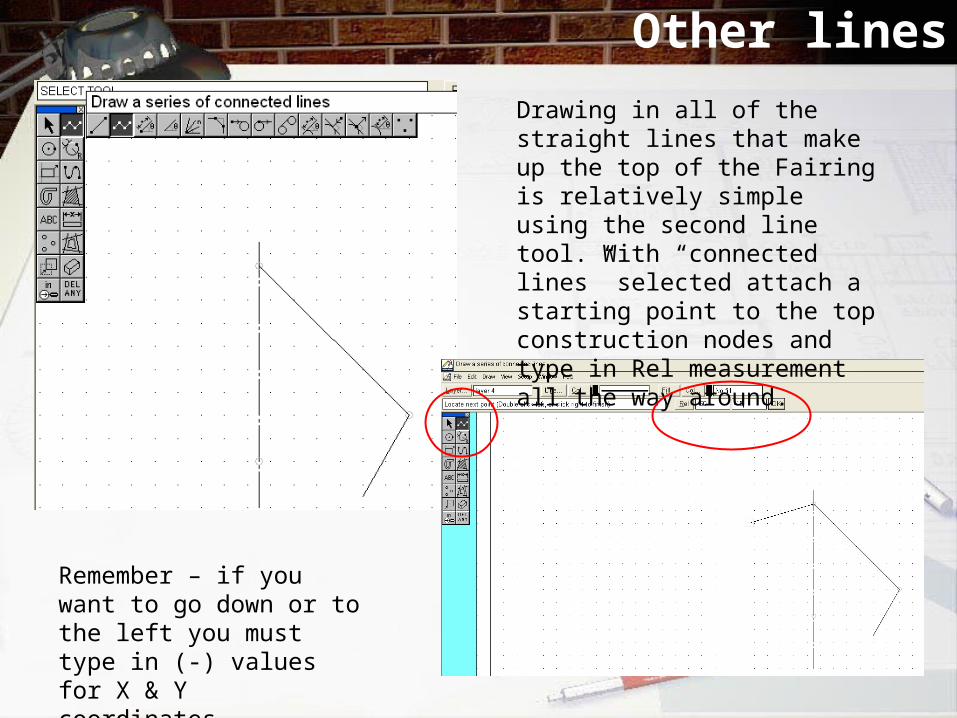
Other lines
Drawing in all of the straight lines that make up the top of the Fairing is relatively simple using the second line tool. With “connected lines” selected attach a starting point to the top construction nodes and type in Rel measurement all the way around.
Remember – if you want to go down or to the left you must type in (-) values for X & Y coordinates.
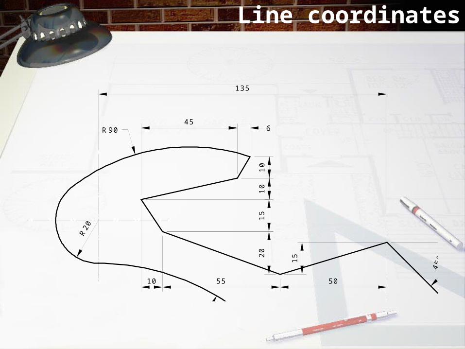
Line coordinates
MOTORCYCLE FAIRINGSCALE 1:1 DRAWN: C THOMAS
DATE: 2-11-2006
R30
R20
R11
0
R30
65
15
60°
45°
505510
R90
15
20
15
101
0
456
Abs X = 255Y = 70
R 30 Abs X = 255Y = 110
STARTING POINTAbs X = 10
Y = 10
NOTE: 0 deg (360) starts at horizontalrotating anti -clockwise45deg = 135, 225 & 315 (-45)deg60deg = 120, 240 & 300 (-60)deg
20
95
135

Finished line work

Circles & Arcs 1
Set a circle with R 30mm and attach it to the bottom construction node.
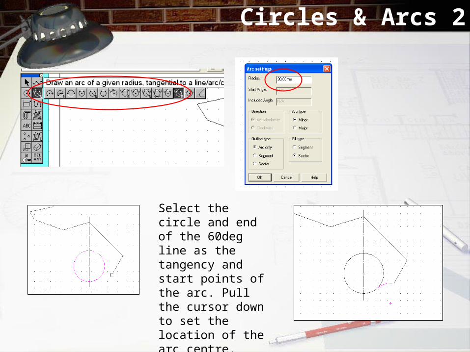
Circles & Arcs 2
Select the circle and end of the 60deg line as the tangency and start points of the arc. Pull the cursor down to set the location of the arc centre.

Circles & Arcs 3
MOTORCYCLE FAIRINGSCALE 1:1 DRAWN: C THOMAS
DATE: 2-11-2006
R30
R20
R11
0
R30
65
15
60°
45°
505510
R90
15
20
15
10
10
456
Abs X = 255Y = 70
R 30 Abs X = 255Y = 110
STARTING POINTAbs X = 10
Y = 10
NOTE: 0 deg (360) starts at horizontalrotating anti -clockwise45deg = 135, 225 & 315 (-45)deg60deg = 120, 240 & 300 (-60)deg
20
95
135
Place a construction node 135 across from and 95 above the centre of your previous circle. This is the centre for the R 20mm circle at the top.

Circles & Arcs 4

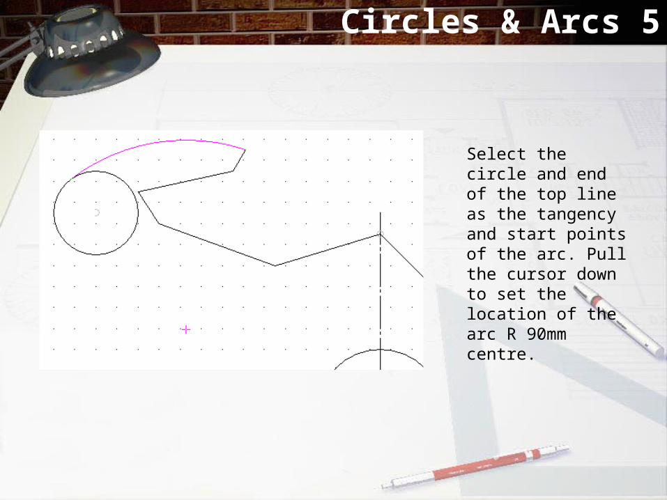
Circles & Arcs 5
Circles & Arcs 5
Select the circle and end of the top line as the tangency and start points of the arc. Pull the cursor down to set the location of the arc R 90mm centre.
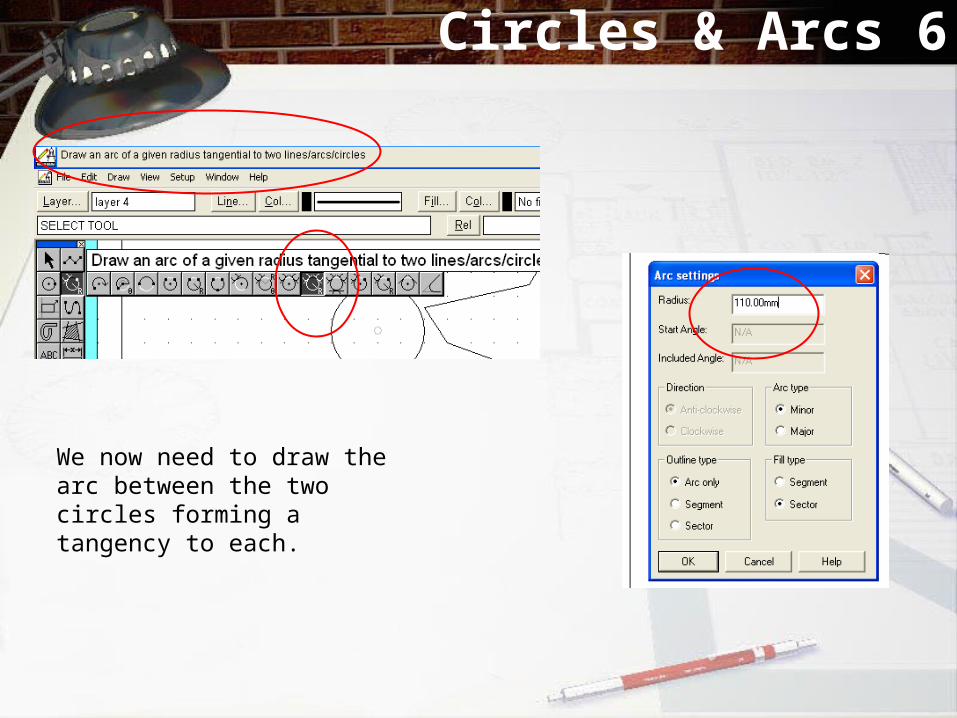
Circles & Arcs 6
We now need to draw the arc between the two circles forming a tangency to each.
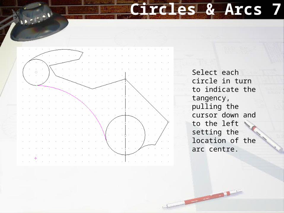
Circles & Arcs 7
Select each circle in turn to indicate the tangency, pulling the cursor down and to the left setting the location of the arc centre.

Tidying up the drawing
Select the correct delete tool so you can remove parts of the circles not required.Click on the redraw button to refresh the view and make the connections again.
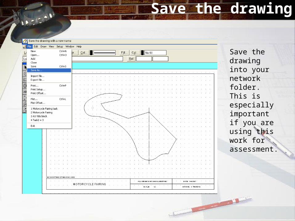
Save the drawing
Save the drawing into your network folder. This is especially important if you are using this work for assessment.

Adding detail – centre lines
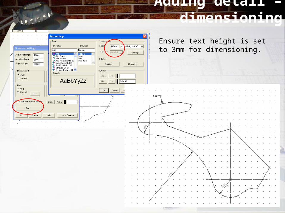
Adding detail – dimensioning
Ensure text height is set to 3mm for dimensioning.

Finished
MOTORCYCLE FAIRINGSCALE 1:1 DRAWN: C THOMAS
DATE: 2-11-2006
R30
R20
R11
0
R30
6515
60°
45°
505510
R90
15
2015
1010
456
Abs X = 255Y = 70
R 30 Abs X = 255Y = 110
STARTING POINTAbs X = 10
Y = 10
NOTE: 0 deg (360) starts at horizontalrotating anti -clockwise45deg = 135, 225 & 315 (-45)deg60deg = 120, 240 & 300 (-60)deg
20
95
135