
Illustrated Guide to Building a Spira International Stitch ...

MMMMEE--111100110033
USER’’S MANUAL
SSuunnSSttaarr CCOO..,, LLTTDD..
TWO-HEAD AUTOMATIC EMBROIDERY MACHINE
FOUR-HEAD AUTOMATIC EMBROIDERY MACHINE
SIX-HEAD AUTOMATIC EMBROIDERY MACHINE
EIGHT-HEAD AUTOMATIC EMBROIDERY MACHINE
SIX-HEAD AUTOMATIC EMBROIDERY MACHINE(Compact Type)
SWF/K-Series


1. THIS IS AN INSTRUCTION FOR SAFE USE OF AUTOMATICEMBROIDERY MACHINES. READ THOROUGHLY BEFORE USE.
2. CONTENTS IN THIS INSTRUCTION MAY CHANGE, WITHOUTPRIOR NOTICE, FOR IMPROVEMENT OF MACHINE QUALITY ANDTHUS MAY NOT CORRESPOND TO THE MACHINE YOUPURCHASED. CONTACT YOUR SALES AGENT FOR INQUIRIES.
3. THIS IS DESIGNED AND MANUFACTURED AS AN INDUSTRIALMACHINE. IT SHOULD NOT BE USED FOR OTHER THANINDUSTRIAL PURPOSE.

i
TABLE OF CONTENTS
CHAPTER 1 SAFETY RULES ................................................................................................................ 1-11-1) DELIVERY OF YOUR MACHINE........................................................................................1-1
1-2) INSTALLATION.....................................................................................................................1-2
1-3) MACHINE OPERATION ...................................................................................................... 1-3
1-4) REPAIR................................................................................................................................... 1-3
1-5) PLACEMENT OF WARNING STICKERS .......................................................................... 1-4
1-6) CONTENTS OF WARNING STICKERS ............................................................................. 1-5
CHAPTER 2 INSTALLATION AND MACHINE ASSEMBLY ............................................................ 2-12-1) ENVIRONMENT ................................................................................................................... 2-1
2-2) ELECTRICITY INSTALLATION ........................................................................................ 2-1
2-3) LEVELING THE MACHINE ................................................................................................ 2-2
2-4) ASSEMBLY OF PERIPHERAL DEVICES ......................................................................... 2-3
2-5) TABLE ASSEMBLY ............................................................................................................. 2-4
2-6) FRAME ASSEMBLY ............................................................................................................ 2-6
2-6-1) TUBULAR FRAME ............................................................................................... 2-6
2-6-2) BORDER FRAME .................................................................................................. 2-7
CHAPTER 3 PARTS OF THE MACHINE .............................................................................................. 3-13-1) SWF/K-U SERIES ................................................................................................................. 3-1
CHAPTER 4 FUNCTIONS AND FEATURES ....................................................................................... 4-1
CHAPTER 5 FUNCTIONS FOR BASIC MACHINE OPERATION ..................................................... 5-15-1) LAMP ON THREAD TENSION ADJUSTMENT BOARD ................................................ 5-1
5-2) NEEDLE STOP CLUTCH...................................................................................................... 5-2
5-3) UPPER THREADING AND TENSION ADJUSTMENT .................................................... 5-3
5-4) LOWER (BOBBIN) THREADING AND TENSION ADJUSTMENT ................................ 5-6
5-5) BOBBIN WINDER ................................................................................................................ 5-7
5-6) PRECAUTIONS IN USING FLOPPY DISKS OR USB MEMORY STICKS .................... 5-9
5-7) INSERTING FLOPPY DISKS AND USB MEMORY STICKS .......................................... 5-9
5-8) DELETING FLOPPY DISKS AND USB MEMORY STICK............................................. 5-10
5-9) READING AND WRITING OF EMBROIDERY DESIGNS ............................................. 5-10
5-10) RETURN TO PREVIOUS LOCATION IN UNEXPECTED BLACKOUTS ................... 5-10
5-11) NEEDLE-HOOK TIMING CONTROL .............................................................................5-11
5-12) ASSEMBLY AND FUNCTIONS OF THREAD DETECTOR ........................................ 5-16
5-12-1) FUNCTIONS OF THREAD DETECTOR ......................................................... 5-16
5-12-2) DISASSEMBLING THREAD DETECTOR ..................................................... 5-16
ii
CHAPTER 6 MAINTENANCE AND INSPECTION ............................................................................. 6-16-1) CHECK POINTS FOR REGULAR INSPECTION .............................................................. 6-1
6-2) CLEANING ........................................................................................................................... 6-1
6-3) OIL SUPPLY ......................................................................................................................... 6-3
6-4) DRIVE BELT TENSION ....................................................................................................... 6-8
CHAPTER 7 MACHINE ADJUSTMENTS ............................................................................................ 7-17-1) ADJUSTING THE TRIMMERS ........................................................................................... 7-1
7-1-1) ADJUSTING THE POSITION OF THE TRIMMING CAM
(INSERT ANGLE OF MOVABLE BLADE) ........................................................ 7-1
7-1-2) ADJUSTING BLADE TENSION .......................................................................... 7-2
7-2) ADJUSTING THE TRIMMER RETURN SPRING ............................................................. 7-2
7-3) ADJUSTING UPPER THREAD HOLDING UNIT ...............................................................7-3
7-4) PICKER ADJUSTMENT ...................................................................................................... 7-4
7-5) ADJUSTING UPPER THREAD HOLDER .......................................................................... 7-5
7-6) ADJUSTING LOW-NOISE PRESSER FOOT ...................................................................... 7-6
7-7) RELATIONSHIP BETWEEN PRESSER FOOT AND NEEDLE ........................................ 7-7
7-8) CORRECT POSITION OF NEEDLE .................................................................................... 7-8
7-9) ADJUSTING HALF-TURN FILM FOR COLOR CHANGE ............................................... 7-9
7-10) JUMP MOTOR ADJUSTMENT ....................................................................................... 7-10
7-11) ADJUSTING DRIVE BELT TENSION ............................................................................ 7-11
7-11-1) Y-AXIS TIMING BELT ..................................................................................... 7-11
7-11-2) X-AXIS TIMING BELT ..................................................................................... 7-12
7-11-3) TIMING BELT ON MAIN SHAFT MOTOR .................................................... 7-12
7-12) LAMP (OPTIONAL) ......................................................................................................... 7-13
7-12-1) LAMP SOCKET ADJUSTMENT (4-HEAD) .................................................... 7-13
7-12-2) DISASSEMBLING CABLE COVER (4-HEAD) .............................................. 7-13
CHAPTER 8 TROUBLESHOOTING ..................................................................................................... 8-1
CHAPTER 9 BLOCK DIAGRAM .......................................................................................................... 9-1

SAFETY RULES
CHAPTER 1
1-1
The following set of safety rules categorized as , , and indicates possibilities ofphysical or property damages if not fully observed.
: These safety instructions MUST be observed to be safe from danger when installing, delivering, orrepairing the machine.
: These safety instructions MUST be observed to be safe from machine injuries.
: These safety instructions MUST be observed to prevent predictable machine errors.CAUTION
WARNING
DANGER
CAUTIONWARNINGDANGER
ONLY TRAINED AND EXPERIENCED PERSONS, FAMILIAR WITH THERELEVANT SAFETY INSTRUCTIONS, SHOULD HANDLE THE MACHINE.MAKE SURE TO FULLY OBSERVE THE FOLLOWING INSTRUCTIONS.
1) Using a craneMake sure that the crane is large enough to hold the machine. Use a nylonrope of sufficient strength. Place a wooden block at either side of themachine before tying the rope. The angle should be 40°Δ or less. Make surethat the rope does not touch the table.
Make sure all personsand obstacles are outof the way of themoving equipment.
[Fig.1-1]
1-1) DELIVERY OFYOUR MACHINE
DANGER
Square strut
Hexagon Bolts
Hexagon Nuts
nylon rope

1-2
2) Using a ForkliftMake sure that size and weight of the forklift is sufficient to support themachine. Use the pallet to place the machine so that its center is on theforklift arm (see [Fig.1-2]). Lift the machine carefully so that the machinedoes not tilt to either side.
[Fig.1-2]
Installation environment may incur machine malfunction or breakdown.Make sure to meet the following conditions.
1) The foundation under the machine, i.e. table or desk, must be strong enoughto support the weight of the machine (approximately 1 ton).
2) Air conditioning can eliminate dust and humidity that can cause pollutionand corrosion of the machine. Make sure your machine is regularly cleaned.
3) Long exposure to direct sunlight can cause the paint of the machine to fadeor change of the machine shape.
4) Allow at least 50cm (20 inches) of space on each side of the machine forconvenient maintenance.
Please refer to for installation details.2. Machine Installation and Assembly
1-2) INSTALLATION
CAUTION
[WARNING]Make sure to maintain the weight balance in machine deliveries,especially when unloading the machine from a forklift or crane, inorder to prevent injury or machine damages.

1-3
Only SWF-trained and selected repair engineers should do repair work.
1) Turn OFF the power before cleaning or repairing the machine. Wait for 4minutes so the machine electricity is completely discharged.
2) Do not change the settings or any parts on the machine withoutconfirmation from SWF. Such change may cause safety accidents.
3) Use only SWF parts when repairing your machine.4) Replace all safety covers when you are finished with your repair.
1-4) REPAIR
DANGER
The SWF Automatic Embroidery Machine is designed for applyingembroidery to fabric and other similar materials.
Pay careful attention to the and stickers on certainparts of the machine. Make sure to observe the following when operatingthe machine:
01) Read thoroughly and fully understand the manual before operating themachine.
02) Dress for safety. Long and unbound hair, jewelry such as necklaces,bracelets, and wide sleeves can get caught in the machine. Wear shoeswith non-slip soles.
03) Clear all persons from the machine before turning on the power. 04) Keep your hands or head away from the moving parts of the machine such
as needle, hook, take-up lever, and pulley when the machine is inoperation.
05) Do not remove the safety cover on the pulley or shaft when the machine isin operation.
06) Be sure the main power is turned off and the power switch is set to OFFbefore opening the cover of any electrical component or control box.
07) Be sure the main switch is OFF before manually turning the main shaft.08) Turn the machine off when threading needles or inspecting the finished
embroidery.09) Do not lean against the cradle or place your fingers near the guide grooves
of the frame.10) The machine noise may exceed 85db when it is run at a maximum speed.
It is not higher than the standard level, but you may need earplugs orsound-proof facilities for the operator and other workers.
CAUTIONWARNING
1-3) MACHINEOPERATION
[CAUTION]It takes about 10 minutes after turning off the main switch before theelectricity is fully discharged from X/Y main shafts and the drive box.
WARNING

1-4
Observe the directions on ALL warning stickers placed on the machine asreminders for your safety.
1) Location of Warning Stickers
1-5) Placement ofWarning Stickers
Fire or death may be caused byhigh voltage electric shock.Don’t open the cover except forservice man assigned by SWF.When open the cover turn offpower and wait for 6 minutes.
Open the upper shaft cover ofeach head and supply thedesignated oil.
Injury may be caused by winding.
Be sure to turn off the powerbefore cleaning, lubricating,adjusting or repairing.
Physical damage may becaused by winding.
Don’t put your hands near thearrow while the main shaft isrotating
Injury may be caused by movingneedle.
Ensure that the machine is in astop condition before changing,threading or rethreading ofneedies or changing of needles.
Turn off the main power beforerotating the main shaft by hand!
Do not remove covers duringoperation!
Turn off the main power beforeopening electricity-related boxes!
Physical damage may be causedby interposition.While embroidery frame is runningaccording to the direction ofembroidery frame may be injuredyour hands by gap between fixedbody and embroidery frame.
Physical injury may be causedby crevice.
Don t put your finger in a grooveon the table.
[Fig.1-3 Front]
[Fig.1-4 From top]

1-5
1) Warning1-6) Contents ofWarning Stickers
Injury may be caused by movingneedle.
Ensure that the machine is in a stopcondition before changing, threading orrethreading of needies or changing ofneedles.
Fire or death may be caused by highvoltage electric shock.
Don’t open the cover except for serviceman assigned by SWF.
When open the cover turn off power andwait for 6 minutes.
[ Notice ] Safety cover in the WARNING refers to all covers
near the operating parts of the machine.
Injury may be caused by winding.
Be sure to turn off the power beforecleaning, lubricating, adjusting orrepairing.

2-1
Install your machine in an appropriate environment and with adequate electrical supply. Failure to follow thedirections may result in machine malfunction.
2-1) ENVIRONMENT
1) Temperature: ① 0∼40°C (32∼104°F) when the machine is in operation②-25∼55°C (-13∼131°F) when the machine is not in operation
2) Humidity: 45∼90% (relative)
3) Grounding: Ensure the electricity is properly grounded.
4) Close any doors and windows near the machine to prevent direct light, dust, and humidity.5) Foundation under the machine must be a sufficiently strong and flat concrete to support the weight of the
machine.
2-2) ELECTRICITY INSTALLATION
Check if the input voltage of the machine is in the right range of the voltage supply before installing or operatingthe machine. The voltage required is as follows:
1) Input voltage (to be adjusted when installing): 110V, 220V2) Allowed range of voltage: within ±10% of the voltage set3) Electric capacity and voltage consumption: 640VA 440W4) Insulation resistance: over 10M ohms (measured with 500V insulation tester)
INSTALLATION AND MACHINE ASSEMBLY
CHAPTER 2
[CAUTION]Do not let moisture drops on the machine.Provide air conditioning to control humidity and to prevent dust and corrosion.
DANGER
WARNING
Properly ground the machine to avoid the possibility of electric shock. Use three-wiregrounding (grounding resistance below 100 ohms).
Check the voltage supply where the machine will be installed.Install the cable away from the operator’s work space to prevent accident or injury.

2-2
2-3) LEVELING THE MACHINE
The machine must be accurately leveled (especially front and back) to prevent the needle from moving out ofposition.
1) Use the adjusting bolts installed at the four stands to level the machine (front, rear, left, and right). Use a levelgauge.① Check the voltage supply where the machine will be installed.② Install the cable away from the operator’s work space to prevent accident or injury.③ If the difference in heights of the four bolts is over 10mm, place spacers beneath the lower adjusting bolts to
make the heights even.
2) The machine must be horizontally balanced on all four sides - front, rear, right, and left.
3) Using the level gaugeUse a nut to fully fasten the adjusting bolts when the machine is leveled.
[CAUTION]The level gauge does not measure accurately on a square pipe or a table.
[Fig.2-2]
[Fig.2-3]
[Fig.2-1]
Level gauge
Level gauge
Adjusting bolts
Level base

2-3
2-4) ASSEMBLY OF PERIPHERAL DEVICES
1) Assembling Upper Thread Stand
2) Assembling Operation Box
[Fig.2-4]
[Fig.2-5] [Fig.2-6]
Spool plate
thread holder
Operation box
support

2-4
2-5) TABLE ASSEMBLY
1) Unscrew the eight clamps underneath the table and the bolts to disassemble the table.
2) Adjust the table support at an appropriate height and fasten the bolts.
[Fig.2-7]
[Fig.2-8]
Clamp
Clamp
Clamp
Table support
Table
Table supportbolts
Bolts
Table height
Work type board tubular cap

2-5
3) Insert the table and fasten the bolts and the clamps.
[Fig.2-9]
[Fig.2-10]
[CAUTION]The table should not be higher than the upper side of the needle plate by 0.5mm for board framework. If the height difference is over 0.5mm, unfasten the table support bolts, adjust the height, andfasten the bolts back.
Clamp
Clamp
Clamp
Table support
Bolts
height difference
if gap is largerthan 0.5mm
Table support
Bolts

2-6
2-6) FRAME ASSEMBLY
2-6-1) Tubular Frame
1) Unfasten screws on the tubular frame 2/3, install the tubular frame in the groove of the frame connection plate,and fasten the bolt.
2) Insert the frame into the tubular frame. Use the screws to adjust the space.
[Fig.2-11]
Tubular frame
Frame connection plate
Fixing hole
Fixing bolt
[CAUTION] Do not install the tubular frame too close from the X frame. Keep the space at around 2mm.

2-7
[Fig.2-12]
[Fig.2-13]
Tubular frame
Fixing bolts
Screws
Fixing bolts
2-6-2) Border Frame
1) Unfasten screws on the tubular frame 2/3 and remove the frame.
2) Adjust the table height at an appropriate level for border frame work. (See 2.5) TABLE ASSEMBLY)
3) Unfasten screws on the border frame 2/3 and install the border frame in the groove of the X frame connectionplate. Fasten the bolt.
[CAUTION]At this time, don't keep a border frame close to the X-frame by force and tighten the bolt whilemaintaining the gap of about 2mm between the two frames.

PARTS OF THE MACHINE
CHAPTER 3
3-1
[Fig.3-1]
Machine BodyTableUpper thread standMain shaft drive motorRotary hook baseTrimming cam boxArm
Color ChangeUpper thread holderHeadThread tensionadjustment boardSub-controllerX-axis driving system
Y-axis driving systemEmergency stopS/B buttonTubular frameBorder frameController boxOperation box
EncoderMain power switchLeveling baseThread detectorEmergency powerTransformer box
3-1) SWF/E-U SERIES

4-1
01) EXPANDED MEMORY SIZEThe machine can store a maximum of 100 designs. The basic memory size is 2 million stitches.
02) MIRROR IMAGE CONVERSION AND DESIGN DIRECTIONYou can turn the design from 0°to 359°in the increments of 1°and also reverse the design in the X direction(mirror image).
03) ENLARGING AND REDUCING DESIGNYou can reduce or enlarge the embroidery design in size from 50% to 200% by 1% along the X and Y axis.
04) AUTOMATIC SELECTION OF NEEDLE BARYou can select the order of the needle bars up to the 300th bar.
05) GENERAL REPETITION WORKThe same design can be repeated up to 99 times along the X and Y axis.
06) AUTOMATIC OFFSETThe frame automatically returns to the offset point when the embroidery is finished to make it easier for you toswitch the frames. You can select AUTOMATIC OFFSET at PARAMETER SELECT MODE to move the frameautomatically to the desired point, making it easier to do appliques and to switch the frames.
07) MANUAL OFFSETYou can manually move the frame to the pre-selected point to do appliques or change the frames during embroiderywork. The frame can be moved back to its original place by simply pressing the right buttons.
08) RETURN TO STARTThe frame can be moved back to the start point of the design during the embroidery work.
09) NON-STITCHINGThe frame and the needle bar can move back and forth by the units of 1, 100, 1000, and 10000 stitches and by colorwithout stitching.
10) FRAME REVERSALWhen the thread breaks or runs out of track, you can move the needle bar back to the starting point of the design inthe units of one to ten stitches.
11) AUTOMATIC TRIMMINGThe automatic trimming function, determined by the design and the machine set-up, enhances work productivity andquality of the finished product.
FUNCTIONS AND FEATURES
CHAPTER 4
4-2
12) AUTOMATIC DETECTION OF UPPER AND LOWER THREAD BREAKS① Spring Type① The upper and the lower threads are detected by two separate devices. The machine stops automatically when the
upper thread breaks or the lower thread is out of the needle (lower thread detector is optional for all machinesexcept for single-head).
② Wheel Type② Wheel and wheel sensor board are installed in the tension adjustment board to detect both the upper and the lower
threads. The machine stops automatically when the upper thread breaks or the lower thread is out of the needle.
13) AUTOMATIC RETURN TO STOP POINT IN UNEXPECTED BLACKOUTWhen the power fails unexpectedly, the frame moves back to the exact point where the stitching stopped. This helpsreduce the number of defects.
14) 3.5”FLOPPY DRIVE (EMBEDDED)A 3.5”floppy drive is embedded in the operation panel for you to read or store designs. Both 2DD and 2HD diskscan be used.
15) EDITINGYou can delete, change, or insert stitch data and function codes (jump, finish, trimming).
16) AUTOMATIC STORAGE OF DESIGN SET-UPThe machine automatically stores “basic set-up”for each design and calls the set-ups when a specific design iscalled. This reduces your preparation time.
17) INDIVIDUAL HEAD OPERATIONYou can work on the specific head with a broken thread.
18) MACHINE STOPPAGEThe screen will indicate why the machine has stopped.
19) RPMThe screen indicates rpm.
20) FRAME SPEED SET-UPYou can adjust the frame speed to high, medium, or low.
21) UNUSED MEMORY The screen indicates the memory available for use.
22) TAPE CODE COMPATIBILITY2-binary and 3-binary tape codes can be edited.
23) CODES FROM OTHER BRANDSThe machine can automatically read designs of various formats stored in the floppy disk. These formats includeSST/ DST, DSB, DSZ/ TAP/ FMC, FDR/ ZSK/ 10O/ EXP.

5-1
FUNCTIONS FOR BASIC MACHINE OPERATION
CHAPTER 5
5-1) LAMP ON THREAD TENSION ADJUSTMENT BOARD
1) Switch
① For normal operation, turn the toggle switch on to turn on the indicator lamp. ② If the machine stopped after detecting a thread break, move the frame back to the location of the thread break
using STOP button and restart the machine to pick up stitching (design edit).
③ To set the needle bar so a specific head does not work, turn the toggle switch off.
2) Thread Break Detector Lamp
Lamp on a specific head will blink when thread break is detected at the head, while lamps on other heads will beturned off. You cannot turn the lamp on or off on the other heads using the toggle switch.
[Fig.5-1]
[CAUTION 2]Foreign substances around the thread detector roller may block smooth rotation of the roller andcause wrong detection of thread break.
[CAUTION 1]The take-up lever continues to operate even when the head is turned off. This movement can causethe upper thread to come out of the holder. Use a rubber magnet to fix the unused upper thread.
[NOTE] If you want to move the frame back for any reason when a thread break has NOT occurred, pressthe toggle twice (OFF and ON again).
ON
Thread detectiondelete
Lamp Toggle switchON
Thread sensor roller
OFF
OFF

5-2
3) Deletion of Thread-Break Detection Function
Poor function of the thread detecting roller due to foreign substances around it may result in wrong and frequentdetections, causing inefficiency of work. In this case, you can turn off the detecting function by turning off thetoggle switch at the end of the thread tension adjustment board. This will turn off the detecting function on thehead you are working with.
5-2) NEEDLE STOP CLUTCH
As illustrated in [Fig.5-2], the needle bar will not move when you pull the jump clutch lever. Push the level to theopposite direction of the operator to do move needle bar up and down.
Jump manual clutch lever
[Fig.5-2]
CAUTION
The trimmer and the take-up lever continue to move even when the needle bar isstopped by the clutch. Avoid any operations, i.e. threading the needle or changingthread.Long-time operation of the needle bar with the clutch may damage the bar controller.
5-3
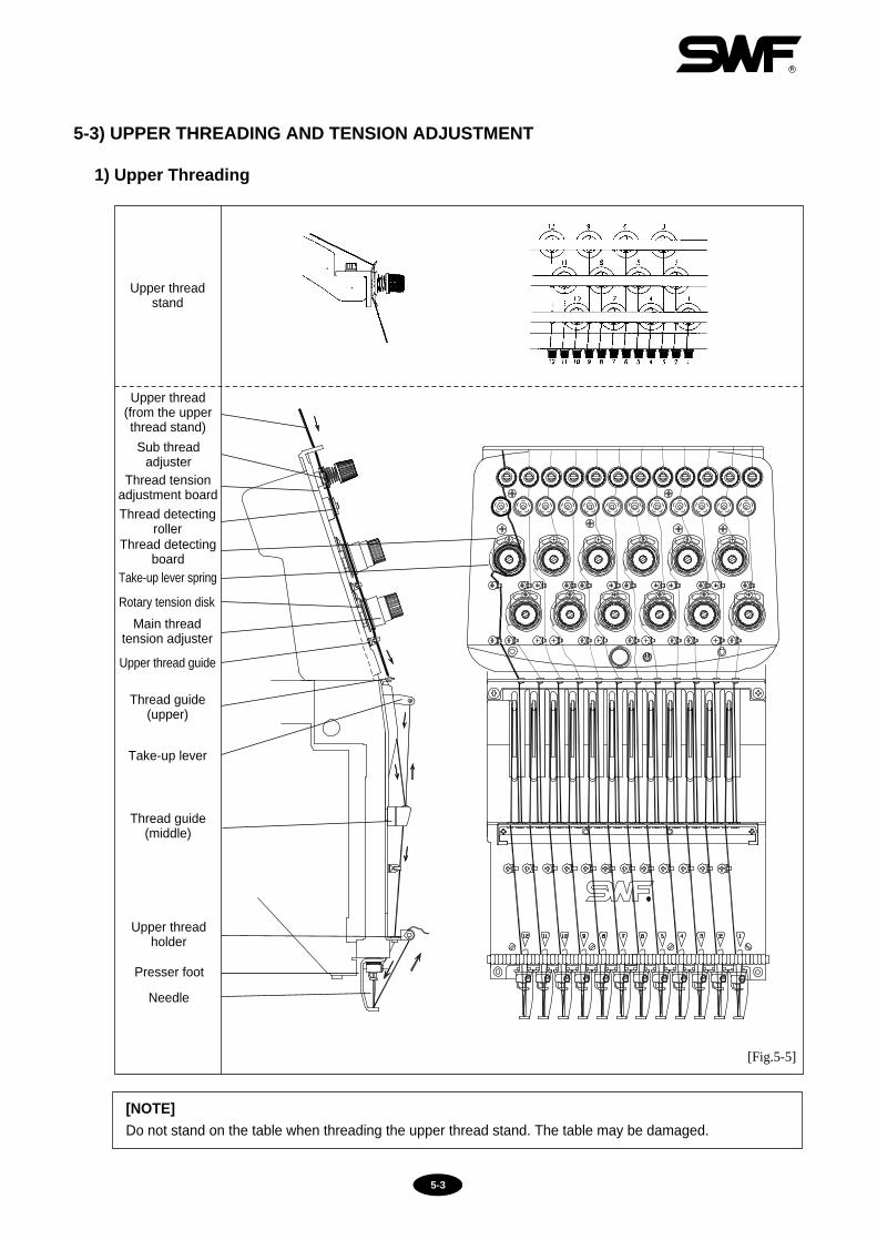
5-3) UPPER THREADING AND TENSION ADJUSTMENT
1) Upper Threading
[NOTE]Do not stand on the table when threading the upper thread stand. The table may be damaged.
Upper threadstand
Upper thread(from the upperthread stand)
Sub threadadjuster
Thread tensionadjustment board
Thread detectingroller
Thread detectingboard
Rotary tension disk
Main threadtension adjuster
Upper thread guide
Thread guide(upper)
Take-up lever
Thread guide(middle)
Presser foot
Needle
[Fig.5-5]
Take-up lever spring
Upper threadholder

5-4
Adjusting nut
Sub-tensionadjuster
Maintensionadjuster
2) Upper Thread Tension Adjustment
① The upper thread tension is controlled by thesub and main thread tension adjusters. Turnclockwise to increase the tension and counter-clockwise to decrease the tension.
② The sub-tension adjusters should control about2/3 of the thread tension while the main adjustershould handle the other 1/3. Set the sub-tensionadjuster so the upper thread flows smoothlythrough the rotary tension disks and into therollers of the main tension adjuster.
[CAUTION]If tension at the sub adjuster is too loose,the detector roller may not rotate well andmake wrong detections.After adjusting the tension, check if theupper thread tension is what can be pulledwith little force of around 100-120g.
[CAUTION]After adjusting the tension, pull the upperthread to see if the detector roller rotateswell.Adjust the tension according to the type ofthread and fabric used.
Thread tension adjustment is critical for producing high quality of the embroidery. A balance of 2/3 upperthread and 1/3 lower thread generally indicates good tension. If the tension is too loose, the upper threadwill loop, causing thread tangles or breaks. If the tension is too tight, puckering may occur as well asthread and needle breaks.
[Fig.5-6]
[Fig.5-7]
Thread Guide Disk(Pass through the
middle of shaft)Rotary Tension Disk
Thread holderspring
Thread guide(lower)
Threading the subtension adjuster
Threading the maintension adjuster
Threading the threaddetector roller
Threading around theneedle
Wrap the thread 1.5 timesaround the rotary tensiondisk (V-shaped groove.)
Wrap the threadclockwise around thethread guide disk.
Wrap the thread aroundthe detector roller onetime.
Fix the upper threadbetween the threadholder spring of the lowerthread guide.
Thread SensingRoller
One turnOne andhalf turn

5-5
3) Take-Up Spring
[CAUTION 2]After adjusting the operating capacity of thetake-up spring, check if the spring connectswith the stopper.
① Take-up Spring FunctionsDifference in the length of the upper thread pulled by the take-up lever and pulled by the hook creates tensionor looping. When the tension is too weak, the take-up spring handles the leftover length of the upper thread.Increase the tension or the stroke of the spring to form tight stitches on the embroidery.
② Take-up Spring Adjustment ⓐ If the spring tension is too weak:
Turn the tension adjusting stud clockwise toincrease the tension.
ⓑ If the spring tension is too tight: Turn the tension adjusting stud counter-clockwise todecrease the tension.
③ Adjusting stroke of the take-up spring:To adjust the stroke of the spring during embroiderywork, move the take-up spring stopper to right orleft as shown in [Fig.5-9].
Stopper
Threadtensionadjustingstud
CORRECT WRONG
Take-up spring
[Fig.5-9]
[Fig.5-8]
Take-up spring unable to connect with the stopper (due to dust or foreign substances in the stopper.)
Connect between the take-up spring and the stopper.
[CAUTION 1]Keep the area clean for connection betweenthe spring and the stopper.

5-6
[Fig.5-10]
[Fig.5-11]
5-4) LOWER (BOBBIN) THREADING ANDTENSION ADJUSTMENT
1) Lower Threading
① Use cotton yarn (#80-#120) for your lower thread.② Threading the bobbin:
ⓐ Insert the threaded bobbin into the bobbin case withthe thread coming out from the case slot. Pull thethread through the thread guide. Check if the bobbinis rotating ([Fig.5-10]).
ⓑ Thread the lower thread holder and trim the threadto 3-4cm before inserting the bobbin and the caseinto the hook assembly. Long tail can cause thethread to tangle during stitching.
2) Lower Thread Tension Adjustment
Adjust the tension of the lower thread using the nut on thetension spring on the bobbin case. Turn the nut clockwiseto increase the tension and counterclockwise to decreasethe tension.
[CAUTION 1]Direction of the Bobbin Rotation Make sure that the bobbin rotates clockwisewhen you pull the thread holding the bobbin casein your left hand([Fig 5-10]).
[CAUTION 2]For adequate bobbin thread tension, hold a threadfrom the bobbin and jiggle the bobbin case lightly upand down([Fig 5-11]). The case should drop and thetension should be 25-35g.
Lower threadholder
Bobbin
Slot
3~4 cm
Screw
Tension spring
Bobbin case
Driver
Thread guide

5-7
5-5) THREAD WINDER
1) Lower thread winding
① Insert the bobbin into the thread winder shaft as in [Fig. 5-12]. Wind the bobbin 5-6 times by hand in thethread winding direction. Then press the start button, and the thread winding begins.
② If the thread winding status is poor, press the stop button. Then the winding stops immediately.
2) Adjustment of bobbin thread volume
① When winding thread around the bobbin, the thread volume should be some 80% of the bobbin size in terms of
diameter as in [Fig. 5-13].
② Bobbin thread volume is adjusted by the thread
winder knob. When the knob is turned clockwise,
the bobbin thread gets thicker. When the knob is
turned counter-clockwise, the bobbin thread gets
thinner.
[Fig.5-12]
minTIMERSTARTSTOP
max
Knob
Tension adjusting holderTightening screw for the tension adjusting holder
Bobbin axis
Bobbin
Thread tension adjusting nut
[Fig.5-13]
[Fig.5-14]
80%
Decrease
Increase
Knob
[CAUTION]1. If the bobbin thread volume is too high, the
lower thread is not properly released.2. When the lower thread is wound by 80% of
the standard bobbin size, it means some 80m.

5-8
[Fig.5-16]
[CAUTION 1]Winding the bobbin off-center or uneven as shown below can cause thread breaks, skipped stitches,or thread tangles.
[CAUTION 2]Too tight tension of the bobbin thread may block smooth pulling of the thread and cause thread breaks orshort tails.
3) Adjustment of bobbin thread status
① The thread should be wound around the bobbin in
parallel. Otherwise, loosen the tightening screw
for the thread winder's tension adjusting holder
and move the thread guide body left or right for
adjustment.
② The tightening level of the bobbin thread can be
adjusted with the tension adjusting nut.
[Fig.5-15]
Thread tensionadjusting nut
Tension adjusting holder
Tightening screw for the tensionadjusting holder

5-9
5-6) Precautions in using floppy disks or USB memory sticks
Make sure to meet the following conditions when using the above devices.
▶ When using floppy disks– Keep the disks away from objects with magnetic fields, i.e. televisions, radios.– Protect the disks from excess heat, humidity, and direct sunlight.– Do not place heavy objects on the disks.– Do not remove the disk from the drive while formatting, reading, or writing the disk.– Do not open the cover of the disk drive.– Data cannot be written onto the write-protected disks.– Repetitious reading and writing on a single disk may cause errors.– Save your important data on more than one disk for back up.
▶ When using USB memory sticks– Do not delete USB memory from the USB port when reading and writing with USB.
CAUTION
1) You can use pre-formatted disks, but be sure to use disks of recognized quality.2) You can use USB memory sticks of FAT 16 (file system). The machine does not
accommodate FAT 32.
5-7) Inserting floppy disks and USB memorysticks
– Inserting floppy disksInsert the disk in the indicated direction.
– Inserting USB memory sticksInsert the USB memory into the USB port.
[Fig.5-17]
Floppy disk
USB memory
5-10
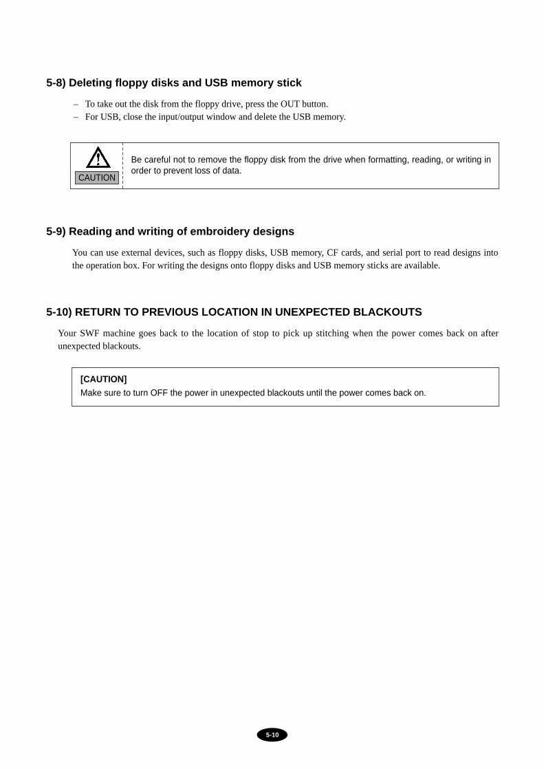
5-8) Deleting floppy disks and USB memory stick
– To take out the disk from the floppy drive, press the OUT button.– For USB, close the input/output window and delete the USB memory.
5-9) Reading and writing of embroidery designs
You can use external devices, such as floppy disks, USB memory, CF cards, and serial port to read designs intothe operation box. For writing the designs onto floppy disks and USB memory sticks are available.
CAUTION
Be careful not to remove the floppy disk from the drive when formatting, reading, or writing inorder to prevent loss of data.
5-10) RETURN TO PREVIOUS LOCATION IN UNEXPECTED BLACKOUTS
Your SWF machine goes back to the location of stop to pick up stitching when the power comes back on afterunexpected blackouts.
[CAUTION]Make sure to turn OFF the power in unexpected blackouts until the power comes back on.

5-11
5-11) NEEDLE-HOOK TIMING CONTROL
1) Needle
① It is very important to select the right needle for the type of thread and fabric used.② Inappropriate needle may cause bad embroidery, thread breaks, skipped stitches, etc.③ For normal embroidery, use a DB×K5 needle.
2) Relationship between Needle and Thread
① Inadequate selection of thread and needle may result in thread breaks, skipped stitches, as well as in bad-quality embroidery.
② Refer to the following table of threads and needles used for normal embroidery.
3) Changing the Needle
① Make sure the needle is completely clear of the needle plate before attempting to change it. If the needle is notclear of the plate, manually turn the main shaft with a hand lever to put the needle in the right location forchange.
[CAUTION]Needle and thread most commonly used in embroidery are DB K5 #11 and rayon yarn 120d/2.
[Fig.5-18]
NEEDLE SIZE THREAD SIZE
US
0.25
0.27
0.29
0.32
0.34
0.36
Japan
9
10
11
12
13
14
Germany Cotton Silk
100~120
80~100
60~70
Nylon
130~150
100~130
80~100
Rayon
70~100
100~130
70~80
Needle
Needle plate
50~60
50~60
65
70
75
80
85
90130~150
CAUTION
[CAUTION]DB K5 needle has an eye twice larger than that of DB1 (used for normal sewing). Use DB X K5 fornormal embroidery.
STOP the machine beforeturning the shaft manually.Immediately remove the leverafterward: it is dangerous tooperate the machine with thelever inserted.
Main shaftlever

5-12
② When inserting the needle, make sure that the grooveof the needle is facing front. Shaft of the needle shouldbe inserted completely into the needle bar.
[CAUTION 1]For special threads such as artificial silk, turn theneedle slightly to the right to prevent thread breaks(see [Fig.5-20]).
[CAUTION 2]If the needle is not inserted all the way to the top of the needle bar hole, timing of the machine will gooff, causing broken needles and thread breaks.
[Fig.5-19]
[Fig.5-20]
Needle insert hole
Front groove of theneedle groove

5-13
4) Relationship between Needle and Hook
① Adjusting Timing between Needle and HookDefault timing of the needle and the hook is set by the main shaft angle of 200° and varies as below.
② Adjusting Gap between Needle and Hook Point
• Gap between the hook point and the scarf of the needleshould be 0.1∼0.3 mm minimum.
• Thread skip occurs due to thread looping or inadequatebalance/gap between the needle and the hook. The closerthe hook point is to the needle, the hook point will beinside the loop and threading will be more stable.
[Fig.5-21]
[Fig.5-23]
Hook point
0.1~0.3mm
[Fig.5-22]
Top point of hookcircumference
Top edge ofneedle eye
Needle tip
Top edge of the needle eye
Hook allowance(gap)
Hook point
Lower dead stopof the needle
Hook point
a. At lower dead stop of the needle bar 2.3 3.7 mm
1.8 2.2 mm
0.5 1.5 mm
The figures may change accordingto needle specification/number.
b. At needle-hook timing
c. At needle-hook timing
[CAUTION]The hook can move right and left if there is an allowance inthe lower shaft gear. Eliminate the allowance (gap) byturning the hook clockwise. Then adjust the timing.

5-14
[Fig.5-24]
[Fig.5-25]
Back groove
Needle eye
Front groove
[CAUTION] Functions by Needle Shape
① Size of the hole and groove differs by needle.• Front groove: protects the thread from the heat of the
sewing friction (which may cause thread breaks).• Back groove: helps regulate the hook timing and
prevents looping.
Prevention of looping is important for stitching. Adjust the hook point as close to the needle as possible to achievethe perfect thread position.
② If thread breaks or stitches are unstable, turn the needle slightlyto the right.
[NOTE]Shape of the loop varies by the type of thread or fabric. Unstable shape of the loop may result in skippedstitches. The following pictures show different shapes of loop formed by different types of thread.
Hook point
Cotton thread loop
Synthetic thread loop
Hook point
[Fig.5-26]

5-15
5) Relationship between the Take-up Lever and the Hook
Hook point timing is directly related to thread tension and thread breaks. The following pictures show the locationof hook when the take-up lever starts to move up from the lower dead stop (main shaft rotation angle: 292°).
[CAUTION] In normal hook timing, the hook should be in the (C) range in the picture below.
FAST HOOK TIMING
SLOW HOOK TIMING
[Fig.5-27]
too small
too large
[Fig.5-28]
[Fig.5-29]
(B)
(C)(A)
Groove of the hook is in the (A) range. Thehook point will take up the thread when the loopis too small. Stitching will be faster than thetake-up movement. As a result, the threadtension will be too loose, upper thread loop willbe too small, and skipped stitches will occur.
Groove of the hook is in the (B) range. The hookpoint will take up the thread when the loop is toolarge, so there may not be skipped stitches.However, the take-up movement will be fasterthan the stitching and thread breaks may occur.

5-16
5-12) ASSEMBLY AND FUNCTIONS OF THREAD DETECTOR
5-12-1) Functions of Thread Detector
Detection of the breaks of upper or lower threads prevents ill quality embroidery. The thread- break detector unitcontains rollers that sense the smooth feeding of the thread. Any dust, thread remnants, etc. will interfere therollers’rotation and may cause wrong detection.
5-12-2) Disassembling Thread Detector
You will need to disassemble the thread-break detector unit to clean. Remove the cover of the thread tensionadjusting plate, separate the cables and unfasten the roller base joint screw. The entire unit will be disassembledincluding the rollers and bush bearing.
[CAUTION]Make sure to correctly place the thread detecting roller to have the unit properly function. Checkbetween the sensor groove and the film. If needed, unfasten the board base screw to adjust the board.
Roller base screw
Thread detector roller
Bush bearing
Roller base
Film
[Fig.5-30]

6-1
MAINTENANCE AND INSPECTION
CHAPTER 6
6-1) CHECK POINTS FOR REGULAR INSPECTION
① Clean, oil, and grease the set parts of the machine on a regular basis. ② Inspect tension of each driver belt.③ Failure to perform regular inspections may cause the following:
• Corrosion of P/C circuit board• Damage to the semi-conductor on P/C circuit board• Malfunction of the floppy disk drive• Ill connection of the connector• Abnormal wear-out of machine parts due to insufficient oiling and greasing
6-2) CLEANING
Consumable parts shall not be guaranteed even in warranty period.
CAUTIONSafety rules must be observed during the inspection.
Turn OFF the main power before inspecting or cleaning of the following parts.Clean your machine according to the usage condition and surounding environment
CAUTION
Sun Star is not responsible for machine damages or malfunctions caused by insufficientcleaning or oiling.
CAUTION
1
2
3
①
②
③
Reference Fig.NO Important Parts for Cleaning Cleaning cycle
Every day
Once a week
[How to Clean]
Remove the needle plate and pull themovable blade forward (see picture).
Use the SWF brush to remove dirt and dust.
Around the hook
Guide rail to the take-up lever
Around the movable blade and the fixed blade
Once in 3-7 days

6-2
[Fig.6-1]
Hook
Guide rail to thetake-up lever
Movableblade
Fixedblade

6-3
[Fig.6-2]
5
6
6-3) OIL SUPPLY
1) Oil supply
Use the SWF sewing machine oil (Spindle Oil) or ISO-standard VG18.
2) Manual oil supply
[CAUTION]1. Excess oil may stain the thread and the fabric.2. Run the machine without stitching for 2-3 minutes after oiling.3. Excessive oiling in the hook may cause trimming problems and thread breaks.
1
2
3
Take the bobbin case out of the hook. Feed smallamount of oil on the raceway.
Needle bar and needle bar shaft
Inside the arm
3-4 times a day
, Once a week
Once a week
4 Guide rail to the take-up lever
3 oil holes on the bed cover
Juncture of the movable blade and the fixed blade inthe trimming unit
Once a week
Once in 3 days
Once in 2-3 weeks
Where to Oil Oiling cycle Ref. Fig.No.
CAUTIONMake sure to turn the power OFF during oil supply.
Over twice a day for the firstmonth
CAUTION
Sun Star is not responsible for machine damages or wear-outs caused by insufficient oiling.
Bed
Head
Hook
Raceway
Bobbin case
Oil hole
Arm

6-4
3) Oiling
① Cored drip-feed lubrication [Standard Type]
㉠ Location and Cycle of Oiling
[CAUTION]• Use the SWF sewing machine oil (Spindle Oil) or ISO-standard VG18.• Oil just enough to damp the tape in the oil tank.
[Fig.6-3]
1 Once in 2 days
Where to oil Oiling cycleNo.
Inside arma. driver pin of take-up lever b. driver pin of presser foot c. driver shaft of needle bar
6-5
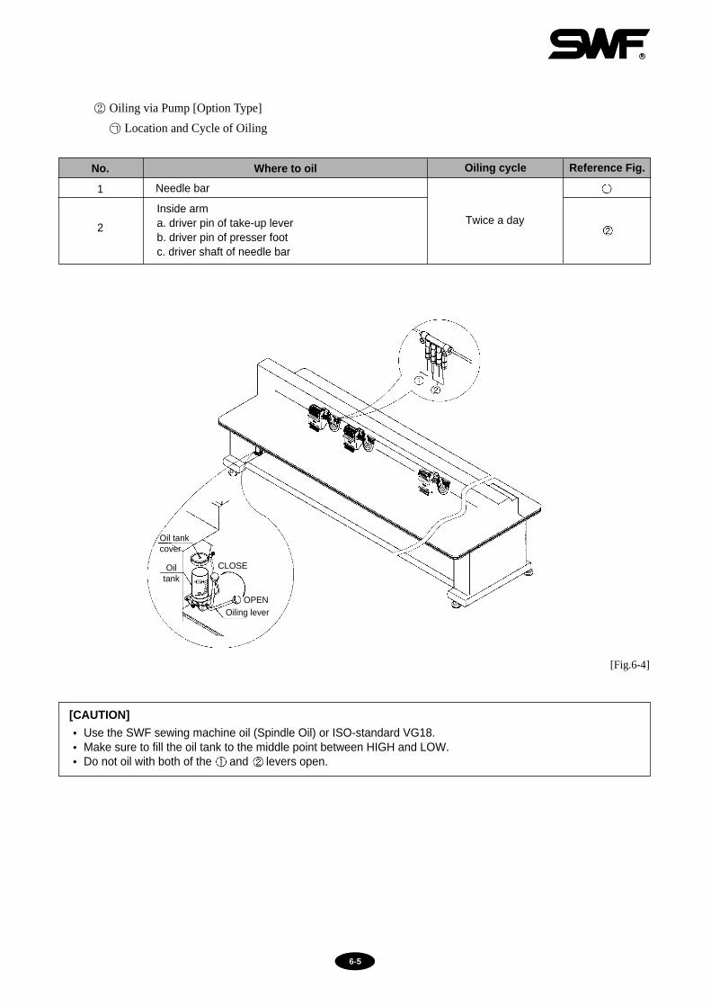
[CAUTION]• Use the SWF sewing machine oil (Spindle Oil) or ISO-standard VG18.• Make sure to fill the oil tank to the middle point between HIGH and LOW.• Do not oil with both of the and levers open.
② Oiling via Pump [Option Type]
㉠ Location and Cycle of Oiling
[Fig.6-4]
2
1
Inside arma. driver pin of take-up lever b. driver pin of presser foot c. driver shaft of needle bar
Needle bar
Twice a day
Where to oil Oiling cycle Reference Fig.No.
CLOSE
OPENOiling lever
Oiltank
Oil tankcover

6-6
Use high-quality mineral-based lithium grease.
[CAUTION]Regular greasing prevents machine noise and abnormal wear-out.
③ Grease supply
[Fig.6-5]
1
2
3
Inside the armTake-up lever drive cam Needle bar drive camNeedle bar controller
Driving plate for the upper thread holder
Hook gear and lower gear in the rotary hook base Once in 3 months
Once in 3 months
①
②
③
④
⑤⑥
Once in 3 months
Once in 3 months
Where to Grease Greasing cycle Reference Fig.NO
Make sure to turn OFF the main power during the grease supply.
CAUTION
⑤
⑥
⑦
Trimming cam driver box④
⑨
⑧
①
②
③
Places for supplying synthetic TM grease
1 Gears in the blade cam and trimming cam box ⑦Once in 3 months
2 Color change cam, color change head roller ⑧Once in 3 months
3 Hinge screw ⑨Once in 1 months
Where to Grease Greasing cycle Reference Fig.NO

6-7
Use lithium-type grease (JIS No.2) - Albania No.2.
[CATUION] Do NOT grease the parts not indicated (needle bar, hook, etc.)
[Fig.6-6]
1
2
3
4
X-axis LM guide (2 on each side)
Y-axis LM guide (2 on each side)
Sub Y drive LM guide (1 on one side)
Head drive LM guide
Once in 2 months
Once in 2 months
Once in 2 months
Once in 2 months
Where to Grease Greasing cycle Reference Fig.NO
Turn OFF the main power during the grease supply.CAUTION
Timing belt grease hole Timing belt
grease holegrease hole2 sides
LM Guide Rall
X-axis
Bed #2
X-axis LM guide (4 spots) Y-axis LM guide (4 spots)
Sub Y drive LM guide (1 spots) Head drive LM guide (upper cover opened)
Where to grease
Where togrease
Wheretogrease

6-8
6-4) DRIVE BELT TENSION
Too weak or too tight tension on the drive belt may cause machine malfunction or damages (abnormal wear-out ofdrive unit). Inspect the driver belt on a regular basis.
[CAUTION]Inspect the tension in the direction of the arrows in the picture below.
[Fig.6-7]
Location for inspection
Belt on main shaftmotor
Belt on main shaftmotor
Others
Inspection cycle
Once in 3months
Once in 3months
Once in 3months
Reference
check belt tension
check for belt crack
check for belt wear-out
check for bearing damage
check for wear-outs of rotating & sliding parts
NO
CAUTION
Turn OFF the main power when inspecting drive belt tension.
1
2
3
Idler
X frame plate
Driven pulley
Tension adjusting screw
Tension base screw
LM block plate screwTension adjusting screw
LA block plate
X-drive motor

7-1
MACHINE ADJUSTMENTS
CHAPTER 7
7-1) ADJUSTING THE TRIMMERS
7-1-1) Adjusting the Position of the Trimming Cam (Insert Angle of Movable Blade)
The movable blade is started by the trimmer cam in the angle it is inserted. As one of the basic trimmingfunctions, it arranges the upper thread tails in the needle after trimming.
1) Adjusting the position of the movable blade
① Check if the movable blade is in the correctposition.
② Cutting point of the movable blade should beinserted 1mm at the end of the fixed blade.Incorrect position of the movable blade cancause trimming errors or deviation of the upperthread.
③ Unfasten the crank screw to adjust the locationof the movable blade (see [Fig.7-1]).
2) Adjusting the angle of the movable blade
① Unfasten two screws on the blade cam. Adjustthe upper shaft rotary angle at 290°.
② Insert the trimming cam roller into the trimmingcam. Turn the cam and when the roller alignswith the curve of the cam, fasten the two screwsback.
③ Run the manual handle and check if the movableblade is well-inserted at 290°. Always checkafter the adjustment.
[Fig.7-1]
WARNING
Turn OFF the main power when adjusting the machine.
app. 1mm
Screw
Trimmingdrive crank
Blade cam
RollerRol
ler
Direction ofcammovement
[Fig.7-2]

7-2
7-1-2) Adjusting Blade Tension
Make sure to check and adjust the cross-tension of the movable and the fixed blades after replacement or repair.
① Checking the cross tensionManually move the movable blade and cut the upperand the lower threads. Check the cross-section of thethread cut.
② Adjusting the cross tensionAdjust the cross tension using fixed blade tensioncontrol screws (see [Fig.7-3]). Manually move themovable blade and adjust that it crosses in parallel withthe cutting line of the fixed blade from its entry pointto its return point.
[NOTE]Avoid excess cross-tension. It may cause the movable blade to wear out from overload at its entry orreturn point.
[Fig.7-3]
[Fig.7-4]
Movable blade
Tensioncontrolscrew
Fixed blade
Sensor
Sensor screw
Sensor
2mm
1mm
7-2) ADJUSTING THE TRIMMER RETURNSPRING
1) Function
The trimmer return spring detects if the movable bladereturns to the correct position after trimming. If themachine operates without the blade returned to its correctposition, the needle and the blade may be damaged. Thetrimmer return spring detects and stops the machine if theblade has not returned.
2) Adjustment
① Unfasten the spring shaft screw so that the center of thespring hole is around 2mm away from the surface towhich the screw is attached (see [Fig.7-4]). Save thelocation of the spring. Turn the spring holder #1 toadjust the tension of the return spring and refasten thescrew.
② Adjust the return spring so that the surface and thespring are around 1mm apart.
7-3
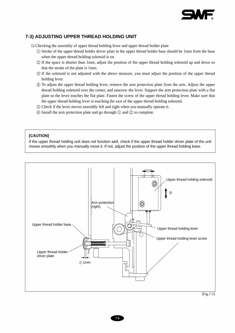
7-3) ADJUSTING UPPER THREAD HOLDING UNIT
1) Checking the assembly of upper thread holding lever and upper thread holder plate① Stroke of the upper thread holder driver plate in the upper thread holder base should be 1mm from the base
when the upper thread holding solenoid is on.② If the space is shorter than 1mm, adjust the position of the upper thread holding solenoid up and down so
that the stroke of the plate is 1mm.③ If the solenoid is not adjusted with the above measure, you must adjust the position of the upper thread
holding lever. ④ To adjust the upper thread holding lever, remove the arm protection plate from the arm. Adjust the upper
thread holding solenoid over the center, and unscrew the lever. Support the arm protection plate with a flatplate so the lever touches the flat plate. Fasten the screw of the upper thread holding lever. Make sure thatthe upper thread holding lever is touching the axis of the upper thread holding solenoid.
⑤ Check if the lever moves smoothly left and right when you manually operate it.⑥ Install the arm protection plate and go through ① and ② to complete.
[CAUTION]If the upper thread holding unit does not function well, check if the upper thread holder driver plate of the unitmoves smoothly when you manually move it. If not, adjust the position of the upper thread holding base.
[Fig.7-5]
Upper thread holding solenoid
Upper thread holding lever
Arm protection(right)
Upper thread holding lever screw
1mm
Upper thread holder base
Upper thread holderdriver plate

7-4
7-4) PICKER ADJUSTMENT
If the position or the starting height of the picker is incorrect, the machine may not be able to separate the upperand the lower thread and cut them both, resulting in short upper thread.
① Adjusting the picker positionManually move the picker so it touches the bobbin. Using the picker screws, adjust so the tip of the picker isin the correct position as in [Fig.7-5].
② Adjusting the starting heightLoosen the screw for the picker stopper and adjust the picker to be 0.2~0.5mm apart from the bobbin when thepicker is pressed. Make left and right adjustments for the picker stopper. When all the adjustments are done,tighten the screw for the picker stopper.
③ Adjusting picker standby positionUnfasten the screws on the picker solenoid cover. Adjust the position of the solenoid cover so that the tip ofthe picker is around 20mm away from the bobbin.
Picker screw
Correct positionof the picker
Picker
Bobbin case
[Fig.7-6]
Picker
Screws on the picker solenoid cover
Picker solenoid
[Fig.7-7]
[Fig.7-8]
Picker stopper
[CAUTION] After adjusting the picker standby position, check if the bobbin case moves smoothly.

7-5
7-5) ADJUSTING UPPER THREADHOLDER
① Adjusting the sensor springs (when wiperdoes not return) Ⓐ Open the wiper motor cover. Of the two
sensor rings, align the center of the rearsensor spring with #1 carve on the blockon the shaft. Align the center of the frontsensor spring with #2 carve on the block.
Ⓑ Adjust so that the head of the sensorspring is 1-1.2 mm apart from the wiperreturn sensor. Make sure to check if thewiper return sensor blinks.
[Fig.7-9]
② If the wiper does not operate smoothly, unfasten the screws on the drive link. Move the wiper lever up and downand unfasten the bracket screws so the wiper is not loaded by the upper thread holder bracket. Fasten the screwsback when the wiper moves smoothly.
③ After the adjustment, run the color change function to check if the wiper operates well at each needle bar.
④ If trimming error or jump error occurs on a certain head during the embroidery, run the wiper clutch to protect theembroidery and the wiper. • Press and turn the wiper clutch counterclockwise to run it. Turn it clockwise to stop.
[Fig.7-11]
Wiper return sensor
Rear sensor spring
Front sensor spring
#2 carve
#1 carve
Sensoradjustment ring
Cam block
[Fig.7-10]Upper thread holding bracket
Bracket screw
Driver ring crank
Wiper clutch

7-6
7-6) ADJUSTING LOW-NOISE PRESSER FOOT
1) Assembly of Presser Foot Cam ① Set the main shaft at 178° and install two reference pins (ф3) into the assembly hole of the presser foot
driver cam (ф3) as shown in [Fig.7-12]. Insert the pins then into the assembly hole of the take-up leverdriver cam.
② Adjust the presser foot driver cam to where the reference pins freely move left and right. Fix the threescrews (M4×L35).
[CAUTION] 1. The assembly pin should smoothly move right and left with the three screws fastened. 2. The assembly unit and the assembly pin are not for commercial sale.3. Contact your SWF dealer if you must adjust the location of the cam.
[Fig.11-12]
Reference pins ( 3)
Hole ( 3)
Presser footdrive cam
Take-up leverdrive cam

7-7
2) Adjusting the Height of the Presser Foot ① Check the relationship between the presser foot
and the needle/embroidery material. Turn themain shaft lever to position the needle at thelowest point (178°). Remove the head cover andunfasten the screws on the presser foot so itmoves up and down. Place a 1mm-thick gaugeon the needle plat and lightly press the presserfoot. Fasten the screws snugly when the presserfoot touches the gauge.
7-7) Relationship between Presser Foot andNeedle
1) Relationship between Presser Foot, Needle, andEmbroidery MaterialFor stable stitching, the presser foot must bepressing the embroidery material before the needlepierces into the material. The same is true for whenthe needle comes out of the material.
2) When the Presser Foot is Too High① Needle In
[Fig.7-15] shows the presser foot fails to pressthe work material when the needle pierces intothe fabric, causing an unstable needlework.
② Needle Out[Fig.7-16] shows the presser foot fails to press the work material when the needle comes out of the fabric.The embroidery material is lifted up along with the needle, making a gap between the fabric and the needleplate. This may cause thread breaks, skipped stitches, or unstable stitching.
[Fig.7-13]
Presser footholder
Presser footNeedle plate
Screw
1mm
[Fig.7-14]
Presser foot
Needle plate
Embroiderymaterial
Needleout
Needle in
[Fig.7-16]
Needle Out
[Fig.7-15]
Needle In

7-8
7-8) CORRECT POSITION OF NEEDLE
① Make sure to check the position of the needle - it may change during machine delivery or leveling. First checkif the needle is bent. Then turn the main shaft lever to set the shaft at around 130°. Position the needle at thelower dead stop and check if the needle is at the center of the needle hole on the plate.
② If the needle is not in the correct position, unscrew the brackets (two screws) to adjust the head and the needle(see [Fig.7-17]).
[Fig.7-17]
L-wrench
Bracket screws
Head
Needle plate
Needle plate
Needle plate
[CAUTION] Check the needle position on all heads.

7-9
7-9) ADJUSTING HALF-TURN FILM FOR COLOR CHANGE
① (For automatic color change) If the needle is not at the center of the needle hole on the plate, turn the lever andadjust so that the roller is on the center of the color change cam on the straight line. Open the cover of the half-turn sensor and align the center of the half-turn sensor with the center of the film (see [Fig.7-18(a)]).
[CAUTION]Manual color change must be performed at the upper shaft angle of 100°. Manual color change at the upper shaft angles other than 100°may cause damage on the controllerand the take-up unit.
[Fig.7-18]
Half-turn sensorHalf-turn sensor
Color change cam

7-10
7-10) JUMP MOTOR ADJUSTMENT
Adjustment is required for new or malfunctioning jump motor.
1) Adjusting the Standby Position (adjustingmotor base)① Unscrew motor base ([Fig.7-19]) and
adjust so that the jump crank roller is0.3mm away from the controller. Fastenthe screw.
② If the gap is wider than 0.3mm, theneedle may not jump well. If the gap isnarrower than 0.3mm, the jump willcause noise.
2) Adjusting Jump Manual Clutch ① Jump manual clutch is used to turn the
head off mechanically. If the clutch leverdoesn’t function properly, check theclutch assembly.
② First, pull the clutch lever forward andcheck if the carve on the clutch base is inline with the center of the clutch pin andthe center of the motor shaft when instandby (see [Fig.7-20]). If not, unscrewand adjust the clutch body with the jumpcrank roller attached to the stopper.Fasten the screw back.
③ Pull the clutch lever forward and check ifthe clutch body and the stopper arecompletely attached. If not, adjust thestopper to be completely attached to thebody.
[Fig.7-19]
Jump crank roller
Controller
Motor base screw
0.3mm
[Fig.7-20]
Jumpmanualclutch
shaft
Stopper
Clutchlever
A side
Stopper
Center of motor Manual clutchbase
Jumpmanual
clutch
CAUTION
1. If you will not be using the head with the head ON/OFF switch, make sure to use the jumpmanual clutch lever.
2. If the A side of the jump manual clutch does not touch the stopper, when you run the electricjump you will hear a noise.

7-11
7-11) ADJUSTING DRIVE BELT TENSION
7-11-1) Y-Axis Timing Belt
① Push the X frame plate to the driven pulley ([Fig.7-21]) and check the drive belt tension on the Y-axis. Use thesound wave tension gauge.
② Tension on the Y-axis belt should measure as below on the sound wave measurer when you pluck the middle ofthe belt between the X-Y link bracket and the drive pulley with your finger.
③ Input data for the sound wave tension measurer:
④ Unfasten the tension base screws. Turn the bolts to adjust the tension. Turn clockwise to increase andcounterclockwise to decrease the tension.
[CAUTION]Specification of Drive Belt Tension Adjuster
Model: U-305 Series Sound Wave Belt Tension Gauge - Standard Manufacturer: UNITTA
[CAUTION]Drive belt tension can be adjusted only by trained SWF engineers.Make sure to turn OFF the machine during the adjustment.
[Fig.7-21]
Tension bolts
X-Y link bracket
Driven pulley
Tension base screw
Weight
Wide
Span
Tension measurement
4.0gf/m
25.0mm/#R
480mm
18kgf
3.8gf/m
35.0mm/#R
510mm
18kgf
4.0gf/m
25.0mm/#R
900mm
18kgf
3.8gf/m
35.0mm/#R
535mm
25kgf
3.8gf/m
35.0mm/#R
510mm
18kgf
3.8gf/m
35.0mm/#R
924mm
21kgf
3.8gf/m
35.0mm/#R
512mm
21kgf
Type 2-head 4-head6-head
compact
6-head
2 at both ends,narrow
2 in the middle,wide
8-head
2 at both ends,narrow
2 in the middle,wide

7-12
7-11-2) X-Axis Timing Belt
① Push the frame plate fully to the right ([Fig.7-22]). Check the drive belt tension on X-axis using the soundwave tension gauge.
② Tension on the X-axis timing belt should measure as below on the sound wave measurer when you pluck themiddle of the belt with your finger.
③ Input data for the sound wave tension measurer:
7-11-3) Timing Belt on Main Shaft Motor
① Tension on the timing belt of the main shaft motor should measure as below on the sound wave measurer whenyou pluck the middle of the belt with your finger.
② Input data for the sound wave tension measurer:
④ Unscrew LM block plate. Turn the tension bolts toadjust the tension. Turn clockwise to increase andcounterclockwise to decrease the tension.
[Fig.7-23]
[Fig.7-22]
Weight
Type
004.0 gf/m 004.0 gf/m
015.0 mm/#R 015.0 mm/#R
0590 mm 0590 mm
18 Kgf 19 Kgf
Wide
Span
Tension measurement
4-head 6-head & 8-head
LM blockplate screw
Tension boltLM block plate
X-drive motor
Idler
Weight
Type
004.0 gf/m 004.0 gf/m
020.0 mm/#R 030.0 mm/#R
0405 mm 0405 mm
18 Kgf 18 Kgf
Wide
Span
tension measurement
4-head 6-head & 8-head
③ Unscrew the idler and adjust it right and leftto get the right tension. Turn the idler left toincrease the tension and right to decrease thetension.

7-13
7-12) LAMP (OPTIONAL)
7-12-1) Lamp Socket Adjustment (4-head)
Standard lamp for SWF machines measures 580mm in length. If you have to use 590mm lamp for certainpurposes, adjust the lamp in the following order.① Unfasten the three screws on the socket.② Push the lamp socket fully to the right of the shell.③ Install a new lamp and adjust the socket according to the length of the lamp. Fasten the socket screws.
7-12-2) Disassembling Cable Cover (4-head)
If you have to open the cable cover for machine repair, etc., follow the procedures below.① Slightly unfasten the six screws underneath the lamp bracket.② Take out the lamp and open the cover. Do repair or other necessary work.③ When finished, re-assemble the cover, push the lamp forward and fasten the bracket screws.
[Fig.7-25]
[Fig.7-24]
Lamp
Socket
Lamp bracket
Lamp bracket screw
Lamp bracketslider
Lamp bracketslider screw
Lamp
Cable cover

8-1
TROUBLESHOOTING
CHAPTER 8
CAUTIONDANGER Inspect/repair the machine by the guideline when in machine failures.
Error Type Cause
Loose belt tension / beltdamage
Power failure or short-circuitof fuse
Failure to sense signals forneedle position or 1rotation
Red light on X/Y drive box
Machine does not start atSTART
Loose tension on maindriver belt
Incorrect position ofencoder or bad encoder
Adjust belt tension / change belt
Check fuse in main shaft motorand change fuse
Run manual color change andcheck if signal lamps (needle setlamp & needle position lamp)blinks at correct needle position.Adjust the half-turn film.
Address the cause and pressRESET. Check if the lamp turnsgreen.
Check connection of STARTswitch
Adjust belt tension
Adjust encoder position orchange encoder
Inspection & Repair Reference
Operation failure
Incorrect StopPosition

8-2
Error Type Cause
① Incorrect position of needlestop
② Failure to sense signals forneedle position or 1 rotation
③ Incorrect position of needlebar
④ Incorrect position of take-uplever
⑤ Bad connection
Inspection & Repair
Refer to user’s manual
Run manual color change andcheck if signal lamps (needleset lamp & needle positionlamp) blinks at correct needleposition. Adjust the half-turnfilm.
Set it to the correct position
Adjust so take-up lever is inline with other levers in stopposition (upper shaftangle:100°)
Change fuse F3 in joint boardor check connection
Set main shaft angle back at100°, if you manually movedit for cleaning, inspection orrepair.
※ Adjusting position oftake-up leverUnscrew the lever andadjust so it is in line withother take-up levers onthe guide rail.
Check fuse spec.
Reference
Bad ColorChange
take-upleverscrew
take-uplever

8-3
Error Type Cause
Poor connection of take-up spring and threaddetector plate
Poor connection & qualityof tension adjusting plate
Bad Motor and bad motorwiring
Bad connection
Switch failure on tensionadjusting board and badcircuit board
Bad tape
Inadequate tension on X-Y belt
Foreign substance in X-Yrail
Failure of X/Y driver board
Heavy load on frame
Inspection & Repair
Clean the spring and the plate,or adjust the spring tension.
Check the plate connection andchange the circuit board
Check wiring and change motor
Check connection
Change switch and circuit board
Correct tape
Adjust tension
Clean the rail
Change circuit board
Reduce speed of main shaft
Reference
Poor detectionof upper thread
Bad jump
Bad stitchquality

8-4
Error Type Cause
Stitch is too small/densefor thread
Frequent thread break inthe same spot
Inadequate needle sizefor thread
Needle damage (bent,dent, worn)
Incorrect needleinstallation (height,direction, etc.)
Dirty needle (adhesive,etc.)
Inspection & Repair
Re-punch design tape
Re-punch after checkingdesignCorrect the stitches onoperation box
Change needle
Change needle
Re-install needle
Clean or change needle andhook
Check design
Use minimum adhesive forapplique
Reference
Thread breaks

8-5
Error Type Cause
Bad thread (weak,uneven thickness, poorlytwisted, old)
Right-twisted thread
Excessive thread tension
Tension imbalancebetween upper and lowerthreads
Excessive tension &stroke on take-up spring
Inspection & Repair
Change thread
Change to left-twisted thread
Adjust tension
Adjust tension and stroke
Check the thread used.How to select thread.•Select soft thread with
ever thickness andstable tension.
•Choose left-twistedthread.
Z-direction: left twistS-direction: right twist
left-twist preventsunraveling of the upperthread in thecounterclockwise rotationof the hook
Reference

8-6
Error Type Cause
Dent on thread path onhook and bobbin case
Narrow space betweenhook holder and groovefor hook holder (on hook)
Insufficient oil in hook
Poor timing of needle andhook
Incorrect lower dead stop
Dent on thread path
Fabric moves on theframe
Inadequate height ofpresser foot(does not press the workmaterial)
Inspection & Repair
Remove dent or change thecase
Adjust space
Oil the raceway of hook
Adjust timing
Adjust the lower dead stop
Check:•Thread path in presser foot•Around needle hole on
needle plate•Thread guide on the head•Thread path in tension
adjuster
Fix the material firmly
Adjust height
Set it at 0.5-0.7mm forsmooth feeding of upperthread
Reference

8-7
Error Type Cause
Bent needle
Inadequate needle sizefor thread
Incorrect installation ofneedle
Poor timing of needle andhook
Large gap betweenneedle groove and hookpoint
Incorrect lower dead stop
Damaged hook point
Thread feeding isinterfered
Inadequate thread (twist, elasticity, andflexibility)
Excessive tension orstroke on the take-uplever spring
Fabric moves with needle- weak or damagedpresser foot (spring)
Inspection & Repair
Change needle
Adjust installation
Adjust timing
Adjust the lower dead stop
Use whetstone to adjust hookpoint or change hook
Adjust thread tensionFor upper thread, changebobbin or bobbin case
Select right thread forembroidery
Adjust stroke or tension
Change presser foot spring
Reference
Skipped Stitches

8-8
Error Type Cause
Weak upper threadtension
Uneven upper threadtension due to foreignsubstances
Weak lower threadtension
Uneven lower threadtension
Thread thickness
Poor timing of needle andhook
Insufficient oil in hook
Bent needle
Bad quality needle
Tip of the needle is wornor bent
Needle touches the hookpoint
Needle touches the hookpoint
Incorrect installation ofneedle
Needle touches theneedle hole on the plate
Inspection & Repair
Adjust tension
Clean main and sub tensionadjusters in the thread tensionadjusting plate
Adjust tension
Clean bobbin case and checktension on bobbin spring
Change to quality thread
Adjust timing
Oil the raceway of hook
Change needle
Space the needle and the hookpoint
Correct the installation
Check if needle plate isunscrewedAdjust the position of theneedle bar
Reference
Poor stitchtension
Needle breaks

8-9
Error Type Cause
Excessive thread tension
Excessive pressure ofpresser foot
Needle failure - worn out/damaged needletip needle is too large forthread
Needle hole is too largefor needle
Poor connection/quality oftrimming solenoid
Bad connection
Trimming driver TRdamaged
Inspection & Repair
Adjust tension
Change presser foot spring
Change needle
Use adequate size of needle
Check and change solenoid andsolenoid connection
Check connection
Change joint board
SWF/ needle holesare 2.0mm
Reference
Puckering
Trimming failure

8-10
Error Type Cause
Poor connection of sensor
Bad circuit board
Bad sensor or sensorposition. Dirty area around thesensor.
Movable blade is too fastor too slow to separatethe upper thread
Incorrect position of picker
Picker failure
Upper thread is too short
check main and subtension adjuster
dent or damage tomovable blade
Lower thread is too short
doesn’t unwindsmoothly
too weak or too elastic
Inspection & Repair
Check connection
Change circuit board
change sensorclean around the sensoradjust location of the sensorunit
Adjust insert angle of movableblade (295°)
Adjust picker position
Check and change fuse F1, F3 Check/change solenoid andsolenoid connectionCheck connection and changejoint board
Adjust upper thread tension
remove dent using whetstone orsandpaper or change movableblade
adjust or change bobbin casespring
clean/check for dent in threadguide on the bobbin case
Change lower thread
Check fuse spec.
Too short lower threadcannot make stitchesright after trimming
Reference
Trimmer returnfailure
Short upperthread aftertrimming due toseparationfailure
Thread breakbefore trimming
Check for dent

8-11
Error Type Cause
Upper thread is trimmedtoo short and comesunthreaded
Upper thread is trimmedtoo long and thread tailremains on the embroidery
Failure of movable andfixed blades
Loose cross tension of theblades
Movable blade damaged
Incorrect return position ofmovable blade
Poor connection/quality ofsolenoid
Bad connection
Poor quality circuit board
Short strokes of upperthread holder
Upper thread holderoverloaded
Cable fuse short-circuit
Circuit fuse short-circuit
Expired lifespan of thelamp
Inspection & Repair
check upper thread tensionset or lengthof trimmed thread in data set-up
set or length of trimmed thread indata set-upif upper thread is held due tonarrow velcro space in upperthread holder, clean thevelcro
Check screws and crank driverclamp screws of the movableblade
Check tension of fixed blade
Change movable blade
Adjust the position of movableblade
Check/change solenoid &connection
Check connection
Change thread detecting platein sub controller
Adjust stroke
Adjust the workload
Replace the cable fuse
Replace the con. box lampass’y fuse
Replace the fluorescent lamp
ShortMedium
MediumLongThe default is .
Change fuse spec
Change fuse spec
Change fuse spec
Medium
Reference
Short upperthread aftertrimming
Thread is not cut(at specifichead)
Failure of upperthread holdersolenoid
Failure to holdupper thread
When thefluorescent lampis not properlyoperating, oneof the followingmight be thereason:

9-1
BLOCK DIAGRAM
CHAPTER 9
1) BLOCK DIAGRAM OF SWF/E-U SERIES (Excluding SWF/E-UH 1508-45)
9-2
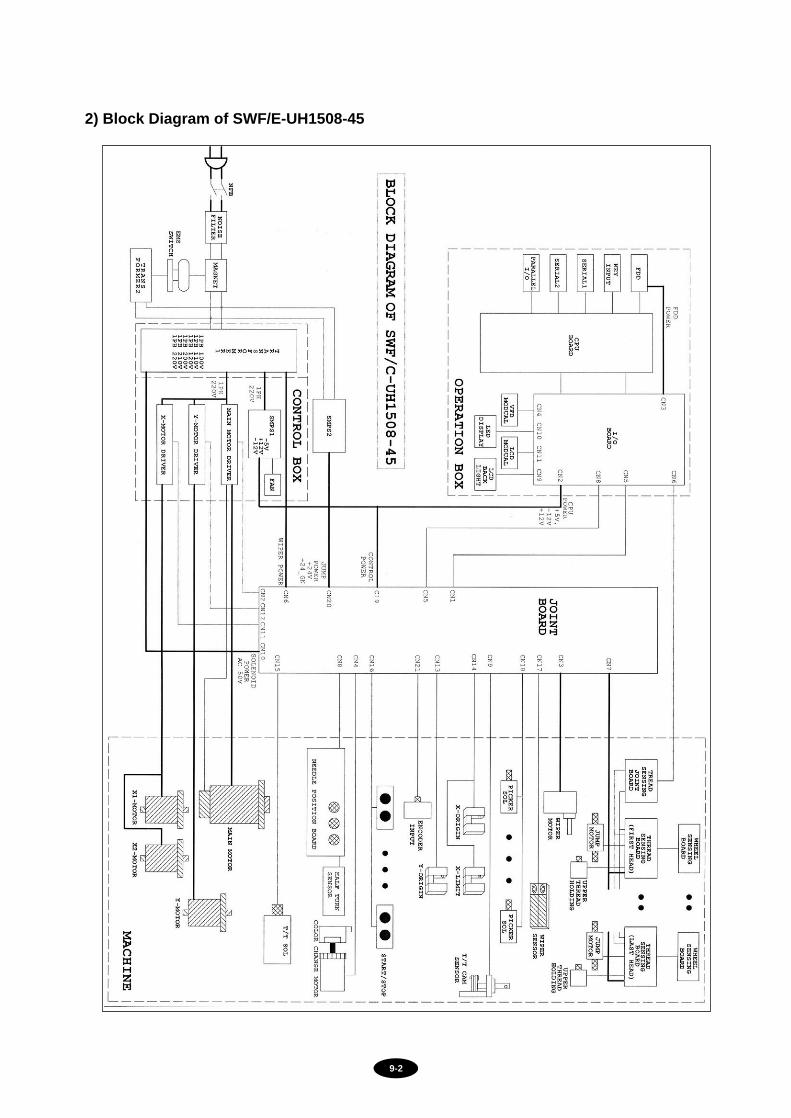
2) Block Diagram of SWF/E-UH1508-45