User´s Model RAMC Manual Metal Short Stroke ROTAMETERUser´s Model RAMC Manual Metal Short Stroke...
144
User´s Manual Model RAMC Metal Short Stroke ROTAMETER IM 01R01B02-00E-E Rota Yokogawa GmbH & Co. KG Rheinstr. 8 D-79664 Wehr Germany IM 01R01B02-00E-E ©Copyright 2003 (RYG) 13th edition, April 2016 (RYG
Transcript of User´s Model RAMC Manual Metal Short Stroke ROTAMETERUser´s Model RAMC Manual Metal Short Stroke...
User´s
Manual
Model RAMC
Metal Short Stroke ROTAMETER
IM 01R01B02-00E-E
Rota Yokogawa GmbH & Co. KGRheinstr. 8D-79664 WehrGermany
IM 01R01B02-00E-E©Copyright 2003 (RYG)
13th edition, April 2016 (RYG

Blank Page
<CONTENTS> i
IM 01R01B02-00E-E 13th edition April 01, 2016 -00All Rights Reserved. Copyright © 2003, Rota Yokogawa
Contents
1. Introduction .........................................................................................1-1
1.1 For Safe Use of Rotameter RAMC .................................................................1-2
1.2 Warranty .............................................................................................................1-3
1.3 Notices regarding EMC ....................................................................................1-3
1.4 General description .........................................................................................1-4
1.5 Principle of measurement ..............................................................................1-4
1.6 Overview ...........................................................................................................1-5
2. Precautions .........................................................................................2-1
2.1 Transportation and storage ............................................................................2-1
2.2 Installation .......................................................................................................2-1
2.3 Pipe connections ............................................................................................2-1
3. Installation ..........................................................................................3-1
3.1 Installation in the pipeline .............................................................................3-1
3.2 Wiring of electronic transmitter (-E, -H) and limit switches (/K_) ..............3-2
4. Start of operation ...............................................................................4-1
4.1 Hints on flow rate measurement ...................................................................4-1
4.2 Pulsation and pressure shock .......................................................................4-1
4.3 Start of operation of electronic transmitter .................................................4-1
5. Limit switches (Option /K[]) ...........................................................................................5-1
<CONTENTS>ii
IM 01R01B02-00E-E 13th edition April 01, 2016 -00 All Rights Reserved. Copyright © 2003, Rota Yokogawa
6. Electronic Transmitter (-E) .................................................................6-1
6.1 Operation principle .........................................................................................6-1
6.2 Parameter setting ............................................................................................6-1
6.2.1 Selection of indication function (F11) ............................................................... 6-4
6.2.2 Setting the unit (F12 / F13) ................................................................................. 6-5
6.2.3 Totalizer reset (F14) ............................................................................................. 6-7
6.2.4 Selection of temperature unit (F15) ................................................................... 6-7
6.2.5 Setting of damping (F2-) ..................................................................................... 6-8
6.2.6 Selection / Adjustment 4-20 mA / 0-20 mA (F3-) .............................................. 6-8
6.2.7 Pulse output (F34) (Option /CP) ......................................................................... 6-9
6.2.8 Error messages (F4-) ......................................................................................... 6-12
6.2.9 Manual adjustment (F5-) ................................................................................... 6-13
6.2.10 Revision indication (F61/F62) ......................................................................... 6-16
6.2.11 Current output test (F63) ................................................................................. 6-16
6.2.12 Switching between standard / Indicator on extension (F64) ...................... 6-17
6.2.13 Master Reset (F65) ........................................................................................... 6-17
6.2.14 Float blocking indication (F7-) ........................................................................ 6-18
7. HART® - Communication .....................................................................................7-1
7.1 General .............................................................................................................7-1
7.1.1 Multidrop Mode in the case of using HART 5 .....................................................7-1
7.2 Connection .......................................................................................................7-2
7.3 HART5 Menu (Rev 01 DD rev 02) ................................................................7-3
7.4. Description of the HART5®- Parameter.........................................................7-6
7.4.1 Process variables ..................................................................................................7-7
7.4.2 Diagnostic- and Service-Menu .............................................................................7-7
7.4.3 Basic-Setup Menu ...............................................................................................7-13
7.4.4 Detailed-Setup Menu ...........................................................................................7-13
7.4.5 Review ..................................................................................................................7-15
<CONTENTS> iii
IM 01R01B02-00E-E 13th edition April 01, 2016 -00All Rights Reserved. Copyright © 2003, Rota Yokogawa
7.5 Maintenance ................................................................................................... 7-16
7.5.1 Function test ........................................................................................................7-16
7.5.2 Troubleshooting ...................................................................................................7-16
8. Service ..........................................................................................................8-1
8.1 Maintenance ....................................................................................................8-1
8.1.1 Function test ......................................................................................................... 8-1
8.1.2 Measuring tube, float ........................................................................................... 8-1
8.1.3 Explosion drawing .................................................................................................................8-2
8.1.4 Electronic transmitter .......................................................................................... 8-3
8.1.5 Exchange of EEPROM and scale ....................................................................... 8-3
8.1.6 Exchange of indicator .......................................................................................... 8-4
8.1.7 Troubleshooting .................................................................................................... 8-4
8.2 Template for sending back to service ..........................................................8-6
9. Technical Data ....................................................................................9-1
9.1 Model- and suffix-codes .................................................................................9-1
9.2 Options ............................................................................................................9-2
9.3 Specifications ..................................................................................................9-5
9.4 Dimensions and weights..............................................................................9-19
9.5 Temperature graphs for RAMC metal design, standard and intrinsic safe ..... ...............................................................................................................................9-22
10. Explosion-protected Type Instruments .......................................... 10-1
10.1 General .........................................................................................................10-2
10.1.1 Intrinsic safety ................................................................................................. 10-2
10.1.2 Flame proof ...................................................................................................... 10-2
10.2 Intrinsically safe ATEX certified components (/KS1) .................................10-3
10.2.1 Technical data .................................................................................................. 10-3
10.2.2 Installation ........................................................................................................ 10-4
10.2.3 Marking ............................................................................................................. 10-4
<CONTENTS>iv
IM 01R01B02-00E-E 13th edition April 01, 2016 -00 All Rights Reserved. Copyright © 2003, Rota Yokogawa
10.3 Intrinsically safe ATEX certified components for category 3G (/KS3) .....10-5
10.3.1 Technical data .................................................................................................. 10-5
10.3.2 Marking ............................................................................................................. 10-6
10.4 Intrinsically safe IECEx- certified components (/ES1) ..................................10-7
10.4.1 Technical data .................................................................................................. 10-7
10.4.2 Installation ........................................................................................................ 10-8
10.4.3 Marking ............................................................................................................. 10-8
10.5 Intrinsically safe IECEx- components for category 3G (/ES3) ...................10-9
10.5.1 Technical data .................................................................................................. 10-9
10.5.2 Marking ............................................................................................................. 10-9
10.6 Intrinsically safe INMETRO (Brazil) components (/US1) ................................10-10
10.6.1 Technical data .................................................................................................10-10
10.6.2 Installation .......................................................................................................10-10
10.6.3 Marking ............................................................................................................10-10
10.7 Intrinsically safe FM / CSA (USA + Canada) components (/FS1, /CS1) ......... 10-11
10.7.1 Electronic transmitter (/FS1 for USA, /CS1 for Canada) ..............................10-11
10.7.2 Limit switches option /K1 ... /K10 (/FS1 for USA)..........................................10-14
10.7.3 Limit switches option /K1 ... /K3 (/CS1 for Canada) .....................................10-14
10.8 Intrinsically safe NEPSI (China) certified RAMC (/NS1) .................................10-20
10.9 Intrinsically safe EAC (Russia, Belarus, Kazakhstan)certified RAMC (/GS1) 10-21
10.10 Flame proof and dust proof ATEX certified RAMC (/KF1) ..................10-22
10.10.1 Technical data ............................................................................................... 10-22
10.10.2 Installation .................................................................................................... 10-23
10.10.3 Operation ...................................................................................................... 10-23
10.11 Flame proof and dust proof IECEx certified RAMC (/EF1) .................10-24
10.11.1 Technical data ............................................................................................... 10-24
10.11.2 Installation ..................................................................................................... 10-25
10.11.3 Operation ....................................................................................................... 10-25
<CONTENTS> v
IM 01R01B02-00E-E 13th edition April 01, 2016 -00All Rights Reserved. Copyright © 2003, Rota Yokogawa
10.12 Intrinsically safe ATEX certified components in dust proof RAMC-housing (/KS2) ...................................................................................................................10-26
10.13 Intrinsically safe IECEx certified components in dust proof RAMC- housing (/ES2) ...................................................................................................................10-26
10.14 Flame proof and dust proof NEPSI (China) certified RAMC (/NF1) ....10-27
10.14.1 Technical data ............................................................................................... 10-27
10.14.2 Installation .................................................................................................... 10-27
10.14.3 Operation ...................................................................................................... 10-28
10.15 Flame proof EAC (Russia, Belarus, Kazakhstan) certified RAMC (/GF1) .10-28
10.15.1 Technical data ............................................................................................... 10-28
10.15.2 Installation .....................................................................................................................10-28
10.15.3 Operation ........................................................................................................................10-28
10.16 ATEX registrated non-electrical RAMC (/KC1) ...............................................10-29
10.16.1 Technical data ............................................................................................... 10-29
10.16.2 Safety Instructions ....................................................................................... 10-29
10.16.3 Marking ......................................................................................................... 10-29
10.17 EAC certified non-electrical RAMC (/GC1) .....................................................10-30
10.17.1 Technical data ............................................................................................... 10-30
10.17.2 Safety Instructions ....................................................................................... 10-30
10.17.3 Marking .......................................................................................................... 10-30
10.18 Flame proof and dust proof RAMC with Taiwan Safety Label .................... 10-31
11. Instructions for PED ....................................................................... 11-1
APPENDIX 1. SOFTWARE CHANGE HISTORY ................................. A1-1
<CONTENTS>vi
IM 01R01B02-00E-E 13th edition April 01, 2016 -00 All Rights Reserved. Copyright © 2003, Rota Yokogawa
APPENDIX 2. Safety Instrumented Systems Installation .................A2-1
A2.1 Scope and Purpose ....................................................................................A2-1
A2.2 Using RAMC for a SIS Application ...........................................................A2-1
A2.2.1 Safety Function.................................................................................................A2-1
A2.2.2 Diagnostic Response Time ..............................................................................A2-2
A2.2.3 Setup ..................................................................................................................A2-2
A2.2.4 Proof Testing .....................................................................................................A2-2
A2.2.5 Repair and replacement ..................................................................................A2-3
A2.2.6 Startup Time ......................................................................................................A2-3
A2.2.7 Firmware update ...............................................................................................A2-3
A2.2.8 Reliability data ..................................................................................................A2-3
A2.2.9 Lifetime limits ...................................................................................................A2-3
A2.2.10 Required parameter settings .........................................................................A2-3
A2.2.11 Environmental limits ......................................................................................A2-4
A2.2.12 Application limits ............................................................................................A2-4
A2.3 Definitions and Abbreviations ...................................................................A2-4
A2.3.1 Definitions .........................................................................................................A2-4
A2.3.2 Abbreviations ....................................................................................................A2-4
A2.4 Assessment results ....................................................................................A2-5
A2.4.1 Safety related parameters ...............................................................................A2-5
<1. INTRODUCTION> 1-1
All Rights Reserved. Copyright © 2003, Rota Yokogawa IM 01R01B02-00E-E 13th edition April 01, 2016 -00
1. Introduction
Before use, read this manual thoroughly and
familiarize yourself fully with the features,
operations and handling of Rotameter RAMC to have
the instrument deliver its full capabilities and
to ensure its efficient and correct use.
Notices Regarding This Manual
• This manual should be passed to the end user.• The contents of this manual are subject to change without prior notice.
• All rights reserved. No part of this document may be reproduced or transmitted in any form or by
any means without the written permission of
Rota Yokogawa (hereinafter simply referred to as
Yokogawa).
• This manual neither does warrant the marketability of this instrument nor it does
warrant that the instrument will suit a particular
purpose of the user.
• Every effort has been made to ensure accuracy in the contents of this manual. However, should
any questions arise or errors come to your
attention, please contact your nearest Yokogawa
sales office that appears on the back of this
manual or the sales representative from which
you purchased the product.
• This manual is not intended for models with custom specifications.
• Revisions may not always be made in this manual in conjunction with changes in specifications, constructions and/or components
if such changes are not deemed to interfere with
the instrument’s functionality or performance.
Notices Regarding Safety and Modification
• For the protection and safety of personnel, the instrument and the system comprising the
instrument, be sure to follow the instructions on
safety described in this manual when handling
the product. If you handle the instrument in a
manner contrary to these instructions, Yokogawa
does not guarantee safety.
• If this instrument is used in a manner not specified in this manual, the protection provided
by this instrument may be impaired.
• As for explosion proof model, if you yourself repair or modify the instrument and then fail to
return it to its original form, the explosion protected construction of the instrument will be
impaired, creating a hazardous condition. Be
sure to consult Yokogawa for repairs and
modifications.
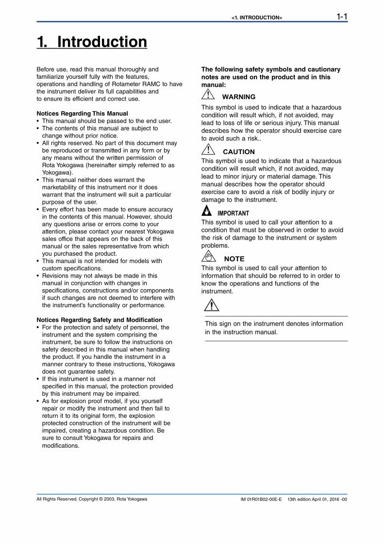
The following safety symbols and cautionary
notes are used on the product and in this
manual:
This symbol is used to indicate that a hazardouscondition will result which, if not avoided, may
lead to loss of life or serious injury. This manualdescribes how the operator should exercise care to avoid such a risk..
This symbol is used to indicate that a hazardouscondition will result which, if not avoided, may
lead to minor injury or material damage. This manual describes how the operator should
exercise care to avoid a risk of bodily injury or damage to the instrument.
This symbol is used to call your attention to acondition that must be observed in order to avoid
the risk of damage to the instrument or system
problems.
This symbol is used to call your attention toinformation that should be referred to in order to
know the operations and functions of the
instrument.
This sign on the instrument denotes information in the instruction manual.
WARNING
CAUTION
IMPORTANT
NOTE
<1. INTRODUCTION>1-2
All Rights Reserved. Copyright © 2003, Rota YokogawaIM 01R01B02-00E-E 13th edition April 01, 2016 -00
1.1 For Safe Use of Rota-meter RAMC
(0) General
• Working with bare skin should not be done.• Working with wet hand, body should not be
done.
(1) Installation
• Installation of the RAMC variable area flowme-
ter must be performed by expert engineer or skilled personnel. No operator shall be permitted to
perform procedures relating to installation.
• The RAMC flowmeter is a heavy instrument. Be careful that no damage is caused to personnel
through accidentally dropping it, or by exerting
excessive force on the RAMC flowmeter. • All procedures relating to installation must comply
with the electrical code of the country where it
is used.
(2) Wiring
• The wiring of the RAMC flowmeter must be per-
formed by expert engineer or skilled personnel. No operator shall be permitted to perform
procedures relating to wiring.
• When connecting the wiring, check that the supply voltage is within the range of the voltage
specified for this instrument before connect-
ing the power cable. In addition, check that
no voltage is applied to the power cable before
connecting the wiring.
• The protective grounding must be connected securely at the terminal with the mark to
avoid danger to personnel (only AC type).
(3) Operation
• Do not open the cover until the power has been off for at least 10 minutes because of electric
shock and hot temperatures inside. Only expert engineer or skilled personnel are permitted to
open the cover.
• When the RAMC flowmeter is processing hot fluids, the instrument itself may become ex-tremely hot. Take sufficient care not to get burnt.
If the fluid temperature is above 65°C it has to be ensured, that an easy touch by humans is
prohibited (e.g. by installation, by a barrier, by a
warning).
WARNING
• Where the fluid being processed is a toxic sub-
stance, avoid contact with the fluid and avoid inhaling any residual gas, even after the instru-
ment has been taken off the line for
maintenance and so forth.
(4) Maintenance
• Maintenance on the RAMC flowmeter should be performed by expert engineer or skilled person-
nel. No operator shall be permitted to perform any operations relating to maintenance.
• Always conform to maintenance procedures outlined in this manual. If necessary, contact
Yokogawa.
• Care should be taken to prevent the build up of dirt, dust or other substances on the display
panel glass. If these surfaces do get dirty, wipe
them clean with a soft dry cloth.
• Don’t open the cover in rainy weather• Don’t open the cover during power is connected
because of electric shock.
• The electronic assembly contains sensitive parts. Take care so as not to directly touch the electronic parts or circuit patterns on the board,
and by preventing static electrification using
grounded wrist straps when handing the
assembly.
(5) European Pressure Equipment Directive (PED)
• When using the instrument as a PED-compliant product, be sure to read Chapter 11 before use.
(6) Hazardous Duty Type Instruments • For explosion proof type instruments the
description in chapter 10 "EXPLOSION PRO-
TECTED TYPE INSTRUMENT" has priority to
the other descriptions in this instruction manual.
• All instruction manuals for ATEX Ex related products are available in English, German and
French. Should you require Ex related instruc-
tions in your local language, you should contact
your nearest Yokogawa office or representative.
• Only trained personal should install and maintain instruments in hazardous areas.
<1. INTRODUCTION> 1-3
All Rights Reserved. Copyright © 2003, Rota Yokogawa IM 01R01B02-00E-E 13th edition April 01, 2016 -00
1.2 Warranty• The warranty of this instrument shall cover the period noted on the quotation presented to the
Purchaser at the time of purchase. The Seller shall repair the instrument free of charge when
the failure occurred during the warranty period.
• All inquiries on instrument failure should be directed to the Seller’s sales representative from whom you purchased the instrument or your
nearest sales office of the Seller.• Should the instrument fail, contact the Seller specifying the model and instrument number of
the product in question. Be specific in describing
details on the failure and the process in which
the failure occurred. It will be helpful if
schematic diagrams and/or records of data are
attached to the failed instrument.
• Whether or not the failed instrument should be repaired free of charge shall be left solely to the
discretion of the Seller as a result of an inspection by the Seller.
The Purchaser shall not be entitled to
receive repair services from the Seller free
of charge, even during the warranty period,
if the malfunction or damage is due to:
• improper and/or inadequate maintenance of the instrument in question by the Purchaser.• handling, use or storage of the instrument in question beyond the design and/or specifications
requirements.
• use of the instrument in question in a location not conforming to the conditions specified in the
Seller’s General Specification or Instruction Manual.
• retrofitting and/or repair by an other party than the Seller or a party to whom the Seller has entrusted repair services.
• improper relocation of the instrument in question after delivery.
• reason of force measure such as fires, earthquakes, storms/ floods, thunder/lightning, or other reasons not attributable to the instrument
in question.
1.3 Notices regarding EMCThe Rotameter RAMC is conform to the European
EMC Guideline and fulfills the following standards:
- EN 61326-1The RAMC is a class A product and should be
used and installed properly according to the EMC
Class A requirementsAlthough the transmitter
has been designed toresist high frequency elec-
trical noise, if a radiotransceiver is used near the
transmitter or itexternal wiring, the transmitter may be affected byhigh frequency noise pickup. To test for sucheffects, bring the transceiver in use
slowly from adistance of several meters from the
transmitter,and observe the measurement loop for
noiseeffects. Thereafter, always use the transceiver outside the area affected by noise.
<1. INTRODUCTION>1-4
All Rights Reserved. Copyright © 2003, Rota YokogawaIM 01R01B02-00E-E 13th edition April 01, 2016 -00
1.4 General descriptionThis manual describes installation, operation and maintenance of the RAMC. Please read it carefully before using this device.
Further, please note that customer features are not described in this manual. When modifying specifications,construction or parts, this manual is not necessarily revised unless it can be assumed that these changes will
impair RAMC functions or performance.
All units are thoroughly tested before shipping. Please check the received units visually to ensure that theyhave not been damaged during transport. In case of defects or questions please contact your nearest
YOKOGAWA service centre or sales office. Please describe any defect precisely and indicate model code aswell as serial number.
YOKOGAWA refuses any liability for units which have been repaired by the user without prior consent and do
not meet the specifications as a consequence.
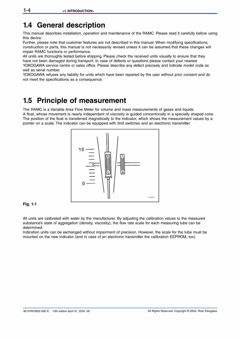
1.5 Principle of measurementThe RAMC is a Variable Area Flow Meter for volume and mass measurements of gases and liquids.A float, whose movement is nearly independent of viscosity is guided concentrically in a specially shaped cone.The position of the float is transferred magnetically to the indicator, which shows the measurement values by a pointer on a scale. The indicator can be equipped with limit switches and an electronic transmitter.
Fig. 1-1
All units are calibrated with water by the manufacturer. By adjusting the calibration values to the measuredsubstance’s state of aggregation (density, viscosity), the flow rate scale for each measuring tube can bedetermined.
Indication units can be exchanged without impairment of precision. However, the scale for the tube must bemounted on the new indicator (and in case of an electronic transmitter the calibration EEPROM, too).
F10.EPS
<1. INTRODUCTION> 1-5
All Rights Reserved. Copyright © 2003, Rota Yokogawa IM 01R01B02-00E-E 13th edition April 01, 2016 -00
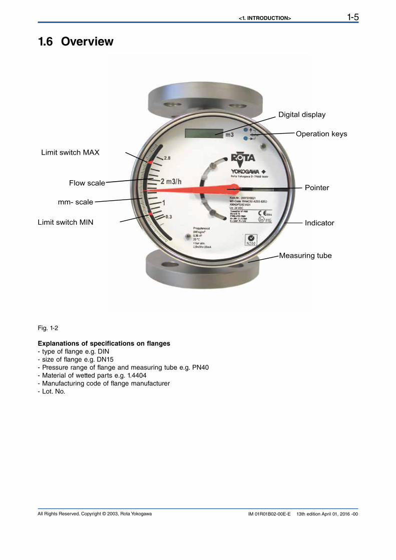
1.6 Overview
Fig. 1-2
Explanations of specifications on flanges
- type of flange e.g. DIN- size of flange e.g. DN15- Pressure range of flange and measuring tube e.g. PN40- Material of wetted parts e.g. 1.4404
- Manufacturing code of flange manufacturer- Lot. No.
Digital display
Operation keys
Pointer
Measuring tube
Indicator
Flow scale
Limit switch MIN
Limit switch MAX
mm- scale
<1. INTRODUCTION>1-6
All Rights Reserved. Copyright © 2003, Rota YokogawaIM 01R01B02-00E-E 13th edition April 01, 2016 -00
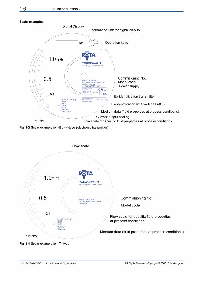
Scale examples
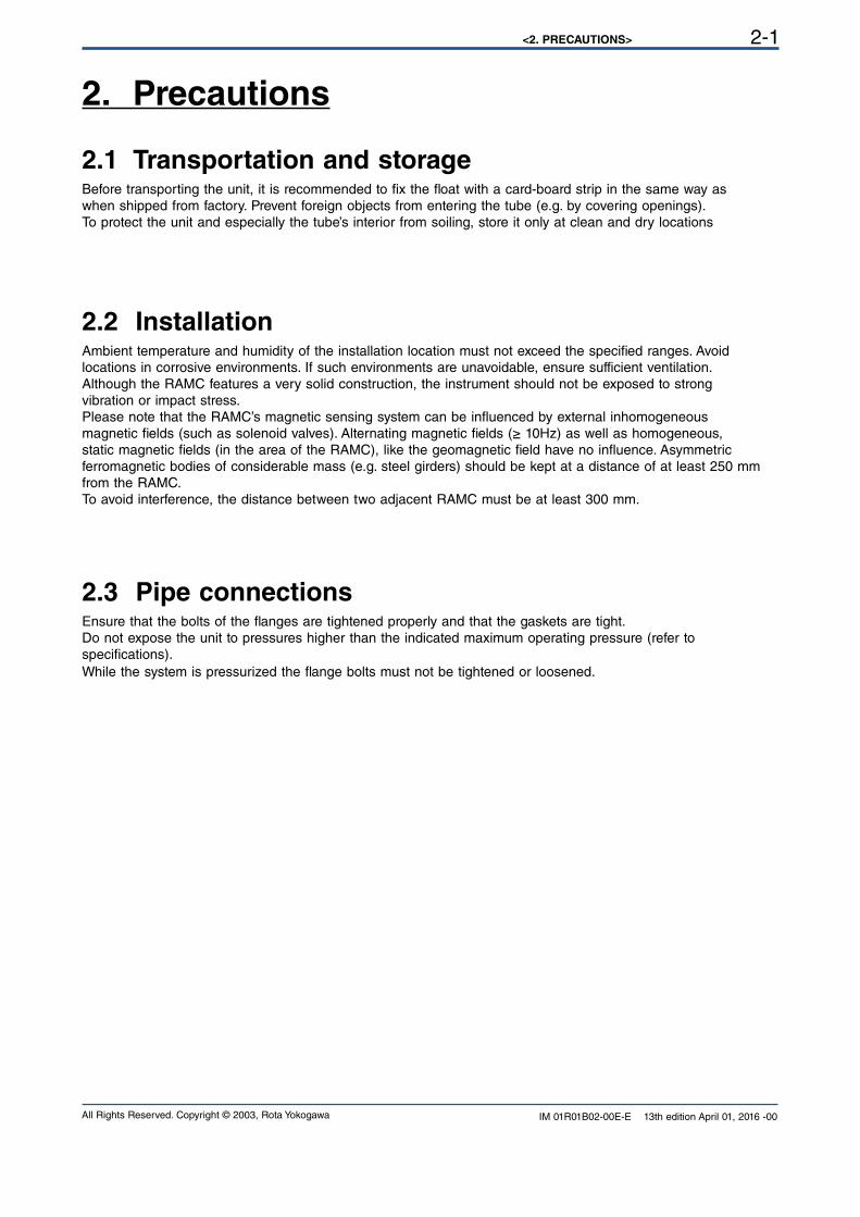
Fig. 1-4 Scale example for -T -type
Fig. 1-3 Scale example for -E / -H-type (electronic transmitter)
Tag No.: FIT...abcdefg
1.1 bar abs.1m3/h = 20mA
1 mPas20 Grad C
Liquide1.1 t/m3
E90244*D/B0/CP/K3MS-Code: RAMC01-D4SS-43S0-
UN: 230VAC 50/60Hz 8VA
Kom.Nr.: 200000/001
Rota Yokogawa D-79660 Wehr
Transmitter WT-MAG
PTB96 ATEX 2160X
Ci = 4,16nF Ii = 101mA
PTB99 ATEX 2219Xsee certificate for data
Limit Switch SC3,5-N0
Ui = 30V Li = 0,15mH Pi = 1,4W
EEx ia IIC T6
EEx ia IIC T6
II2G
0344
II2G
Enter
F11.EPS
0.1
0.5
m /h1.0 3
3m
Digital DisplayEngineering unit for digital display
Operation keys
Commisioning No.Model code
Power supply
Ex-identification transmitter
Ex-identification limit switches (/K_)
Current output scaling
Medium data (fluid properties at process conditions)
Flow scale for specific fluid properties at process conditions
Tag No.: FIT...abcdefg
1.1 bar abs.
1 mPas20 Grad C
Liquide1.1 t/m3
T90NNN*DMS-Code: RAMC01-D4SS-43S0-Kom.Nr.: 200000/001
Rota Yokogawa D-79660 Wehr
0.1
0.5
m /h1.0 3
F12.EPS
Flow scale
Commissioning No.
Model code
Medium data (fluid properties at process conditions)
Flow scale for specific fluid properties
at process conditions
<2. PRECAUTIONS> 2-1
All Rights Reserved. Copyright © 2003, Rota Yokogawa IM 01R01B02-00E-E 13th edition April 01, 2016 -00
2. Precautions
2.1 Transportation and storageBefore transporting the unit, it is recommended to fix the float with a card-board strip in the same way aswhen shipped from factory. Prevent foreign objects from entering the tube (e.g. by covering openings).To protect the unit and especially the tube’s interior from soiling, store it only at clean and dry locations
2.2 InstallationAmbient temperature and humidity of the installation location must not exceed the specified ranges. Avoidlocations in corrosive environments. If such environments are unavoidable, ensure sufficient ventilation.
Although the RAMC features a very solid construction, the instrument should not be exposed to strongvibration or impact stress.
Please note that the RAMC’s magnetic sensing system can be influenced by external inhomogeneousmagnetic fields (such as solenoid valves). Alternating magnetic fields (≥ 10Hz) as well as homogeneous,
static magnetic fields (in the area of the RAMC), like the geomagnetic field have no influence. Asymmetric ferromagnetic bodies of considerable mass (e.g. steel girders) should be kept at a distance of at least 250 mmfrom the RAMC.
To avoid interference, the distance between two adjacent RAMC must be at least 300 mm.
2.3 Pipe connectionsEnsure that the bolts of the flanges are tightened properly and that the gaskets are tight.Do not expose the unit to pressures higher than the indicated maximum operating pressure (refer tospecifications).
While the system is pressurized the flange bolts must not be tightened or loosened.

<2. PRECAUTIONS>2-2
All Rights Reserved. Copyright © 2003, Rota YokogawaIM 01R01B02-00E-E 13th edition April 01, 2016 -00
Blank Page
<3. INSTALLATION> 3-1
All Rights Reserved. Copyright © 2003, Rota Yokogawa IM 01R01B02-00E-E 13th edition April 01, 2016 -00
3. Installation
3.1 Installation in the pipelineBe sure to remove the transport lock card-board strip from the measuring tube. Check that no cardboard
remains in the tube.
The RAMC flow rate meter must be installed in a vertical pipeline, in which the medium flows upwards. The vertical position has to be checked at the outer edge of the flanges. Bigger nominal diameters (DN80/DN100)require straight pipe sections of at least 5D in front and behind the RAMC.The nominal diameter of the RAMC should correspond to the nominal diameter of the pipeline.To avoid stress in the connecting pipes, the connecting flanges must be aligned in parallel and axial direction.Bolts and gaskets have to be selected according to the maximum operating pressure, the temperature rangeand corrosion conditions. Centre gaskets and tighten nuts with a torque appropriate for the pressure range.
If contamination or soiling of the RAMC is to be expected, a bypass should be installed to allow the removal of the instrument without interruption of the flow.Please read also chapter 2.2. For further instructions on installation please refer to VDI/VDE3513.
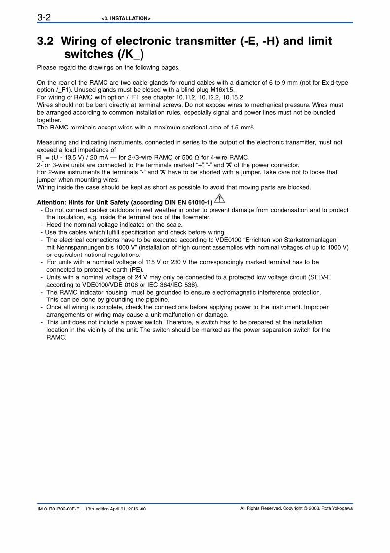
Tightening the flange threads for RAMC with PTFE- liner with the following torques:Nominal Size Bolts Maximum Torque
EN 1092-1 ASME B 16.5 EN 1092-1 ASME EN 1092-1 ASME 150 lbs
DN PN Inches lbs 150 lbs 300 lbs Nm ft*lbf Nm ft*lbf
15 40 ½ 150/300 4 x M12 4 x ½´´ 4 x ½´´ 9.8 7.1 5.2 3.8
25 40 1 150/300 4 x M12 4 x ½´´ 4 x ½´´ 21 15 10 7.2
50 40 2 150/300 4 x M16 4 x 5/8´´ 8 x 5/8´´ 57 41 41 30
80 16 3 150/300 4 x M16 4 x 5/8´´ 8 x ¾´´ 47 34 70 51100 16 4 150/300 4 x M16 8 x 5/8´´ 8 x ¾´´ 67 48 50 36
<3. INSTALLATION>3-2
All Rights Reserved. Copyright © 2003, Rota YokogawaIM 01R01B02-00E-E 13th edition April 01, 2016 -00
3.2 Wiring of electronic transmitter (-E, -H) and limit switches (/K_)
Please regard the drawings on the following pages.
On the rear of the RAMC are two cable glands for round cables with a diameter of 6 to 9 mm (not for Ex-d-type option /_F1). Unused glands must be closed with a blind plug M16x1.5. For wiring of RAMC with option /_F1 see chapter 10.11.2, 10.12.2, 10.15.2. Wires should not be bent directly at terminal screws. Do not expose wires to mechanical pressure. Wires must be arranged according to common installation rules, especially signal and power lines must not be bundled
together.
The RAMC terminals accept wires with a maximum sectional area of 1.5 mm2.
Measuring and indicating instruments, connected in series to the output of the electronic transmitter, must not
exceed a load impedance of RL = (U - 13.5 V) / 20 mA — for 2-/3-wire RAMC or 500 Ω for 4-wire RAMC.2- or 3-wire units are connected to the terminals marked “+”, “-” and “A” of the power connector.
For 2-wire instruments the terminals “-” and “A” have to be shorted with a jumper. Take care not to loose thatjumper when mounting wires.Wiring inside the case should be kept as short as possible to avoid that moving parts are blocked.
Attention: Hints for Unit Safety (according DIN EN 61010-1)
- Do not connect cables outdoors in wet weather in order to prevent damage from condensation and to protect
the insulation, e.g. inside the terminal box of the flowmeter.- Heed the nominal voltage indicated on the scale.
- Use the cables which fulfill specification and check before wiring.- The electrical connections have to be executed according to VDE0100 “Errichten von Starkstromanlagen mit Nennspannungen bis 1000 V” (Installation of high current assemblies with nominal voltages of up to 1000 V) or equivalent national regulations.
- For units with a nominal voltage of 115 V or 230 V the correspondingly marked terminal has to be connected to protective earth (PE).- Units with a nominal voltage of 24 V may only be connected to a protected low voltage circuit (SELV-E according to VDE0100/VDE 0106 or IEC 364/IEC 536). - The RAMC indicator housing must be grounded to ensure electromagnetic interference protection. This can be done by grounding the pipeline.- Once all wiring is complete, check the connections before applying power to the instrument. Improper
arrangements or wiring may cause a unit malfunction or damage.
- This unit does not include a power switch. Therefore, a switch has to be prepared at the installation location in the vicinity of the unit. The switch should be marked as the power separation switch for the RAMC.
<3. INSTALLATION> 3-3
All Rights Reserved. Copyright © 2003, Rota Yokogawa IM 01R01B02-00E-E 13th edition April 01, 2016 -00
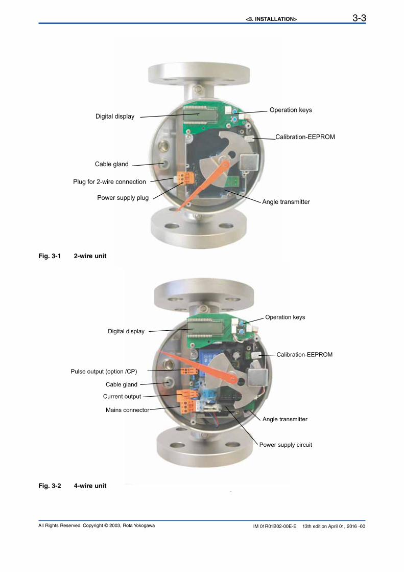
Fig. 3-2 4-wire unit
Operation keys
Calibration-EEPROM
Angle transmitter
Power supply circuit
Digital display
Pulse output (option /CP)
Current output
Mains connector
Cable gland
Operation keys
Calibration-EEPROM
Angle transmitter
Digital display
Cable gland
Power supply plug
Plug for 2-wire connection
Fig. 3-1 2-wire unit
<3. INSTALLATION>3-4
All Rights Reserved. Copyright © 2003, Rota YokogawaIM 01R01B02-00E-E 13th edition April 01, 2016 -00
15
4
6
3
1
14
12
1011
87
9U
F
G
RAMC
A Power supply U
Mains 230V AC
KFA6-SR2-Ex2.W
Option: /W2BTransmitter Relay
Limit MIN
Limit MAX
Option / Kn
Rotameter
4-20mA
Max
Min
12
11
109
Limit switches
EN 60947-5-6 (Namur)
One channel connection like limit MAX
4-20mA
RL
-
+
-
+
-
+
-
+
~ ~
+-
+-
Power supply U / V RL / W
13.5V ... 30V < (U-13.5V) / 20mA
F1.EPS
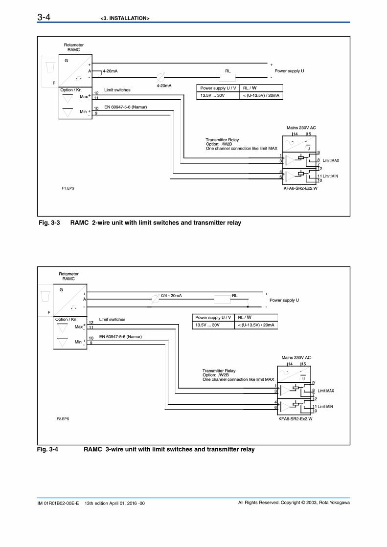
Fig. 3-3 RAMC 2-wire unit with limit switches and transmitter relay
15
4
6
3
1
14
12
1011
87
9U
F
G
RAMC
A Power supply U
Mains 230V AC
KFA6-SR2-Ex2.W
Option: /W2BTransmitter Relay
Limit MIN
Limit MAX
Option / Kn
Rotameter
Max
Min
12
11
109
Limit switches
EN 60947-5-6 (Namur)
One channel connection like limit MAX
0/4 - 20mA RL
-
+
-
+
-
+
-
+
~ ~
+-
+-
Power supply U / V RL / W
13.5V ... 30V < (U-13.5V) / 20mA
F2.EPS
Fig. 3-4 RAMC 3-wire unit with limit switches and transmitter relay
<3. INSTALLATION> 3-5
All Rights Reserved. Copyright © 2003, Rota Yokogawa IM 01R01B02-00E-E 13th edition April 01, 2016 -00
F
G
RAMC
230 / 115 V AC
4
Power supply
Output 0/4-20mA
R < 500 ΩL
Rotameter
PE--
5
7
6
Pulse outputUmax = 30V ; Imax = 100mA
-
+
-
+
+
-
F3.EPS
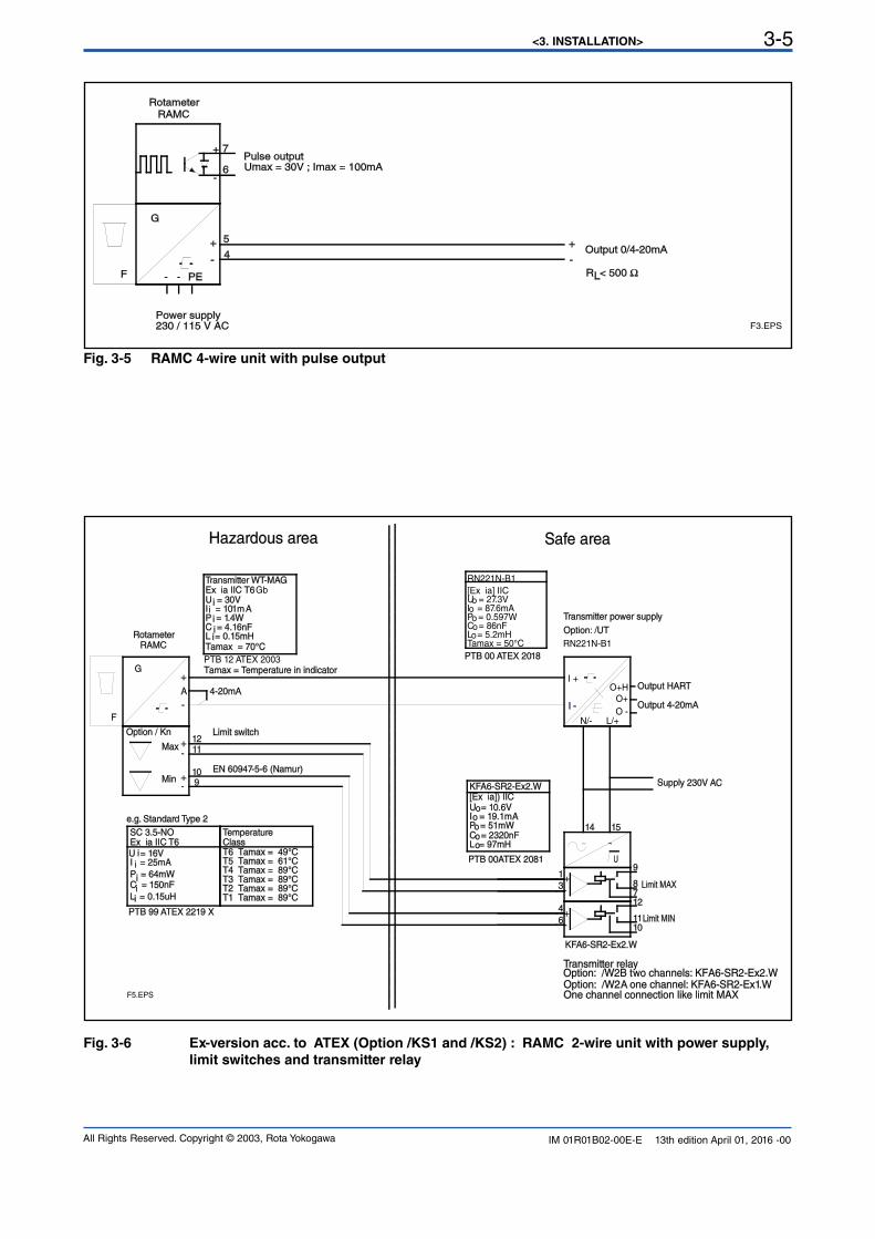
Fig. 3-5 RAMC 4-wire unit with pulse output
15
4
6
3
1
14
12
1011
87
9
1211
109
I -
I +
L/+N/-O -
O+Output 4-20mA
O+H Output HART
U
F
G
RAMC
A
Supply 230V AC
KFA6-SR2-Ex2.W
Option: /W2B two channels: KFA6-SR2-Ex2.WTransmitter relay
Limit MIN
Limit MAX
Option / Kn
Rotameter
4-20mA
Max
Min
Limit switch
EN 60947-5-6 (Namur)
One channel connection like limit MAX
I = 101mAP = 1.4WC = 4.16nF
U = 30V
L = 0.15mH
Transmitter WT-MAGEx ia IIC T6Gb
PTB 12 ATEX 2003
Tamax = 70°C
Tamax = Temperature in indicator
C = 150nF
Ex ia IIC T6
L = 0.15uH
SC 3.5-NO
P = 64mW
I = 25mAU = 16V
Temperature
T4 Tamax = 89°CT3 Tamax = 89°CT2 Tamax = 89°CT1 Tamax = 89°C
Class
T5 Tamax = 61°CT6 Tamax = 49°C
PTB 99 ATEX 2219 X
PTB 00 ATEX 2018
Transmitter power supply
Option: /UT
Option: /W2A one channel: KF A6-SR2-Ex1.W
C = 2320nF
I = 19.1mAP = 51mW
U = 10.6V
L = 97mH
PTB 00ATEX 2081
[Ex ia]) IICKFA6-SR2-Ex2.W
RN221N-B1
RN221N-B1
Tamax = 50°C
C = 86nFL = 5.2mH
U = 27.3V
P = 0.597W
[Ex ia] IIC
I = 87.6mAo
oo
oo
e.g. Standard Type 2
-
+
-
+
-
+
~ ~
+-
+-
i
ii
i
iii
i
i
o
oo
oo
F5.EPS
i
Hazardous area Safe area
Fig. 3-6 Ex-version acc. to ATEX (Option /KS1 and /KS2) : RAMC 2-wire unit with power supply,
limit switches and transmitter relay
<3. INSTALLATION>3-6
All Rights Reserved. Copyright © 2003, Rota YokogawaIM 01R01B02-00E-E 13th edition April 01, 2016 -00
15
4
6
3
1
14
12
1011
87
9U
F
G
RAMC
A Power supply U
Mains 230V AC
KFA6-SR2-Ex2.W
Option: /W2BTransmitter Relay
Limit MIN
Limit MAX
Option / Kn
Rotameter
4-20mA
Max
Min
12
11
109
Limit switches
EN 60947-5-6 (Namur)
One channel connection like limit MAX
4-20mA
RL
HART-Communication
with HART-Communication
without HART-Communication
Power supply U/V RL/Ω
13.5V+(RL*20mA) ...30V
13.5V ... 30V < (U-13.5V) / 20mA
250 ... 500 Ω
-
+
-
+
-
+
-
+
~ ~
+-
+-
F4.EPS
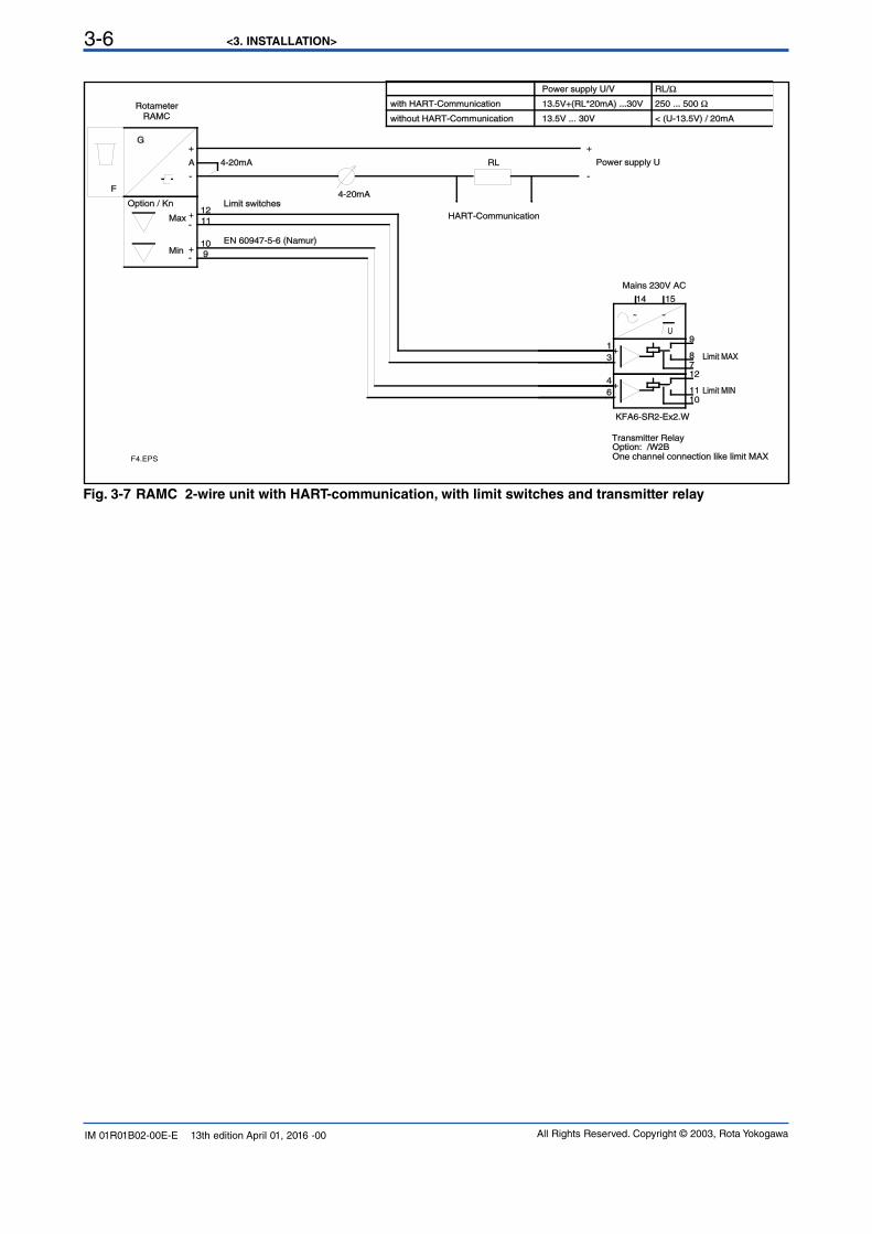
Fig. 3-7 RAMC 2-wire unit with HART-communication, with limit switches and transmitter relay
<4. START OF OPERATION> 4-1
All Rights Reserved. Copyright © 2003, Rota Yokogawa IM 01R01B02-00E-E 13th edition April 01, 2016 -00
4. Start of operation
4.1 Hints on flow rate measurementThe measured fluid should neither consist of a multi-phase mixture nor contain ferrite ingredients or large solid mass particles.
The RAMC scale is adjusted to the state of operation/aggregation of the measured fluid by the manufacturer. Ifthe state of operation changes, it might become necessary to establish a new scale. This depends on severalfactors:
- If the RAMC is operated in the given viscosity independent range, only the density of the float as well as the operational density of the previous and new substance have to be considered. In case the operational
density only changes marginally (≤ 0.5%), the present scale can be used.- If the RAMC is operated outside the given viscosity independent range, the viscosities at the previous and new
state of operation as well as the mass and diameter of the float have to be taken into account.
4.2 Pulsation and pressure shockPressure shock waves and pulsating flow influence measurement considerable or can destroy the meter. Surge conditions should be avoided. (open valves slowly, raise operating pressure slowly)
If float bouncing occurs in gases increase the line pressure until the phenomena stop. If this is not possible provide the float with a damper. A damping kit is available as spare part.
4.3 Start of operation of electronic transmitterEnsure that the device has been connected correctly according to section 3-2 and that the used power supply
meets the requirements indicated on the scale.
Switch on the power supply.The digital display gives the totalizer value in the measuring unit, indicated on the right side of the display.The RAMC is now ready for operation.
Unit graduation, measuring unit, damping, etc. can be adjusted by an operating menu (refer to section 6.2). Incase of an error, the bars beneath the 8 digits of the display will flash. The corresponding error message canbe checked using the operating menu and then taking the appropriate counter measures (refer to section
6-2-8 “Error Messages”).
The transmitter has been prepared and calibrated according to the model code as a 2-, 3- or 4-wire unit. In 2-wire units, a jumper connects “A” and “-”. When switching from a 2- to a 3-wire configuration, this jumpershould be removed. The current output should then be adjusted as explained in section 6-2-6.When changing from a 3- to 2-wire configuration, the jumper should be set in place, and the current outputhas to be adjusted according to section 6-2-6.
<4. START OF OPERATION>4-2
All Rights Reserved. Copyright © 2003, Rota YokogawaIM 01R01B02-00E-E 13th edition April 01, 2016 -00
Blank Page
<5. LIMIT SWITCHES OPTION /K[]> 5-1
All Rights Reserved. Copyright © 2003, Rota Yokogawa IM 01R01B02-00E-E 13th edition April 01, 2016 -00
The optional limit switches are available as maximum or minimum type switches. They are proximity switchesaccording to EN 60947-5-6 (NAMUR). Maximal two switches can be installed. The option (/Wnn) includes therespective transmitter relay.
These switches have been specified for hazardous area. However, the transmitter relay must be installedin safe area.
The limit switches are connected to the transmitter relays as indicated in chapter 3.2.The terminals for the limit switches are on a small board on top of the transmitter case.
Use of 2 standard limit switches (option /K3):
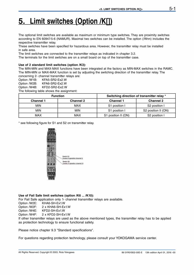
The MIN-MIN and MAX-MAX functions have been integrated at the factory as MIN-MAX switches in the RAMC. The MIN-MIN or MAX-MAX function is set by adjusting the switching direction of the transmitter relay. The concerning 2- channel transmitter relays are:
Option /W1B: KFA5-SR2-Ex2.W Option /W2B: KFA6-SR2-Ex2.WOption /W4B: KFD2-SR2-Ex2.WThe following table shows the assignment:
Function Switching direction of transmitter relay *
Channel 1 Channel 2 Channel 1 Channel 2
MIN MAX S1 position I S2 position I
MIN MIN S1 position I S2 position II (ON)
MAX MAX S1 position II (ON) S2 position I
* see following figure for S1 and S2 on transmitter relay.
Use of Fail Safe limit switches (option /K6 ... /K10):
For Fail Safe application only 1- channel transmitter relays are available.Option /W2E: KHA6-SH-Ex1.WOption /W2F: 2 x KHA6-SH-Ex1.WOption /W4E: KFD2-SH-Ex1.WOption /W4F: 2 x KFD2-SH-Ex1.WIf other transmitter relays are used as the above mentioned types, the transmitter relay has to be applied
as protection technology to ensure functional safety.
Please notice chapter 9.3 "Standard specifications".
For questions regarding protection technology, please consult your YOKOGAWA service center.
5. Limit switches (Option /K[])
<5. LIMIT SWITCHES OPTION /K[]>5-2
All Rights Reserved. Copyright © 2003, Rota YokogawaIM 01R01B02-00E-E 13th edition April 01, 2016 -00
Blank Page
<6. ELECTRONIC TRANSMITTER (-E)> 6-1
All Rights Reserved. Copyright © 2003, Rota Yokogawa IM 01R01B02-00E-E 13th edition April 01, 2016 -00
6. Electronic Transmitter (-E)
6.1 Operation principleThe position of the float is magnetically transferred to a magnetic follow up system. The position angle of thismagnetic rocker is detected by magnet sensors. A micro controller determines the angle by means of a
combining reference value table in the memory and calculates the flow rate by the angle with calibration andoperation parameters the calibration EEPROM. The flow rate is given as a current, either 0-20 mA or 4-20 mA,and, in addition, indicated on the digital display (refer also to section 6-2). The electronic transmitters have been electronically adjusted before shipping and, therefore, are mutually exchangeable.Calibration data of the metering tube as well as customer specific data are entered into a calibration EEPROM,inserted on the board. This calibration EEPROM and the indication scale are assigned to the respectivemetering tube.
When replacing an indicator (e.g. because of a defect) the scale and calibration EEPROM of the old unit haveto be inserted in the new unit. Then, no calibrations or adjustments are necessary.If an indicator with electronic transmitters is installed to a new metering tube, the calibration EEPROM of thattube has to be inserted into the transmitter and the indicator scale for that particular tube has to be mounted.
A change in the fluid data (e.g. specific gravity, pressure, etc.) requires the preparation and mounting of
a new calibration EEPROM and scale.
Normally the range of the current output is equal to the rounded measuring range of the tube (end value onscale). The customer can position the 20 mA point between 60% and 100% of the end value on scale. The setof the 20 mA point is shown on the scale (refer to Fig. 1-4). The flow cut off is positioned at 5% of the end value.Below 5% flow the current output shows 0 mA (4 mA).
6.2 Parameter settingThe displays allows indication of various parameters:• Flow rate (8 mass or volume units in combination with 4 time units)• Counter (8 mass or volume units)
• Flow rate indication in percent• Special functions:• Setting of different damping times• Switching of current output 0-20 mA / 4-20 mA or vice versa• Indication of error messages
• Manual adjustment• Service functions• Detection of float blockage
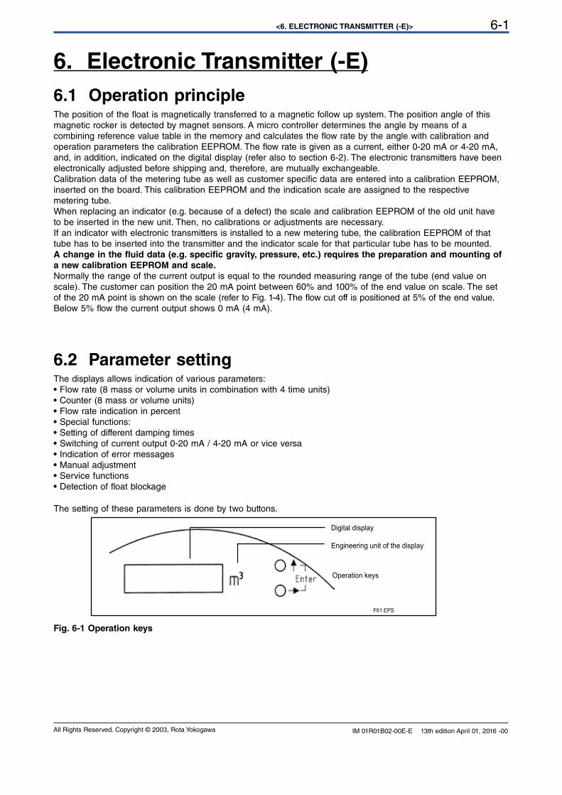
The setting of these parameters is done by two buttons.
Fig. 6-1 Operation keys
F61.EPS
Digital display
Engineering unit of the display
Operation keys
<6. ELECTRONIC TRANSMITTER (-E)>6-2
All Rights Reserved. Copyright © 2003, Rota YokogawaIM 01R01B02-00E-E 13th edition April 01, 2016 -00
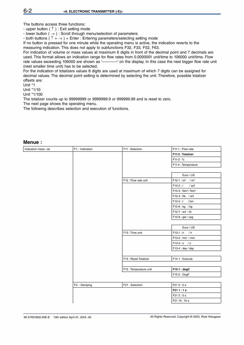
The buttons access three functions:- upper button ( ↑ ) : Exit setting mode- lower button ( → ) : Scroll through menu/selection of parameters- both buttons ( ↑ + → ) = Enter : Entering parameters/selecting setting mode
If no button is pressed for one minute while the operating menu is active, the indication reverts to the
measuring indication. This does not apply to subfunctions F32, F33, F52, F63.For indication of volume or mass values at maximum 6 digits in front of the decimal point and 7 decimals areused. This format allows an indication range for flow rates from 0.0000001 unit/time to 106000 unit/time. Flowrate values exceeding 106000 are shown as ‘————’ on the display. In this case the next bigger flow rate unit (next smaller time unit) has to be selected.For the indication of totalizers values 8 digits are used at maximum of which 7 digits can be assigned fordecimal values. The decimal point setting is determined by selecting the unit. Therefore, possible totalizeroffsets are:
Unit *1Unit *1/10Unit *1/100The totalizer counts up to 99999999 or 9999999.9 or 999999.99 and is reset to zero.The next page shows the operating menu.The following describes selection and execution of functions.
Menue :
Indication meas .val F1- : Indication F11 : Selection F11-1 : Flow rate
F11-2 : Totalizer
F11-3 : %
F11-4 : Temperature
Euro / US
F12 : Flow rate unit F12-1 : m³ / m³
F12-2 : l / acf
F12-3 : Nm³ / Nm³
F12-4 : NL / scf
F12-5 : t / ton
F12-6 : kg / kg
F12-7 : scf / lb
F12-8 : gal / usg
Euro / US
F13 : Time unit F13-1 : h / h
F13-2 : min / min
F13-3 : s / s
F13-4 : day / day
F14 : Reset Totalizer F14-1 : Execute
F15 : Temperature unit F15-1 : degC
F15-2 : DegF
F2- : Damping F21 : Selection F21 0 : 0 s
F21 1 : 1 s
F21 5 : 5 s
F21 10 : 10 s
<6. ELECTRONIC TRANSMITTER (-E)> 6-3
All Rights Reserved. Copyright © 2003, Rota Yokogawa IM 01R01B02-00E-E 13th edition April 01, 2016 -00
F3- : Output F31 : Selection F31 0-20 : 0-20 mA
F31 4-20 : 4-20 mA
F32 : Offset adjustment F32 00
F33 : Span adjustment F33 00
F34 : Pulse output *) F34-1 : not active
F34-2 : last digit
F34-3 : last but one digit
F4- : Error messages F41 : Indication F41 Enn
F5- : Manual calibr. F51 : On/Off F51-1 : off
F51-2 : on
F52 : Calibration table F52 5 : 5% point
F52 15 : 15% point
F52 25 : 25% point
F52 35 : 35 point
F52 45 : 45% point
F52 55 : 55% point
F52 65 : 65% point
F52 75 : 75% point
F52 85 : 85% point
F52 95 : 95% point
F52 105 : 105% point
F6- : Service F61 : Revision indicatior H.. F..
F62 : EEPROM revision A.. C..
F63 : Current output test F63 04 : 0 or 4 mA
F63 20 : 20 mA
F64 : Calibration table F64-1 : Standard
F64-2 : Remote version
F65 : Master Reset F65-1 : Execute
F7- : Float Block. Ind. F71 : Off/On F71-1 : Off/On
F71-2 : On/Off
F72 : Lower limit F72-1 : 5% of Qmax
F72-2 : 15% of Qmax
F72-3 : 30% of Qmax
F73 : Supervision time F73-1 : 5 Minutes
F73-2 : 15 Minutes
F74 : Autozero F74-1 : Execute
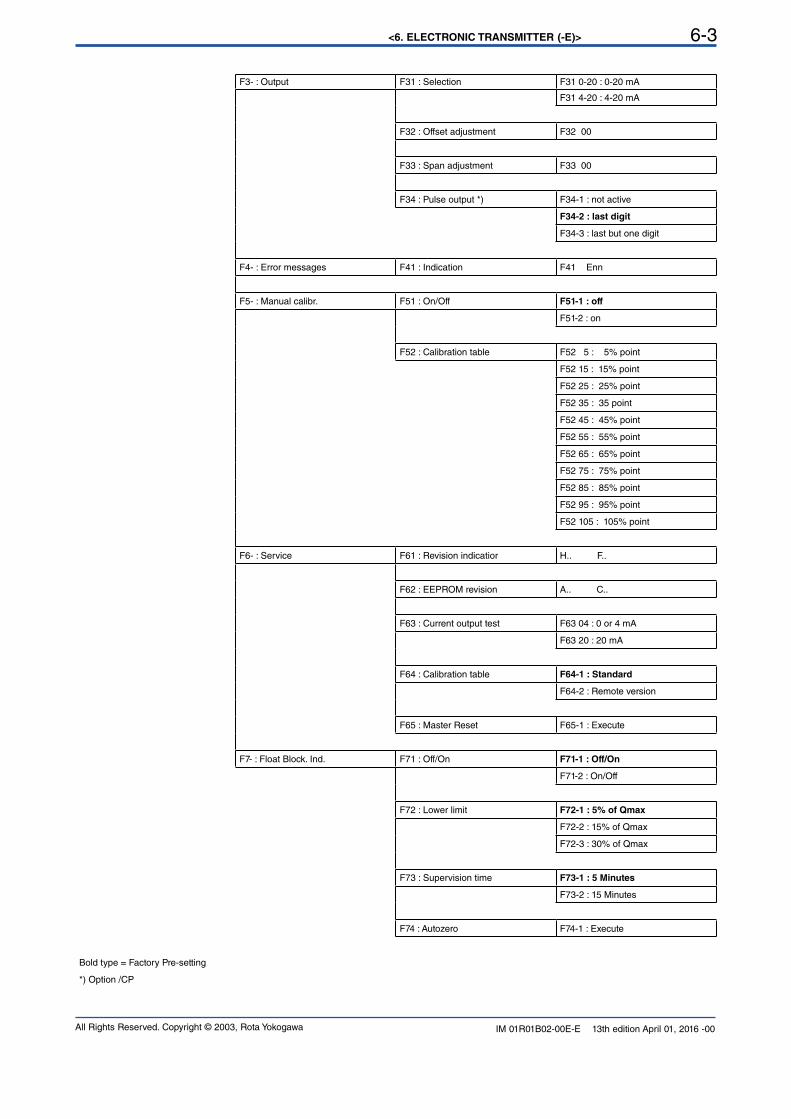
Bold type = Factory Pre-setting
*) Option /CP
<6. ELECTRONIC TRANSMITTER (-E)>6-4
All Rights Reserved. Copyright © 2003, Rota YokogawaIM 01R01B02-00E-E 13th edition April 01, 2016 -00
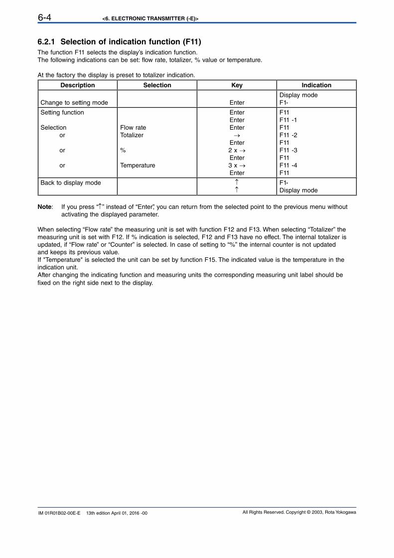
6.2.1 Selection of indication function (F11)
The function F11 selects the display’s indication function.The following indications can be set: flow rate, totalizer, % value or temperature.
At the factory the display is preset to totalizer indication.
Description Selection Key Indication
Change to setting mode Enter
Display mode
F1-
Setting function
Selection or
or
or
Flow rateTotalizer
%
Temperature
Enter
Enter
Enter
→Enter
2 x →Enter
3 x →Enter
F11F11 -1F11F11 -2F11F11 -3F11F11 -4F11
Back to display mode ↑↑
F1-Display mode
Note: If you press “↑” instead of “Enter”, you can return from the selected point to the previous menu without
activating the displayed parameter.
When selecting “Flow rate” the measuring unit is set with function F12 and F13. When selecting “Totalizer” themeasuring unit is set with F12. If % indication is selected, F12 and F13 have no effect. The internal totalizer isupdated, if “Flow rate” or “Counter” is selected. In case of setting to “%” the internal counter is not updatedand keeps its previous value.
If "Temperature" is selected the unit can be set by function F15. The indicated value is the temperature in theindication unit.
After changing the indicating function and measuring units the corresponding measuring unit label should be
fixed on the right side next to the display.
<6. ELECTRONIC TRANSMITTER (-E)> 6-5
All Rights Reserved. Copyright © 2003, Rota Yokogawa IM 01R01B02-00E-E 13th edition April 01, 2016 -00
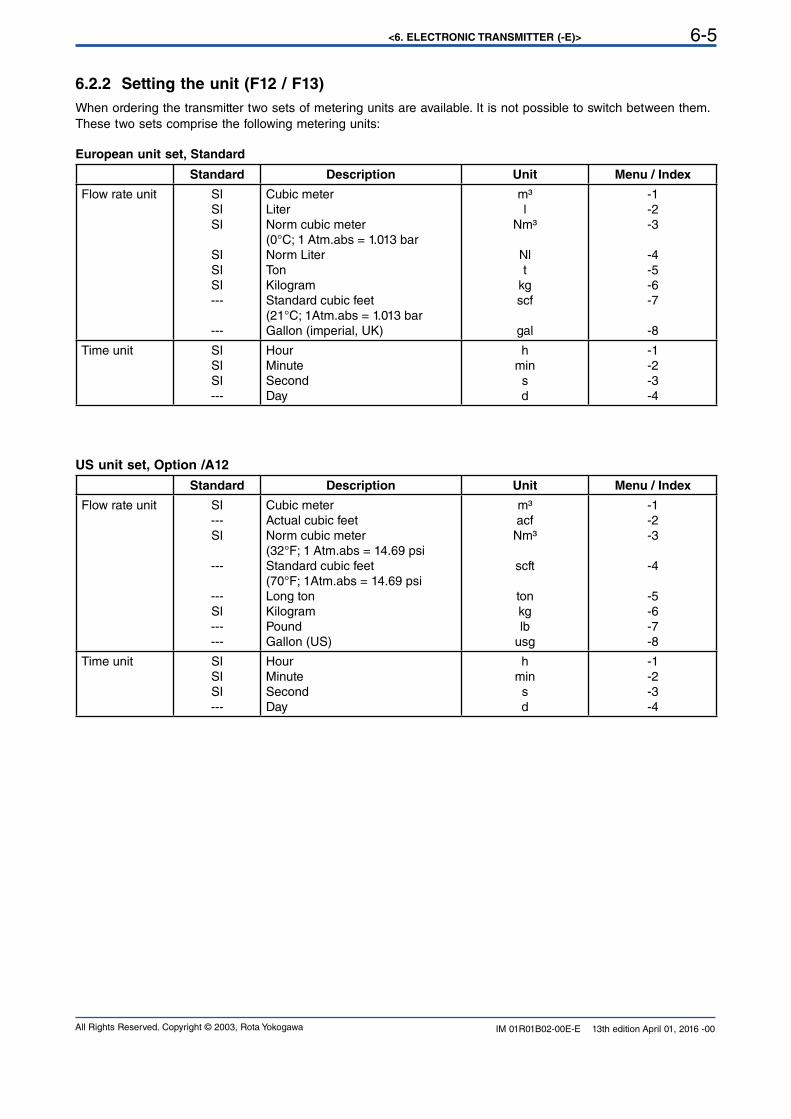
6.2.2 Setting the unit (F12 / F13)
When ordering the transmitter two sets of metering units are available. It is not possible to switch between them.
These two sets comprise the following metering units:
European unit set, Standard
Standard Description Unit Menu / Index
Flow rate unit SISISI
SISISI---
---
Cubic meter
LiterNorm cubic meter(0°C; 1 Atm.abs = 1.013 barNorm LiterTonKilogram
Standard cubic feet(21°C; 1Atm.abs = 1.013 barGallon (imperial, UK)
m³l
Nm³
Nlt
kg
scf
gal
-1
-2
-3
-4
-5-6
-7
-8
Time unit SISISI---
Hour
Minute
SecondDay
h
min
s
d
-1
-2
-3
-4
US unit set, Option /A12
Standard Description Unit Menu / Index
Flow rate unit SI---
SI
---
---
SI---
---
Cubic meter
Actual cubic feet
Norm cubic meter(32°F; 1 Atm.abs = 14.69 psiStandard cubic feet(70°F; 1Atm.abs = 14.69 psiLong tonKilogram
PoundGallon (US)
m³acf
Nm³
scft
ton
kg
lb
usg
-1
-2
-3
-4
-5-6
-7
-8
Time unit SISISI---
Hour
Minute
SecondDay
h
min
s
d
-1
-2
-3
-4
<6. ELECTRONIC TRANSMITTER (-E)>6-6
All Rights Reserved. Copyright © 2003, Rota YokogawaIM 01R01B02-00E-E 13th edition April 01, 2016 -00
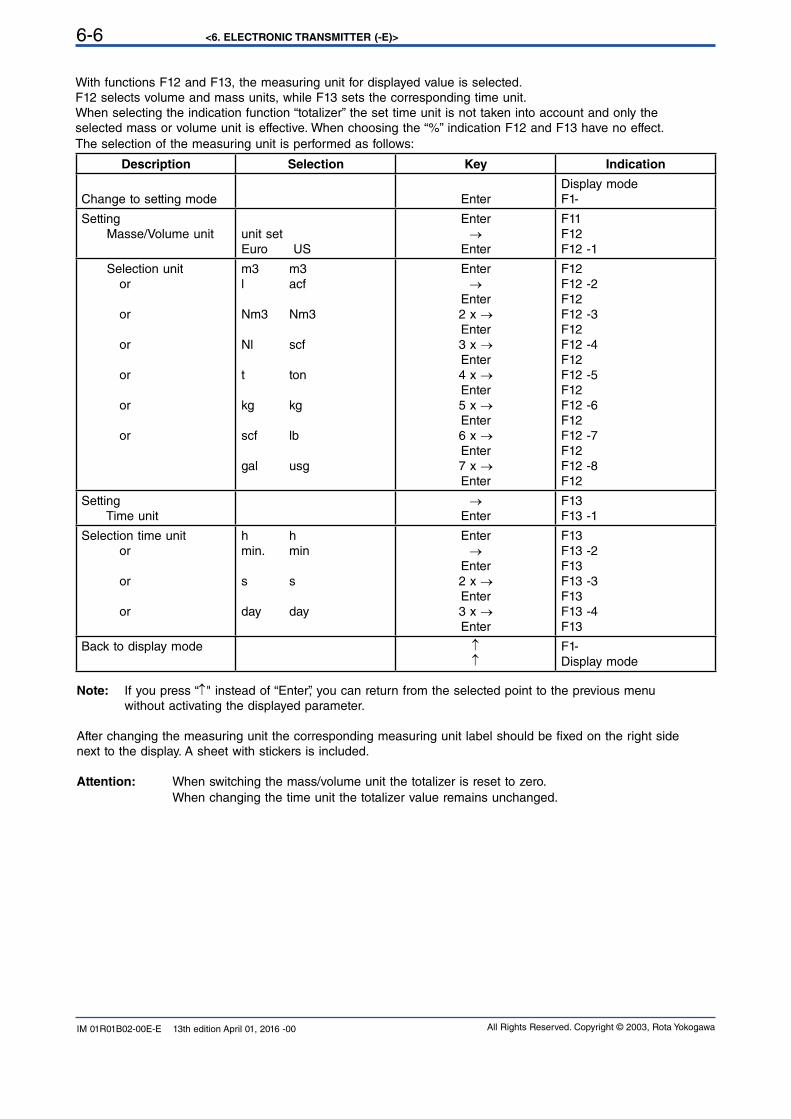
With functions F12 and F13, the measuring unit for displayed value is selected.F12 selects volume and mass units, while F13 sets the corresponding time unit.When selecting the indication function “totalizer” the set time unit is not taken into account and only the
selected mass or volume unit is effective. When choosing the “%” indication F12 and F13 have no effect.The selection of the measuring unit is performed as follows:
Description Selection Key Indication
Change to setting mode Enter
Display mode
F1-
Setting Masse/Volume unit unit set
Euro US
Enter
→Enter
F11F12F12 -1
Selection unit or
or
or
or
or
or
m3 m3
l acf
Nm3 Nm3
Nl scf
t ton
kg kg
scf lb
gal usg
Enter
→Enter
2 x →Enter
3 x →Enter
4 x →Enter
5 x →Enter
6 x →Enter
7 x →Enter
F12F12 -2F12F12 -3F12F12 -4F12F12 -5F12F12 -6F12F12 -7F12F12 -8F12
Setting Time unit
→Enter
F13F13 -1
Selection time unit or
or
or
h h
min. min
s s
day day
Enter
→Enter
2 x →Enter
3 x →Enter
F13F13 -2F13F13 -3F13F13 -4F13
Back to display mode ↑↑
F1-Display mode
Note: If you press “↑" instead of “Enter”, you can return from the selected point to the previous menu
without activating the displayed parameter.
After changing the measuring unit the corresponding measuring unit label should be fixed on the right sidenext to the display. A sheet with stickers is included.
Attention: When switching the mass/volume unit the totalizer is reset to zero.
When changing the time unit the totalizer value remains unchanged.
<6. ELECTRONIC TRANSMITTER (-E)> 6-7
All Rights Reserved. Copyright © 2003, Rota Yokogawa IM 01R01B02-00E-E 13th edition April 01, 2016 -00
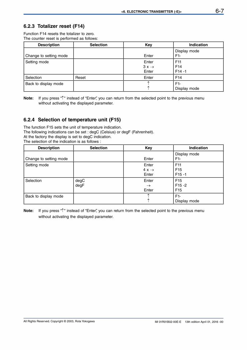
6.2.4 Selection of temperature unit (F15)
The function F15 sets the unit of temperature indication.The following indications can be set : degC (Celsius) or degF (Fahrenheit).At the factory the display is set to degC indication.
The selection of the indication is as follows :
Description Selection Key Indication
Change to setting mode Enter
Display mode
F1-
Setting mode Enter
4 x →Enter
F11F15F15 -1
Selection degC
degFEnter
→Enter
F15F15 -2F15
Back to display mode ↑↑
F1-Display mode
Note: If you press “↑" instead of “Enter”, you can return from the selected point to the previous menu
without activating the displayed parameter.
6.2.3 Totalizer reset (F14)
Function F14 resets the totalizer to zero.The counter reset is performed as follows:
Description Selection Key Indication
Change to setting mode Enter
Display mode
F1-
Setting mode Enter
3 x →Enter
F11F14F14 -1
Selection Reset Enter F14
Back to display mode ↑↑
F1-Display mode
Note: If you press “↑" instead of “Enter”, you can return from the selected point to the previous menu
without activating the displayed parameter.
<6. ELECTRONIC TRANSMITTER (-E)>6-8
All Rights Reserved. Copyright © 2003, Rota YokogawaIM 01R01B02-00E-E 13th edition April 01, 2016 -00
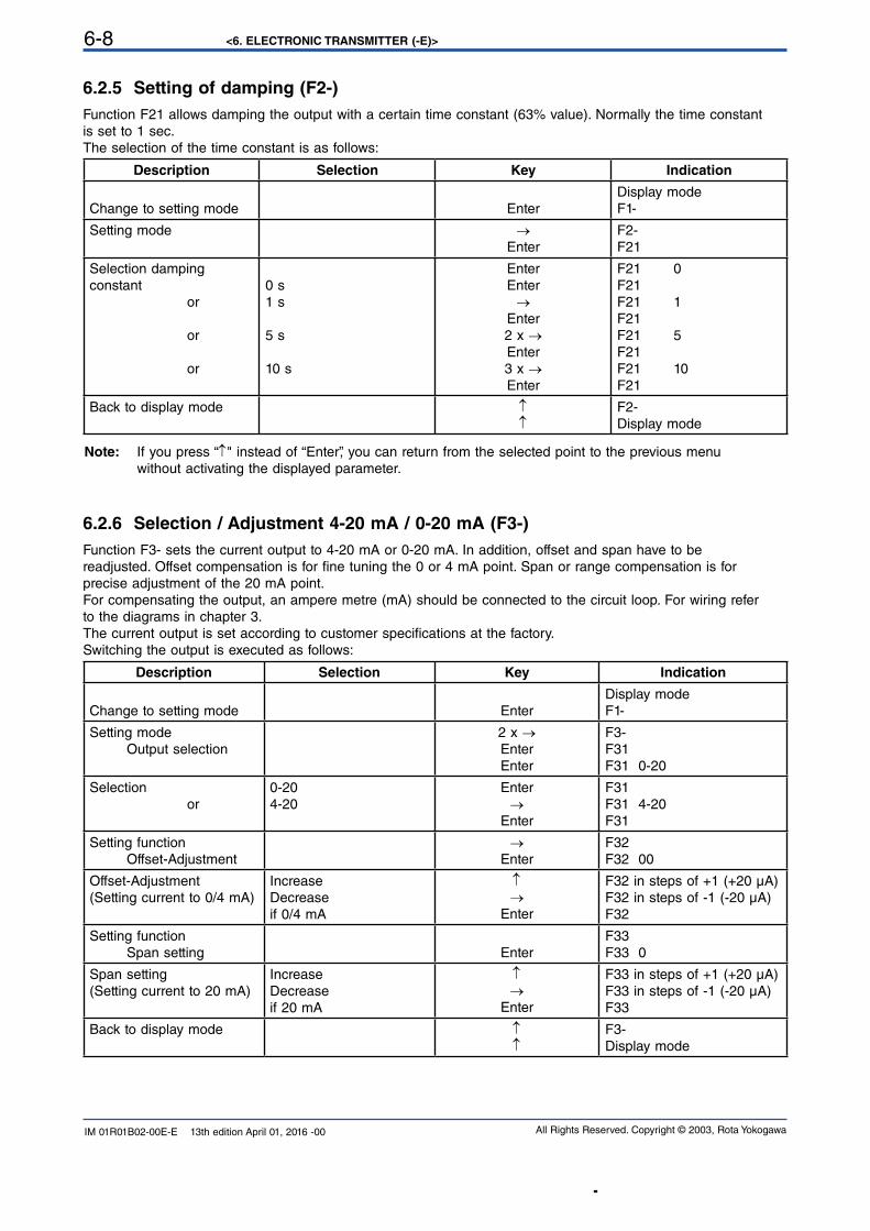
6.2.5 Setting of damping (F2-)
Function F21 allows damping the output with a certain time constant (63% value). Normally the time constantis set to 1 sec.
The selection of the time constant is as follows:
Description Selection Key Indication
Change to setting mode Enter
Display mode
F1-
Setting mode →Enter
F2-F21
Selection damping constant
or
or
or
0 s
1 s
5 s
10 s
Enter
Enter
→Enter
2 x →Enter
3 x →Enter
F21 0F21F21 1F21F21 5F21F21 10F21
Back to display mode ↑↑
F2-Display mode
Note: If you press “↑" instead of “Enter”, you can return from the selected point to the previous menu
without activating the displayed parameter.
6.2.6 Selection / Adjustment 4-20 mA / 0-20 mA (F3-)
Function F3- sets the current output to 4-20 mA or 0-20 mA. In addition, offset and span have to bereadjusted. Offset compensation is for fine tuning the 0 or 4 mA point. Span or range compensation is forprecise adjustment of the 20 mA point.For compensating the output, an ampere metre (mA) should be connected to the circuit loop. For wiring referto the diagrams in chapter 3.
The current output is set according to customer specifications at the factory.Switching the output is executed as follows:
Description Selection Key Indication
Change to setting mode Enter
Display mode
F1-
Setting mode Output selection
2 x →Enter
Enter
F3-F31F31 0-20
Selection or
0-20
4-20
Enter
→Enter
F31F31 4-20F31
Setting function Offset-Adjustment
→Enter
F32F32 00
Offset-Adjustment(Setting current to 0/4 mA)
Increase
Decrease
if 0/4 mA
↑→
Enter
F32 in steps of +1 (+20 µA)F32 in steps of -1 (-20 µA)F32
Setting function Span setting Enter
F33F33 0
Span setting(Setting current to 20 mA)
Increase
Decrease
if 20 mA
↑→
Enter
F33 in steps of +1 (+20 µA)F33 in steps of -1 (-20 µA)F33
Back to display mode ↑↑
F3-Display mode
<6. ELECTRONIC TRANSMITTER (-E)> 6-9
All Rights Reserved. Copyright © 2003, Rota Yokogawa IM 01R01B02-00E-E 13th edition April 01, 2016 -00
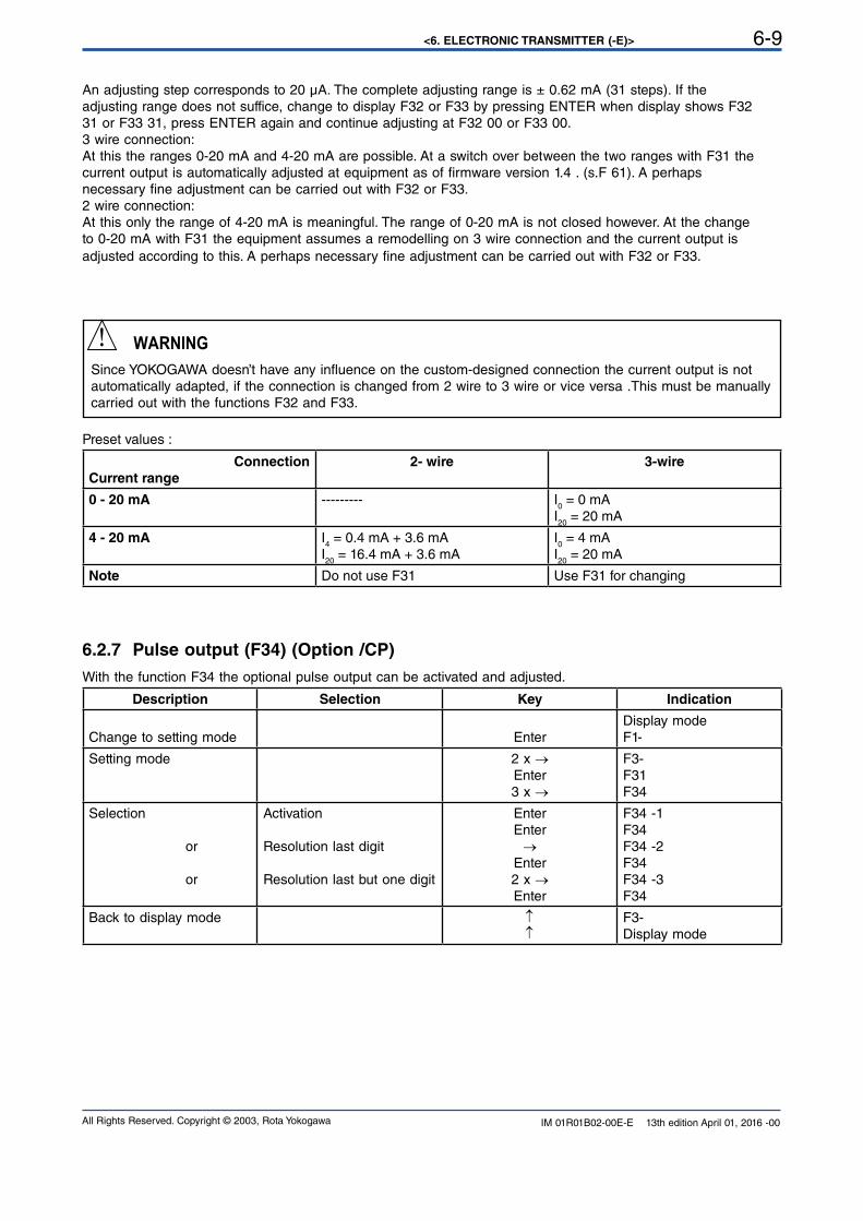
An adjusting step corresponds to 20 µA. The complete adjusting range is ± 0.62 mA (31 steps). If theadjusting range does not suffice, change to display F32 or F33 by pressing ENTER when display shows F3231 or F33 31, press ENTER again and continue adjusting at F32 00 or F33 00.3 wire connection:
At this the ranges 0-20 mA and 4-20 mA are possible. At a switch over between the two ranges with F31 thecurrent output is automatically adjusted at equipment as of firmware version 1.4 . (s.F 61). A perhapsnecessary fine adjustment can be carried out with F32 or F33.2 wire connection:
At this only the range of 4-20 mA is meaningful. The range of 0-20 mA is not closed however. At the changeto 0-20 mA with F31 the equipment assumes a remodelling on 3 wire connection and the current output isadjusted according to this. A perhaps necessary fine adjustment can be carried out with F32 or F33.
WARNING
Since YOKOGAWA doesn’t have any influence on the custom-designed connection the current output is not automatically adapted, if the connection is changed from 2 wire to 3 wire or vice versa .This must be manually carried out with the functions F32 and F33.
Preset values :
Connection
Current range
2- wire 3-wire
0 - 20 mA --------- I0 = 0 mA
I20
= 20 mA
4 - 20 mA I4 = 0.4 mA + 3.6 mA
I20
= 16.4 mA + 3.6 mA
I0 = 4 mA
I20
= 20 mA
Note Do not use F31 Use F31 for changing
6.2.7 Pulse output (F34) (Option /CP)
With the function F34 the optional pulse output can be activated and adjusted.
Description Selection Key Indication
Change to setting mode Enter
Display mode
F1-
Setting mode 2 x →Enter
3 x →
F3-F31F34
Selection
or
or
Activation
Resolution last digit
Resolution last but one digit
Enter
Enter
→Enter
2 x →Enter
F34 -1F34F34 -2F34F34 -3F34
Back to display mode ↑↑
F3-Display mode
<6. ELECTRONIC TRANSMITTER (-E)>6-10
All Rights Reserved. Copyright © 2003, Rota YokogawaIM 01R01B02-00E-E 13th edition April 01, 2016 -00
6.2.7.1 General
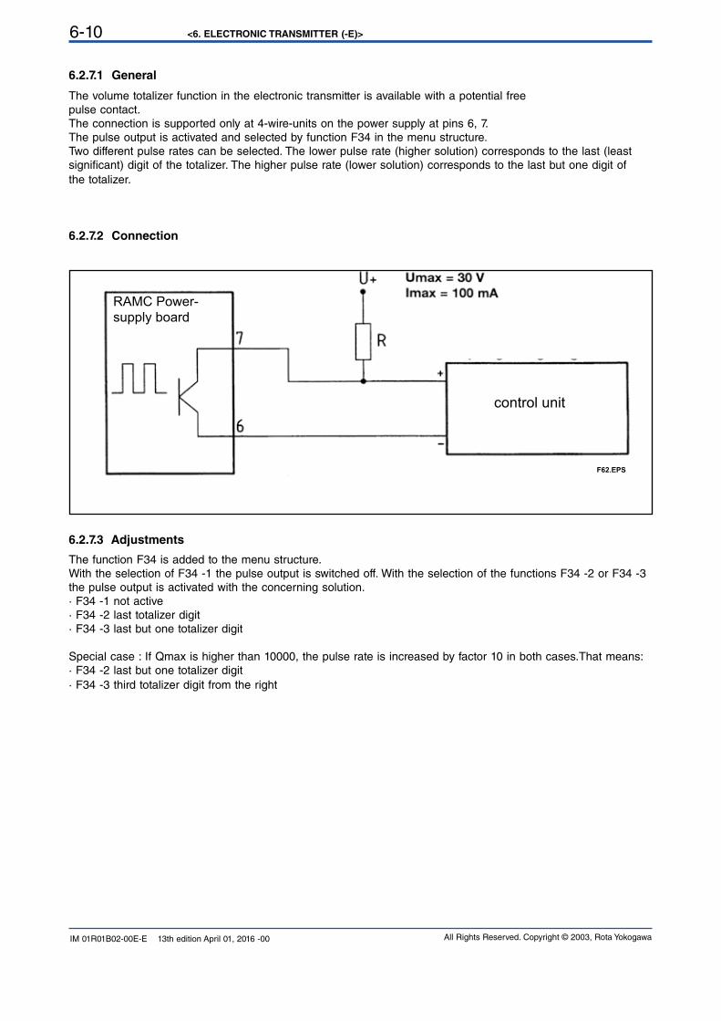
The volume totalizer function in the electronic transmitter is available with a potential freepulse contact.
The connection is supported only at 4-wire-units on the power supply at pins 6, 7.The pulse output is activated and selected by function F34 in the menu structure.Two different pulse rates can be selected. The lower pulse rate (higher solution) corresponds to the last (leastsignificant) digit of the totalizer. The higher pulse rate (lower solution) corresponds to the last but one digit ofthe totalizer.
6.2.7.2 Connection
6.2.7.3 Adjustments
The function F34 is added to the menu structure.With the selection of F34 -1 the pulse output is switched off. With the selection of the functions F34 -2 or F34 -3 the pulse output is activated with the concerning solution.
· F34 -1 not active· F34 -2 last totalizer digit· F34 -3 last but one totalizer digit
Special case : If Qmax is higher than 10000, the pulse rate is increased by factor 10 in both cases.That means:· F34 -2 last but one totalizer digit· F34 -3 third totalizer digit from the right
F62.EPS
RAMC Power-
supply board
control unit
<6. ELECTRONIC TRANSMITTER (-E)> 6-11
All Rights Reserved. Copyright © 2003, Rota Yokogawa IM 01R01B02-00E-E 13th edition April 01, 2016 -00
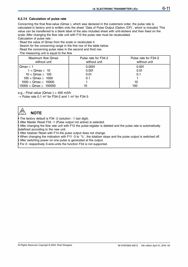
6.2.7.4 Calculation of pulse rate
Concerning the final flow-value (Qmax ), which was declared in the customers order, the pulse rate iscalculated in factory and is written onto the sheet ´Data of Pulse Output (Option /CP)´, which is included. Thisvalue can be transferred to a blank label of the also included sheet with unit-stickers and then fixed on thescale. After changing the flow rate unit with F12 the pulse rate must be recalculated.Calculation of pulse rate :
· Read the value of Qmax from the scale or recalculate it.· Search for the concerning range in the first row of the table below.· Read the concerning pulse rates in the second and third row.
· The measuring unit is equal to the flow
Maximum flow Qmaxwithout unit
Pulse rate for F34-2without unit
Pulse rate for F34-3without unit
Qmax ≤ 1
1 < Qmax ≤ 10
10 < Qmax ≤ 100
100 < Qmax ≤ 1000
1000 < Qmax ≤ 10000
10000 < Qmax ≤ 100000
0.0001
0.001
0.01
0.1
1
10
0.001
0.01
0.1
1
10
100
e.g..: Final value (Qmax ) = 400 m3/h → Pulse rate 0.1 m3 for F34-2 and 1 m3 for F34-3
• The factory default is F34 -2 (solution : 1 last digit).• After Master Reset F34 -1 (Pulse output not active) is selected.• After changing the flow rate unit with F12 the pulse-register is deleted and the pulse rate is automatically redefined according to the new unit.
• After totalizer Reset with F14 the pulse output does not change.• When changing the indication with F11 -3 to ´%´, the totalizer stops and the pulse output is switched off.• After switching power on one pulse is generated at the output.
• For 2- respectively 3-wire-units the function F34 is not supported.
NOTE
<6. ELECTRONIC TRANSMITTER (-E)>6-12
All Rights Reserved. Copyright © 2003, Rota YokogawaIM 01R01B02-00E-E 13th edition April 01, 2016 -00
6.2.8 Error messages (F4-)
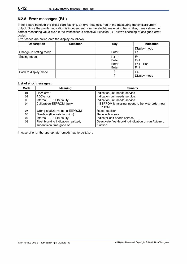
If the 8 bars beneath the digits start flashing, an error has occurred in the measuring transmitter/currentoutput. Since the pointer indication is independent from the electric measuring transmitter, it may show thecorrect measuring value even if the transmitter is defective. Function F41 allows checking of assigned errorcodes.
Error codes are called onto the display as follows:
Description Selection Key Indication
Change to setting mode Enter
Display mode
F1-
Setting mode 3 x →Enter
Enter
Enter
F4-F41F41 EnnF41
Back to display mode ↑↑
F4-Display mode
List of error messages :
Code Meaning Remedy
01
02
03
04
0506
07
08
RAM-error
ADC-error
Internal EEPROM faultyCalibration-EEPROM faulty
Wrong totalizer value in EEPROMOverflow (flow rate too high)Internal EEPROM faulty Float blocking indication realized,supervision time gone off
Indication unit needs service
Indication unit needs service
Indication unit needs service
If EEPROM is missing insert, -otherwise order new EEPROMReset totalizer
Reduce flow rateIndicator unit needs service
Deactivate float-blocking-indication or run Autozero function
In case of error the appropriate remedy has to be taken.
<6. ELECTRONIC TRANSMITTER (-E)> 6-13
All Rights Reserved. Copyright © 2003, Rota Yokogawa IM 01R01B02-00E-E 13th edition April 01, 2016 -00
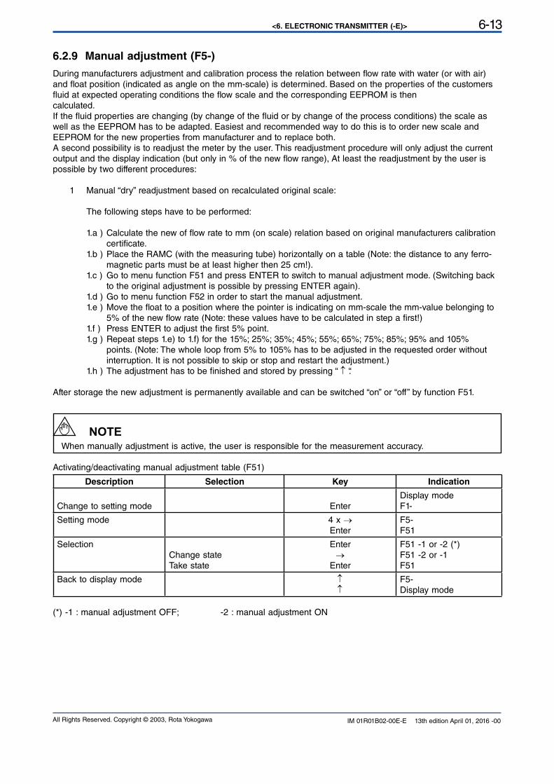
6.2.9 Manual adjustment (F5-)
During manufacturers adjustment and calibration process the relation between flow rate with water (or with air) and float position (indicated as angle on the mm-scale) is determined. Based on the properties of the customers fluid at expected operating conditions the flow scale and the corresponding EEPROM is then calculated.
If the fluid properties are changing (by change of the fluid or by change of the process conditions) the scale as well as the EEPROM has to be adapted. Easiest and recommended way to do this is to order new scale and EEPROM for the new properties from manufacturer and to replace both.A second possibility is to readjust the meter by the user. This readjustment procedure will only adjust the current output and the display indication (but only in % of the new flow range), At least the readjustment by the user is possible by two different procedures:
1 Manual “dry” readjustment based on recalculated original scale:
The following steps have to be performed:
1.a ) Calculate the new of flow rate to mm (on scale) relation based on original manufacturers calibration certificate.
1.b ) Place the RAMC (with the measuring tube) horizontally on a table (Note: the distance to any ferro- magnetic parts must be at least higher then 25 cm!).1.c ) Go to menu function F51 and press ENTER to switch to manual adjustment mode. (Switching back to the original adjustment is possible by pressing ENTER again).1.d ) Go to menu function F52 in order to start the manual adjustment.1.e ) Move the float to a position where the pointer is indicating on mm-scale the mm-value belonging to 5% of the new flow rate (Note: these values have to be calculated in step a first!)1.f ) Press ENTER to adjust the first 5% point.1.g ) Repeat steps 1.e) to 1.f) for the 15%; 25%; 35%; 45%; 55%; 65%; 75%; 85%; 95% and 105% points. (Note: The whole loop from 5% to 105% has to be adjusted in the requested order without interruption. It is not possible to skip or stop and restart the adjustment.)1.h ) The adjustment has to be finished and stored by pressing “ ↑ “.
After storage the new adjustment is permanently available and can be switched “on” or “off” by function F51.
When manually adjustment is active, the user is responsible for the measurement accuracy.
Activating/deactivating manual adjustment table (F51)
Description Selection Key Indication
Change to setting mode Enter
Display mode
F1-
Setting mode 4 x →Enter
F5-F51
Selection Change state
Take state
Enter
→Enter
F51 -1 or -2 (*)F51 -2 or -1F51
Back to display mode ↑↑
F5-Display mode
(*) -1 : manual adjustment OFF; -2 : manual adjustment ON
NOTE
<6. ELECTRONIC TRANSMITTER (-E)>6-14
All Rights Reserved. Copyright © 2003, Rota YokogawaIM 01R01B02-00E-E 13th edition April 01, 2016 -00
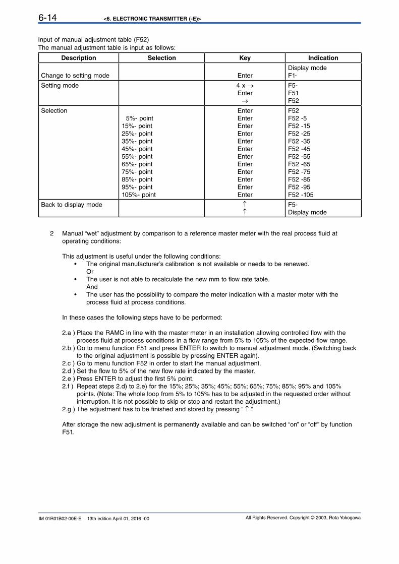
Input of manual adjustment table (F52)The manual adjustment table is input as follows:
Description Selection Key Indication
Change to setting mode Enter
Display mode
F1-
Setting mode 4 x →Enter
→
F5-F51F52
Selection 5%- point
15%- point25%- point35%- point45%- point55%- point65%- point75%- point85%- point95%- point105%- point
Enter
Enter
Enter
Enter
Enter
Enter
Enter
Enter
Enter
Enter
Enter
Enter
F52F52 -5F52 -15F52 -25F52 -35F52 -45F52 -55F52 -65F52 -75F52 -85F52 -95F52 -105
Back to display mode ↑↑
F5-Display mode
2 Manual “wet” adjustment by comparison to a reference master meter with the real process fluid at operating conditions:
This adjustment is useful under the following conditions:• The original manufacturer’s calibration is not available or needs to be renewed. Or
• The user is not able to recalculate the new mm to flow rate table. And
• The user has the possibility to compare the meter indication with a master meter with the process fluid at process conditions.
In these cases the following steps have to be performed:
2.a ) Place the RAMC in line with the master meter in an installation allowing controlled flow with the process fluid at process conditions in a flow range from 5% to 105% of the expected flow range.2.b ) Go to menu function F51 and press ENTER to switch to manual adjustment mode. (Switching back to the original adjustment is possible by pressing ENTER again).2.c ) Go to menu function F52 in order to start the manual adjustment.2.d ) Set the flow to 5% of the new flow rate indicated by the master.2.e ) Press ENTER to adjust the first 5% point.2.f ) Repeat steps 2.d) to 2.e) for the 15%; 25%; 35%; 45%; 55%; 65%; 75%; 85%; 95% and 105% points. (Note: The whole loop from 5% to 105% has to be adjusted in the requested order without interruption. It is not possible to skip or stop and restart the adjustment.)2.g ) The adjustment has to be finished and stored by pressing “ ↑ “.
After storage the new adjustment is permanently available and can be switched “on” or “off” by function F51.
<6. ELECTRONIC TRANSMITTER (-E)> 6-15
All Rights Reserved. Copyright © 2003, Rota Yokogawa IM 01R01B02-00E-E 13th edition April 01, 2016 -00
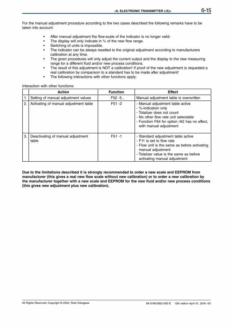
For the manual adjustment procedure according to the two cases described the following remarks have to be taken into account:
• After manual adjustment the flow-scale of the indicator is no longer valid. • The display will only indicate in % of the new flow range.• Switching of units is impossible.• The indicator can be always resetted to the original adjustment according to manufacturers calibration at any time.
• The given procedures will only adjust the current output and the display to the new measuring range for a different fluid and/or new process conditions.
• The result of this adjustment is NOT a calibration! If proof of the new adjustment is requested a real calibration by comparison to a standard has to be made after adjustment!
• The following interactions with other functions apply:
Interaction with other functions:
Action Function Effect
1. Setting of manual adjustment values F52 -5... Manual adjustment table is overwritten
2. Activating of manual adjustment table F51 -2 - Manual adjustment table active - %-indication only - Totalizer does not count - No other flow rate unit selectable- Function F64 for option /A2 has no effect, with manual adjustment
3. Deactivating of manual adjustment table
F51 -1 - Standard adjustment table active- F11 is set to flow rate- Flow unit is the same as before activating manual adjustment- Totalizer value is the same as before activating manual adjustment
Due to the limitations described it is strongly recommended to order a new scale and EEPROM from
manufacturer (this gives a real new flow scale without new calibration) or to order a new calibration by
the manufacturer together with a new scale and EEPROM for the new fluid and/or new process conditions
(this gives new adjustment plus new calibration).
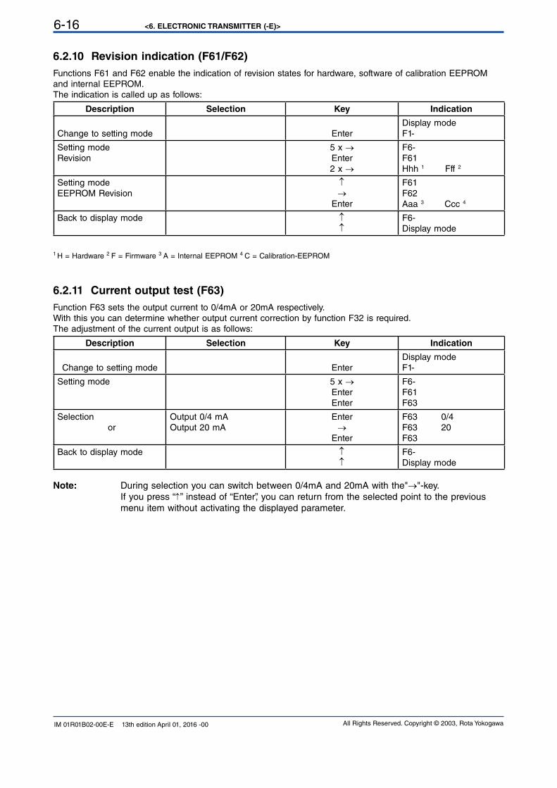
<6. ELECTRONIC TRANSMITTER (-E)>6-16
All Rights Reserved. Copyright © 2003, Rota YokogawaIM 01R01B02-00E-E 13th edition April 01, 2016 -00
6.2.10 Revision indication (F61/F62)
Functions F61 and F62 enable the indication of revision states for hardware, software of calibration EEPROMand internal EEPROM.The indication is called up as follows:
Description Selection Key Indication
Change to setting mode Enter
Display mode
F1-
Setting modeRevision
5 x →Enter
2 x →
F6-F61Hhh 1 Fff 2
Setting modeEEPROM Revision
↑→
Enter
F61F62Aaa 3 Ccc 4
Back to display mode ↑↑
F6-Display mode
1 H = Hardware 2 F = Firmware 3 A = Internal EEPROM 4 C = Calibration-EEPROM
6.2.11 Current output test (F63)
Function F63 sets the output current to 0/4mA or 20mA respectively.With this you can determine whether output current correction by function F32 is required.The adjustment of the current output is as follows:
Description Selection Key Indication
Change to setting mode Enter
Display mode
F1-
Setting mode 5 x →Enter
Enter
F6-F61F63
Selection or
Output 0/4 mA
Output 20 mA
Enter
→Enter
F63 0/4F63 20F63
Back to display mode ↑↑
F6-Display mode
Note: During selection you can switch between 0/4mA and 20mA with the"→"-key.
If you press “↑” instead of “Enter”, you can return from the selected point to the previous
menu item without activating the displayed parameter.
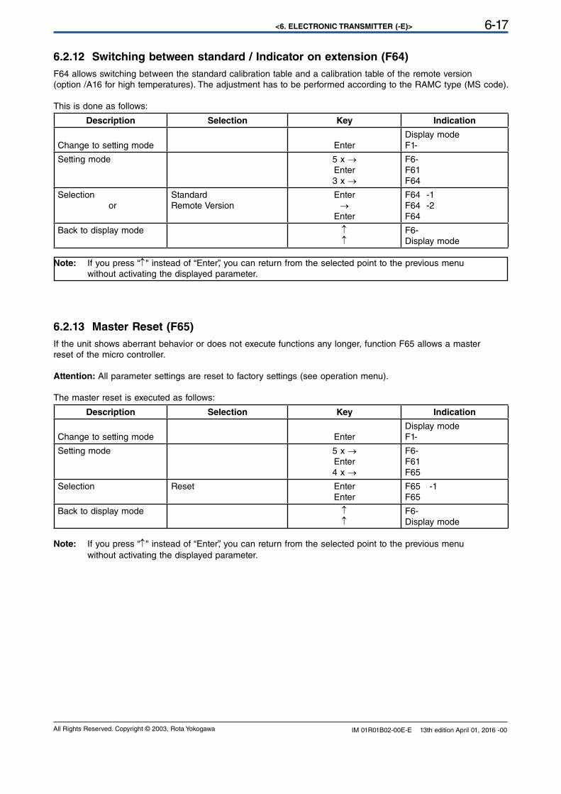
<6. ELECTRONIC TRANSMITTER (-E)> 6-17
All Rights Reserved. Copyright © 2003, Rota Yokogawa IM 01R01B02-00E-E 13th edition April 01, 2016 -00
6.2.12 Switching between standard / Indicator on extension (F64)
F64 allows switching between the standard calibration table and a calibration table of the remote version
(option /A16 for high temperatures). The adjustment has to be performed according to the RAMC type (MS code).
This is done as follows:
Description Selection Key Indication
Change to setting mode Enter
Display mode
F1-
Setting mode 5 x →Enter
3 x →
F6-F61F64
Selection or
StandardRemote Version
Enter
→Enter
F64 -1F64 -2F64
Back to display mode ↑↑
F6-Display mode
Note: If you press “↑" instead of “Enter”, you can return from the selected point to the previous menu
without activating the displayed parameter.
6.2.13 Master Reset (F65)
If the unit shows aberrant behavior or does not execute functions any longer, function F65 allows a masterreset of the micro controller.
Attention: All parameter settings are reset to factory settings (see operation menu).
The master reset is executed as follows:
Description Selection Key Indication
Change to setting mode Enter
Display mode
F1-
Setting mode 5 x →Enter
4 x →
F6-F61F65
Selection
Reset Enter
Enter
F65 -1F65
Back to display mode ↑↑
F6-Display mode
Note: If you press “↑" instead of “Enter”, you can return from the selected point to the previous menu
without activating the displayed parameter.
<6. ELECTRONIC TRANSMITTER (-E)>6-18
All Rights Reserved. Copyright © 2003, Rota YokogawaIM 01R01B02-00E-E 13th edition April 01, 2016 -00
6.2.14 Float blocking indication (F7-)
6.2.14.1 Function
Float
Pulsating movements of the flow medium (gasses, liquids) lead to fluctuations of the float and with that tofluctuations of the tap system/pointer. Therefore the electrical measuring signal permanently changes and withthat the display value and the output current value.
The fluctuations can be reduced with the help of the damping function “F21”. That shows however that themedium still flows and the float/the tap system is not blocked. This means that in most applications there is apermanently changing measuring signal which can be used for the recognition of the movement or the
blockade of the float.
Basic noise
Since it is an electronic evaluation circuit, permanently minimal fluctuations of the measuring signal appear. The basic noise is caused by vibrations in the plant as well as by temperature influences or external magneticfields. The basic noise also appears, if- no medium flows through the measuring pipe- the float and with that the tap system are in the rest position- the float/the tap system is blocked.
Float-Blocking-Indication
The function of the Float-Blocking-Indication allows the electronic transmitter to distinguish the fluctuations, which are caused by a moving float, with the fluctuations of the basic noise to state a fault status. If the measuringsignal does not exceed the autozero value during a defined supervision time, this is recognized as blockadeand an error condition is shown.
6.2.14.2 Operation
Switching on
At delivery of the equipment the Float-Blocking-Indication is turned off. By the function “F71 2” the Float-Blocking-Indication can be activated.
Autozero function
The autozero function is called to find out the level of basic noise in the application. This is started with thefunction “F74 1” and lasts for 90 seconds. While the autozero function is running the value “0.000” is displayedand the 4 bars will flash below the numbers. After approx. 80 seconds the current autozero value appears onthe display. This value gets stored and will not be lost after power off / on the RAMC or after switching off / onthe Float-Move-Detection-function. The stored value is typed over first after a renewed autozero.
Autozero without flow
To execute the autozero function the following expiry is recommended:- Plant in operation (measuring tube filled with medium)- Drive flow to zero (place float into rest position)- Raise the pointer to 10% to 20% of the flow and fix it on the scale with adhesive tapes or underlayed paper stripe .
- Start Autozero function by menu.- Check Autozero value after approx. 80 seconds.
During the Autozero function it absolutely has to be respected that:
- the RAMC is not moved by touching or using the 2 buttons.
- the pointer is protected against slipping.
- the tube is not exposed to strong tremors
If these prerequisites are not adhered, it comes to the inquiry of too high autozero results.
This leads that a relatively quiet flow can trigger the Float-Blocking-Indication.
<6. ELECTRONIC TRANSMITTER (-E)> 6-19
All Rights Reserved. Copyright © 2003, Rota Yokogawa IM 01R01B02-00E-E 13th edition April 01, 2016 -00
Autozero with flow
The Autozero function can be carried out also under flow, if the flow cannot be switched off. To this thefollowing expiry is recommended:- Plant in operation (measuring tube filled with medium)- Move flow to constant value (preferably between 10% and 40%)- Fix pointer on the oriented scale factor with adhesive tapes or underlayed paper stripe- Start Autozero function by menu.- Check Autozero value after approx. 80 seconds.
It has to be respected on this absolutely, for this the flow is constant during the Autozero duration!Normally at this variant higher Autozero results must be expected !
Autozero range
The factory default autozero value is zero (0.000).At the inquiry of the autozero value it has to be respected that the pointer / tap system are not in the rest
position. In this case the autozero value is zero and the Float-Move-Detection does not work.Normally the autozero value is smaller than 0.200. If higher results should appear in the application, a multipleinquiry of the autozero value is recommended to confirm the value.
Supervision range (measuring range)
The measuring range in which Float-Move-Detection is active lies between 5% and 105% of the maximum flowQmax (Factory Setting). With the help of the function “F72” this range can be reduced if a supervision is notpossible or not desired in the lower flow range. The range can be restricted to 15% or 30% to 105% (seepoint 3.1 to 3.3).
Supervision time (Time Out)
The supervision time of the measuring signal is 5 minutes (Factory Setting). If the measuring signal should notexceed the autozero value during this period, this is recognized as blockade and an error condition is shown.The supervision time can be increased with the function “F73” up to 15 minutes.
Indication of a blocking condition
After the recognition of the blockade the error code “08” is produced and the bars under the displayed
measurement value are flashing (see fault behavior). Simultaneously the current output is set to a value, whichenables a clear fault detection of a connected evaluation unit :
- 2 - wire 4-20 mA: Error condition: IA (IG) < 3.6 mA
- 3 - wire 4-20 mA: Error condition: IA < 0.0 mA
- 3 - wire 0-20 mA: Error condition: IA = 0.0 mA
<6. ELECTRONIC TRANSMITTER (-E)>6-20
All Rights Reserved. Copyright © 2003, Rota YokogawaIM 01R01B02-00E-E 13th edition April 01, 2016 -00
6.2.14.3 Unsuitable applications It is possible, that the Float-Blocking-Indication- Function does not work satisfactorily. This can be caused withdifferent factors which are explained briefly here. In these cases the function of the Float-Blocking-Indication isnot suitable for the respective application and it should be turned off.
Applications with gases
At applications with gases and float-damping it can happen, that the pulsating movements of the medium(and with that of the float) are damped so strongly in the measuring tube, that the measuring signal lies underthe autozero value and a Float-Blocking-Indication is not possible.
Applications with high viscous media
If a high viscous medium should be used in the plant, the damping can get so high by the high viscosity of
the flow that the measuring signal lies below the autozero value, and a Float-Blocking-Indication is notpossible.
Applications with quiet flow
If the plant has an extremely quiet flow (gases or liquids) ,the supervision range can be limited in the lowerflow range. Normally greater flow (>30%) causes greater medium flow deviations. The duration of thesupervision can be put to 15 minutes to reach a longer supervision time.
6.2.13.4 Parameter setting
Error message (F41)
Code Meaning Remedy
08 Float blockageSupervision time gone off
Check float in tube, clean tube if necessary.Deactivate float blocking indication or run Autozero function.
Factory defaults / Master Reset (F65)
The RAMC is adjusted at delivery (Factory Setting):
- F71 - 1 Float-Move-Detection OFF
- F72 - 1 Lower limit value of the supervision area 5 %
- F73 - 1 Supervision time (Time Out) 5 min
- F74 Autozero inactive Autozero value = 0
After Master Reset the following attitudes are given :
- F71 - 1 Float-Blocking-Indication OFF
- F72 - 1 Lower limit value of the supervision area 5 %
- F73 - 1 Supervision time (Time Out) 5 min
- F74 Autozero inactive Autozero value not changed
Damping (F21)
The selection of the damping value has no influence on the autozero value or the measurement value of the Float-Blocking-Indication !
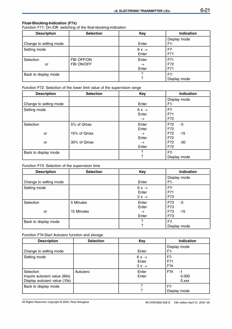
<6. ELECTRONIC TRANSMITTER (-E)> 6-21
All Rights Reserved. Copyright © 2003, Rota Yokogawa IM 01R01B02-00E-E 13th edition April 01, 2016 -00
Float-Blocking-Indication (F7x)Function F71: On-/Off- switching of the float-blocking-indication
Description Selection Key Indication
Change to setting mode Enter
Display mode
F1-
Setting mode 6 x →Enter
F7-F71
Selection or
FBI OFF/ONFBI ON/OFF
Enter
→Enter
F71 F72F71
Back to display mode ↑↑
F7-Display mode
Function F72: Selection of the lower limit value of the supervision range
Description Selection Key Indication
Change to setting mode Enter
Display mode
F1-
Setting mode 6 x →Enter
→
F7-F71F72
Selection
or
or
5% of Qmax
15% of Qmax
30% of Qmax
Enter
Enter
→Enter
→Enter
F72 -5F72F72 -15F72F72 -30F72
Back to display mode ↑↑
F7-Display mode
Function F73: Selection of the supervision time
Description Selection Key Indication
Change to setting mode Enter
Display mode
F1-
Setting mode 6 x →Enter
2 x →
F7-F71F73
Selection
or
5 Minutes
15 Minutes
Enter
Enter
→Enter
F73 -5F73F73 -15F73
Back to display mode ↑↑
F7-Display mode
Function F74:Start Autozero function and storage
Description Selection Key Indication
Change to setting mode Enter
Display mode
F1-
Setting mode 6 x →Enter
3 x →
F7-F71F74
SelectionInquire autozero value (80s)
Display autozero value (10s)
Autozero Enter
Enter
F74 -1 0.000
0.xxx
Back to display mode ↑↑
F7-Display mode
<6. ELECTRONIC TRANSMITTER (-E)>6-22
All Rights Reserved. Copyright © 2003, Rota YokogawaIM 01R01B02-00E-E 13th edition April 01, 2016 -00
Blank Page
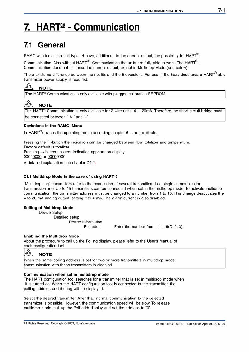
<7. HART-COMMUNICATION> 7-1
All Rights Reserved. Copyright © 2003, Rota Yokogawa IM 01R01B02-00E-E 13th edition April 01, 2016 -00
7.1 General
RAMC with indication unit type -H have, additional to the current output, the possibility for HART®-
Communication. Also without HART®- Communication the units are fully able to work. The HART®-
Communication does not influence the current output, except in Multidrop-Mode (see below).
There exists no difference between the not-Ex and the Ex versions. For use in the hazardous area a HART®-able
transmitter power supply is required.
The HART®-Communication is only available with plugged calibration-EEPROM
The HART®-Communication is only available for 2-wire units, 4 ... 20mA. Therefore the short-circuit bridge must
be connected between ´ A ´ and ´-´.
7. HART® - Communication
NOTE
NOTE
Deviations in the RAMC- Menu
In HART® devices the operating menu according chapter 6 is not available.
Pressing the ↑ -button the indication can be changed between flow, totalizer and temperature. Factory default is totalizer.Pressing → button an error indication appears on display.
00000000 or 00000000
A detailed explanation see chapter 7.4.2.
7.1.1 Multidrop Mode in the case of using HART 5
“Multidropping” transmitters refer to the connection of several transmitters to a single communication
transmission line. Up to 15 transmitters can be connected when set in the multidrop mode. To activate multidrop communication, the transmitter address must be changed to a number from 1 to 15. This change deactivates the 4 to 20 mA analog output, setting it to 4 mA. The alarm current is also disabled.
Setting of Multidrop Mode
Device Setup Detailed setup
Device Information
Poll addr Enter the number from 1 to 15(Def.: 0)
Enabling the Multidrop Mode
About the procedure to call up the Polling display, please refer to the User’s Manual of each configuration tool.
When the same polling address is set for two or more transmitters in multidrop mode,
communication with these transmitters is disabled.
Communication when set in multidrop mode
The HART configuration tool searches for a transmitter that is set in multidrop mode when it is turned on. When the HART configuration tool is connected to the transmitter, the polling address and the tag will be displayed.
Select the desired transmitter. After that, normal communication to the selected transmitter is possible. However, the communication speed will be slow. To release multidrop mode, call up the Poll addr display and set the address to “0”.
NOTE
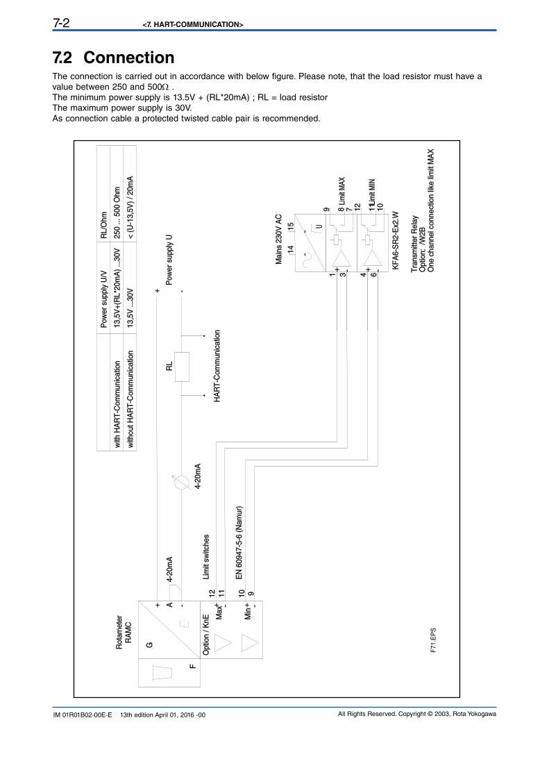
<7. HART-COMMUNICATION>7-2
All Rights Reserved. Copyright © 2003, Rota YokogawaIM 01R01B02-00E-E 13th edition April 01, 2016 -00
7.2 ConnectionThe connection is carried out in accordance with below figure. Please note, that the load resistor must have a value between 250 and 500Ω .
The minimum power supply is 13.5V + (RL*20mA) ; RL = load resistorThe maximum power supply is 30V.As connection cable a protected twisted cable pair is recommended.
15
4 631
14
12
10
11
8 79U
F
G
RA
MC
AP
ow
er
supply
U
Main
s 230V
AC
KF
A6-S
R2-E
x2.W
Optio
n: /W
2B
Tra
nsm
itter
Rela
y
Lim
it M
IN
Lim
it M
AX
Optio
n / K
nE
Rota
mete
r
4-2
0m
A
Max
Min
12
11
10 9
Lim
it sw
itches
EN
60947-5
-6 (
Nam
ur)
One c
hannel c
onnect
ion li
ke li
mit
MA
X
4-2
0m
A
RL
HA
RT
-Com
munic
atio
n
with
HA
RT
-Com
munic
atio
n
with
out H
AR
T-C
om
munic
atio
n
Pow
er
supply
U/V
RL/O
hm
13,5
V+
(RL*2
0m
A)
...3
0V
13,5
V ...30V
< (
U-1
3,5
V)
/ 20m
A
250 ... 5
00 O
hm
-+
-+
-+-+
~~
+ - + -
F7
1.E
PS
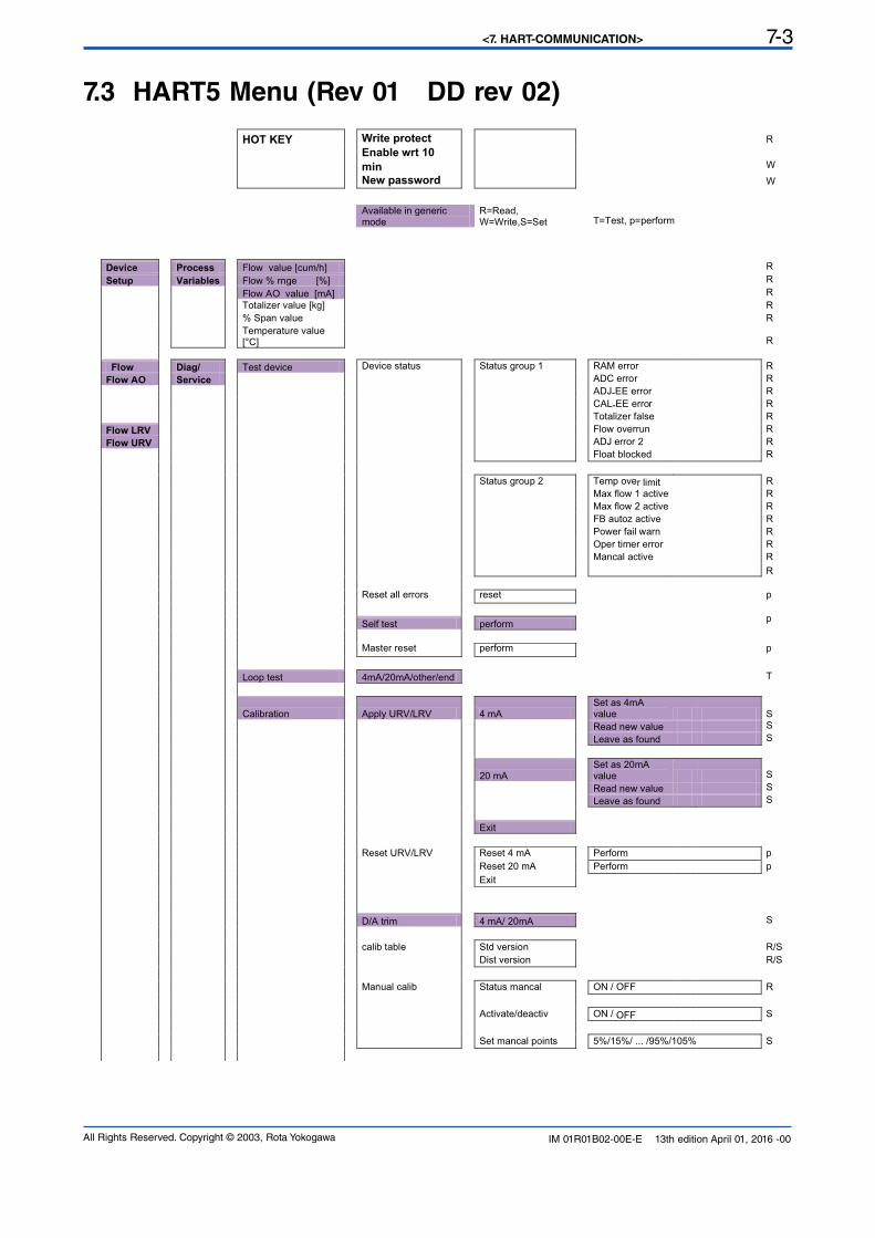
<7. HART-COMMUNICATION> 7-3
All Rights Reserved. Copyright © 2003, Rota Yokogawa IM 01R01B02-00E-E 13th edition April 01, 2016 -00
7.3 HART5 Menu (Rev 01 DD rev 02)
HOT KEY Write protect R
Enable wrt 10
min W
New password W
Available in generic mode
R=Read, W=Write,S=Set T=Test, p=perform
Device Process Flow value [cum/h] R
Setup Variables Flow % rnge [%] R
Flow AO value [mA] R
Totalizer value [kg] R
% Span value R
Temperature value [°C] R
Flow Diag/ Test device Device status Status group 1 RAM error R
Flow AO Service ADC error R
ADJ-EE error R
CAL-EE error R
Totalizer false R
Flow LRV Flow overrun R
Flow URV ADJ error 2 R
Float blocked R
Status group 2 Temp over limit R
Max flow 1 active R
Max flow 2 active R
FB autoz active R
Power fail warn R
Oper timer error R
Mancal active R
R
Reset all errors reset p
Self test perform p
Master reset perform p
Loop test 4mA/20mA/other/end T
Calibration Apply URV/LRV 4 mA Set as 4mA value S
Read new value S
Leave as found S
20 mA Set as 20mA value S
Read new value S
Leave as found S
Exit
Reset URV/LRV Reset 4 mA Perform p
Reset 20 mA Perform p
Exit
D/A trim 4 mA/ 20mA S
calib table Std version R/S
Dist version R/S
Manual calib Status mancal ON / OFF R
Activate/deactiv ON / OFF S
Set mancal points 5%/15%/ ... /95%/105% S
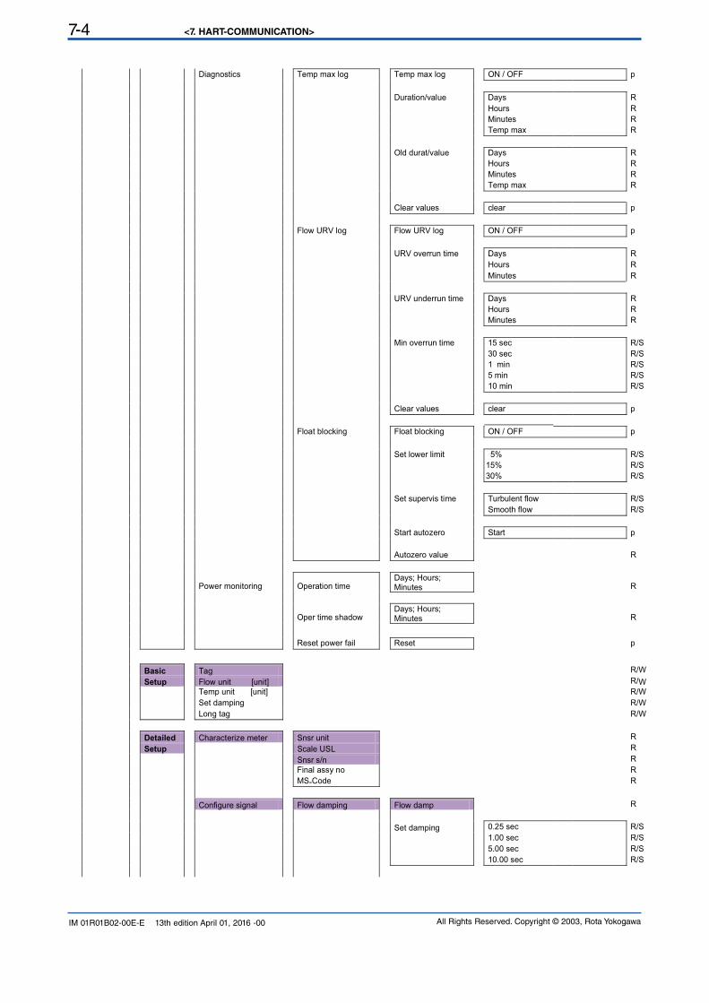
<7. HART-COMMUNICATION>7-4
All Rights Reserved. Copyright © 2003, Rota YokogawaIM 01R01B02-00E-E 13th edition April 01, 2016 -00
Diagnostics Temp max log Temp max log ON / OFF p
Duration/value Days R
Hours R
Minutes R
Temp max R
Old durat/value Days R
Hours R
Minutes R
Temp max R
Clear values clear p
Flow URV log Flow URV log ON / OFF p
URV overrun time Days R
Hours R
Minutes R
URV underrun time Days R
Hours R
Minutes R
Min overrun time 15 sec R/S
30 sec R/S
1 min R/S
5 min R/S
10 min R/S
Clear values clear p
Float blocking Float blocking ON / OFF p
Set lower limit 5% R/S
15% R/S
30% R/S
Set supervis time Turbulent flow R/S
Smooth flow R/S
Start autozero Start p
Autozero value R
Power monitoring Operation time Days; Hours; Minutes R
Oper time shadow Days; Hours; Minutes R
Reset power fail Reset p
Basic Tag R/W
Setup Flow unit [unit] R/W
Temp unit [unit] R/W
Set damping R/W
Long tag R/W
Detailed Characterize meter Snsr unit R
Setup Scale USL R
Snsr s/n R
Final assy no R
MS-Code R
Configure signal Flow damping Flow damp R
Set damping 0.25 sec R/S
1.00 sec R/S
5.00 sec R/S
10.00 sec R/S
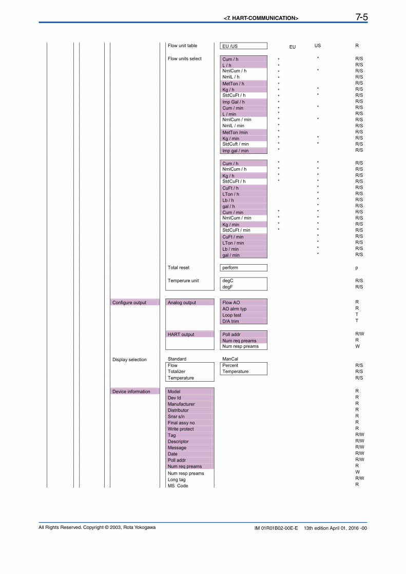
<7. HART-COMMUNICATION> 7-5
All Rights Reserved. Copyright © 2003, Rota Yokogawa IM 01R01B02-00E-E 13th edition April 01, 2016 -00
Flow unit table EU /US EU US R
Flow units select Cum / h * * R/S
L / h * R/S
NmlCum / h * * R/S
NmlL / h * R/S
MetTon / h * R/S
Kg / h * * R/S
StdCuFt / h * * R/S
Imp Gal / h * R/S
Cum / min * * R/S
L / min * R/S
NmlCum / min * * R/S
NmlL / min * R/S
MetTon /min * R/S
Kg / min * * R/S
StdCuft / min * * R/S
Imp gal / min * R/S
Cum / h * * R/S
NmlCum / h * * R/S
Kg / h * * R/S
StdCuFt / h * * R/S
CuFt / h * R/S
LTon / h * R/S
Lb / h * R/S
gal / h * R/S
Cum / min * * R/S
NmlCum / min * * R/S
Kg / min * * R/S
StdCuFt / min * * R/S
CuFt / min * R/S
LTon / min * R/S
Lb / min * R/S
gal / min * R/S
Total reset perform p
Temperure unit degC R/S
degF R/S
Configure output Analog output Flow AO R
AO alrm typ R
Loop test T
D/A trim T
HART output Poll addr R/W
Num req preams R
Num resp preams W
Display selection Standard ManCal
Flow Percent R/S
Totalizer Temperature R/S
Temperature R/S
Device information Model R
Dev Id R
Manufacturer R
Distributor R
Snsr s/n R
Final assy no R
Write protect R
Tag R/W
Descriptor R/W
Message R/W
Date R/W
Poll addr R/W
Num req preams R
Num resp preams W
Long tag R/W
MS Code R
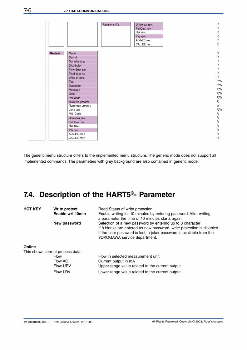
<7. HART-COMMUNICATION>7-6
All Rights Reserved. Copyright © 2003, Rota YokogawaIM 01R01B02-00E-E 13th edition April 01, 2016 -00
Revisions #´s Universal rev. R
Fld Dev. rev. R
HW rev.: R
FW rev.: R
ADJ-EE rev.: R
CAL-EE rev.: R
Review Model R
Dev Id R
Manufacturer R
Distributor R
Flow Snsr s/n R
Final assy no R
Write protect R
Tag R/W
Descriptor R/W
Message R/W
Date R/W
Poll addr R/W
Num req preams R
Num resp preams W
Long tag R/W
MS Code R
Universal rev. R
Fld. Dev. rev. R
HW rev.: R
FW rev.: R
ADJ-EE rev.: R
CAL-EE rev.: R
7.4. Description of the HART5®- Parameter
HOT KEY Write protect Read Status of write protection Enable wrt 10min Enable writing for 10 minutes by entering password. After writing
a parameter the time of 10 minutes starts again.
New password Selection of a new password by entering up to 8 character If 8 blanks are entered as new password, write protection is disabled.
If the user password is lost, a joker password is available from the YOKOGAWA service department.
Online
This shows current process data. Flow Flow in selected measurement unit Flow AO Current output in mA Flow URV Upper range value related to the current output
Flow LRV Lower range value related to the current output
The generic menu structure differs to the implemented menu structure. The generic mode does not support all
implemented commands. The parameters with grey background are also contained in generic mode.
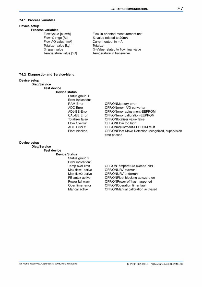
<7. HART-COMMUNICATION> 7-7
All Rights Reserved. Copyright © 2003, Rota Yokogawa IM 01R01B02-00E-E 13th edition April 01, 2016 -00
7.4.1 Process variables
Device setup
Process variables
Flow value [cum/h] Flow in oriented measurement unit Flow % rnge [%] %-value related to 20mA Flow AO value [mA] Current output in mA Totalizer value [kg] Totalizer % span value %-Value related to flow final value Temperature value [°C] Temperature in transmitter
7.4.2 Diagnostic- and Service-Menu
Device setup
Diag/Service
Test device
Device status
Status group 1 Error indication:
RAM Error OFF/ON Memory error ADC Error OFF/ON error A/D converter ADJ-EE-Error OFF/ON error adjustment-EEPROM CAL-EE Error OFF/ON error calibration-EEPROM Totalizer false OFF/ON totalizer value false Flow Overrun OFF/ON Flow too high ADJ Error 2 OFF/ON adjustment-EEPROM fault Float blocked OFF/ON Float-Move-Detection recognized, supervision time passed
Device setup
Diag/Service
Test device
Device Status
Status group 2 Error indication:
Temp over limit OFF/ON Temperature exceed 70°C Max flow1 active OFF/ON URV overrun Max flow2 active OFF/ON URV underrun FB autoz active OFF/ON Float blocking autozero on Power fail warn OFF/ON Power off has happened Oper timer error OFF/ON Operation timer fault Mancal active OFF/ON Manual calibration activated
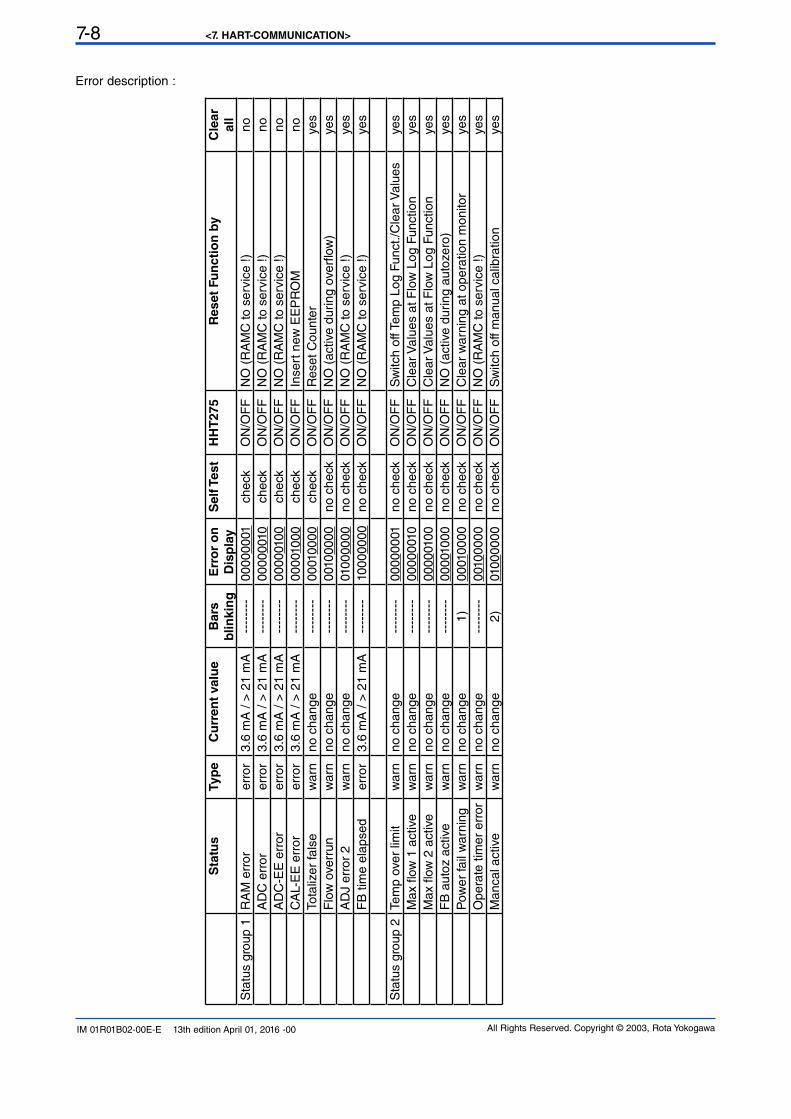
<7. HART-COMMUNICATION>7-8
All Rights Reserved. Copyright © 2003, Rota YokogawaIM 01R01B02-00E-E 13th edition April 01, 2016 -00
Error description :
Sta
tus
Ty
pe
Cu
rre
nt
va
lue
Ba
rs
blin
kin
g
Err
or
on
Dis
pla
y
Se
lf T
es
tH
HT
275
Reset
Fu
ncti
on
by
Cle
ar
all
Sta
tus
grou
p 1
RA
M e
rror
err
or
3.6
mA
/ >
21
mA
----
----
00
00
00
01
ch
eck
ON
/OF
FN
O (
RA
MC
to s
ervi
ce !)
no
AD
C e
rror
err
or
3.6
mA
/ >
21
mA
----
----
00
00
0010
ch
eck
ON
/OF
FN
O (
RA
MC
to s
ervi
ce !)
no
AD
C-E
E e
rror
err
or
3.6
mA
/ >
21
mA
----
----
00
00
010
0ch
eck
ON
/OF
FN
O (
RA
MC
to s
ervi
ce !)
no
CA
L-E
E e
rror
err
or
3.6
mA
/ >
21
mA
----
----
00
0010
00
ch
eck
ON
/OF
FIn
sert
new
EE
PR
OM
no
Tota
lizer
fals
ew
arn
no
ch
an
ge
----
----
00
010
00
0ch
eck
ON
/OF
FR
eset C
ounte
rye
s
Flo
w o
verr
unw
arn
no
ch
an
ge
----
----
0010
00
00
no
ch
eck
ON
/OF
FN
O (
activ
e du
ring
over
flow
)ye
s
AD
J e
rror
2w
arn
no
ch
an
ge
----
----
010
00
00
0n
o c
he
ck
ON
/OF
FN
O (
RA
MC
to s
ervi
ce !)
ye
s
FB
tim
e el
apse
derr
or
3.6
mA
/ >
21
mA
----
----
10
00
00
00
no
ch
eck
ON
/OF
FN
O (
RA
MC
to s
ervi
ce !)
ye
s
Sta
tus
grou
p 2
Tem
p ov
er li
mit
warn
no
ch
an
ge
----
----
00
00
00
01
no
ch
eck
ON
/OF
FS
witc
h of
f Tem
p Lo
g Fu
nct./
Cle
ar V
alue
sye
s
Max
flow
1 a
ctiv
ew
arn
no
ch
an
ge
----
----
00
00
0010
no
ch
eck
ON
/OF
FC
lear
Val
ues
at F
low
Log
Fun
ctio
nye
s
Max
flow
2 a
ctiv
ew
arn
no
ch
an
ge
----
----
00
00
010
0n
o c
he
ck
ON
/OF
FC
lear
Val
ues
at F
low
Log
Fun
ctio
nye
s
FB
aut
oz a
ctiv
ew
arn
no
ch
an
ge
----
----
00
0010
00
no
ch
eck
ON
/OF
FN
O (
activ
e du
ring
auto
zero
)ye
s
Pow
er fa
il w
arni
ngw
arn
no
ch
an
ge
1)
00
010
00
0n
o c
he
ck
ON
/OF
FC
lear
warn
ing a
t opera
tion m
onitor
ye
s
Opera
te t
imer
err
or
warn
no
ch
an
ge
----
----
0010
00
00
no
ch
eck
ON
/OF
FN
O (
RA
MC
to s
ervi
ce !)
ye
s
Mancal active
warn
no
ch
an
ge
2)
010
00
00
0n
o c
he
ck
ON
/OF
FS
witc
h of
f man
ual c
alib
ratio
nye
s
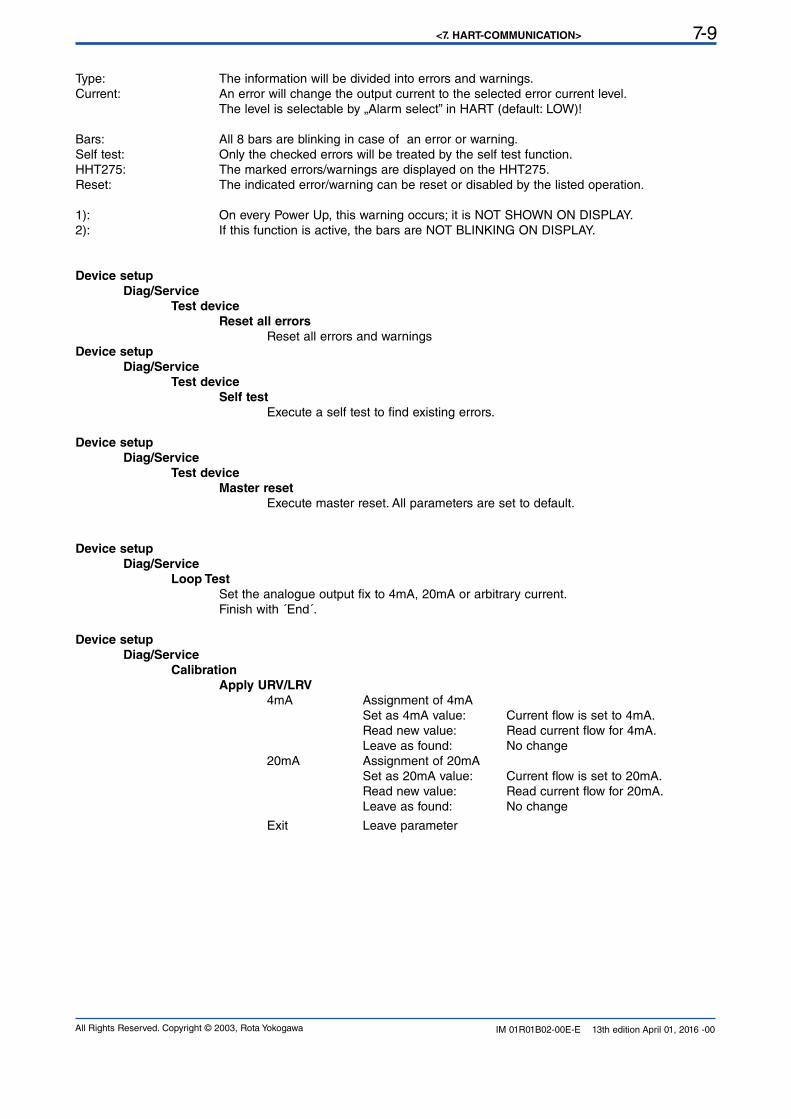
<7. HART-COMMUNICATION> 7-9
All Rights Reserved. Copyright © 2003, Rota Yokogawa IM 01R01B02-00E-E 13th edition April 01, 2016 -00
Type: The information will be divided into errors and warnings.Current: An error will change the output current to the selected error current level.
The level is selectable by „Alarm select” in HART (default: LOW)!
Bars: All 8 bars are blinking in case of an error or warning.
Self test: Only the checked errors will be treated by the self test function.HHT275: The marked errors/warnings are displayed on the HHT275.Reset: The indicated error/warning can be reset or disabled by the listed operation.
1): On every Power Up, this warning occurs; it is NOT SHOWN ON DISPLAY.2): If this function is active, the bars are NOT BLINKING ON DISPLAY.
Device setup
Diag/Service
Test device
Reset all errors
Reset all errors and warnings
Device setup
Diag/Service
Test device
Self test
Execute a self test to find existing errors.
Device setup
Diag/Service
Test device
Master reset
Execute master reset. All parameters are set to default.
Device setup
Diag/Service
Loop Test
Set the analogue output fix to 4mA, 20mA or arbitrary current. Finish with ´End´.
Device setup
Diag/Service
Calibration
Apply URV/LRV
4mA Assignment of 4mA
Set as 4mA value: Current flow is set to 4mA. Read new value: Read current flow for 4mA.
Leave as found: No change 20mA Assignment of 20mA
Set as 20mA value: Current flow is set to 20mA. Read new value: Read current flow for 20mA.
Leave as found: No change
Exit Leave parameter
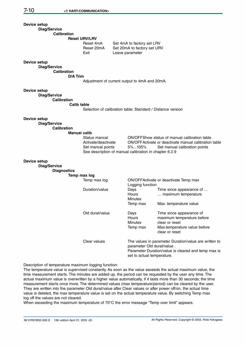
<7. HART-COMMUNICATION>7-10
All Rights Reserved. Copyright © 2003, Rota YokogawaIM 01R01B02-00E-E 13th edition April 01, 2016 -00
Device setup
Diag/Service
Calibration
Reset URV/LRV
Reset 4mA Set 4mA to factory set LRV Reset 20mA Set 20mA to factory set URV Exit Leave parameter
Device setup
Diag/Service
Calibration
D/A Trim
Adjustment of current output to 4mA and 20mA.
Device setup
Diag/Service
Calibration
Calib table
Selection of calibration table: Standard / Distance version
Device setup
Diag/Service
Calibration
Manual calib
Status mancal ON/OFF Show status of manual calibration table Activate/deactivate ON/OFF Activate or deactivate manual calibration table Set mancal points 5%...105% Set manual calibration points See description of manual calibration in chapter 6.2.9
Device setup
Diag/Service
Diagnostics
Temp max log
Temp max log ON/OFF Activate or deactivate Temp max Logging function Duration/value Days Time since appearance of … Hours … maximum temperature Minutes
Temp max Max. temperature value
Old durat/value Days Time since appearance of Hours maximum temperature before Minutes clear or reset
Temp max Max.temperature value before clear or reset
Clear values The values in parameter Duration/value are written to parameter Old durat/value .
Parameter Duration/value is cleared and temp max is set to actual temperature.
Description of temperature maximum logging function:The temperature value is supervised constantly. As soon as the value exceeds the actual maximum value, thetime measurement starts. The minutes are added up, the period can be requested by the user any time. Theactual maximum value is overwritten by a higher value automatically, if it lasts more than 30 seconds; the timemeasurement starts once more. The determined values (max temperature/period) can be cleared by the user. They are written into the parameter Old durat/value after Clear values or after power off/on, the actual time value is deleted, the max temperature value is set on the actual temperature value. By switching Temp max log off the values are not cleared.
When exceeding the maximum temperature of 70°C the error message “Temp over limit” appears.
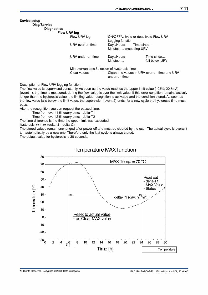
<7. HART-COMMUNICATION> 7-11
All Rights Reserved. Copyright © 2003, Rota Yokogawa IM 01R01B02-00E-E 13th edition April 01, 2016 -00
Device setup
Diag/Service
Diagnostics
Flow URV log
Flow URV log ON/OFF Activate or deactivate Flow URV Logging function URV overrun time Days/Hours Time since… Minutes … exceeding URV
URV underrun time Days/Hours Time since… Minutes … fall below URV
Min overrun time Selection of hysteresis time Clear values Clears the values in URV overrun time and URV underrun time
Description of Flow URV logging function :The flow value is supervised constantly. As soon as the value reaches the upper limit value (103%; 20.5mA) (event 1), the time is measured, during the flow value is over the limit value. If this error condition remains actively longer than the hysteresis value, the limiting value recognition is activated and the condition stored. As soon as
the flow value falls below the limit value, the supervision (event 2) ends, for a new cycle the hysteresis time must pass.
After the recognition you can request the passed time:
Time from event1 till query time: delta-T1 Time from event2 till query time: delta-T2The time difference is the time the upper limit was exceeded.hysteresis <= t <= (delta-t1 - delta-t2)
The stored values remain unchanged after power off and must be cleared by the user. The actual cycle is overwrit-ten automatically by a new one. Therefore only the last cycle is always stored. The default value for hysteresis is 30 seconds.
-30
-20
-10
0
10
20
30
40
50
60
70
80
0 2 4 6 8 10 12 14 16 18 20 22 24 26 28 30
Temperature
delta-T1 (day; h; min)
Reset to actual value- on Clear MAX value
Read out- delta-T1- MAX Value- Status
MAX Temp. = 70 °C
t1
Time [h]
Tem
pera
ture
[°C
]
Temperature MAX function
<7. HART-COMMUNICATION>7-12
All Rights Reserved. Copyright © 2003, Rota YokogawaIM 01R01B02-00E-E 13th edition April 01, 2016 -00
0
10
20
30
40
50
60
70
80
90
100
110
0 5 10 15 20 25 304
5
6
7
8
9
10
11
12
13
14
15
16
17
18
19
20
21
Output CurrentFlow Value
hysteresis (> 30 sec)
t2
delta-T2 (day; h; min)
delta-T1 (day; h; min)
Read out(max. 1 Event)
MAX Value = 103 % (20.5 mA)
t1Time [min]
Flo
w [%
]
Curr
ent [m
A]
Flow URV Funktion
F73.EPS
Device setup
Diag/Service
Diagnostics
Float blocking
Float blocking ON/OFF Activate or deactivate float blocking
Set lower limit 5%/15%/30% Set lower limit of supervision range
Set supervise time Turbulent flow Smooth flow
Start autozero Start Autozero value Shows autozero value Detailed description of float blocking function see chapter 6.2.12.
Device setup
Diag/Service
Power monitoring
Operation time Days Time since last power on. Hours
Minutes
Oper time shadow Days Time from… Hours … previous power on… Minutes … to power off.
Reset power fail Power fail warning is cleared.
Description of power monitoring function:
After power on the minutes are counted in parameter Operation time.
At power off the time from parameter Operation time is stored in parameter Oper time shadow.
After power off/on the power fail warning is set. It can be cleared by Reset power fail.
<7. HART-COMMUNICATION> 7-13
All Rights Reserved. Copyright © 2003, Rota Yokogawa IM 01R01B02-00E-E 13th edition April 01, 2016 -00
7.4.3 Basic-Setup Menu
Device setup
Basic setup
Tag Tag Number (8 characters) Flow unit Flow measurement unit Temp unit Temperature measurement unit Set damping Obtained damping Long tag Long Tag Number (24 characters)
7.4.4 Detailed-Setup Menu
Device setup
Detailed setup
Characterize meter
Details on the measuring tube.
Snsr unit Flow measurement unit in accordance with scale Scale USL Upper sensor limit related to flow Snsr s/n Serial number of the measuring tube Final assy no. Number of final assembly MS Code Ordering code of the device
Device setup
Detailed setup
Configure signal
Flow damping
Flow damping Read damping value Set damping 0.25s/1.00s/5.00s/10.00s
Device setup
Detailed setup
Configure signal
Flow unit table
EU/US Read preset unit set (see chapter 6-2-2)
Device setup
Detailed setup
Configure signal
Flow unit select
Selectable flow units: EU US
Cum/h Cum/h
L/h NmlCum/h NmlCum/h Kg/h NmlL/h StdCuFt/h MetTon/h CuFt/h Kg/h Lton/h StdCuFt/h Lb/h ImpGal/h gal/h
Cum/min Cum/min
L/min NmlCum/min NmlCum/min Kg/min NmlL/min StdCuFt/min MetTon/min CuFt/min Kg/min Lton/min StdCuFt/min Lb/min
ImpGal/min gal/min
<7. HART-COMMUNICATION>7-14
All Rights Reserved. Copyright © 2003, Rota YokogawaIM 01R01B02-00E-E 13th edition April 01, 2016 -00
Device setup
Detailed setup
Configure signal
Total reset
Reset totalizer
Device setup
Detailed setup
Configure signal
Temperature unit
degC / degF Select temperature unit
Device setup
Detailed setup
Configure output
Analog output
Indication, test and adjustment of current output : Flow AO Read Current output in mA
AO Alm typ Lo current < 3,6mA at error Hi current > 21.0mA at error Loop Test Set the analogue output fix to 4mA, 20mA or arbitrary current.
Finish with ´End´. D/A Trim Adjustment of current output at 4mA and 20mA.
Device setup
Detailed setup
Configure output
HART output
HART® specific parameter :
Poll Addr Poll Address (Function see above) (Def.: 0)
Num req preams Number of leading FF to HART® unit (Def.: 5)
Num resp pream Number of leading FF from HART®-unit (Def.:5)
Device setup
Detailed setup
Display selection
Selection of measuring value on display, Different if manual calibration is activated.
For standard calibration table: Flow / Totalizer / Temperature For manual calibration table: Percent / Temperature
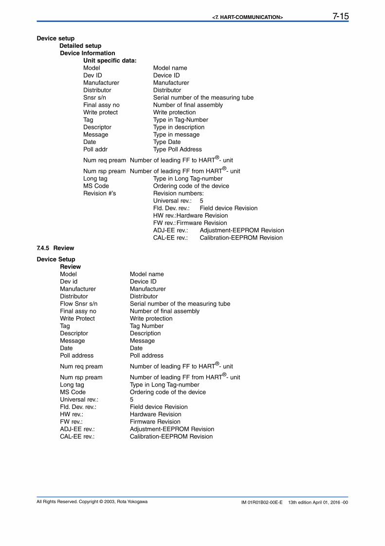
<7. HART-COMMUNICATION> 7-15
All Rights Reserved. Copyright © 2003, Rota Yokogawa IM 01R01B02-00E-E 13th edition April 01, 2016 -00
Device setup
Detailed setup
Device Information
Unit specific data:
Model Model name
Dev ID Device ID
Manufacturer Manufacturer
Distributor Distributor
Snsr s/n Serial number of the measuring tube Final assy no Number of final assembly Write protect Write protection
Tag Type in Tag-Number Descriptor Type in description Message Type in message Date Type Date Poll addr Type Poll Address
Num req pream Number of leading FF to HART®- unit
Num rsp pream Number of leading FF from HART®- unit
Long tag Type in Long Tag-number MS Code Ordering code of the device Revision #’s Revision numbers:
Universal rev.: 5 Fld. Dev. rev.: Field device Revision HW rev.: Hardware Revision
FW rev.: Firmware Revision ADJ-EE rev.: Adjustment-EEPROM Revision CAL-EE rev.: Calibration-EEPROM Revision
7.4.5 Review
Device Setup
Review
Model Model name
Dev id Device ID
Manufacturer Manufacturer
Distributor Distributor
Flow Snsr s/n Serial number of the measuring tube Final assy no Number of final assembly Write Protect Write protection
Tag Tag Number Descriptor Description
Message Message
Date Date
Poll address Poll address
Num req pream Number of leading FF to HART®- unit
Num rsp pream Number of leading FF from HART®- unit
Long tag Type in Long Tag-number MS Code Ordering code of the device Universal rev.: 5 Fld. Dev. rev.: Field device Revision HW rev.: Hardware Revision
FW rev.: Firmware Revision ADJ-EE rev.: Adjustment-EEPROM Revision CAL-EE rev.: Calibration-EEPROM Revision
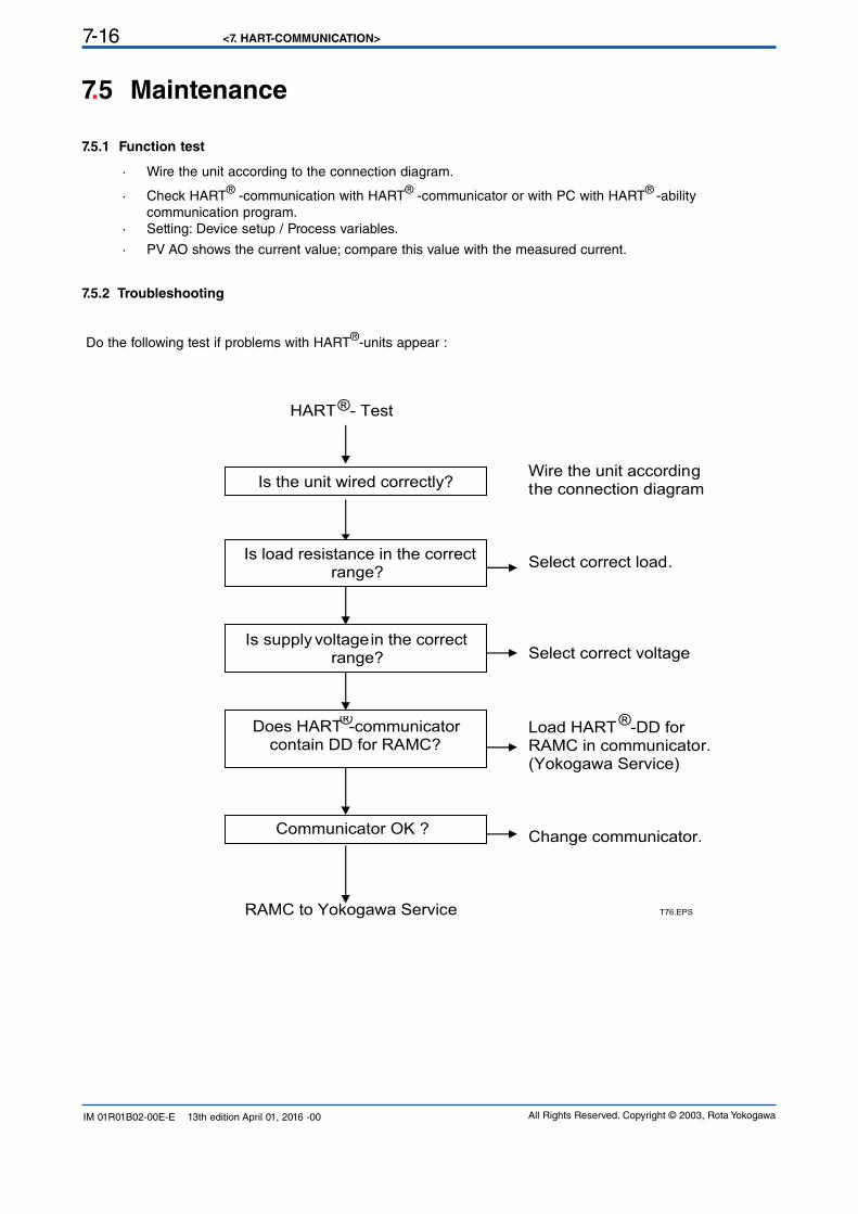
<7. HART-COMMUNICATION>7-16
All Rights Reserved. Copyright © 2003, Rota YokogawaIM 01R01B02-00E-E 13th edition April 01, 2016 -00
7.5 Maintenance
7.5.1 Function test
· Wire the unit according to the connection diagram.
· Check HART® -communication with HART® -communicator or with PC with HART® -ability
communication program.
· Setting: Device setup / Process variables.
· PV AO shows the current value; compare this value with the measured current.
7.5.2 Troubleshooting
Do the following test if problems with HART®-units appear :
Wire the unit according the connection diagram Select correct load. Select correct voltage
Load HART® -DD for RAMC in communicator. (Yokogawa Service) Change communicator. RAMC to Yokogawa Service
Is the unit wired correctly?
Is load resistance in the correct range?
Is supply voltage in the correct range?
Does HART®-communicator contain DD for RAMC?
Communicator OK ?
T76.EPS
HART - Test®
<8. SERVICE> 8-1
All Rights Reserved. Copyright © 2003, Rota Yokogawa IM 01R01B02-00E-E 13th edition April 01, 2016 -00
8. Service
8.1.1 Function test
Checking free movement of pointer:
- Remove housing cover (4 screws on housing type 66).
- After deflecting the pointer by hand, it must return to measurement value. If the pointer pivots to different values upon repeated deflections, there is too much friction in the bearings. In this case, send indication unit to service.
Checking free movement of float:- First, free movement of pointer has to be ascertained.- Check visually if pointer follows each flow rate change. If not, clean float and measuring tube.
Unit with electronic transmitter:- The display must show values corresponding to indication function and measuring unit settings.- The bars under the 8 digits must not flash. If an error occurs, the corresponding countermeasure (refer to chapter 6.2.8 error messages) has to be taken or the unit has to be sent to service.
- Without flow, the output current must be 0 or 4 mA. At a flow rate of 100% the current must be 20 mA.
Additional function test for HART® units (-H)
- check HART® communication using a HART® Handheld terminal or a PC with HART® communication
software.
- Setting: Device setup / Process variables- PV AO shows the current value that should be delivered at output – Check this value using a multimeter.
8.1.2 Measuring tube, float
The RAMC is maintenance-free. If contamination of the measuring tube impairs the mobility of the float, the tube and the float have to be cleaned. To do this, the RAMC has to be removed from the pipe.Replacement or cleaning of the float:- Remove RAMC from the pipe.
- Remove upper retainer from metering tube.
- Take float stopper and float out through the top of metering tube.- Clean float and metering cone- Insert float and float stopper into the metering tube.- Set retainer into tube.- Check float for free movement.- Install RAMC to the pipe.
Attention: Do not expose float to strong alternating magnetic fields. The float and especially its measuring edge must not be damaged.
8.1 Maintenance
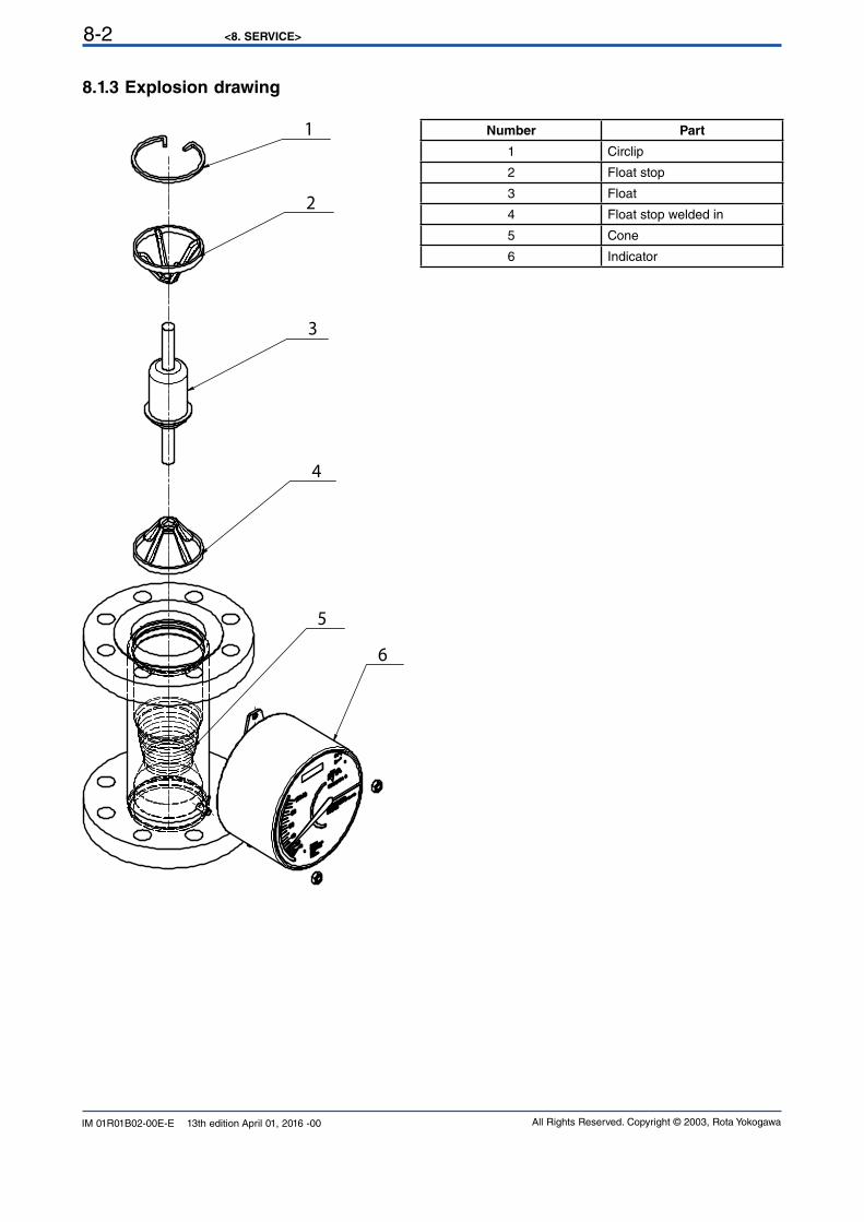
<8. SERVICE>8-2
All Rights Reserved. Copyright © 2003, Rota YokogawaIM 01R01B02-00E-E 13th edition April 01, 2016 -00
8.1.3 Explosion drawing
1
2
3
4
6
5
Number Part
1 Circlip
2 Float stop
3 Float
4 Float stop welded in
5 Cone
6 Indicator
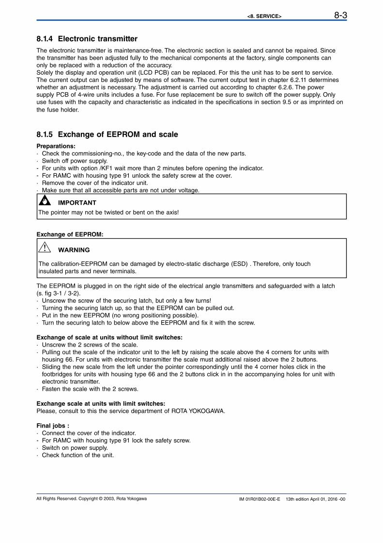
<8. SERVICE> 8-3
All Rights Reserved. Copyright © 2003, Rota Yokogawa IM 01R01B02-00E-E 13th edition April 01, 2016 -00
8.1.4 Electronic transmitter
The electronic transmitter is maintenance-free. The electronic section is sealed and cannot be repaired. Sincethe transmitter has been adjusted fully to the mechanical components at the factory, single components canonly be replaced with a reduction of the accuracy.
Solely the display and operation unit (LCD PCB) can be replaced. For this the unit has to be sent to service.The current output can be adjusted by means of software. The current output test in chapter 6.2.11 determineswhether an adjustment is necessary. The adjustment is carried out according to chapter 6.2.6. The powersupply PCB of 4-wire units includes a fuse. For fuse replacement be sure to switch off the power supply. Onlyuse fuses with the capacity and characteristic as indicated in the specifications in section 9.5 or as imprinted on the fuse holder.
8.1.5 Exchange of EEPROM and scale
Preparations:
· Check the commissioning-no., the key-code and the data of the new parts.
· Switch off power supply.- For units with option /KF1 wait more than 2 minutes before opening the indicator.- For RAMC with housing type 91 unlock the safety screw at the cover.
· Remove the cover of the indicator unit.
· Make sure that all accessible parts are not under voltage.
The pointer may not be twisted or bent on the axis!
Exchange of EEPROM:
The calibration-EEPROM can be damaged by electro-static discharge (ESD) . Therefore, only touch insulated parts and never terminals.
The EEPROM is plugged in on the right side of the electrical angle transmitters and safeguarded with a latch(s. fig 3-1 / 3-2).
· Unscrew the screw of the securing latch, but only a few turns!· Turning the securing latch up, so that the EEPROM can be pulled out.· Put in the new EEPROM (no wrong positioning possible).· Turn the securing latch to below above the EEPROM and fix it with the screw.
Exchange of scale at units without limit switches:
· Unscrew the 2 screws of the scale.· Pulling out the scale of the indicator unit to the left by raising the scale above the 4 corners for units with housing 66. For units with electronic transmitter the scale must additional raised above the 2 buttons.· Sliding the new scale from the left under the pointer correspondingly until the 4 corner holes click in the footbridges for units with housing type 66 and the 2 buttons click in in the accompanying holes for unit with
electronic transmitter.
· Fasten the scale with the 2 screws.
Exchange scale at units with limit switches:
Please, consult to this the service department of ROTA YOKOGAWA.
Final jobs :
· Connect the cover of the indicator.
- For RAMC with housing type 91 lock the safety screw.
· Switch on power supply.· Check function of the unit.
IMPORTANT
WARNING
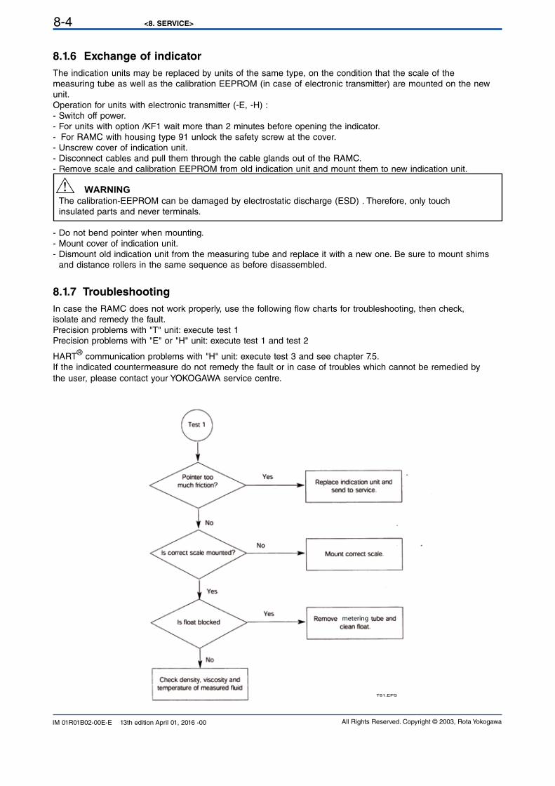
<8. SERVICE>8-4
All Rights Reserved. Copyright © 2003, Rota YokogawaIM 01R01B02-00E-E 13th edition April 01, 2016 -00
8.1.6 Exchange of indicator
The indication units may be replaced by units of the same type, on the condition that the scale of themeasuring tube as well as the calibration EEPROM (in case of electronic transmitter) are mounted on the new unit.
Operation for units with electronic transmitter (-E, -H) :
- Switch off power.- For units with option /KF1 wait more than 2 minutes before opening the indicator.- For RAMC with housing type 91 unlock the safety screw at the cover.
- Unscrew cover of indication unit.- Disconnect cables and pull them through the cable glands out of the RAMC.
- Remove scale and calibration EEPROM from old indication unit and mount them to new indication unit.
The calibration-EEPROM can be damaged by electrostatic discharge (ESD) . Therefore, only touch insulated parts and never terminals.
- Do not bend pointer when mounting.
- Mount cover of indication unit.
- Dismount old indication unit from the measuring tube and replace it with a new one. Be sure to mount shims
and distance rollers in the same sequence as before disassembled.
8.1.7 Troubleshooting
In case the RAMC does not work properly, use the following flow charts for troubleshooting, then check,isolate and remedy the fault.
Precision problems with "T" unit: execute test 1Precision problems with "E" or "H" unit: execute test 1 and test 2
HART® communication problems with "H" unit: execute test 3 and see chapter 7.5.If the indicated countermeasure do not remedy the fault or in case of troubles which cannot be remedied by
the user, please contact your YOKOGAWA service centre.
T81.EPS
metering
WARNING

<8. SERVICE> 8-5
All Rights Reserved. Copyright © 2003, Rota Yokogawa IM 01R01B02-00E-E 13th edition April 01, 2016 -00
T82.EPS
8
6
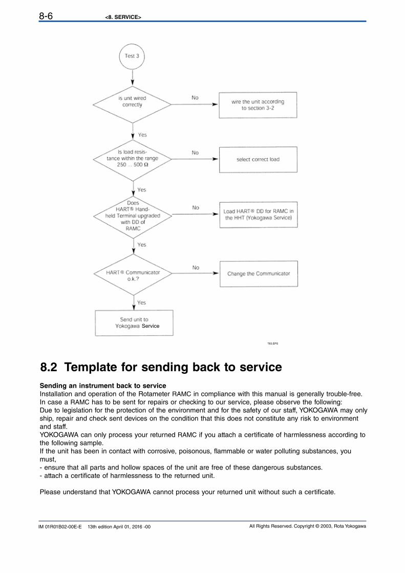
<8. SERVICE>8-6
All Rights Reserved. Copyright © 2003, Rota YokogawaIM 01R01B02-00E-E 13th edition April 01, 2016 -00
T83.EPS
Service
8.2 Template for sending back to service
Sending an instrument back to service
Installation and operation of the Rotameter RAMC in compliance with this manual is generally trouble-free.
In case a RAMC has to be sent for repairs or checking to our service, please observe the following:
Due to legislation for the protection of the environment and for the safety of our staff, YOKOGAWA may only
ship, repair and check sent devices on the condition that this does not constitute any risk to environment
and staff.
YOKOGAWA can only process your returned RAMC if you attach a certificate of harmlessness according to
the following sample.
If the unit has been in contact with corrosive, poisonous, flammable or water polluting substances, you must,
- ensure that all parts and hollow spaces of the unit are free of these dangerous substances.
- attach a certificate of harmlessness to the returned unit.
Please understand that YOKOGAWA cannot process your returned unit without such a certificate.
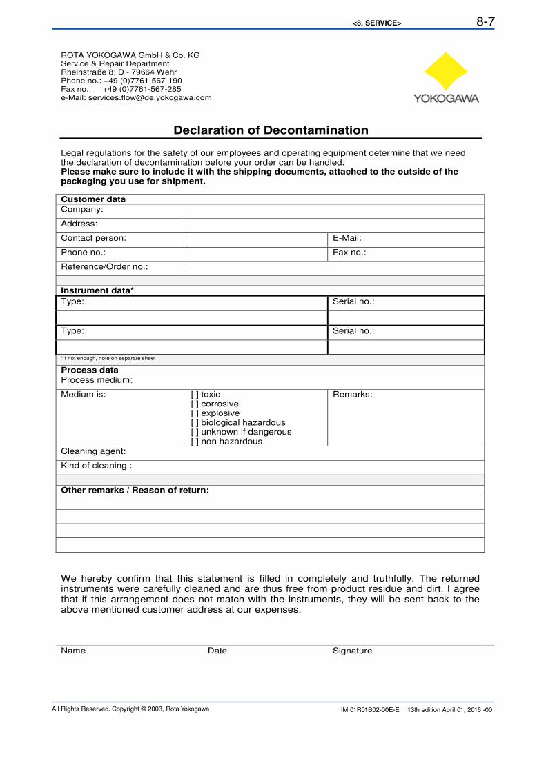
<8. SERVICE> 8-7
All Rights Reserved. Copyright © 2003, Rota Yokogawa IM 01R01B02-00E-E 13th edition April 01, 2016 -00
ROTA YOKOGAWA GmbH & Co. KG Service & Repair Department Rheinstraße 8; D - 79664 Wehr Phone no.: +49 (0)7761-567-190 Fax no.: +49 (0)7761-567-285 e-Mail: [email protected]
Declaration of Decontamination Legal regulations for the safety of our employees and operating equipment determine that we need the declaration of decontamination before your order can be handled. Please make sure to include it with the shipping documents, attached to the outside of the packaging you use for shipment.
Customer data
Company:
Address:
Contact person: E-Mail:
Phone no.: Fax no.:
Reference/Order no.:
Instrument data*
Type: Serial no.:
Type: Serial no.:
*If not enough, note on separate sheet
Process data
Process medium:
Medium is: [ ] toxic [ ] corrosive [ ] explosive [ ] biological hazardous [ ] unknown if dangerous [ ] non hazardous
Remarks:
Cleaning agent:
Kind of cleaning :
Other remarks / Reason of return:
We hereby confirm that this statement is filled in completely and truthfully. The returned instruments were carefully cleaned and are thus free from product residue and dirt. I agree that if this arrangement does not match with the instruments, they will be sent back to the above mentioned customer address at our expenses. Name Date Signature
<8. SERVICE>8-8
All Rights Reserved. Copyright © 2003, Rota YokogawaIM 01R01B02-00E-E 13th edition April 01, 2016 -00
Blank Page
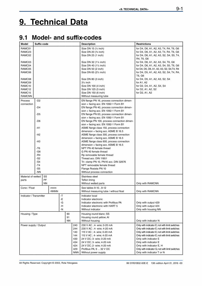
<9. TECHNICAL DATA> 9-1
All Rights Reserved. Copyright © 2003, Rota Yokogawa IM 01R01B02-00E-E 13th edition April 01, 2016 -00
9. Technical Data
9.1 Model- and suffix-codesModel Suffix code Description Restrictions
RAMC01
RAMC23
RAMC02
RAMC03
RAMC04
RAMC05RAMC06
RAMC08
RAMC09
RAMC10
RAMC12
RAMC15RAMCNN
Size DN 15 (½ inch)Size DN 20 (¾ inch)Size DN 25 (1 inch)
Size DN 32 (1¼ inch)Size DN 40 (1½ inch)Size DN 50 (2 inch)Size DN 65 (2½ inch)
Size DN 80 (3 inch)3½ inch
Size DN 100 (4 inch)Size DN 125 (5 inch)Size DN 150 (6 inch)Without measuring tube
for D4, D6, A1, A2, A3, T4, R4, T6, G6for D4, D6, A1, A2, A3, T4, R4, T6, G6for D4, D6, A1, A2, A3, S2, S4, S5, T4, R4, T6, G6for D4, D6, A1, A2, A3, S4, T6, G6for D4, D6, A1, A2, A3, S4, S5, T6, G6for D4, D5, D6, A1, A2, A3, S2, S4,T4, R4for D4, D5, A1, A2, A3, S2, S4, T4, R4, T6, G6for D4, D5, A1, A2, A3, S2, S4for A1, A2
for D2, D4, A1, A2, S4, S4for D2, A1, A2, S2for D2, A1, A2
Process connection
-D2
-D4
-D5
-D6
-A1
-A2
-A3
-T6-G6
-R4
-S2-S4-T4-S5-NN
EN flange PN 16, process connection dimen-
sion + facing acc. EN 1092-1 Form B1EN flange PN 40, process connection dimen-
sion + facing acc. EN 1092-1 Form B1EN flange PN 63, process connection dimen-
sion + facing acc. EN 1092-1 Form B1EN flange PN 100, process connection dimen-
sion + facing acc. EN 1092-1 Form B1ASME flange class 150, process connection dimension + facing acc. ASME B 16.5ASME flange class 300, process connection dimension + facing acc. ASME B 16.5ASME flange class 600, process connection dimension + facing acc. ASME B 16.5NPT PN 40 female thread G PN 40 female threadRp removable female thread
Thread acc. DIN 11851Tri- clamp PN 10, PN16 acc. DIN 32676NPT removable female threadFlange Rosista PN 10
Without process connection
Material of wetted
parts
SSPFNN
Stainless steelTeflon liningWithout wetted parts Only with RAMCNN
Cone / Float -nnnn
-NNNNSee tables 9-10...9-12
Without measuring tube / without float Only with RAMCNN
Indicator / Transmitter -T-E
-G
-H
-N
Indicator local
Indicator electronic
Indicator electronic with Profibus PAIndicator electronic with HART 5Without indicator
Only with output 429
Only with output 424
Only with housing NN
Housing / Type 90
91
NN
Housing round blanc; SSHousing round yellow; AlWithout housing Only with indicator N
Power supply / Output 240
244
140
144
430
434
424
429
NNN
230 V AC ; 4- wire; 0-20 mA230 V AC ; 4- wire; 4-20 mA115 V AC ; 4- wire; 0-20 mA115 V AC ; 4- wire; 4-20 mA24 V DC; 3- wire; 0-20 mA24 V DC; 3- wire; 4-20 mA24 V DC; 2- wire; 4-20 mAProfibus PA; 9 ... 32 V DCWithout power supply
Only with indicator E; not with limit switchesOnly with indicator E; not with limit switchesOnly with indicator E; not with limit switchesOnly with indicator E; not with limit switchesOnly with indicator E
Only with indicator E
Only with indicator E, H
Only with indicator G; not with limit switchesOnly with indicator T or N
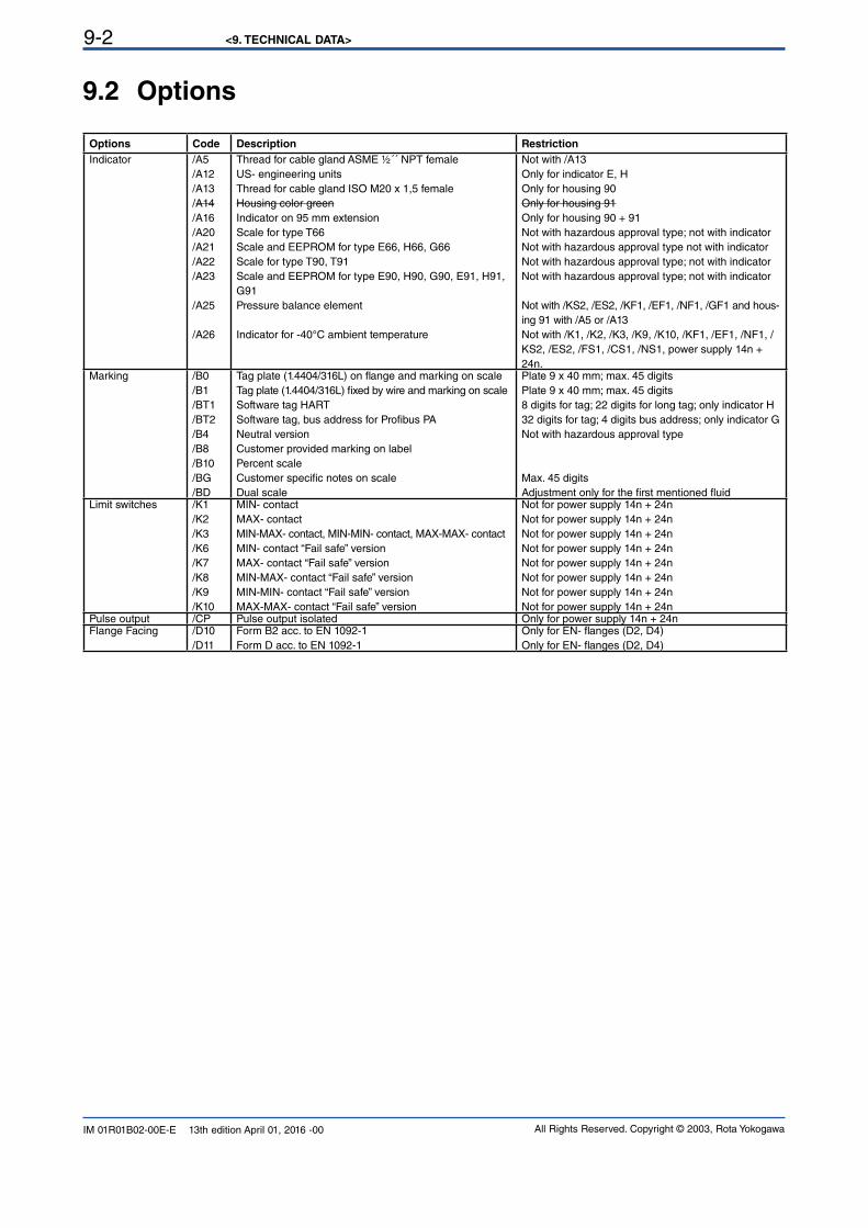
<9. TECHNICAL DATA>9-2
All Rights Reserved. Copyright © 2003, Rota YokogawaIM 01R01B02-00E-E 13th edition April 01, 2016 -00
9.2 Options
Options Code Description Restriction
Indicator /A5/A12
/A13
/A14
/A16
/A20
/A21
/A22
/A23
/A25
/A26
Thread for cable gland ASME ½´´ NPT femaleUS- engineering unitsThread for cable gland ISO M20 x 1,5 femaleHousing color green
Indicator on 95 mm extensionScale for type T66Scale and EEPROM for type E66, H66, G66Scale for type T90, T91Scale and EEPROM for type E90, H90, G90, E91, H91, G91
Pressure balance element
Indicator for -40°C ambient temperature
Not with /A13Only for indicator E, H
Only for housing 90
Only for housing 91
Only for housing 90 + 91
Not with hazardous approval type; not with indicatorNot with hazardous approval type not with indicatorNot with hazardous approval type; not with indicatorNot with hazardous approval type; not with indicator
Not with /KS2, /ES2, /KF1, /EF1, /NF1, /GF1 and hous-
ing 91 with /A5 or /A13Not with /K1, /K2, /K3, /K9, /K10, /KF1, /EF1, /NF1, /KS2, /ES2, /FS1, /CS1, /NS1, power supply 14n + 24n.
Marking /B0
/B1
/BT1/BT2/B4
/B8
/B10
/BG
/BD
Tag plate (1.4404/316L) on flange and marking on scaleTag plate (1.4404/316L) fixed by wire and marking on scaleSoftware tag HART Software tag, bus address for Profibus PANeutral versionCustomer provided marking on label
Percent scaleCustomer specific notes on scale
Dual scale
Plate 9 x 40 mm; max. 45 digitsPlate 9 x 40 mm; max. 45 digits8 digits for tag; 22 digits for long tag; only indicator H32 digits for tag; 4 digits bus address; only indicator GNot with hazardous approval type
Max. 45 digitsAdjustment only for the first mentioned fluid
Limit switches /K1
/K2
/K3
/K6
/K7
/K8
/K9
/K10
MIN- contactMAX- contact
MIN-MAX- contact, MIN-MIN- contact, MAX-MAX- contactMIN- contact “Fail safe” versionMAX- contact “Fail safe” versionMIN-MAX- contact “Fail safe” versionMIN-MIN- contact “Fail safe” versionMAX-MAX- contact “Fail safe” version
Not for power supply 14n + 24nNot for power supply 14n + 24nNot for power supply 14n + 24nNot for power supply 14n + 24nNot for power supply 14n + 24nNot for power supply 14n + 24nNot for power supply 14n + 24nNot for power supply 14n + 24n
Pulse output /CP Pulse output isolated Only for power supply 14n + 24nFlange Facing /D10
/D11
Form B2 acc. to EN 1092-1Form D acc. to EN 1092-1
Only for EN- flanges (D2, D4)Only for EN- flanges (D2, D4)
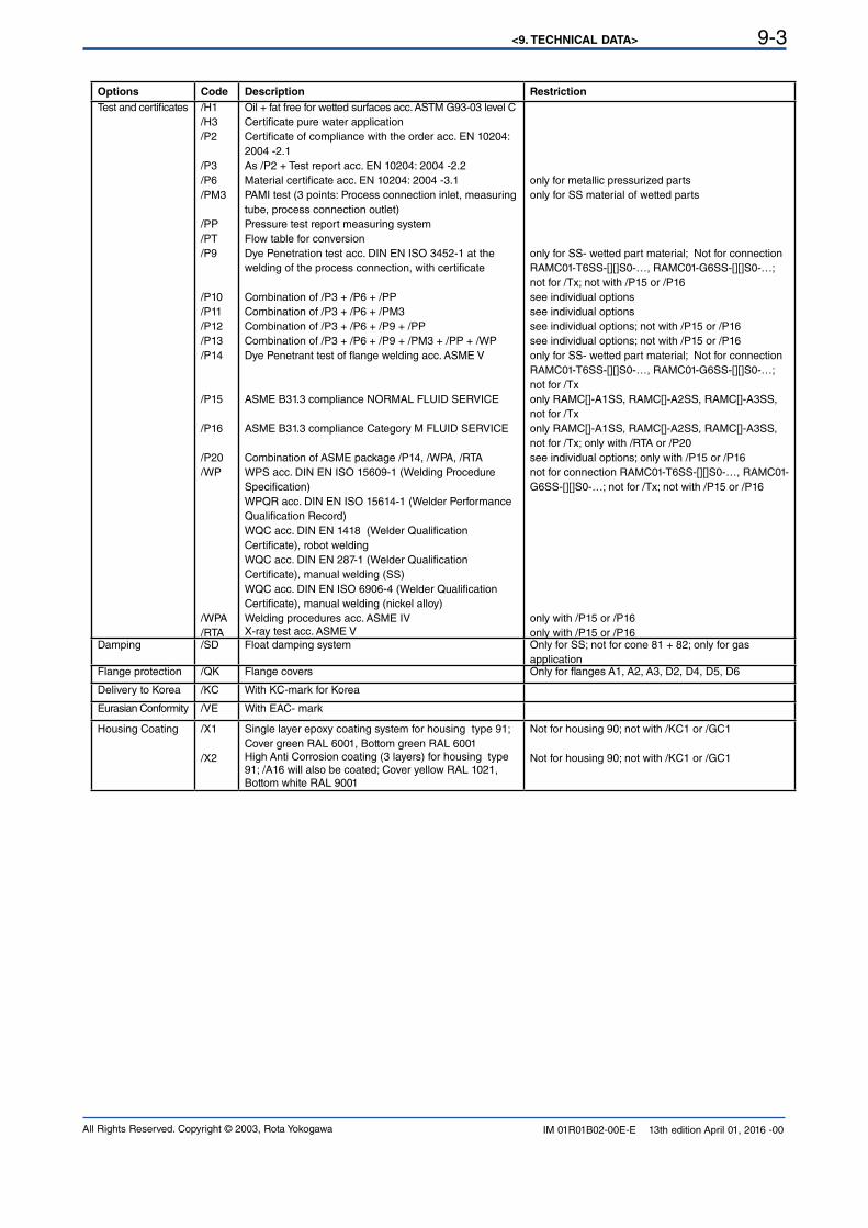
<9. TECHNICAL DATA> 9-3
All Rights Reserved. Copyright © 2003, Rota Yokogawa IM 01R01B02-00E-E 13th edition April 01, 2016 -00
Options Code Description Restriction
Test and certificates /H1
/H3
/P2
/P3/P6/PM3
/PP/PT/P9
/P10/P11/P12/P13/P14
/P15
/P16
/P20/WP
/WPA/RTA
Oil + fat free for wetted surfaces acc. ASTM G93-03 level CCertificate pure water application
Certificate of compliance with the order acc. EN 10204: 2004 -2.1
As /P2 + Test report acc. EN 10204: 2004 -2.2Material certificate acc. EN 10204: 2004 -3.1PAMI test (3 points: Process connection inlet, measuring tube, process connection outlet)
Pressure test report measuring systemFlow table for conversionDye Penetration test acc. DIN EN ISO 3452-1 at the welding of the process connection, with certificate
Combination of /P3 + /P6 + /PPCombination of /P3 + /P6 + /PM3Combination of /P3 + /P6 + /P9 + /PPCombination of /P3 + /P6 + /P9 + /PM3 + /PP + /WPDye Penetrant test of flange welding acc. ASME V
ASME B31.3 compliance NORMAL FLUID SERVICE
ASME B31.3 compliance Category M FLUID SERVICE
Combination of ASME package /P14, /WPA, /RTAWPS acc. DIN EN ISO 15609-1 (Welding Procedure Specification)WPQR acc. DIN EN ISO 15614-1 (Welder Performance Qualification Record)WQC acc. DIN EN 1418 (Welder Qualification Certificate), robot welding
WQC acc. DIN EN 287-1 (Welder Qualification Certificate), manual welding (SS)WQC acc. DIN EN ISO 6906-4 (Welder Qualification Certificate), manual welding (nickel alloy)
Welding procedures acc. ASME IVX-ray test acc. ASME V
only for metallic pressurized parts
only for SS material of wetted parts
only for SS- wetted part material; Not for connection RAMC01-T6SS-[][]S0-…, RAMC01-G6SS-[][]S0-…; not for /Tx; not with /P15 or /P16see individual options
see individual options
see individual options; not with /P15 or /P16see individual options; not with /P15 or /P16only for SS- wetted part material; Not for connection RAMC01-T6SS-[][]S0-…, RAMC01-G6SS-[][]S0-…; not for /Txonly RAMC[]-A1SS, RAMC[]-A2SS, RAMC[]-A3SS,not for /Txonly RAMC[]-A1SS, RAMC[]-A2SS, RAMC[]-A3SS,not for /Tx; only with /RTA or /P20see individual options; only with /P15 or /P16not for connection RAMC01-T6SS-[][]S0-…, RAMC01-G6SS-[][]S0-…; not for /Tx; not with /P15 or /P16
only with /P15 or /P16only with /P15 or /P16
Damping /SD Float damping system Only for SS; not for cone 81 + 82; only for gas application
Flange protection /QK Flange covers Only for flanges A1, A2, A3, D2, D4, D5, D6
Delivery to Korea /KC With KC-mark for Korea
Eurasian Conformity /VE With EAC- mark
Housing Coating /X1
/X2
Single layer epoxy coating system for housing type 91;Cover green RAL 6001, Bottom green RAL 6001High Anti Corrosion coating (3 layers) for housing type
91; /A16 will also be coated; Cover yellow RAL 1021, Bottom white RAL 9001
Not for housing 90; not with /KC1 or /GC1
Not for housing 90; not with /KC1 or /GC1
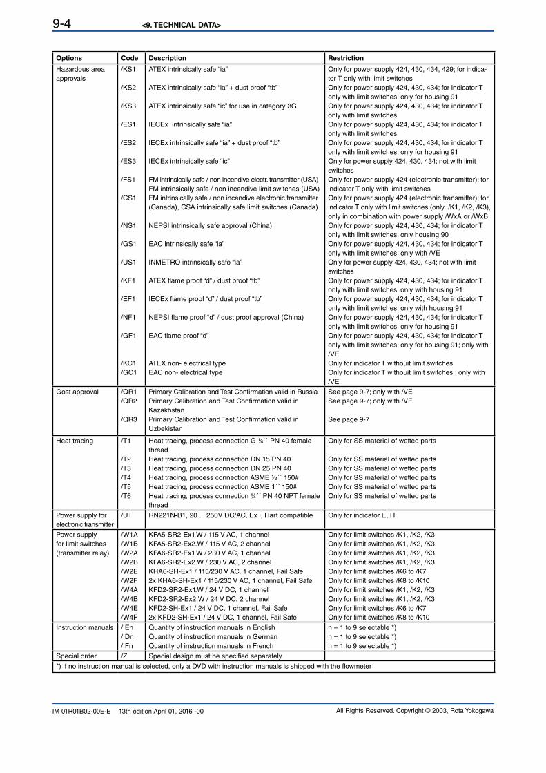
<9. TECHNICAL DATA>9-4
All Rights Reserved. Copyright © 2003, Rota YokogawaIM 01R01B02-00E-E 13th edition April 01, 2016 -00
Options Code Description Restriction
Hazardous area
approvals
/KS1
/KS2
/KS3
/ES1
/ES2
/ES3
/FS1
/CS1
/NS1
/GS1
/US1
/KF1
/EF1
/NF1
/GF1
/KC1
/GC1
ATEX intrinsically safe “ia”
ATEX intrinsically safe “ia” + dust proof “tb”
ATEX intrinsically safe “ic” for use in category 3G
IECEx intrinsically safe “ia”
IECEx intrinsically safe “ia” + dust proof “tb”
IECEx intrinsically safe “ic”
FM intrinsically safe / non incendive electr. transmitter (USA)FM intrinsically safe / non incendive limit switches (USA)FM intrinsically safe / non incendive electronic transmitter (Canada), CSA intrinsically safe limit switches (Canada)
NEPSI intrinsically safe approval (China)
EAC intrinsically safe “ia”
INMETRO intrinsically safe “ia”
ATEX flame proof “d” / dust proof “tb”
IECEx flame proof “d” / dust proof “tb”
NEPSI flame proof “d” / dust proof approval (China)
EAC flame proof “d”
ATEX non- electrical typeEAC non- electrical type
Only for power supply 424, 430, 434, 429; for indica-
tor T only with limit switchesOnly for power supply 424, 430, 434; for indicator T only with limit switches; only for housing 91Only for power supply 424, 430, 434; for indicator T only with limit switches
Only for power supply 424, 430, 434; for indicator T only with limit switches
Only for power supply 424, 430, 434; for indicator T only with limit switches; only for housing 91Only for power supply 424, 430, 434; not with limit switches
Only for power supply 424 (electronic transmitter); for indicator T only with limit switchesOnly for power supply 424 (electronic transmitter); for indicator T only with limit switches (only /K1, /K2, /K3), only in combination with power supply /WxA or /WxBOnly for power supply 424, 430, 434; for indicator T only with limit switches; only housing 90Only for power supply 424, 430, 434; for indicator T only with limit switches; only with /VEOnly for power supply 424, 430, 434; not with limit switches
Only for power supply 424, 430, 434; for indicator T only with limit switches; only with housing 91Only for power supply 424, 430, 434; for indicator T only with limit switches; only with housing 91Only for power supply 424, 430, 434; for indicator T only with limit switches; only for housing 91Only for power supply 424, 430, 434; for indicator T only with limit switches; only for housing 91; only with /VEOnly for indicator T withouit limit switchesOnly for indicator T withouit limit switches ; only with /VE
Gost approval /QR1/QR2
/QR3
Primary Calibration and Test Confirmation valid in Russia Primary Calibration and Test Confirmation valid in Kazakhstan
Primary Calibration and Test Confirmation valid in Uzbekistan
See page 9-7; only with /VESee page 9-7; only with /VE
See page 9-7
Heat tracing /T1
/T2/T3/T4/T5/T6
Heat tracing, process connection G ¼`` PN 40 female thread
Heat tracing, process connection DN 15 PN 40Heat tracing, process connection DN 25 PN 40Heat tracing, process connection ASME ½´´ 150#Heat tracing, process connection ASME 1´´ 150#Heat tracing, process connection ¼´´ PN 40 NPT female thread
Only for SS material of wetted parts
Only for SS material of wetted partsOnly for SS material of wetted partsOnly for SS material of wetted partsOnly for SS material of wetted partsOnly for SS material of wetted parts
Power supply forelectronic transmitter
/UT RN221N-B1, 20 ... 250V DC/AC, Ex i, Hart compatible Only for indicator E, H
Power supply for limit switches
(transmitter relay)
/W1A
/W1B
/W2A
/W2B
/W2E
/W2F/W4A
/W4B
/W4E
/W4F
KFA5-SR2-Ex1.W / 115 V AC, 1 channelKFA5-SR2-Ex2.W / 115 V AC, 2 channelKFA6-SR2-Ex1.W / 230 V AC, 1 channelKFA6-SR2-Ex2.W / 230 V AC, 2 channelKHA6-SH-Ex1 / 115/230 V AC, 1 channel, Fail Safe2x KHA6-SH-Ex1 / 115/230 V AC, 1 channel, Fail SafeKFD2-SR2-Ex1.W / 24 V DC, 1 channelKFD2-SR2-Ex2.W / 24 V DC, 2 channelKFD2-SH-Ex1 / 24 V DC, 1 channel, Fail Safe2x KFD2-SH-Ex1 / 24 V DC, 1 channel, Fail Safe
Only for limit switches /K1, /K2, /K3
Only for limit switches /K1, /K2, /K3
Only for limit switches /K1, /K2, /K3
Only for limit switches /K1, /K2, /K3
Only for limit switches /K6 to /K7
Only for limit switches /K8 to /K10
Only for limit switches /K1, /K2, /K3
Only for limit switches /K1, /K2, /K3
Only for limit switches /K6 to /K7
Only for limit switches /K8 to /K10
Instruction manuals /IEn
/IDn
/IFn
Quantity of instruction manuals in EnglishQuantity of instruction manuals in GermanQuantity of instruction manuals in French
n = 1 to 9 selectable *)
n = 1 to 9 selectable *)
n = 1 to 9 selectable *)
Special order /Z Special design must be specified separately
*) if no instruction manual is selected, only a DVD with instruction manuals is shipped with the flowmeter
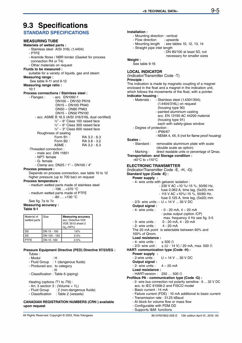
<9. TECHNICAL DATA> 9-5
All Rights Reserved. Copyright © 2003, Rota Yokogawa IM 01R01B02-00E-E 13th edition April 01, 2016 -00
9.3 SpecificationsSTANDARD SPECIFICATIONS
MEASURING TUBEMaterials of wetted parts : - Stainless steel AISI 316L (1.4404) - PTFE - Aramide fibres / NBR binder (Gasket for process connection R4 or T4) - Other materials on requestFluids to be measured : suitable for a variety of liquids, gas and steamMeasuring range : See table 9-11 and 9-12Measuring range ratio : 10:1Process connections / Stainless steel : - Flanges : - acc. EN1092-1 DN100 – DN150 PN16 DN15 – DN100 PN40 DN50 – DN80 PN63 DN15 – DN50 PN100 - acc. ASME B 16.5 (AISI 316/316L dual certified) ½” – 6“ Class 150 raised face ½” – 6“ Class 300 raised face ½” – 3“ Class 600 raised face Roughness of sealing Form B1 : RA 3.2 - 6.3 Form B2 : RA 0.8 - 3.2 ASME : RA 3.2 - 6.3 -Threaded connection : - male acc. DIN 11851 - NPT- female - G- female - Clamp acc. DN25 / 1“ – DN100 / 4“Process pressure : Depends on process connection, see table 10 to 12 higher pressure (up to 700 bar) on request Process temperature : - medium wetted parts made of stainless steel : -196 …+370 °C - medium wetted parts made of PTFE : -80 … +130 °C See fig. 7a to 7cMeasuring accuracy : Table 9-1
Material of
wetted parts
Size Measuring accuracy
acc. Directive VDI/VDE 3513 sheet 2 (q
G=50%)
SS DN 15 - 100 1.6%
SS DN 125 - 150 2.5%
PTFE DN 15 -100 2.5%
Pressure Equipment Directive (PED) Directive 97/23/EG : Tubes : - Modul : H - Fluid Group : 1 (dangerous fluids) - Produced acc. to category : III - Classification : Table 6 (piping) Heating (options /T1 to /T6) : - Art. 3 section 3 : (Volume < 1L) - Fluid Group : 2 (non-dangerous fluids) - Classification : Table 2 (vessels)
CANADIAN REGISTRATION NUMBERS (CRN ) available upon request
Installation : - Mounting direction : vertical - Flow direction : upwards - Mounting length : see tables 10, 12, 13, 14 - Straight pipe inlet length : DN 80/100 at least 5D, not necessary for smaller sizesWeight : See table 9-16
LOCAL INDICATOR(Indicator/Transmitter Code -T)Principle : The indication is made by magnetic coupling of a magnet enclosed in the float and a magnet in the indication unit, which follows the movements of the float, with a pointer.Indicator housing : - Materials : - Stainless steel (1.4301/304); (1.4404/316L) on request (housing type 90) - painted aluminium casting acc. EN 13195 AC 44200 material (housing type 91) each with safety-glass window - Degree of protection : - IP66/67 - NEMA 4, 4X, 6 (not for flame proof housing)Scales : - Standard : removable aluminium plate with scale (double scale as option) - Marking : direct readable units or percentage of Qmax.Transportation- and Storage condition : -40°C to +110°C
ELECTRONIC TRANSMITTER(Indicator/Transmitter Code -E, -H, -G)Standard type (Code -E) : Power supply : - 4- wire units with galvanic isolation : - 230 V AC +10 %/-15 %, 50/60 Hz, fuse 0.063 A, time lag, (5x20) mm - 115 V AC +10%/-15 %, 50/60 Hz, fuse 0.125 A, time lag, (5x20) mm - 2/3- wire units : - U = 14 V ... 30 V DC Output signal : - 4- wire units : - 0 - 20 mA, 4 – 20 mA - pulse output (option /CP) max. frequency 4 Hz see fig. 3-5 - 3- wire units : 0 - 20 mA, 4 - 20 mA - 2- wire units : 4 - 20 mA The 20 mA point is selectable between 60% and 100% of Qnom. Load resistance : - 4- wire units : ≤ 500 Ω - 2/3- wire unit : ≤ (U - 14 V) / 20 mA, max. 500 ΩHART- communication type (Code -H) : Power supply : - 2-wire units : U = 14 V ... 30 V DC Output signal : - 2- wire units : 4 – 20 mA Load resistance : - HART-version : 250 … 500 ΩProfibus PA - communication type (Code -G) : - 2- wire bus connection not polarity sensitive : 9 ... 32 V DC acc. to IEC 61568-2 and FISCO model - Basic current : 14 mA - Failure current (FDE) : 10 mA additional to basic current - Transmission rate : 31.25 kBaud - AI block for volume flow or mass flow - Configurable with PDM DD - Supports I&M- functions
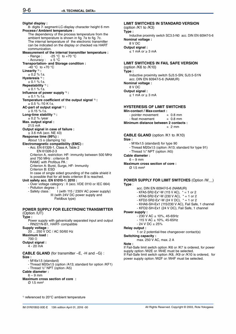
<9. TECHNICAL DATA>9-6
All Rights Reserved. Copyright © 2003, Rota YokogawaIM 01R01B02-00E-E 13th edition April 01, 2016 -00
LIMIT SWITCHES IN STANDARD VERSION (option /K1 to /K3)Type : Inductive proximity switch SC3.5-N0 acc. DIN EN 60947-5-6 Nominal voltage : 8 V DCOutput signal : ≤ 1 mA or ≥ 3 mA
LIMIT SWITCHES IN FAIL SAFE VERSION (option /K6 to /K10)Type : Inductive proximity switch SJ3.5-SN; SJ3.5-S1N acc. DIN EN 60947-5-6 (NAMUR)Nominal voltage : 8 V DCOutput signal : ≤ 1 mA or ≥ 3 mA
HYSTERESIS OF LIMIT SWITCHESMin-contact / Max-contact : - pointer movement ≈ 0.8 mm - float movement ≈ 0.8 mmMinimum distance between 2 contacts : ≈ 2 mm
CABLE GLAND (option /K1 to /K10)Size :
- M16x1.5 (standard) for type 90 - Thread M20x1.5 (option /A13; standard for type 91) - Thread ½” NPT (option /A5)Cable diameter :
6 – 9 mmMaximum cross section of core :
Ø 1.5 mm²
POWER SUPPLY FOR LIMIT SWITCHES (Option /W__) Type : acc. DIN EN 60947-5-6 (NAMUR) - KFA5-SR2-Ex*-W (115 V AC), * = 1 or 2 - KFA6-SR2-Ex*-W (230 V AC), * = 1 or 2 - KFD2-SR2-Ex*-W (24 V DC), * = 1 or 2 - KHA6-SH-Ex1 (115/230 V AC), Fail Safe, 1 channel - KFD2-SH-Ex1 (24 V DC), Fail Safe, 1 channel Power supply : - 230 V AC ± 10%, 45-65Hz - 115 V AC ± 10%, 45-65Hz - 24 V DC ± 25%Relay output : 1 or 2 potential-free changeover contact(s) Switching capacity : max. 250 V AC, max. 2 ANote :If Fail-Safe limit switch option /K6 or /K7 is ordered, for power supply option /W2E or /W4E must be selected.If Fail-Safe limit switch option /K8, /K9 or /K10 is ordered, for power supply option /W2F or /W4F must be selected.
1) referenced to 20°C ambient temperature
Digital display : 8- digits 7- segment-LC-display character height 6 mmProcess-/ Ambient temperature : The dependency of the process temperature from the ambient temperature is shown in fig. 7a to fig. 7c. The internal temperature of the electronic transmitter can be indicated on the display or checked via HART communication.Measurement of the internal transmitter temperature : - Range : -25 °C to +70 °C - Accuracy : ± 5 °CTransportation- and Storage condition : -40 °C to +70 °CLinearity 1) : ± 0.2 % f.s.Hysteresis 1) : ± 0.1 % f.s.Repeatability 1) : ± 0.1 % f.s.Influence of power supply 1) : ± 0.1 % f.s.Temperature coefficient of the output signal 1) : ± 0.5 % /10 K f.s.AC-part of output signal 1) : ± 0.15 % f.s.Long-time stability 1) : ± 0.2 % /yearMax. output signal : 21.5 mAOutput signal in case of failure : ≤ 3.6 mA (acc. NE 43)Response time (99%) : About 1.5 s (damping 1s)Electromagnetic compatibility (EMC) : - Acc. EN 61326-1, Class A, Table 2 EN 61326-2-3 Criterion A, restriction: HF- immunity between 500 MHz and 750 MHz : criterion B RAMC with Profibus PA : Criterion A: Burst, Surge, HF- Immunity Criterion B: ESD In case of single sided grounding of the cable shield it is possible that for all tests criterion B is reached.Unit safety acc. EN 61010-1: 2010 : - Over voltage category : II (acc. VDE 0110 or IEC 664) - Pollution degree : I - Safety class : I (with 115 / 230V AC power supply) III (with 24V DC power supply and Fieldbus type)
POWER SUPPLY FOR ELECTRONIC TRANSMITTER (Option /UT)Type : Power supply with galvanically separated input and output - RN221N-B1, HART- compatibleSupply voltage : 20 ... 250 V DC / AC 50/60 Hz Maximum load : 700 ΩOutput signal : 4 - 20 mA
CABLE GLAND (for transmitter –E, -H and –G) :Size : - M16x1.5 (standard) - Thread M20x1.5 (option /A13; standard for option /KF1) - Thread ½” NPT (option /A5)Cable diameter : 6 – 9 mmMaximum cross section of core : Ø 1.5 mm²
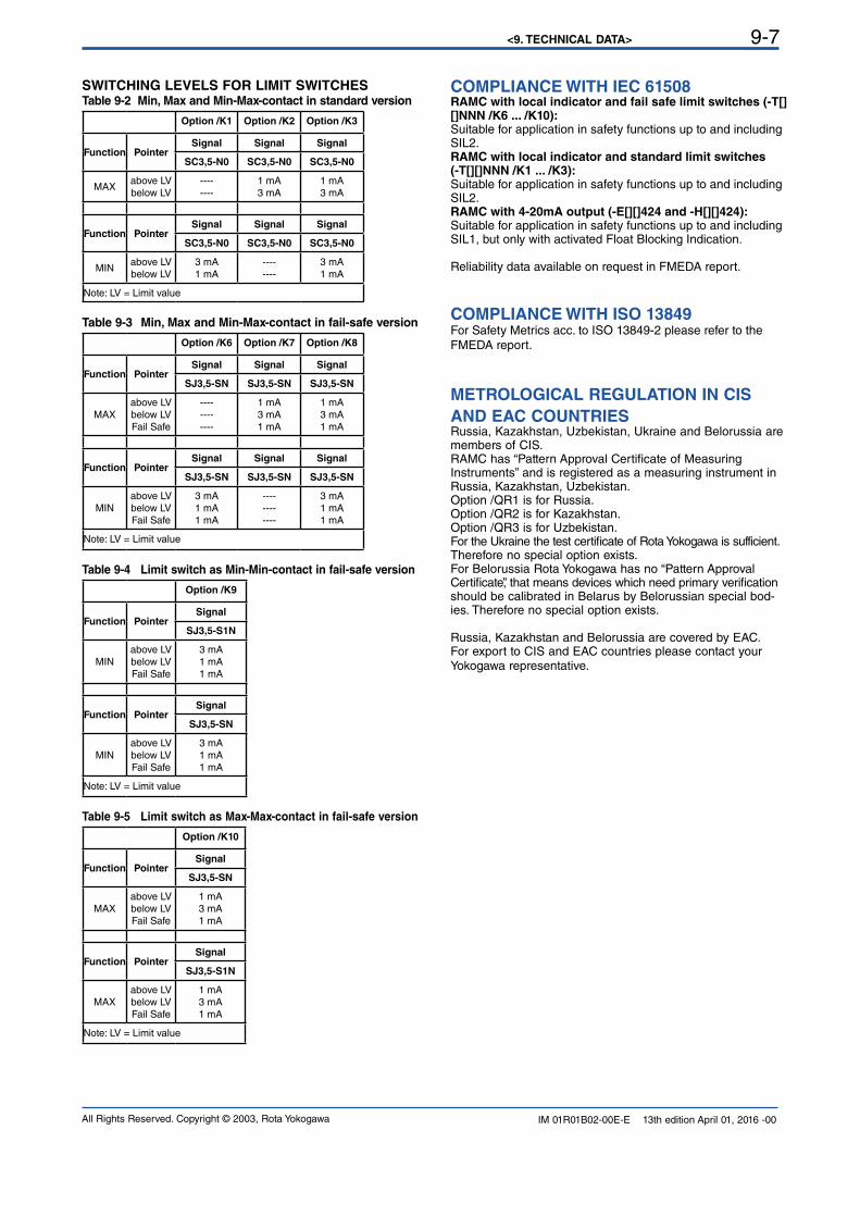
<9. TECHNICAL DATA> 9-7
All Rights Reserved. Copyright © 2003, Rota Yokogawa IM 01R01B02-00E-E 13th edition April 01, 2016 -00
COMPLIANCE WITH IEC 61508RAMC with local indicator and fail safe limit switches (-T[][]NNN /K6 ... /K10):Suitable for application in safety functions up to and including SIL2.RAMC with local indicator and standard limit switches (-T[][]NNN /K1 ... /K3):Suitable for application in safety functions up to and including SIL2.RAMC with 4-20mA output (-E[][]424 and -H[][]424):Suitable for application in safety functions up to and including SIL1, but only with activated Float Blocking Indication.
Reliability data available on request in FMEDA report.
COMPLIANCE WITH ISO 13849For Safety Metrics acc. to ISO 13849-2 please refer to the FMEDA report.
METROLOGICAL REGULATION IN CIS
AND EAC COUNTRIESRussia, Kazakhstan, Uzbekistan, Ukraine and Belorussia are members of CIS.RAMC has “Pattern Approval Certificate of Measuring Instruments” and is registered as a measuring instrument in Russia, Kazakhstan, Uzbekistan. Option /QR1 is for Russia.Option /QR2 is for Kazakhstan.Option /QR3 is for Uzbekistan.For the Ukraine the test certificate of Rota Yokogawa is sufficient. Therefore no special option exists. For Belorussia Rota Yokogawa has no “Pattern Approval Certificate”, that means devices which need primary verification should be calibrated in Belarus by Belorussian special bod-ies. Therefore no special option exists.
Russia, Kazakhstan and Belorussia are covered by EAC.For export to CIS and EAC countries please contact your Yokogawa representative.
SWITCHING LEVELS FOR LIMIT SWITCHES Table 9-2 Min, Max and Min-Max-contact in standard version
Option /K1 Option /K2 Option /K3
Function PointerSignal Signal Signal
SC3,5-N0 SC3,5-N0 SC3,5-N0
MAXabove LV below LV
----
----
1 mA
3 mA
1 mA
3 mA
Function PointerSignal Signal Signal
SC3,5-N0 SC3,5-N0 SC3,5-N0
MINabove LV below LV
3 mA
1 mA
----
----
3 mA
1 mA
Note: LV = Limit value
Table 9-3 Min, Max and Min-Max-contact in fail-safe version
Option /K6 Option /K7 Option /K8
Function PointerSignal Signal Signal
SJ3,5-SN SJ3,5-SN SJ3,5-SN
MAX
above LV below LVFail Safe
----
----
----
1 mA
3 mA
1 mA
1 mA
3 mA
1 mA
Function PointerSignal Signal Signal
SJ3,5-SN SJ3,5-SN SJ3,5-SN
MINabove LV below LVFail Safe
3 mA
1 mA
1 mA
----
----
----
3 mA
1 mA
1 mA
Note: LV = Limit value
Table 9-4 Limit switch as Min-Min-contact in fail-safe version
Option /K9
Function PointerSignal
SJ3,5-S1N
MINabove LV below LVFail Safe
3 mA
1 mA
1 mA
Function PointerSignal
SJ3,5-SN
MINabove LV below LVFail Safe
3 mA
1 mA
1 mA
Note: LV = Limit value
Table 9-5 Limit switch as Max-Max-contact in fail-safe version
Option /K10
Function PointerSignal
SJ3,5-SN
MAX
above LV below LVFail Safe
1 mA
3 mA
1 mA
Function PointerSignal
SJ3,5-S1N
MAX
above LV below LVFail Safe
1 mA
3 mA
1 mA
Note: LV = Limit value
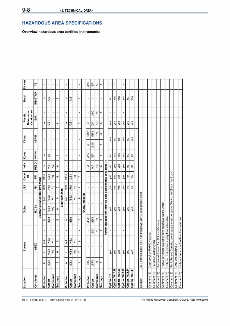
<9. TECHNICAL DATA>9-8
All Rights Reserved. Copyright © 2003, Rota YokogawaIM 01R01B02-00E-E 13th edition April 01, 2016 -00
Lo
cati
on
Eu
rop
eG
lob
al
US
AC
an
a-
da
Ind
ia
Ko
rea
Ch
ina
Ru
ss
ia,
Be
loru
ss
ia,
Ka
za
kh
sta
n
Bra
zil
Ta
iwa
n
Cert
ificate
AT
EX
IEC
Ex
FM
FM
PE
SO
KO
SH
AN
EP
SI
EA
CIN
ME
TR
OT
S
Ele
ctr
on
ic t
ran
sm
itte
r (W
T-M
AG
)
Pro
tectio
nia
icia
/tb
-ia
icia
/tb
IS/N
lIS
/Nl
iaia
-ia
-ia
-
Op
tio
n/K
S1
/KS
3/K
S2
-/E
S1
/ES
3/E
S2
/FS
1/C
S1
/KS
1/E
S1
-/G
S1
-/U
S1
-
Co
mm
en
ts*2
)*1
)-
-*2
)*1
)*3
)*3
)*4
)-
--
-
See p
ag
e6
69
-6
69
66
66
-6
-6
-
Lim
it s
wit
ch
es
Pro
tectio
nia
icia
/tb
-ia
-ia
/tb
IS/N
lIS
/Nl
--
-ia
-ia
-
Op
tio
n/K
S1
/KS
3/K
S2
-/E
S1
-/E
S2
/FS
1/C
S1
--
-/G
S1
-/U
S1
-
Co
mm
en
ts*2
)*1
)-
--
*1)
*5)
*6)
--
--
--
See p
ag
e7
79
-7
-9
77
--
-7
-7
-
RA
MC
in
dic
ato
r
Pro
tectio
nd/tb
--
db/t
b-
--
dd/t
bia
d/D
IPd
--
d/tb
Op
tio
n/K
F1
-/K
C1
/EF
1-
--
/KF
1/E
F1
/NS
1/N
F1
/GF
1/G
C1
-/E
F1
Co
mm
en
ts*7
)-
*8)
*7)
--
-*4
)*7
)*7
)*8
)-
*7)
See p
ag
e8
-9
8-
--
88
88
89
-8
Po
wer
su
pp
lies f
or
intr
insic
safe
co
mp
on
en
ts (
see p
ag
e 7
)
Op
tio
n /U
Tyes
-yes
yes
yes
no
no
yes
yes
-n
o-
Op
tio
n /W
1A
,Byes
-yes
yes
yes
yes
yes
no
yes
-yes
-
Op
tio
n /W
2A
,Byes
-yes
yes
yes
yes
yes
no
yes
-yes
-
Op
tio
n /W
4A
,Byes
-yes
yes
yes
yes
yes
yes
yes
-yes
-
Op
tio
n /W
2E
,Fyes
-yes
no
no
no
no
no
yes
-n
o-
Op
tio
n /W
4E
,Fyes
-yes
no
no
no
no
yes
yes
-yes
-
Not
atio
nIS
= in
trin
sic
safe
; N
l = n
on in
cend
ive;
DIP
= d
ust i
gniti
on p
roof
Com
ment *1
)D
ust pro
of by R
AM
C h
ousin
g
Com
ment *2
)F
or u
se in
cat
egor
y 3G
Com
ment *3
)S
ame
cert
ifica
tion
for
US
A a
nd C
anad
a
Com
ment *4
)P
ES
O c
ertifi
cate
ava
ilabl
e fr
om Y
okog
awa
Sal
es O
ffice
Com
men
t *5)
Onl
y fo
r U
SA
; pow
er s
uppl
y fr
ee s
elec
tabl
e
Com
ment *6
)F
or U
SA
and
Can
ada;
pow
er s
uppl
y m
ust b
e op
tion
/WxA
or
/WxB
(x=
1 or
2 o
r 4)
Com
ment *7
)O
nly
with h
ousin
g 9
1
Com
ment *8
)O
nly
indi
cato
r ty
pe T
with
out l
imit
switc
hes
HAZARDOUS AREA SPECIFICATIONS
Overview hazardous area certified instruments:
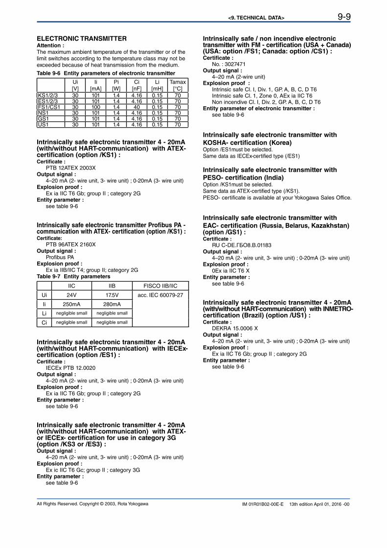
<9. TECHNICAL DATA> 9-9
All Rights Reserved. Copyright © 2003, Rota Yokogawa IM 01R01B02-00E-E 13th edition April 01, 2016 -00
ELECTRONIC TRANSMITTERAttention :The maximum ambient temperature of the transmitter or of the limit switches according to the temperature class may not be exceeded because of heat transmission from the medium.
Table 9-6 Entity parameters of electronic transmitter
Ui[V]
Ii
[mA]Pi
[W]Ci
[nF]Li
[mH]Tamax
[°C]KS1/2/3 30 101 1.4 4.16 0.15 70ES1/2/3 30 101 1.4 4.16 0.15 70FS1/CS1 30 100 1.4 40 0.15 70NS1 30 101 1.4 4.16 0.15 70GS1 30 101 1.4 4.16 0.15 70US1 30 101 1.4 4.16 0.15 70
Intrinsically safe electronic transmitter 4 - 20mA (with/without HART-communication) with ATEX- certification (option /KS1) :Certificate : PTB 12ATEX 2003XOutput signal : 4–20 mA (2- wire unit, 3- wire unit) ; 0-20mA (3- wire unit)Explosion proof : Ex ia IIC T6 Gb; group II ; category 2GEntity parameter : see table 9-6
Intrinsically safe electronic transmitter Profibus PA -communication with ATEX- certification (option /KS1) :Certificate: PTB 96ATEX 2160XOutput signal : Profibus PAExplosion proof : Ex ia IIB/IIC T4; group II; category 2GTable 9-7 Entity parameters
IIC IIB FISCO IIB/IIC
Ui 24V 17.5V acc. IEC 60079-27
Ii 250mA 280mA
Li negligible small negligible small
Ci negligible small negligible small
Intrinsically safe electronic transmitter 4 - 20mA (with/without HART-communication) with IECEx- certification (option /ES1) :Certificate : IECEx PTB 12.0020Output signal : 4–20 mA (2- wire unit, 3- wire unit) ; 0-20mA (3- wire unit)Explosion proof : Ex ia IIC T6 Gb; group II ; category 2G Entity parameter : see table 9-6
Intrinsically safe electronic transmitter 4 - 20mA (with/without HART-communication) with ATEX- or IECEx- certification for use in category 3G (option /KS3 or /ES3) :Output signal : 4–20 mA (2- wire unit, 3- wire unit) ; 0-20mA (3- wire unit)Explosion proof : Ex ic IIC T6 Gc; group II ; category 3G Entity parameter : see table 9-6
Intrinsically safe / non incendive electronic transmitter with FM - certification (USA + Canada) (USA: option /FS1; Canada: option /CS1) :Certificate : No. : 3027471Output signal : 4–20 mA (2-wire unit)Explosion proof : Intrinsic safe Cl. I, Div. 1, GP. A, B, C, D T6 Intrinsic safe Cl. 1, Zone 0, AEx ia IIC T6 Non incendive Cl. I, Div. 2, GP. A, B, C, D T6 Entity parameter of electronic transmitter : see table 9-6
Intrinsically safe electronic transmitter with
KOSHA- certification (Korea) Option /ES1must be selected.Same data as IECEx-certified type (/ES1)
Intrinsically safe electronic transmitter with
PESO- certification (India) Option /KS1must be selected.Same data as ATEX-certified type (/KS1).PESO- certificate is available at your Yokogawa Sales Office.
Intrinsically safe electronic transmitter with
EAC- certification (Russia, Belarus, Kazakhstan) (option /GS1) :Certificate : RU С-DЕ.ГБО8.В.01183Output signal : 4–20 mA (2- wire unit, 3- wire unit) ; 0-20mA (3- wire unit)Explosion proof : 0Ex ia IIC T6 XEntity parameter : see table 9-6
Intrinsically safe electronic transmitter 4 - 20mA (with/without HART-communication) with INMETRO- certification (Brazil) (option /US1) :Certificate : DEKRA 15.0006 XOutput signal : 4–20 mA (2- wire unit, 3- wire unit) ; 0-20mA (3- wire unit)Explosion proof : Ex ia IIC T6 Gb; group II ; category 2G Entity parameter : see table 9-6
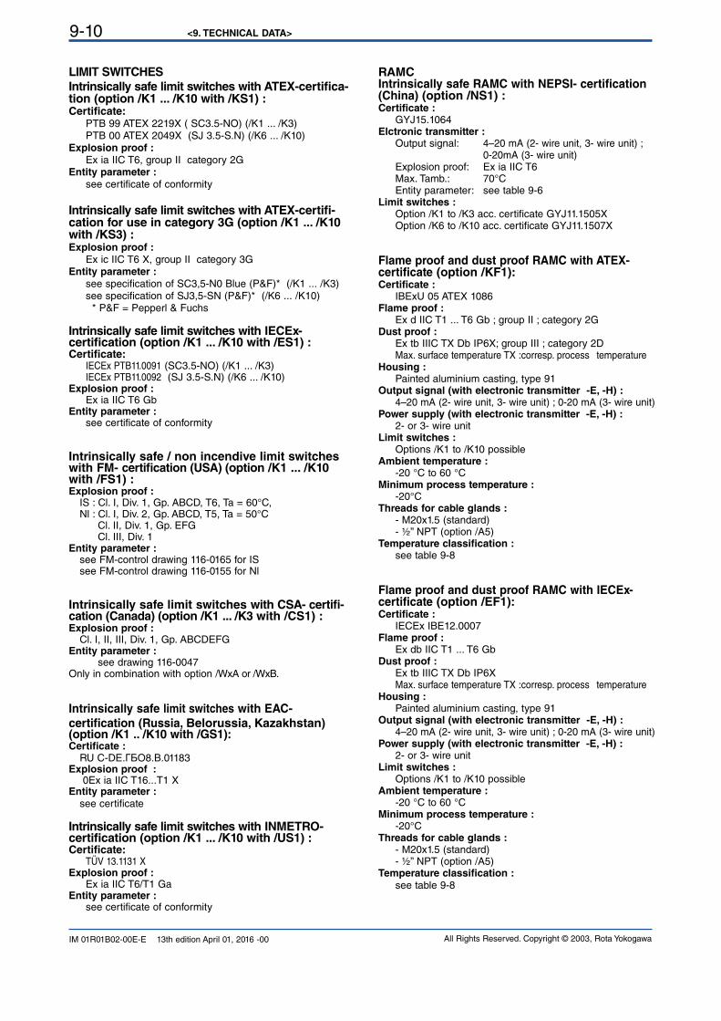
<9. TECHNICAL DATA>9-10
All Rights Reserved. Copyright © 2003, Rota YokogawaIM 01R01B02-00E-E 13th edition April 01, 2016 -00
LIMIT SWITCHES
Intrinsically safe limit switches with ATEX-certifica-tion (option /K1 ... /K10 with /KS1) :Certificate: PTB 99 ATEX 2219X ( SC3.5-NO) (/K1 ... /K3) PTB 00 ATEX 2049X (SJ 3.5-S.N) (/K6 ... /K10)Explosion proof : Ex ia IIC T6, group II category 2GEntity parameter : see certificate of conformity
Intrinsically safe limit switches with ATEX-certifi-cation for use in category 3G (option /K1 ... /K10 with /KS3) : Explosion proof : Ex ic IIC T6 X, group II category 3GEntity parameter : see specification of SC3,5-N0 Blue (P&F)* (/K1 ... /K3) see specification of SJ3,5-SN (P&F)* (/K6 ... /K10) * P&F = Pepperl & Fuchs
Intrinsically safe limit switches with IECEx-certification (option /K1 ... /K10 with /ES1) :Certificate: IECEx PTB11.0091 (SC3.5-NO) (/K1 ... /K3) IECEx PTB11.0092 (SJ 3.5-S.N) (/K6 ... /K10) Explosion proof : Ex ia IIC T6 GbEntity parameter : see certificate of conformity
Intrinsically safe / non incendive limit switches with FM- certification (USA) (option /K1 ... /K10 with /FS1) :Explosion proof : IS : Cl. I, Div. 1, Gp. ABCD, T6, Ta = 60°C, Nl : Cl. I, Div. 2, Gp. ABCD, T5, Ta = 50°C Cl. II, Div. 1, Gp. EFG Cl. III, Div. 1Entity parameter : see FM-control drawing 116-0165 for IS see FM-control drawing 116-0155 for Nl
Intrinsically safe limit switches with CSA- certifi-cation (Canada) (option /K1 ... /K3 with /CS1) :Explosion proof : Cl. I, II, III, Div. 1, Gp. ABCDEFG Entity parameter : see drawing 116-0047Only in combination with option /WxA or /WxB.
Intrinsically safe limit switches with EAC-
certification (Russia, Belorussia, Kazakhstan) (option /K1 .. /K10 with /GS1):Certificate : RU С-DЕ.ГБО8.В.01183Explosion proof : 0Ex ia IIC T16...T1 XEntity parameter : see certificate
Intrinsically safe limit switches with INMETRO-certification (option /K1 ... /K10 with /US1) :Certificate: TÜV 13.1131 XExplosion proof : Ex ia IIC T6/T1 GaEntity parameter : see certificate of conformity
RAMCIntrinsically safe RAMC with NEPSI- certification (China) (option /NS1) :Certificate : GYJ15.1064Elctronic transmitter : Output signal: 4–20 mA (2- wire unit, 3- wire unit) ; 0-20mA (3- wire unit) Explosion proof: Ex ia IIC T6 Max. Tamb.: 70°C Entity parameter: see table 9-6Limit switches : Option /K1 to /K3 acc. certificate GYJ11.1505X Option /K6 to /K10 acc. certificate GYJ11.1507X
Flame proof and dust proof RAMC with ATEX- certificate (option /KF1):Certificate : IBExU 05 ATEX 1086Flame proof : Ex d IIC T1 ... T6 Gb ; group II ; category 2GDust proof : Ex tb IIIC TX Db IP6X; group III ; category 2D Max. surface temperature TX :corresp. process temperature Housing : Painted aluminium casting, type 91Output signal (with electronic transmitter -E, -H) : 4–20 mA (2- wire unit, 3- wire unit) ; 0-20 mA (3- wire unit)Power supply (with electronic transmitter -E, -H) : 2- or 3- wire unitLimit switches : Options /K1 to /K10 possibleAmbient temperature : -20 °C to 60 °C Minimum process temperature : -20°CThreads for cable glands : - M20x1.5 (standard) - ½” NPT (option /A5)Temperature classification : see table 9-8
Flame proof and dust proof RAMC with IECEx- certificate (option /EF1):Certificate : IECEx IBE12.0007 Flame proof : Ex db IIC T1 ... T6 GbDust proof : Ex tb IIIC TX Db IP6X Max. surface temperature TX :corresp. process temperature Housing : Painted aluminium casting, type 91Output signal (with electronic transmitter -E, -H) : 4–20 mA (2- wire unit, 3- wire unit) ; 0-20 mA (3- wire unit)Power supply (with electronic transmitter -E, -H) : 2- or 3- wire unitLimit switches : Options /K1 to /K10 possibleAmbient temperature : -20 °C to 60 °C Minimum process temperature : -20°CThreads for cable glands : - M20x1.5 (standard) - ½” NPT (option /A5)Temperature classification : see table 9-8
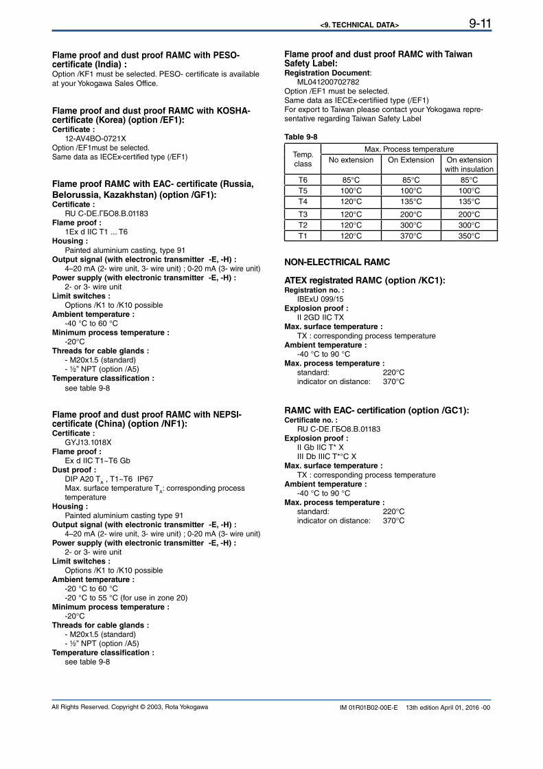
<9. TECHNICAL DATA> 9-11
All Rights Reserved. Copyright © 2003, Rota Yokogawa IM 01R01B02-00E-E 13th edition April 01, 2016 -00
Flame proof and dust proof RAMC with PESO- certificate (India) :Option /KF1 must be selected. PESO- certificate is available at your Yokogawa Sales Office.
Flame proof and dust proof RAMC with KOSHA- certificate (Korea) (option /EF1):Certificate : 12-AV4BO-0721XOption /EF1must be selected.Same data as IECEx-certified type (/EF1)
Flame proof RAMC with EAC- certificate (Russia,
Belorussia, Kazakhstan) (option /GF1):Certificate : RU С-DЕ.ГБО8.В.01183Flame proof : 1Ex d IIC T1 ... T6 Housing :
Painted aluminium casting, type 91Output signal (with electronic transmitter -E, -H) : 4–20 mA (2- wire unit, 3- wire unit) ; 0-20 mA (3- wire unit)Power supply (with electronic transmitter -E, -H) : 2- or 3- wire unitLimit switches : Options /K1 to /K10 possibleAmbient temperature : -40 °C to 60 °C Minimum process temperature : -20°CThreads for cable glands : - M20x1.5 (standard) - ½” NPT (option /A5)Temperature classification :
see table 9-8
Flame proof and dust proof RAMC with NEPSI- certificate (China) (option /NF1):Certificate : GYJ13.1018XFlame proof : Ex d IIC T1~T6 GbDust proof : DIP A20 T
A , T1~T6 IP67
Max. surface temperature TA: corresponding process
temperature Housing : Painted aluminium casting type 91Output signal (with electronic transmitter -E, -H) : 4–20 mA (2- wire unit, 3- wire unit) ; 0-20 mA (3- wire unit)Power supply (with electronic transmitter -E, -H) : 2- or 3- wire unitLimit switches : Options /K1 to /K10 possibleAmbient temperature : -20 °C to 60 °C -20 °C to 55 °C (for use in zone 20)Minimum process temperature : -20°CThreads for cable glands : - M20x1.5 (standard) - ½” NPT (option /A5)Temperature classification : see table 9-8
Flame proof and dust proof RAMC with Taiwan Safety Label: Registration Document: ML041200702782Option /EF1 must be selected.Same data as IECEx-certifiied type (/EF1)For export to Taiwan please contact your Yokogawa repre-sentative regarding Taiwan Safety Label
Table 9-8
Temp. class
Max. Process temperatureNo extension On Extension On extension
with insulation
T6 85°C 85°C 85°CT5 100°C 100°C 100°CT4 120°C 135°C 135°C
T3 120°C 200°C 200°CT2 120°C 300°C 300°CT1 120°C 370°C 350°C
NON-ELECTRICAL RAMC
ATEX registrated RAMC (option /KC1):Registration no. : IBExU 099/15Explosion proof : II 2GD IIC TXMax. surface temperature :
TX : corresponding process temperature Ambient temperature : -40 °C to 90 °C Max. process temperature : standard: 220°C indicator on distance: 370°C
RAMC with EAC- certification (option /GC1):Certificate no. : RU С-DЕ.ГБО8.В.01183Explosion proof : II Gb IIC T* X III Db IIIC T*°C XMax. surface temperature :
TX : corresponding process temperature Ambient temperature : -40 °C to 90 °CMax. process temperature : standard: 220°C indicator on distance: 370°C
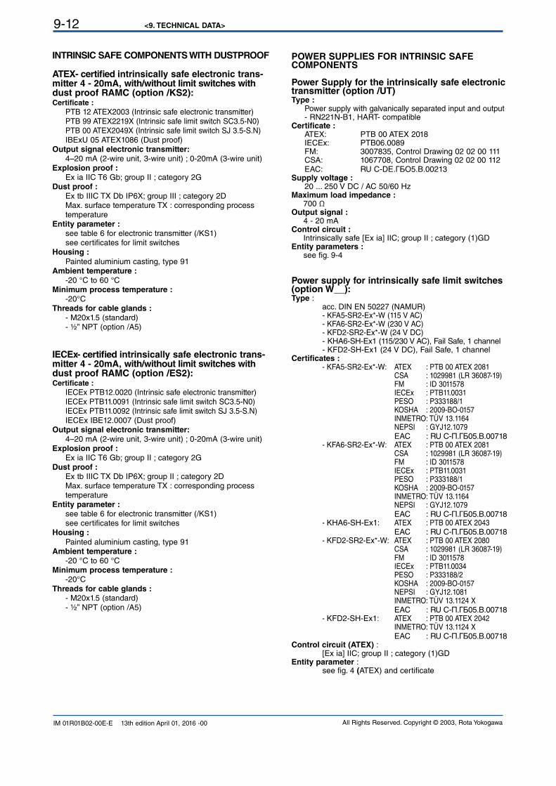
<9. TECHNICAL DATA>9-12
All Rights Reserved. Copyright © 2003, Rota YokogawaIM 01R01B02-00E-E 13th edition April 01, 2016 -00
POWER SUPPLIES FOR INTRINSIC SAFE COMPONENTS
Power Supply for the intrinsically safe electronic transmitter (option /UT)Type : Power supply with galvanically separated input and output - RN221N-B1, HART- compatibleCertificate : ATEX: PTB 00 ATEX 2018 IECEx: PTB06.0089 FM: 3007835, Control Drawing 02 02 00 111 CSA: 1067708, Control Drawing 02 02 00 112 EAC: RU С-DЕ.ГБО5.В.00213Supply voltage : 20 ... 250 V DC / AC 50/60 HzMaximum load impedance : 700 ΩOutput signal : 4 - 20 mAControl circuit : Intrinsically safe [Ex ia] IIC; group II ; category (1)GDEntity parameters : see fig. 9-4
Power supply for intrinsically safe limit switches (option W__):Type : acc. DIN EN 50227 (NAMUR) - KFA5-SR2-Ex*-W (115 V AC) - KFA6-SR2-Ex*-W (230 V AC) - KFD2-SR2-Ex*-W (24 V DC) - KHA6-SH-Ex1 (115/230 V AC), Fail Safe, 1 channel - KFD2-SH-Ex1 (24 V DC), Fail Safe, 1 channel Certificates : - KFA5-SR2-Ex*-W: ATEX : PTB 00 ATEX 2081 CSA : 1029981 (LR 36087-19) FM : ID 3011578 IECEx : PTB11.0031 PESO : P333188/1 KOSHA : 2009-BO-0157 INMETRO: TÜV 13.1164 NEPSI : GYJ12.1079 EAC : RU С-П.ГБ05.В.00718 - KFA6-SR2-Ex*-W: ATEX : PTB 00 ATEX 2081 CSA : 1029981 (LR 36087-19) FM : ID 3011578 IECEx : PTB11.0031 PESO : P333188/1 KOSHA : 2009-BO-0157 INMETRO: TÜV 13.1164 NEPSI : GYJ12.1079 EAC : RU С-П.ГБ05.В.00718 - KHA6-SH-Ex1: ATEX : PTB 00 ATEX 2043 EAC : RU С-П.ГБ05.В.00718 - KFD2-SR2-Ex*-W: ATEX : PTB 00 ATEX 2080 CSA : 1029981 (LR 36087-19) FM : ID 3011578 IECEx : PTB11.0034 PESO : P333188/2 KOSHA : 2009-BO-0157 NEPSI : GYJ12.1081 INMETRO: TÜV 13.1124 X EAC : RU С-П.ГБ05.В.00718 - KFD2-SH-Ex1: ATEX : PTB 00 ATEX 2042 INMETRO: TÜV 13.1124 X EAC : RU С-П.ГБ05.В.00718Control circuit (ATEX) : [Ex ia] IIC; group II ; category (1)GD Entity parameter : see fig. 4 (ATEX) and certificate
INTRINSIC SAFE COMPONENTS WITH DUSTPROOF
ATEX- certified intrinsically safe electronic trans-mitter 4 - 20mA, with/without limit switches with dust proof RAMC (option /KS2):Certificate : PTB 12 ATEX2003 (Intrinsic safe electronic transmitter) PTB 99 ATEX2219X (Intrinsic safe limit switch SC3.5-N0) PTB 00 ATEX2049X (Intrinsic safe limit switch SJ 3.5-S.N) IBExU 05 ATEX1086 (Dust proof)Output signal electronic transmitter: 4–20 mA (2-wire unit, 3-wire unit) ; 0-20mA (3-wire unit)Explosion proof : Ex ia IIC T6 Gb; group II ; category 2GDust proof : Ex tb IIIC TX Db IP6X; group III ; category 2D Max. surface temperature TX : corresponding process temperature Entity parameter : see table 6 for electronic transmitter (/KS1) see certificates for limit switches Housing :
Painted aluminium casting, type 91Ambient temperature : -20 °C to 60 °C Minimum process temperature : -20°CThreads for cable glands : - M20x1.5 (standard) - ½” NPT (option /A5)
IECEx- certified intrinsically safe electronic trans-mitter 4 - 20mA, with/without limit switches with dust proof RAMC (option /ES2):Certificate : IECEx PTB12.0020 (Intrinsic safe electronic transmitter) IECEx PTB11.0091 (Intrinsic safe limit switch SC3.5-N0) IECEx PTB11.0092 (Intrinsic safe limit switch SJ 3.5-S.N) IECEx IBE12.0007 (Dust proof)Output signal electronic transmitter: 4–20 mA (2-wire unit, 3-wire unit) ; 0-20mA (3-wire unit)Explosion proof : Ex ia IIC T6 Gb; group II ; category 2GDust proof : Ex tb IIIC TX Db IP6X; group II ; category 2D Max. surface temperature TX : corresponding process temperature Entity parameter : see table 6 for electronic transmitter (/KS1) see certificates for limit switches Housing :
Painted aluminium casting, type 91Ambient temperature : -20 °C to 60 °C Minimum process temperature : -20°C Threads for cable glands : - M20x1.5 (standard) - ½” NPT (option /A5)
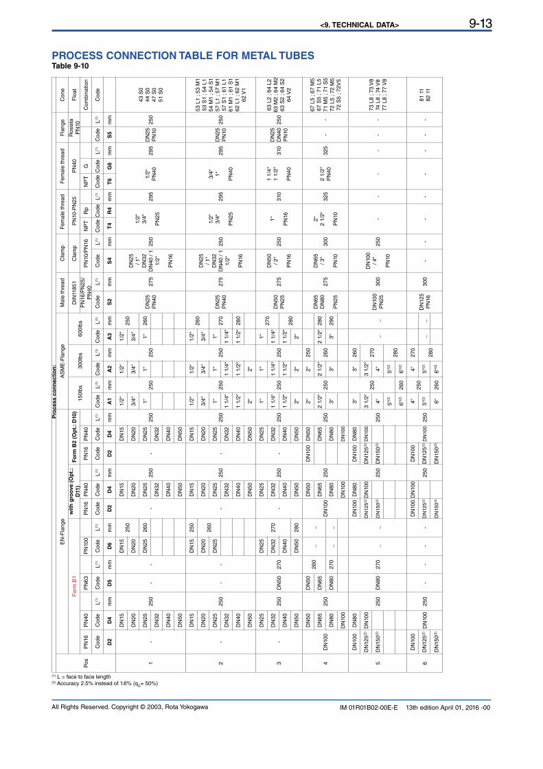
<9. TECHNICAL DATA> 9-13
All Rights Reserved. Copyright © 2003, Rota Yokogawa IM 01R01B02-00E-E 13th edition April 01, 2016 -00
PROCESS CONNECTION TABLE FOR METAL TUBESTable 9-10
Pro
cess c
on
necti
on
:
Pos
EN
-Fla
nge
AS
ME
-Fla
nge
Male
thre
ad
Cla
mp
Fem
ale
thre
ad
Fem
ale
thre
adF
lang
eC
one
For
m B
1w
ith
gro
ove (
Op
t.:
D11
)F
orm
B2 (
Op
t.:
D10)
150l
bs300lb
s600lb
sD
IN11
851
Cla
mp
PN
10-P
N25
PN
40R
osis
ta
PN
10F
loat
PN
16P
N40
PN
63P
N10
0P
N16
PN
40P
N16
PN
40P
N16
/PN
25/
PN
40P
N10
/PN
16N
PT
Rp
NP
TG
Com
bin
ation
Code
Code
L(1)
Code
L(1)
Code
L(1)
Code
Code
L(1)
Code
Code
L(1)
Code
L(1)
Code
L(1)
Code
L(1)
Code
L(1)
Code
L(1)
Code
Code
L(1)
Code
Code
L(1)
Code
L(1)
Code
D2
D4
mm
D5
mm
D6
mm
D2
D4
mm
D2
D4
mm
A1
mm
A2
mm
A3
mm
S2
mm
S4
mm
T4
R4
mm
T6
G6
mm
S5
mm
1-
DN
15
250
--
DN
1525
0
-
DN
15
250
-
DN
15
250
1/2
“
250
1/2
“
250
1/2
“25
0
DN
25
PN
4027
5
DN
25
/ 1“
DN
32
DN
40 /
1 1/2
“
PN
16
250
1/2
“
3/4
“
PN
25
295
1/2
“
PN
4029
5D
N25
PN
1025
0
43 S
0 44
S0
47 S
0 51
S0
DN
20D
N20
DN
20D
N20
3/4
“3/4
“3/4
“
DN
25D
N25
260
DN
25D
N25
1“
1“
1“
260
DN
32D
N32
DN
32
DN
40D
N40
DN
40
DN
50D
N50
DN
50
2-
DN
15
250
--
DN
1525
0
-
DN
15
250
-
DN
15
250
1/2
“
250
1/2
“
250
1/2
“260
DN
25
PN
4027
5
DN
25
/ 1“
DN
32
DN
40 /
1 1/2
“
PN
16
250
1/2
“
3/4
“
PN
25
295
3/4
“
1“
PN
40
295
DN
25
PN
1025
0
53 L
1 ; 5
3 M
1 53
S1
; 54
L1
54 M
1 ; 5
4 S
1 57
L1
; 57
M1
57 S
1 ; 6
1 L1
61 M
1 ; 6
1 S
1 62
L1
; 62
M1
62 V
1
DN
20D
N20
260
DN
20D
N20
3/4
“3/4
“3/4
“
DN
25D
N25
DN
25D
N25
1“
1“
1“
270
DN
32D
N32
DN
321 1
/4“
1 1
/4“
1 1
/4“
DN
40D
N40
DN
401 1
/2“
1 1
/2“
1 1
/2“
280
DN
50D
N50
DN
502“
2“
3-
DN
25
250
DN
50270
DN
25
270
-
DN
25
250
-
DN
25
250
1“
250
1“
250
1“
270
DN
50
PN
2527
5
DN
50
/ 2“
PN
16
250
1“
PN
16310
1 1
/4“
1 1
/2“
PN
40
310
DN
25
DN
40
PN
1025
0
63 L
2 ; 6
4 L2
63 M
2 ; 6
4 M
2 63
S2
; 64
S2
64 V
2
DN
32D
N32
DN
32D
N32
1 1
/4“
1 1
/4“
1 1
/4“
DN
40D
N40
DN
40D
N40
1 1
/2“
1 1
/2“
1 1
/2“
280
DN
50D
N50
280
DN
50D
N50
2“
2“
2“
4D
N10
0
DN
50
250
DN
50260
__
DN
100
DN
50
250
DN
100
DN
50
250
2“
250
2“
250
DN
65
DN
80
PN
25
275
DN
65
/ 3“
PN
10
300
2“
2 1
/2“
PN
10
325
2 1
/2“
PN
4032
5-
-
67 L
5 ; 6
7 M
5 67
S5
; 71
L5
71 M
5 ; 7
1 S
5 72
L5
; 72
M5
72 S
5 ; 7
2V5
DN
65D
N65
DN
65D
N65
2 1
/2“
2 1
/2“
260
2 1
/2“
280
DN
80D
N80
270
__
DN
80D
N80
3“
3“
3“
290
DN
100
DN
100
DN
100
5
DN
100
DN
80
250
DN
80270
__
DN
100
DN
80
250
DN
100
DN
80
250
3“
250
3“
260
__
DN
100
PN
25300
DN
100
/ 4“
PN
10
250
--
--
--
73 L
8 ; 7
3 V
8 74
L8
; 74
V8
77 L
8 ; 7
7 V
8
DN
125(2
)D
N10
0D
N12
5(2)D
N10
0D
N12
5(2)D
N10
03 1
/2“
3 1
/2“
270
DN
150(2
)D
N15
0(2)
DN
150(2
)4“
4“
5“(2
)5“
(2)
280
6“(2
)260
6“(2
)
6
DN
100
DN
100
250
--
--
DN
100
DN
100
250
DN
100
DN
100
250
4“
250
4“
270
DN
125
PN
16300
--
--
--
--
81 1
1
82 1
1D
N12
5(2)
DN
125(2
)D
N12
5(2)
5“(2
)5“
(2)
280
__
DN
150(2
)D
N15
0(2)
DN
150(2
)6“
260
6“(2
)
(1) L = face to face length(2) Accuracy 2.5% instead of 1.6% (q
G= 50%)
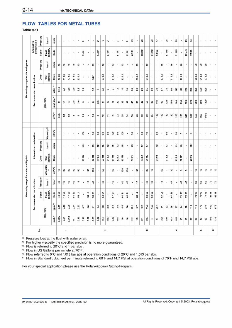
<9. TECHNICAL DATA>9-14
All Rights Reserved. Copyright © 2003, Rota YokogawaIM 01R01B02-00E-E 13th edition April 01, 2016 -00
FLOW TABLES FOR METAL TUBES
Table 9-11
Pos
.
Measu
rin
g r
an
ge f
or
wate
r an
d liq
uid
sM
easu
rin
g r
an
ge f
or
air
an
d g
ases
Reco
mm
en
ded
co
mb
inati
on
Alt
ern
ati
ve c
om
bin
ati
on
Reco
mm
en
ded
co
mb
inati
on
Alt
ern
ati
ve
co
mb
inati
on
Max. fl
ow
Co
ne-
Pre
ssu
reC
on
e-
Pre
ssu
re
Max. fl
ow
Co
ne-
Pre
ssu
reC
on
e-
Pre
ssu
re
Flo
at-
co
mb
in.
loss a
)V
isco
sit
y
b)
Flo
at-
co
mb
in.
loss a
)V
isco
sit
y b
)F
loat-
co
mb
in.
loss a
)F
loat-
co
mb
in.
loss a
)
m3/h
c)
gp
m d
)C
od
em
bar
mP
a*s
Co
de
mb
ar
mP
a*s
m3/h
c)
m3/h
i.
N. e
)scfm
f)
Co
de
mb
ar
Co
de
mb
ar
1
0.0
25
0.1
143 S
040
10
--
-0.7
50
0.4
443 S
045
--
0.0
40.1
844 S
040
80
--
-1.
21.
10.7
44 S
045
--
0.0
63
0.2
847 S
040
80
--
-1.
81.
71.
05
47 S
045
--
0.1
0.4
451 S
040
80
--
-3
2.8
1.75
51 S
045
--
2
0.1
30.5
753 L
112
50
--
-4
3.6
2.3
53 L
113
--
0.1
60.7
--
-53 M
115
10
05.5
53.2
--
53 M
121
0.2
21.
054 L
112
50
--
--
--
--
-
0.2
51.
153 S
140
10
054 M
115
50
6.5
63.8
54L
113
--
0.3
21.
4-
--
57 L
112
50
98.5
5-
-54 M
121
0.4
1.8
54 S
140
50
57 M
115
50
10
95.7
57 L
113
-v
0.5
2.2
--
-61 L
112
50
14
13
8-
-57 M
121
0.6
32.8
57 S
140
50
61 M
115
10
016
15
961 L
113
--
0.8
3.5
--
-62 L
112
50
22
20
12
--
61 M
121
1.0
4.4
61 S
140
10
062 M
115
10
025
23
14
62 L
113
--
1.6
7.0
62 S
140
10
0-
--
34
32
20
--
62 M
121
2.2
10.1
--
-62 V
145
50
50
45
28
--
62 S
145
3
1.3
5.7
63 L
217
50
--
-40
36
23
63 L
219
--
2.1
9.2
--
-64 L
217
50
50
47
29
--
63 M
223
2.5
11.0
63 S
242
30
64 M
217
10
60
55
35
64 L
219
--
417.
664 S
242
10
--
-85
80
50
--
64 M
223
626.4
--
-64 V
243
50
12
011
070
--
64 S
247
4
3.2
14
67 L
513
50
--
-10
090
57
67 L
516
--
5.0
22
--
-71 L
513
50
13
012
075
--
67 M
525
6.3
28
67 S
547
30
--
-16
015
090
71 L
516
--
8.5
37
--
-72 L
513
50
20
018
011
5-
-71 M
525
10
44
71 S
547
572 M
519
5250
230
14
072 L
516
--
16
70
72 S
547
5-
--
340
320
20
0-
-72 m
525
25
110
--
-72 V
563
550
0470
290
--
72 S
554
5
25
110
73 V
860
10
--
-550
50
0320
73 L
830
--
40
176
74 V
860
10
--
-850
80
050
074 L
830
--
63
277
77 V
860
10
--
-14
00
13
00
80
077 L
830
--
610
0440
81 1
170
10
--
--
--
--
--
13
0572
82 1
170
10
--
--
--
--
--
a) Pressure loss at the float with water or air. b) For higher viscosity the specified precision is no more guaranteed. c) Flow is referred to 20°C and 1 bar abs .d) Flow in US Gallons per minute at 70°F .e) Flow referred to 0°C and 1.013 bar abs at operation conditions of 20°C and 1,013 bar abs.f) Flow in Standard cubic feet per minute referred to 60°F and 14,7 PSI at operation conditions of 70°F und 14,7 PSI abs.
For your special application please use the Rota Yokogawa Sizing-Program.
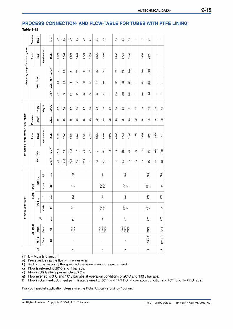
<9. TECHNICAL DATA> 9-15
All Rights Reserved. Copyright © 2003, Rota Yokogawa IM 01R01B02-00E-E 13th edition April 01, 2016 -00
PROCESS CONNECTION- AND FLOW-TABLE FOR TUBES WITH PTFE LINING
Table 9-12
Po
s.
Pro
cess c
on
necti
on
M
easu
rin
g r
an
ge f
or
wate
r an
d l
iqu
ids
Measu
rin
g r
an
ge f
or
air
an
d g
ases
EN
-Fla
ng
eA
SM
E-F
lan
ge
Max. F
low
Co
ne-
Pre
ssu
re
Max. F
low
Co
ne-
Pre
ssu
re
PN
16
PN
40
L(1
)150 lb
s30
0 lb
sF
loat-
loss a
)V
isco
Flo
at-
loss a
)
Co
de
Co
de
Co
de
L(1
)C
od
eL
(1)
co
mb
inati
on
sit
y
b)
co
mb
inati
on
D2
D4
mm
A1
mm
A2
mm
m3/h
c)
gp
m
d)
Co
de
mb
ar
mP
a*s
m3/h
c)
m3/h
i.
N.
e)
scfm
f)
Co
de
mb
ar
2-
DN
15
DN
25
250
¾“
1“
250
¾“
1“
250
0.1
0.45
51 A
116
503.
53.3
251
A1
20
0.1
60.7
52 A
116
505
4.7
2.9
52 A
120
0.25
1.12
53 A
116
508.
58
553
A1
20
0.4
1.8
54 A
116
5013
12
7.5
54 A
120
0.6
32.8
57 A
116
5020
18
1157
A1
20
14.
561
V1
18
5034
32
20
61 V
122
3-
DN
25D
N40
D
N50
25
01¼
“
1½
“25
01¼
“
1½
“25
0
1.6
762 A
220
30
5047
29
62 A
225
2.5
11.2
63 A
220
10
8580
5063 A
225
418
63 V
222
50-
--
--
4-
DN
50
DN
65
D
N80
25
02½
“
3“
260
2½
“
3“
270
418
64 A
520
30
13
012
075
64 A
525
6.3
28
67 A
520
30
200
18
011
567
A5
25
10
4571
A5
20
535
0330
200
71 A
525
16
70
71 V
522
10
--
--
-
5 D
N10
0D
N80
250
3½
“
4“
270
3½
“
4“
270
16
70
72 V
825
10
500
470
290
72 V
827
2511
073
V8
2510
850
800
500
73 V
827
40
18
074
V8
2510
--
--
-
6D
N10
0D
N10
025
04“
270
4“
270
63
280
77 1
030
10
--
--
-
(1) L = Mounting length a) Pressure loss at the float with water or air. b) As from this viscosity the specified precision is no more guaranteed.
c) Flow is referred to 20°C and 1 bar abs. d) Flow in US Gallons per minute at 70°F. e) Flow referred to 0°C and 1.013 bar abs at operation conditions of 20°C and 1,013 bar abs. f) Flow in Standard cubic feet per minute referred to 60°F and 14,7 PSI at operation conditions of 70°F und 14,7 PSI abs.
For your special application please use the Rota Yokogawa Sizing-Program.
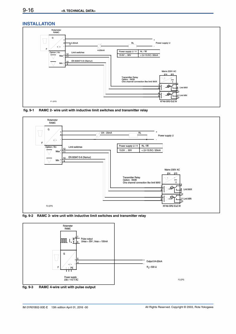
<9. TECHNICAL DATA>9-16
All Rights Reserved. Copyright © 2003, Rota YokogawaIM 01R01B02-00E-E 13th edition April 01, 2016 -00
fig. 9-3 RAMC 4-wire unit with pulse output
F
G
RAMC
230 / 115 V AC
4
Power supply
Output 0/4-20mA
R < 500 ΩL
Rotameter
PE--
5
7
6
Pulse outputUmax = 30V ; Imax = 100mA
-
+
-
+
+
-
F3.EPS
fig. 9-2 RAMC 3- wire unit with inductive limit switches and transmitter relay
15
4
6
3
1
14
12
1011
87
9U
F
G
RAMC
A Power supply U
Mains 230V AC
KFA6-SR2-Ex2.W
Option: /W2BTransmitter Relay
Limit MIN
Limit MAX
Option / Kn
Rotameter
Max
Min
12
11
109
Limit switches
EN 60947-5-6 (Namur)
One channel connection like limit MAX
0/4 - 20mA RL
-
+
-
+
-
+
-
+
~ ~
+-
+-
Power supply U / V RL / W
13.5V ... 30V < (U-13.5V) / 20mA
F2.EPS
fig. 9-1 RAMC 2- wire unit with inductive limit switches and transmitter relay
15
4
6
3
1
14
12
1011
87
9U
F
G
RAMC
A Power supply U
Mains 230V AC
KFA6-SR2-Ex2.W
Option: /W2BTransmitter Relay
Limit MIN
Limit MAX
Option / Kn
Rotameter
4-20mA
Max
Min
12
11
109
Limit switches
EN 60947-5-6 (Namur)
One channel connection like limit MAX
4-20mA
RL
-
+
-
+
-
+
-
+
~ ~
+-
+-
Power supply U / V RL / W
13.5V ... 30V < (U-13.5V) / 20mA
F1.EPS
INSTALLATION
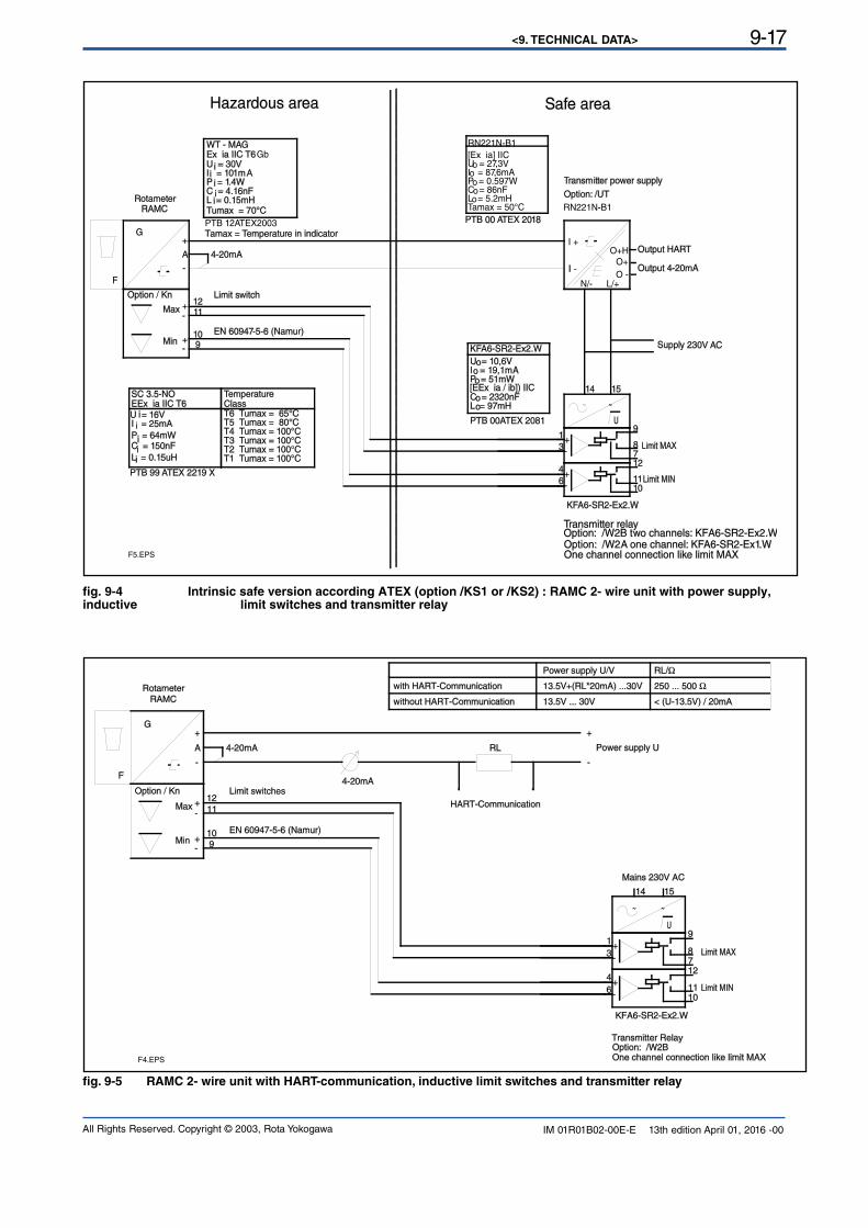
<9. TECHNICAL DATA> 9-17
All Rights Reserved. Copyright © 2003, Rota Yokogawa IM 01R01B02-00E-E 13th edition April 01, 2016 -00
fig. 9-5 RAMC 2- wire unit with HART-communication, inductive limit switches and transmitter relay
15
4
6
3
1
14
12
1011
87
9U
F
G
RAMC
A Power supply U
Mains 230V AC
KFA6-SR2-Ex2.W
Option: /W2BTransmitter Relay
Limit MIN
Limit MAX
Option / Kn
Rotameter
4-20mA
Max
Min
12
11
109
Limit switches
EN 60947-5-6 (Namur)
One channel connection like limit MAX
4-20mA
RL
HART-Communication
with HART-Communication
without HART-Communication
Power supply U/V RL/Ω
13.5V+(RL*20mA) ...30V
13.5V ... 30V < (U-13.5V) / 20mA
250 ... 500 Ω
-
+
-
+
-
+
-
+
~ ~
+-
+-
F4.EPS
fig. 9-4 Intrinsic safe version according ATEX (option /KS1 or /KS2) : RAMC 2- wire unit with power supply, inductive limit switches and transmitter relay
15
4
6
3
1
14
12
1011
87
9
1211
109
I -
I +
L/+N/-O -
O+Output 4-20mA
O+H Output HART
U
F
G
RAMC
A
Supply 230V AC
KFA6-SR2-Ex2.W
Option: /W2B two channels: KFA6-SR2-Ex2.WTransmitter relay
Limit MIN
Limit MAX
Option / Kn
Rotameter
4-20mA
Max
Min
Limit switch
EN 60947-5-6 (Namur)
One channel connection like limit MAX
I = 101mAP = 1.4WC = 4.16nF
U = 30V
L = 0.15mH
WT - MAGEx ia IIC T6Gb
PTB 12ATEX2003
Tumax = 70°C
Tamax = Temperature in indicator
C = 150nF
EEx ia IIC T6
L = 0.15uH
SC 3.5-NO
P = 64mW
I = 25mAU = 16V
Temperature
T4 Tumax = 100°CT3 Tumax = 100°CT2 Tumax = 100°CT1 Tumax = 100°C
Class
T5 Tumax = 80°CT6 Tumax = 65°C
PTB 99 ATEX 2219 X
PTB 00 ATEX 2018
Transmitter power supply
Option: /UT
Option: /W2A one channel: KF A6-SR2-Ex1.W
C = 2320nF
I = 19,1mAP = 51mW
U = 10,6V
L = 97mH
PTB 00ATEX 2081
[EEx ia / ib]) IIC
KFA6-SR2-Ex2.W
RN221N-B1
RN221N-B1
Tamax = 50°C
C = 86nFL = 5.2mH
U = 27,3V
P = 0.597W
[Ex ia] IIC
I = 87,6mAo
oo
oo
-
+
-
+
-
+
~ ~
+-
+-
i
ii
i
iii
i
i
o
o
o
oo
F5.EPS
i
Hazardous area Safe area
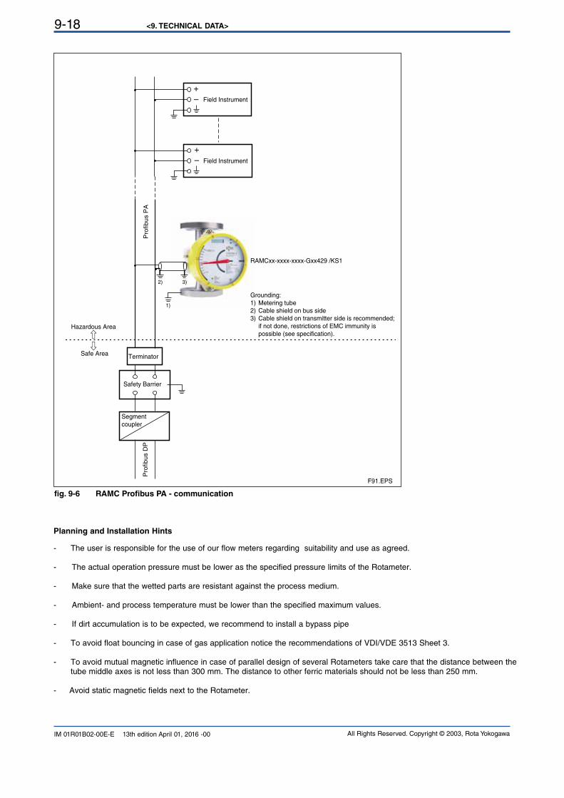
<9. TECHNICAL DATA>9-18
All Rights Reserved. Copyright © 2003, Rota YokogawaIM 01R01B02-00E-E 13th edition April 01, 2016 -00
Planning and Installation Hints
- The user is responsible for the use of our flow meters regarding suitability and use as agreed.
- The actual operation pressure must be lower as the specified pressure limits of the Rotameter.
- Make sure that the wetted parts are resistant against the process medium.
- Ambient- and process temperature must be lower than the specified maximum values.
- If dirt accumulation is to be expected, we recommend to install a bypass pipe
- To avoid float bouncing in case of gas application notice the recommendations of VDI/VDE 3513 Sheet 3.
- To avoid mutual magnetic influence in case of parallel design of several Rotameters take care that the distance between the tube middle axes is not less than 300 mm. The distance to other ferric materials should not be less than 250 mm.
- Avoid static magnetic fields next to the Rotameter.
+
–
+
–
Field Instrument
Field Instrument
Safe Area
Hazardous Area
Terminator
Safety Barrier
F91.EPS
RAMCxx-xxxx-xxxx-Gxx429 /KS1
Pro
fib
us P
AP
rofib
us D
P
Segment
coupler
Grounding:
1) Metering tube
2) Cable shield on bus side
3) Cable shield on transmitter side is recommended;
if not done, restrictions of EMC immunity is
possible (see specification).
3)2)
1)
fig. 9-6 RAMC Profibus PA - communication
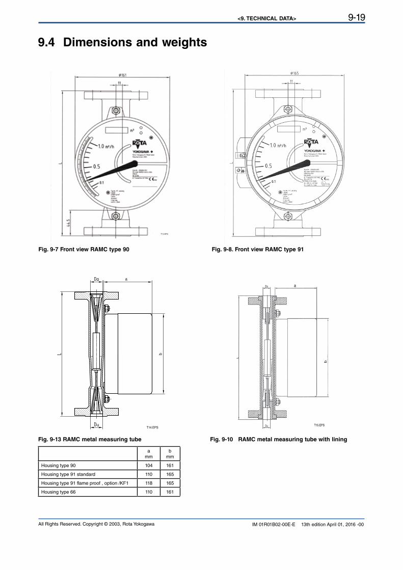
<9. TECHNICAL DATA> 9-19
All Rights Reserved. Copyright © 2003, Rota Yokogawa IM 01R01B02-00E-E 13th edition April 01, 2016 -00
9.4 Dimensions and weights
Fig. 9-7 Front view RAMC type 90
T12.EPS
Fig. 9-8. Front view RAMC type 91
Fig. 9-13 RAMC metal measuring tube Fig. 9-10 RAMC metal measuring tube with lining
T14.EPS
a
b
T15.EPS
a
b
a
mm
b
mm
Housing type 90 104 161
Housing type 91 standard 110 165
Housing type 91 flame proof , option /KF1 118 165
Housing type 66 110 161
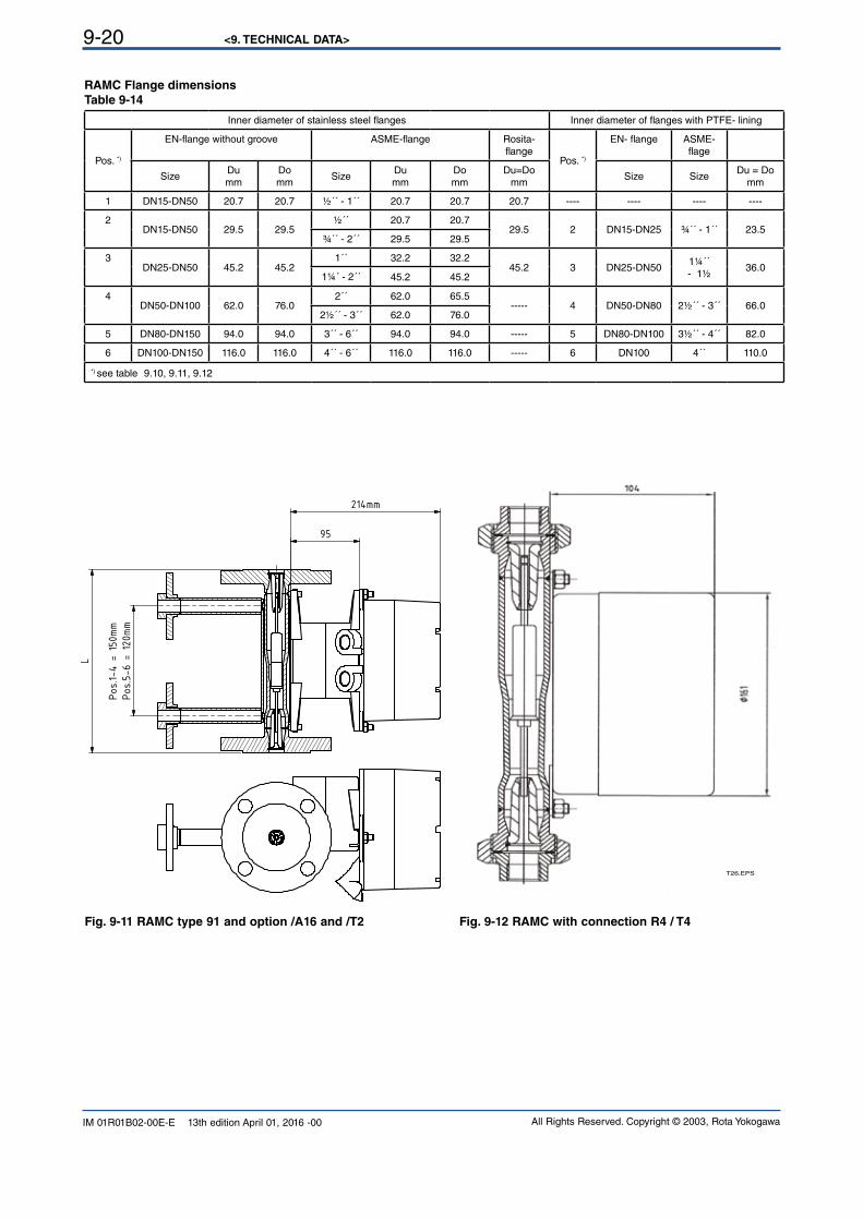
<9. TECHNICAL DATA>9-20
All Rights Reserved. Copyright © 2003, Rota YokogawaIM 01R01B02-00E-E 13th edition April 01, 2016 -00
RAMC Flange dimensions
Table 9-14
Inner diameter of stainless steel flanges Inner diameter of flanges with PTFE- lining
Pos. *)
EN-flange without groove ASME-flange Rosita-
flangePos. *)
EN- flange ASME-flage
SizeDu
mm
Do
mmSize
Du
mm
Do
mm
Du=Do
mmSize Size
Du = Do
mm
1 DN15-DN50 20.7 20.7 ½´´ - 1´´ 20.7 20.7 20.7 ---- ---- ---- ----
2DN15-DN50 29.5 29.5
½´´ 20.7 20.729.5 2 DN15-DN25 ¾´´ - 1´´ 23.5
¾´´ - 2´´ 29.5 29.5
3DN25-DN50 45.2 45.2
1´´ 32.2 32.245.2 3 DN25-DN50
1¼´´ - 1½
36.01¼´ - 2´´ 45.2 45.2
4DN50-DN100 62.0 76.0
2´´ 62.0 65.5----- 4 DN50-DN80 2½´´ - 3´´ 66.0
2½´´ - 3´´ 62.0 76.0
5 DN80-DN150 94.0 94.0 3´´ - 6´´ 94.0 94.0 ----- 5 DN80-DN100 3½´´ - 4´´ 82.0
6 DN100-DN150 116.0 116.0 4´´ - 6´´ 116.0 116.0 ----- 6 DN100 4´´ 110.0
*) see table 9.10, 9.11, 9.12
Fig. 9-11 RAMC type 91 and option /A16 and /T2 Fig. 9-12 RAMC with connection R4 / T4
T26.EPS
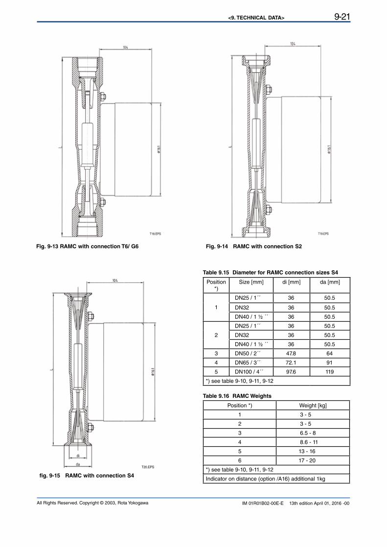
<9. TECHNICAL DATA> 9-21
All Rights Reserved. Copyright © 2003, Rota Yokogawa IM 01R01B02-00E-E 13th edition April 01, 2016 -00
Fig. 9-13 RAMC with connection T6/ G6 Fig. 9-14 RAMC with connection S2
T18.EPS T19.EPS
fig. 9-15 RAMC with connection S4
T20.EPS
Table 9.15 Diameter for RAMC connection sizes S4
Position *)
Size [mm] di [mm] da [mm]
1
DN25 / 1´´ 36 50.5
DN32 36 50.5
DN40 / 1 ½ ´´ 36 50.5
2
DN25 / 1´´ 36 50.5
DN32 36 50.5
DN40 / 1 ½ ´´ 36 50.5
3 DN50 / 2´´ 47.8 64
4 DN65 / 3´´ 72.1 91
5 DN100 / 4´´ 97.6 119
*) see table 9-10, 9-11, 9-12
Table 9.16 RAMC Weights
Position *) Weight [kg]
1 3 - 5
2 3 - 5
3 6.5 - 8
4 8.6 - 11
5 13 - 16
6 17 - 20
*) see table 9-10, 9-11, 9-12
Indicator on distance (option /A16) additional 1kg
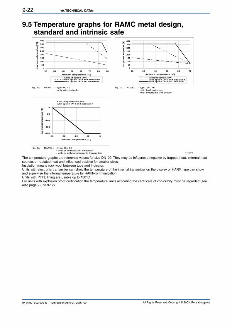
<9. TECHNICAL DATA>9-22
All Rights Reserved. Copyright © 2003, Rota YokogawaIM 01R01B02-00E-E 13th edition April 01, 2016 -00
9.5 Temperature graphs for RAMC metal design, standard and intrinsic safe
T10.EPS
0
50
100
150
200
250
300
350
400
20 30 40 50 60 70 80 90
Ambient temperature [°C]
max
pro
cess
tem
pera
ture
[°C
]
without option /A16with option /A16 and insulationwith option /A16, no insulation
0
50
100
150
200
250
300
350
400
20 30 40 50 60 70
Ambient temperature [°C]
max
pro
cess
tem
pera
ture
[°C
]
without option /A16with option /A16 and insulationwith option /A16, no insulation
-196
-150
-100
-50
0
-30 -20 -10 0
Ambient temperature [°C]
min
pro
cess
tem
pera
ture
[°C
]
Low temperature curve
with option /A16 and insulation
fig. 7a RAMC : - type 90 / 91
- only with indicator
fig. 7b RAMC : - type 90 / 91
- with limit switches
- with electronic transmitter
fig. 7c RAMC : - type 90 / 91
- with or without limit switches
- with or without electronic transmitter
-40
The temperature graphs are reference values for size DN100. They may be influenced negative by trapped heat, external heat sources or radiated heat and influenced positive for smaller sizes.Insulation means rock wool between tube and indicator.Units with electronic transmitter can show the temperature of the internal transmitter on the display or HART- type can show and supervise the internal temperature by HART-communication.Units with PTFE lining are usable up to 130°C.For units with explosion proof certification the temperature limits according the certificate of conformity must be regarded (see also page 9-8 to 9-12).
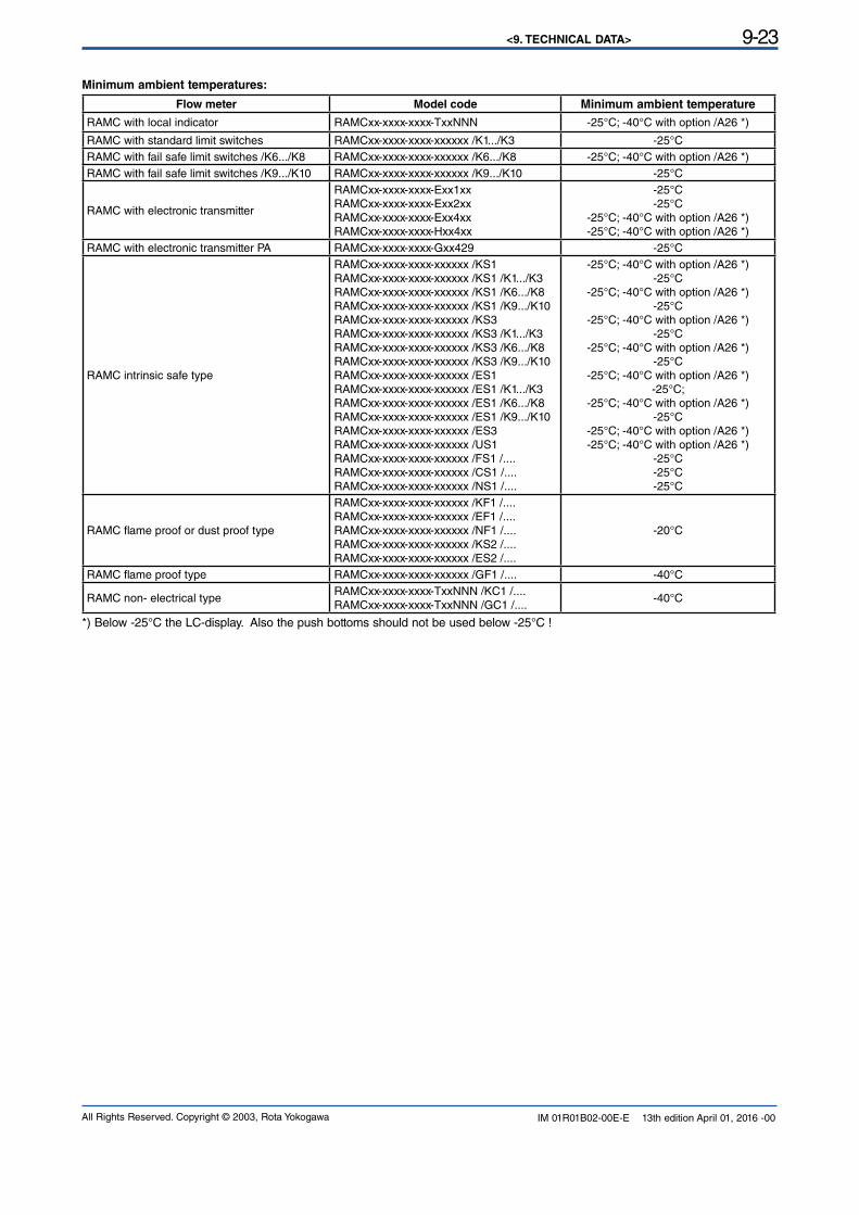
<9. TECHNICAL DATA> 9-23
All Rights Reserved. Copyright © 2003, Rota Yokogawa IM 01R01B02-00E-E 13th edition April 01, 2016 -00
Minimum ambient temperatures:
Flow meter Model code Minimum ambient temperature
RAMC with local indicator RAMCxx-xxxx-xxxx-TxxNNN -25°C; -40°C with option /A26 *)
RAMC with standard limit switches RAMCxx-xxxx-xxxx-xxxxxx /K1.../K3 -25°CRAMC with fail safe limit switches /K6.../K8 RAMCxx-xxxx-xxxx-xxxxxx /K6.../K8 -25°C; -40°C with option /A26 *) RAMC with fail safe limit switches /K9.../K10 RAMCxx-xxxx-xxxx-xxxxxx /K9.../K10 -25°C
RAMC with electronic transmitter
RAMCxx-xxxx-xxxx-Exx1xxRAMCxx-xxxx-xxxx-Exx2xxRAMCxx-xxxx-xxxx-Exx4xxRAMCxx-xxxx-xxxx-Hxx4xx
-25°C-25°C
-25°C; -40°C with option /A26 *) -25°C; -40°C with option /A26 *)
RAMC with electronic transmitter PA RAMCxx-xxxx-xxxx-Gxx429 -25°C
RAMC intrinsic safe type
RAMCxx-xxxx-xxxx-xxxxxx /KS1RAMCxx-xxxx-xxxx-xxxxxx /KS1 /K1.../K3
RAMCxx-xxxx-xxxx-xxxxxx /KS1 /K6.../K8
RAMCxx-xxxx-xxxx-xxxxxx /KS1 /K9.../K10
RAMCxx-xxxx-xxxx-xxxxxx /KS3RAMCxx-xxxx-xxxx-xxxxxx /KS3 /K1.../K3
RAMCxx-xxxx-xxxx-xxxxxx /KS3 /K6.../K8
RAMCxx-xxxx-xxxx-xxxxxx /KS3 /K9.../K10
RAMCxx-xxxx-xxxx-xxxxxx /ES1RAMCxx-xxxx-xxxx-xxxxxx /ES1 /K1.../K3
RAMCxx-xxxx-xxxx-xxxxxx /ES1 /K6.../K8
RAMCxx-xxxx-xxxx-xxxxxx /ES1 /K9.../K10
RAMCxx-xxxx-xxxx-xxxxxx /ES3RAMCxx-xxxx-xxxx-xxxxxx /US1RAMCxx-xxxx-xxxx-xxxxxx /FS1 /....RAMCxx-xxxx-xxxx-xxxxxx /CS1 /....RAMCxx-xxxx-xxxx-xxxxxx /NS1 /....
-25°C; -40°C with option /A26 *)-25°C
-25°C; -40°C with option /A26 *)-25°C
-25°C; -40°C with option /A26 *)-25°C
-25°C; -40°C with option /A26 *)-25°C
-25°C; -40°C with option /A26 *)-25°C;
-25°C; -40°C with option /A26 *)-25°C
-25°C; -40°C with option /A26 *)-25°C; -40°C with option /A26 *)
-25°C-25°C-25°C
RAMC flame proof or dust proof type
RAMCxx-xxxx-xxxx-xxxxxx /KF1 /....RAMCxx-xxxx-xxxx-xxxxxx /EF1 /....RAMCxx-xxxx-xxxx-xxxxxx /NF1 /....RAMCxx-xxxx-xxxx-xxxxxx /KS2 /....RAMCxx-xxxx-xxxx-xxxxxx /ES2 /....
-20°C
RAMC flame proof type RAMCxx-xxxx-xxxx-xxxxxx /GF1 /.... -40°C
RAMC non- electrical typeRAMCxx-xxxx-xxxx-TxxNNN /KC1 /....RAMCxx-xxxx-xxxx-TxxNNN /GC1 /....
-40°C
*) Below -25°C the LC-display. Also the push bottoms should not be used below -25°C !
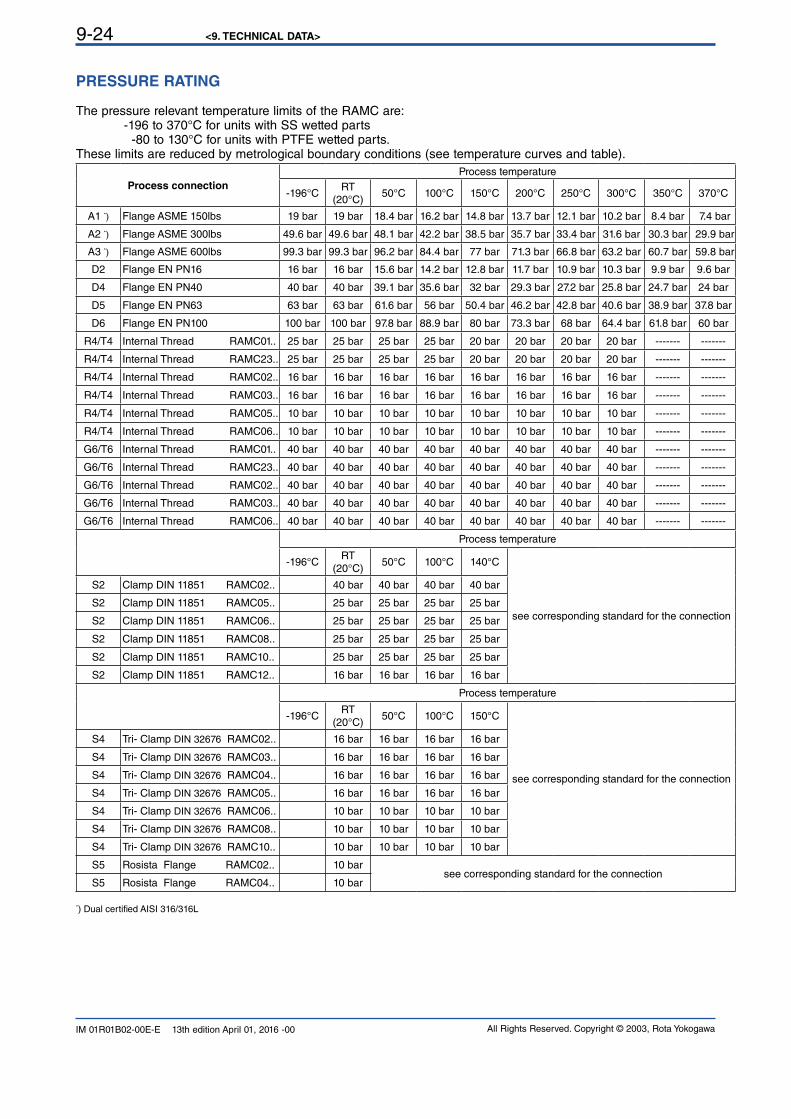
<9. TECHNICAL DATA>9-24
All Rights Reserved. Copyright © 2003, Rota YokogawaIM 01R01B02-00E-E 13th edition April 01, 2016 -00
PRESSURE RATING
The pressure relevant temperature limits of the RAMC are: -196 to 370°C for units with SS wetted parts -80 to 130°C for units with PTFE wetted parts.These limits are reduced by metrological boundary conditions (see temperature curves and table).
Process connection
Process temperature
-196°CRT
(20°C)50°C 100°C 150°C 200°C 250°C 300°C 350°C 370°C
A1 *) Flange ASME 150lbs 19 bar 19 bar 18.4 bar 16.2 bar 14.8 bar 13.7 bar 12.1 bar 10.2 bar 8.4 bar 7.4 bar
A2 *) Flange ASME 300lbs 49.6 bar 49.6 bar 48.1 bar 42.2 bar 38.5 bar 35.7 bar 33.4 bar 31.6 bar 30.3 bar 29.9 bar
A3 *) Flange ASME 600lbs 99.3 bar 99.3 bar 96.2 bar 84.4 bar 77 bar 71.3 bar 66.8 bar 63.2 bar 60.7 bar 59.8 bar
D2 Flange EN PN16 16 bar 16 bar 15.6 bar 14.2 bar 12.8 bar 11.7 bar 10.9 bar 10.3 bar 9.9 bar 9.6 bar
D4 Flange EN PN40 40 bar 40 bar 39.1 bar 35.6 bar 32 bar 29.3 bar 27.2 bar 25.8 bar 24.7 bar 24 bar
D5 Flange EN PN63 63 bar 63 bar 61.6 bar 56 bar 50.4 bar 46.2 bar 42.8 bar 40.6 bar 38.9 bar 37.8 bar
D6 Flange EN PN100 100 bar 100 bar 97.8 bar 88.9 bar 80 bar 73.3 bar 68 bar 64.4 bar 61.8 bar 60 bar
R4/T4 Internal Thread RAMC01.. 25 bar 25 bar 25 bar 25 bar 20 bar 20 bar 20 bar 20 bar ------- -------
R4/T4 Internal Thread RAMC23.. 25 bar 25 bar 25 bar 25 bar 20 bar 20 bar 20 bar 20 bar ------- -------
R4/T4 Internal Thread RAMC02.. 16 bar 16 bar 16 bar 16 bar 16 bar 16 bar 16 bar 16 bar ------- -------
R4/T4 Internal Thread RAMC03.. 16 bar 16 bar 16 bar 16 bar 16 bar 16 bar 16 bar 16 bar ------- -------
R4/T4 Internal Thread RAMC05.. 10 bar 10 bar 10 bar 10 bar 10 bar 10 bar 10 bar 10 bar ------- -------
R4/T4 Internal Thread RAMC06.. 10 bar 10 bar 10 bar 10 bar 10 bar 10 bar 10 bar 10 bar ------- -------
G6/T6 Internal Thread RAMC01.. 40 bar 40 bar 40 bar 40 bar 40 bar 40 bar 40 bar 40 bar ------- -------
G6/T6 Internal Thread RAMC23.. 40 bar 40 bar 40 bar 40 bar 40 bar 40 bar 40 bar 40 bar ------- -------
G6/T6 Internal Thread RAMC02.. 40 bar 40 bar 40 bar 40 bar 40 bar 40 bar 40 bar 40 bar ------- -------
G6/T6 Internal Thread RAMC03.. 40 bar 40 bar 40 bar 40 bar 40 bar 40 bar 40 bar 40 bar ------- -------
G6/T6 Internal Thread RAMC06.. 40 bar 40 bar 40 bar 40 bar 40 bar 40 bar 40 bar 40 bar ------- -------
Process temperature
-196°CRT
(20°C)50°C 100°C 140°C
see corresponding standard for the connection
S2 Clamp DIN 11851 RAMC02.. 40 bar 40 bar 40 bar 40 bar
S2 Clamp DIN 11851 RAMC05.. 25 bar 25 bar 25 bar 25 bar
S2 Clamp DIN 11851 RAMC06.. 25 bar 25 bar 25 bar 25 bar
S2 Clamp DIN 11851 RAMC08.. 25 bar 25 bar 25 bar 25 bar
S2 Clamp DIN 11851 RAMC10.. 25 bar 25 bar 25 bar 25 bar
S2 Clamp DIN 11851 RAMC12.. 16 bar 16 bar 16 bar 16 bar
Process temperature
-196°CRT
(20°C)50°C 100°C 150°C
see corresponding standard for the connection
S4 Tri- Clamp DIN 32676 RAMC02.. 16 bar 16 bar 16 bar 16 bar
S4 Tri- Clamp DIN 32676 RAMC03.. 16 bar 16 bar 16 bar 16 bar
S4 Tri- Clamp DIN 32676 RAMC04.. 16 bar 16 bar 16 bar 16 bar
S4 Tri- Clamp DIN 32676 RAMC05.. 16 bar 16 bar 16 bar 16 bar
S4 Tri- Clamp DIN 32676 RAMC06.. 10 bar 10 bar 10 bar 10 bar
S4 Tri- Clamp DIN 32676 RAMC08.. 10 bar 10 bar 10 bar 10 bar
S4 Tri- Clamp DIN 32676 RAMC10.. 10 bar 10 bar 10 bar 10 bar
S5 Rosista Flange RAMC02.. 10 barsee corresponding standard for the connection
S5 Rosista Flange RAMC04.. 10 bar
*) Dual certified AISI 316/316L
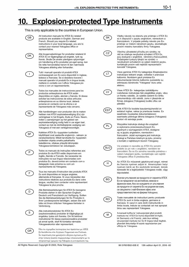
<10. EXPLOSION-PROTECTED TYPE INSTRUMENTS> 10-1
All Rights Reserved. Copyright © 2003, Rota Yokogawa IM 01R01B02-00E-E 13th edition April 01, 2016 -00
10. Explosion-protected Type InstrumentsThis is only applicable to the countries in European Union.
GB
DK
I
E
NL
SF
P
F
D
S
LT
LV
PL
EST
SLO
H
BG
RO
M
CZ
SK
GR
<10. EXPLOSION-PROTECTED TYPE INSTRUMENTS>10-2
All Rights Reserved. Copyright © 2003, Rota YokogawaIM 01R01B02-00E-E 13th edition April 01, 2016 -00
10.1 General
• Only trained persons may use the instrument in industrial location. • The instrument modification or parts replacement by other than an authorized Representative of Yokogawa is prohibited and will void the certification.
• Electrostatic charge on painted or other non- metallic surfaces may cause an explosion hazard. Avoid any actions that cause the generation of electrostatic charge, such as rubbing with a dry
cloth on painted surface of the indicator or on potting of electronic transmitter.
• If the meter is mounted in an area where the use of category 2D apparatus is required, it shall be installed in such a way that the risk from electrostatic discharges and propagating brush discharges
caused by rapid flow of dust is avoided.
10.1.1 Intrinsic safety
To ensure intrinsic safety it is not permitted to repair or to modify the electronic transmitter, the display, the limit switches or the calibration EEPROM.
The electronic transmitters type -E /KS1, -H /KS1, -E /KS2, -H /KS2, -E /KS3, -H /KS3, -E /ES1, -H /ES1, -E /ES3, -H /ES3, -E /ES2, -H /ES2, -E /FS1, -H /FS1, -E /NS1, -H /NS1, -E /CS1, -H /CS1, -E /GS1, -H /GS1, -E /US1, -H /US1, as well as the limit switches option /Kx with option /KS1, /KS2, /KS3, /FS1, /CS1, /NS1, /GS1 are intrinsically safe devices.
Power supply for the electronic transmitter and transmitter relay for the limit switches are associated apparatus and should be installed outside any hazardous area.
The electronic transmitter must be connected to an intrinsically safe, certified power supply with a maximum voltage and output power below the maximum values of the electronic transmitter (refer to Technical data, in the concerning chapters). The combined internal inductance and capacity of the electronic transmitter and connecting cables must be less than the permitted external inductance and capacity of the power supply. Accordingly, the limit switches have to be connected to intrinsically safe, certified isolating switching amplifiers.
The relevant maximum safety values must be heeded at all times. Especially in the case of high fluid temperatures, heated metering tubes or heat radiation by heat tracing, make sure that the temperature in the indicator housing does not exceed the permissible maximum ambienttemperature of the transmitter (refer to Technical data, chapter 9).
10.1.2 Flame proof
In the RAMC with option /KF1, /EF1, /NF1, /GF1 the transmitter and the limit switches are mounted in a flame proof housing.
Wait 2 minutes after switching power off before opening the cover.
The cover can only be opened after loosing the safety screw. After closing the cover the safety screw must be fixed before switching power on.The RAMC with option /KF1, /EF1, /NF1, /GF1 shall be connected up via suitable cable glands and / or conduit systems that satisfy the requirements of EN 50018 or 60079-1 sections 13.1 and 13.2 and for which a separate
test certificate is available. Cable glands and entry fittings (screwed conduit entries) as well as blanking plugs
of simple design may not be used. On connection of the RAMC /KF1, /EF1, /NF1, /GF1 using a conduit entry approved for the purpose, the associated sealing facility must be arranged directly on the housing.
Unused openings must be closed off as defined in EN 60079-1 section 11.9 (e.g. certified blanking elements).The RAMC with option /KF1, /EF1, /NF1, /GF1 shall be connected to the local equipollently grounding system.
Especially in the case of high fluid temperatures, heated metering tubes or heat radiation by heat tracing, make sure that the temperature in the indicator housing does not exceed the permissible maximum ambienttemperature of the transmitter (refer to Technical data, chapter 9).
WARNING
WARNING
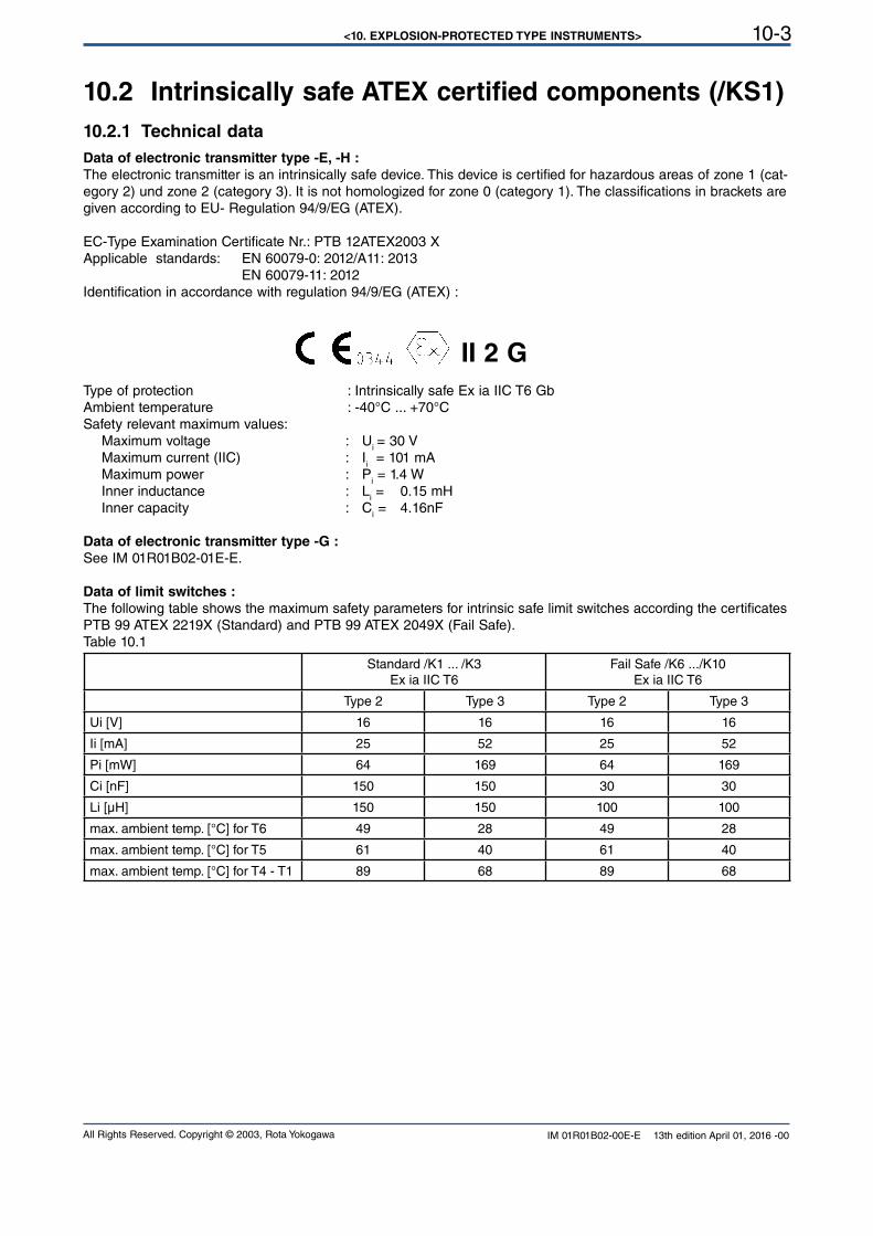
<10. EXPLOSION-PROTECTED TYPE INSTRUMENTS> 10-3
All Rights Reserved. Copyright © 2003, Rota Yokogawa IM 01R01B02-00E-E 13th edition April 01, 2016 -00
10.2 Intrinsically safe ATEX certified components (/KS1)
10.2.1 Technical data
Data of electronic transmitter type -E, -H :
The electronic transmitter is an intrinsically safe device. This device is certified for hazardous areas of zone 1 (cat-egory 2) und zone 2 (category 3). It is not homologized for zone 0 (category 1). The classifications in brackets are given according to EU- Regulation 94/9/EG (ATEX).
EC-Type Examination Certificate Nr.: PTB 12ATEX2003 X Applicable standards: EN 60079-0: 2012/A11: 2013 EN 60079-11: 2012Identification in accordance with regulation 94/9/EG (ATEX) :
II 2 G
Type of protection : Intrinsically safe Ex ia IIC T6 GbAmbient temperature : -40°C ... +70°CSafety relevant maximum values: Maximum voltage : U
i = 30 V
Maximum current (IIC) : Ii = 101 mA
Maximum power : Pi = 1.4 W
Inner inductance : Li = 0.15 mH
Inner capacity : Ci = 4.16nF
Data of electronic transmitter type -G :
See IM 01R01B02-01E-E.
Data of limit switches :
The following table shows the maximum safety parameters for intrinsic safe limit switches according the certificates
PTB 99 ATEX 2219X (Standard) and PTB 99 ATEX 2049X (Fail Safe).Table 10.1
Standard /K1 ... /K3Ex ia IIC T6
Fail Safe /K6 .../K10Ex ia IIC T6
Type 2 Type 3 Type 2 Type 3
Ui [V] 16 16 16 16
Ii [mA] 25 52 25 52
Pi [mW] 64 169 64 169
Ci [nF] 150 150 30 30
Li [µH] 150 150 100 100
max. ambient temp. [°C] for T6 49 28 49 28
max. ambient temp. [°C] for T5 61 40 61 40
max. ambient temp. [°C] for T4 - T1 89 68 89 68
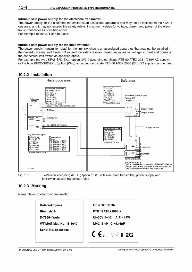
<10. EXPLOSION-PROTECTED TYPE INSTRUMENTS>10-4
All Rights Reserved. Copyright © 2003, Rota YokogawaIM 01R01B02-00E-E 13th edition April 01, 2016 -00
Rota Yokogawa
Rheinstr. 8
D-79664 Wehr
WT-MAG Mat. No. 16-8040
Serial No, xxxxxxxx
Ex ia IIC T6 Gb
PTB 12ATEX2003 X
Ui=30V Ii=101mA Pi=1.4W
Li=0.15mH Ci=4.16nF
II 2G
10.2.2 Installation
Intrinsic safe power supply for the electronic transmitter :
The power supply for the electronic transmitter is an associated apparatus that may not be installed in the hazard-
ous area, and it may not exceed the safety relevant maximum values for voltage, current and power of the elec-
tronic transmitter as specified above.
For example option /UT can be used.
Intrinsic safe power supply for the limit switches :
The power supply (transmitter relay) for the limit switches is an associated apparatus that may not be installed in the hazardous area, and it may not exceed the safety relevant maximum values for voltage, current and power of the connected limit switch as specified above.
For example the type KFA6-SR2-Ex... (option (W2_) according certificate PTB 00 ATEX 2081 (230V AC supply)or the type KFD2-SR2-Ex... (option (W4_) according certificate PTB 00 ATEX 2080 (24V DC supply) can be used.
Fig. 10.1 Ex-Version according ATEX (Option /KS1) with electronic transmitter, power supply and limit switches with transmitter relay
15
4
6
3
1
14
12
1011
87
9
1211
109
I -
I +
L/+N/-O -
O+Output 4-20mA
O+H Output HART
U
F
G
RAMC
A
Supply 230V AC
KFA6-SR2-Ex2.W
Option: /W2B two channels: KFA6-SR2-Ex2.WTransmitter relay
Limit MIN
Limit MAX
Option / Kn
Rotameter
4-20mA
Max
Min
Limit switch
EN 60947-5-6 (Namur)
One channel connection like limit MAX
I = 101mAP = 1.4WC = 4.16nF
U = 30V
L = 0.15mH
Transmitter WT-MAGEx ia IIC T6Gb
PTB 12 ATEX 2003
Tamax = 70°C
Tamax = Temperature in indicator
C = 150nF
Ex ia IIC T6
L = 0.15uH
SC 3.5-NO
P = 64mW
I = 25mAU = 16V
Temperature
T4 Tamax = 89°CT3 Tamax = 89°CT2 Tamax = 89°CT1 Tamax = 89°C
Class
T5 Tamax = 61°CT6 Tamax = 49°C
PTB 99 ATEX 2219 X
PTB 00 ATEX 2018
Transmitter power supply
Option: /UT
Option: /W2A one channel: KF A6-SR2-Ex1.W
C = 2320nF
I = 19.1mAP = 51mW
U = 10.6V
L = 97mH
PTB 00ATEX 2081
[Ex ia]) IICKFA6-SR2-Ex2.W
RN221N-B1
RN221N-B1
Tamax = 50°C
C = 86nFL = 5.2mH
U = 27.3V
P = 0.597W
[Ex ia] IIC
I = 87.6mAo
oo
oo
e.g. Standard Type 2
-
+
-
+
-
+
~ ~
+-
+-
i
ii
i
iii
i
i
o
oo
oo
F4.EPS
i
Hazardous area Safe area
10.2.3 Marking
Name plates of electronic transmitter :
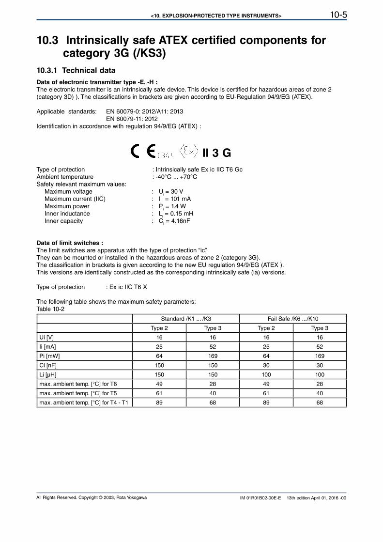
<10. EXPLOSION-PROTECTED TYPE INSTRUMENTS> 10-5
All Rights Reserved. Copyright © 2003, Rota Yokogawa IM 01R01B02-00E-E 13th edition April 01, 2016 -00
10.3 Intrinsically safe ATEX certified components for category 3G (/KS3)
10.3.1 Technical data
Data of electronic transmitter type -E, -H :
The electronic transmitter is an intrinsically safe device. This device is certified for hazardous areas of zone 2 (category 3D) ). The classifications in brackets are given according to EU-Regulation 94/9/EG (ATEX).
Applicable standards: EN 60079-0: 2012/A11: 2013 EN 60079-11: 2012Identification in accordance with regulation 94/9/EG (ATEX) :
II 3 G
Type of protection : Intrinsically safe Ex ic IIC T6 GcAmbient temperature : -40°C ... +70°CSafety relevant maximum values: Maximum voltage : U
i = 30 V
Maximum current (IIC) : Ii = 101 mA
Maximum power : Pi = 1.4 W
Inner inductance : Li = 0.15 mH
Inner capacity : Ci = 4.16nF
Data of limit switches :
The limit switches are apparatus with the type of protection “ic”.They can be mounted or installed in the hazardous areas of zone 2 (category 3G).The classification in brackets is given according to the new EU regulation 94/9/EG (ATEX ).This versions are identically constructed as the corresponding intrinsically safe (ia) versions.
Type of protection : Ex ic IIC T6 X
The following table shows the maximum safety parameters:Table 10-2
Standard /K1 ... /K3 Fail Safe /K6 .../K10
Type 2 Type 3 Type 2 Type 3
Ui [V] 16 16 16 16
Ii [mA] 25 52 25 52
Pi [mW] 64 169 64 169
Ci [nF] 150 150 30 30
Li [µH] 150 150 100 100
max. ambient temp. [°C] for T6 49 28 49 28
max. ambient temp. [°C] for T5 61 40 61 40
max. ambient temp. [°C] for T4 - T1 89 68 89 68
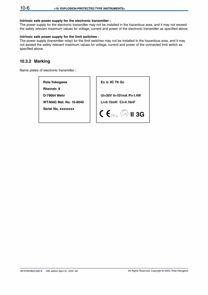
<10. EXPLOSION-PROTECTED TYPE INSTRUMENTS>10-6
All Rights Reserved. Copyright © 2003, Rota YokogawaIM 01R01B02-00E-E 13th edition April 01, 2016 -00
Rota Yokogawa
Rheinstr. 8
D-79664 Wehr
WT-MAG Mat. No. 16-8040
Serial No, xxxxxxxx
Ex ic IIC T6 Gc
Ui=30V Ii=101mA Pi=1.4W
Li=0.15mH Ci=4.16nF
II 3G
Intrinsic safe power supply for the electronic transmitter :
The power supply for the electronic transmitter may not be installed in the hazardous area, and it may not exceed the safety relevant maximum values for voltage, current and power of the electronic transmitter as specified above.
Intrinsic safe power supply for the limit switches :
The power supply (transmitter relay) for the limit switches may not be installed in the hazardous area, and it may not exceed the safety relevant maximum values for voltage, current and power of the connected limit switch as specified above.
10.3.2 Marking
Name plates of electronic transmitter :
<10. EXPLOSION-PROTECTED TYPE INSTRUMENTS> 10-7
All Rights Reserved. Copyright © 2003, Rota Yokogawa IM 01R01B02-00E-E 13th edition April 01, 2016 -00
10.4 Intrinsically safe IECEx- certified components (/ES1)
10.4.1 Technical data
Data of electronic transmitter type -E, -H :
The electronic transmitter is an intrinsically safe device. This device is certified for hazardous areas of zone 1 (category 2) und zone 2 (category 3). It is not homologized for zone 0 (category 1).
Certificate Nr.: IECEx PTB 12.0020 XApplicable standards: IEC 60079-0: 2011 edition 6
IEC 60079-11: 2011 edition 6
Type of protection : Intrinsically safe Ex ia IIC T6 GbAmbient temperature : -40°C ... +70°CSafety relevant maximum values: Maximum voltage : U
i = 30 V
Maximum current (IIC) : Ii = 101 mA
Maximum power : Pi = 1.4 W
Inner inductance : Li = 0.15 mH
Inner capacity : Ci = 4.16nF
Data of limit switches :
The following table shows the maximum safety parameters for intrinsic safe limit switches according the certificates
IECEx PTB 11.0091X (Standard) and IECEx PTB 11.0092X (Fail Safe).Table 10.3
Standard /K1 ... /K3Ex ia IIC T6
Fail Safe /K6 .../K10Ex ia IIC T6
Type 2 Type 3 Type 2 Type 3
Ui [V] 16 16 16 16
Ii [mA] 25 52 25 52
Pi [mW] 64 169 64 169
Ci [nF] 150 150 30 30
Li [µH] 150 150 100 100
max. ambient temp. [°C] for T6 49 28 49 28
max. ambient temp. [°C] for T5 61 40 61 40
max. ambient temp. [°C] for T4 - T1 89 68 89 68
Intrinsic safe power supply for the electronic transmitter :
The power supply for the electronic transmitter is an associated apparatus that may not be installed in the hazard-
ous area, and it may not exceed the safety relevant maximum values for voltage, current and power of the elec-
tronic transmitter as specified above.
For example option /UT can be used.
Intrinsic safe power supply for the limit switches :
The power supply (transmitter relay) for the limit switches is an associated apparatus that may not be installed in the hazardous area, and it may not exceed the safety relevant maximum values for voltage, current and power of the connected limit switch as specified above.
For example the type KFA6-SR2-Ex... (option (W2_) according certificate IECEx PTB 11.0031 (230V AC supply)or the type KFD2-SR2-Ex... (option (W4_) according certificate IECEx PTB 11.0032 (24V DC supply) can be used.
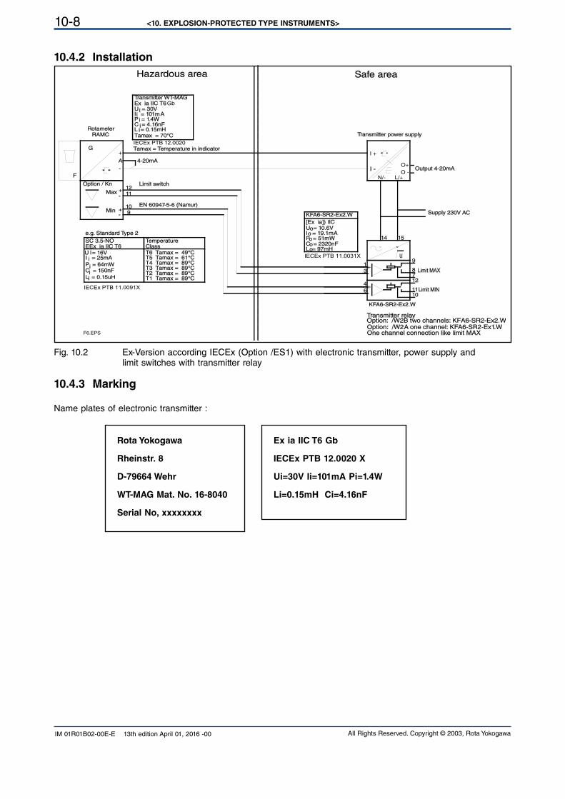
<10. EXPLOSION-PROTECTED TYPE INSTRUMENTS>10-8
All Rights Reserved. Copyright © 2003, Rota YokogawaIM 01R01B02-00E-E 13th edition April 01, 2016 -00
Rota Yokogawa
Rheinstr. 8
D-79664 Wehr
WT-MAG Mat. No. 16-8040
Serial No, xxxxxxxx
Ex ia IIC T6 Gb
IECEx PTB 12.0020 X
Ui=30V Ii=101mA Pi=1.4W
Li=0.15mH Ci=4.16nF
10.4.2 Installation
Fig. 10.2 Ex-Version according IECEx (Option /ES1) with electronic transmitter, power supply and limit switches with transmitter relay
15
4
6
3
1
14
12
1011
87
9
1211
109
I -
I +
L/+N/-O -
O+Output 4-20mA
U
F
G
RAMC
A
Supply 230V AC
KFA6-SR2-Ex2.W
Option: /W2B two channels: KFA6-SR2-Ex2.WTransmitter relay
Limit MIN
Limit MAX
Option / Kn
Rotameter
4-20mA
Max
Min
Limit switch
EN 60947-5-6 (Namur)
One channel connection like limit MAX
I = 101mAP = 1.4WC = 4.16nF
U = 30V
L = 0.15mH
Ex ia IIC T6Gb
IECEx PTB 12.0020
Tamax = 70°C
Tamax = Temperature in indicator
C = 150nF
EEx ia IIC T6
L = 0.15uH
SC 3.5-NO
P = 64mW
I = 25mAU = 16V
Temperature Class
Transmitter power supply
Option: /W2A one channel: KF A6-SR2-Ex1.W
KFA6-SR2-Ex2.W
IECEx PTB 11.0031X
IECEx PTB 11.0091X
Transmitter WT-MAG
T4 Tamax = 89°CT3 Tamax = 89°CT2 Tamax = 89°CT1 Tamax = 89°C
T5 Tamax = 61°CT6 Tamax = 49°C
-
+
-
+
-
+
~ ~
+-
+-
i
ii
i
iii
i
i
F6.EPS
i
C = 2320nF
I = 19.1mAP = 51mW
U = 10.6V
L = 97mH
[Ex ia]) IIC
o
oo
oo
Hazardous area Safe area
e.g. Standard Type 2
10.4.3 Marking
Name plates of electronic transmitter :
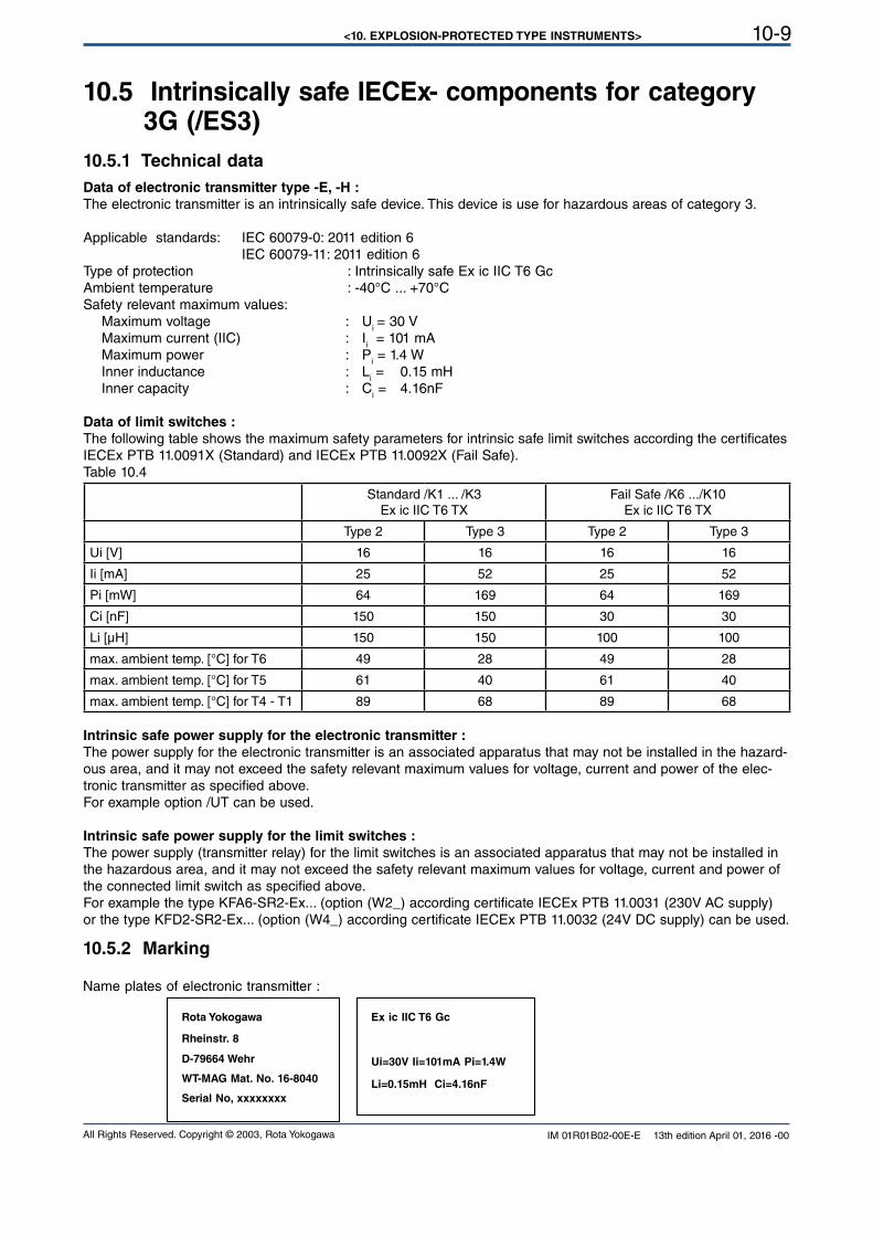
<10. EXPLOSION-PROTECTED TYPE INSTRUMENTS> 10-9
All Rights Reserved. Copyright © 2003, Rota Yokogawa IM 01R01B02-00E-E 13th edition April 01, 2016 -00
10.5 Intrinsically safe IECEx- components for category 3G (/ES3)
10.5.1 Technical data
Data of electronic transmitter type -E, -H :
The electronic transmitter is an intrinsically safe device. This device is use for hazardous areas of category 3.
Applicable standards: IEC 60079-0: 2011 edition 6
IEC 60079-11: 2011 edition 6
Type of protection : Intrinsically safe Ex ic IIC T6 GcAmbient temperature : -40°C ... +70°CSafety relevant maximum values: Maximum voltage : U
i = 30 V
Maximum current (IIC) : Ii = 101 mA
Maximum power : Pi = 1.4 W
Inner inductance : Li = 0.15 mH
Inner capacity : Ci = 4.16nF
Data of limit switches :
The following table shows the maximum safety parameters for intrinsic safe limit switches according the certificates
IECEx PTB 11.0091X (Standard) and IECEx PTB 11.0092X (Fail Safe).Table 10.4
Standard /K1 ... /K3Ex ic IIC T6 TX
Fail Safe /K6 .../K10Ex ic IIC T6 TX
Type 2 Type 3 Type 2 Type 3
Ui [V] 16 16 16 16
Ii [mA] 25 52 25 52
Pi [mW] 64 169 64 169
Ci [nF] 150 150 30 30
Li [µH] 150 150 100 100
max. ambient temp. [°C] for T6 49 28 49 28
max. ambient temp. [°C] for T5 61 40 61 40
max. ambient temp. [°C] for T4 - T1 89 68 89 68
Intrinsic safe power supply for the electronic transmitter :
The power supply for the electronic transmitter is an associated apparatus that may not be installed in the hazard-
ous area, and it may not exceed the safety relevant maximum values for voltage, current and power of the elec-
tronic transmitter as specified above.
For example option /UT can be used.
Intrinsic safe power supply for the limit switches :
The power supply (transmitter relay) for the limit switches is an associated apparatus that may not be installed in the hazardous area, and it may not exceed the safety relevant maximum values for voltage, current and power of the connected limit switch as specified above.
For example the type KFA6-SR2-Ex... (option (W2_) according certificate IECEx PTB 11.0031 (230V AC supply)or the type KFD2-SR2-Ex... (option (W4_) according certificate IECEx PTB 11.0032 (24V DC supply) can be used.
Rota Yokogawa
Rheinstr. 8
D-79664 Wehr
WT-MAG Mat. No. 16-8040
Serial No, xxxxxxxx
Ex ic IIC T6 Gc
Ui=30V Ii=101mA Pi=1.4W
Li=0.15mH Ci=4.16nF
10.5.2 Marking
Name plates of electronic transmitter :
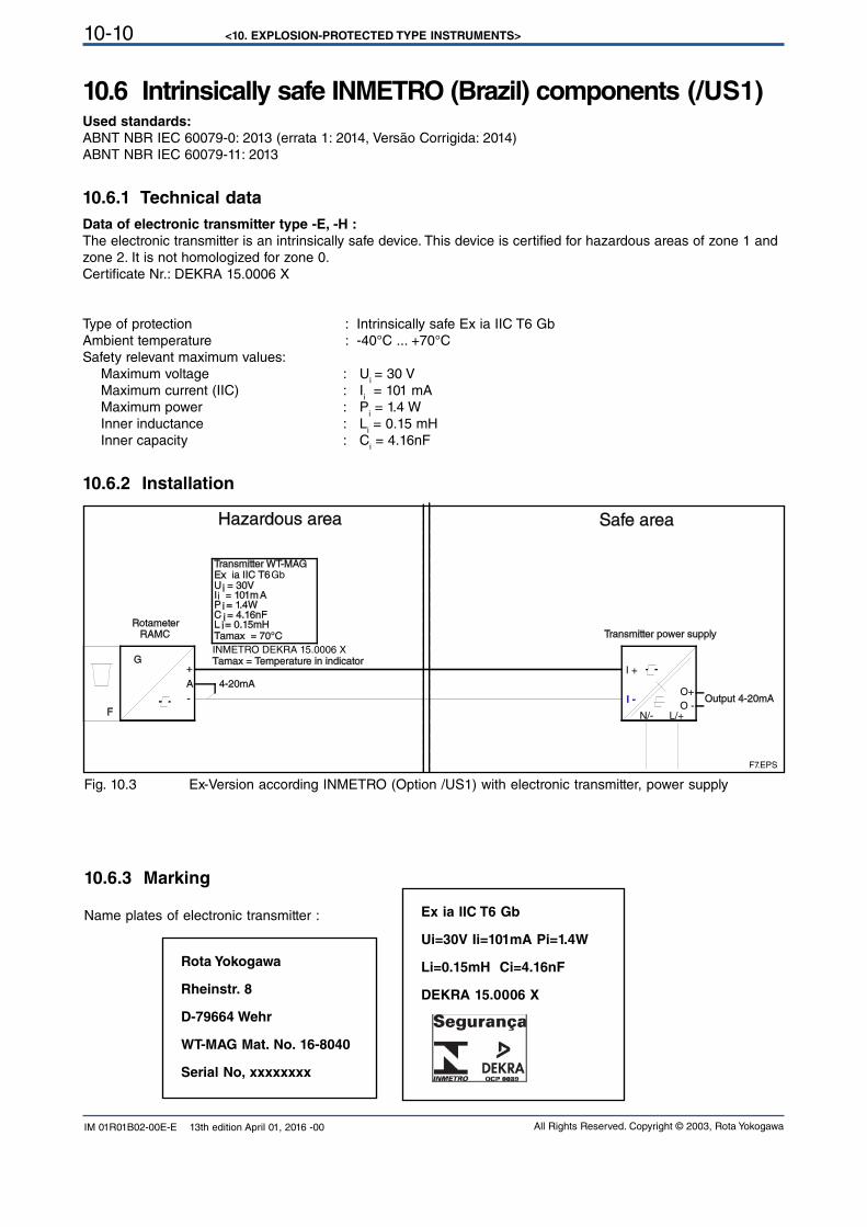
<10. EXPLOSION-PROTECTED TYPE INSTRUMENTS>10-10
All Rights Reserved. Copyright © 2003, Rota YokogawaIM 01R01B02-00E-E 13th edition April 01, 2016 -00
10.6.3 Marking
Name plates of electronic transmitter :
10.6 Intrinsically safe INMETRO (Brazil) components (/US1)Used standards:
ABNT NBR IEC 60079-0: 2013 (errata 1: 2014, Versão Corrigida: 2014)ABNT NBR IEC 60079-11: 2013
10.6.1 Technical data
Data of electronic transmitter type -E, -H :
The electronic transmitter is an intrinsically safe device. This device is certified for hazardous areas of zone 1 and zone 2. It is not homologized for zone 0.
Certificate Nr.: DEKRA 15.0006 X
Type of protection : Intrinsically safe Ex ia IIC T6 GbAmbient temperature : -40°C ... +70°CSafety relevant maximum values: Maximum voltage : U
i = 30 V
Maximum current (IIC) : Ii = 101 mA
Maximum power : Pi = 1.4 W
Inner inductance : Li = 0.15 mH
Inner capacity : Ci = 4.16nF
10.6.2 Installation
Fig. 10.3 Ex-Version according INMETRO (Option /US1) with electronic transmitter, power supply
Rota Yokogawa
Rheinstr. 8
D-79664 Wehr
WT-MAG Mat. No. 16-8040
Serial No, xxxxxxxx
Ex ia IIC T6 Gb
Ui=30V Ii=101mA Pi=1.4W
Li=0.15mH Ci=4.16nF
DEKRA 15.0006 X
I -
I +
L/+N/-O -
O+Output 4-20mA
F
G
RAMC
A
Rotameter
4-20mA
I = 101mAP = 1.4WC = 4.16nF
U = 30V
L = 0.15mH
Ex ia IIC T6Gb
INMETRO DEKRA 15.0006 X
Tamax = 70°C
Tamax = Temperature in indicator
Transmitter power supply
Transmitter WT-MAG
-
+
i
ii
i
F7.EPS
i
Hazardous area Safe area
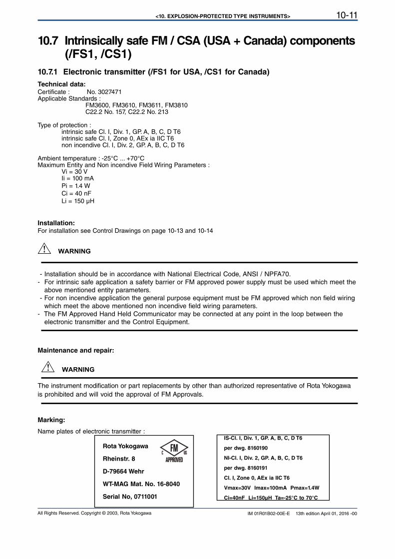
<10. EXPLOSION-PROTECTED TYPE INSTRUMENTS> 10-11
All Rights Reserved. Copyright © 2003, Rota Yokogawa IM 01R01B02-00E-E 13th edition April 01, 2016 -00
Installation:For installation see Control Drawings on page 10-13 and 10-14
WARNING
- Installation should be in accordance with National Electrical Code, ANSI / NPFA70. - For intrinsic safe application a safety barrier or FM approved power supply must be used which meet the above mentioned entity parameters.
- For non incendive application the general purpose equipment must be FM approved which non field wiring
which meet the above mentioned non incendive field wiring parameters.
- The FM Approved Hand Held Communicator may be connected at any point in the loop between the electronic transmitter and the Control Equipment.
Maintenance and repair:
WARNING
The instrument modification or part replacements by other than authorized representative of Rota Yokogawa is prohibited and will void the approval of FM Approvals.
Marking:
Name plates of electronic transmitter :IS-Cl. I, Div. 1, GP. A, B, C, D T6
per dwg. 8160190
NI-Cl. I, Div. 2, GP. A, B, C, D T6
per dwg. 8160191
Cl. I, Zone 0, AEx ia IIC T6
Vmax=30V Imax=100mA Pmax=1.4W
Ci=40nF Li=150µH Ta=-25°C to 70°C
Rota Yokogawa
Rheinstr. 8
D-79664 Wehr
WT-MAG Mat. No. 16-8040
Serial No, 0711001
10.7 Intrinsically safe FM / CSA (USA + Canada) components (/FS1, /CS1)
10.7.1 Electronic transmitter (/FS1 for USA, /CS1 for Canada)
Technical data: Certificate : No. 3027471Applicable Standards : FM3600, FM3610, FM3611, FM3810 C22.2 No. 157, C22.2 No. 213
Type of protection : intrinsic safe Cl. I, Div. 1, GP. A, B, C, D T6 intrinsic safe Cl. I, Zone 0, AEx ia IIC T6 non incendive Cl. I, Div. 2, GP. A, B, C, D T6
Ambient temperature : -25°C ... +70°CMaximum Entity and Non incendive Field Wiring Parameters : Vi = 30 V Ii = 100 mA
Pi = 1.4 W Ci = 40 nF Li = 150 µH
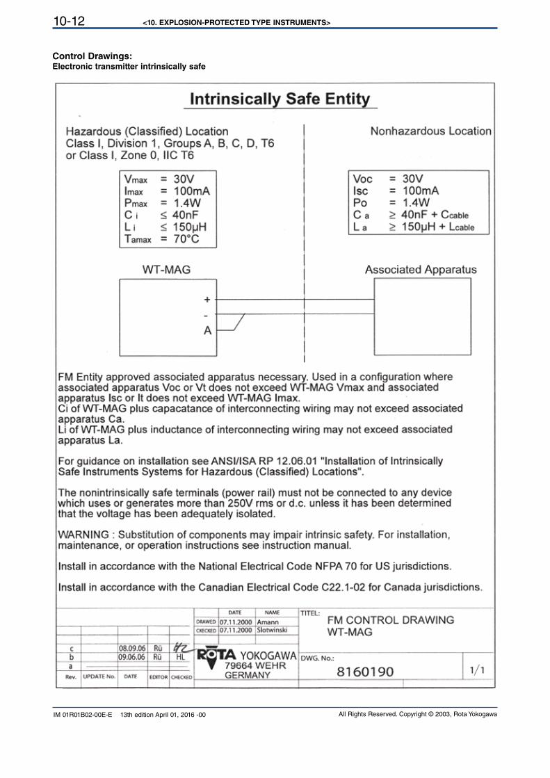
<10. EXPLOSION-PROTECTED TYPE INSTRUMENTS>10-12
All Rights Reserved. Copyright © 2003, Rota YokogawaIM 01R01B02-00E-E 13th edition April 01, 2016 -00
Control Drawings:Electronic transmitter intrinsically safe
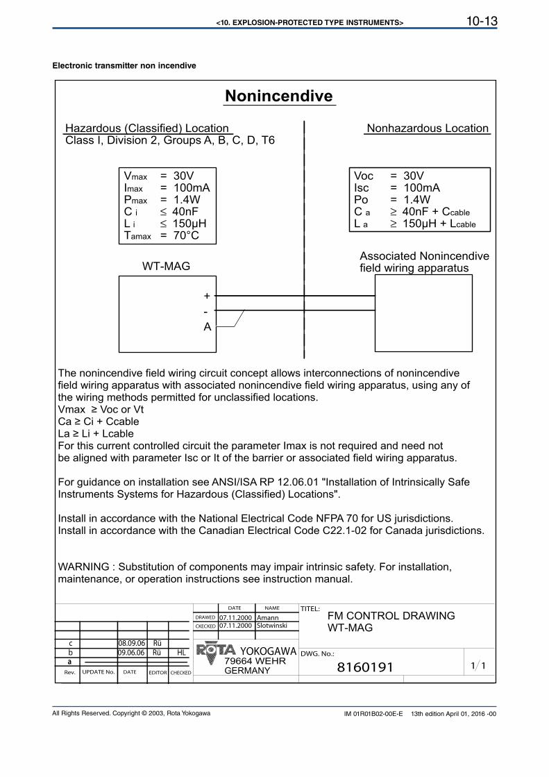
<10. EXPLOSION-PROTECTED TYPE INSTRUMENTS> 10-13
All Rights Reserved. Copyright © 2003, Rota Yokogawa IM 01R01B02-00E-E 13th edition April 01, 2016 -00
Electronic transmitter non incendive
1 18160191
FM CONTROL DRAWINGWT-MAG
Amann07.11.2000Slotwinski07.11.2000CKECKED
DRAWED
UPDATE No.Rev.
aaDATE EDITOR CHECKED
TITEL:NAMEDATE
DWG. No.:
79664 WEHRYOKOGAWA
GERMANY
b 09.06.06 Rü HL
Nonincendive
Hazardous (Classified) LocationClass I, Division 2, Groups A, B, C, D, T6
Nonhazardous Location
Vmax = 30VImax = 100mAPmax = 1.4WC i ≤ 40nFL i ≤ 150µHTamax = 70°C
Voc = 30VIsc = 100mAPo = 1.4WC a ≥ 40nF + Ccable
L a ≥ 150µH + Lcable
WT-MAGAssociated Nonincendivefield wiring apparatus
+
-
A
The nonincendive field wiring circuit concept allows interconnections of nonincendivefield wiring apparatus with associated nonincendive field wiring apparatus, using any ofthe wiring methods permitted for unclassified locations.Vmax ≥ Voc or Vt Ca ≥ Ci + Ccable La ≥ Li + LcableFor this current controlled circuit the parameter Imax is not required and need notbe aligned with parameter Isc or It of the barrier or associated field wiring apparatus.
For guidance on installation see ANSI/ISA RP 12.06.01 "Installation of Intrinsically SafeInstruments Systems for Hazardous (Classified) Locations".
Install in accordance with the National Electrical Code NFPA 70 for US jurisdictions.Install in accordance with the Canadian Electrical Code C22.1-02 for Canada jurisdictions.
WARNING : Substitution of components may impair intrinsic safety. For installation,maintenance, or operation instructions see instruction manual.
c 08.09.06 Rü
<10. EXPLOSION-PROTECTED TYPE INSTRUMENTS>10-14
All Rights Reserved. Copyright © 2003, Rota YokogawaIM 01R01B02-00E-E 13th edition April 01, 2016 -00
10.7.2 Limit switches option /K1 ... /K10 (/FS1 for USA)
Data of limit switches (FM-approval):
The limit switches are intrinsically safe devices. They are certified by Pepperl & Fuchs for: Intrinsically safe : Cl. I, Div. 1, GP. A, B, C, D T6 Ta=60°C Cl. II, Div. 1, GP. E, F, G Cl. III, Div. 1
Non incendive: Cl. I, Div. 2, GP. A, B, C, D T5 Ta=50°C Cl. II, Div. 1, GP. E, F, G Cl. III, Div. 1
Maximum Entity Field Wiring Parameters : see FM-control drawing 116-0165 on page 10-15 and 10-16 for intrinsic safety see FM-control drawing 116-0155 on page 10-17 for non incendive
10.7.3 Limit switches option /K1 ... /K3 (/CS1 for Canada)
Data of limit switches (CSA-approval):
The limit switches are intrinsically safe devices. They are certified by Pepperl & Fuchs for: Intrinsically safe : Cl. I, Div. 1, GP. A, B, C, D Cl. II, Div. 1, GP. E, F, G Cl. III, Div. 1
Maximum Entity Field Wiring Parameters : see CSA drawing 116-0047 on page 10-18 and 10-19
WARNING
Only in combination with power supply option /WxA or /WxB.
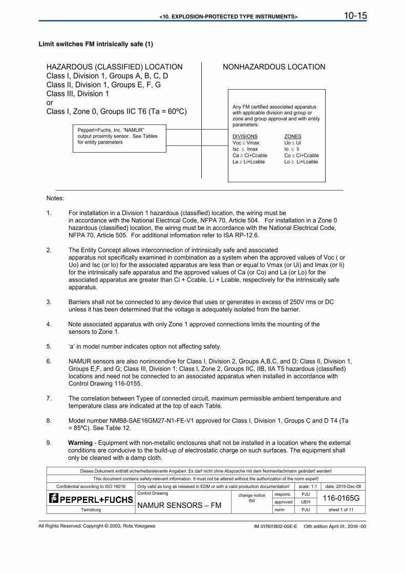
<10. EXPLOSION-PROTECTED TYPE INSTRUMENTS> 10-15
All Rights Reserved. Copyright © 2003, Rota Yokogawa IM 01R01B02-00E-E 13th edition April 01, 2016 -00
Limit switches FM intrisically safe (1)
Dieses Dokument enthält sicherheitsrelevante Angaben. Es darf nicht ohne Absprache mit dem Normenfachmann geändert werden!
This document contains safety-relevant information. It must not be altered without the authorization of the norm expert!
Confidential according to ISO 16016 Only valid as long as released in EDM or with a valid production documentation! scale: 1:1 date: 2015-Dec-08
Control Drawing
NAMUR SENSORS – FM
change notice tbd
respons. PJU 116-0165G
approved UEH Twinsburg norm PJU sheet 1 of 11
HAZARDOUS (CLASSIFIED) LOCATION NONHAZARDOUS LOCATION Class I, Division 1, Groups A, B, C, D Class II, Division 1, Groups E, F, G Class III, Division 1 or Class I, Zone 0, Groups IIC T6 (Ta = 60ºC)
Notes: 1. For installation in a Division 1 hazardous (classified) location, the wiring must be
in accordance with the National Electrical Code, NFPA 70, Article 504. For installation in a Zone 0 hazardous (classified) location, the wiring must be in accordance with the National Electrical Code, NFPA 70, Article 505. For additional information refer to ISA RP-12.6.
2. The Entity Concept allows interconnection of intrinsically safe and associated apparatus not specifically examined in combination as a system when the approved values of Voc ( or Uo) and Isc (or Io) for the associated apparatus are less than or equal to Vmax (or Ui) and Imax (or Ii) for the intrinsically safe apparatus and the approved values of Ca (or Co) and La (or Lo) for the associated apparatus are greater than Ci + Ccable, Li + Lcable, respectively for the intrinsically safe apparatus.
3. Barriers shall not be connected to any device that uses or generates in excess of 250V rms or DC unless it has been determined that the voltage is adequately isolated from the barrier.
4. Note associated apparatus with only Zone 1 approved connections limits the mounting of the
sensors to Zone 1. 5. ‘a’ in model number indicates option not affecting safety. 6. NAMUR sensors are also nonincendive for Class I, Division 2, Groups A,B,C, and D; Class II, Division 1,
Groups E,F, and G; Class III, Division 1; Class I, Zone 2, Groups IIC, IIB, IIA T5 hazardous (classified) locations and need not be connected to an associated apparatus when installed in accordance with Control Drawing 116-0155.
7. The correlation between Typee of connected circuit, maximum permissible ambient temperature and
temperature class are indicated at the top of each Table. 8. Model number NMB8-SAE16GM27-N1-FE-V1 approved for Class I, Division 1, Groups C and D T4 (Ta
= 85ºC). See Table 12. 9. Warning - Equipment with non-metallic enclosures shall not be installed in a location where the external
conditions are conducive to the build-up of electrostatic charge on such surfaces. The equipment shall only be cleaned with a damp cloth.
Pepperl+Fuchs, Inc. “NAMUR” output proximity sensor. See Tables for entity parameters
Any FM certified associated apparatus with applicable division and group or zone and group approval and with entity parameters: DIVISIONS ZONES
Voc Vmax Uo Ui
Isc Imax Io Ii
Ca Ci+Ccable Co Ci+Ccable
La Li+Lcable Lo Li+Lcable
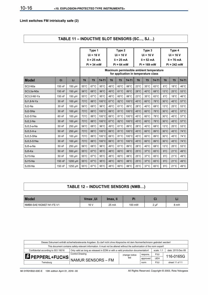
<10. EXPLOSION-PROTECTED TYPE INSTRUMENTS>10-16
All Rights Reserved. Copyright © 2003, Rota YokogawaIM 01R01B02-00E-E 13th edition April 01, 2016 -00
Limit switches FM intrisically safe (2)
Dieses Dokument enthält sicherheitsrelevante Angaben. Es darf nicht ohne Absprache mit dem Normenfachmann geändert werden!
This document contains safety-relevant information. It must not be altered without the authorization of the norm expert!
Confidential according to ISO 16016 Only valid as long as released in EDM or with a valid production documentation! scale: 1:1 date: 2015-Dec-08
Control Drawing
NAMUR SENSORS – FM
change notice tbd
respons. PJU 116-0165G
approved UEH Twinsburg norm PJU sheet 11 of 11
TABLE 11 – INDUCTIVE SLOT SENSORS (SC..., SJ…)
Type 1 Type 2 Type 3 Type 4
Ui = 16 V Ui = 16 V Ui = 16 V Ui = 16 V
Ii = 25 mA Ii = 25 mA Ii = 52 mA Ii = 76 mA
Pi = 34 mW Pi = 64 mW Pi = 169 mW Pi = 242 mW
Maximum permissible ambient temperature
for application in temperature class
Model Ci Li T6 T5 T4-T1 T6 T5 T4-T1 T6 T5 T4-T1 T6 T5 T4-T1
SC2-N0a 150 nF 150 µH 55°C 67°C 95°C 48°C 60°C 88°C 23°C 35°C 63°C 6°C 18°C 46°C
SC3,5a-N0a 150 nF 150 µH 56°C 68°C 96°C 49°C 61°C 89°C 28°C 40°C 68°C 13°C 25°C 53°C
SC3,5-N0-Ya 150 nF 150 µH 55°C 67°C 95°C 48°C 60°C 88°C 23°C 35°C 63°C 6°C 18°C 46°C
SJ1,8-N-Ya 30 nF 100 µH 73°C 88°C 100°C 67°C 82°C 100°C 45°C 60°C 78°C 30°C 45°C 57°C
SJ2-Na 30 nF 100 µH 56°C 68°C 96°C 49°C 61°C 89°C 28°C 40°C 68°C 13°C 25°C 53°C
SJ2-SNa 30 nF 100 µH 73°C 88°C 100°C 66°C 81°C 100°C 45°C 60°C 78°C 30°C 45°C 57°C
SJ2-S1Na 60 nF 100 µH 73°C 88°C 100°C 66°C 81°C 100°C 45°C 60°C 78°C 30°C 45°C 57°C
SJ2,2-Na 30 nF 100 µH 73°C 88°C 100°C 67°C 82°C 100°C 45°C 60°C 78°C 30°C 45°C 57°C
SJ3,5-a-Na 50 nF 250 µH 56°C 68°C 96°C 49°C 61°C 89°C 28°C 40°C 68°C 13°C 25°C 53°C
SJ3,5-H-a 50 nF 250 µH 73°C 88°C 100°C 66°C 81°C 100°C 45°C 60°C 89°C 30°C 45°C 74°C
SJ3,5-SNa 30 nF 100 µH 73°C 88°C 100°C 66°C 81°C 100°C 45°C 60°C 89°C 30°C 45°C 74°C
SJ3,5-S1Na 30 nF 100 µH 73°C 88°C 100°C 66°C 81°C 100°C 45°C 60°C 89°C 30°C 45°C 74°C
SJ5-a-Na 50 nF 250 µH 56°C 68°C 96°C 49°C 61°C 89°C 28°C 40°C 68°C 13°C 25°C 53°C
SJ5-Ka 50 nF 550 µH 55°C 67°C 95°C 48°C 60°C 88°C 25°C 37°C 65°C 9°C 21°C 49°C
SJ10-Na 50 nF 100 µH 55°C 67°C 95°C 48°C 60°C 88°C 25°C 37°C 65°C 9°C 21°C 49°C
SJ15-Na 150 nF 1200 µH 55°C 67°C 95°C 48°C 60°C 88°C 25°C 37°C 65°C 9°C 21°C 49°C
SJ30-Na 150 nF 1250 µH 55°C 67°C 95°C 48°C 60°C 88°C 25°C 37°C 65°C 9°C 21°C 49°C
TABLE 12 – INDUCTIVE SENSORS (NMB…)
Model Vmax ,Ui Imax, Ii Pi Ci Li
NMB8-SAE16GM27-N1-FE-V1 16 V 25 mA 100 mW 2 µF 8 mH
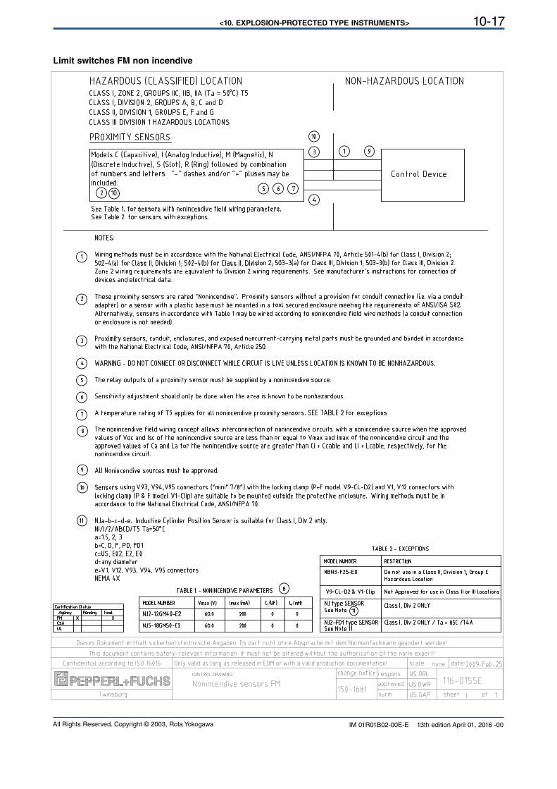
<10. EXPLOSION-PROTECTED TYPE INSTRUMENTS> 10-17
All Rights Reserved. Copyright © 2003, Rota Yokogawa IM 01R01B02-00E-E 13th edition April 01, 2016 -00
Limit switches FM non incendive
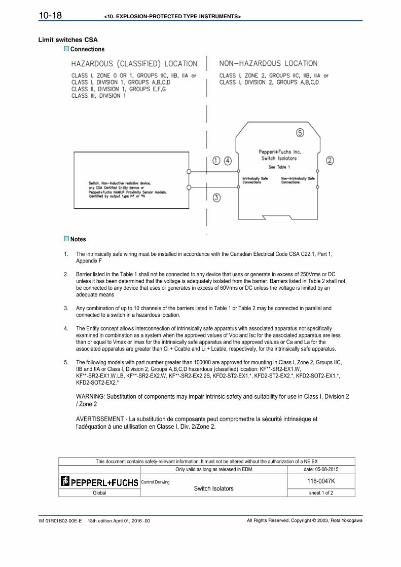
<10. EXPLOSION-PROTECTED TYPE INSTRUMENTS>10-18
All Rights Reserved. Copyright © 2003, Rota YokogawaIM 01R01B02-00E-E 13th edition April 01, 2016 -00
Limit switches CSA
This document contains safety-relevant information. It must not be altered without the authorization of a NE EX
Only valid as long as released in EDM date: 05-08-2015
Control Drawing
Switch Isolators 116-0047K
Global sheet 1 of 2
Connections
Notes
1. The intrinsically safe wiring must be installed in accordance with the Canadian Electrical Code CSA C22.1, Part 1,
Appendix F
2. Barrier listed in the Table 1 shall not be connected to any device that uses or generate in excess of 250Vrms or DC unless it has been determined that the voltage is adequately isolated from the barrier. Barriers listed in Table 2 shall not be connected to any device that uses or generates in excess of 60Vrms or DC unless the voltage is limited by an adequate means
3. Any combination of up to 10 channels of the barriers listed in Table 1 or Table 2 may be connected in parallel and
connected to a switch in a hazardous location.
4. The Entity concept allows interconnection of intrinsically safe apparatus with associated apparatus not specifically examined in combination as a system when the approved values of Voc and Isc for the associated apparatus are less than or equal to Vmax or Imax for the intrinsically safe apparatus and the approved values or Ca and La for the associated apparatus are greater than Ci + Ccable and Li + Lcable, respectively, for the intrinsically safe apparatus.
5. The following models with part number greater than 100000 are approved for mounting in Class I, Zone 2, Groups IIC,
IIB and IIA or Class I, Division 2, Groups A,B,C,D hazardous (classified) location: KF**-SR2-EX1.W, KF**-SR2-EX1.W.LB, KF**-SR2-EX2.W, KF**-SR2-EX2.2S, KFD2-ST2-EX1.*, KFD2-ST2-EX2.*, KFD2-SOT2-EX1.*, KFD2-SOT2-EX2.*
WARNING: Substitution of components may impair intrinsic safety and suitability for use in Class I, Division 2 / Zone 2
AVERTISSEMENT - La substitution de composants peut compromettre la sécurité intrinsèque et l'adéquation à une utilisation en Classe I, Div. 2/Zone 2.
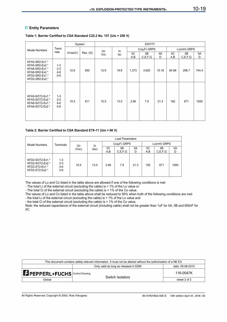
<10. EXPLOSION-PROTECTED TYPE INSTRUMENTS> 10-19
All Rights Reserved. Copyright © 2003, Rota Yokogawa IM 01R01B02-00E-E 13th edition April 01, 2016 -00
This document contains safety-relevant information. It must not be altered without the authorization of a NE EX
Only valid as long as released in EDM date: 05-08-2015
Control Drawing
Switch Isolators 116-0047K
Global sheet 2 of 2
Entity Parameters
Table 1: Barrier Certified to CSA Standard C22.2 No. 157 (Um = 250 V)
Model Numbers Terminals
System ENTITY
Vmax(V) Res. (Ω) Uo Voc
Io Isc
Co(µF) GRPS Lo(mH) GRPS
IIC A,B
IIB C,E,F,G
IIA D
IIC A,B
IIB C,E,F,G
IIA D
KFA5-SR2-Ex1.* KFA5-SR2-Ex2.* KFA6-SR2-Ex1.* KFA6-SR2-Ex2.* KFD2-SR2-Ex1.* KFD2-SR2-Ex2.*
1-3 2-3 4-6 5-6
12.6 650 12.9 19.8 1.273 3.820 10.18 84.88 298.7 744.4
KFA5-SOT2-Ex1.* KFA5-SOT2-Ex2.* KFA6-SOT2-Ex1.* KFA6-SOT2-Ex2.*
1-3 2-3 4-6 5-6
10.5 811 10.5 13.0 2.66 7.9 21.3 192 671 1000
Table 2: Barrier Certified to CSA Standard E79-11 (Um = 60 V)
Model Numbers Terminals
Load Parameters
Uo (Voc)
Io (Isc)
Co(µF) GRPS Lo(mH) GRPS
IIC A,B
IIB C,E,F,G
IIA D
IIC A,B
IIB C,E,F,G
IIA D
KFD2-SOT2-Ex1.* KFD2-SOT2-Ex2.* KFD2-ST2-Ex1.* KFD2-ST2-Ex2.*
1-3 2-3 4-6 5-6
10.5 13.0 2.66 7.9 21.3 192 671 1000
The values of Lo and Co listed in the table above are allowed if one of the following conditions is met: - The total Li of the external circuit (excluding the cable) is < 1% of the Lo value or - The total Ci of the external circuit (excluding the cable) is < 1% of the Co value. The values of Lo and Co listed in the table above shall be reduced to 50% when both of the following conditions are met: - the total Li of the external circuit (excluding the cable) is > 1% of the Lo value and - the total Ci of the external circuit (excluding the cable) is > 1% of the Co value. Note: the reduced capacitance of the external circuit (including cable) shall not be greater than 1uF for IIA, IIB and 600nF for IIC.
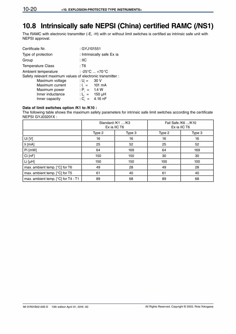
<10. EXPLOSION-PROTECTED TYPE INSTRUMENTS>10-20
All Rights Reserved. Copyright © 2003, Rota YokogawaIM 01R01B02-00E-E 13th edition April 01, 2016 -00
10.8 Intrinsically safe NEPSI (China) certified RAMC (/NS1)The RAMC with electronic transmitter (-E, -H) with or without limit switches is certified as intrinsic safe unit with NEPSI approval.
Certificate Nr. : GYJ101551
Type of protection : Intrinsically safe Ex ia
Group : IIC
Temperature Class : T6
Ambient temperature : -25°C ... +70 °CSafety relevant maximum values of electronic transmitter :
Maximum voltage : Ui = 30 V
Maximum current : Ii = 101 mA
Maximum power : Pi = 1.4 W
Inner inductance : Li = 150 µH
Inner capacity : Ci = 4.16 nF
Data of limit switches option /K1 to /K10 :
The following table shows the maximum safety parameters for intrinsic safe limit switches according the certificate NEPSI GYJ03201X :
Standard /K1 ... /K3Ex ia IIC T6
Fail Safe /K6 .../K10Ex ia IIC T6
Type 2 Type 3 Type 2 Type 3
Ui [V] 16 16 16 16
Ii [mA] 25 52 25 52
Pi [mW] 64 169 64 169
Ci [nF] 150 150 30 30
Li [µH] 150 150 100 100
max. ambient temp. [°C] for T6 49 28 49 28
max. ambient temp. [°C] for T5 61 40 61 40
max. ambient temp. [°C] for T4 - T1 89 68 89 68
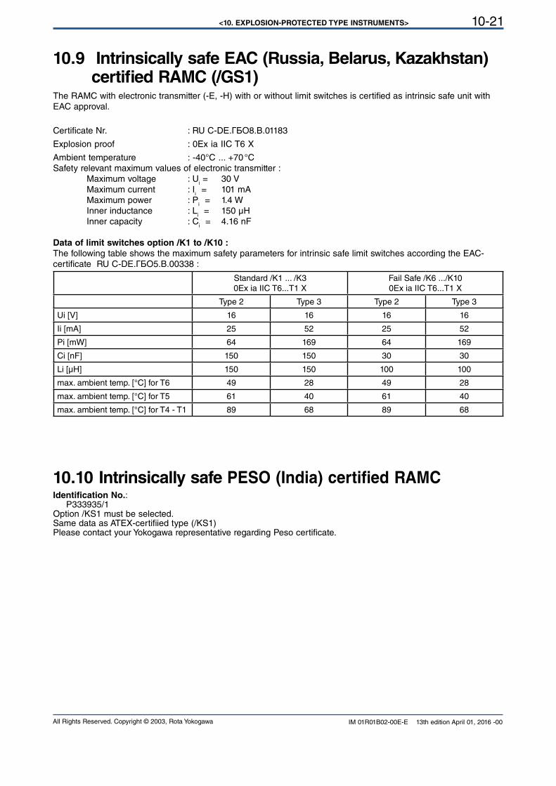
<10. EXPLOSION-PROTECTED TYPE INSTRUMENTS> 10-21
All Rights Reserved. Copyright © 2003, Rota Yokogawa IM 01R01B02-00E-E 13th edition April 01, 2016 -00
10.9 Intrinsically safe EAC (Russia, Belarus, Kazakhstan)certified RAMC (/GS1)
The RAMC with electronic transmitter (-E, -H) with or without limit switches is certified as intrinsic safe unit with EAC approval.
Certificate Nr. : RU С-DЕ.ГБО8.В.01183
Explosion proof : 0Ex ia IIC T6 X
Ambient temperature : -40°C ... +70 °CSafety relevant maximum values of electronic transmitter : Maximum voltage : U
i = 30 V
Maximum current : Ii = 101 mA
Maximum power : Pi = 1.4 W
Inner inductance : Li = 150 µH
Inner capacity : Ci = 4.16 nF
Data of limit switches option /K1 to /K10 :
The following table shows the maximum safety parameters for intrinsic safe limit switches according the EAC-certificate RU С-DЕ.ГБО5.В.00338 :
Standard /K1 ... /K30Ex ia IIC T6...T1 X
Fail Safe /K6 .../K100Ex ia IIC T6...T1 X
Type 2 Type 3 Type 2 Type 3
Ui [V] 16 16 16 16
Ii [mA] 25 52 25 52
Pi [mW] 64 169 64 169
Ci [nF] 150 150 30 30
Li [µH] 150 150 100 100
max. ambient temp. [°C] for T6 49 28 49 28
max. ambient temp. [°C] for T5 61 40 61 40
max. ambient temp. [°C] for T4 - T1 89 68 89 68
10.10 Intrinsically safe PESO (India) certified RAMCIdentification No.: P333935/1Option /KS1 must be selected.Same data as ATEX-certifiied type (/KS1)Please contact your Yokogawa representative regarding Peso certificate.
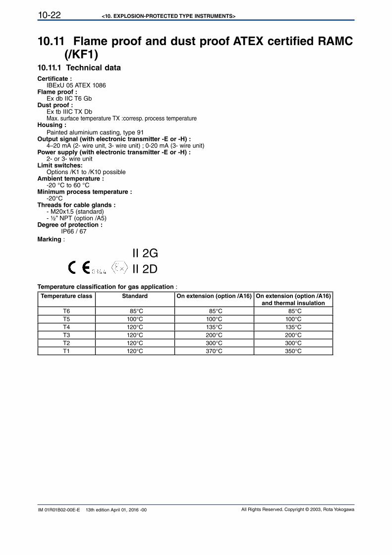
<10. EXPLOSION-PROTECTED TYPE INSTRUMENTS>10-22
All Rights Reserved. Copyright © 2003, Rota YokogawaIM 01R01B02-00E-E 13th edition April 01, 2016 -00
10.11 Flame proof and dust proof ATEX certified RAMC (/KF1)
10.11.1 Technical data
Certificate : IBExU 05 ATEX 1086Flame proof : Ex db IIC T6 Gb Dust proof : Ex tb IIIC TX Db Max. surface temperature TX :corresp. process temperature Housing :
Painted aluminium casting, type 91Output signal (with electronic transmitter -E or -H) : 4–20 mA (2- wire unit, 3- wire unit) ; 0-20 mA (3- wire unit)Power supply (with electronic transmitter -E or -H) : 2- or 3- wire unitLimit switches: Options /K1 to /K10 possibleAmbient temperature : -20 °C to 60 °CMinimum process temperature : -20°CThreads for cable glands : - M20x1.5 (standard) - ½” NPT (option /A5)Degree of protection : IP66 / 67Marking :
II 2G II 2D
Temperature classification for gas application :
Temperature class Standard On extension (option /A16) On extension (option /A16)
and thermal insulation
T6 85°C 85°C 85°CT5 100°C 100°C 100°CT4 120°C 135°C 135°CT3 120°C 200°C 200°CT2 120°C 300°C 300°CT1 120°C 370°C 350°C
<10. EXPLOSION-PROTECTED TYPE INSTRUMENTS> 10-23
All Rights Reserved. Copyright © 2003, Rota Yokogawa IM 01R01B02-00E-E 13th edition April 01, 2016 -00
10.11.2 Installation
For use in category 2G or 3G the electrical connections to the electronic transmitter and to the limit switches must be made via suitable cable glands and / or conduit systems that satisfy the requirements of EN 60079-1 sections 13.1 and 13.2 and for which a separate test certificate is available. The cables, cable glands and stopping plugs must be specified for an ambient temperature of 100°C. Cable glands and entry fittings (screwed conduit entries) as well as stopping plugs of simple design may not be used. On connection of the RAMC /KF1 using a conduit entry approved for the purpose, the associated sealing facility must be arranged directly on the
housing.
For use in category 2D or 3D the electrical connections to the electronic transmitter and to the limit switches must be made via suitable cable glands certified to the concerning dust category.
Unused openings shall be closed with certified stopping plugs in type of protection flame proof enclosure "d" (100°C) or dust proof depending on the existing category.Secure cable glands, stopping plugs and the safety screw for the cover against twisting.For installation in areas with combustible dust EN 61241-17 must be considered.
The RAMC with option /KF1 shall be connected to the local equipollently grounding system. Therefore a grounding screw is available outside on the indicator housing and inside the indicator .
The electronic transmitter and the limit switches shall be wired as described in chapter 3.2.
10.11.3 Operation
If the cover of the indicator unit has to be opened, following instructions must be followed.
1. Switch off the power supply. 2. Wait 15 minutes after power is turned off before opening the covers. 3. The cover is fixed with a special screw. 4. Be sure to lock the cover with special screw after tightening the cover.
5. Before starting the operation again, be sure to lock the cover with the locking screw. 6. Users are prohibited from making any modifications of specifications or physical configuration, such as adding or changing the configuration of external wiring ports.
The instrument modification or parts replacement by other than authorized representatives of YOKOGAWAis prohibited and will void the certification.
If the window of the cover is damaged the RAMC must be set out of operation..
CAUTION
WARNING
CAUTION
WARNING
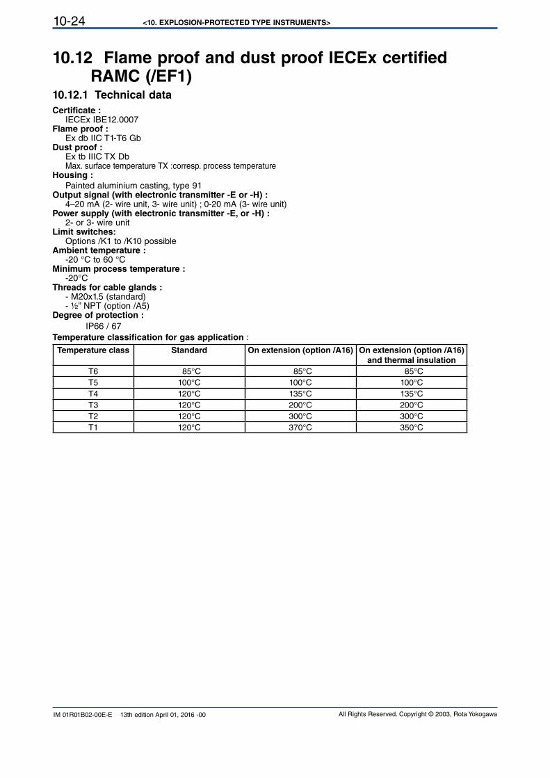
<10. EXPLOSION-PROTECTED TYPE INSTRUMENTS>10-24
All Rights Reserved. Copyright © 2003, Rota YokogawaIM 01R01B02-00E-E 13th edition April 01, 2016 -00
10.12 Flame proof and dust proof IECEx certified RAMC (/EF1)
10.12.1 Technical data
Certificate : IECEx IBE12.0007Flame proof : Ex db IIC T1-T6 Gb Dust proof : Ex tb IIIC TX Db Max. surface temperature TX :corresp. process temperature Housing :
Painted aluminium casting, type 91Output signal (with electronic transmitter -E or -H) : 4–20 mA (2- wire unit, 3- wire unit) ; 0-20 mA (3- wire unit)Power supply (with electronic transmitter -E, or -H) : 2- or 3- wire unitLimit switches: Options /K1 to /K10 possibleAmbient temperature : -20 °C to 60 °CMinimum process temperature : -20°CThreads for cable glands : - M20x1.5 (standard) - ½” NPT (option /A5)Degree of protection :
IP66 / 67Temperature classification for gas application :
Temperature class Standard On extension (option /A16) On extension (option /A16)
and thermal insulation
T6 85°C 85°C 85°CT5 100°C 100°C 100°CT4 120°C 135°C 135°CT3 120°C 200°C 200°CT2 120°C 300°C 300°CT1 120°C 370°C 350°C
<10. EXPLOSION-PROTECTED TYPE INSTRUMENTS> 10-25
All Rights Reserved. Copyright © 2003, Rota Yokogawa IM 01R01B02-00E-E 13th edition April 01, 2016 -00
10.12.2 Installation
For use in category 2G or 3G the electrical connections to the electronic transmitter and to the limit switches must be made via suitable cable glands and / or conduit systems that satisfy the requirements of IEC 60079-1 and for
which a separate test certificate is available. The cables, cable glands and stopping plugs must be specified for an ambient temperature of 100°C. Cable glands and entry fittings (screwed conduit entries) as well as stopping plugs of simple design may not be used. On connection of the RAMC /EF1 using a conduit entry approved for the purpose, the associated sealing facility must be arranged directly on the housing.
For use in category 2D or 3D the electrical connections to the electronic transmitter and to the limit switches must be made via suitable cable glands certified to the concerning dust category.
Unused openings shall be closed with certified stopping plugs in type of protection flame proof enclosure "d" (100°C) or dust proof depending on the existing category.Secure cable glands, stopping plugs and the safety screw for the cover against twisting.
The RAMC with option /EF1 shall be connected to the local equipollently grounding system. Therefore a grounding screw is available outside on the indicator housing and inside the indicator .
The electronic transmitter and the limit switches shall be wired as described in chapter 3.2.
10.12.3 Operation
If the cover of the indicator unit has to be opened, following instructions must be followed.
1. Switch off the power supply. 2. Wait 15 minutes after power is turned off before opening the covers. 3. The cover is fixed with a special screw. 4. Be sure to lock the cover with special screw after tightening the cover.
5. Before starting the operation again, be sure to lock the cover with the locking screw. 6. Users are prohibited from making any modifications of specifications or physical configuration, such as adding or changing the configuration of external wiring ports.
The instrument modification or parts replacement by other than authorized representatives of YOKOGAWA is prohibited and will void the certification.
If the window of the cover is damaged the RAMC must be set out of operation..
CAUTION
WARNING
CAUTION
WARNING
<10. EXPLOSION-PROTECTED TYPE INSTRUMENTS>10-26
All Rights Reserved. Copyright © 2003, Rota YokogawaIM 01R01B02-00E-E 13th edition April 01, 2016 -00
10.13 Intrinsically safe ATEX certified components in dust proof RAMC-housing (/KS2)
Certificate :
PTB 12 ATEX 2003 (Intrinsically safe electronic transmitter) PTB 99 ATEX 2219X (Intrinsically safe limit switches) (Pepperl&Fuchs) PTB 00 ATEX 2049X (Intrinsically safe fail safe limit switches) (Pepperl&Fuchs) IBExU 05 ATEX 1086 (Dust proof RAMC) Intrinsic safety :
Group II ; category 2G See chapter 10.1Dust proof :
Group II ; category 2D See chapter 10.10
CAUTION
RAMC with /A5 (threads for cable gland 1/2´´NPT) are delivered without cable glands. Please install suitable
cable glands or blind stopper according to the dust category where the flowmeter is installed.
10.14 Intrinsically safe IECEx certified components in dust proof RAMC- housing (/ES2)
Certificate :
IECEx PTB12.0020 (Intrinsically safe electronic transmitter)
IECEx PTB11.0091X (Intrinsically safe limit switches) (Pepperl&Fuchs) IECEx PTB11.0092X (Intrinsically safe fail safe limit switches) (Pepperl&Fuchs) IECEx IBE12.0007 (Dust proof RAMC)
Intrinsic safety :
Group II ; category 2G See chapter 10.6Dust proof :
Group II ; category 2D See chapter 10.10
CAUTION
RAMC with /A5 (threads for cable gland 1/2´´NPT) are delivered without cable glands. Please install suitable
cable glands or blind stopper according to the dust category where the flowmeter is installed.
<10. EXPLOSION-PROTECTED TYPE INSTRUMENTS> 10-27
All Rights Reserved. Copyright © 2003, Rota Yokogawa IM 01R01B02-00E-E 13th edition April 01, 2016 -00
10.15 Flame proof and dust proof NEPSI (China) certi-fied RAMC (/NF1)
10.15.1 Technical data
Certificate : GYJ071430Flame proof : Ex d IIC T6 Dust proof : DIP A20 TA T1 - T6 IP67 Max. surface temperature TA: corresponding process temperature Housing : Painted aluminium casting type 91Output signal (with electronic transmitter -E or -H) : 4–20 mA (2- wire unit, 3- wire unit) ; 0-20 mA (3- wire unit)Power supply (with electronic transmitter -E or -H) : 2- or 3- wire unitLimit switches : Options /K1 to /K10 possibleAmbient temperature : -20 °C to 60 °C -20 °C to 55 °C (for use in zone 20)Minimum process temperature : -20°CThreads for cable glands : - M16x1.5 (standard) - ½” NPT (option /A5)Temperature classification for gas application :
see chapter 10.10
10.15.2 Installation
For use in category 2G or 3G the electrical connections to the electronic transmitter and to the limit switches must be made via suitable cable glands and / or conduit systems that satisfy the requirements of IEC 60079-1 and for
which a separate test certificate is available. The cables, cable glands and stopping plugs must be specified for an ambient temperature of 100°C. Cable glands and entry fittings (screwed conduit entries) as well as stopping plugs of simple design may not be used. On connection of the RAMC /NF1 using a conduit entry approved for the purpose, the associated sealing facility must be arranged directly on the housing.
For use in category 2D or 3D the electrical connections to the electronic transmitter and to the limit switches
must be made via suitable cable glands certified to the concerning dust category.
Unused openings shall be closed with certified stopping plugs in type of protection flame proof enclosure "d" (100°C) or dust proof depending on the existing category.Secure cable glands, stopping plugs and the safety screw for the cover against twisting.
CAUTION
The RAMC with option /NF1 shall be connected to the local equipollently grounding system. Therefore a grounding screw is available outside on the indicator housing and inside the indicator .
The electronic transmitter and the limit switches shall be wired as described in chapter 3.2.
<10. EXPLOSION-PROTECTED TYPE INSTRUMENTS>10-28
All Rights Reserved. Copyright © 2003, Rota YokogawaIM 01R01B02-00E-E 13th edition April 01, 2016 -00
10.15.3 Operation
If the cover of the indicator unit has to be opened, following instructions must be followed.
CAUTION
1. Switch off the power supply. 2. Wait 15 minutes after power is turned off before opening the covers. 3. The cover is fixed with a special screw. 4. Be sure to lock the cover with special screw after tightening the cover.
5. Before starting the operation again, be sure to lock the cover with the locking screw. 6. Users are prohibited from making any modifications of specifications or physical configuration, such as adding or changing the configuration of external wiring ports.
WARNING
The instrument modification or parts replacement by other than authorized representatives of YOKOGAWA is prohibited and will void the certification.
WARNING
If the window of the cover is damaged the RAMC must be set out of operation.
10.16 Flame proof EAC (Russia, Belarus, Kazakhstan) certified RAMC (/GF1)
10.16.1 Technical data
Certificate: RU С-DЕ.ГБО8.В.00317Explosion proof:
1Ex d IIC T1...T6Housing: Painted aluminium casting type 91Output signal (with electronic transmitter -E or -H) : 4–20 mA (2- wire unit, 3- wire unit) ; 0-20 mA (3- wire unit)Power supply (with electronic transmitter -E or -H): 2- or 3- wire unitLimit switches: Options /K1 to /K10 possibleAmbient temperature: -20 °C to 60 °CMinimum process temperature: -20°CThreads for cable glands: - M16x1.5 (standard) - ½” NPT (option /A5)Temperature classification for gas application: see chapter 10.10
10.16.2 Installation
see 10.10.2
10.16.3 Operation
see 10.10.3
<10. EXPLOSION-PROTECTED TYPE INSTRUMENTS> 10-29
All Rights Reserved. Copyright © 2003, Rota Yokogawa IM 01R01B02-00E-E 13th edition April 01, 2016 -00
10.17 ATEX registrated non-electrical RAMC (/KC1)
10.17.1 Technical data
Applicable Standards: EN 13463-1: 2009Archive No.: IBExU 099/15Explosion proof:
II 2GD IIC TX TX = max. surface temperature determined by the process temperatureAmbient temperature: -25 °C to +90 °C -40 °C to +90 °C with option /A26Process temperature: see chapter 9.5Heat tracing: same as process temperature
NOTE
The maximum surface temperature depends on the process temperature and for meters with option /T1 to /T6 additional on the heat tracing temperature.
Protection: IP66/67
10.17.2 Safety Instructions
Identified hazards:- flammable products inside tube- static electricity
WARNING
Operation with flammable products is only permitted as long as no explosive mixture builds up on the inside of the flowmeter under operating conditions. The operator is responsible for ensuring that the flowmeter is operated safely as regards the temperature and pressure of the products used. In case of operation with flammable products the measuring units must be included in the periodic pressure tests of the system.
If conductive fluids are used with stainless steel as material of wetted parts the Rotameter must be connected to the potential equalization.
If conductive fluids are used with Teflon as material of wetted parts use a medium with minimum conductivity of 1nS/m.
CAUTION
1. Supply grounding connection by the process connections or earthing terminal.2. In hazardous areas, only operate the indicator with a closed cover. 3. Ignition risks caused by process pressure surges, impact or friction must be avoided. 4. Use of the equipment is not permitted in areas where the following occur: processes that generate strong charges, machine grinding and separation processes, electronic spraying (e.g. near electrostatic painting systems) or pneumatically conveyed dust.
10.17.3 Marking
Archive no. IBExU 99/15 II 2GD IIC TX T
amb. -25 °C to +90 °C
<10. EXPLOSION-PROTECTED TYPE INSTRUMENTS>10-30
All Rights Reserved. Copyright © 2003, Rota YokogawaIM 01R01B02-00E-E 13th edition April 01, 2016 -00
10.18 EAC certified non-electrical RAMC (/GC1)
10.18.1 Technical data
Applicable Standards: EN 13463-1: 2009Certificate number: RU С-DЕ.ГБО8.В.001183 Explosion proof: II 2GD IIC TX TX = max. surface temperature determined by the process temperatureAmbient temperature: -25 °C to +90 °C -40 °C to +90 °C with option /A26Process temperature: see chapter 9.5Heat tracing: same as process temperature
NOTE
The maximum surface temperature depends on the process temperature and for meters with option /T1 to /T6 additional on the heat tracing temperature.
Protection: IP66/67
10.18.2 Safety Instructions
Identified hazards:- flammable products inside tube- static electricity
WARNING
Operation with flammable products is only permitted as long as no explosive mixture builds up on the inside of the flowmeter under operating condition. The operator is responsible for ensure that the flowmeter is operated safely as regards the temperature and pressure of the products used. In case of operation with flammable products the measuring units must be included in the periodic pressure tests of the system.
If conductive fluids are used with stainless steel as material of wetted parts the Rotameter must be connected to the potential equalization.
If conductive fluids are used with Teflon as material of wetted parts use a medium with minimum conductivity of 1nS/m.
CAUTION
1. Supply grounding connection by the process connections or earthing terminal.2. In hazardous areas, only operate the indicator with a closed cover. 3. Ignition risks caused by process pressure surges, impact or friction must be avoided. 4. Use of the equipment is not permitted in areas where the following occur: processes that generate strong charges, machine grinding and separation processes, electron spraying (e.g. near electrostatic painting systems) or pneumatically conveyed dust.
10.18.3 Marking
Certificate No. RU С-DЕ.ГБО8.В.01183IIC TXT
amb. -40 °C to +90 °C
<10. EXPLOSION-PROTECTED TYPE INSTRUMENTS> 10-31
All Rights Reserved. Copyright © 2003, Rota Yokogawa IM 01R01B02-00E-E 13th edition April 01, 2016 -00
10.19 Flame proof and dust proof RAMC with Taiwan Safety Label
Registration Document: ML041200702782Option /EF1 must be selected.Same data as IECEx-certifiied type (/EF1)For export to Taiwan please contact your Yokogawa representative regarding Taiwan Safety Label
10.20 Flame proof and dust proof PESO (India) certified RAMC
Identification No.: P209233/1Option /KF1 must be selected.Same data as ATEX-certifiied type (/KF1)Please contact your Yokogawa representative regarding Peso certificate.
<10. EXPLOSION-PROTECTED TYPE INSTRUMENTS>10-32
All Rights Reserved. Copyright © 2003, Rota YokogawaIM 01R01B02-00E-E 13th edition April 01, 2016 -00
Blank Page
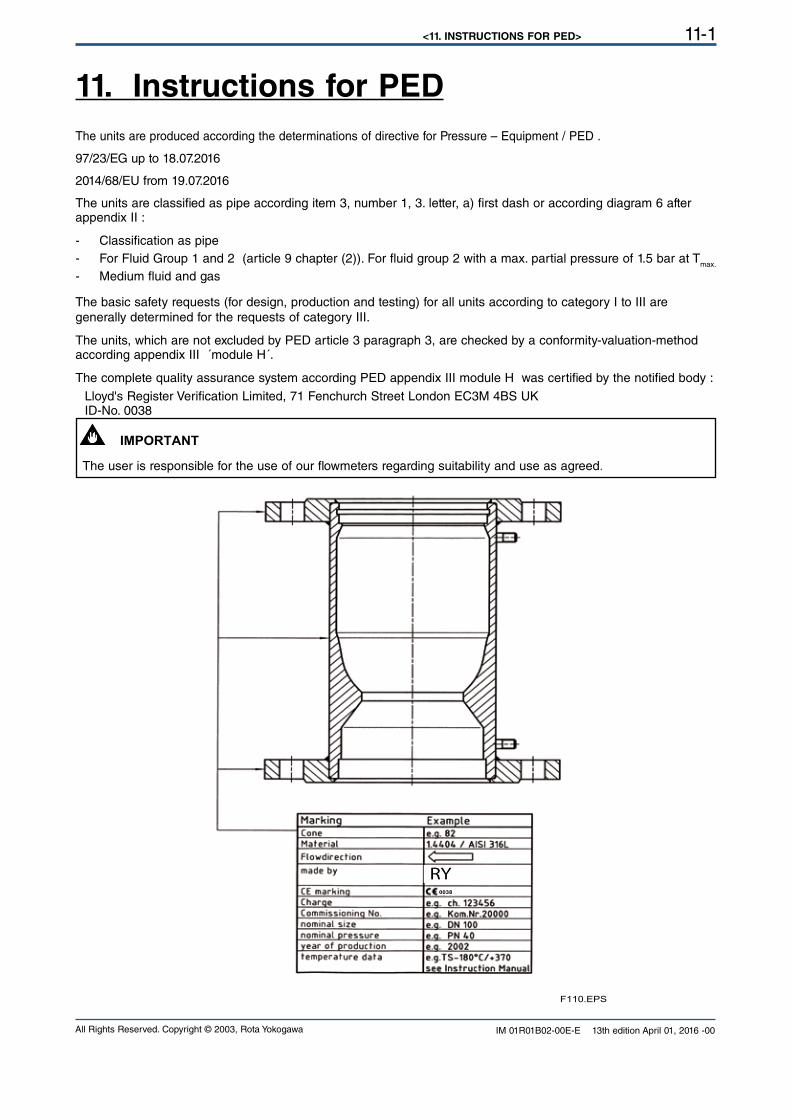
<11. INSTRUCTIONS FOR PED> 11-1
All Rights Reserved. Copyright © 2003, Rota Yokogawa IM 01R01B02-00E-E 13th edition April 01, 2016 -00
The units are produced according the determinations of directive for Pressure – Equipment / PED .
97/23/EG up to 18.07.2016
2014/68/EU from 19.07.2016
The units are classified as pipe according item 3, number 1, 3. letter, a) first dash or according diagram 6 after appendix II :
- Classification as pipe
- For Fluid Group 1 and 2 (article 9 chapter (2)). For fluid group 2 with a max. partial pressure of 1.5 bar at Tmax.
- Medium fluid and gas
The basic safety requests (for design, production and testing) for all units according to category I to III are generally determined for the requests of category III.
The units, which are not excluded by PED article 3 paragraph 3, are checked by a conformity-valuation-method according appendix III ´module H´.
The complete quality assurance system according PED appendix III module H was certified by the notified body :
Lloyd's Register Verification Limited, 71 Fenchurch Street London EC3M 4BS UKID-No. 0038
The user is responsible for the use of our flowmeters regarding suitability and use as agreed.
PED-Data on RAMC
11. Instructions for PED
F110.EPS
0038
RY
IMPORTANT
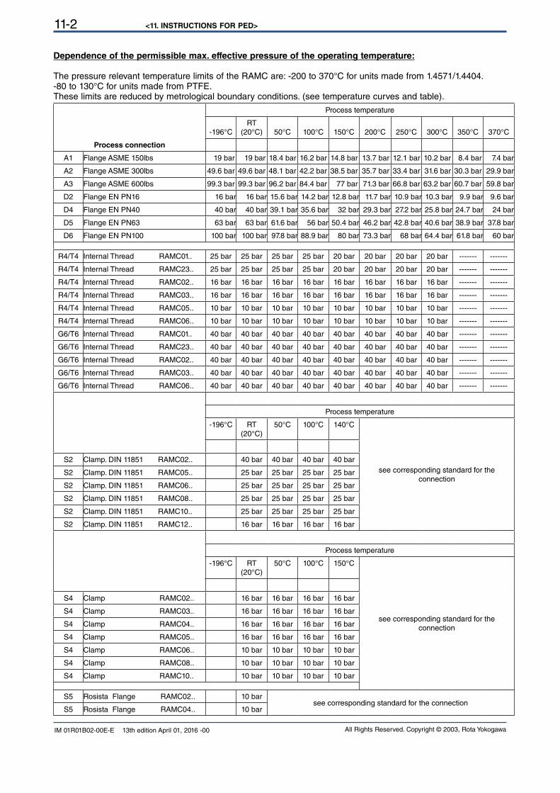
<11. INSTRUCTIONS FOR PED>11-2
All Rights Reserved. Copyright © 2003, Rota YokogawaIM 01R01B02-00E-E 13th edition April 01, 2016 -00
Dependence of the permissible max. effective pressure of the operating temperature:
The pressure relevant temperature limits of the RAMC are: -200 to 370°C for units made from 1.4571/1.4404.-80 to 130°C for units made from PTFE.These limits are reduced by metrological boundary conditions. (see temperature curves and table).
Process connection
Process temperature
-196°CRT
(20°C) 50°C 100°C 150°C 200°C 250°C 300°C 350°C 370°C
A1 Flange ASME 150lbs 19 bar 19 bar 18.4 bar 16.2 bar 14.8 bar 13.7 bar 12.1 bar 10.2 bar 8.4 bar 7.4 bar
A2 Flange ASME 300lbs 49.6 bar 49.6 bar 48.1 bar 42.2 bar 38.5 bar 35.7 bar 33.4 bar 31.6 bar 30.3 bar 29.9 bar
A3 Flange ASME 600lbs 99.3 bar 99.3 bar 96.2 bar 84.4 bar 77 bar 71.3 bar 66.8 bar 63.2 bar 60.7 bar 59.8 bar
D2 Flange EN PN16 16 bar 16 bar 15.6 bar 14.2 bar 12.8 bar 11.7 bar 10.9 bar 10.3 bar 9.9 bar 9.6 bar
D4 Flange EN PN40 40 bar 40 bar 39.1 bar 35.6 bar 32 bar 29.3 bar 27.2 bar 25.8 bar 24.7 bar 24 bar
D5 Flange EN PN63 63 bar 63 bar 61.6 bar 56 bar 50.4 bar 46.2 bar 42.8 bar 40.6 bar 38.9 bar 37.8 bar
D6 Flange EN PN100 100 bar 100 bar 97.8 bar 88.9 bar 80 bar 73.3 bar 68 bar 64.4 bar 61.8 bar 60 bar
R4/T4 Internal Thread RAMC01.. 25 bar 25 bar 25 bar 25 bar 20 bar 20 bar 20 bar 20 bar ------- -------
R4/T4 Internal Thread RAMC23.. 25 bar 25 bar 25 bar 25 bar 20 bar 20 bar 20 bar 20 bar ------- -------
R4/T4 Internal Thread RAMC02.. 16 bar 16 bar 16 bar 16 bar 16 bar 16 bar 16 bar 16 bar ------- -------
R4/T4 Internal Thread RAMC03.. 16 bar 16 bar 16 bar 16 bar 16 bar 16 bar 16 bar 16 bar ------- -------
R4/T4 Internal Thread RAMC05.. 10 bar 10 bar 10 bar 10 bar 10 bar 10 bar 10 bar 10 bar ------- -------
R4/T4 Internal Thread RAMC06.. 10 bar 10 bar 10 bar 10 bar 10 bar 10 bar 10 bar 10 bar ------- -------
G6/T6 Internal Thread RAMC01.. 40 bar 40 bar 40 bar 40 bar 40 bar 40 bar 40 bar 40 bar ------- -------
G6/T6 Internal Thread RAMC23.. 40 bar 40 bar 40 bar 40 bar 40 bar 40 bar 40 bar 40 bar ------- -------
G6/T6 Internal Thread RAMC02.. 40 bar 40 bar 40 bar 40 bar 40 bar 40 bar 40 bar 40 bar ------- -------
G6/T6 Internal Thread RAMC03.. 40 bar 40 bar 40 bar 40 bar 40 bar 40 bar 40 bar 40 bar ------- -------
G6/T6 Internal Thread RAMC06.. 40 bar 40 bar 40 bar 40 bar 40 bar 40 bar 40 bar 40 bar ------- -------
Process temperature
-196°C RT (20°C)
50°C 100°C 140°C
see corresponding standard for the
connection
S2 Clamp. DIN 11851 RAMC02.. 40 bar 40 bar 40 bar 40 bar
S2 Clamp. DIN 11851 RAMC05.. 25 bar 25 bar 25 bar 25 bar
S2 Clamp. DIN 11851 RAMC06.. 25 bar 25 bar 25 bar 25 bar
S2 Clamp. DIN 11851 RAMC08.. 25 bar 25 bar 25 bar 25 bar
S2 Clamp. DIN 11851 RAMC10.. 25 bar 25 bar 25 bar 25 bar
S2 Clamp. DIN 11851 RAMC12.. 16 bar 16 bar 16 bar 16 bar
Process temperature
-196°C RT (20°C)
50°C 100°C 150°C
see corresponding standard for the
connection
S4 Clamp RAMC02.. 16 bar 16 bar 16 bar 16 bar
S4 Clamp RAMC03.. 16 bar 16 bar 16 bar 16 bar
S4 Clamp RAMC04.. 16 bar 16 bar 16 bar 16 bar
S4 Clamp RAMC05.. 16 bar 16 bar 16 bar 16 bar
S4 Clamp RAMC06.. 10 bar 10 bar 10 bar 10 bar
S4 Clamp RAMC08.. 10 bar 10 bar 10 bar 10 bar
S4 Clamp RAMC10.. 10 bar 10 bar 10 bar 10 bar
S5 Rosista Flange RAMC02.. 10 barsee corresponding standard for the connection
S5 Rosista Flange RAMC04.. 10 bar
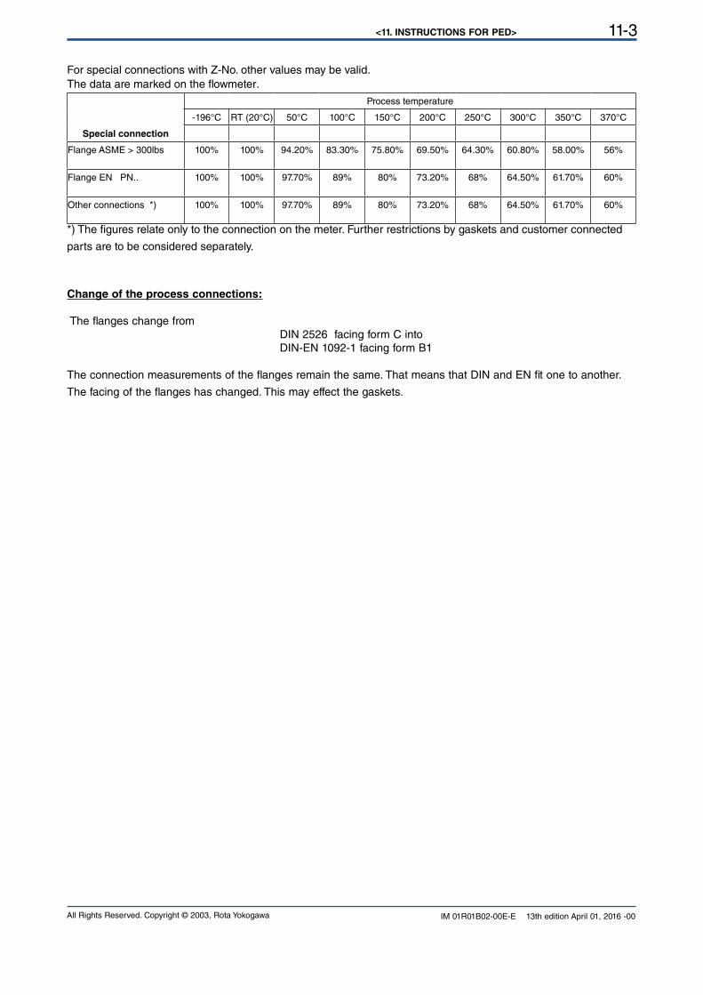
<11. INSTRUCTIONS FOR PED> 11-3
All Rights Reserved. Copyright © 2003, Rota Yokogawa IM 01R01B02-00E-E 13th edition April 01, 2016 -00
For special connections with Z-No. other values may be valid.The data are marked on the flowmeter.
Special connection
Process temperature
-196°C RT (20°C) 50°C 100°C 150°C 200°C 250°C 300°C 350°C 370°C
Flange ASME > 300lbs 100% 100% 94.20% 83.30% 75.80% 69.50% 64.30% 60.80% 58.00% 56%
Flange EN PN.. 100% 100% 97.70% 89% 80% 73.20% 68% 64.50% 61.70% 60%
Other connections *) 100% 100% 97.70% 89% 80% 73.20% 68% 64.50% 61.70% 60%
*) The figures relate only to the connection on the meter. Further restrictions by gaskets and customer connected
parts are to be considered separately.
Change of the process connections:
The flanges change from DIN 2526 facing form C into DIN-EN 1092-1 facing form B1
The connection measurements of the flanges remain the same. That means that DIN and EN fit one to another.
The facing of the flanges has changed. This may effect the gaskets.
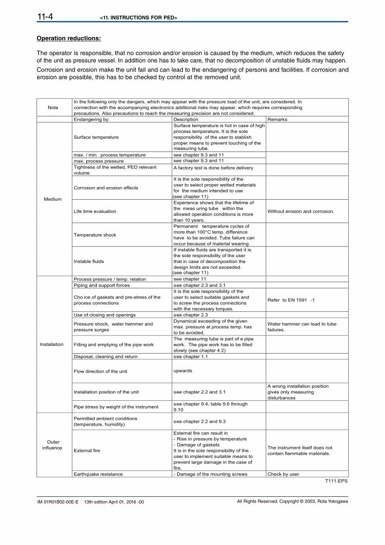
<11. INSTRUCTIONS FOR PED>11-4
All Rights Reserved. Copyright © 2003, Rota YokogawaIM 01R01B02-00E-E 13th edition April 01, 2016 -00
Operation reductions:
The operator is responsible, that no corrosion and/or erosion is caused by the medium, which reduces the safety of the unit as pressure vessel. In addition one has to take care, that no decomposition of unstable fluids may happen.
Corrosion and erosion make the unit fail and can lead to the endangering of persons and facilities. If corrosion and
erosion are possible, this has to be checked by control at the removed unit.
Note
In the following only the dangers, which may appear with the pressure load of the unit, are considered. In
connection with the accompanying electronics additional risks may appear, which requires corresponding
precautions. Also precautions to reach the measuring precision are not considered.
Endangering by: Description Remarks
Surface temperature
Surface temperature is hot in case of high
process temperature. It is the sole
responsibility of the user to stablish
proper means to prevent touching of the
measuring tube.
max. / min. process temperature see chapter 9.3 and 11
max. process pressure
Tightness of the wetted, PED relevant
volume A factory test is done before delivery
Corrosion and erosion effects
It is the sole responsibility of the
user to select proper wetted materials
for the medium intended to use
(see chapter 11)
Life time evaluation
Experience shows that the lifetime of
the meas uring tube within the
allowed operation conditions is more
than 10 years.
Without erosion and corrosion.
Temperature shock
Permanent temperature cycles of
more than 100°C temp. difference
have to be avoided. Tube failure can
occur because of material wearing.
Medium
Instable fluids
If instable fluids are transported it is
the sole responsibility of the user
that in case of decomposition the
design limits are not exceeded.
Process pressure / temp. relation
Piping and support forces see chapter 2.3 and 3.1
Cho ice of gaskets and pre-stress of the
process connections
It is the sole responsibility of the
user to select suitable gaskets and
to screw the process connections
with the necessary torques.
Refer to EN 1591 -1
Use of closing and openings see chapter 2.3
Pressure shock, water hammer and
pressure surges
Dynamical exceeding of the given
max. pressure at process temp. has
to be avoided.
Water hammer can lead to tube
failures.
Filling and emptying of the pipe work
The measuring tube is part of a pipe
work. The pipe work has to be filled
slowly (see chapter 4.2)
Disposal, cleaning and return see chapter 1.1
Flow direction of the unit upwards
Installation position of the unit see chapter 2.2 and 3.1
A wrong installation position
gives only measuring
disturbances
Installation
Pipe stress by weight of the instrument see chapter 9.4, table 9.6 through
9.10
Permitted ambient conditions
(temperature, humidity) see chapter 2.2 and 9.3
External fire
External fire can result in
- Rise in pressure by temperature
- Damage of gaskets
It is in the sole responsibility of the
user to implement suitable means to
prevent large damage in the case of
fire.
The instrument itself does not
contain flammable materials.
Outer
influence
Earthquake resistance - Damage of the mounting screws Check by user
see chapter 9.3 and 11
(see chapter 11)
see chapter 11
T111.EPS
<11. INSTRUCTIONS FOR PED> 11-5
All Rights Reserved. Copyright © 2003, Rota Yokogawa IM 01R01B02-00E-E 13th edition April 01, 2016 -00
The following usages of the instruments are not permitted:- use as climbing aid (e.g during assembling work on pipe system)
- use as support for external load (e.g. support for piping) or tray surface for heavy tools (e.g. during piping work)
- Material removal by any kind of machining (e.g. drilling, sawing etc.)
- Painting of the name-plate/scale- Brazing or welding of parts to the instrument
- Any repair, modification or supplements or the installation of spare-parts is only permitted if it is done in
accordance to this instruction manual. Other work must be agreed by YOKOGAWA beforehand.
YOKOGAWA will not take over any liability for damages caused by unauthorized work on the instrument
or prohibited usage of the instrument.
<11. INSTRUCTIONS FOR PED>11-6
All Rights Reserved. Copyright © 2003, Rota YokogawaIM 01R01B02-00E-E 13th edition April 01, 2016 -00
Blank Page
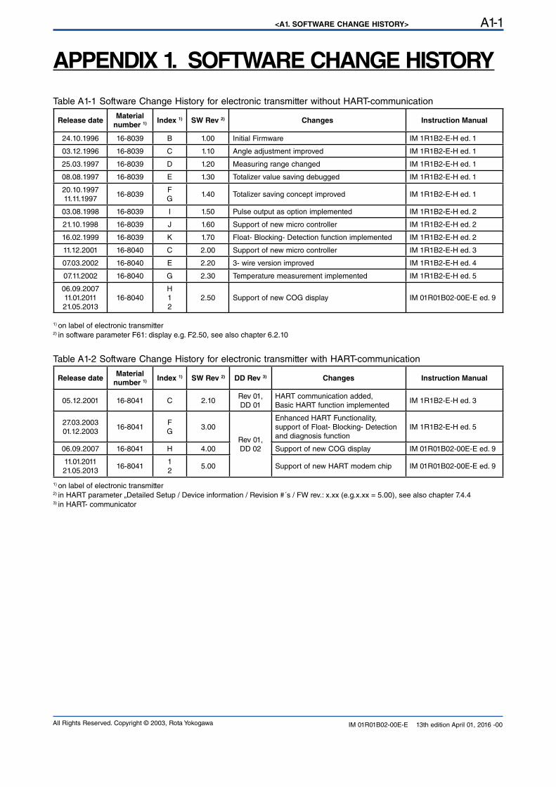
<A1. SOFTWARE CHANGE HISTORY> A1-1
All Rights Reserved. Copyright © 2003, Rota Yokogawa IM 01R01B02-00E-E 13th edition April 01, 2016 -00
APPENDIX 1. SOFTWARE CHANGE HISTORY
Table A1-1 Software Change History for electronic transmitter without HART-communication
Release dateMaterial
number 1) Index 1) SW Rev 2) Changes Instruction Manual
24.10.1996 16-8039 B 1.00 Initial Firmware IM 1R1B2-E-H ed. 1
03.12.1996 16-8039 C 1.10 Angle adjustment improved IM 1R1B2-E-H ed. 1
25.03.1997 16-8039 D 1.20 Measuring range changed IM 1R1B2-E-H ed. 1
08.08.1997 16-8039 E 1.30 Totalizer value saving debugged IM 1R1B2-E-H ed. 1
20.10.1997
11.11.199716-8039
FG
1.40 Totalizer saving concept improved IM 1R1B2-E-H ed. 1
03.08.1998 16-8039 I 1.50 Pulse output as option implemented IM 1R1B2-E-H ed. 2
21.10.1998 16-8039 J 1.60 Support of new micro controller IM 1R1B2-E-H ed. 2
16.02.1999 16-8039 K 1.70 Float- Blocking- Detection function implemented IM 1R1B2-E-H ed. 2
11.12.2001 16-8040 C 2.00 Support of new micro controller IM 1R1B2-E-H ed. 3
07.03.2002 16-8040 E 2.20 3- wire version improved IM 1R1B2-E-H ed. 4
07.11.2002 16-8040 G 2.30 Temperature measurement implemented IM 1R1B2-E-H ed. 5
06.09.2007
11.01.2011
21.05.201316-8040
H
1
2
2.50 Support of new COG display IM 01R01B02-00E-E ed. 9
1) on label of electronic transmitter2) in software parameter F61: display e.g. F2.50, see also chapter 6.2.10
Table A1-2 Software Change History for electronic transmitter with HART-communication
Release dateMaterial
number 1) Index 1) SW Rev 2) DD Rev 3) Changes Instruction Manual
05.12.2001 16-8041 C 2.10Rev 01,
DD 01
HART communication added,Basic HART function implemented
IM 1R1B2-E-H ed. 3
27.03.2003
01.12.200316-8041
FG
3.00
Rev 01,
DD 02
Enhanced HART Functionality, support of Float- Blocking- Detection and diagnosis function
IM 1R1B2-E-H ed. 5
06.09.2007 16-8041 H 4.00 Support of new COG display IM 01R01B02-00E-E ed. 9
11.01.2011
21.05.201316-8041
1
25.00 Support of new HART modem chip IM 01R01B02-00E-E ed. 9
1) on label of electronic transmitter2) in HART parameter „Detailed Setup / Device information / Revision #´s / FW rev.: x.xx (e.g.x.xx = 5.00), see also chapter 7.4.43) in HART- communicator
<A1. SOFTWARE CHANGE HISTORY>A1-2
All Rights Reserved. Copyright © 2003, Rota YokogawaIM 01R01B02-00E-E 13th edition April 01, 2016 -00
Blank Page
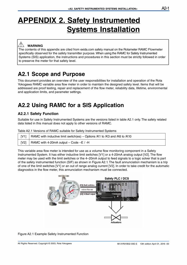
<A2. SAFETY INSTRUMENTED SYSTEMS INSTALLATION> A2-1
All Rights Reserved. Copyright © 2003, Rota Yokogawa IM 01R01B02-00E-E 13th edition April 01, 2016 -00
The contents of this appendix are cited from exida.com safety manual on the Rotameter RAMC Flowmeter specifically observed for the safety transmitter purpose. When using the RAMC for Safety Instrumented Systems (SIS) application, the instructions and procedures in this section must be strictly followed in order to preserve the meter for that safety level.
A2.1 Scope and PurposeThis document provides an overview of the user responsibilities for installation and operation of the Rota Yokogawa RAMC variable area flow meter in order to maintain the designed safety level. Items that will be addressed are proof testing, repair and replacement of the flow meter, reliability data, lifetime, environmental and application limits, and parameter settings.
A2.2 Using RAMC for a SIS Application
A2.2.1 Safety Function
Suitable for use in Safety Instrumented Systems are the versions listed in table A2.1 only. The safety related data listed in this manual does not apply to other versions of RAMC.
Table A2.1 Versions of RAMC suitable for Safety Instrumented Systems
[V1] RAMC with inductive limit switch(es) – Options /K1 to /K3 and /K6 to /K10
[V2] RAMC with 4-20mA output – Code –E / -H
This variable area flow meter is intended for use as a volume flow monitoring component in a Safety Instrumented System. It has either inductive limit switches [V1] or a 4-20mA analog output [V2]. The flow meter may be used with the limit switches or the 4–20mA output to feed signals to a logic solver that is part of the safety instrumented function (SIF) as shown in Figure A2.1. The fault annunciation mechanism is a trip of one of the limit switches [V1] or an out of range analog current [V2]. In order to take credit for the automatic diagnostics in the flow meter, this annunciation mechanism must be connected.
Figure A2.1 Example Safety Instrumented Function
APPENDIX 2. Safety Instrumented
Systems Installation
WARNING
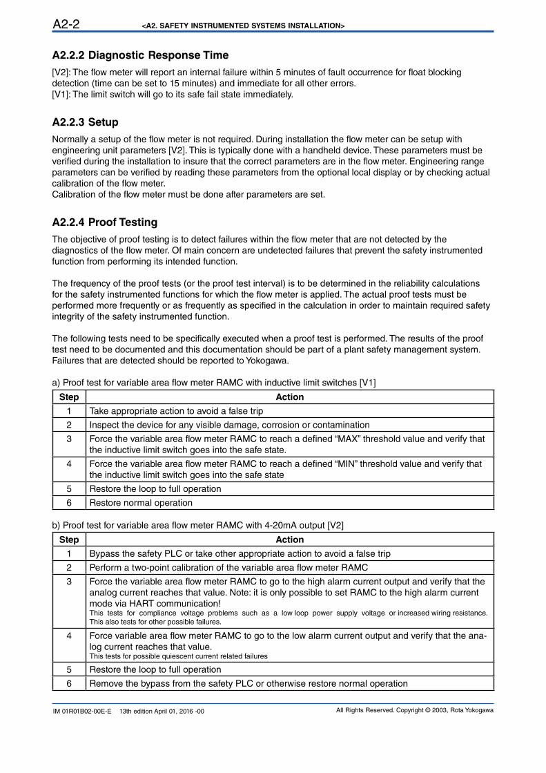
<A2. SAFETY INSTRUMENTED SYSTEMS INSTALLATION>A2-2
All Rights Reserved. Copyright © 2003, Rota YokogawaIM 01R01B02-00E-E 13th edition April 01, 2016 -00
A2.2.2 Diagnostic Response Time
[V2]: The flow meter will report an internal failure within 5 minutes of fault occurrence for float blocking detection (time can be set to 15 minutes) and immediate for all other errors.[V1]: The limit switch will go to its safe fail state immediately.
A2.2.3 Setup
Normally a setup of the flow meter is not required. During installation the flow meter can be setup with engineering unit parameters [V2]. This is typically done with a handheld device. These parameters must be verified during the installation to insure that the correct parameters are in the flow meter. Engineering range parameters can be verified by reading these parameters from the optional local display or by checking actual
calibration of the flow meter.Calibration of the flow meter must be done after parameters are set.
A2.2.4 Proof Testing
The objective of proof testing is to detect failures within the flow meter that are not detected by the diagnostics of the flow meter. Of main concern are undetected failures that prevent the safety instrumented function from performing its intended function.
The frequency of the proof tests (or the proof test interval) is to be determined in the reliability calculations for the safety instrumented functions for which the flow meter is applied. The actual proof tests must be performed more frequently or as frequently as specified in the calculation in order to maintain required safety
integrity of the safety instrumented function.
The following tests need to be specifically executed when a proof test is performed. The results of the proof test need to be documented and this documentation should be part of a plant safety management system.
Failures that are detected should be reported to Yokogawa.
a) Proof test for variable area flow meter RAMC with inductive limit switches [V1]
Step Action
1 Take appropriate action to avoid a false trip
2 Inspect the device for any visible damage, corrosion or contamination
3 Force the variable area flow meter RAMC to reach a defined “MAX” threshold value and verify that the inductive limit switch goes into the safe state.
4 Force the variable area flow meter RAMC to reach a defined “MIN” threshold value and verify that the inductive limit switch goes into the safe state
5 Restore the loop to full operation
6 Restore normal operation
b) Proof test for variable area flow meter RAMC with 4-20mA output [V2]
Step Action
1 Bypass the safety PLC or take other appropriate action to avoid a false trip
2 Perform a two-point calibration of the variable area flow meter RAMC
3 Force the variable area flow meter RAMC to go to the high alarm current output and verify that the analog current reaches that value. Note: it is only possible to set RAMC to the high alarm current mode via HART communication!This tests for compliance voltage problems such as a low loop power supply voltage or increased wiring resistance. This also tests for other possible failures.
4 Force variable area flow meter RAMC to go to the low alarm current output and verify that the ana-
log current reaches that value.This tests for possible quiescent current related failures
5 Restore the loop to full operation
6 Remove the bypass from the safety PLC or otherwise restore normal operation
<A2. SAFETY INSTRUMENTED SYSTEMS INSTALLATION> A2-3
All Rights Reserved. Copyright © 2003, Rota Yokogawa IM 01R01B02-00E-E 13th edition April 01, 2016 -00
When all the tests listed above are executed a proof test coverage of approximately 99% of possible DU failures in the variable area flow meter RAMC can be claimed.
The following tools need to be available to perform proof testing: • Flow meter display or alternatively for digital communication ([V2] only): HART Handheld, PRM or FieldMate • Measurement instrument to verify output status [V1] or output current [V2]
The person(s) performing the proof test of the Yokogawa RAMC variable area flow meter should be trained in SIS operations including bypass procedures, flow meter maintenance and company management of change procedures.
A2.2.5 Repair and replacement
Maintenance information can be found in section 8, Maintenance of the User’s Manual Model RAMC Short Stroke ROTAMETER, IM 01R01B02-00E-E.If repair is to be performed with the process online the Rota Yokogawa RAMC variable area flow meter will need to be bypassed during the repair. The user should setup appropriate bypass procedures for that.Contact the Yokogawa sales office if this instrument requires repair
The person(s) performing the repair and / or replacement of the Rota Yokogawa RAMC variable area flow meter should have a sufficient skill level.
A2.2.6 Startup Time
The flow meter will generate a valid signal within 3 seconds of power-on startup with the default 1 second dampening time. Increasing the configurable dampening time adds to the startup time.
A2.2.7 Firmware update
In case firmware updates are required they will be performed at factory. The replacement responsibilities are then in place. The user will not be required to perform any firmware updates.
A2.2.8 Reliability data
A detailed Failure Mode, Effects, and Diagnostics Analysis (FMEDA) report is available from Rota Yokogawa with all failure rates and failure modes. Rota Yokogawa RAMC variable area flow meter is intended for use in a Low Demand Mode. Low Demand Mode means the average interval between dangerous conditions occurs infrequently.
The Rota Yokogawa RAMC variable area flow meter is certified up to SIL2 for use in a simplex (1oo1) configuration, depending on the PFDAVG calculation of the entire Safety Instrumented Function.
A2.2.9 Lifetime limits
The expected lifetime of the Yokogawa Rota Yokogawa RAMC variable area flow meter is 10 years. The reliability data listed in A2.2.8 is only valid for this period. The failure rates of the Rota Yokogawa RAMC variable area flow meter may increase sometime after this period. Reliability calculations based on the data listed in A2. 2.8 for Rota Yokogawa RAMC variable area flow meter lifetimes beyond 10 years may yield results that are too optimistic, i.e. the calculated Safety Integrity Level will not be achieved.
A2.2.10 Required parameter settings
The Float Blocking Detection System must be activated for 4-20mA Type [V2].
<A2. SAFETY INSTRUMENTED SYSTEMS INSTALLATION>A2-4
All Rights Reserved. Copyright © 2003, Rota YokogawaIM 01R01B02-00E-E 13th edition April 01, 2016 -00
A2.2.11 Environmental limits
The environmental limits of Rota Yokogawa RAMC variable area flow meter are specified in the User’s Manual, Model RAMC Short Stroke ROTAMETER IM 01R01B02-00E-E.
A2.2.12 Application limits
The application limits of the Rota Yokogawa RAMC variable area flow meter are specified in the User’s Manual, Model RAMC Short Stroke ROTAMETER,IM 01R01B02-00E-E. If the flow meter is used outside of the application limits the reliability data listed in A2.2.9 becomes invalid.
A2.3 Definitions and Abbreviations
A2.3.1 Definitions
Safety Freedom from unacceptable risk of harm
Functional Safety The ability of a system to carry out the actions necessary to achieve or to maintain a defined safe state for the equipment / machinery / plant / apparatus
under control of the system
Basic Safety The equipment must be designed and manufactured such that it protects against risk of damage to persons by electrical shock and other hazards
and against resulting fire and explosion. The protection must be effective under all conditions of the nominal operation and under single fault condition
Verification The demonstration for each phase of the life-cycle that the (output) deliverables of the phase meet the objectives and requirements specified by the inputs to the phase. The verification is usually executed by analysis and / or testing:
Validation The demonstration that the safety-related system(s) or the combination of safety-related system(s) and external risk reduction facilities meet, in all respects, the Safety Requirements Specification. The validation is usually executed by testing
Safety Assessment The investigation to arrive at a judgment - based on evidence - of the safety achieved by safety-related systems
Further definitions of terms used for safety techniques and measures and the description of safety related systems are given in IEC 61508-4.
A2.3.2 Abbreviations
FMEDA Failure Mode, Effects and Diagnostic Analysis
SIF Safety Instrumented Function
SIL Safety Integrity Level
SIS Safety Instrumented System
SLC Safety Lifecycle
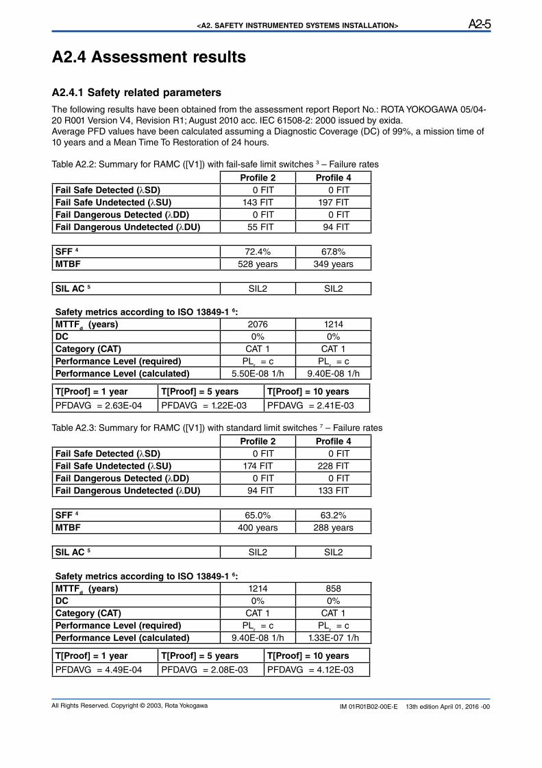
<A2. SAFETY INSTRUMENTED SYSTEMS INSTALLATION> A2-5
All Rights Reserved. Copyright © 2003, Rota Yokogawa IM 01R01B02-00E-E 13th edition April 01, 2016 -00
A2.4 Assessment results
A2.4.1 Safety related parameters
The following results have been obtained from the assessment report Report No.: ROTA YOKOGAWA 05/04-20 R001 Version V4, Revision R1; August 2010 acc. IEC 61508-2: 2000 issued by exida.Average PFD values have been calculated assuming a Diagnostic Coverage (DC) of 99%, a mission time of 10 years and a Mean Time To Restoration of 24 hours.
Table A2.2: Summary for RAMC ([V1]) with fail-safe limit switches 3 – Failure rates
Profile 2 Profile 4
Fail Safe Detected (λSD) 0 FIT 0 FITFail Safe Undetected (λSU) 143 FIT 197 FITFail Dangerous Detected (λDD) 0 FIT 0 FITFail Dangerous Undetected (λDU) 55 FIT 94 FIT
SFF 4 72.4% 67.8%MTBF 528 years 349 years
SIL AC 5 SIL2 SIL2
Safety metrics according to ISO 13849-1 6:
MTTFd (years) 2076 1214
DC 0% 0%Category (CAT) CAT 1 CAT 1Performance Level (required) PL
r = c PL
r = c
Performance Level (calculated) 5.50E-08 1/h 9.40E-08 1/h
T[Proof] = 1 year T[Proof] = 5 years T[Proof] = 10 years
PFDAVG = 2.63E-04 PFDAVG = 1.22E-03 PFDAVG = 2.41E-03
Table A2.3: Summary for RAMC ([V1]) with standard limit switches 7 – Failure rates
Profile 2 Profile 4
Fail Safe Detected (λSD) 0 FIT 0 FITFail Safe Undetected (λSU) 174 FIT 228 FITFail Dangerous Detected (λDD) 0 FIT 0 FITFail Dangerous Undetected (λDU) 94 FIT 133 FIT
SFF 4 65.0% 63.2%MTBF 400 years 288 years
SIL AC 5 SIL2 SIL2
Safety metrics according to ISO 13849-1 6:
MTTFd (years) 1214 858
DC 0% 0%Category (CAT) CAT 1 CAT 1Performance Level (required) PL
r = c PL
r = c
Performance Level (calculated) 9.40E-08 1/h 1.33E-07 1/h
T[Proof] = 1 year T[Proof] = 5 years T[Proof] = 10 years
PFDAVG = 4.49E-04 PFDAVG = 2.08E-03 PFDAVG = 4.12E-03
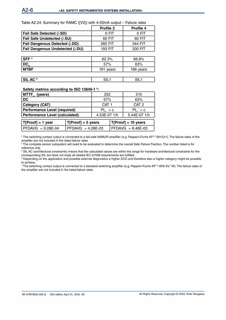
<A2. SAFETY INSTRUMENTED SYSTEMS INSTALLATION>A2-6
All Rights Reserved. Copyright © 2003, Rota YokogawaIM 01R01B02-00E-E 13th edition April 01, 2016 -00
Table A2.24: Summary for RAMC ([V2]) with 4-20mA output – Failure rates
Profile 2 Profile 4
Fail Safe Detected (λSD) 0 FIT 0 FITFail Safe Undetected (λSU) 60 FIT 60 FITFail Dangerous Detected (λDD) 260 FIT 344 FITFail Dangerous Undetected (λDU) 193 FIT 200 FIT
SFF 4 62.3% 66.8%DC
D57% 63%
MTBF 191 years 166 years
SIL AC 5 SIL1 SIL1
Safety metrics according to ISO 13849-1 6:
MTTFd (years) 252 210
DC 57% 63%Category (CAT) CAT 1 CAT 2Performance Level (required) PL
r = c PL
r = c
Performance Level (calculated) 4.53E-07 1/h 5.44E-07 1/h
T[Proof] = 1 year T[Proof] = 5 years T[Proof] = 10 years
PFDAVG = 9.28E-04 PFDAVG = 4.28E-03 PFDAVG = 8.46E-03
3 The switching contact output is connected to a fail-safe NAMUR amplifier (e.g. Pepperl+Fuchs KF**-SH-Ex1). The failure rates of the amplifier are not included in the listed failure rates4 The complete sensor subsystem will need to be evaluated to determine the overall Safe Failure Fraction. The number listed is for reference only.5 SIL AC (architectural constraints) means that the calculated values are within the range for hardware architectural constraints for the corresponding SIL but does not imply all related IEC 61508 requirements are fulfilled.6 Depending on the application and possible external diagnostics a higher DCD and therefore also a higher category might be possible to achieve.7 The switching contact output is connected to a standard switching amplifier (e.g. Pepperl+Fuchs KF**-SR2-Ex*.W). The failure rates of the amplifier are not included in the listed failure rates.

All Rights Reserved. Copyright © 2003, Rota Yokogawa IM 01R01B02-00E-E 13th edition April 01, 2016 -00
All Rights Reserved. Copyright © 2003, Rota YokogawaIM 01R01B02-00E-E 13th edition April 01, 2016 -00
RotameterTM is a trademark of Rota Yokogawa GmbH & Co. KG, a subsidiary of Yokogawa Electric Corporation, Japan. In the United Kingdom RotameterTM is a trademark of
Emerson Electric Co.
Subject to change without notice
YOKOGAWA ELECTRIC CORPORATION
Headquarters2-9-32, Nakacho, Musashino-shi, Tokyo, 180-8750 JAPANPhone : 81-422-52-5555
Branch Sales OfficesOsaka, Nagoya, Hiroshima, Kurashiki, Fukuoka, Kitakyusyu
YOKOGAWA CORPORATION OF AMERICA
Head Office12530 West Airport Blvd, Sugar Land, Texas 77478, USAPhone : 1-281-340-3800 Fax : 1-281-340-3838
Georgia Office2 Dart Road, Newnan, Georgia 30265, USA Phone : 1-800-888-6400/ 1-770-253-7000 Fax : 1-770-254-0928
YOKOGAWA AMERICA DO SUL LTDA.
Praca Acapulco, 31 - Santo Amaro, Sáo Paulo/SP, BRAZIL, CEP-04675-190Phone : 55-11-5681-2400 Fax : 55-11-5681-4434
YOKOGAWA EUROPE B. V.
Euroweg 2, 3825 HD Amersfoort, THE NETHERLANDSPhone : 31-88-4641000 Fax : 31-88-4641111
YOKOGAWA ELECTRIC CIS LTD.
Grokholskiy per 13 Building 2, 4th Floor 129090, Moscow, RUSSIAPhone : 7-495-737-7868 Fax : 7-495-737-7869
YOKOGAWA CHINA CO., LTD.
3F Tower D Cartelo Crocodile Building, No.568 West Tianshan Road, Shanghai 200335, CHINAPhone : 86-21-62396262 Fax : 86-21-62387866
YOKOGAWA ELECTRIC KOREA CO., LTD.
(Yokogawa B/D, Yangpyeong-dong 4-Ga), 21, Seonyu-ro 45-gil, Yeongdeungpo-gu,Seoul, 150-866, KOREAPhone : 82-2-2628-6000 Fax : 82-2-2628-6400
YOKOGAWA ENGINEERING ASIA PTE. LTD.
5 Bedok South Road, Singapore 469270, SINGAPOREPhone : 65-6241-9933 Fax : 65-6241-2606
YOKOGAWA INDIA LTD.
Plot No.96, Electronic City Complex, Hosur Road, Bangalore - 560 100, INDIAPhone : 91-80-4158-6000 Fax : 91-80-2852-1442
YOKOGAWA AUSTRALIA PTY. LTD.
Tower A, 112-118 Talavera Road, Macquarie Park NSW 2113, AUSTRALIAPhone : 61-2-8870-1100 Fax : 61-2-8870-1111
YOKOGAWA MIDDLE EAST & AFRICA B.S.C.(C)
P.O. Box 10070, Manama, Building 577, Road 2516, Busaiteen 225, Muharraq,Kingdom of BAHRAINPhone : 973-17358100 Fax : 973-17336100 Apr. '15