
User's Manual POSITIP 855 for Lathes
87
User's Manual for Lathes April 1996 POSITIP 855
Transcript of User's Manual POSITIP 855 for Lathes

User's Manual
for Lathes
Ap
ril
1996
POSITIP 855
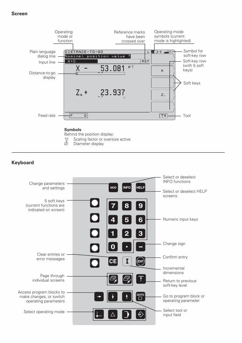
Screen
Keyboard
8 9
5 64
1 2 3
0
ENTCE
7
MOD INFO HELP
GOTO
5 soft keys(current functions are
indicated on screen)
Select or deselect HELPscreens
Numeric input keys
Change sign
Confirm entry
Incrementaldimensions
Select operating mode
Access program blocks tomake changes, or switch
operating parameters
Clear entries orerror messages
Page through individual screens
SymbolsBehind the position display: : Scaling factor or oversize active∅: Diameter display
Operatingmode orfunction
Plain languagedialog line
Soft-key row(with 5 softkeys)
Operating modesymbols (currentmode is highlighted)
Symbol forsoft-key row
Soft keys
Tool
Reference markshave been
crossed over
Feed rate
Input line
Distance-to-godisplay
Change parametersand settings
Select tool orinput field
Go to program block oroperating parameter
Return to previoussoft-key level
Select or deselectINFO functions

Software version
This User's Manual is for POSITIP 855 models with the followingsoftware version:
Progr. 246 xxx 03.
The x's can be any numbers. The software version of your unit isshown on a label on the rear panel.
This User 's Manual describes the POSITIP 855 forturning. A separate manual is available for milling.
Usage
This unit corresponds to class A in accordance with EN 55022 andwill be used predominantly in industrially zoned areas
About this manual
This manual is divided into two parts:
• Part I: Operating Instructions .... starts on page 5
• Part II: Technical Information ..... starts on page 57
Operating Instructions
When using the POSITIP 855 in your work, you need only refer tothe Operating Instructions (Part I).
If you're a beginner with POSITIP, you can use the operatinginstructions as a step-by-step workbook. This part begins with ashort introduction to the basics of coordinate systems and positionfeedback, and provides an overview of the available features. Eachfeature is explained in detail, using an example which you canimmediately try out on the machine — so you won't get "lost" toodeeply in the theory. As a beginner you should work through all theexamples presented.
If you're already an expert POSITIP user, you can use theoperating instructions as a comprehensive review and referenceguide. The clear layout and the subject index make it easy to findthe desired topics.
Technical Information
If you are interfacing the POSITIP 855 to a machine or wish to usethe data interfaces, refer to the technical information in Part II.
Subject Index
A subject index for both parts of this manual starts on page 86.

Dialog flowcharts
Dialog flowcharts are used for each example in this manual.They are laid out as follows:
This area explains the key function or work step.If necessary, supplementary information will also be included.
P r o m p t
This area explains the key function or work step.If necessary, supplementary information will also be included.
This area shows thekeys to press.
This area shows thekeys to press.
If there is an arrow at the end of the flowchart, this means that it continues onthe next page.
A prompt appears with some actions (not always) at the top of thescreen. In the flowcharts the prompts always have a graybackground.
If two flowcharts are divided by a broken line, this means that youcan follow the instructions either above or below the broken line.
Some flowcharts also show the screen that will appear after youpress the proper keys.
Abbreviated flowcharts
Abbreviated flowcharts supplement the examples and explana-tions. An arrow ( ⇒⇒⇒⇒⇒ ) indicates a new input or a work step.
Special Notes in This Manual
Especially important information is shown as a separate note in agray box. Pay special attention to these notes. Ignoring themwould prevent effective use of the control, or even result indamage to the tool or workpiece.
Symbols in the gray boxes
The symbols in the left of the gray boxes indicate the nature of theprovided information.
General information
for example on the machine tool.function
Information for the machine tool builderfor example that he must implement a certain function
Essential information
for example that a certain tool is needed for thedescribed function

Part I: Operating Instructions
I - 1 Fundamentals of Positioning ..................................................... 7
I - 2 Working with POSITIP – First Steps ........................................ 13
Before you start ............................................................................................... 13Switch-on ......................................................................................................... 13Operating modes ............................................................................................. 14The HELP, MOD and INFO functions .............................................................. 14Selecting soft-key functions ............................................................................. 15On-screen operating instructions ..................................................................... 15Error messages ................................................................................................ 16Selecting the unit of measurement .................................................................. 16Selecting position display modes ..................................................................... 17Entering tool data and setting the datum ......................................................... 18Displaying and moving to positions .................................................................. 22Turning with oversizes ..................................................................................... 22
I - 3 Programming POSITIP .............................................................. 27
Operating mode PROGRAMMING AND EDITING ........................................... 27Selecting a program ......................................................................................... 28Deleting programs ............................................................................................ 28Editing programs .............................................................................................. 29Entering program blocks .................................................................................. 30Calling tool data from a program ...................................................................... 32Transferring positions: Teach-in mode ............................................................. 33Multipass cycle ................................................................................................ 36Entering program interruptions ........................................................................ 38Subprograms and program section repeats ..................................................... 39Editing existing programs ................................................................................. 44Deleting program blocks .................................................................................. 45Transferring programs over the data interface ................................................. 46
I - 4 Executing Programs .................................................................. 49
I - 5 INFO: Pocket Calculator, Stopwatch, Taper Calculator ......... 51
To access the INFO functions .......................................................................... 51Taper calculator ................................................................................................ 52Stopwatch ........................................................................................................ 53Pocket calculator .............................................................................................. 53
I - 6 User Parameters: The MOD Function ...................................... 55
Scaling factors .................................................................................................. 55Entering user parameters ................................................................................. 56
Part II: Technical Information............................................................ 57
Subject Index...................................................................................... 86
I
Op
era
tin
g I
nstr
ucti
on
s

I - 1 Fundamentals of Positioning
POSITIP 855 Operating Instructions 7
Fig. 1: The Cartesian coordinate system
I - 1
Fundamentals of Positioning
You can skip this chapter if you are already familiar with theconcepts of coordinate systems, incremental and absolutedimensions, nominal and actual positions, and distance-to-go.
Introduction
The geometry of a workpiece is described by a rectangular orCartesian coordinate system (named in honor of the Frenchmathematician and philosopher René Descartes, in Latin RenatusCartesius, 1596 to 1650). The Cartesian coordinate system con-sists of three mutually perpendicular axes X, Y and Z. The point ofintersection of these axes is called the datum (or origin) of the co-ordinate system.
To determine positions on a workpiece, the coordinate system is“laid” onto the workpiece. With lathe work (i.e., rotationally sym-metrical workpieces), the Z axis move along the axis of rotationwhile the X axis moves in the direction of the radius or diameter.The Y axis can be disregarded since it would always have the samevalues as the X axis.
+Y
+X
+Z
–Z –Y
–X
Z
X
Fig. 2: The Cartesian coordinate system withlathe work

I - 1 Fundamentals of Positioning
8 Operating Instructions POSITIP 855
Datum setting
The workpiece drawing normally specifies the workpiece face asthe “absolute” datum, and indicates the axis of rotation. Thedatum setting procedure assigns the origin of the absolutecoordinate system to this datum.
ZX
T1 T2 T3
Determining and entering tool data
Your POSITIP display unit should show you the absolute positionof the workpiece regardless of the length and shape of theparticular tool being used. For this reason you must determinethe tool data (tool preset) and enter them. First touch theworkpiece with the cutting edge of the tool and then enter theassociated display value for that position.
You can enter tool data for up to 99 tools. When you have setthe datum for a new workpiece, all tool data are referenced tothe new workpiece datum.
See examples starting on page 19.
Cross slide, saddle and top slide
On conventional lathes, the tool is mounted on a slide that movesin the direction of the X axis (the cross slide) and in the direction ofthe Z axis (the saddle).
Most lathes have a top slide above the saddle. The top slidemoves in Z axis direction and is designated ZO.
Z
ZO
X
+Z
+X
+ZO
Fig. 3: Axes of movement on a lathe
Fig. 4: The origin of the Cartesian coordinatesystem is the workpiece datum
Fig. 5: These tools have different tool data
I - 1 Fundamentals of Positioning
POSITIP 855 Operating Instructions 9
2
Z
X
15
5
35
65
1
0
Z
X
1
10
53530
2 3
IS
Z
X
R
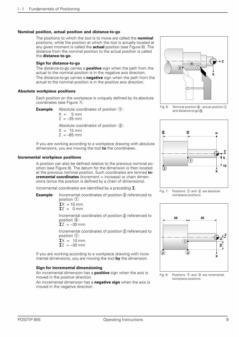
Nominal position, actual position and distance-to-go
The positions to which the tool is to move are called the nominalpositions, while the position at which the tool is actually located atany given moment is called the actual position (see Figure 6). Thedistance from the nominal position to the actual position is calledthe distance-to-go.
Sign for distance-to-go
The distance-to-go carries a positive sign when the path from theactual to the nominal position is in the negative axis direction.The distance-to-go carries a negative sign when the path from theactual to the nominal position is in the positive axis direction.
Absolute workpiece positions
Each position on the workpiece is uniquely defined by its absolutecoordinates (see Figure 7).
Example: Absolute coordinates of position :X = 5 mmZ = –35 mm
Absolute coordinates of position :X = 15 mmZ = –65 mm
If you are working according to a workpiece drawing with absolutedimensions, you are moving the tool to the coordinates.
Incremental workpiece positions
A position can also be defined relative to the previous nominal po-sition (see Figure 8). The datum for the dimension is then locatedat the previous nominal position. Such coordinates are termed in-cremental coordinates (increment = increase) or chain dimen-sions (since the position is defined by a chain of dimensions).
Incremental coordinates are identified by a preceding I.
Example: Incremental coordinates of position referenced toposition :IX = 10 mmIZ = 0 mm
Incremental coordinates of position referenced toposition :IZ = –30 mm
Incremental coordinates of position referenced toposition :IX = 10 mmIZ = –30 mm
If you are working according to a workpiece drawing with incre-mental dimensions, you are moving the tool by the dimension.
Sign for incremental dimensioning
An incremental dimension has a positive sign when the axis ismoved in the positive direction.An incremental dimension has a negative sign when the axis ismoved in the negative direction.
Fig. 6: Nominal position , actual positionand distance-to-go
Fig. 7: Positions and are absoluteworkpiece positions
Fig. 8: Positions and are ncrementalworkpiece positions
1
3
1
2
S I
R
1 2
1 3
1
3
2
2

I - 1 Fundamentals of Positioning
10 Operating Instructions POSITIP 855
Example: Workpiece drawing with absolute dimensions
(in accordance with ISO 129 standard)
40
Z
X
80
60
80
60
100
120
180
220
180
150
120
80
40 0
P0
P1
P2P3
P4
P5
P6P7
A list of coordinates corresponding to this example is advantageous whenyou are working in the PROGRAMMING AND EDITING operating mode.The X-coordinate values are given as diameters.
Coordinates X∅∅∅∅∅ Z Remarksfor [mm] [mm]
P0 40 0 Face
P1 80 – 40
P2 60 – 80 Recess
P3 60 – 120 Recess
P4 100 – 120
P5 120 – 150
P6 180 – 180
P7 180 – 220

I - 1 Fundamentals of Positioning
POSITIP 855 Operating Instructions 11
Position encoders
The position encoders convert the movements of the machineaxes into electrical signals. POSITIP then evaluates these signals,determines the actual position of the machine axes, and displaysthe position as a numerical value.
If power is interrupted, the relationship between the machine axispositions and the calculated actual positions is lost. The referencemarks on the position encoders and the reference mark evaluationfeature (REF) enable POSITIP to re-establish this relationship againwhen the power is restored.
Reference marks
The scales of the position encoders contain one or several refer-ence marks. When a reference mark is crossed over, a signal isgenerated identifying that position as a reference point(scale datum = machine datum).
When this reference mark is crossed over, the POSITIP's refer-ence mark evaluation feature restores the relationship betweenaxis slide positions and display values as you last defined it by set-ting the datum. If the linear encoders have distance-coded refer-ence marks, you only need to move the machine axes a maximumof 20 mm to do this.
Z
Fig. 10: Linear scales: with distance-codedreference marks (upper illustration)and one reference mark (lowerllustration)
Fig. 9: Linear encoder, here for the Z axis

I - 1 Fundamentals of Positioning
12 Operating Instructions POSITIP 855
NOTES

I - 2 Working with POSITIP – First Steps
POSITIP 855 Operating Instructions 13
I - 2
Switch-on
Turn on the powerandpress any key.
Cross over the reference marks in all axes(in any sequence).
Do not cross over the reference marks.Note: In this case the relationship between axis slide positions anddisplay values will be lost if the power is interrupted.
Your POSITIP is now ready for operation and is in the operatingmode ACTUAL VALUE.
Working with POSITIP – First Steps
Before you start
You can cross over the reference marks after every switch-on.REF appears in the input line on the screen when all the referencemarks have been crossed over. If you set a new datum, POSITIPautomatically stores the new relationship between axis slide posi-tions and display values.
Working without reference mark evaluation
You can also use POSITIP without crossing over the referencemarks — simply press the soft key No REF.
Note that if you do not cross over the reference marks,a new datum point you set will not be stored. Thismeans that after a power interruption the relationshipbetween axis slide positions and display values cannotbe restored.
Fig. 11: REF display on screen
0 ➤➤➤➤➤ 1

I - 2 Working with POSITIP – First Steps
14 Operating Instructions POSITIP 855
The HELP, MOD and INFO functions
You can call the HELP, MOD and INFO functions at any time.
To call a function:➤➤➤➤➤ Press the key for the desired function.
To leave a function:➤➤➤➤➤ Press the same key again.
You can switch to another operating mode at any time by pressingthe key for the desired mode.
Operating Modes
The operating mode determines which functions are available toyou.
Available functions Mode Key
Position display for basic ACTUALmachining tasks; VALUETool presetting;Datum setting
Distance-to-go display; DISTANCE-Turning with oversize TO-GO
Storage of work steps for PROGRAMMINGsmall-lot production AND EDITING
Run programs previously EXECUTEcreated in the PROGRAMMING PROGRAMAND EDITING mode
Available functions Function name Key
On-screen operating instruc- HELPtions: graphics and textkeyed to the current screencontents
User parameters: MODTo redefine POSITIP's basicoperating characteristics
Taper calculator, stopwatch, INFOpocket calculator
HELP
MOD
INFO

I - 2 Working with POSITIP – First Steps
POSITIP 855 Operating Instructions 15
Whenever you press the key for an operating mode,POSITIP displays the soft keys with the mainfunctions for that mode.
On-screen operating instructions
The integrated operating instructions provide you with informationand assistance in any situation.
To call the operating instructions:➤➤➤➤➤ Press the HELPHELPHELPHELPHELP key.➤➤➤➤➤ Use the paging keys if the explanation is spread over more
than one screen page.
To leave the operating instructions:➤➤➤➤➤ Press HELP HELP HELP HELP HELP again.
Example: On-screen operating instructions for NOTE/SET
The function NOTE/SET is described in this manual starting onpage 21.
➤➤➤➤➤ Select NOTE/SET by pressing the soft key Note/Set inthe operating mode ACTUAL VALUE.
➤➤➤➤➤ Press HELP.The first page of the operating instructions for NOTE/SET ap-pears on the screen.
Page reference at the lower right of the screen:The number in front of the slash is the current page; thenumber behind the slash is the total number of pages for thistopic. The on-screen operating instructions now contain the fol-lowing information on NOTE/SET:• General information on the function (page 1/2)• Sequence of entries (page 2/2)
To leave the operating instructions:➤➤➤➤➤ Press HELP again.
Selecting soft-key functions
The soft-key functions are grouped into one or more rows. Thenumber of rows is indicated by a symbol at the upper right of thescreen. If no symbol is shown, that means there is only one rowfor the function. The highlighted rectangle in the symbol indicatesthe current row being displayed.
Fig. 12: The symbol for soft-key rows.Here, the first row is being dis-played
Fig. 13: On-screen operating instructions forNOTE/SET (page 1 of 2)
Function Key
Page forward through the soft-key rows
Page backward through the soft-key rows
Go back one level
Fig. 14: On-screen operating instructions forNOTE/SET (page 2 of 2)

I - 2 Working with POSITIP – First Steps
16 Operating Instructions POSITIP 855
Error messages
If an error occurs while you are working with POSITIP, a messagewill come up on the screen in plain English.
To call an explanation of the error:➤➤➤➤➤ Press the HELP key.
To clear the error message:➤➤➤➤➤ Press the CE key.
Blinking error messages
W A R N I N G
Blinking error messages mean that the operationalreliability of the POSITIP has been impaired.
If a blinking error message occurs:➤➤➤➤➤ Note down the error message displayed on the screen.➤➤➤➤➤ Switch off the power to the POSITIP.➤➤➤➤➤ Attempt to correct the problem with the power off.➤➤➤➤➤ If the blinking error message recurs, notify your customer
service agency.
Selecting the unit of measurement
Positions can be displayed in millimeters or inches. If you chooseinches, inch will be displayed at the top of the screen next toREF.
To change the unit of measurement:➤➤➤➤➤ Press MOD.➤➤➤➤➤ Page to the soft key row containing the user parameter
mm or inch.➤➤➤➤➤ Choose the soft key mm or inch to change to the other unit.➤➤➤➤➤ Press MOD again.
For more information on user parameters, see Chapter I - 6.
Fig. 15: The inch indicator

I - 2 Working with POSITIP – First Steps
POSITIP 855 Operating Instructions 17
20
Z
1
X
40
40
0 +10 +25
Z
Z
-10 0 +15
Z0Z
Z0
1
1
Selecting position display modes
Radius/diameter display
Drawings for lathe parts usually give diameter values. When youturn the part, however, you infeed the tool in radius values.POSITIP can display either the radius or the diameter for you.When the diameter is being displayed, the diameter symbol (∅) isshown next to the position value.
Example: Radius display, position X = 20 mmDiameter display, position X = 40∅ mm
To switch over the display
➤➤➤➤➤ Press MOD.➤➤➤➤➤ Page with the paging keys to the soft key row containing
Radius or Dia.➤➤➤➤➤ Press this soft key to switch from radius to diameter display
or vice-versa.
Separate value/sum display
Separate value displayIn this display mode the positions of the saddle and top slide aredisplayed separately. The position displays are referenced to thedatum points which you set for the axes. When an axis slidemoves, only the position display for that axis changes.The top slide is identified with a small O, for example ZO.
Sum displayIn this mode the position values of the saddle and top slide areadded together. The sum display shows the absolute position ofthe tool, referenced to the workpiece datum.When the sum display mode is active, a small S is shown next tothe axis designation, for example ZS.
Example: Separate value (see Fig. 17): Z = +25.000 mmZO = +15.000 mm
Sum display (see Fig. 17): ZS = +40.000 mm
The sum display will show correct values only if the actual position values of both axis slides were correctly addedand entered (with sign) when setting the datum for the“sum.”
To switch over the display
➤➤➤➤➤ Press MOD.➤➤➤➤➤ Page with the paging keys to the soft key row containing Sum
or Seprt.➤➤➤➤➤ Press this soft key to switch from separate value display to
sum display or vice-versa.
Fig. 16: Workpiece for radius/diameter displayexample
Fig. 17: Workpiece for separate value/sumdisplay example

I - 2 Working with POSITIP – First Steps
18 Operating Instructions POSITIP 855
Entering tool data and setting the datum
Before you can use a tool you must enter its tool data (cuttingedge position). You can enter the data for up to 99 tools. A work-piece datum must also be entered before you can start machining.Normally the workpiece face (flat surface) is given the value Z = 0.
“ Freezing” a position when turning the first diameter
If you want to measure the diameter of the workpiece after turningthe first diameter, you can store (“freeze”) the actual positionbefore retracting the tool. This is done in the ACTUAL VALUEoperating mode with the Note/Set function. See page 21 for anexplanation of this function and an example.
Tool table
When you preset tools, POSITIP automatically stores the tool datain a table. You can access the tool table with a user parameter.If you change values in the table, the position display will no longershow the values it displayed after tool presetting.
Selecting tools
The number of the current tool is shown in a small box at thelower right of the screen (next to the letter T). Use the verticalarrow keys to select another tool.

I - 2 Working with POSITIP – First Steps
POSITIP 855 Operating Instructions 19
D a t u m S e t t i n gZS = +0
Z
Z=0
Operating mode: ACTUAL VALUE
Machine the workpiece face.Leave the cutting edge of the tool at the face.
Page to the function Datum./
Select Datum.
Select the axis (ZS).
Example: Setting the workpiece datum (zero point)
The datum is set to zero for the sum display of the Z axis. All tooldata entered are automatically referenced to this datum.
Preparation:
➤➤➤➤➤ Select the tool number (tool data) with the vertical arrow keys.
Enter a value, for example 10. Confirm entry.
Set the datum (workpiece face) to the indicated value.
ENT01
ENT
Entering tool data and setting the datum
I - 2 Working with POSITIP – First Steps
20 Operating Instructions POSITIP 855
Touch the workpiece face with the tool.
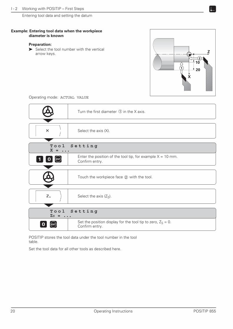
Example: Entering tool data when the workpiece
diameter is known
Preparation:
➤➤➤➤➤ Select the tool number with the verticalarrow keys.
Operating mode: ACTUAL VALUE
Z
20
102
1
X
Entering tool data and setting the datum
Turn the first diameter in the X axis.
Select the axis (X).
T o o l S e t t i n gX = ...
1 0 ENTEnter the position of the tool tip, for example X = 10 mm.Confirm entry.
Select the axis (ZS).
T o o l S e t t i n gZS = ...
POSITIP stores the tool data under the tool number in the tooltable.
Set the tool data for all other tools as described here.
0 ENTSet the position display for the tool tip to zero, ZS = 0.Confirm entry.
1
2

I - 2 Working with POSITIP – First Steps
POSITIP 855 Operating Instructions 21
Example: Entering tool data when the workpiece
diameter is unknown
Turn the first diameter and freeze the tool position with Note.Then retract the tool, measure the diameter and set the frozenposition to the measured value.
The value to be entered will depend on whether youhave selected radius or diameter display.
Preparation:
➤➤➤➤➤ Select the tool number with the vertical arrow keys.
?
1
Z
?
X
2
Entering tool data and setting the datum
Operating mode: ACTUAL VALUE
Select the axis, for example X.
Turn the first diameter in the X axis.
Freeze the position.
Retract, for example to position .
Measure the workpiece.
E n t e r v a l u e f o r X+ 0
1 5 ENTEnter the measured diameter or radius, for example 15 mm.Confirm entry.
T u r n 1 s t d i a m e t e r i n X a x i s
POSITIP stores the tool data under the tool number in the tooltable.
To cancel the Note/Set function
Press the soft key Escape.You can cancel the function at any time.
Select Note/Set.
2

I - 2 Working with POSITIP – First Steps
22 Operating Instructions POSITIP 855
Z
X
Displaying and moving to positions
Distance-to-go
Although it is often sufficient to have POSITIP display the coordi-nates of the actual position of the tool, it is usually better to usethe distance-to-go feature — this enables you to approach nomi-nal positions simply by traversing to display value zero. Even whenworking with distance-to-go you can enter coordinates in absoluteor incremental dimensions.
Graphic positioning aid
When you are traversing to display value zero, POSITIP displays agraphic positioning aid (see Figure 18).
The graphic positioning aid is located in a rectangle just below thedisplay for the active axis. Two triangular marks in the center ofthe rectangle symbolize the nominal position you want to reach.
The small square symbolizes the axis slide. An arrow indicating thedirection appears in the square while the axis is moving, so youcan easily tell whether you are moving towards or away from thenominal position.
Note that the square does not begin to move until the axis slide isnear the nominal position.
Turning with oversizes
You enter oversizes in the user parameters (see Chapter I - 6).Oversizes are automatically taken into account in the distance-to-go mode. When the displayed distance-to-go is 0, only the finishingallowance remains to be machined.
When you have set the user parameter Oversize On/Off toOn, a symbol for oversize ( ) appears behind the display value.
C A U T I O N
will also appear if you've activated a scaling factor forthe axis. If the symbol appears but you're not surewhether it indicates a scaling factor or an oversize,check the settings of the user parameters.
Entry values for oversize or undersize
Oversize: Positive entry value (up to 999.999 mm).Undersize: Negative entry value (down to –999.999 mm).
Fig. 18: The graphic positioning aid
Fig. 29: Oversizes for X and Z
POSITIP can show the absolute position instead of thegraphic positioning aid. You can switch between the twomodes with operating parameter P 91 (see Chapter II - 2).

I - 2 Working with POSITIP – First Steps
POSITIP 855 Operating Instructions 23
Entering oversizes
➤➤➤➤➤ Press MOD.➤➤➤➤➤ Scroll to the user parameter Oversize.➤➤➤➤➤ Press the soft key Oversize X (for example).➤➤➤➤➤ Enter the desired oversize for the axis (including the sign).➤➤➤➤➤ Press ENT.
This returns you to the main menu for the user parameters.➤➤➤➤➤ If desired, enter an oversize for the second axis.➤➤➤➤➤ Switch the soft key Ovrsize ON / OFF to ON.
This activates the oversizes you entered.➤➤➤➤➤ Leave the user parameters:
Press MOD.
The entered oversizes will now be taken into account when youtraverse to display value zero with the distance-to-go display.
To deactivate oversizes
When you want to work without oversizes again:➤➤➤➤➤ Switch the soft key Ovrsize ON / OFF to
OFF, or enter 0 for the oversize.
Example: Effect of an oversize in the X axis
1. Diameter display for X, positionPosition of the tool cutting edge:
without oversize: X∅ = +40.000 mmwith oversize (+2.000 mm): X∅ = +44.000 mmwith undersize (–2.000 mm): X∅ = +36.000 mm
2. Radius display for X, positionPosition of the tool cutting edge:
without oversize: X = +50.000 mmwith oversize (+2.000 mm): X = +52.000 mmwith undersize (–2.000 mm): X = +48.000 mm
C A U T I O NWhen the soft key Ovrsize ON / OFF is set to ONoversizes will be effective on every position which youmove to with DISTANCE-TO-GO.
1
2
Z
X
10
0
40
Displaying and moving to positions
Fig. 21: Workpiece drawing for the example onOversizes. Tool positions without over-size or undersize
Fig. 20: Entering an oversize
MOD
2
1

I - 2 Working with POSITIP – First Steps
24 Operating Instructions POSITIP 855
Displaying and moving to positions
Z
1
X
152
34
20
45
05
Select the axis (X).
Enter the coordinate for nominal position : X = 15 mm. Confirm entry.The positioning aid appears for the X axis;the nominal position remains at the top of the screen.
1 5 ENT
Move the X axis until the display value is zero.
Select the axis ( ZS ).
Enter the coordinate for nominal position : ZS = –20 mm. Confirm entry.The positioning aid appears for the ZS axis;the nominal position remains at the top of the screen.
2 ENT0
Move the ZS axis until the display value is zero.
1
N o m i n a l p o s i t i o n v a l u e ?X + ....
N o m i n a l p o s i t i o n v a l u e ?ZS + ....
1
2
3
Example: Turning a shoulder by traversing to display value zero
In this example, both incremental and absolute nominal positionvalues are used.
Position Z = 0 mm X = 15 mmPosition Z = –20 mm X = 15 mmPosition Z = –20 mm IX = +5 mmPosition IZ = –45 mm IX = 0 mm
Preparation:
➤➤➤➤➤ Preset the tool and set the workpiece datum as describedearlier in this chapter.
➤➤➤➤➤ Set the user parameters (see Chapter I - 6):• Sum display ZS or for both axes (XS and ZS)• Radius display for both axes X and Z• Set Ovrsize ON / OFF to OFF
➤➤➤➤➤ Preposition the tool appropriately(such as X = +20 mm, Z = +10 mm).
If you want to turn a larger shoulder, use the Multipasscycle (see Chapter I - 3). This cycle allows you to turnthe shoulder in any number of infeeds without having toenter coordinates for each feed move.
Operating mode: DISTANCE-TO-GO
2
4

I - 2 Working with POSITIP – First Steps
POSITIP 855 Operating Instructions 25
Displaying and moving to positions
Select the axis (X).
Enter the coordinate for nominal position : 5 mm andmark the entry as an incremental dimension: IX = 5 mm.Confirm entry.The positioning aid appears for the X axis;the nominal position remains at the top of the screen.
Move the X axis until the display value is zero.
Select the axis (ZS).
Enter the coordinate for nominal position : ZS = –45 mm andmark the entry as an incremental dimension: IZS = –45 mm.Confirm entry.The positioning aid appears for the ZS axis;the nominal position remains at the top of the screen.
ENT
4 5
Move the ZS axis until the display value is zero.
5
N o m i n a l p o s i t i o n v a l u e ?ZS + ....
ENT
N o m i n a l p o s i t i o n v a l u e ?X + ....
3
4

I - 2 Working with POSITIP – First Steps
26 Operating Instructions POSITIP 855
NOTES

I - 3 Programming POSITIP
POSITIP 855 Operating Instructions 27
Fig. 22: The main menu in the operating modePROGRAMMING AND EDITING
I - 3
Programming POSITIP
Operating mode PROGRAMMING AND EDITING
The available functions in the PROGRAMMING AND EDITINGoperating mode are divided into four groups:• Programming mode
for entering, running and editing programs• Teach-in mode• External mode
for transferring programs to an external device• Deleting programs
Programs contain the work steps for workpiece machining. Youcan edit programs, add work steps to them and run them as oftenas you wish. POSITIP can store a maximum of 20 programs with atotal of 2000 nominal positions. A single program can contain amaximum of 1000 nominal positions.
The External mode enables you to store programs with theHEIDENHAIN FE 401 floppy disk unit and load them into POSITIPagain on demand — you don't need to re-enter them manually.You can also transfer programs to a personal computer or printer.
Programmable functions
• Nominal position values (axes with saddle and top slides:nominal value of the summed position, see “Selecting positiondisplay modes” in Chapter I - 2)
• Interrupt program• Multipass cycle:
Turning with any number of feed moves.• Program section repeats:
A section of a program only has to be entered once and canthen be run up to 999 times in succession.
• Subprogramming:A section of a program only has to be entered once and canthen be run at various places in the program.
Transfer position: Teach-in mode
This mode allows you to transfer the actual positions of the tooldirectly into a program. In many cases the Teach-in function willsave you considerable keying effort.
What happens with finished programs?
For workpiece machining, programs are run in the operating modeEXECUTE PROGRAM. See Chapter I - 4 for an explanation of thismode.

I - 3 Programming POSITIP
28 Operating Instructions POSITIP 855
Selecting a program
Each program is identified by a number between 0 and 99 999 999which you assign it.
Operating mode: PROGRAMMING AND EDITING
Go to the program directory.
Select an existing program, such as program number 5.5
1
P r o g r a m n u m b e r ?
Create a new program:Give it a number which is not yet in the directory, such as 19.9
Choose the unit of measurement.
ENTConfirm your entry.The selected program can now be entered, edited or run.
Program directory
The program directory appears when you choose the soft keyProgram Number. The number in front of the slash is the pro-gram number, the number behind the slash is the numberof blocks in the program.
A program always contains at least two blocks.
To delete a program
If you no longer wish to keep a program in memory, you candelete it:➤➤➤➤➤ In the operating mode PROGRAMMING AND EDITING, press
the soft key Delete Program in the first soft key row.➤➤➤➤➤ Enter the program number.➤➤➤➤➤ Press ENT to delete the program.

I - 3 Programming POSITIP
POSITIP 855 Operating Instructions 29
Editing programs
Operating mode: PROGRAMMING AND EDITING
Use the paging keys to display the programmable functions in thedifferent soft key rows. The screens shown at the right alreadycontain some program blocks. Turn to the next page of this manualto learn how program blocks are entered.
Edit the last program selectedwith Program Number,such as program number 10.
/
/
/
The first soft key row providesfunctions for entering and changingcoordinates.
The third soft key row contains theMultipass cycle for turning withany number of feed moves.
The second soft key row providesthe following functions:• Enter labels for subprograms
and program section repeats• Interrupt program• Call tool data• Delete program blocks

I - 3 Programming POSITIP
30 Operating Instructions POSITIP 855
Entering program blocks
Current block
The current block is shown between the two dashed lines. Newblocks are inserted behind the current block. When the END PGMblock is between the dashed lines, no new blocks can be inserted.
Going directly to a program block
Scrolling to the desired block with the arrow keys can be time-consuming with long programs. A quicker way is to use the GOTOfunction. This enables you to move directly to the block you wishto change or add new blocks behind.
Operating mode: PROGRAMMING AND EDITING
Select Edit.
GOTO
Enter a block number, such as 58.5 8
Confirm your entry.Block number 58 is now the current block.
B l o c k n u m b e r ?
ENT
Press the GOTO key.
Function Soft key/Key
Go up one block
Go down one block
Cancel numerical entry
Delete current block
CE

I - 3 Programming POSITIP
POSITIP 855 Operating Instructions 31
Entering program blocks
Z
1
X
152
34
2065
05
Select the coordinate axis (X axis).
N o m i n a l p o s i t i o n v a l u e ?
1 5 ENT
Program blocks
0 BEGIN PGM 10 MM Start of program, program number and unit of measurement1 X+50.000 Pre-position the tool in the X axis2 Z+20.000 Pre-position the tool in the Z axis3 X+15.000 X coordinate, position4 Z–20.000 Z coordinate, position5 IX+5.000 Incremental X coordinate, position6 Z–65.000 Z coordinate, position7 END PGM 10 MM End of program, program number and unit of measurement
Example: Milling a shoulder
The datum is the workpiece zero.
Position Z = 0 mm X = 15 mmPosition Z = –20 mm X = 15 mmPosition Z = –20 mm IX = +5 mmPosition Z = –65 mm X = 20 mm
Summary of programming steps
➤➤➤➤➤ In the main menu PROGRAMMING AND EDITING use theProgram Number soft key to access the program directory.
➤➤➤➤➤ Key in the number of the program you want to work on, andpress ENT.
➤➤➤➤➤ Select Edit in the main menu PROGRAMMING ANDEDITING.
➤➤➤➤➤ Enter the nominal positions.
Running a finished program
When a program is finished it can be run in the EXECUTE PRO-GRAM operating mode (see Chapter I - 4).
Example of entry: Entering a nominal position into a program(block 3 in the example)
1
1
2
4
Enter the nominal position value (X = 15 mm). Confirm entry.The nominal position is now the current block (between the dashed lines).
3
2
3
4

I - 3 Programming POSITIP
32 Operating Instructions POSITIP 855
ENT4
Call tool data from the tool table.
Operating mode: PROGRAMMING AND EDITING
T o o l n u m b e r ?
Calling tool data from a program
Chapter I - 2 explained how to enter tool data (lengths) into the tooltable.
The tool lengths stored in the table can also be called from a pro-gram — you don't need to select the new tool lengths from the ta-ble with the vertical arrow keys every time you change the toolduring program run.
The TOOL CALL command automatically pulls the tool lengthsfrom the table.
If you enter a different tool axis in the program than isstored in the table, POSITIP will store the new tool axisin the table.
Enter the tool number (4, for example) under which the tool lengths are storedin the tool table. Confirm your entry.
Fig. 23: The tool table on the screen

I - 3 Programming POSITIP
POSITIP 855 Operating Instructions 33
1 5 ENT
Move the entered axis until the display value is zero.Then enter and transfer further coordinates.
Enter the nominal position value (X = 15 mm). Confirm entry.POSITIP displays the positioning aid for traversing to zero. The enterednominal position value appears in the input line at the top of the screen.
Transferring positions: Teach-in mode
Teach-in programming offers the following two options:• Enter nominal position, transfer nominal position into program,
move to positions by traversing to display value zero:TEACH-IN / DISTANCE TO GO
• Move to a position and transfer the actual value into a program:TEACH-IN / ACTUAL POSITION
You can change transferred position values with TEACH-IN /PROGRAM.
Preparation
➤➤➤➤➤ With Program number select the program you want totransfer positions into.
➤➤➤➤➤ Select the tool number (tool data) with the vertical arrow keys.
Programming example for TEACH-IN / DISTANCE TO GOGenerating a program while turning a shoulder
With Teach-in you machine a workpiece according to the work-piece drawing. POSITIP transfers the nominal position coordinatesdirectly into the program while you machine. Pre-positioning andretraction moves can be selected as desired and entered like draw-ing dimensions.
Position Z = 0 mm X = 15 mmPosition Z = –20 mm X = 15 mmPosition Z = –20 mm IX= +5 mmPosition Z = –65 mm X = 20 mm
Operating mode: PROGRAMMING AND EDITING
Z
1
X
152
34
2065
05
Select Teach-In.The functions for TEACH-IN / DISTANCE TO GOare available immediately in the first soft key row.
Example: Transfer the X coordinate of corner point into aprogram.
Select the coordinate axis (X).
N o m i n a l p o s i t i o n v a l u e ?
4
3
2
1
1

I - 3 Programming POSITIP
34 Operating Instructions POSITIP 855
T r a n s f e r a c t u a l v a l u e X ?
Transferring positions: Teach-in mode
Operating mode: PROGRAMMING AND EDITING
Select Teach-In.
Z
X
Go to TEACH-IN / ACTUAL POSITION./
Example: : : : : Transfer the depth of a groove
Select the coordinate axis (X).
Machine the groove on the workpiece.
ENTTransfer the actual value for the X axis into the program. The transferredprogram block appears in the input line at the top of the screen.
Programming example for TEACH-IN / ACTUAL POSITIONTransfer position and depth of grooves into a program
With TEACH-IN / ACTUAL POSITION you can generate a pro-gram that contains the actual positions of the tool.
I - 3 Programming POSITIP
POSITIP 855 Operating Instructions 35
Transferring positions: Teach-in mode
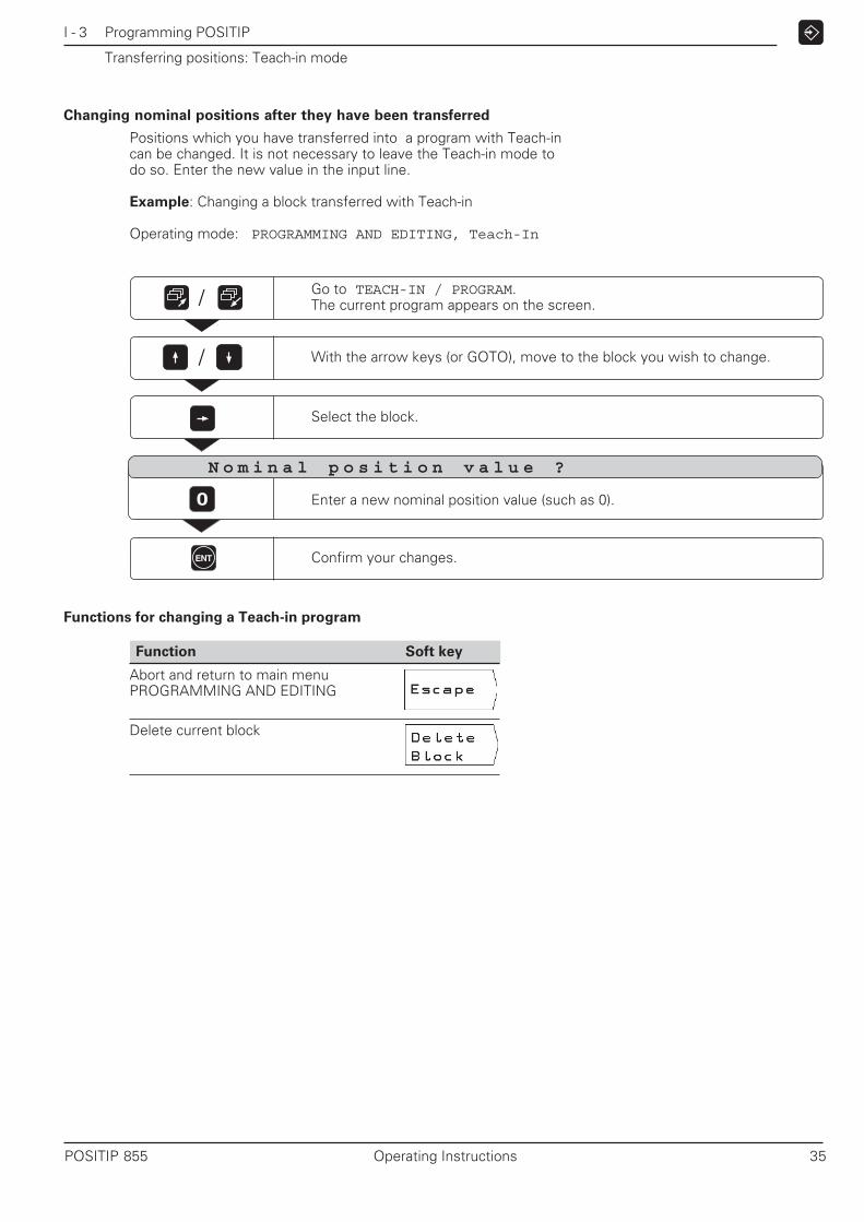
Changing nominal positions after they have been transferred
Positions which you have transferred into a program with Teach-incan be changed. It is not necessary to leave the Teach-in mode todo so. Enter the new value in the input line.
Example: Changing a block transferred with Teach-in
Operating mode: PROGRAMMING AND EDITING, Teach-In
Confirm your changes.ENT
0 Enter a new nominal position value (such as 0).
/
With the arrow keys (or GOTO), move to the block you wish to change./
Select the block.
N o m i n a l p o s i t i o n v a l u e ?
Functions for changing a Teach-in program
Go to TEACH-IN / PROGRAM.The current program appears on the screen.
Function Soft key
Abort and return to main menuPROGRAMMING AND EDITING
Delete current block

I - 3 Programming POSITIP
36 Operating Instructions POSITIP 855
Multipass cycle
The multipass cycle enables you to turn a shoulder in any numberof infeeds.
You only need to enter three blocks into a program:
• CYCL block• X coordinate• Z coordinate
The multipass cycle contains all information required for the opera-tion.
Do not delete any blocks from the cycle.
When the program is run, POSITIP always displays the distance-to-go to the two nominal positions immediately following the CYCLblock.
Example: Entering the Multipass cycle into a program
Operating mode: PROGRAMMING AND EDITING
Example: Turning a shoulder in any number of infeeds
Workpiece diameterbefore machining: X = 50 mm
Shoulder diameter: X = 10 mm
Start of shoulder: Z = 0 mm
End of shoulder: Z = –30 mm
Go to the third soft key row.
Select Edit.
/
Select the Multipass cycle.The program block CYCL 3.0 MULTIPASS appears on the screen.
Z
30
X
10
50
0
I - 3 Programming POSITIP
POSITIP 855 Operating Instructions 37
Multipass cycle
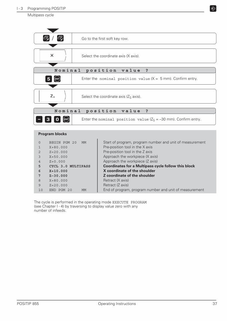
Go to the first soft key row./
Select the coordinate axis (X axis).
N o m i n a l p o s i t i o n v a l u e ?
ENT5
Select the coordinate axis (ZS axis).
N o m i n a l p o s i t i o n v a l u e ?
ENT3 0
Program blocks
0 BEGIN PGM 20 MM Start of program, program number and unit of measurement1 X+80.000 Pre-position tool in the X axis2 Z+20.000 Pre-position tool in the Z axis3 X+50.000 Approach the workpiece (X axis)4 Z+0.000 Approach the workpiece (Z axis)5 CYCL 3.0 MULTIPASS Coordinates for a Multipass cycle follow this block
6 X+10.000 X coordinate of the shoulder
7 Z–30.000 Z coordinate of the shoulder
8 X+80.000 Retract (X axis)9 Z+20.000 Retract (Z axis)10 END PGM 20 MM End of program, program number and unit of measurement
The cycle is performed in the operating mode EXECUTE PROGRAM(see Chapter I - 4) by traversing to display value zero with anynumber of infeeds.
Enter the nominal position value (X = 5 mm). Confirm entry.
Enter the nominal position value (ZS = –30 mm). Confirm entry.

I - 3 Programming POSITIP
38 Operating Instructions POSITIP 855
Entering program interruptions
You can divide a program into sections with stop marks. POSITIPthen executes the next block only after you press the soft keyNext Block.
Operating mode: PROGRAMMING AND EDITING
Press STOP to insert a program interruption.
Go to the second soft key row.
Select Edit.
/

I - 3 Programming POSITIP
POSITIP 855 Operating Instructions 39
Subprograms and program section repeats
Subprograms and program section repeats only need to be enteredonce in the program. You can then run them up to 999 times.
Subprograms can be run at any point in the program; program sec-tion repeats are run several times in direct succession.
Inserting program marks (labels)
You mark subprograms and program section repeats with labels(abbreviated in the program with LBL).
Labels 1 to 99
Labels 1 to 99 mark the beginning of a subprogram or programsection repeat.
Label 0Label 0 is used only to identify the end of a subprogram.
Label callIn the program, subprograms and program section repeats arecalled with the command CALL LBL.The command CALL LBL 0 is not allowed.
Subprogram:A subprogram called with CALL LBL is executed immediately af-ter the CALL LBL block.
Program section repeat:The program section located before the CALL LBL block is ex-ecuted. You enter the number of desired repeats with the CALLLBL command.
Nesting program sections
Subprograms and program section repeats can also be “nested.”For example, a subprogram can in turn call another subprogram orrepeat a program section repeat.
Maximum nesting depth: 8 levels.
Fig. 24: On-screen operating instructions forsubprograms (page 5 of 5)
Fig. 25: On-screen operating instructions forprogram section repeats (page 3 of 5)
I - 3 Programming POSITIP
40 Operating Instructions POSITIP 855
Subprograms and program section repeats
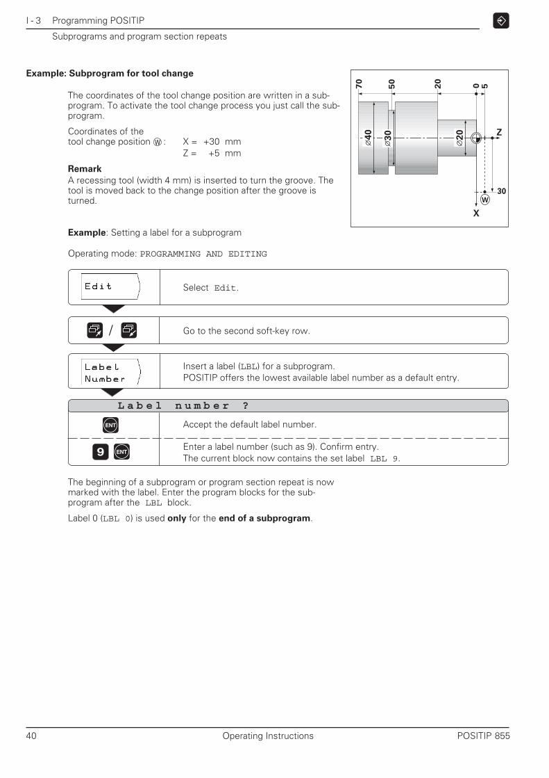
Example: Subprogram for tool change
The coordinates of the tool change position are written in a sub-program. To activate the tool change process you just call the sub-program.
Coordinates of thetool change position : X = +30 mm
Z = +5 mm
Remark
A recessing tool (width 4 mm) is inserted to turn the groove. Thetool is moved back to the change position after the groove isturned.
Go to the second soft-key row.
Select Edit.
Insert a label (LBL) for a subprogram.POSITIP offers the lowest available label number as a default entry.
L a b e l n u m b e r ?
/
Example: Setting a label for a subprogram
Operating mode: PROGRAMMING AND EDITING
ENT
9 ENTEnter a label number (such as 9). Confirm entry.The current block now contains the set label LBL 9.
The beginning of a subprogram or program section repeat is nowmarked with the label. Enter the program blocks for the sub-program after the LBL block.
Label 0 (LBL 0) is used only for the end of a subprogram.
Accept the default label number.
30
20
W
X
Z
50
70
0 5
20
40
30
W

I - 3 Programming POSITIP
POSITIP 855 Operating Instructions 41
For subprograms you can ignore the question “Repeat REP ?”.Press the soft key to confirm that a subprogram is being called.
Example: Entering a subprogram call – CALL LBL
Subprograms and program section repeats
Go to the second soft-key row./
L a b e l n u m b e r ?
ENT
9
Accept the default label number.
Enter the label number (9). Confirm entry.The current block now contains the called label LBL 9.
Program blocks
0 BEGIN PGM 30 MM Start of program, program number and unit of measurement
1 LBL 9 Beginning of subprogram 92 X+60.000 X coordinate of the tool change position (diameter)3 Z+5.000 Z coordinate of the tool change position4 LBL 0 End of subprogram 9
5 Z+2.000 Pre-position, Z coordinate6 X+64.000 Pre-position, X coordinate
7 CYCL 3.0 MULTIPASS Coordinates for a multipass cycle follow8 X+20.000 X coordinate of the first shoulder (for the diameter)9 Z–20.000 Z coordinate of the first shoulder
10 X+40.000 X coordinate of the second shoulder (diameter)11 Z–70.000 Z coordinate of the second shoulder
12 CALL LBL 9 Call subprogram 9: go to tool-change position,blocks 1 to 4 are executed
13 STOP Program interruption for tool change
14 Z–52.000 Pre-positioning for recess operation15 X+30.000 Machine recess (diameter)16 IX+40.000 Retract
17 CALL LBL 9 Call subprogram 9: return to tool-change position,blocks 1 to 4 are executed
18 END PGM 30 MM End of program, program number and unit of measurement
Call the label.POSITIP offers the label number which was last set.
ENT
After the CALL LBL block in the operating mode EXECUTE PROGRAM, POSITIP executes the blocks in the sub-program that are located between the LBL block withthe called number and the next block containing LBL 0.
Note that the subprogram will be executed at least once evenwithout a CALL LBL block.

I - 3 Programming POSITIP
42 Operating Instructions POSITIP 855
Entering and calling program section repeats
A program section repeat is entered like a subprogram. Since theend of the program section is identified simply by the command torepeat the section (CALL LBL), label 0 is not set.
Display of the CALL LBL block with a program section repeat
The screen displays (for example): CALL LBL 6 REP 10 / 10
The two numbers with the slash between them indicate that this isa program section repeat.
The number in front of the slash is the number of repeats you en-tered.
The number behind the slash is the number of repeats remainingto be performed.
Subprograms and program section repeats
Example: Program section repeat for several identical grooves
Spacing between grooves 20 mm
Coordinates offirst groove Z = –25 mm
X = 25 mm
Number of grooves 4
Example: Insert a label for a program section repeat
Operating mode: PROGRAMMING AND EDITING
Go to the second soft-key row.
Select Edit.
Set a program mark (LBL) for a program section repeat.POSITIP offers the lowest available label number as a default entry.
/
L a b e l n u m b e r ?
Z
X
25
202020 0
25
ENT
8 ENT
Accept the default label number.
Enter a label number (8). Confirm entry.The current block now contains the set label: LBL 8.
Enter the blocks for the program section repeat after the LBLblock.

I - 3 Programming POSITIP
POSITIP 855 Operating Instructions 43
Example: Entering a program section repeat – CALL LBL
Subprograms and program section repeats
Go to the second soft-key row.
Call label.POSITIP offers the label number that was last set.
/
L a b e l n u m b e r ?
ENT
8 ENTEnter label number (8). Confirm entry.The called label is now in the current block: CALL LBL 8.
R e p e a t R E P ?
3 ENT Enter the number of repeats (3). Confirm entry.
After a CALL LBL block in the operating mode PROGRAMMINGAND EDITING, POSITIP repeats the program blocks that are lo-cated behind the LBL block with the called number and before theCALL LBL block.
Note that the program section will always be executed one moretime than the programmed number of repeats.
Program blocks
0 BEGIN PGM 40 MM Start of program, program number and unit of measurement1 X+80.000 Pre-position the tool (X axis)2 Z+20.000 Pre-position the tool (Z axis)3 X+40.000 X coordinate for pre-positioning4 Z–5.000 Z coordinate for pre-positioning
5 LBL 8 Beginning of program section 86 IZ–20.000 Move to groove position7 X+25.000 Turn groove8 X+40.000 Retract9 CALL LBL 8 REP 3/3 Repeat program section 8 between blocks 5 and 9 three times
10 X+80.000 Retract11 END PGM 40 MM End of program, program number and unit of measurement
Accept the default label number.

I - 3 Programming POSITIP
44 Operating Instructions POSITIP 855
Editing existing programs
You can edit existing programs, for example to correct keying er-rors. POSITIP supports you with plain language dialogs — just aswhen you are creating a new program.
Program numbers can be changed by selecting the BEGIN or ENDblock and entering a new program number.
Confirm your changes
You must confirm each change with the ENT key for it to becomeeffective.
Example: Editing a program block
Operating mode: PROGRAMMING AND EDITING
Move to the block you wish to edit./
Select the block.
Edit the block, for example enter a new nominal position value (20).
Confirm the change.ENT
0
GOTO
ENT
Function Key
Select the next-lowest program block
Select the next-highest program block
Go directly to block number
Select program block to edit
Confirm change
2

I - 3 Programming POSITIP
POSITIP 855 Operating Instructions 45
Deleting program blocks
You can delete any blocks in existing programs except the BEGINand END blocks.
When a block is deleted, POSITIP automatically renumbers the re-maining blocks. The block before the deleted block then becomesthe current block.
Example: Deleting a program block
Operating mode: PROGRAMMING AND EDITING
Select Edit.
/
Go to the second soft-key row.
Press Delete Block.
/
Move to the block you wish to delete(or use the GOTO key).
It is also possible to delete an entire program section:➤➤➤➤➤ Select the last block of the program section.➤➤➤➤➤ Press the soft key Delete Block repeatedly until all blocks
in the section have been deleted.

I - 3 Programming POSITIP
46 Operating Instructions POSITIP 855
Transferring programs over the data interface
The RS-232-C interface on the rear panel allows you to utilize a de-vice such as the HEIDENHAIN FE 401 floppy disk unit or a PC forexternal data storage.
Programs can also be archived on diskette and downloaded backinto POSITIP again as required.
It is not possible for POSITIP to display a directory ofprograms stored on a PC.
Example: Transferring a program into POSITIP
Operating mode: PROGRAMMING AND EDITING
Select Extern.
P r o g r a m n u m b e r ?
Enter the program number, for example 5.5
Select external device (for diskette unit or PC with HEIDENHAIN data transfersoftware TNC.EXE use FE setting; for PC without TNC.EXE use EXT setting).
Press Start Input to transfer the program to POSITIP.The message Loading program: appears on the POSITIP screen.
Function Soft key/Key
Directory of programs stored in POSITIP
Directory of programs stored on the FE
Abort data transfer
• Switching between FE and EXT mode• Show further programs
Pin layout, wiring and connections for the data interfaceare described in Chapter II - 4.
If you are transferring programs into POSITIP from a PC(EXT setting), the PC must send the programs.
If POSITIP's memory already contains a program with thesame number as that being transferred, the error messagePROGRAM ALREADY EXISTS will appear on the screen.
In this case, before you can transfer the program you musteither rename or delete the program in POSITIP.

I - 3 Programming POSITIP
POSITIP 855 Operating Instructions 47
Press Start Output to transfer the program to the external device.The message Reading out program: appears.
C A U T I O N
A program on the external device with the same numberas that being read out will be overwritten. No confirma-tion to overwrite will be requested.
To read all programs out of POSITIP's memory:
➤➤➤➤➤ Press Output All PGM
For program output, POSITIP automatically displays all programsstored in its memory.
Example: Reading a program out of POSITIP
Operating mode: PROGRAMMING AND EDITING
Select Extern.
Go to EXTERNAL OUTPUT./
Select the external device.For diskette unit or PC with HEIDENHAIN data transfer software TNC.EXEuse FE setting; for PC without TNC.EXE (or printer) use EXT setting.
P r o g r a m n u m b e r ?
1 0 Enter the program number, for example 10.
Transferring programs over the data interface

I - 3 Programming POSITIP
48 Operating Instructions POSITIP 855
NOTES
I - 4 Executing Programs
POSITIP 855 Operating Instructions 49
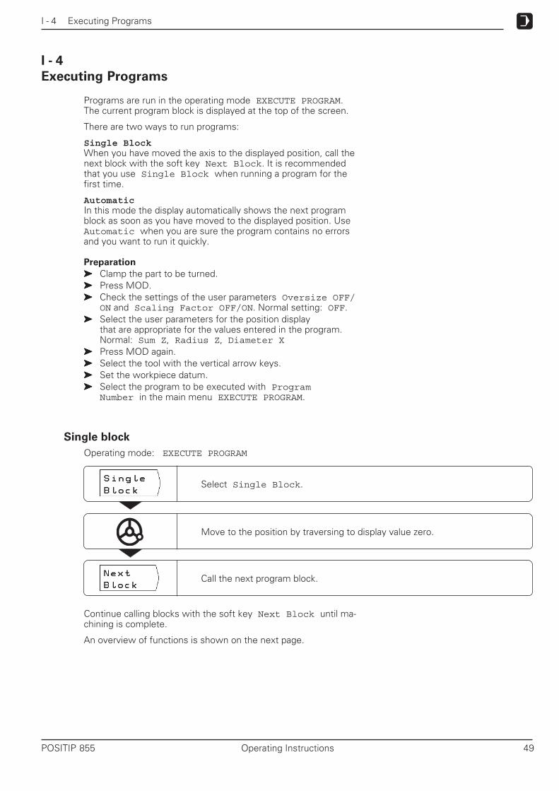
Executing Programs
Programs are run in the operating mode EXECUTE PROGRAM.The current program block is displayed at the top of the screen.
There are two ways to run programs:
Single BlockWhen you have moved the axis to the displayed position, call thenext block with the soft key Next Block. It is recommendedthat you use Single Block when running a program for thefirst time.
AutomaticIn this mode the display automatically shows the next programblock as soon as you have moved to the displayed position. UseAutomatic when you are sure the program contains no errorsand you want to run it quickly.
Preparation
➤➤➤➤➤ Clamp the part to be turned.➤➤➤➤➤ Press MOD.➤➤➤➤➤ Check the settings of the user parameters Oversize OFF/
ON and Scaling Factor OFF/ON. Normal setting: OFF.➤➤➤➤➤ Select the user parameters for the position display
that are appropriate for the values entered in the program.Normal: Sum Z, Radius Z, Diameter X
➤➤➤➤➤ Press MOD again.➤➤➤➤➤ Select the tool with the vertical arrow keys.➤➤➤➤➤ Set the workpiece datum.➤➤➤➤➤ Select the program to be executed with Program
Number in the main menu EXECUTE PROGRAM.
Single block
Operating mode: EXECUTE PROGRAM
I - 4
Select Single Block.
Move to the position by traversing to display value zero.
Call the next program block.
Continue calling blocks with the soft key Next Block until ma-chining is complete.
An overview of functions is shown on the next page.
I - 4 Executing Programs
50 Operating Instructions POSITIP 855
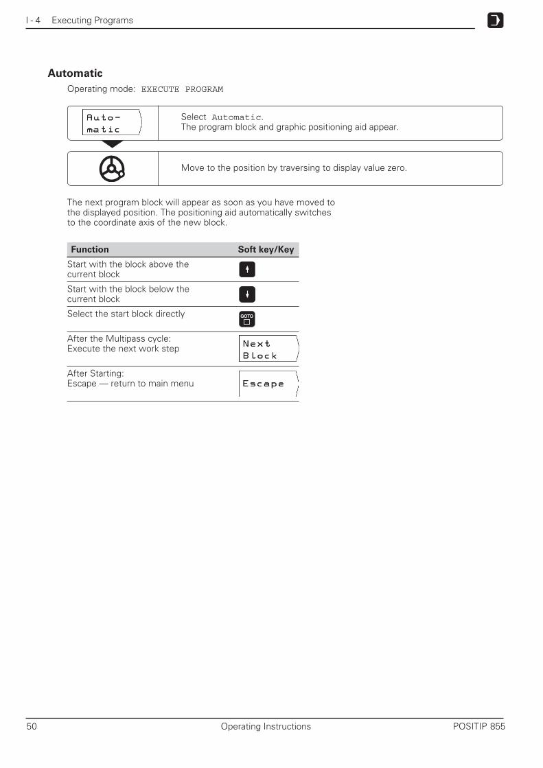
Automatic
Operating mode: EXECUTE PROGRAM
Move to the position by traversing to display value zero.
The next program block will appear as soon as you have moved tothe displayed position. The positioning aid automatically switchesto the coordinate axis of the new block.
Function Soft key/Key
Start with the block above thecurrent block
Start with the block below thecurrent block
Select the start block directly
After the Multipass cycle:Execute the next work step
After Starting:Escape — return to main menu
GOTO
Select Automatic.The program block and graphic positioning aid appear.
I - 5 INFO: Pocket Calculator, Stopwatch, Taper Calculator
POSITIP 855 Operating Instructions 51
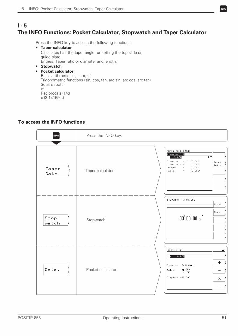
The INFO Functions: Pocket Calculator, Stopwatch and Taper Calculator
Press the INFO key to access the following functions:• Taper calculator
Calculates half the taper angle for setting the top slide orguide plate.Entries: Taper ratio or diameter and length.
• Stopwatch
• Pocket calculatorBasic arithmetic (+ , – , ×, ÷ )Trigonometric functions (sin, cos, tan, arc sin, arc cos, arc tan)Square rootsx2
Reciprocals (1/x)π (3.14159...)
To access the INFO functions
Press the INFO key.
Stopwatch
Pocket calculator
INFO
Taper calculator
I - 5
INFO

I - 5 INFO: Pocket Calculator, Stopwatch, Taper Calculator
52 Operating Instructions POSITIP 855
INFO
Fig. 27: Calculating the taper angle from thetaper diameters and length
Function Soft key/Key
Switchover for calculation from thetaper ratio
Switchover for calculation from thediameter and the length
Confirm entry
Go to the next-higher input line
Go to the next-lower input line
Switch over the input field for thetaper ratio
Taper calculator: half the taper angle for top slide or guide plate
Use the taper calculator to calculate half the taper angle.A graphic display is shown along with the result.
As soon as you conclude an entry with ENT, you are promptedfor the next entry.
Entry values
From the taper ratio, calculation of the:• Radius of the taper• Length of the taper
From both diameters and the length, calculation of the:• Starting diameter• End diameter• Length of the taper
ENT
Fig. 26: Calculating the taper angle from thetaper ratio

I - 5 INFO: Pocket Calculator, Stopwatch, Taper Calculator
POSITIP 855 Operating Instructions 53
INFO
Stopwatch
The stopwatch shows the hours (h), minutes (‘), seconds (‘’) andhundredths of a second. The stopwatch continues to run evenwhen you leave INFO. When the power is interrupted (switch-off),POSITIP resets the stopwatch to zero.
Pocket calculator
The pocket calculator functions are spread over three soft keyrows :• Basic arithmetic (first soft key row)• Trigonometry (second row)• Square root, x2, 1/x, π (third row)
Use the paging keys to go from one soft key row to the next.POSITIP always shows an example entry — you don't have topress the HELP key.
Transferring the calculated value
The calculated value remains in the input line even after you leavethe calculator. This allows you to transfer the calculated value di-rectly into a program as a nominal position — without having tore-enter it.
Entry logic
For calculations with two operands (addition, subtraction, etc.):➤➤➤➤➤ Key in the first value.➤➤➤➤➤ Press ENT.➤ Key in the second value.➤➤➤➤➤ Press the soft key for the desired operation.
POSITIP displays the result of the operation in the input line.
For calculations with one operand (sine, reciprocal, etc.):➤➤➤➤➤ Key in the value.➤➤➤➤➤ Press the soft key for the desired operation.
POSITIP displays the result of the operation in the input line.
Example: See the next page.
Function Soft key
Reset the stopwatch to zero and starttiming
Stop timing

I - 5 INFO: Pocket Calculator, Stopwatch, Taper Calculator
54 Operating Instructions POSITIP 855
Pocket calculator functions
INFO
Example: (3 ××××× 4 + 14) ÷ (2 ××××× 6 + 1) = 2
3 ENTKey-in the first value in the first parenthesis: 3; confirm entry.The display shows +3.000.
Key-in the second value in the first parenthesis: 4andcombine the second value with the first value: ×.
The display now shows +12.000.
Key-in the third value in the first parenthesis: 14andcombine the third value with the displayed value 12.000: +.
The display now shows +26.000.
Key-in the first value in the second parenthesis: 2; confirm entry.This automatically closes the first parenthesis.The display shows +2.000.
1 4
4
2 ENT
Key-in the second value in the second parenthesis: 6andcombine the second value with the first value: ×.
The display now shows +12.000.
Key-in the third value in the second parenthesis: 1andcombine the third value with the displayed value 12.000: +.
The display now shows +13.000.
Close the second parenthesis and simultaneouslycombine with the first parenthetical expression: ÷.The display now shows the result: +2.000.
6
1

I - 6 User Parameters: The MOD Function
POSITIP 855 Operating Instructions 55
I - 6
X
Z
1
2
MOD
User Parameters: The MOD Function
User parameters are operating parameters which you canchange without having to enter a code number.The machine builder decides which operating parameters are avail-able to you as user parameters as well as how the user param-eters are arranged in the soft keys.
The functions of user parameters are described in Chapter II - 2.
To access the user parameter menu
➤➤➤➤➤ Press MOD.The user parameters appear on the screen.
➤➤➤➤➤ Go to the soft key row with the desired user parameter.➤➤➤➤➤ Press the soft key for the desired user parameter.
To leave the user parameter menu
➤➤➤➤➤ Press MOD.
Scaling factors
The user parameter Scaling Factor enables you to increaseor decrease the size of workpieces. POSITIP divides the displayedvalue by the scaling factor you entered.
Scaling factors change the workpiece size symmetrically about thedatum. The workpiece datum should therefore be located at anedge when you are working with scaling factors.
Input range: 0.1 to 9.999 999
To activate scaling factors
➤➤➤➤➤ Switch the user parameter Scaling Factor OFF/ONto ON.
To deactivate scaling factors
➤➤➤➤➤ Switch the user parameter Scaling Factor OFF/ONto OFF.
Please turn to the next page for instructions on entering scalingfactors.
Fig. 28: The user parameters on the POSITIPscreen
Fig. 29: Original workpieceAfter enlargement with scalingfactor
1
2

I - 6 User Parameters: The MOD Function
56 Operating Instructions POSITIP 855
MOD
Entering user parameters
Choosing settings
Some user parameter settings are chosen directly with soft keys.You simply switch from one setting to the other.
Example: Radius/diameter display (X axis)
➤➤➤➤➤ Press MOD.The MOD main menu now contains either the soft keyDia. X or Radius X.
➤➤➤➤➤ Press the displayed soft key.The soft key changes to the other setting, for example fromDia. X to Radius X.
➤➤➤➤➤ Press MOD again.This ends the MOD function.The new setting in now in effect.
Entering values
Some user parameters require that you enter a value or select asetting from a number of possible settings. When you press thesoft key, a menu for the parameter is displayed.
Example: Scaling factor for the Z axis
➤➤➤➤➤ Press MOD.➤➤➤➤➤ Press the soft key Scaling Factor Z.
POSITIP now displays an input screen for the scaling factor.
➤➤➤➤➤ Enter a scaling factor, for example 0.75.➤➤➤➤➤ Press ENT.
If you want this scaling factor to apply to all coordinate axes,press the soft key Set All.The MOD menu appears again.
➤➤➤➤➤ Press MOD again.This ends the MOD function.The scaling factor is now in effect.

Tech
nic
al
Info
rmati
on
IIPart II: Technical Information
II - 1 Installation and Electrical Connection ..................................... 59
Items supplied .................................................................................................. 59Installation ........................................................................................................ 59Connecting the encoders ................................................................................. 60Initial switch-on ................................................................................................ 61
II - 2 Operating Parameters ............................................................... 62
Accessing the operating parameters ................................................................ 62Transferring operating parameters over the data interface .............................. 63User parameters .............................................................................................. 64List of operating parameters ............................................................................ 65
II - 3 Encoders and Measured Value Display ................................... 68
Adapting the encoders ..................................................................................... 68Setting the display step with linear encoders .................................................. 70Setting the measured value display ................................................................. 72Axis error compensation .................................................................................. 73
II - 4 Data Interface............................................................................. 75
II - 5 Measured Value Output............................................................ 77
Starting measured value output ....................................................................... 77Operating parameters for measured value output ........................................... 78Example of character output at the data interface ........................................... 79
II - 6 Switching Inputs and Outputs ................................................. 80
II - 7 Specifications............................................................................. 83
II - 8 Dimensions ................................................................................ 84
Front view ........................................................................................................ 84Top view .......................................................................................................... 84Rear view ......................................................................................................... 84Tilting base ....................................................................................................... 85
Subject Index...................................................................................... 86
II - 1 Installation and Electrical Connection
POSITIP 855 Technical Information 59
Installation and Electrical Connection
Items supplied
• POSITIP 855 Display Unit• Power connector• User's Manual
Installation
M4 screws are required for securing POSITIP to a support or a tilt-ing base from HEIDENHAIN (Id.-Nr. 281 619 01). See Chapter II - 8for the hole dimensions.
Electrical connection
Power connection
POSITIP requires AC voltage between 100 V and 240 V (48 Hz to62 Hz). No voltage adjustment is required.
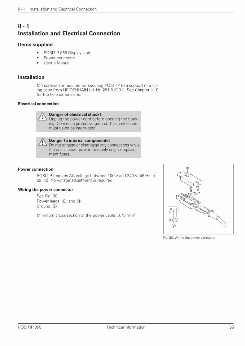
Wiring the power connector
See Fig. 30Power leads: andGround:
Minimum cross-section of the power cable: 0.75 mm2
II - 1
Fig. 30: Wiring the power connector
Danger of electrical shock!Unplug the power cord before opening the hous-ing. Connect a protective ground. This connectionmust never be interrupted.
Danger to internal components!Do not engage or disengage any connections whilethe unit is under power. Use only original replace-ment fuses.
L N

II - 1 Installation and Electrical Connection
60 Technical Information POSITIP 855
Grounding
X4
Connecting the encoders
POSITIP can be used with HEIDENHAIN linear encoders that pro-vide sinusoidal output signals. The encoder inputs on the rear panelare designated X1, X2, X3 and X4.
The connecting cable length may not exceed 30 m (100 ft).
Danger to internal components!Do not engage or disengage any connections whilethe unit is under power.
Pin layout for encoder inputs
Pin Assignment
1 0°+
2 0°–
3 +5 V (UP)
4 0 V (UN)
5 90°+
6 90°–
7 Reference mark signal RI+
8 Reference mark signal RI–
9 Internal shield
Housing External shield
2
3
45
7
1
96
8
Fig. 31: The ground screw on the rear panel
Noise immunity can be increased by connecting theground screw on the rear panel to the central groundof the machine. Minimum cross-section of theconnecting wire: 6 mm2.
Fig. 32: Flange socket on POSITIP for encodersignal input
II - 1 Installation and Electrical Connection
POSITIP 855 Technical Information 61
Interfaces X1, X2, X3 and X4 comply with the recom-mendations in VDE 0160, 5.88 for separation from linepower.
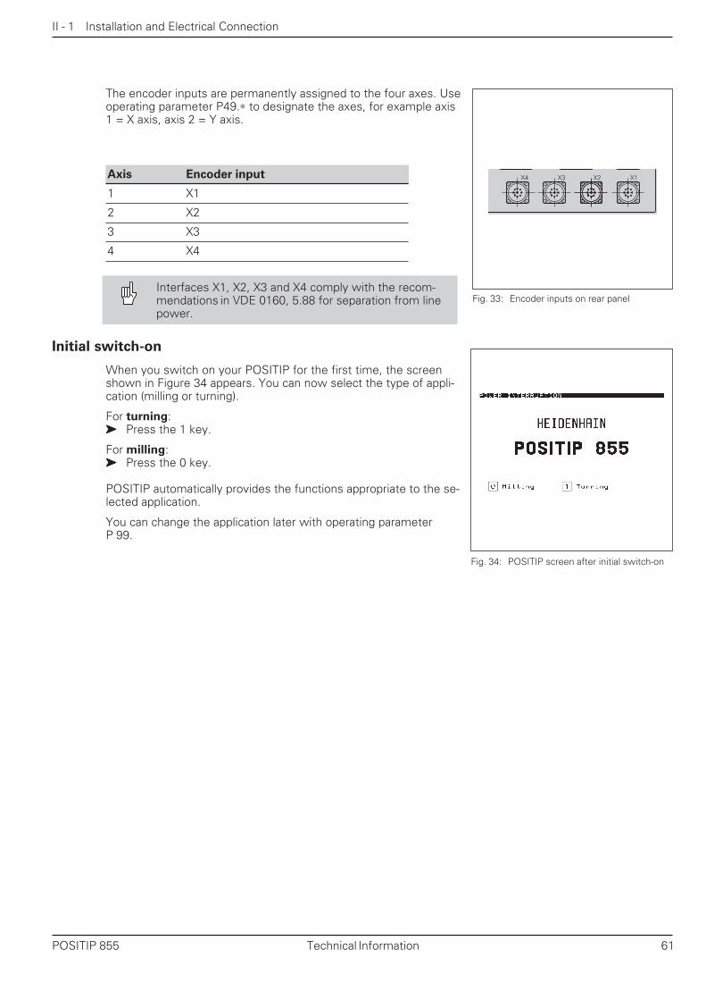
The encoder inputs are permanently assigned to the four axes. Useoperating parameter P49.∗ to designate the axes, for example axis1 = X axis, axis 2 = Y axis.
X3 X2 X1X4
Fig. 33: Encoder inputs on rear panel
Fig. 34: POSITIP screen after initial switch-on
Axis Encoder input
1 X1
2 X2
3 X3
4 X4
Initial switch-on
When you switch on your POSITIP for the first time, the screenshown in Figure 34 appears. You can now select the type of appli-cation (milling or turning).
For turning:➤➤➤➤➤ Press the 1 key.
For milling:➤➤➤➤➤ Press the 0 key.
POSITIP automatically provides the functions appropriate to the se-lected application.
You can change the application later with operating parameterP 99.

II - 2 Operating Parameters
62 Technical Information POSITIP 855
Operating Parameters
Operating parameters adapt the POSITIP to the machine. They areidentified with the letter P, a three-digit number and a name.
Axis-specific operating parameters
Some parameters require separate entries for each axis. Such pa-rameters are identified in the following descriptions with a star (∗∗∗∗∗).Example: Operating parameter for the counting direction: P30.∗∗∗∗∗For this parameter you enter the counting direction separately foreach axis in parameters P30.1, P30.2, P30.3 and P30.4.
Factory settings
The factory settings for the operating parameters in the overviewon the next pages are set in bold italics.
Numerical input, dialog input
The current setting of an operating parameter is shown in plain lan-guage under the parameter designation in the on-screen operatingparameter list. In addition, each parameter setting has a number inthe input line at the top. These numbers are transferred when youread out the operating parameters over the data interface.
To access the operating parameters
➤➤➤➤➤ Press MOD.➤➤➤➤➤ Go to the soft key row containing Code Number (soft key
with the key symbol)➤➤➤➤➤ Press the soft key Code Number➤➤➤➤➤ Enter the code number 95148.➤➤➤➤➤ Confirm your entry by pressing the ENT key➤➤➤➤➤ Display the operating parameters one after the other with the
vertical arrow keys; or
➤➤➤➤➤ Go directly to an operating parameter:Press GOTO, enter the parameter number and confirm withENT.
To change parameter settings
Operating parameter settings can be changed by selecting the newsetting or entering a numerical value.➤➤➤➤➤ Select a new setting: Press the horizontal arrow key.
or
➤➤➤➤➤ Enter a numerical value directly and confirm your entry withENT.
The horizontal arrow key has no function with parameters whichonly allow direct numerical entry.
II - 2
Fig. 35: Example of operating parameters

II - 2 Operating Parameters
POSITIP 855 Technical Information 63
Transferring operating parameters over the data interface
You can save the operating parameters on the FE 401 B floppydisk unit or a PC and read them into the POSITIP again wheneverrequired. For further information on the data interface and datatransfer, see Chapter II - 4.
Preparation
➤➤➤➤➤ Access the operating parameters as described above.➤➤➤➤➤ Go to the second soft key row.
To read out parameters
➤➤➤➤➤ Enter the program number under which you wish to save theoperating parameters.
➤➤➤➤➤ Press the soft key Param. Output.POSITIP reads out all operating parameters.
To download parameters
➤➤➤➤➤ Enter the program number under which the operatingparameters are stored on the diskette.
➤➤➤➤➤ Press the soft key Param. Input.POSITIP replaces all operating parameter settings inits memory with those on the diskette.
Fig. 36: Screen for transfer of operating param-eters

II - 2 Operating Parameters
64 Technical Information POSITIP 855
User parameters
The machine manufacturer has defined certain operating param-eters as user parameters. You can change the settings of userparameters without having to enter a code number (see OperatingInstructions section, Chapter I - 6).
Position of user parameters in the menu
In operating parameters P100 to P120, the machine manufacturerdefines how the user parameters are arranged in the soft keydisplays.
Field 15 is reserved for the soft key Code Number
If a parameter is assigned to field number 0, it will not appear inthe user parameter menu.
Operating User parameter Standardparameter designation * field ✍✍✍✍✍
P 100 mm / inch (P 1) 4 ........
P 101.1 Radius / diameter 1 (P 3.1) 1
P 101.3 Radius / diameter 3 (P 3.3) 0 ........
P 102.1 Separate / sum 1 (P 5.1) 0 ........
P 102.3 Separate / sum 3 (P 5.3) 2 ........
P 104 Scaling factor On / Off (P 11) 8 ........
P 105.1 Scaling factor 1 (P 12.1) 6 ........
P 105.3 Scaling factor 3 (P 12.3) 7 ........
P 106 Oversize On / Off (P 14) 13 ........
P 107.1 Oversize 1 (P 15.1) 11 ........
P 107.3 Oversize 3 (P 15.3) 12 ........
P 112 RS-232 baud rate (P 50) 0 ........
P 113 RS-232 blank lines (P 51) 0 ........
P 120 Tool table 5 ........
* The corresponding operating parameters are indicated inparentheses.
11 6 1
12 7 2
13 8 3
14 9 4
15 10 5
Fig. 37: Field numbering for user parameters

II - 2 Operating Parameters
POSITIP 855 Technical Information 65
✍✍✍✍✍List of operating parameters
Parameter Page Function and Numericalallowed entries entry *
P 1 mm/inch 72 Dimensions in millimeters: mm • 0 P 1 ..............16 Dimensions in inches: inch 1
P 3.1 Radius/diameter 1 72 Radius display 0 P 3.1 ...........P 3.3 Radius/diameter 3 17 Diameter display 1 P 3.3 ...........
P 5.1 Separate/sum 1 72 Separate value display 0 P 5.1 ...........P 5.3 Separate/sum 3 17 Sum display 1 P 5.3 ...........
P 11 Scaling factor OFF/ON 55 Scaling factor inactive: OFF 0 P 11 ............Scaling factor active: ON 1
P 12.1 Scaling factor 1 55 Scaling factor P 12.1 .........P 12.3 Scaling factor 3 0.1 to 9.999 999 1.0 P 12.3 .........
P 14 Oversize OFF/ON 22 Oversize inactive: OFF 0 P 14 ............Oversize active: ON 1
P 15.1 Oversize 1 22 Amount of oversize P 15.1 .........P 15.3 Oversize 3 – 199.999 to + 199.999 [mm] 0.0 P 15.3 .........
P 23 Display freeze 78 Ignore signal: Off 0 P 23 ............Influence position display by signal Stop display: Concrnt 1for measured value output Freeze display: Frozen 2
P 30.1 Counting direction 1 69 Positive counting direction 0 P 30.1 .........P 30.2 Counting direction 2 with positive traverse direction P 30.2 .........P 30.3 Counting direction 3 Negative counting direction 1 P 30.3 .........P 30.4 Counting direction 4 with positive traverse direction P 30.4 .........
P 31.1 Signal period 1 70 Signal period of linear encoder 20 P 31.1 .........P 31.2 Signal period 2 (see operating instructions for P 31.2 .........P 31.3 Signal period 3 encoder) P 31.3 .........P 31.4 Signal period 4 P 31.4 .........
P 32.1 Linear subdivision 1 70 Linear subdivision of the 20 P 32.1 .........P 32.2 Linear subdivision 2 encoder signals P 32.2 .........P 32.3 Linear subdivision 3 P 32.3 .........P 32.4 Linear subdivision 4 P 32.4 .........
P 40.1 Error compensation 1 73 No axis error compensation: OFF 0 P 40.1 .........P 40.2 Error compensation 2 Linear axis error comp.: Linear 1 P 40.2 .........P 40.3 Error compensation 3 Non-linear axis error 2 P 40.3 .........P 40.4 Error compensation 4 compensation: Non-linear P 40.4 .........
P 41.1 Linear compensation 1 73 Amount of a linear axis error +0.0 P 41.1 .........P 41.2 Linear compensation 2 compensation [ppm] P 41.2 .........P 41.3 Linear compensation 3 P 41.3 .........P 41.4 Linear compensation 4 P 41.4 .........
P 43.1 Distance coding 1 68 No distance coding: None 0 P 43.1 .........P 43.2 Distance coding 2 500 × GP, 1000 × GP 500, 1000 P 43.2 .........P 43.3 Distance coding 3 2000 × GP, 5000 × GP 2000, 5000 P 43.3 .........P 43.4 Distance coding 4 P 43.4 .........
P 44.1 Reference mark 1 68 Evaluate reference marks: Yes 0 P 44.1 .........P 44.2 Reference mark 2 Do not evaluate: No 1 P 44.2 .........P 44.3 Reference mark 3 P 44.3 .........P 44.4 Reference mark 4 P 44.4 .........
* Standard factory settings are in bold italics

II - 2 Operating Parameters
66 Technical Information POSITIP 855
Parameter Page Function and Numericalallowed entries entry*
P45.1 Encoder monitoring 1 69 Monitoring off 0 P45.1 ..........P45.2 Encoder monitoring 2 Monitoring on 1 P45.2 ..........P45.3 Encoder monitoring 3 P45.3 ..........P45.4 Encoder monitoring 4 P45.4 ..........
P48.1 Axis definition 1 69 Do not display axis: off 0 P48.1 ..........P48.2 Axis definition 2 Display axis: on 1 P48.2 ..........P48.3 Axis definition 3 P48.3 ..........P48.4 Axis definition 4 P48.4 ..........
P49.1 Axis designation 1 72 Axis is coordinate axis A 65 2) P49.1 ..........P49.3 Axis designation 3 Axis is coordinate axis B 66 2) P49.3 ..........
Axis is coordinate axis C 67 2) ...................Axis is coordinate axis U 85 2) ...................Axis is coordinate axis V 86 2) ...................Axis is coordinate axis W 87 2) ...................Axis is coordinate axis X 88 2) ...................Axis is coordinate axis Y 89 2) ...................Axis is coordinate axis Z 90 2) ...................
P50 RS-232-C baud rate 76 Speed of data transfer P50 .............150 [Baud] ≤ P 50 ≤ 38 400 [baud] 9 600
P51 RS-232-C blank lines 78 Number of line feeds after output P51 .............of measured value [0 to 99] 1
P60.0 Switching output 0 81 Off 0 P60.0 ..........P60.1 Switching output 2 Assigned to axis 1 1 P60.1 ..........P60.2 Switching output 2 Assigned to axis 2 2 P60.2 ..........P60.3 Switching output 3 Assigned to axis 3 3 P60.3 ..........P60.4 Switching output 4 Assigned to axis 4 4 P60.4 ..........P60.5 Switching output 5 P60.5 ..........P60.6 Switching output 6 P60.6 ..........P60.7 Switching output 7 P60.7 ..........
P61.0 Switching range 0 81 Enter the switching range 0.0 P61.0 ..........P61.1 Switching range 2 symmetrically to zero in [mm] P61.1 ..........P61.2 Switching range 2 P61.2 ..........P61.3 Switching range 3 P61.3 ..........P61.4 Switching range 4 P61.4 ..........P61.5 Switching range 5 P61.5 ..........P61.6 Switching range 6 P61.6 ..........P61.7 Switching range 7 P61.7 ..........
P69 Switching signal 78 Mode 1 (Signal delay 80 ms) 0 P69 .............Mode 2 (Signal delay 5 ms) 1
P81.1 16/40µA switchover 1 68 Encoder signal 16 µA 0 P81.1 ..........P81.2 16/40µA switchover 2 Encoder signal 40 µA 1 P81.2 ..........P81.3 16/40µA switchover 3 P81.3 ..........P81.4 16/40µA switchover 4 P81.4 ..........
1) Standard factory settings are in bold italics
2) Factory setting for P 49.∗: P49.1 = 88; P 49.3 = 90
List of operating parameters
✍✍✍✍✍

II - 2 Operating Parameters
POSITIP 855 Technical Information 67
List of operating parameters
Parameter Page Function and Numerallowed entries entry 1)
P 83 Sleep delay – Screen saver starts after P 83 ............Screen saver (periodically 5 to 98 [min] 15reverses the screen image) No screen saver 99
P 90 Graphic positioning aid – Positive to the right: Normal 0 P 90 ............Direction of traverse in positioning Positive to the left: Inverse 1aid when traversing to zero
P 91 Distance-to-go – Graphic positioning aid: Graphic 0 P 91 ............In DISTANCE-TO-GO mode, Tool position: Actual value 1display either graphic positioningaid or actual position of tool
P 92 Feed rate display – Do not display feed rate: Off 0 P 92 ............Display of feed rate F in status Display feed rate: On 1line at bottom of screen
P 98 Dialog language – First language, e.g. German 0 P 98 ............Second language, e.g. English 1
P 99 Counter application – Lathe: Turning 1 P 99 ............Milling machine: Milling 0
*) Standard factory settings are in bold italics.Operating parameters P 100 to P 120 are listed on page 64
✍✍✍✍✍

II - 3 Encoders and Measured Value Display
68 Technical Information POSITIP 855
II - 3
Encoders and Measured Value Display
This chapter describes all operating parameters which you mustset for the encoders and measured value display. Most entries canbe found in the operating instructions for your encoder. ChapterII - 2 contains a list of operating parameters in which you canrecord your entries.
• Adapting the encoder
- Encoder output signals 16 µA or 40 µA- Reference marks on the encoder:
distance-coded or one reference mark- Deactivation of reference mark evaluation- Definition of the coordinate axes- Counting direction of the encoder signals- Encoder monitoring- Linear axis error compensation
• Selection of display step
• Setting the measured value display
- Designations of the coordinate axes- Unit of measurement- Radius/diameter display- Separate value/sum display
Adapting the encoders
Encoder output signal: P 81.*
Encoder with 16 µA output signal: P 81.* = 0Encoder with 40 µA output signal: P 81.* = 1
The position feedback encoders on the machine may have one referencemark or several distance-coded reference marks.
Reference marks on the encoder: P 43.*
One reference mark (None): P 43.* = 0Distance-coded reference marks (500 x GP): P 43.* = 500Distance-coded reference marks (1000 x GP): P 43.* = 1000Distance-coded reference marks (2000 x GP): P 43.* = 2000Distance-coded reference marks (5000 x GP): P 43.* = 5000
Reference mark evaluation can be deactivated separately for each axis.Note that the datum points for those axes are then no longer stored innonvolatile memory.
Reference mark evaluation: P 44.*
Evaluate reference mark(s) (Yes): P 44.* = 0
Do not evaluate reference mark(s) (No): P 44.* = 1

II - 3 Encoders and Measured Value Display
POSITIP 855 Technical Information 69
Definition of the coordinate axes: P 48.*
Do not display axis off: P 48.* = 0Display axis on: P 48.* = 1
You can define separately for each axis whether the encoder sig-nals are counted positive or negative in positive direction oftraverse.
Counting direction of the encoder signals: P 30.*
Positive counting direction: P 30.* = 0Negative counting direction: P 30.* = 1
Monitoring of encoder:• cable and connectors• traversing speed• measuring signals
Encoder monitoring: P 45.*
Encoder monitoring off: P 45.* = 0Encoder monitoring on: P 45.* = 1
Adapting the encoders

II - 3 Encoders and Measured Value Display
70 Technical Information POSITIP 855
Setting the display step with linear encoders
With linear encoders, the display step depends on the• signal period of the encoder (P31.∗) and the• linear subdivision (P32.∗).
Both parameters are entered separately for each axis. The linearsubdivision can range from 0.1 to 128 depending on the signalperiod of your encoder.
For linear measurement using nut/ballscrew arrangements androtary encoders, calculate the signal period as follows:
Signal period [µm] = Drivescrew pitch [mm] x 1000 Line count
Display step, signal period and linear subdivision for linear encoders
Signal period [µm] 2 4 10 20 40 100 200 12 800
Display step [mm] [inch] Linear subdivision
0.000 02 0.000 001 100 – – – – – – –0.000 05 0.000 002 40 80 – – – – – –
0.000 1 0.000 005 20 40 100 – – – – –0.000 2 0.000 01 10 20 50 100 – – – –0.000 5 0.000 02 4 8 20 40 80 – – –
0.001 0.000 05 2 4 10 20 40 100 – –0.002 0.000 1 1 2 5 10 20 50 100 –0.005 0.000 2 0.4 0.8 2 4 8 20 40 –
0.01 0.000 5 0.2 0.4 1 2 4 10 20 –0.02 0.001 – – 0.5 1 2 5 10 –0.05 0.002 – – 0.2 0.4 0.8 2 4 –
0.1 0.005 – – 0.1 0.2 0.4 1 2 1280.2 0.01 – – – – – – – 64

II - 3 Encoders and Measured Value Display
POSITIP 855 Technical Information 71
Setting the display step with linear encoders
Example settings for HEIDENHAIN linear encoders
Encoder P31.∗∗∗∗∗ P43.∗∗∗∗∗ P32.∗∗∗∗∗Signal Reference Display step Linearperiod marks mm inch subdiv.
LIP 40x 2 0 0.001 0.000 05 20.000 5 0.000 02 40.000 2 0.000 01 100.000 1 0.000 005 200.000 05 0.000 002 400.000 02 0.000 001 100
LIP 101A 4 0 0.001 0.000 05 4LIP 101R 0.000 5 0.000 02 8
0.000 2 0.000 01 200.000 1 0.000 005 400.000 05 0.000 002 80
LIF 101. LF 401 4 0 0.001 0.000 05 40.000 5 0.000 02 80.000 2 0.000 01 200.000 1 0.000 005 40
LID xxx 10 0 0.001 0.000 05 10LID xxxC 2 000 0.000 5 0.000 02 20
LS 103. LS 103C 0 0.000 2 0.000 01 50LS 405. LS 405C or 0.000 1 0.000 005 100ULS/10 1 000
LS 303. LS 303C 20 0 0.01 0.000 05 2LS 603. LS 603C or 0.005 0.000 02 4
1 000
LS 106. LS 106C 20 0 0.01 0.000 5 2LS 406. LS 406C or 0.005 0.000 2 4LS 706. LS 706C 1 000 0.002 0.000 1 10ULS/20 0.001 0.000 05 20
0.000 5 0.000 02 40
LIDA 190 40 0 0.002 0.000 1 20LB 101 0.001 0.000 05 40
0.000 5 0.000 02 80
LIDA 2xx 100 0 0.01 0.000 5 10LB 3xx 0.005 0.000 2 20
0.002 0.000 1 500.001 0.000 05 100
LIM 102 12 800 0 0.2 0.01 640.1 0.005 128

II - 3 Encoders and Measured Value Display
72 Technical Information POSITIP 855
Setting the measured value display
Designation of the coordinate axes: P49.∗∗∗∗∗Axis is coordinate axis A: P 49.* = 65Axis is coordinate axis B: P 49.* = 66Axis is coordinate axis C: P 49.* = 67Axis is coordinate axis X: P 49.* = 85Axis is coordinate axis Y: P 49.* = 86Axis is coordinate axis Z: P 49.* = 87Axis is coordinate axis U: P 49.* = 88Axis is coordinate axis V: P 49.* = 89Axis is coordinate axis W: P 49.* = 90
Unit of measurement: P 1 (user parameter)
Display dimensions in millimeters (mm): P 1 = 0Display dimensions in inches (inch): P 1 = 1
In the diameter display mode, the symbol for the diameter (Ø) appears nextto the display value, and the display value doubles.
Radius/diameter display: P 3.* (user parameter)
Display position values as radius: P 3.* = 0Display position values as diameter: P 3.* = 1
In the separate value display mode, POSITIP displays the positions of thesaddle and top slide separately. In the sum display mode, the position val-ues of the two axes are added together.
Separate value/sum display: P 5.* (user parameter)
Separate value display mode: P 5.* = 0Sum display mode: P 5.* = 1

II - 3 Encoders and Measured Value Display
POSITIP 855 Technical Information 73
Linear and non-linear errors can occur on the axes of a machine, e.g. errorsin drivescrew pitch, or errors caused by axis sag and tilt. These errors canbe detected with a comparator system such as the VM 101 fromHEIDENHAIN. POSITIP can compensate these errors. You can activate er-ror axis compensation using parameter P40.
Axis error compensation: P40.∗∗∗∗∗Axis error compensation (Off): P40.* = 0Linear axis error compensation (Linear): P40.* = 1Non-linear axis error compensation (Non-linear): P40.* = 2
Linear axis error compensation
A factor that you enter in operating parameter P41.* compensates for thiserror.
Example calculation of compensation factor kDisplayed distance: LD = 620 mmActual distance as determinedwith comparator system: LA = 619.876 mmDifference: ∆l = LA – LD = –0.124 mm ∆l = –124 µmCompensation factor k = ∆l / LD = – 200 µm / m = – 200 ppm
Linear axis error compensation: P 41.*
Compensation factor k P 41.* = 0–99 999 [ppm] < P 41.* < 99 999 [ppm]
Axis error compensation

II - 3 Encoders and Measured Value Display
74 Technical Information POSITIP 855
Non-linear axis error compensation
Working with non-linear axis error compensationTo activate the non-linear axis error compensation you have to:➤➤➤➤➤ Activate the function using working parameter P40 .➤➤➤➤➤ Enter the compensation values in the table.➤➤➤➤➤ Traverse the reference points every time you turn the machine
on .
Selection of the operating mode COMPENSATION VALUETABLEIn the operating mode COMPENSATION VALUE TABLE enter thecompensation values for non-linear axis error compensation as fol-lows:➤➤➤➤➤ Press the "MOD" key.➤➤➤➤➤ Select "Code Number" soft key.➤➤➤➤➤ Enter code number 105 296 and confirm with ENT.
The POSITIP 855 automatically switches the position display toREF when the compensation value table is selected (the datum forthe display is the scale reference point).
The functions are in two soft-key rows and can be selected usingthe "paging" keys.Row 1: Enter the compensation value using the keyboard.Row 2: Read in or output the compensation value table using datainterface.You can enter compensation values at 64 compensation points foreach axis — as a function of the positions in the axis causing theerror.
Input dataSelect the individual input fields with the arrow keys and enter:➤➤➤➤➤ The axis which is to be corrected under "faulty axis?". Press axis soft key.➤➤➤➤➤ The axis which is causing the error under "axis causing error?"
Press axis soft key.➤➤➤➤➤ The datum for the axis causing the error under "datum."➤➤➤➤➤ The distance between the compensation points for the axis
causing the error under "compensation point distance?" as anexponent to the base 2 :
e.g. 14 = 214 = 16 384 µm.➤➤➤➤➤ Compensation values: compensation point 0 is preassigned the
value 0.000 and cannot be changed.
Delete the tableYou can delete the table values as follows:➤➤➤➤➤ Select the table to be deleted under "faulty axis?" and press
the axis soft key.➤➤➤➤➤ Press "delete table."

II - 4 Data Interface
POSITIP 855 Technical Information 75
X 3 1 ( R S - 2 3 2 - C / V . 2 4 )
13 10 7 4 1
14182125
Data Interface
The POSITIP's data interface allows you to save programs andoperating parameters on diskette, or print out or save coordinates.Chapter I - 3 describes how to transfer programs, and ChapterII - 2 describes how to transfer operating parameters.
This chapter covers what you need to know about setting up thedata interface:• Pin layout of the data interface• Signal levels• Wiring of the connecting cable and connectors• Baud rate (data transfer speed)• Data format
Connections
The RS-232-C/V.24 serial port is located on the POSITIP's rearpanel. The following devices can be connected to this port:
• HEIDENHAIN FE 401 floppy disk unit• Printer with serial data interface• Personal computer with serial data interface
The HEIDENHAIN FE 401 floppy disk unit is immedi-ately ready for operation at the data interface.
Interface X31 complies with the recommendations inVDE 0160, 5.88 for separation from line power.
Pin layout on the POSITIP data interface
Pin Assignment
1 CHASSIS GND – Chassis ground
2 TXD – Transmitted data
3 RXD – Received data
4 RTS – Request to send
5 CTS – Clear to send
6 DSR – Data set ready
7 SIGNAL GND – Signal ground
20 DTR – Data terminal ready
8 to 19 Do not assign
21 to 25 Do not assign
Signal levels
Signal Signal level Signal level1 = active 0 = not active
TXD, RXD – 3 V to – 15 V + 3 V to + 15 V
RTS, CTS + 3 V to + 15 V – 3 V to – 15 VDSR, DTR
II - 4
Fig. 38: Pin layout of RS-232-C/V.24 datainterface

II - 4 Data Interface
76 Technical Information POSITIP 855
Start bit
7 data bits
Parity bit
2 stop bits
Wiring the connecting cable
The wiring of the connecting cable depends on the device beingconnected (see technical documentation for external device).
Full wiring Simplified wiring
11GND
2
3
4
5
6
20
7
TXD
RXD
RTS
CTS
DSRGNDSIGNAL
DTR
CHASSIS
2
3
4
5
6
20
7
PT 855
GND
TXD
RXD
RTS
CTS
DSRGNDSIGNAL
DTR
CHASSIS 1GND
2
3
4
5
6
20
7
TXD
RXD
RTS
CTS
DSRGNDSIGNAL
DTR
CHASSIS 1 GND
2
3
4
5
6
20
7
TXD
RXD
RTS
CTS
DSRGNDSIGNAL
DTR
CHASSIS
PT 855
Setting the baud rate: P 50
The baud rate set on the POSITIP must be the same as that of theexternal device. The external device must be capable of processingthe selected baud rate. The baud rate for the data interface on thePOSITIP is set with an operating parameter. The machine manufac-turer can also make this parameter available as a user parameter(see I - 6).
Settings for the baud rateP 50 = 110, 150, 300, 600, 1200, 2400,
4800, 9600, 19 200, 38 400 [baud]
The baud rate for data transfer between POSITIP andthe FE 401 floppy disk unit is always 9600.
Data format
Data is transferred in the following sequence:1. Start bit2. Seven data bits3. Parity bit (even parity)4. Two stop bits
Interrupting data transfer
There are two ways to interrupt data transfer from the external de-vice and restart it:
➤➤➤➤➤ Start/Stop over input RXDDC3 = XOFF = CTRL S: interrupt data transferDC1 = XON = CTRL Q: resume data transfer
➤➤➤➤➤ Start/Stop over control line CTS
When the stop signal CTS or DC3 has been received,POSITIP sends up to two further characters.
S D D D D D D D P S S
Fig. 41: Data transfer format
Fig. 39: Diagram for full wiring Fig. 40: Diagram for simplified wiring

II - 5 Measured Value Output
POSITIP 855 Technical Information 77
II - 5
Measured Value Output
POSITIP can output measured values over the data interface.
Starting measured value output
There are two ways to start measured value output:• Transmit control character to the data interface• Send signal to switching input
The delay between the latch signal and measured value output de-pends on the selected signal.
Transit time of encoder signals
After approximately 4 µs the encoder signals are present in abuffer that is interrogated by the internal latch signal. The meas-ured value that is output is therefore the value that existed approxi-mately 4 µs prior to the internal latch.
Starting measured value output over external switching input
You can start measured value output over the switching input atthe D-sub connection EXT by sending a pulse or by make contact.
Contact at pin 9: make contact against 0 VPulse at pin 8: pulse duration te ≥ 1.2 µs
The contact or pulse can also be sent over a TTL logic device(such as SN 74 LS XX):UH ≥ 3.9 V (UMAX = 15 V)UL ≤ 0.9 V with IL ≤ 6 mA
E X T
P I N 9
P I N 1( 0 V )
P I N 8
P I N 1( 0 V )
te
E X T
t1
t3t2
tD
te
TXD
te: Minimum duration, pulsete ≥ 1.2 ms
te: Minimum duration, contactte ≥ 7 ms
t1: Delay between pulse and internal latcht1 ≤ 0.8 µs
t1: Delay between contact and internal latcht1 ≤ 4.5 ms
t2: Delay between internal latch and measured value outputt2 ≤ 30 ms
t3: Delay between end of data output and next latch overexternal switching inputt3 ≥ 0 ms
tD: Duration of measured value output
The duration of measured value output (tD) depends on:• The selected baud rate (BR)• The number of axes (M)• The number of blank lines (L)
tD = [s]BR
187 × M + L × 11
Fig. 43: Time diagram for measured value out-put over external switching input
Fig. 42: Signal by make contact against 0 V

II - 5 Measured Value Output
78 Technical Information POSITIP 855
Fig. 44: Time diagram for measured value out-put with Ctrl B
Starting measured value output
C t r l B C t r l B
t1
t3t2
tD
RXD
TXD
Starting measured value output with Ctrl B
t1: Delay between Ctrl B command and internal latcht1 ≤ 0.5 ms
t2: Delay between internal latch and measured value outputt2 ≤ 30 ms
t3: Time between end of data output and next latch with Ctrl Bt3 ≥ 0 ms
tD: Duration of measured value output
The duration of measured value output (tD) depends on• The selected baud rate (BR),• The number of axes (M)• The number of blank lines (L)
tD = [s]
Operating parameters for measured value output
The following operating parameters will influence measuredvalue output — regardless of how you start it.
Number of blank lines after each measured value: P51
Number of blank lines after measured value: P51 = 0 to 99
You can also use the signal for measured value output toinfluence position display.
Screen display during measured value output: P23
The display is not stopped during measuredvalue output (Off): P23 = 0The display is stopped during measured value outputand remains stopped as long as the switching input“output measured value” is active (Concrnt): P23 = 1The display is stopped but is updated by everymeasured value output (Frozen): P23 = 2
BR
187 × M + L × 11

II - 5 Measured Value Output
POSITIP 855 Technical Information 79
31 4 5 6
Example of character output at the data interface
The numbers stand for1 Coordinate axis
2 Blank space (separate value mode), S (sum mode) orO (top slide)
3 Equality sign
4 +/– sign
5 Carriage return
6 Line feed
Example: Linear axis with sum display mode Z = + 5841.2907 mm
Z S = + 5 8 4 1 . 2 9 0 7 R <CR> <LF>
2 to 7 placesDecimal point1 to 6 placesUnit: blank space for mm, " for inchesActual value display:
R for radius, D for diameterDistance-to-go display:
r for radius, d for diameter
2

II - 6 Switching Inputs and Outputs
80 Technical Information POSITIP 855
II - 6
Switching Inputs and Outputs
Switching signals at the D-sub connection EXT allow you to• reset the actual value display of a coordinate axis to zero• control motor cutoff• start measured value output (see Chapter II - 5)
Interface X41 (EXT) complies with the recom-mendations in VDE 0160, 5.88 for separationfrom line power.
The outputs for the switching ranges are me-tallically isolated from the device electronics bymeans of optocouplers.
Danger to internal components!Voltage from external circuitry must conformto the recommendations in VDE 0100, Part 410for low-voltage electrical separation.
Connect inductive loads such as relays only witha quenching diode. Shield against electromag-netic fields. Connect with a shielded cable withthe shield extended to the connector housing.
Pin layout of D-sub connection EXT (X41)
Pin Assignment
10 0 V for switching range
23, 24, 25 24 V DC for switching range
11 POSITIP ready for operation
14 Display value outside of switching range 0
15 Display value outside of switching range 1
16 Display value outside of switching range 2
17 Display value outside of switching range 3
18 Display value outside of switching range 4
19 Display value outside of switching range 5
20 Display value outside of switching range 6
21 Display value outside of switching range 7
1 0 V (internal)
2 Reset axis 1 to zero
3 Reset axis 2 to zero
4 Reset axis 3 to zero
5 Reset axis 4 to zero
8 Pulse: output measured value
9 Contact: output measured value
6, 7, 12, Do not use 13, 22
Ou
tpu
tsIn
pu
ts
1 62 73 854 9
14 15 16 17 18 19 20 21
10 11 12 13
22 23 24 25
Fig. 45: The D-sub connection EXT

II - 6 Switching Inputs and Outputs
POSITIP 855 Technical Information 81
Reset actual value display to zero
You can reset the actual value display of each axis to zero throughone of the inputs at pin 2 to pin 5 (see previous page).
Minimum pulse duration for zero reset: tmin ≥ 100 ms
Zero reset signal: make contact against 0 V orinput pulse over TTL logic device (such as SN 74 LS XX):UH ≥ 3.9 V (UMAX = 15 V)UL ≤ 0.9 V with IL ≤ 6 mA
Using the switching signals
If you wish to use the switching signals, you must supply POSITIPwith 24 V DC at the D-sub connection EXT (pins 23 to 25; 0 V topin 10). Pins 14 to 21 will then be supplied with 24 V as long as thedisplay value is not within a switching range.
These pins are then assigned to the axes with operating parameterP60.x. As soon as a display value is within the switching range, thevoltage to the corresponding pin will be cut off. Define the switch-ing range in operating parameter P61.x symmetrically around zero.
If the location of the datum point changes, move theswitching ranges correspondingly.
Axis assignment: P60.x
No axis assigned (Off): P60.x = 0Assigned to axis 1: P60.x = 1Assigned to axis 2: P60.x = 2Assigned to axis 3: P60.x = 3Assigned to axis 4: P60.x = 4
Define the switching range: P 61.x
0 to 99 999.999 [mm] symmetrically around zero P61.x
Permissible load at switching outputs
IMAX = 100 mADC resistanceConnect inductive load only with quenching diode.
Accuracy of switching ranges and switching delay: P 69
You can select the switching delay and the accuracy with whichthe switching outputs are switched.
You can choose between• Accuracy = display step; switching delay = 80 ms
This is mode 1: P 69 = 0
• Accuracy = Grating period GP of encoder
Switching delay = 5 ms. This is mode 2: P 69 =1
Danger to internal components!Connect inductive loads only with a quench-ing diode parallel to the inductance.
128
P60.2P61.2P61.2X:
0
– +
Fig. 46: The switching ranges are symmetricalaround zero

II - 6 Switching Inputs and Outputs
82 Technical Information POSITIP 855
"POSITIP ready for operation" Output
In order to use the “POSITIP is ready for operation” signal youmust supply 24 V DC to pins 23, 24 and 25 (0 V to pin 10). Duringnormal operation, pin 11 of D-sub connection EXT has 24 V.
If an error occurs which impairs the functioning of POSITIP (suchas a hardware or checksum error), POSITIP switches the output atpin 11 off.
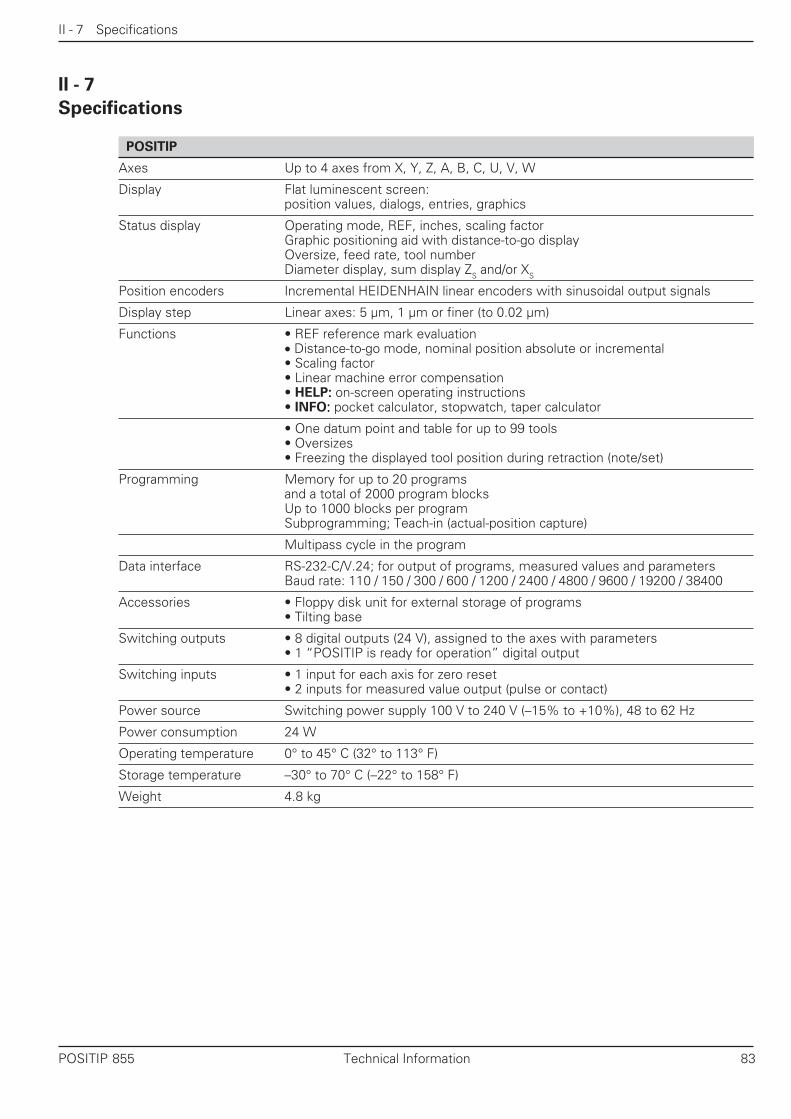
II - 7 Specifications
POSITIP 855 Technical Information 83
Specifications
POSITIP
Axes Up to 4 axes from X, Y, Z, A, B, C, U, V, W
Display Flat luminescent screen:position values, dialogs, entries, graphics
Status display Operating mode, REF, inches, scaling factorGraphic positioning aid with distance-to-go displayOversize, feed rate, tool numberDiameter display, sum display ZS and/or XS
Position encoders Incremental HEIDENHAIN linear encoders with sinusoidal output signals
Display step Linear axes: 5 µm, 1 µm or finer (to 0.02 µm)
Functions • REF reference mark evaluation• Distance-to-go mode, nominal position absolute or incremental• Scaling factor• Linear machine error compensation• HELP::::: on-screen operating instructions• INFO::::: pocket calculator, stopwatch, taper calculator
• One datum point and table for up to 99 tools• Oversizes• Freezing the displayed tool position during retraction (note/set)
Programming Memory for up to 20 programsand a total of 2000 program blocksUp to 1000 blocks per programSubprogramming; Teach-in (actual-position capture)
Multipass cycle in the program
Data interface RS-232-C/V.24; for output of programs, measured values and parametersBaud rate: 110 / 150 / 300 / 600 / 1200 / 2400 / 4800 / 9600 / 19200 / 38400
Accessories • Floppy disk unit for external storage of programs• Tilting base
Switching outputs • 8 digital outputs (24 V), assigned to the axes with parameters• 1 “POSITIP is ready for operation” digital output
Switching inputs • 1 input for each axis for zero reset• 2 inputs for measured value output (pulse or contact)
Power source Switching power supply 100 V to 240 V (–15% to +10%), 48 to 62 Hz
Power consumption 24 W
Operating temperature 0° to 45° C (32° to 113° F)
Storage temperature –30° to 70° C (–22° to 158° F)
Weight 4.8 kg
II - 7

II - 8 Dimensions
84 Technical Information POSITIP 855
II - 8
Dimensions
HEIDENHAIN
X
35+
0.5
1.38
+.0
2"83
±0.
23.
27±
.008
"
128+
25.
04+
.08"
30 1.2" 0
22±
0.2
.87±
.008
"
278±
0.2
10.9
4±.0
08"
300±
0.2
11.8
1±.0
08"
923.622" M4
43.3
1.70
4"
75 2.95
"
X3 X2 X1
X10X31(V.24 RS-232-C)X41(EXT)
X4
X

II - 8 Dimensions
POSITIP 855 Technical Information 85
Tilting base
2409.45"
562.
205"
210 ± 0.28.268 ± .008"
15.6"
8.32"
4.5.18"
120
+ 0
.54.
73 +
.02"
38 ± 0.51.5 ± .02"
20°
923.622"
4.5.18"

Subject Index
86 POSITIP 855
E
Editing existing programs ..... 44Electrical connection ............ 59Encoders ....................... 60, 68
connecting ....................... 60counting direction ............ 69linear encoders ................ 70monitoring ....................... 69output signal .................... 68signal transit time ............ 77
ENT key ................................ 62Entry logic ............................ 53Error compensation .............. 65Error messages .................... 16Executing programs ............. 49Extern ................................... 46
F
Feed rate display .................. 67Freezing positions ................ 18Functions
HELP ............................... 14MOD ............................... 14INFO ................................ 14programmable .......... 27, 29
G
Graphic positioning aid ......... 67Grounding ............................. 60
H
HELP .................................... 15
I
Inchesselecting .......................... 16
Incremental dimensions ......... 9INFO ..................................... 51INFO key .............................. 51Installation ............................ 59Internal latch ......................... 78
K
Keyboard ................................ 2
L
Labels ................................... 39label call ........................... 39label number .................... 40label numbers .................. 42setting ............................. 40setting (inserting) ............. 42
LBL ...................................... 39Linear compensation ............ 65Linear encoders .................... 70Linear subdivision .......... 65, 70
M
Measured value display . 68, 72Measured value output . 77, 78
Millimetersselecting .......................... 16
MOD .................................... 55Monitoring
encoder ......................... 66encoder signals ............. 69
Multipass cycle .................... 36
N
Nesting program sections .... 39Nominal positions
changing after transfer .... 35Non-linear compensation ...... 65
O
Operand ............................... 53Operating instructions
(on-screen) ...................... 15Operating modes .................. 14Operating parameters .......... 62
transferring ...................... 63Output signals
of encoder ....................... 68Oversizes ....................... 22, 65
P
Pin layoutD-sub connection EXT ..... 80data interface .................. 75encoder inputs ................. 60
Pocket calculator ........... 51, 53Position display mode .......... 17Position encoders ................. 11Positioning aid ...................... 22Positions
displaying......................... 22moving to ........................ 22transferring ...................... 33
POSITIP ready for operation . 82Power connection ................ 59Power connector, wiring ...... 59Program
reading out ...................... 47Program blocks
changing .......................... 44current block ................... 30deleting..................... 30, 45entering ........................... 30inserting new................... 30selecting .......................... 30
Program directory ................. 28Program number
changing .......................... 44Program section repeats ...... 39
calling and entering ......... 42Program sections
nesting ............................ 39Programming ........................ 27Programming steps .............. 31Programs
archiving .......................... 46deleting............................ 28
Subject Index
A
Actual postition ..................... 11Automatic ...................... 49, 50Axis assignment ................... 81Axis definition ....................... 66Axis designation ................... 66Axis error compensation ...... 73
B
Baud rate ....................... 66, 76Blank lines ............................ 78Blinking error messages ....... 16
C
Calculated valuetransferring ...................... 53
Calculating functions ............ 53Calculator ...................... 51, 53CALL LBL ............................. 39Chain dimensions ................... 9Character output ................... 79Code number ........................ 62Connection
electrical .......................... 59encoders ......................... 60
Coordinate axisdefining............................ 69designation ...................... 72
Coordinatesabsolute ............................. 9incremental .................. 9, 22
Correcting program errors .... 44Correction factor ................... 73Counter applications ............. 67Counting direction ......... 65, 69Cutoff signals ....................... 81CYCL .................................... 36
D
D-sub connection ................. 80Data format .......................... 76Data interface ................ 63, 75
connections ..................... 75setup ............................... 75signal levels ..................... 75wiring .............................. 76
Data transferinterrupting ...................... 76
Datum setting................... 8, 18Deleting program blocks....... 45Deleting programs ................ 28Dialog language .................... 67Diameter display ............ 17, 72
symbol for ................... 2, 17Display freeze ....................... 65Display step .......................... 70Distance coding .................... 65Distance-to-go ......... 14, 22, 67Downloading parameters ..... 63

Subject Index
POSITIP 855 87
editing ............................. 44executing ......................... 49interrupting (STOP) .......... 38new ................................. 28program directory ............ 28selecting .......................... 28transferring ...................... 46
R
Radius display................ 17, 72REF ...................................... 13Reference marks ..... 11, 65, 68
crossing over ................... 13distance-coded ................ 11evaluation of .................... 68not crossing over ............. 13not evaluating .................. 68
Reference point .................... 11
S
Scaling factor ................. 55, 65symbol ............................ 2
Separate value display .......... 17Settings
choosing .......................... 56Shoulder
turning ............................. 24Signal period .................. 65, 70Signal transit time................. 77Single block .......................... 49Sleep delay ........................... 67Soft key row ......................... 15Software version .................... 3STOP .................................... 38Stopwatch ..................... 51, 53Storing positions ................... 18Subprograms ................. 39, 40
calling .............................. 41Sum display .......................... 17Switch-on ............................. 13Switching delay .................... 81Switching inputs ............ 77, 80Switching outputs .......... 66, 80
cutoff range ..................... 81cutoff signals ................... 81
Switching signal ................... 66Switchover 16 µm / 40µm .... 66
T
Taper angle ........................... 52Taper calculator ............. 51, 52Teach-In .................. 27, 33, 35Tilting base ........................... 59Tool data
entering .................... 18, 21in program ....................... 32
Tools
calling .............................. 32tool axis ........................... 32TOOL CALL ..................... 32tool number ..................... 32tool table ......................... 32
Transferring programs .......... 46Traversing to zero ................. 22
U
Undersize ............................. 22Unit of measurement ........... 72
selecting .......................... 16User parameters ........... 55, 64
entering ........................... 56menu ............................... 55
W
Workpiecechanging size of .............. 55
Workpiece datum ................. 19Workpiece position
absolute ............................. 9incremental ........................ 9
Z
Zero point (of workpiece) ..... 19Zero reset ............................. 81

Subject Index
88 POSITIP 855
NOTES

����������������� �������������� ��� ������������������������� ������� ��� ��� �� ������� ��� ��� �� ��� ����� ��� �!� ��� ��
� ������� ��� ��� �� �����"�#"� $%&���' ( ��� ��� �� ����������� ��� ��� �� ��������� �����' (!� ��� ��
���)���***�� ��� ��
278 738-21 · SW03 · 3 · 8/2000 · F+W · Printed in Germany · Subject to change without notice