USER´S MANUAL HAKI Loading Tower
24
USER´S MANUAL © HAKI AB 2018 HAKI Loading Tower
Transcript of USER´S MANUAL HAKI Loading Tower
USER´S MANUAL
© HAKI AB 2018
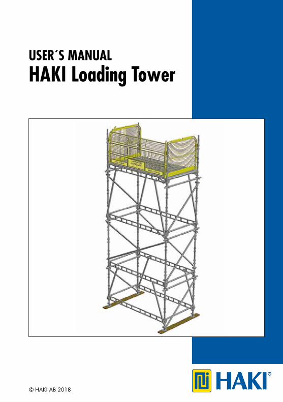
HAKI Loading Tower
2
© Copyright HAKI AB, 2018The reproduct ion of text and pictures/illustrat ions without HAKI’s permission is prohibited.
Important informationHAKI’s product liability and user´s manuals apply only to scaffolds that are entirely composed of components that have been made and supplied by HAKI.
HAKI’s scaffold systems must not be erected using components of makes other than HAKI or be connected to scaffolds of makes other than HAKI. In such cases, a special study of load-bearing capacity must be carried out. However, HAKI has no objection to the customary addition of scaffold tubes and approved couplers to the scaffold.
Adding components from different suppliers may invalidate the insurance cover.
This user´s manual is based on a minimum of 2 competent erectors.
This user´s manual is to be used in conjunct ion with HAKI training courses.
A user’s manual should be provided to the user together with the scaffolding.
HAKI reserves the right to make technical modifications on a continual basis.
The latest versions of HAKI user’s manuals can be downloaded from our website, www.HAKI.com.
For scaffold structures that are not covered by this user´s manual, please contact HAKI’s technical department.
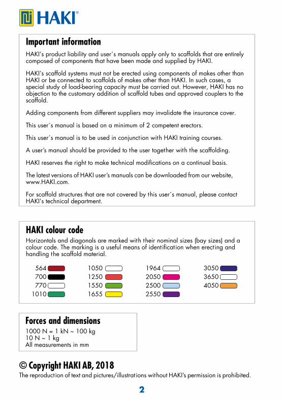
Forces and dimensions 1000 N = 1 kN ~ 100 kg 10 N ~ 1 kgAll measurements in mm
HAKI colour codeHorizontals and diagonals are marked with their nominal sizes (bay sizes) and a colour code. The marking is a useful means of ident ificat ion when erect ing and handling the scaffold material.
564 1050 1964 3050 700 1250 2050 3650 770 1550 2500 4050 1010 1655 2550

3
The HAKI Loading Tower is designed for loads of 15kN/m2 or 7.5 tonnes UDL and caters for impact loading caused by fork lift or crane. The Tower has a plan dimension of 3050mm x 1655mm and lift heights of 1000, 1500 or 2000mm can be achieved. Always ensure the ground is fully prepared to support the Loading Tower and that the correct size of sole pads is used.
The Loading Tower is made from pre-fabricated components. All components are hot-dip galvanized. The HAKI Loading Tower consists of HAKI Universal base jacks, standards, beams, steel decks and diagonal braces. Other components that are designedspecifically for Loading Towers include knee braces, plan braces, side panels and gates.The Loading Tower will always be built progressively and as a separate construct ion.
BASIC INFORMATION
HAKI Loading Tower
General
All components with the exception of locking catches, locking pins, etc. comepermanent ly marked with the HAKI logo and the last two figures of the year ofmanufacture ( S18).All load bearing components are marked for full traceability.
Marking
IMPORTANT
ENGAGE LOCKING CATCHES AS EACHCOMPONENT IS FIXED

4
BASIC INFORMATION
Gate
Erect ion Plat form
Single Ledger
Diagonal Brace
Standard
Diagonal Brace
Knee Brace
Ledger Beam
3050mm
1655mm
Tie tube
Side Panel
Knee Brace
Base Jack
2mLift
2mLift
1.5mLift
Typical 6m High Tower - Top Working Lift Only
Load Bearing Coupler
5
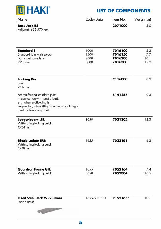
LIST OF COMPONENTSName Code/Data Item No. Weight(kg)
Base Jack BSAdjustable 55-570 mm
2071000 5.0
Standard SStandard joint with spigotPockets at same levelØ48 mm
1000150020003000
7016100701615070162007016300
5.37.7
10.115.2
Locking PinSteelØ 16 mm
For reinforcing standard jointin connect ion with tensile load,e.g. when scaffolding issuspended, when lift ing or when scaffolding is used for temporary roof.
2116000
5141257
0.2
0.3
Ledger beam LBLWith spring locking catchØ 34 mm
3050 7021302 12.3
Single Ledger ERBWith spring locking catchØ 48 mm
1655 7022161 6.3
Guardrail Frame GFLWith spring locking catch
16553050
70521647052304
7.410.5
HAKI Steel Deck W=230mmLoad class 6
1655x230x90 21521655 10.1
6
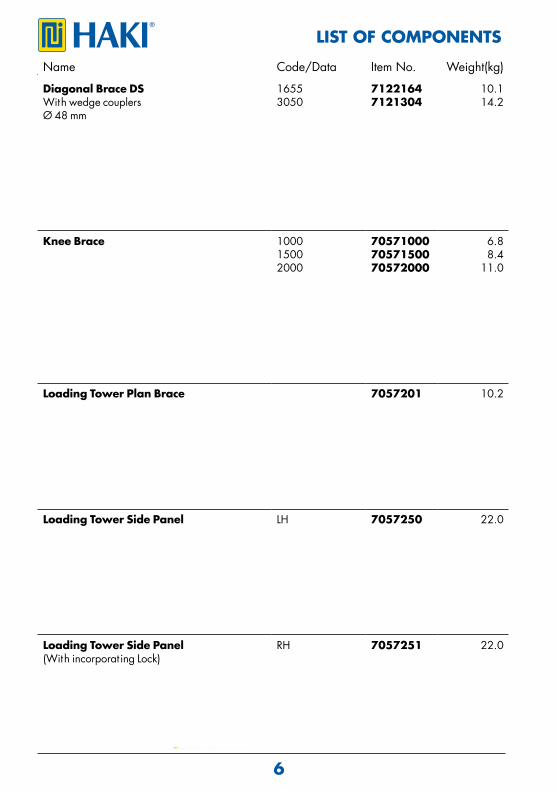
LIST OF COMPONENTSName Code/Data Item No. Weight(kg)
Diagonal Brace DSWith wedge couplersØ 48 mm
16553050
71221647121304
10.114.2
Knee Brace 100015002000
705710007057150070572000
6.88.4
11.0
Loading Tower Plan Brace 7057201 10.2
Loading Tower Side Panel LH 7057250 22.0
Loading Tower Side Panel(With incorporat ing Lock)
RH 7057251 22.0

7
LIST OF COMPONENTSName Code/Data Item No. Weight(kg)
Loading Tower Gate
Gate closed for transportat ion
7057300 34.0
Ramp 900x300 7057249 9.0
Spacer 300 300 7022030 1.5
Standard Adaptor SC 7011002 2.9
Toeboard AL 300 4161031 0.65
8
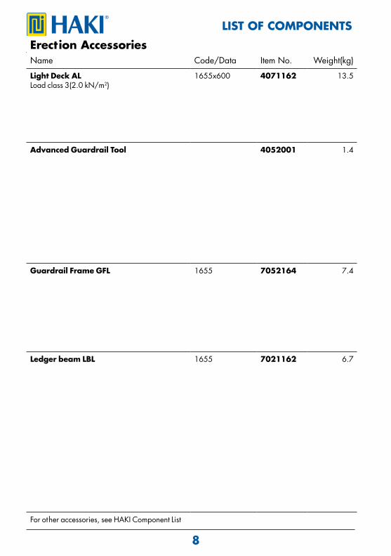
LIST OF COMPONENTSErection AccessoriesName Code/Data Item No. Weight(kg)
Light Deck ALLoad class 3(2.0 kN/m2)
1655x600 4071162 13.5
Advanced Guardrail Tool 4052001 1.4
Guardrail Frame GFL 1655 7052164 7.4
Ledger beam LBL 1655 7021162 6.7
For other accessories, see HAKI Component List
9
Informat ion on safety when erect ing and dismant ling 1. Carry out local risk assessment and method statement. 2. Make sure that all lift ing equipment to be used, e.g chain hoists, lift ing ropes, pulley blocks, etc., has been thoroughly tested and approved by an outhorised person in accordance with local regulat ions. 3. Check that tools and protect ive equipment are available at the worksite. 4. Wear appropriate personal safety equipment at all t imes, e.g safety harnesses, proper independence lifelines with suitable fixings, etc. 5. When erect ing and dismant ling a scaffold, robust temporary decking must be used as temporary platforms for the scaffolders. 6. Always make sure that the safety locking devices that prevent a plat form lift ing off have been act ivated once a platform has been installed. 7. Study all relevant instruct ions or safety direct ions from the manufacturers of the various scaffolds that are to be used. 8. Never climb up a scaffold from the outside. Always use the stairs, ladders or climbing frames that are designed to provide access to the upper decks from the inside of the scaffold. 9. lf the scaffold is to be used outdoors, erect ion or dismant ling work must be discont inued if the weather condit ions are too bad. Make sure that all loose components are properly fixed before leaving the scaffold.10. Scaffolding work must be carried out by "competent operat ives" under the supervision of a "competent person".11. Lift ing equipment must not be attached to a free-standing scaffold.12. Beware of any overhead power lines nearby.13. Always observe and comply with the regulat ions issued by the local authorit ies concerned.14. Erectors/dismant lers should always be clipped to a single ledger or ledger beam during erect ion/dismant ling. Reference should also be made to sect ion ”Personal Safety Equipment” in the Universal User manual.
10
1.
2a. 2b.
3a. 3b.
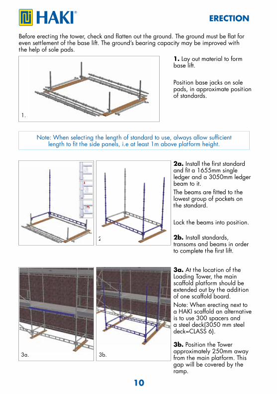
ERECTION
1. Lay out material to form base lift.
Posit ion base jacks on sole pads, in approximate posit ion of standards.
2a. Install the first standard and fit a 1655mm single ledger and a 3050mm ledger beam to it.The beams are fitted to the lowest group of pockets on the standard.
Lock the beams into posit ion.
2b. Install standards, transoms and beams in order to complete the first lift.
3a. At the location of the Loading Tower, the main scaffold platform should be extended out by the addit ion of one scaffold board.Note: When erect ing next to a HAKI scaffold an alternat ive is to use 300 spacers and a steel deck(3050 mm steel deck=CLASS 6). 3b. Posit ion the Tower approximately 250mm away from the main platform. This gap will be covered by the ramp.
Before erect ing the tower, check and flatten out the ground. The ground must be flat for even sett lement of the base lift. The ground’s bearing capacity may be improved with the help of sole pads.
Note: When select ing the length of standard to use, always allow sufficientlength to fit the side panels, i.e at least 1m above platform height.
11
4a. 4b.
5a.
6. 6.
7.
7a.
7b.
7c.
5b.
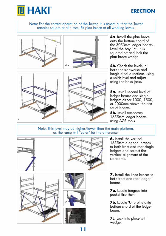
ERECTION
4a. Install the plan brace onto the bottom chord of the 3050mm ledger beams. Level the bay unt il it is squared off and lock the plan brace wedge.
4b. Check the levels in both the transverse and longitudinal direct ions using a spirit level and adjust using the base jacks.
5a. Install second level of ledger beams and single ledgers either 1000, 1500, or 2000mm above the first set of beams.5b. Install temporary 1655mm ledger beams using AGR tools.
6. Install the vert ical 1655mm diagonal braces to both front and rear single ledgers and correct the vert ical alignment of the standards.
7. Install the knee braces to both front and rear ledger beams.
7a. Locate tongues into pocket first then,
7b. Locate ‘U’ profile onto bottom chord of the ledger beam.
7c. Lock into place with wedge.
Note: For the correct operat ion of the Tower, it is essent ial that the Towerremains square at all t imes. Fit plan brace at all working levels.
Note: This level may be higher/lower than the main platform,as the ramp will ”cater” for the difference.

12
9a.
8a. 8b.
9b.
10.
10a.
10b.
ERECTION
8a. Install 1655mm steel decks over the ledger beams.
8b. Prevent uplift by closing locking catch.
9a. Reposit ion plan brace to new level.
9b. Install any T&F required to t ie the Tower to the main scaffold or ‘make up’ guardrails.
10a. Install ramp onto ledger beam and t ighten securing nut.
10b. Lower the ramp onto the scaffold board.
Note: Ramp is not used if the Loading Tower isconnected to a HAKI scaffold.
Note: You will now need to access the Tower Plat form. 11. As there will be no fall prevent ion in place, the erectors should ´Hook on´ their harnesses to the main scaffold.

13
13.
14.
12.
15.
ERECTION
12. From the Tower Plat form install the right hand (RH) side panel (with incorporat ing lock) and the left hand (LH) side panel.
Raise the gate to the Tower Plat form in the folded posit ion (eg front face of toe board facing downwards, handle facing upwards).
13. Support on side panel.
14. Feed first roller into side panel via entry.
15. Slide forward unt il the 2nd and 3rd rollers are located into track.
INSTALLATION OF GATE
IMPORTANTENGAGE ALL LOCKING CATCHES

14
16b.
17.
16a.
18.
19.
ERECTION
16a, b. Lift remainder of gate and extend towards you.
17. Slide gate forward unt il all remaining rollers are located into the side panel.
18. Lower gate into the closed posit ion.
19. The gate can only beopened from the loading plat form.
Raise locking catch.
TO OPEN THE GATE
Note: The gate can only be opened from the loading platform.
15
20a.
20b.
21.
22.
23.
ERECTION
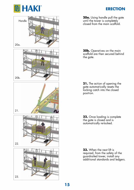
20a. Using handle pull the gate unt il the tower is completely closed from the main scaffold.
20b. Operatives on the main scaffold are then secured behind the gate.
21. The act ion of opening the gate automatically resets the locking catch into the closed posit ion.
22. Once loading is complete the gate is closed and isautomatically re-locked.
23. When the next lift is required, from the safety of the guardrailed tower, install anyaddit ional standards and ledgers.
Handle

16
24c.
24e.
24a.
25.
24d.
24f.
24b.
24g.
ERECTION
24. Remove gate (reverse of 13-18) and side panels.Store the removed components on main scaffold.Scaffolding material must NOT be thrown down from the scaffold.
25. Repeat steps 5b to 18.
Continue erect ion up to the desired height.
Use approved lift ing equipment for transport ing materials.
Whilst clipped on to the scaffold remove gate and side panels.

17
1. Do not throw or drop materials to the ground. This may damage the material or cause personal injury. The materials must be lowered down to the ground by means of ropes or slings or passed down by hand. 2. If intermediate t ies or t ie rod tubes have been installed, they must not be removed unt il the dismant ling process reaches the level in quest ion. 3. Always observe and comply with the regulat ions published by the local authorit ies concerned. 4. Dismant lers should always be clipped to a single ledger or ledger beam during dismant ling. 5. Reference should also be made to sect ion ”Information on safety when erect ing and dismant ling” on page 9 in this manual.
Informat ion on safety when dismant ling
DISMANTLING
Typical 6m High Tower - Top working lift Only
18
4.
1.
2.
3.
DISMANTLING
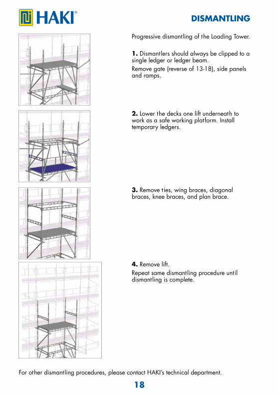
For other dismant ling procedures, please contact HAKI’s technical department.
Progressive dismant ling of the Loading Tower.
1. Dismant lers should always be clipped to a single ledger or ledger beam.Remove gate (reverse of 13-18), side panels and ramps.
2. Lower the decks one lift underneath to work as a safe working platform. Install temporary ledgers.
3. Remove t ies, wing braces, diagonal braces, knee braces, and plan brace.
4. Remove lift. Repeat same dismant ling procedure unt il dismant ling is complete.
19
A
B
C
B
C
DESIGN CONDITIONS
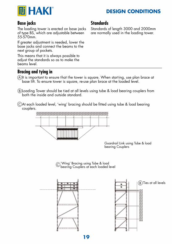
Base jacksThe loading tower is erected on base jacks of type BS, which are adjustable between 55-570mm.If greater adjustment is needed, lower the base jacks and connect the beams to the next group of pockets.This means that it is always possible to adjust the standards so as to make the beams level.
StandardsStandards of length 3000 and 2000mm are normally used in the loading tower.
Bracing and tying in It is important to ensure that the tower is square. When start ing, use plan brace at base lift. To ensure tower is square, re-use plan brace at the loaded level.
Loading Tower should be t ied at all levels using tube & load bearing couplers from both the inside and outside standard.
At each loaded level, ‘wing’ bracing should be fitted using tube & load bearing couplers.
Guardrail Link using Tube & load bearing Couplers
‘Wing’ Bracing using Tube & load bearing Couplers at each loaded level
Ties at all levels
20
Bracing and tying in
DESIGN CONDITIONS
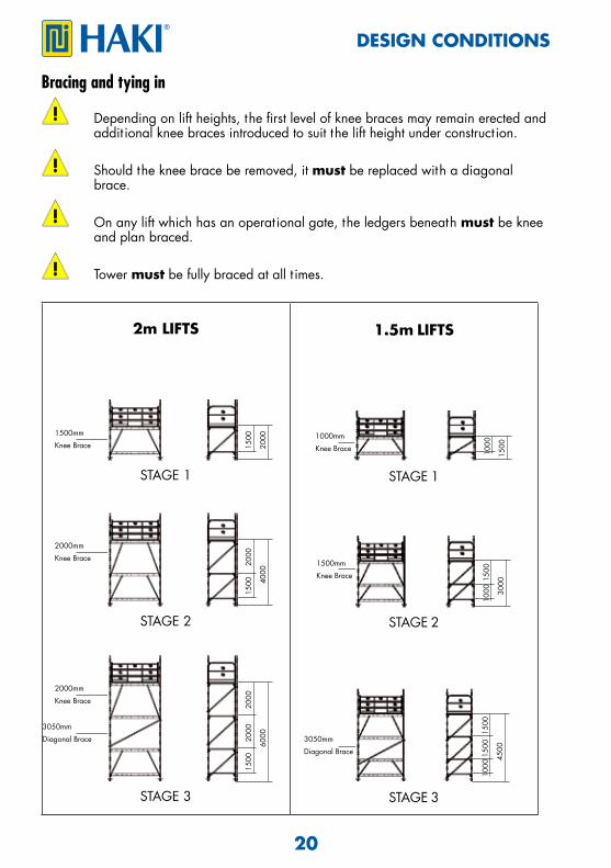
Depending on lift heights, the first level of knee braces may remain erected and addit ional knee braces introduced to suit the lift height under construct ion.
Should the knee brace be removed, it must be replaced with a diagonal brace.
On any lift which has an operat ional gate, the ledgers beneath must be knee and plan braced.
Tower must be fully braced at all t imes.
2m LIFTS
STAGE 1
STAGE 2
STAGE 3
1.5m LIFTS
STAGE 1
STAGE 2
STAGE 3
1500mm
Knee Brace 1500
2000
2000mm
Knee Brace
2000
4000
2000mm
Knee Brace
2000
6000
1500
1500
20003050mm
Diagonal Brace
1000mm
Knee Brace 1000
1500
1500mm
Knee Brace
3050mm
Diagonal Brace
1500
3000
1000
1500
4500
1500
1000

21
LOADING CONDITIONS
Maximum Tower Loading
With Knee Braces 15kN/m2 75kN UDL
Without Knee Braces 5kN/m2 25kN UDL
Maximum Tower Heights
Loading (kN/m2) 2m Lifts (m) 1.5m Lifts (m)
1@15 82 68
1@10 100 96
2@10 42 34
2@5 100 92
3@5 74 60
4@5 34 28
1@10+1@5
78 64
1@10+2@5
38 32
For condit ions outside of the above, please contact the HAKI Technical Department.

22
ALTERNATIVE ARRANGEMENTS
Gates and Plan Braces to be provided by the client.
On any lift which has an operat ional gate, the ledgers beneath must be plan braced.
Tower must be fully braced at all t imes.
6 Leg Tower Arrangements
6 Leg Tower-Maximum Tower Loading
Length (m) Width (m)
2x1.9642.5
1.9641.655
8 kN/s2
11 kN/s2
13 kN/s2
2x1.6552.5
1.9641.655
11 kN/s2
15 kN/s2
17 kN/s2
For construct ions not covered in this User´s Guide, please contact the HAKI Technical Department.
For progressive build:Standard Adaptor70110022.9 kg
WL
23
SAFE SCAFFOLDING
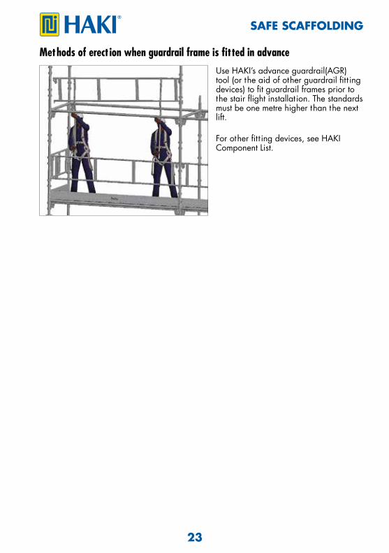
Methods of erect ion when guardrail frame is fitted in advanceUse HAKI’s advance guardrail(AGR) tool (or the aid of other guardrail fitt ing devices) to fit guardrail frames prior to the stair flight installat ion. The standards must be one metre higher than the next lift.
For other fitt ing devices, see HAKI Component List.
Health and Safety at Work Act, 1974
Experience With over 60 years experience to call on, HAKI has gained a leading reputat ion in its field. With its own R & D and manufacturing facilit ies, the company now operates throughout Europe and its equipment is in use worldwide. With all products designed and manufactured to ISO 9001:2008, and a comprehensive training and supportinfrastructure, you can rely on HAKI for support.
Training The Company´s dedicated Training Centre is equipped with the full range of HAKI products where a comprehensive choice of courses is offered. With the benefit of this training, all users of HAKI products can be assured that the equipment is being employed safely and effect ively.
Support From computerised est imating facilit ies to on site assessment and project back up, HAKI is with its customers every step of the way. Working with HAKI means far more than just proven equipment, it means working with people who understand the scaffolding industry. Whatever the project, the company is committed to ensuring every user enjoys the full benefits associated with the use of HAKI - maximising the savings, profitability, and above all, SAFETY.
HAKI equipment is designed to meet the requirements of the above Act, Sect ion 6.It is also the customer´s responsibility to comply with the requirements of this Act, part icularly to use the equipment in accordance with current codes of pract ice and in ensuring that components are in good working condit ion prior to each use.We are able to provide assistance and advice on matters relat ing to safe and proper use of HAKI equipment.
HAKI AB • SE-289 72 Sibbhult, Sweden • Tel +46 44 494 00 • [email protected] www.HAKI.com ©
HA
KI IN
T 20
18 0
4 P
0001
77