User's Guide LX Dual Stacking Arm, Tall Pole · hardware or loss of data and tells you how to avoid...
10
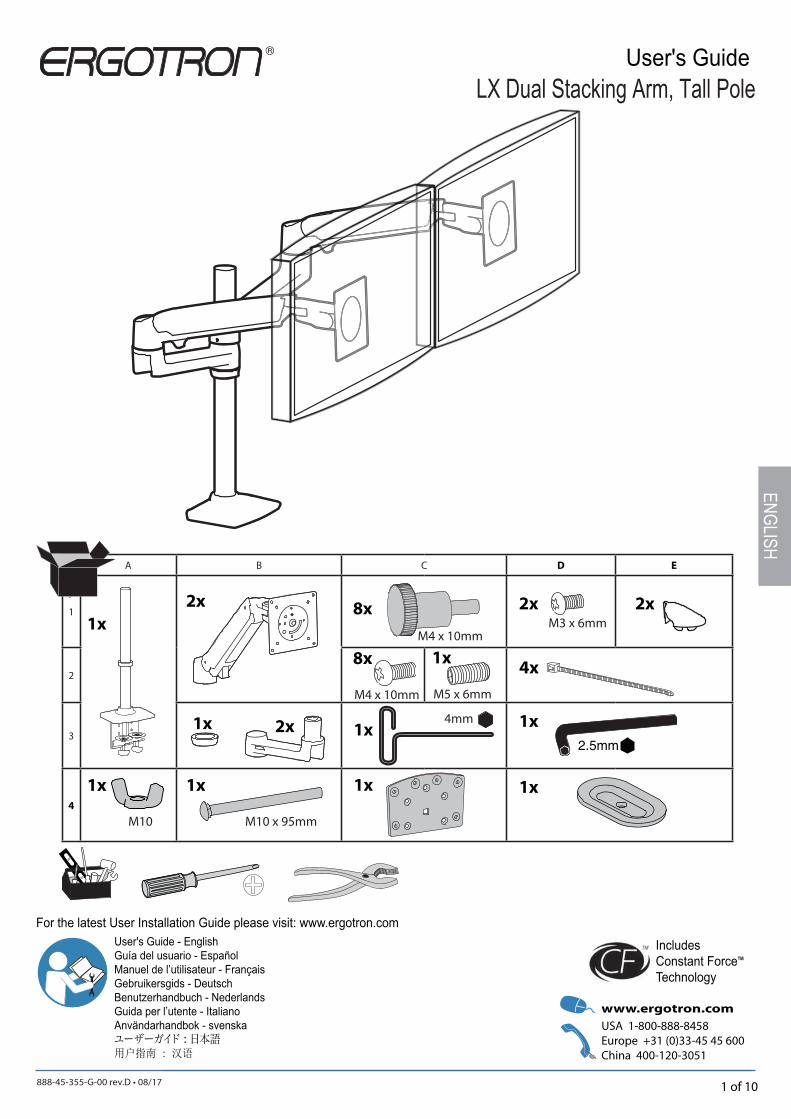
888-45-355-G-00 rev.D • 08/17 1 of 10 LX Dual Stacking Arm, Tall Pole A B C D E 1 2 3 4 M4 x 10mm 8x M4 x 10mm 8x 4mm 1x 2x M3 x 6mm 4x 2x 2x 1x 2x 1x 1x 2.5mm User's Guide - English Guía del usuario - Español Manuel de l’utilisateur - Français Gebruikersgids - Deutsch Benutzerhandbuch - Nederlands Guida per l’utente - Italiano Användarhandbok - svenska ユーザーガイド : 日本語 用户指南 : 汉语 Includes Constant Force™ Technology M5 x 6mm 1x 1x 1x 1x 1x M10 x 95mm M10 ENGLISH User's Guide For the latest User Installation Guide please visit: www.ergotron.com
Transcript of User's Guide LX Dual Stacking Arm, Tall Pole · hardware or loss of data and tells you how to avoid...
888-45-355-G-00 rev.D • 08/17 1 of 10
LX Dual Stacking Arm, Tall Pole
A B C D E
1
2
3
4
M4 x 10mm
8x
M4 x 10mm
8x
4mm1x
2xM3 x 6mm
4x
2x 2x1x
2x1x 1x
2.5mm
User's Guide - EnglishGuía del usuario - EspañolManuel de l’utilisateur - FrançaisGebruikersgids - DeutschBenutzerhandbuch - NederlandsGuida per l’utente - ItalianoAnvändarhandbok - svenskaユーザーガイド : 日本語用户指南 : 汉语
IncludesConstant Force™
Technology
M5 x 6mm
1x
1x1x 1x 1x
M10 x 95mmM10
ENGLISH
User's Guide
For the latest User Installation Guide please visit: www.ergotron.com
888-45-355-G-00 rev.D • 08/17 2 of 10
ENGL
ISH
These symbols alert users of a safety condi-tion that demands attention. All users should be able to recognize and understand the signifi cance of the following Safety Hazards if encountered on the product or within the documentation. Children who are not able to recognize and respond appropriately to Safety Alerts should not use this product with-out adult supervision!
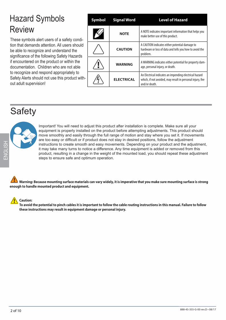
Hazard Symbols Review
Symbol Signal Word Level of Hazard
NOTEA NOTE indicates important information that helps you
make better use of this product.
CAUTION
A CAUTION indicates either potential damage to
hardware or loss of data and tells you how to avoid the
problem.
WARNINGA WARNING indicates either potential for property dam-
age, personal injury, or death.
ELECTRICAL
An Electrical indicates an impending electrical hazard
which, if not avoided, may result in personal injury, fi re
and/or death.
SafetyImportant! You will need to adjust this product after installation is complete. Make sure all your equipment is properly installed on the product before attempting adjustments. This product should move smoothly and easily through the full range of motion and stay where you set it. If movements are too easy or diffi cult or if product does not stay in desired positions, follow the adjustment instructions to create smooth and easy movements. Depending on your product and the adjustment, it may take many turns to notice a difference. Any time equipment is added or removed from this product, resulting in a change in the weight of the mounted load, you should repeat these adjustment steps to ensure safe and optimum operation.
Warning: Because mounting surface materials can vary widely, it is imperative that you make sure mounting surface is strong
enough to handle mounted product and equipment.
Caution:
To avoid the potential to pinch cables it is important to follow the cable routing instructions in this manual. Failure to follow
these instructions may result in equipment damage or personal injury.
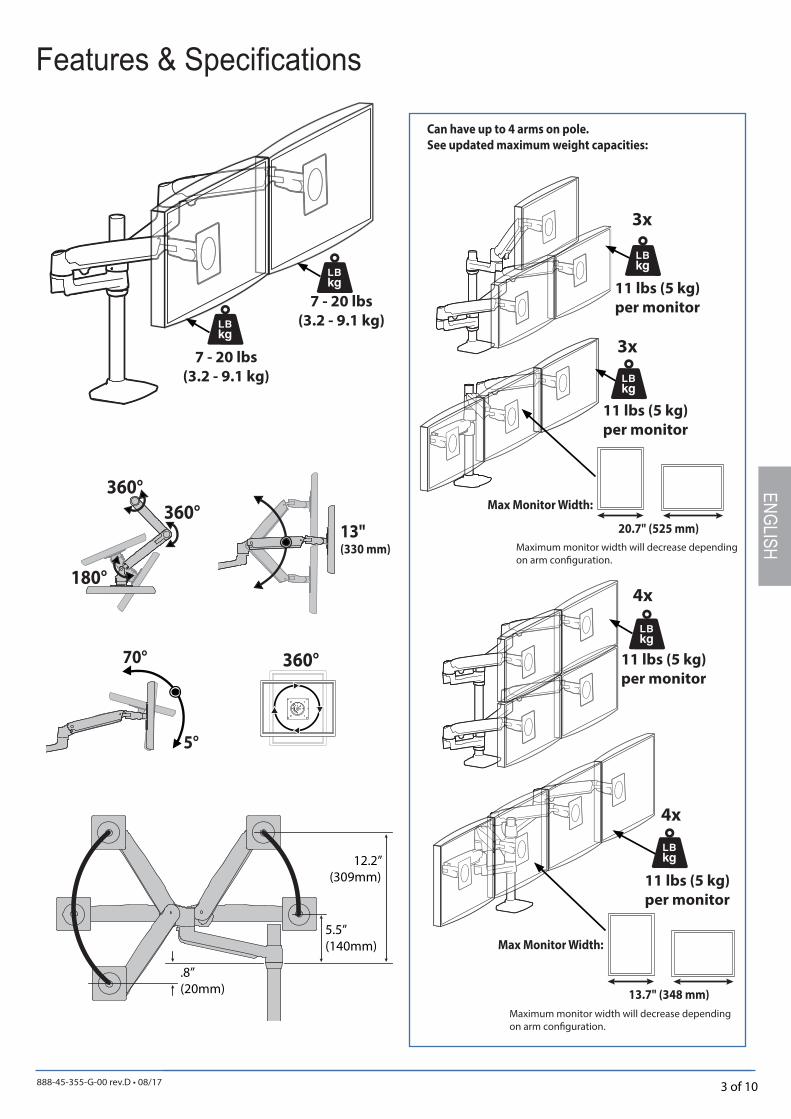
888-45-355-G-00 rev.D • 08/17 3 of 10
12.2”(309mm)
.8”(20mm)
5.5”(140mm)
5°
70°
360°
360°
360°
180°
13"(330 mm)
7 - 20 lbs
(3.2 - 9.1 kg)
7 - 20 lbs
(3.2 - 9.1 kg)
3x
4x
4x
13.7" (348 mm)
Maximum monitor width will decrease depending on arm confi guration.
3x
20.7" (525 mm)
ENGLISH
11 lbs (5 kg)
per monitor
Max Monitor Width:
Can have up to 4 arms on pole.
See updated maximum weight capacities:
Features & Specifi cations
11 lbs (5 kg)
per monitor
11 lbs (5 kg)
per monitor
11 lbs (5 kg)
per monitor
Max Monitor Width:
Maximum monitor width will decrease depending on arm confi guration.

888-45-355-G-00 rev.D • 08/17 4 of 10
< .63" (16 mm)
.5" - 1.63" (11 - 41 mm)
1.42" - 2.6" (36 - 66 mm)
4mm
1
c d
f
a b
e≥ 0.78" - 2.25"(20 - 57mm)
0.5"- 2.5"(13 - 64mm)
4mm
g
ENGL
ISH
CAUTION: For Desk Clamp installations: Do Not rotate display past edge of desk
OPTIONAL: Grommet Mount Installation
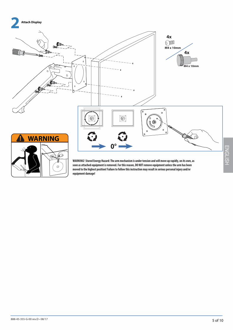
888-45-355-G-00 rev.D • 08/17 5 of 10
2
M4 x 10mm
M4 x 10mm
4x
4x
WARNING 0°
ENGLISH
Attach Display
WARNING! Stored Energy Hazard: The arm mechanism is under tension and will move up rapidly, on its own, as
soon as attached equipment is removed. For this reason, DO NOT remove equipment unless the arm has been
moved to the highest position! Failure to follow this instruction may result in serious personal injury and/or
equipment damage!
888-45-355-G-00 rev.D • 08/17 6 of 10
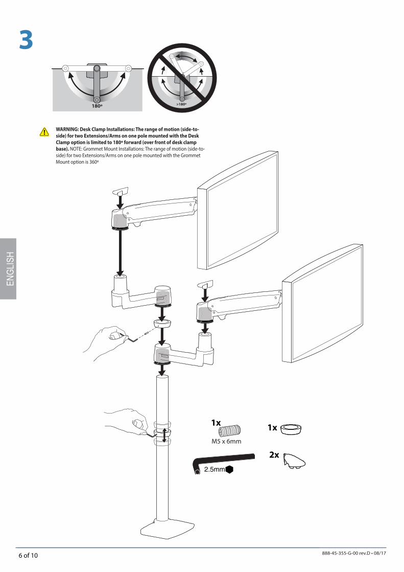
3
180º >180º
2.5mm
M5 x 6mm
1x1x
2x
ENGL
ISH
WARNING: Desk Clamp Installations: The range of motion (side-to-
side) for two Extensions/Arms on one pole mounted with the Desk
Clamp option is limited to 180º forward (over front of desk clamp
base). NOTE: Grommet Mount Installations: The range of motion (side-to-side) for two Extensions/Arms on one pole mounted with the Grommet Mount option is 360º
888-45-355-G-00 rev.D • 08/17 7 of 10
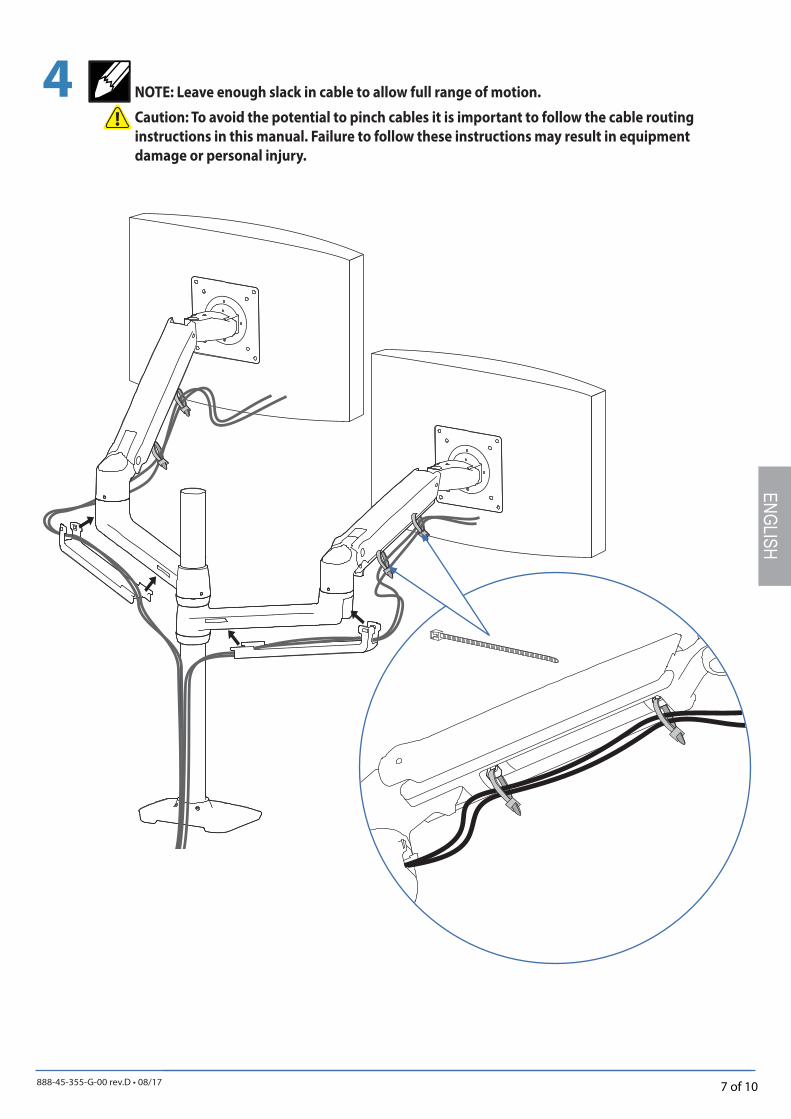
4
ENGLISH
NOTE: Leave enough slack in cable to allow full range of motion.
Caution: To avoid the potential to pinch cables it is important to follow the cable routing
instructions in this manual. Failure to follow these instructions may result in equipment
damage or personal injury.
888-45-355-G-00 rev.D • 08/17 8 of 10
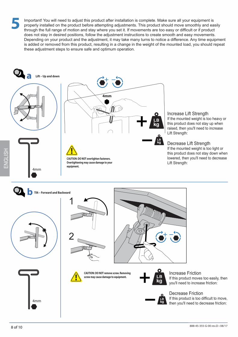
5
4mm
4mm
a
b
4mm
1
2
ENGL
ISH
CAUTION: DO NOT overtighten fasteners.
Overtightening may cause damage to your
equipment.
Lift – Up and down
Tilt – Forward and Backward
CAUTION: DO NOT remove screw. Removing
screw may cause damage to equipment.Increase FrictionIf this product moves too easily, then you'll need to increase friction:
Decrease FrictionIf this product is too diffi cult to move, then you'll need to decrease friction:
Important! You will need to adjust this product after installation is complete. Make sure all your equipment is properly installed on the product before attempting adjustments. This product should move smoothly and easily through the full range of motion and stay where you set it. If movements are too easy or diffi cult or if product does not stay in desired positions, follow the adjustment instructions to create smooth and easy movements. Depending on your product and the adjustment, it may take many turns to notice a difference. Any time equipment is added or removed from this product, resulting in a change in the weight of the mounted load, you should repeat these adjustment steps to ensure safe and optimum operation.
Increase Lift StrengthIf the mounted weight is too heavy or this product does not stay up when raised, then you'll need to increase Lift Strength:
Decrease Lift StrengthIf the mounted weight is too light or this product does not stay down when lowered, then you'll need to decrease Lift Strength:
888-45-355-G-00 rev.D • 08/17 9 of 10
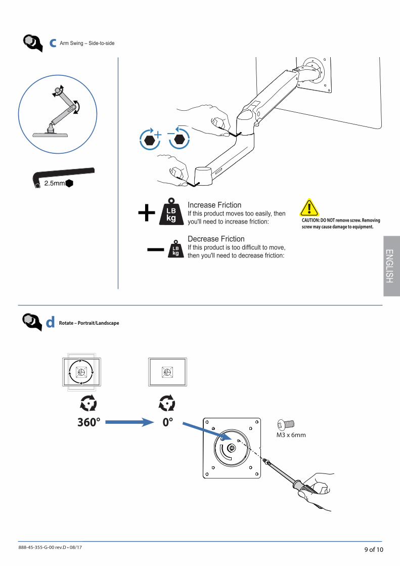
360° 0°M3 x 6mm
c
d
2.5mm
ENGLISH
Rotate – Portrait/Landscape
Increase FrictionIf this product moves too easily, then you'll need to increase friction:
Decrease FrictionIf this product is too diffi cult to move, then you'll need to decrease friction:
CAUTION: DO NOT remove screw. Removing
screw may cause damage to equipment.
Arm Swing – Side-to-side

888-45-355-G-00 rev.D • 08/17 10 of 10
© 2016 Ergotron, Inc. All rights reserved.
ENGL
ISH
Learn more about ergonomic computer use at:www.computingcomfort.org
Set Your Workstation to Work For YOU!
Height Position top of screen slightly below eye level. Position keyboard at about elbow height with wrists fl at. Distance Position screen an arm's length from face—at least 20” (508mm). Position keyboard close enough to create a 90˚ angle in elbow. Angle Tilt screen to eliminate glare. Tilt the keyboard back 10° so that your wrists remain fl at.
To Reduce FatigueBreathe - Breathe deeply through your nose.Blink - Blink often to avoid dry eyes.Break • 2 to 3 minutes every 20 minutes• 15 to 20 minutes every 2 hours.
For local customer care phone numbers visit: http://contact.ergotron.comFor Service visit: www.ergotron.comFor Warranty visit: www.ergotron.com/warranty