
Users Guide and Operation Manual for K3 - DTG...
90
Users Guide and Operation Manual for K3 Version 2.0
Transcript of Users Guide and Operation Manual for K3 - DTG...

Users Guide and Operation Manual for K3
Version 2.0
DTG K3TM User Guide V2.0
i
Contents Important Safety Instructions ............................................................................ 4
1 Introducing high quality DTG Digital Printers ........................................................... 6
1.1 The DTG K3™ .......................................................................................... 6
1.2 DTG TEX Textile Inks ................................................................................ 7
White Ink Properties and Maintenance ................................................................. 7
Using Other Ink Brands .................................................................................... 7
Using Other Ink Types ..................................................................................... 8
2 Before you Get Started ...................................................................................... 9
2.1 Commit to Maintenance ............................................................................. 9
2.2 Get to Know your K3 ................................................................................. 9
3 Getting Started .............................................................................................. 10
3.1 Unpacking and Positioning the DTG K3™ ....................................................... 11
4 Printer Components ........................................................................................ 13
4.1 Front ................................................................................................. 13
4.2 Rear .................................................................................................. 14
4.3 Left Side ............................................................................................. 15
4.4 Right Side ............................................................................................ 16
4.5 Power & Communication Ports ................................................................... 16
4.6 Emergency Stop Switch ........................................................................... 17
4.7 WIMS (White Ink Management System) ......................................................... 18
4.8 WIMS Control Panel ................................................................................ 19
REST Dial .................................................................................................. 19
STIR Dial ................................................................................................... 19
Mode Indicator LED ...................................................................................... 19
Mode Button .............................................................................................. 19
AOD system. .............................................................................................. 20
4.9 Colour Inks Tray .................................................................................... 21
4.10 Printer Head & Carriage ........................................................................ 22
4.11 Control Panel ..................................................................................... 23
5 Prepare the DTG K3TM for Printing ...................................................................... 24
5.1 Filling Ink Bottles ................................................................................... 24
Pour Inks into the Ink Bottles: ......................................................................... 24
5.2 Drawing Ink from the Ink Bottles to the Print Head .......................................... 25
5.3 Monitor and Empty the Waste Ink Container as Needed ..................................... 28
5.4 Installing and Using Printer Drivers ............................................................. 29
To Install Printer Driver: ............................................................................... 29
DTG K3TM User Guide V2.0
ii
6 Basic Printer Operations .................................................................................. 31
6.1 Control Panel LCD display, Buttons and Lights ................................................ 31
Control Panel Buttons ................................................................................... 31
Control Panel Button Summary ........................................................................ 33
Button ..................................................................................................... 33
Control Panel Lights ..................................................................................... 34
Bed Up / Down Buttons ................................................................................. 35
LCD Display Indicators .................................................................................. 36
Ink Lights (1-8) ........................................................................................... 37
6.2 Loading Media ...................................................................................... 38
6.3 Printing a Nozzle Check Pattern ................................................................. 39
6.4 Print Head Cleaning ................................................................................ 42
6.5 Clean using Cleaning Pump Assembly ........................................................... 42
7 Printing on Textiles with the DTG K3™ ................................................................ 43
Printable Area of the DTG K3 .......................................................................... 43
7.1 Prepare Your Image ................................................................................ 44
Vectors .................................................................................................... 44
Bitmaps .................................................................................................... 45
Resolution ................................................................................................. 45
Empty Space in the Image .............................................................................. 46
Image Sharpness & Saturation ......................................................................... 46
Transparent Backgrounds............................................................................... 46
7.2 Garment Preparation .............................................................................. 48
7.3 Load Garment to Platen / Platen to Printer ................................................... 51
Put the Garment on to the Platen .................................................................... 51
Adjust Printing Bed Height / Move Platen to the Top of Page position ......................... 52
Print Your Image. ........................................................................................ 53
After Printing Has Finished. ............................................................................ 53
Removing INK SPOTS .................................................................................... 53
HEAT CURE Your Finished Print ....................................................................... 53
WASHING Garments ..................................................................................... 54
7.4 Cancelling a Print Job ............................................................................. 54
8 General Care and Maintenance of your DTG K3 ...................................................... 55
8.1 Execute a Print Head Clean at the end of production ....................................... 55
8.2 Turn the DTG K3 off each night via the keypad ............................................... 55
8.3 Moisten the print head when not in use ........................................................ 55
DTG K3TM User Guide V2.0
iii
8.4 Run the Epson Head Cleaning and Nozzle Check utilities each day before starting production ................................................................................................... 56
8.5 Manually wipe the Print Head Face ............................................................. 57
8.6 Clean the Wiper Blade ............................................................................ 58
8.7 Clean the Capping Station ........................................................................ 60
8.8 Empty the sneezing station ....................................................................... 62
8.9 Empty the capping station drip tray ............................................................ 63
8.10 Empty the waste ink bottle .................................................................... 64
8.11 Clean the CR Encoder Strip .................................................................... 65
8.12 Clean and Lubricate the Print Head Guide Rails ........................................... 66
8.13 Clean the Drive Roller and Belt ............................................................... 66
8.14 Environmental Conditions ...................................................................... 67
8.15 Clean your DTG K3™ ............................................................................. 67
8.16 Cover your DTG K3™ ............................................................................ 67
8.17 Avoid White Ink Separation .................................................................... 67
8.18 Ink Levels ......................................................................................... 67
8.19 Pre-Treat garments away from the printer ................................................. 68
8.20 Flush the White Ink Manifold & Dampers every 7 – 10 days .............................. 68
8.21 Decline in Print Quality ......................................................................... 70
8.22 Aligning the Print Head ......................................................................... 71
8.23 Waste Ink Bottle Maintenance ................................................................. 74
8.24 Removing and Replacing Dampers ............................................................ 75
8.25 If Printer is Not Used for Some Time ......................................................... 76
8.26 Print Head Replacement ....................................................................... 76
9 Trouble-shooting ............................................................................................ 77
9.1 Control Panel Light Indicators ................................................................... 77
9.2 Problems during Printing .......................................................................... 78
9.3 Problems with Curing / Washing ................................................................. 83
10 Transporting or Storing Your Printer ................................................................ 85
10.1 Preparing the printer for transportation / storage ........................................ 85
11 Product Support .......................................................................................... 86
12 Requirements for PC .................................................................................... 87
13 Printer Specifications ................................................................................... 88
Limited Warranty Registration Card .......................................................................... 89
DTG K3TM User Guide V2.0
4
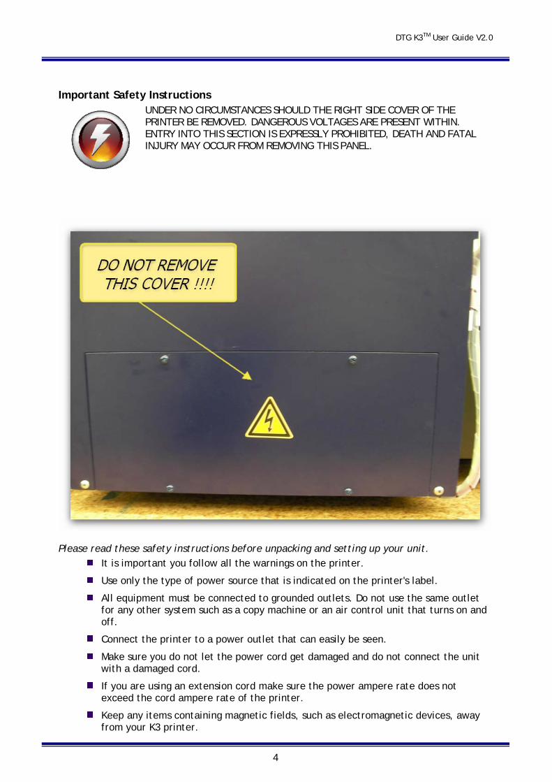
Important Safety Instructions
UNDER NO CIRCUMSTANCES SHOULD THE RIGHT SIDE COVER OF THE PRINTER BE REMOVED. DANGEROUS VOLTAGES ARE PRESENT WITHIN. ENTRY INTO THIS SECTION IS EXPRESSLY PROHIBITED, DEATH AND FATAL INJURY MAY OCCUR FROM REMOVING THIS PANEL.
Please read these safety instructions before unpacking and setting up your unit. It is important you follow all the warnings on the printer.
Use only the type of power source that is indicated on the printer's label.
All equipment must be connected to grounded outlets. Do not use the same outlet for any other system such as a copy machine or an air control unit that turns on and off.
Connect the printer to a power outlet that can easily be seen.
Make sure you do not let the power cord get damaged and do not connect the unit with a damaged cord.
If you are using an extension cord make sure the power ampere rate does not exceed the cord ampere rate of the printer.
Keep any items containing magnetic fields, such as electromagnetic devices, away from your K3 printer.
DTG K3TM User Guide V2.0
5
Keep the printer away from locations with high humidity, vibrations, debris or dust.
Leave enough space around the printer for proper ventilation.
Prevent any sudden shocks to your printer, such as dropping the unit.
Do not leave the printer near heat sources such as radiators, heat vents, or direct sunlight.
Place the printer on a flat table or on a stable surface that extends around the printer. The printer will not work properly if it is on an uneven surface or tilted or leaning in any way.
Be careful when transporting the printer – keep it upright (not on its side or upside down) so you do not spill the ink.
Always turn the printer off before cleaning and clean with a damp cloth only. Do not spill any liquid on the printer.
Caution: Do not unplug the printer to shut it off. Use the power button instead. Do not unplug the printer until the green power light is off.
Do not block any of the printer's vents or insert anything foreign in its slots.
Do not try to service the printer yourself, except where described in this manual. If you need service, turn the printer off, unplug it and take it to your DTG Dealer or authorized Distributor
Safety Instructions for Using the Printer and Handling Ink
Always keep ink and other consumables out of the reach of children.
Be careful not to spill ink on your skin or in your eyes. If any ink does get on your skin wash it thoroughly with soap and water. If ink gets in your eyes flush them out immediately with water.
Do not put your hand in the printer or touch the dampers once printing.
Do not move the printer head by hand; doing so may damage the printer.
Store the ink in a cool dark place.
If you store the inks in a cold environment and are ready to use them, bring them to room temperature before you use them.
DTG K3TM User Guide V2.0
6
1 Introducing high quality DTG Digital Printers DTG Digital printers are one of the most distinct ranges of inkjet flat bed printers available today. These direct inkjet printers are capable of printing on many different materials, even materials with light and / or uneven surfaces.
Using our specialised textile pigment inks, you can print directly to cotton or cotton blend fabrics, such as those used in T-Shirts. There is a short pre-treatment process required for printing with white ink (such as to dark fabrics), and the only post-treatment is that of heat drying to cure the inks.
Most other print materials will need to be pretreated with a special ink-receptive pre-coatings (Undercoats), and placed on the printer flat tray to be printed with the high- quality piezo drop-on-demand print head. The printed media is dried sufficiently and over coated with top-coats which protect the printed images from water and UV rays. Please check with your DTG Distributor for availability.
1.1 The DTG K3™
The DTG K3™ is a textile printing unit based on an Epson 1900 inkjet printer. In other words, it is basically an inkjet printer head technology. It uses standard inkjet technology with DTG TEX Textile Ink to print on any type of cotton / cotton blend garment or fabric material.
Prior to the development of DTG Tex textile inks for inkjet printers, printing on fabric with an inkjet printer used to be quite difficult – standard inkjet inks that are used to print on paper do not stand up to regular washing when printed onto most fabrics. DTG TEX Textile inks have been specifically designed to print on fabrics and garments with only a post treatment of heat needed to set the ink. DTG Tex White Ink has been specifically designed for printing to dark fabrics and garments, and additionally requires a pre-treatment to be sprayed to the fabric / garments. There are now numerous water based pigment inks from a number of ink manufacturers that work well.
By using DTG TEX Inks, the DTG K3™ will successfully print on light coloured 100% cotton, 50% cotton/50% polyester blends, 100% polyester (light colored only) and many other natural and synthetic materials. Depending on the image you are printing, 100% cotton will produce the brightest prints, as the colours on 100% polyester and polyester and cotton blends may appear slightly dull.
For darker coloured garments requiring a white ink underbase, your DTG K3™ will produce excellent results on 100% and low polyester (<30%) content cotton blends. We do however recommend test printing ALL fabrics prior to production.
There are many applications for DTG K3™ printing. Besides T-Shirts, it can print on ladies tops, men’s polo shirts, tote bags, aprons, towels, caps, mouse pads and bibs. Some products will require pre-treatment with either DTG Poly pre treatment or White ink Pre treatment when printing with white ink.
DTG K3TM User Guide V2.0
7
The DTG K3™ with White Ink will require not only the standard Windows printer driver for you computer, but also our specially developed RIP program which “interprets” the image data and converts it to instructions relating to the printing of white ink for the printer. Printer Drivers for Windows and the RIP software have been included in your DTG K3™ package. You can create your artwork from many graphic applications such as Adobe Photoshop, Adobe Illustrator, Adobe InDesign, CorelDRAW, QuarkXPress, Macromedia Freehand, convert it (where necessary) to a format which can be read by our RIP, and then open that image from within the RIP for printing to your garment or fabric.
1.2 DTG TEX Textile Inks The Epson 1900 printer, and therefore the DTG K3™, has eight channels of colour in it’s print head. Each channel passes ink through the print head by way of 180 very fine (< 0.075 mm diameter) nozzles .
In the DTG K3™ with White Ink, 4 colours are replaced with White Ink. White Ink is a water based titanium dioxide / binder / carrier mix. The titanium dioxide is ground into a fine powder and mixed with other binders to allow it to dry and adhere to the pre-treated fabric. Titanium dioxide is what gives the ink its bright white properties, and this brightness gives the coloured ink layer a vibrant and rich colour.
White Ink Properties and Maintenance Because of the chemical properties of white ink it requires much more maintenance than the colour inks. Titanium dioxide is a mineral and does not dissolve in liquids. This means that the titanium dioxide will, over a period of time, settle to the bottom of the container (being the ink bottles, ink tubes and / or dampers). Once complete, separation of the titanium dioxide from the binders and other components in the ink cannot be reversed! Your K3 has a ground breaking WIMS system that keeps the ink “moving” in the ink tubes and dampers, however it is recommended that at minimum you perform a head clean on the printer every day when you are not printing with white ink, and preferably that you also print a small image with white ink daily.
If the DTG K3™ has not printed white ink for a few days, you may need to execute 1-3 head cleans in a row to move sufficient ink to overcome the separation in the dampers and print head.
Using Other Ink Brands Your DTG K3™ package included bottles of DTG TEX Textile Inks. This is a specially formulated, water based pigment ink. DO NOT mix other ink brands with your DTG TEX Textile inks. This can create major problems. While we strongly recommend you use only DTG TEX Textile inks, if you do decide to try another brand of textile ink you must flush out the complete ink system using a specially formulated flushing solution available from your DTG Dealer before putting another brand of ink into your system. Mixing inks, even a very small amount, may cause severe and permanent clogging of the printing head.

DTG K3TM User Guide V2.0
8
Using Other Ink Types Similarly, if you wish to change your ink type from DTG TEX for printing on non-textile materials (or vice-versa), you will need to thoroughly flush the DTG K3™ ink system of the old ink before charging with the new ink. Whilst this process is relatively straight-forward, it will take approximately ½ - 1 hour of your time, and does “waste” a fair amount of ink.
Never attempt to use a non-water based ink in your DTG K3™ – even mild solvent based inks may cause irreparable damage to the ink tubes, dampers or even the print head.
Your DTG Dealer or Agent cannot guarantee the performance of inks used in the DTG printer models. There are numerous brands available from third party suppliers, and as all inks are made by third parties DTG DOES NOT warrant any inks used in our printing system.

DTG K3TM User Guide V2.0
9
2 Before you Get Started 2.1 Commit to Maintenance Your DTG K3 represents a significant investment, not only of your money but also of your commitment to your new business opportunity with the DTG K3.
Whilst the mechanics of the K3 are essentially the same as that of a normal inkjet printer, printing on fabric is not the same as printing on paper. Fabric generates much more dust, printing on fabrics requires a much greater volume of ink, and the white ink pre-treatment can become airborne during spraying and can ingress into the K3. Each of these factors individually can cause problems with your DTG K3, and in combination can be critical to the ongoing operation of the K3. All is not lost, however! A few minutes of your time each day spent undertaking some basic maintenance tasks on the K3 will ensure it’s continued optimal performance. Please refer to the sections within this User’s Guide on Preventative Maintenance for further information.
2.2 Get to Know your K3
Starting a new business or adding to your existing product line with the DTG K3 is a very exciting, and potentially very profitable time. Don’t get too carried away though and start accepting orders before you even have your printer. Allow plenty of time to become familiar with your K3 and to learn not only the basics, but also the variables that can impact on your finished product. These variables include image types, fabric types, your operating environment, garment preparation, and curing of the garment. Thoroughly read this manual, ask questions of your DTG Technician or Distributor, talk to other users (see various internet forums). Be prepared to ruin a few shirts. Be realistic about deadlines when accepting orders and allow yourself sufficient time (and perhaps a couple of extra garments) to complete the order.
DTG K3TM User Guide V2.0
10
3 Getting Started
Read all instructions through thoroughly (including the safety instructions) before unpacking your DTG K3TM unit, and then follow the relevant directions as you prepare your unit for printing.
Prepare an area to set up your DTG K3TM unit (refer Section 3.1 below).
Unpack and set up the unit as per the instructions in Section 3.1 of this manual.
Familiarise yourself with the various parts of your DTG K3TM (Section 4)
Fill the ink bottles CAREFULLY (Section5.1 ).
Install the Printer Drivers and the RIP software. Go to www.Epson.com for more information on the Epson 1900, and to download complete printer manuals, the latest drivers and driver fixes for use with your DTG K3™.
Perform the bi-directional head alignment operation as explained in the relevant section. It is likely you will have to enter all nine in all fields three or four times in succession if this is the first time your printer has been used.
Read Section 6.3 on printing t-shirts. This section explains what the control panel buttons and lights are for, the basic steps to printing on a t-shirt and how to cancel a print job.
Section 8 covers general maintenance and problems you may encounter with the printing process.
Section 9 is a troubleshooting guide
DTG K3TM User Guide V2.0
11
3.1 Unpacking and Positioning the DTG K3™
Keep all packaging, holding fixtures and instructions for the DTG K3™ as you will need them if you have to transport your system anywhere or to return it for repair. There is a section in the back of this manual on transporting your printer. Please ensure you read and follow these instructions.
Please read the following directions through before unpacking your DTG K3™:
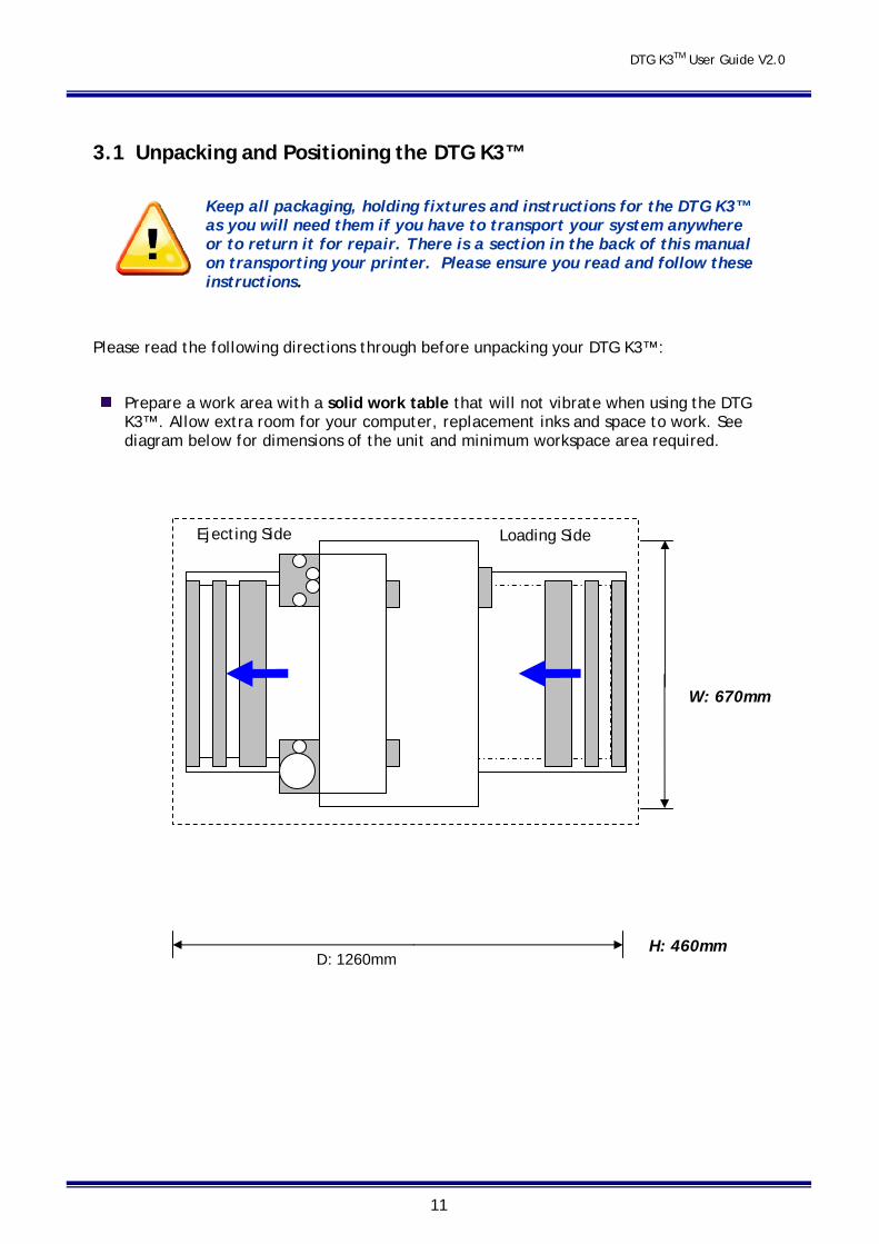
Prepare a work area with a solid work table that will not vibrate when using the DTG K3™. Allow extra room for your computer, replacement inks and space to work. See diagram below for dimensions of the unit and minimum workspace area required.
Ejecting Side
W: 670mm
D: 1260mm H: 460mm
Loading Side

DTG K3TM User Guide V2.0
12
Carefully remove the printer from the box, taking hold of it by the front and rear roller side covers.
Place the printer on the work table which should be levelled first. The unit must be kept away from direct sunlight, dusty areas, excessively high humidity, strong magnetic forces and direct airflow which can dry out and clog the printing heads. It is recommended that the unit be kept in an air-conditioned environment, with temperatures no less than 5° Celsius (41°F) and no more than 30° Celsius (86°F) with humidity levels between 40 and 70%.
Provide a separate room for the spraying of pre-treatment to the garments prior to printing. If a separate room is not possible, you must allow a minimum of 5m between the spray station and the DTG K3, and ensure that forced extraction of the pre-treat vapour is carried out. Failure to adhere to these recommendations will result in erratic print quality and the need for numerous head cleans both before and during printing. This erratic behaviour is likely to worsen until the print head fails and has to be replaced.
Protect any carpet or floor covering with mats or old carpet as there is a risk of spilling wet ink when you refill the bulk ink bottles.
Place the DTG K3™ close to the heat source that you are using to cure the ink so that you have a smooth workflow, but ensure that heat does not radiate directly on to the DTG K3™. If you have more than one DTG K3™, place them around the heat source or close to it.
When you have placed the DTG K3™ unit on the floor, remove the any packaging covering the unit. Check the unit carefully for shipping damage. If you find any obvious damage please contact the freight carrier immediately to arrange a freight inspection.
Remove any tape holding the waste ink and waste bottles in place.
Connect the power supply cable and the printer interface (USB or parallel) cable with your PC. Do not use an interface cable that is longer than 1.8 meters. If you must use a USB Hub, please ensure that the hub has it’s own power supply, otherwise erratic prints may result.
DTG K3TM User Guide V2.0
13
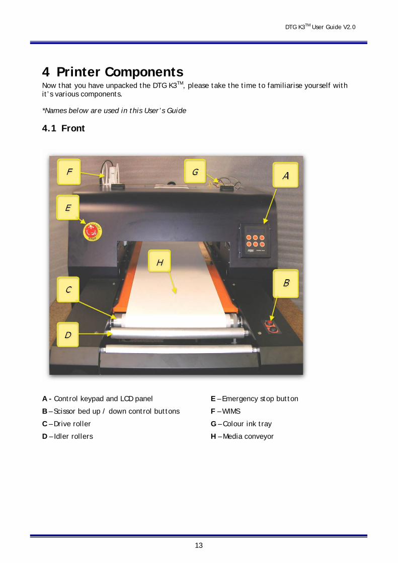
4 Printer Components Now that you have unpacked the DTG K3TM, please take the time to familiarise yourself with it’s various components.
*Names below are used in this User’s Guide
4.1 Front
A - Control keypad and LCD panel
B – Scissor bed up / down control buttons
C – Drive roller
D – Idler rollers
E – Emergency stop button
F – WIMS
G – Colour ink tray
H – Media conveyor
DTG K3TM User Guide V2.0
14
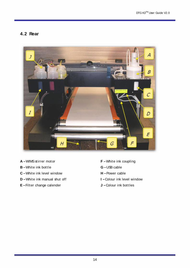
4.2 Rear
A – WIMS stirrer motor
B – White ink bottle
C – White ink level window
D – White ink manual shut off
E – Filter change calender
F – White ink coupling
G – USB cable
H – Power cable
I – Colour ink level window
J – Colour ink bottles
DTG K3TM User Guide V2.0
15
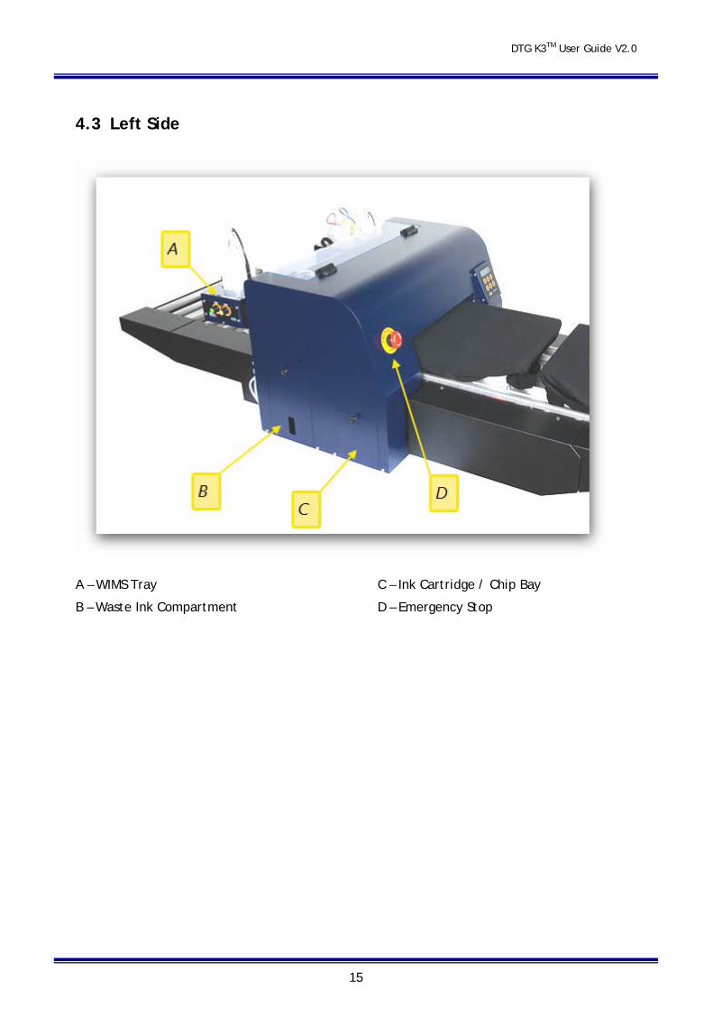
4.3 Left Side
A – WIMS Tray
B – Waste Ink Compartment
C – Ink Cartridge / Chip Bay
D – Emergency Stop
DTG K3TM User Guide V2.0
16
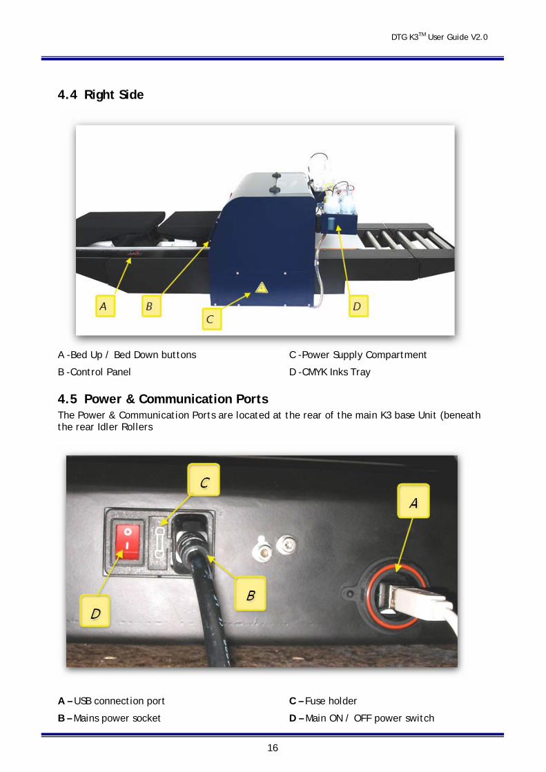
4.4 Right Side
A -Bed Up / Bed Down buttons
B -Control Panel
C -Power Supply Compartment
D -CMYK Inks Tray
4.5 Power & Communication Ports The Power & Communication Ports are located at the rear of the main K3 base Unit (beneath the rear Idler Rollers
A – USB connection port
B – Mains power socket
C – Fuse holder
D – Main ON / OFF power switch
DTG K3TM User Guide V2.0
17
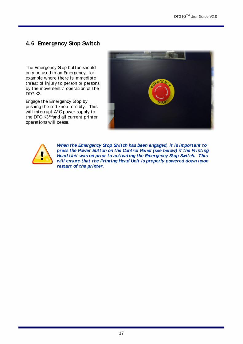
4.6 Emergency Stop Switch
The Emergency Stop button should only be used in an Emergency, for example where there is immediate threat of injury to person or persons by the movement / operation of the DTG K3.
Engage the Emergency Stop by pushing the red knob forcibly. This will interrupt A/C power supply to the DTG K3™ and all current printer operations will cease.
When the Emergency Stop Switch has been engaged, it is important to press the Power Button on the Control Panel (see below) if the Printing Head Unit was on prior to activating the Emergency Stop Switch. This will ensure that the Printing Head Unit is properly powered down upon restart of the printer.
DTG K3TM User Guide V2.0
18
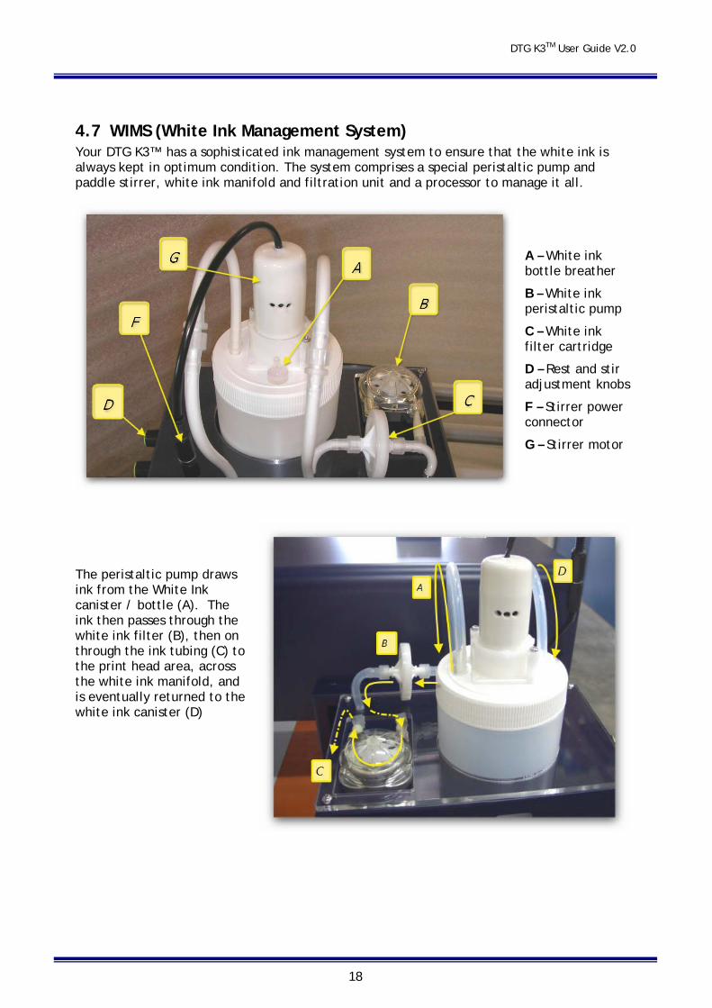
4.7 WIMS (White Ink Management System) Your DTG K3™ has a sophisticated ink management system to ensure that the white ink is always kept in optimum condition. The system comprises a special peristaltic pump and paddle stirrer, white ink manifold and filtration unit and a processor to manage it all.
A – White ink bottle breather
B – White ink peristaltic pump
C – White ink filter cartridge
D – Rest and stir adjustment knobs
F – Stirrer power connector
G – Stirrer motor
The peristaltic pump draws ink from the White Ink canister / bottle (A). The ink then passes through the white ink filter (B), then on through the ink tubing (C) to the print head area, across the white ink manifold, and is eventually returned to the white ink canister (D)
DTG K3TM User Guide V2.0
19
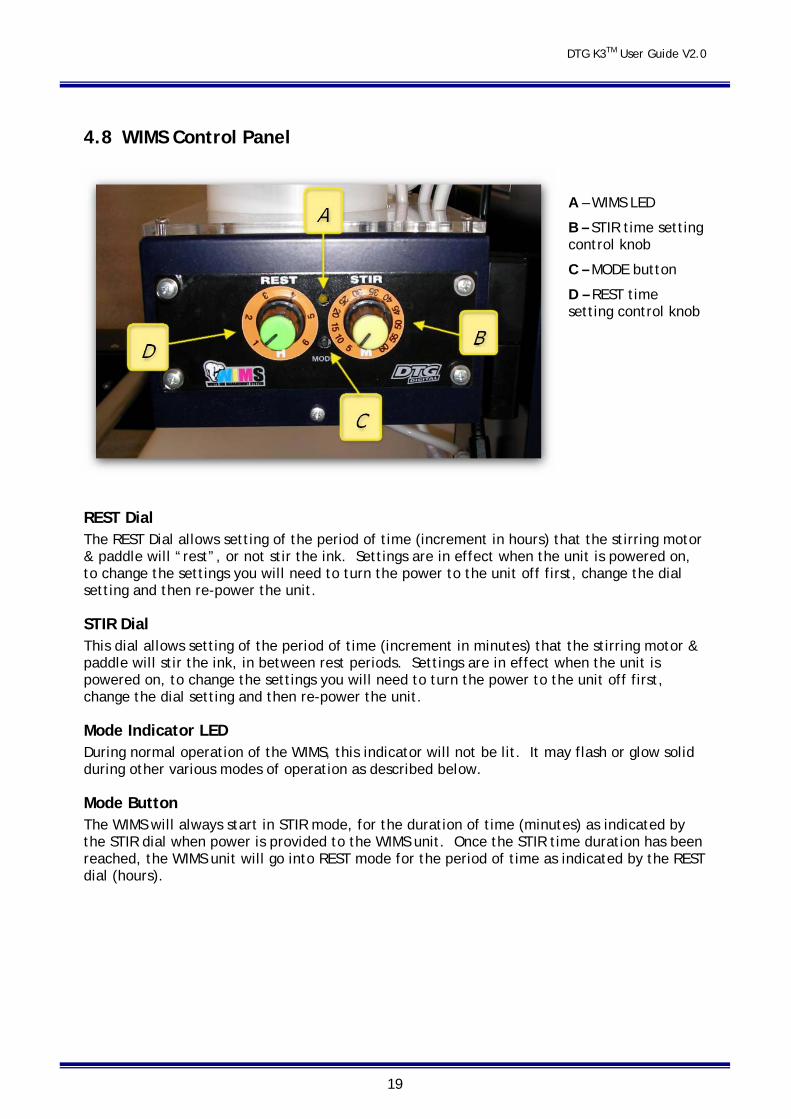
4.8 WIMS Control Panel
A – WIMS LED
B – STIR time setting control knob
C – MODE button
D – REST time setting control knob
REST Dial The REST Dial allows setting of the period of time (increment in hours) that the stirring motor & paddle will “rest”, or not stir the ink. Settings are in effect when the unit is powered on, to change the settings you will need to turn the power to the unit off first, change the dial setting and then re-power the unit.
STIR Dial This dial allows setting of the period of time (increment in minutes) that the stirring motor & paddle will stir the ink, in between rest periods. Settings are in effect when the unit is powered on, to change the settings you will need to turn the power to the unit off first, change the dial setting and then re-power the unit.
Mode Indicator LED During normal operation of the WIMS, this indicator will not be lit. It may flash or glow solid during other various modes of operation as described below.
Mode Button The WIMS will always start in STIR mode, for the duration of time (minutes) as indicated by the STIR dial when power is provided to the WIMS unit. Once the STIR time duration has been reached, the WIMS unit will go into REST mode for the period of time as indicated by the REST dial (hours).

DTG K3TM User Guide V2.0
20
Diagnostic Mode: By pressing & holding the Mode button as the WIMS unit is powered up, the WIMS unit is set to diagnostic mode. As the motor / paddle stirs, the Mode indicator LED will flash for the number of minute increments as shown on the STIR dial indicator. When the motor / paddle rests, the Mode Indicator LED will flash for the number of hour increments as shown on the REST dial indicator. This mode is useful to confirm the calibration of the dial indicators. For example – referring to the photograph above of the control panel, the REST dial is set between 2-3 hours (2 time increments), and the STIR dial is set to approximately 15 minutes (3 time increments). In Diagnostic Mode, the motor will stir for approximately 3 seconds, and the Mode Indicator LED will flash 3 times (representing the 3 time increments for stirring) . The motor will then stop stirring for approximately 2 seconds, and the Mode Indicator LED will flash 2 times (representing 2 full rest time increments).
Manual Override: Whilst the WIMS unit is in normal operating mode, if you press & hold the Mode Button for 2-3 seconds, it will go into manual override – ON mode, and the motor will continuously stir. Whilst in this mode, if the mode button is pressed & held for 2-3 seconds, the unit will go into manual override – OFF mode, and the unit will stop stirring and reset to normal operating mode.
The basic setup and test for the WIMS system is as follows:
Set the stir period in five minute graduations
Set the rest period in one hour graduations
Hold the mode button and apply power
Count the flashes and monitor the WIMS activity
AOD system. The AOD (Agitation On Demand) system is designed to maximize pump and stirrer life whilst ensuring that the ink delivery is in optimum condition at all times. The AOD sender board monitors the active state of the printer. When the printer has been inactive for approximately 7 minutes it enters a stand-by mode and the AOD allows the timer setting in the WIMS to manage not only the ink stirring, but also the ink circulation. If a print job or any other action requiring the printer engine to function is started the AOD will sense this and over-ride the WIMS timer causing the WIMS circulation to activate.
DTG K3TM User Guide V2.0
21
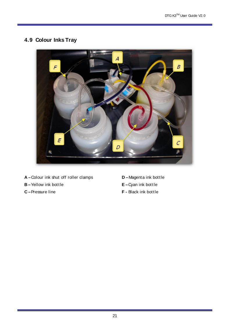
4.9 Colour Inks Tray
A – Colour ink shut off roller clamps
B – Yellow ink bottle
C – Pressure line
D – Magenta ink bottle
E – Cyan ink bottle
F - Black ink bottle
DTG K3TM User Guide V2.0
22
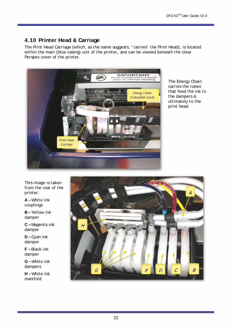
4.10 Printer Head & Carriage The Print Head Carriage (which, as the name suggests, “carries” the Print Head), is located within the main (blue casing) unit of the printer, and can be viewed beneath the clear Perspex cover of the printer.
The Energy Chain carries the tubes that feed the ink to the dampers & ultimately to the print head.
This image is taken from the rear of the printer:
A – White ink couplings
B – Yellow ink damper
C – Magenta ink damper
D – Cyan ink damper
F – Black ink damper
G – White ink dampers
H – White ink manifold
DTG K3TM User Guide V2.0
23
The Print Head itself is seated beneath the dampers and within the Print Head Carriage, and the printing face of the Print Head protrudes from beneath the Print Head Carriage.
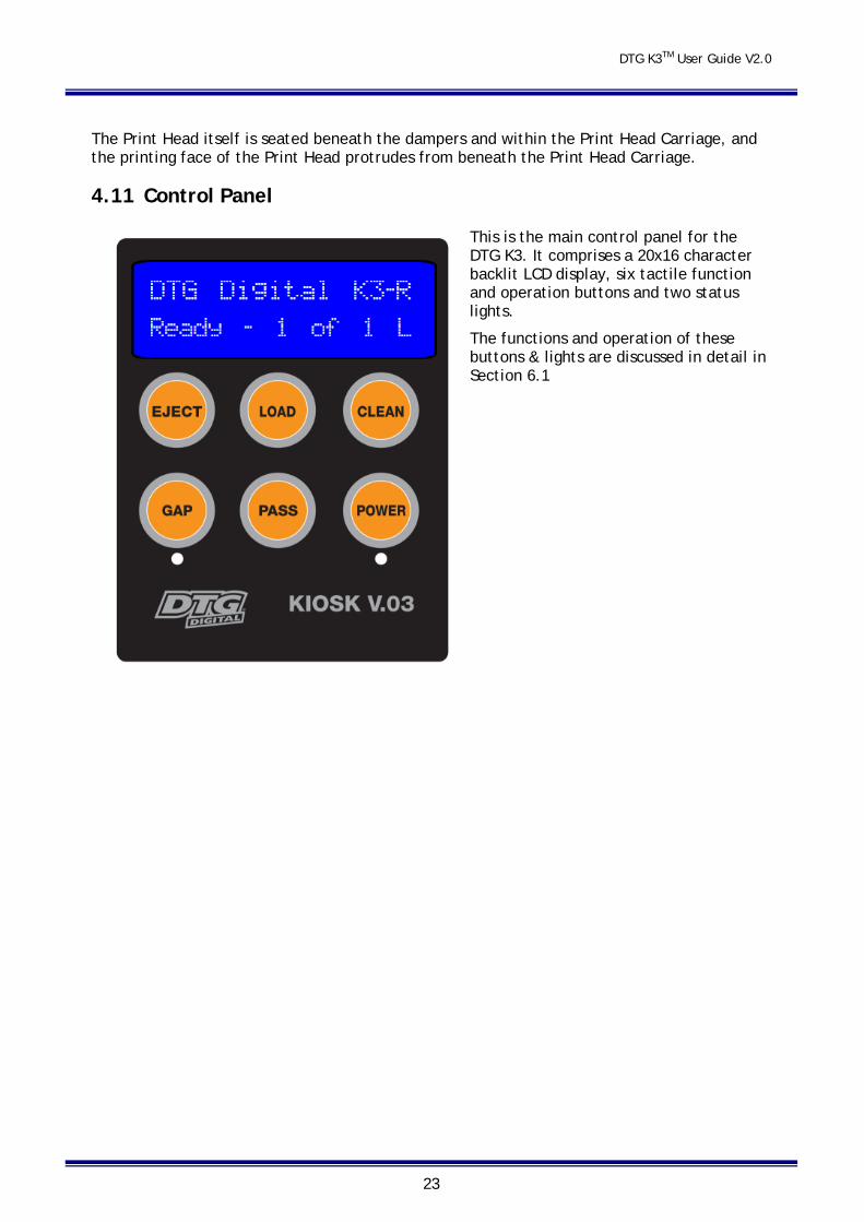
4.11 Control Panel
This is the main control panel for the DTG K3. It comprises a 20x16 character backlit LCD display, six tactile function and operation buttons and two status lights.
The functions and operation of these buttons & lights are discussed in detail in Section 6.1
DTG K3TM User Guide V2.0
24
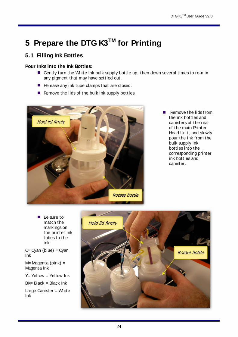
5 Prepare the DTG K3TM for Printing 5.1 Filling Ink Bottles
Pour Inks into the Ink Bottles: Gently turn the White Ink bulk supply bottle up, then down several times to re-mix
any pigment that may have settled out.
Release any ink tube clamps that are closed.
Remove the lids of the bulk ink supply bottles.
Remove the lids from the ink bottles and canisters at the rear of the main Printer Head Unit, and slowly pour the ink from the bulk supply ink bottles into the corresponding printer ink bottles and canister.
Be sure to match the markings on the printer ink tubes to the ink:
C= Cyan (blue) = Cyan Ink
M= Magenta (pink) = Magenta Ink
Y= Yellow = Yellow Ink
BK= Black = Black Ink
Large Canister = White Ink
DTG K3TM User Guide V2.0
25
Pour the ink gently so as to avoid creating air bubbles when pouring the ink. If bubbles are formed then do not run the printer until the majority of bubbles have settled (leave to settle for an hour or so).
Ink levels in the printer ink bottles should be maintained at ½ to ¾ full at all times. In particular, the White Ink level must never be let go below 40%, doing so could cause the ink tubes to draw air into the system, requiring a re-charge of inks to re-fill the ink tubes. It is recommended that the inks be topped up each night as part of the shut down maintenance routine, however levels should also be monitored & corrected during periods of high productivity on the printer.
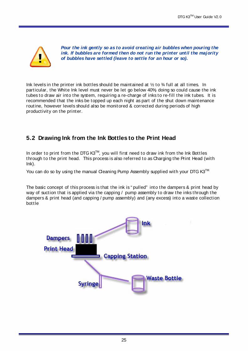
5.2 Drawing Ink from the Ink Bottles to the Print Head
In order to print from the DTG K3TM, you will first need to draw ink from the Ink Bottles through to the print head. This process is also referred to as Charging the Print Head (with Ink).
You can do so by using the manual Cleaning Pump Assembly supplied with your DTG K3TM.
The basic concept of this process is that the ink is “pulled” into the dampers & print head by way of suction that is applied via the capping / pump assembly to draw the inks through the dampers & print head (and capping /pump assembly) and (any excess) into a waste collection bottle
DTG K3TM User Guide V2.0
26
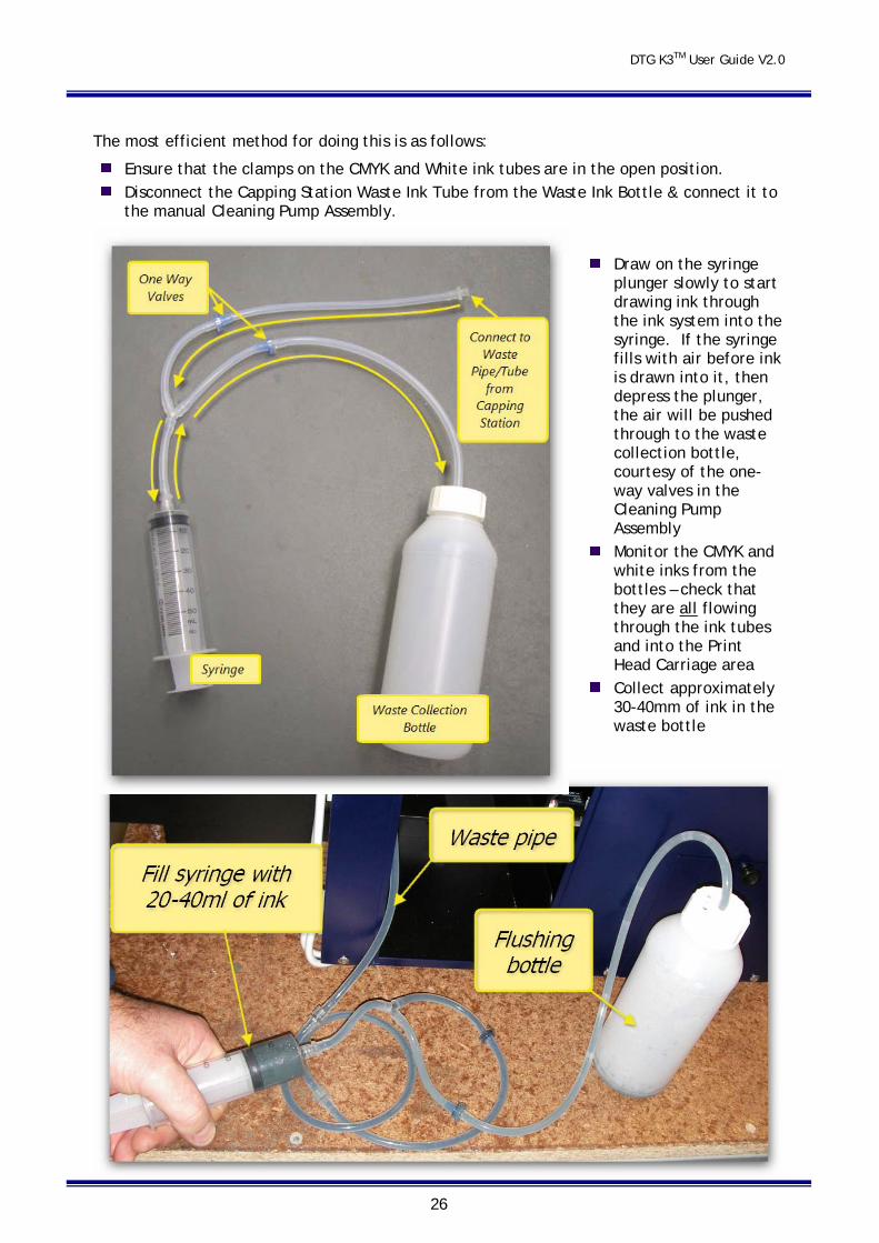
The most efficient method for doing this is as follows:
Ensure that the clamps on the CMYK and White ink tubes are in the open position. Disconnect the Capping Station Waste Ink Tube from the Waste Ink Bottle & connect it to
the manual Cleaning Pump Assembly.
Draw on the syringe plunger slowly to start drawing ink through the ink system into the syringe. If the syringe fills with air before ink is drawn into it, then depress the plunger, the air will be pushed through to the waste collection bottle, courtesy of the one-way valves in the Cleaning Pump Assembly
Monitor the CMYK and white inks from the bottles – check that they are all flowing through the ink tubes and into the Print Head Carriage area
Collect approximately 30-40mm of ink in the waste bottle

DTG K3TM User Guide V2.0
27
Disconnect the Waste Ink Tube from the Cleaning Pump Assembly and re-connect it to the Waste Ink Bottle.
Clean the Print Head:
Power the DTG K3TM on.
Once the LCD Display reads READY, place a platen on the Media Conveyor belt and press the load button, after the platen loads then press clean button briefly to clean the head. This will normalize the head nozzles.
It is recommended that you allow the printer to “rest” now for 15 minutes or so prior to
running test prints - this will allow any air bubbles in the inks to settle somewhat prior to printing.
From this point on, you will simply need to add ink to the bulk ink bottles as you use the system. Take care to avoid creating bubbles when doing so. Or alternatively, add ink after production has finished for the day, allowing bubbles to settle overnight before again using the printer. Remember to keep ink bottles between 50% and 75% full at all times.
Always wash and clean your Cleaning Pump Assembly after every use!
DTG K3TM User Guide V2.0
28
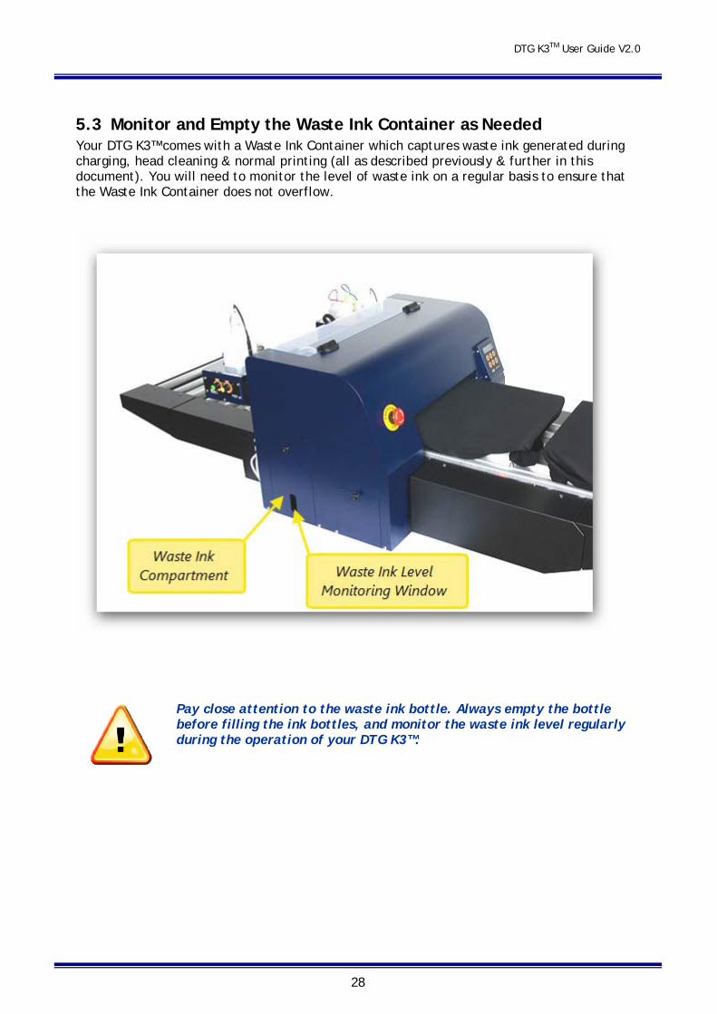
5.3 Monitor and Empty the Waste Ink Container as Needed Your DTG K3™ comes with a Waste Ink Container which captures waste ink generated during charging, head cleaning & normal printing (all as described previously & further in this document). You will need to monitor the level of waste ink on a regular basis to ensure that the Waste Ink Container does not overflow.
Pay close attention to the waste ink bottle. Always empty the bottle before filling the ink bottles, and monitor the waste ink level regularly during the operation of your DTG K3™.
DTG K3TM User Guide V2.0
29
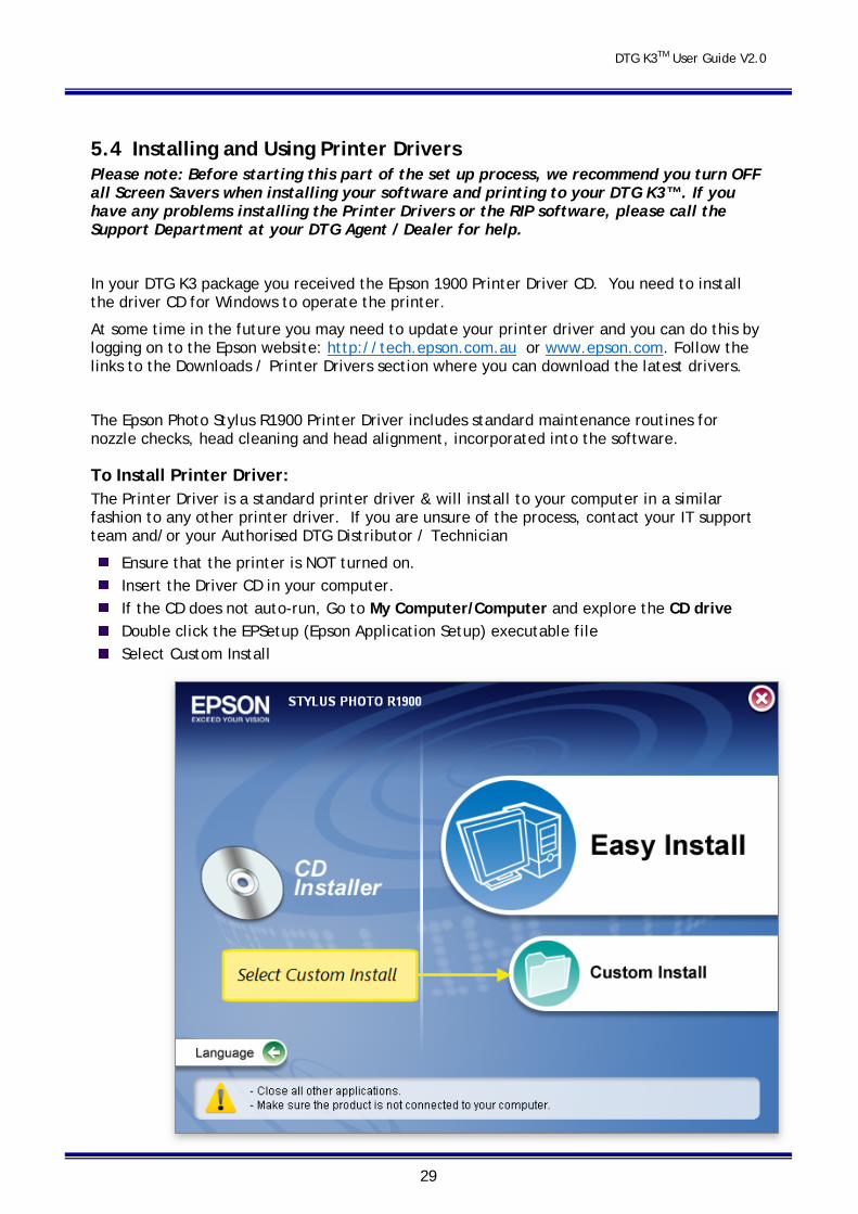
5.4 Installing and Using Printer Drivers Please note: Before starting this part of the set up process, we recommend you turn OFF all Screen Savers when installing your software and printing to your DTG K3™. If you have any problems installing the Printer Drivers or the RIP software, please call the Support Department at your DTG Agent / Dealer for help.
In your DTG K3 package you received the Epson 1900 Printer Driver CD. You need to install the driver CD for Windows to operate the printer.
At some time in the future you may need to update your printer driver and you can do this by logging on to the Epson website: http://tech.epson.com.au or www.epson.com. Follow the links to the Downloads / Printer Drivers section where you can download the latest drivers.
The Epson Photo Stylus R1900 Printer Driver includes standard maintenance routines for nozzle checks, head cleaning and head alignment, incorporated into the software.
To Install Printer Driver: The Printer Driver is a standard printer driver & will install to your computer in a similar fashion to any other printer driver. If you are unsure of the process, contact your IT support team and/or your Authorised DTG Distributor / Technician
Ensure that the printer is NOT turned on. Insert the Driver CD in your computer. If the CD does not auto-run, Go to My Computer/Computer and explore the CD drive Double click the EPSetup (Epson Application Setup) executable file Select Custom Install
DTG K3TM User Guide V2.0
30
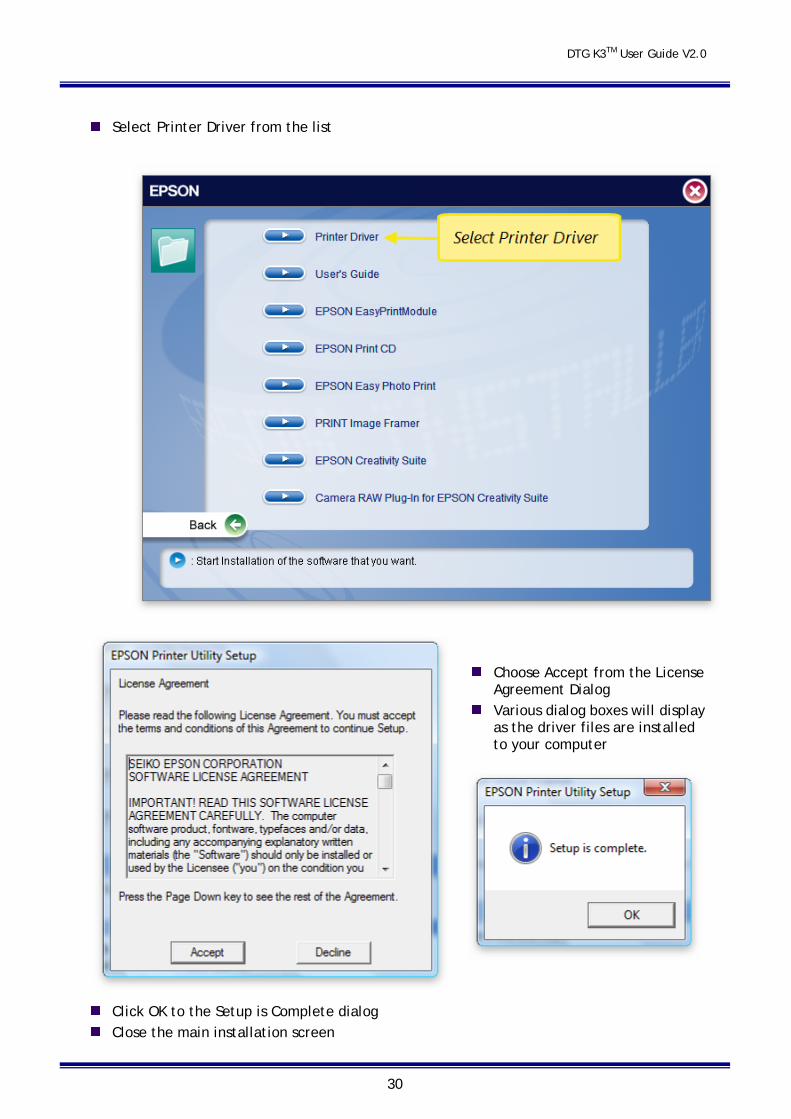
Select Printer Driver from the list
Choose Accept from the License Agreement Dialog
Various dialog boxes will display as the driver files are installed to your computer
Click OK to the Setup is Complete dialog Close the main installation screen

DTG K3TM User Guide V2.0
31
6 Basic Printer Operations 6.1 Control Panel LCD display, Buttons and Lights
Before you start to work with your printer, you need to understand the Control Panel and what its buttons and lights mean. Read this section again before you attempt to print with your printer.
Control Panel Buttons
The Power button turns the Printing Head Unit on or off. Note that the main A/c power to the base unit must be connected to the A/C Power Port and switched on at the A/C Power Switch in order for this button, and in fact most functions of the Control Panel to be operable.
The CLEAN button on the DTG K3™ is used as a HEAD CLEANING button. Press this button for 4 seconds to clean the printer head When the printer is in a loaded status. To move the head out from the capping station press this button when the printer is in a Not loaded status. There is a built in safety timer which will return the head to the capping station after 4 minutes.
DTG K3TM User Guide V2.0
32
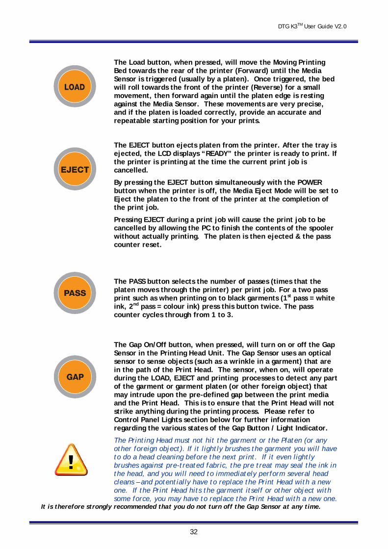
The Load button, when pressed, will move the Moving Printing Bed towards the rear of the printer (Forward) until the Media Sensor is triggered (usually by a platen). Once triggered, the bed will roll towards the front of the printer (Reverse) for a small movement, then forward again until the platen edge is resting against the Media Sensor. These movements are very precise, and if the platen is loaded correctly, provide an accurate and repeatable starting position for your prints.
The EJECT button ejects platen from the printer. After the tray is ejected, the LCD displays “READY” the printer is ready to print. If the printer is printing at the time the current print job is cancelled.
By pressing the EJECT button simultaneously with the POWER button when the printer is off, the Media Eject Mode will be set to Eject the platen to the front of the printer at the completion of the print job.
Pressing EJECT during a print job will cause the print job to be cancelled by allowing the PC to finish the contents of the spooler without actually printing. The platen is then ejected & the pass counter reset.
The PASS button selects the number of passes (times that the platen moves through the printer) per print job. For a two pass print such as when printing on to black garments (1st pass = white ink, 2nd pass = colour ink) press this button twice. The pass counter cycles through from 1 to 3.
The Gap On/Off button, when pressed, will turn on or off the Gap Sensor in the Printing Head Unit. The Gap Sensor uses an optical sensor to sense objects (such as a wrinkle in a garment) that are in the path of the Print Head. The sensor, when on, will operate during the LOAD, EJECT and printing processes to detect any part of the garment or garment platen (or other foreign object) that may intrude upon the pre-defined gap between the print media and the Print Head. This is to ensure that the Print Head will not strike anything during the printing process. Please refer to Control Panel Lights section below for further information regarding the various states of the Gap Button / Light Indicator.
The Printing Head must not hit the garment or the Platen (or any other foreign object). If it lightly brushes the garment you will have to do a head cleaning before the next print. If it even lightly brushes against pre-treated fabric, the pre treat may seal the ink in the head, and you will need to immediately perform several head cleans – and potentially have to replace the Print Head with a new one. If the Print Head hits the garment itself or other object with some force, you may have to replace the Print Head with a new one.
It is therefore strongly recommended that you do not turn off the Gap Sensor at any time.
DTG K3TM User Guide V2.0
33
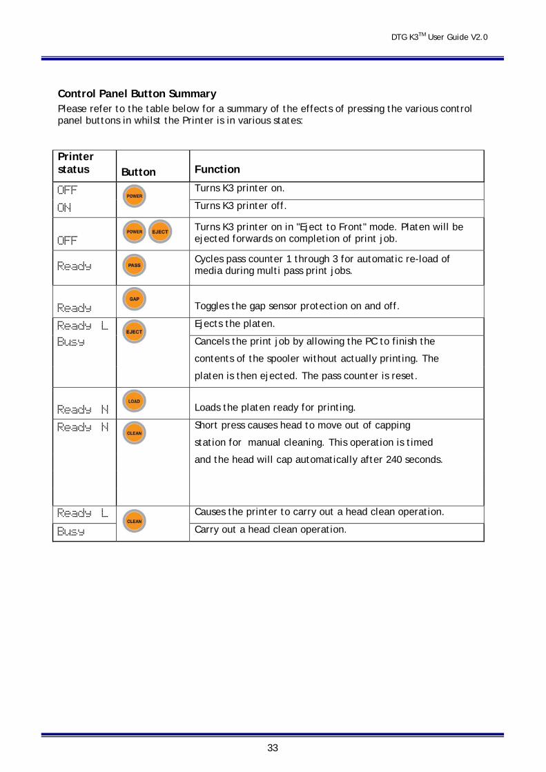
Control Panel Button Summary Please refer to the table below for a summary of the effects of pressing the various control panel buttons in whilst the Printer is in various states:
Printer status Button Function
OFF
Turns K3 printer on.
ON Turns K3 printer off.
OFF Turns K3 printer on in "Eject to Front" mode. Platen will be ejected forwards on completion of print job.
Ready
Cycles pass counter 1 through 3 for automatic re-load of media during multi pass print jobs.
Ready Toggles the gap sensor protection on and off.
Ready L
Ejects the platen.
Busy Cancels the print job by allowing the PC to finish the
contents of the spooler without actually printing. The
platen is then ejected. The pass counter is reset.
Ready N Loads the platen ready for printing.
Ready N
Short press causes head to move out of capping
station for manual cleaning. This operation is timed
and the head will cap automatically after 240 seconds.
Ready L
Causes the printer to carry out a head clean operation.
Busy Carry out a head clean operation.
DTG K3TM User Guide V2.0
34
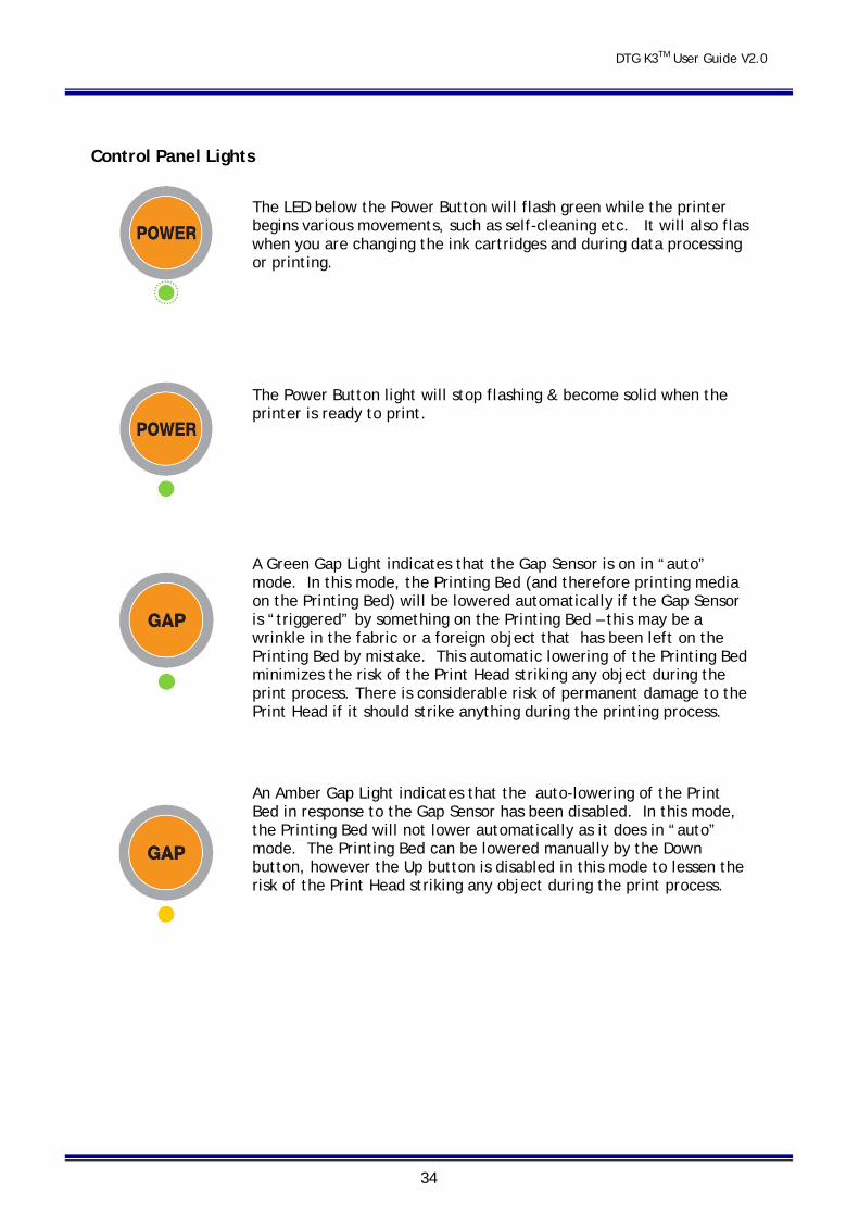
Control Panel Lights
The LED below the Power Button will flash green while the printer begins various movements, such as self-cleaning etc. It will also flas when you are changing the ink cartridges and during data processing or printing.
The Power Button light will stop flashing & become solid when the printer is ready to print.
A Green Gap Light indicates that the Gap Sensor is on in “auto” mode. In this mode, the Printing Bed (and therefore printing media on the Printing Bed) will be lowered automatically if the Gap Sensor is “triggered” by something on the Printing Bed – this may be a wrinkle in the fabric or a foreign object that has been left on the Printing Bed by mistake. This automatic lowering of the Printing Bed minimizes the risk of the Print Head striking any object during the print process. There is considerable risk of permanent damage to the Print Head if it should strike anything during the printing process.
An Amber Gap Light indicates that the auto-lowering of the Print Bed in response to the Gap Sensor has been disabled. In this mode, the Printing Bed will not lower automatically as it does in “auto” mode. The Printing Bed can be lowered manually by the Down button, however the Up button is disabled in this mode to lessen the risk of the Print Head striking any object during the print process.
DTG K3TM User Guide V2.0
35
A Red Gap Light indicates that the Gap Sensor is “triggered”
Bed Up / Down Buttons
The raising and lowering of the scissor bed is controlled via the BED up and down buttons located on the top side of the left front cover.
The UP button, when pressed, will raise the Moving Printing Bed (and therefore any media that is positioned on it) until the button is released, the upper limit is reached OR until the Gap Sensor Beam is triggered (which will automatically stop the upward movement of the Moving Printing Bed.
The DOWN button, when pressed, will lower the Moving Printing Bed (and therefore any media that is positioned on it), until the button is released or the lower limit is reached.
When the GAP light is green, both the up and down buttons will operate.
When the GAP light is orange, the automatic raising and lowering is disabled and only a manual DOWN function can be carried out.
When the GAP light is red, the GAP system has detected that the beam is interrupted and there is a possible head strike danger.
The bed will actively move down until either the obstacle is removed or the bed reaches is maximum lower limit.
DTG K3TM User Guide V2.0
36
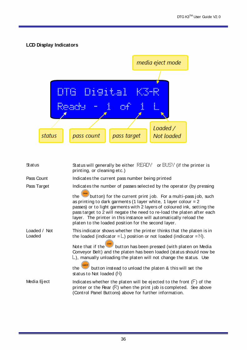
LCD Display Indicators
Status Status will generally be either READY or BUSY (if the printer is printing, or cleaning etc.)
Pass Count Indicates the current pass number being printed
Pass Target Indicates the number of passes selected by the operator (by pressing
the button) for the current print job. For a multi-pass job, such as printing to dark garments (1 layer white, 1 layer colour = 2 passes) or to light garments with 2 layers of coloured ink, setting the pass target to 2 will negate the need to re-load the platen after each layer. The printer in this instance will automatically reload the platen to the loaded position for the second layer.
Loaded / Not Loaded
This indicator shows whether the printer thinks that the platen is in the loaded (indicator = L) position or not loaded (indicator = N).
Note that if the button has been pressed (with platen on Media Conveyor Belt) and the platen has been loaded (status should now be L), manually unloading the platen will not change the status. Use
the button instead to unload the platen & this will set the status to Not loaded (N)
Media Eject Indicates whether the platen will be ejected to the front (F) of the printer or the Rear (R) when the print job is completed. See above (Control Panel Buttons) above for further information.
DTG K3TM User Guide V2.0
37
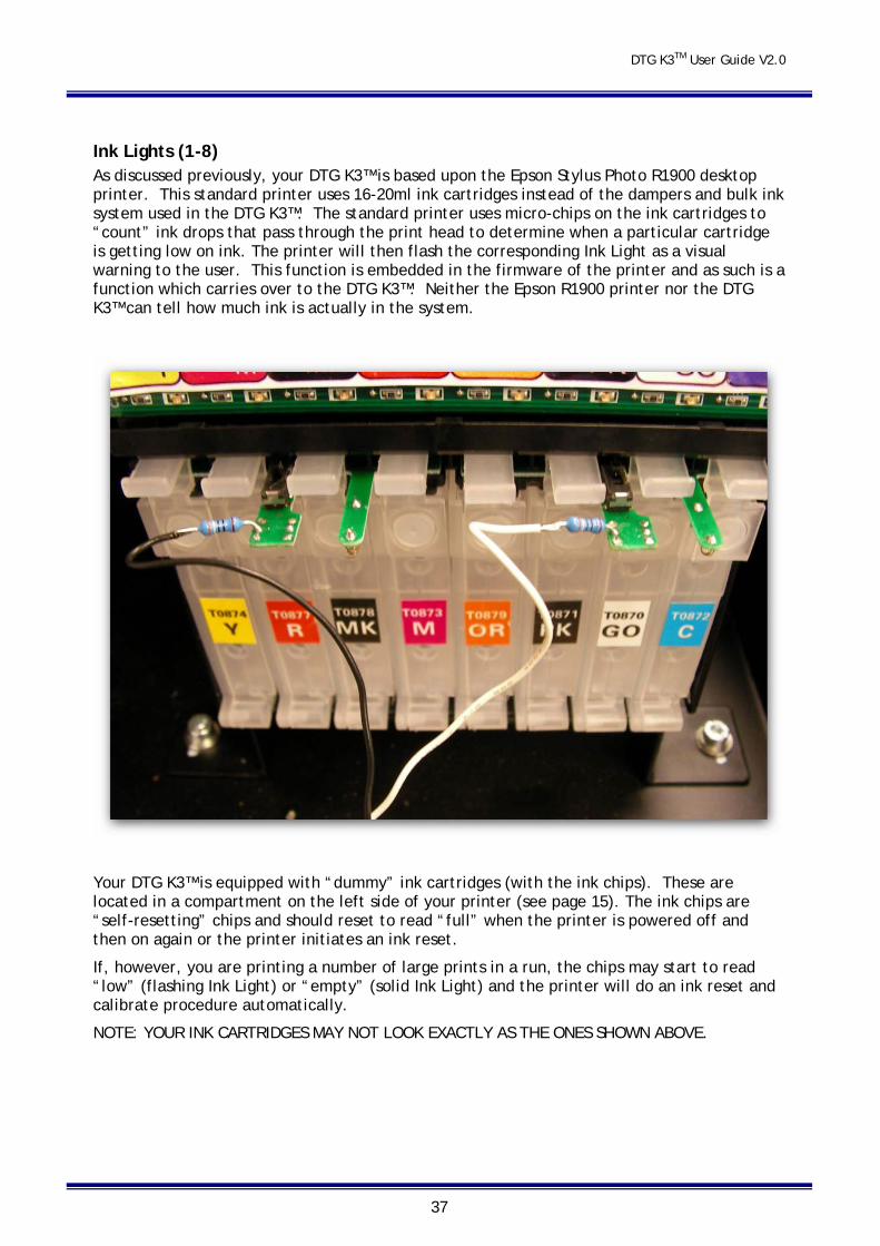
Ink Lights (1-8) As discussed previously, your DTG K3™ is based upon the Epson Stylus Photo R1900 desktop printer. This standard printer uses 16-20ml ink cartridges instead of the dampers and bulk ink system used in the DTG K3™. The standard printer uses micro-chips on the ink cartridges to “count” ink drops that pass through the print head to determine when a particular cartridge is getting low on ink. The printer will then flash the corresponding Ink Light as a visual warning to the user. This function is embedded in the firmware of the printer and as such is a function which carries over to the DTG K3™. Neither the Epson R1900 printer nor the DTG K3™ can tell how much ink is actually in the system.
Your DTG K3™ is equipped with “dummy” ink cartridges (with the ink chips). These are located in a compartment on the left side of your printer (see page 15). The ink chips are “self-resetting” chips and should reset to read “full” when the printer is powered off and then on again or the printer initiates an ink reset.
If, however, you are printing a number of large prints in a run, the chips may start to read “low” (flashing Ink Light) or “empty” (solid Ink Light) and the printer will do an ink reset and calibrate procedure automatically.
NOTE: YOUR INK CARTRIDGES MAY NOT LOOK EXACTLY AS THE ONES SHOWN ABOVE.
DTG K3TM User Guide V2.0
38
6.2 Loading Media In order to start printing, you will first have to ensure that the media to which you wish to print is properly loaded to the “top of page” or “origin” position in the printer.
In addition, you need to ensure that your media is close enough to the print head during printing that you achieve good quality prints. If the media is set too low, the spray of ink from the print head can be diffused and create an unclear print. At the same time, it is important to not set the media too high so that it may cause the Print Head to brush or even strike it during printing. The Gap Sensor should be utilized to set the optimum media height:
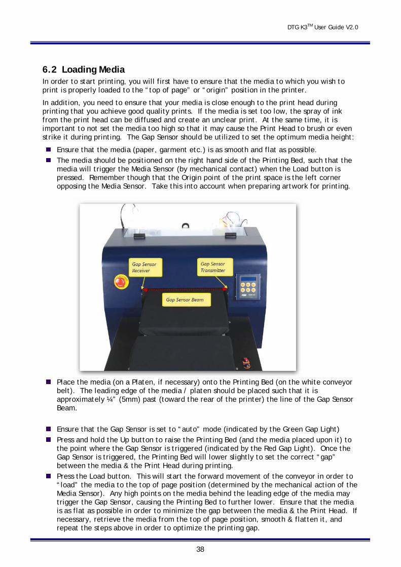
Ensure that the media (paper, garment etc.) is as smooth and flat as possible. The media should be positioned on the right hand side of the Printing Bed, such that the
media will trigger the Media Sensor (by mechanical contact) when the Load button is pressed. Remember though that the Origin point of the print space is the left corner opposing the Media Sensor. Take this into account when preparing artwork for printing.
Place the media (on a Platen, if necessary) onto the Printing Bed (on the white conveyor belt). The leading edge of the media / platen should be placed such that it is approximately ¼” (5mm) past (toward the rear of the printer) the line of the Gap Sensor Beam.
Ensure that the Gap Sensor is set to “auto” mode (indicated by the Green Gap Light) Press and hold the Up button to raise the Printing Bed (and the media placed upon it) to
the point where the Gap Sensor is triggered (indicated by the Red Gap Light). Once the Gap Sensor is triggered, the Printing Bed will lower slightly to set the correct “gap” between the media & the Print Head during printing.
Press the Load button. This will start the forward movement of the conveyor in order to “load” the media to the top of page position (determined by the mechanical action of the Media Sensor). Any high points on the media behind the leading edge of the media may trigger the Gap Sensor, causing the Printing Bed to further lower. Ensure that the media is as flat as possible in order to minimize the gap between the media & the Print Head. If necessary, retrieve the media from the top of page position, smooth & flatten it, and repeat the steps above in order to optimize the printing gap.
DTG K3TM User Guide V2.0
39
6.3 Printing a Nozzle Check Pattern To check that the Print head is fully charged with Ink and ready to print, you will need to print a Nozzle Check Pattern.
You should also print these Nozzle Check Patterns each day before production and often during production if lines or gaps start to appear in your printed output. This will identify very quickly whether there are blocked nozzles in your Print head or the Print head is not fully charged with ink – which in most cases will be cleared very quickly by following through with the Head Clean / Nozzle Check cycle as described below.
Perform a Nozzle Check when the printer is in a Ready state (the Control Panel LCD Display should show READY). Use a clear thin sheet of transparent plastic or a thin sheet of stainless steel to print the nozzle check on – place it on top of and to the front and left edges of your Platen . Place the Platen so that it’s leading edge is just inside the Printing Head Unit and ensure that the gap between the top of the Platen and the Print Head is at minimum: use the Up and Down buttons to adjust the height of the Printing Bed (with printing sheet on the Platen) as described above in Section 6.2 above. Press the Load button to move the Platen to the top of page position (also described above in Section 6.2).
The Nozzle Check Pattern can be printed from the Utility tab of the Printing Preferences dialog for your Windows Epson Stylus Photo R1900 printer driver.
A printer driver is a piece of software that converts the data to be printed to the form specific to a printer. When you installed the Epson Stylus Photo R1900 driver (Section 29above), a User Interface for the driver was also installed to your computer, we also refer to this interface as the Printer Driver.
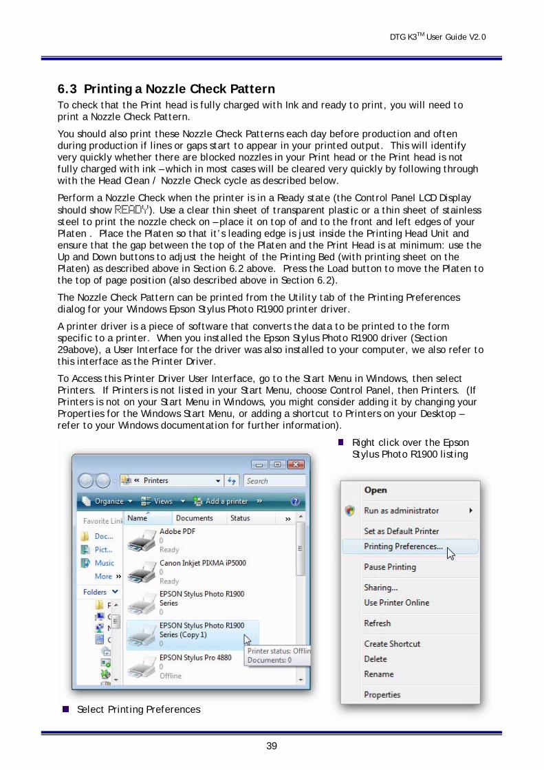
To Access this Printer Driver User Interface, go to the Start Menu in Windows, then select Printers. If Printers is not listed in your Start Menu, choose Control Panel, then Printers. (If Printers is not on your Start Menu in Windows, you might consider adding it by changing your Properties for the Windows Start Menu, or adding a shortcut to Printers on your Desktop – refer to your Windows documentation for further information).
Right click over the Epson Stylus Photo R1900 listing
Select Printing Preferences
DTG K3TM User Guide V2.0
40
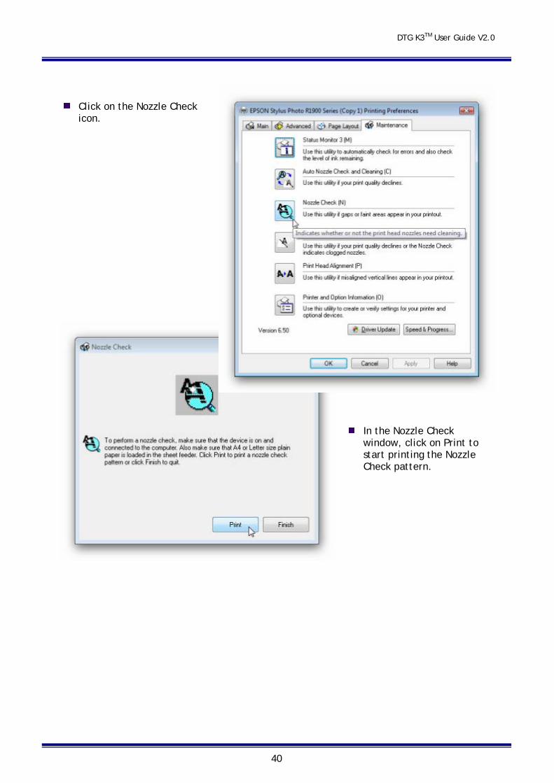
Click on the Nozzle Check icon.
In the Nozzle Check
window, click on Print to start printing the Nozzle Check pattern.
DTG K3TM User Guide V2.0
41
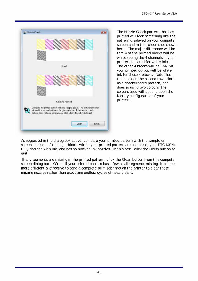
The Nozzle Check pattern that has printed will look something like the pattern displayed on your computer screen and in the screen shot shown here. The major difference will be that 4 of the printed blocks will be white (being the 4 channels in your printer allocated for white ink). The other 4 blocks will be CMY &K your printed output will be white ink for these 4 blocks. Note that the block on the second row prints as a checkerboard pattern, and does so using two colours (the colours used will depend upon the factory configuration of your printer).
As suggested in the dialog box above, compare your printed pattern with the sample on screen. If each of the eight blocks within your printed pattern are complete, your DTG K3™ is fully charged with ink, and has no blocked ink nozzles. In this case, click the Finish button to quit.
If any segments are missing in the printed pattern, click the Clean button from this computer screen dialog box. Often, if your printed pattern has a few small segments missing, it can be more efficient & effective to send a complete print job through the printer to clear these missing nozzles rather than executing endless cycles of head cleans.
DTG K3TM User Guide V2.0
42
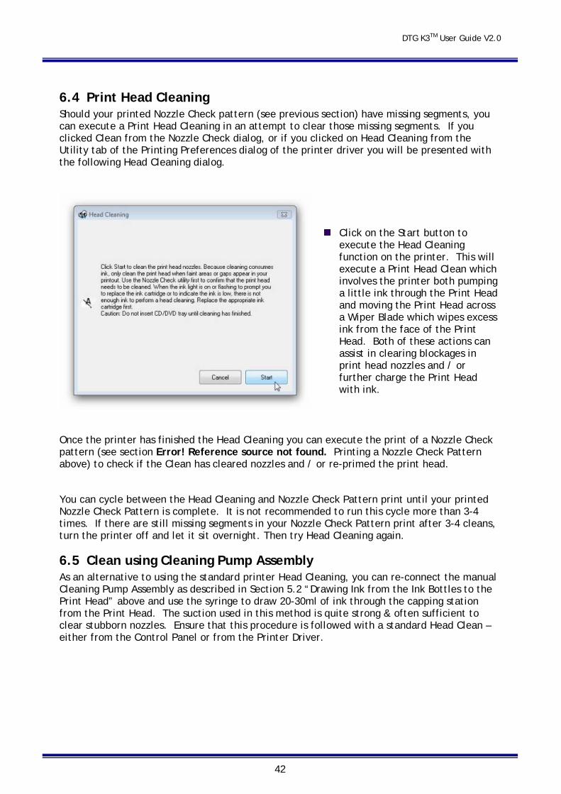
6.4 Print Head Cleaning Should your printed Nozzle Check pattern (see previous section) have missing segments, you can execute a Print Head Cleaning in an attempt to clear those missing segments. If you clicked Clean from the Nozzle Check dialog, or if you clicked on Head Cleaning from the Utility tab of the Printing Preferences dialog of the printer driver you will be presented with the following Head Cleaning dialog.
Click on the Start button to execute the Head Cleaning function on the printer. This will execute a Print Head Clean which involves the printer both pumping a little ink through the Print Head and moving the Print Head across a Wiper Blade which wipes excess ink from the face of the Print Head. Both of these actions can assist in clearing blockages in print head nozzles and / or further charge the Print Head with ink.
Once the printer has finished the Head Cleaning you can execute the print of a Nozzle Check pattern (see section Error! Reference source not found. Printing a Nozzle Check Pattern above) to check if the Clean has cleared nozzles and / or re-primed the print head.
You can cycle between the Head Cleaning and Nozzle Check Pattern print until your printed Nozzle Check Pattern is complete. It is not recommended to run this cycle more than 3-4 times. If there are still missing segments in your Nozzle Check Pattern print after 3-4 cleans, turn the printer off and let it sit overnight. Then try Head Cleaning again.
6.5 Clean using Cleaning Pump Assembly As an alternative to using the standard printer Head Cleaning, you can re-connect the manual Cleaning Pump Assembly as described in Section 5.2 “Drawing Ink from the Ink Bottles to the Print Head” above and use the syringe to draw 20-30ml of ink through the capping station from the Print Head. The suction used in this method is quite strong & often sufficient to clear stubborn nozzles. Ensure that this procedure is followed with a standard Head Clean – either from the Control Panel or from the Printer Driver.
DTG K3TM User Guide V2.0
43
7 Printing on Textiles with the DTG K3™ Printing on textile items with the DTG K3™ is a very simple process involving five easy steps:
Create an image in any of your graphics programs
Prepare a T-shirt or other textile item for printing
Load a T-shirt or other textile item onto the printer
Set-up your image for printing with the RIP program
Press the Print button.
Once you are comfortable with the basic operations of your DTG K3™, you are ready to proceed!
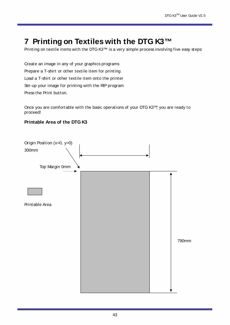
Printable Area of the DTG K3
Origin Position (x=0, y=0)
300mm
Top Margin 0mm
Printable Area
790mm
DTG K3TM User Guide V2.0
44
The diagram above refers to the entire printable area of your DTG K3™, NOT the printable area within your Shirt Platen. As the size of the Shirt Platens may vary, you will need to measure your shirt platen and set the paper size according to your measurements.
7.1 Prepare Your Image Your printed garment will only ever be as good as the artwork from which it is printed, regardless of the RIP that is used to send the printing information to the printer. It is essential that you have a basic understanding of image or graphic types in order to understand your artwork.
This User Guide is not intended to give any in depth knowledge about any particular graphics program. We offer some basic guidelines here that should be considered when preparing your artwork for printing.
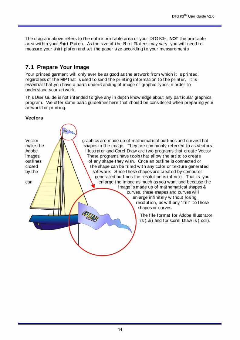
Vectors
Vector graphics are made up of mathematical outlines and curves that make the shapes in the image. They are commonly referred to as Vectors. Adobe Illustrator and Corel Draw are two programs that create Vector images. These programs have tools that allow the artist to create outlines of any shape they wish. Once an outline is connected or closed the shape can be filled with any color or texture generated by the software. Since these shapes are created by computer
generated outlines the resolution is infinite. That is, you can enlarge the image as much as you want and because the
image is made up of mathematical shapes & curves, these shapes and curves will
enlarge infinitely without losing resolution, as will any “fill” to those shapes or curves.
The file format for Adobe Illustrator is (.ai) and for Corel Draw is (.cdr).
DTG K3TM User Guide V2.0
45
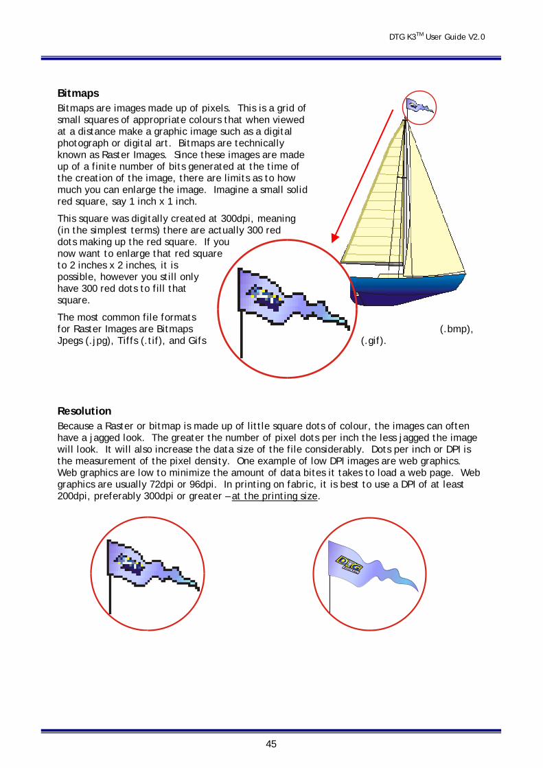
Bitmaps Bitmaps are images made up of pixels. This is a grid of small squares of appropriate colours that when viewed at a distance make a graphic image such as a digital photograph or digital art. Bitmaps are technically known as Raster Images. Since these images are made up of a finite number of bits generated at the time of the creation of the image, there are limits as to how much you can enlarge the image. Imagine a small solid red square, say 1 inch x 1 inch.
This square was digitally created at 300dpi, meaning (in the simplest terms) there are actually 300 red dots making up the red square. If you now want to enlarge that red square to 2 inches x 2 inches, it is possible, however you still only have 300 red dots to fill that square.
The most common file formats for Raster Images are Bitmaps (.bmp), Jpegs (.jpg), Tiffs (.tif), and Gifs (.gif).
Resolution Because a Raster or bitmap is made up of little square dots of colour, the images can often have a jagged look. The greater the number of pixel dots per inch the less jagged the image will look. It will also increase the data size of the file considerably. Dots per inch or DPI is the measurement of the pixel density. One example of low DPI images are web graphics. Web graphics are low to minimize the amount of data bites it takes to load a web page. Web graphics are usually 72dpi or 96dpi. In printing on fabric, it is best to use a DPI of at least 200dpi, preferably 300dpi or greater – at the printing size.
DTG K3TM User Guide V2.0
46
Programs such as Photoshop can be used to “upsample” a small, low resolution image to an image of suitable size & resolution, however you must be aware that these programs will make assumptions & calculations as to where to place the extra pixels & what colour to make them. Images that have been upsampled in this way will often have softer edges, but will be less pixilated. Unless you are proficient in graphics programs, it is always best to ask your client for a higher resolution file in the first place.
Empty Space in the Image Also ensure that there is not excessive “blank” space around the edges of the image – even blank space counts towards image size and may cause the actual image to print small in order to fit the entire image on to the platen. Trim unnecessary blank space from the top, bottom & sides of the image.
Image Sharpness & Saturation Images printed to fabric often tend to be softer & darker than what the image appears on screen. You may need to adjust images to give them a colour boost using a saturation adjustment in the graphics program, and/or sharpen the image using suitable sharpening tools within the graphics program.
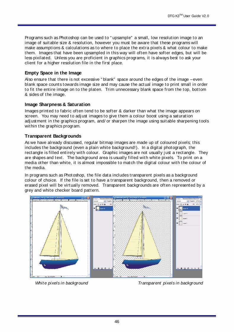
Transparent Backgrounds As we have already discussed, regular bitmap images are made up of coloured pixels; this includes the background (even a plain white background!). In a digital photograph, the rectangle is filled entirely with colour. Graphic images are not usually just a rectangle. They are shapes and text. The background area is usually filled with white pixels. To print on a media other than white, it is almost impossible to match the digital colour with the colour of the media.
In programs such as Photoshop, the file data includes transparent pixels as a background colour of choice. If the file is set to have a transparent background, then a removed or erased pixel will be virtually removed. Transparent backgrounds are often represented by a grey and white checker board pattern.
White pixels in background Transparent pixels in background
DTG K3TM User Guide V2.0
47
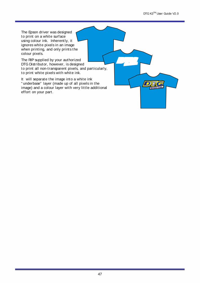
The Epson driver was designed to print on a white surface using colour ink. Inherently, it ignores white pixels in an image when printing, and only prints the colour pixels.
The RIP supplied by your authorized DTG Distributor, however, is designed to print all non-transparent pixels, and particularly, to print white pixels with white ink.
It will separate the image into a white ink “underbase” layer (made up of all pixels in the image) and a colour layer with very little additional effort on your part.
DTG K3TM User Guide V2.0
48
7.2 Garment Preparation Lint is one of the biggest enemies of the DTG K3™. By shaking your garment (away from the printer) prior to use, you can remove some of the excess lint from the garment. Pressing the garment can also help to contain excess lint. White or light coloured garments which do not need white ink require no further preparation.
Dark fabric, and some colours require a pre treatment process. The pre treat / underbase forms a special receptive surface for the white ink to adhere to. POOR PRE TREAT = POOR PRINT QUALITY. Application of the pretreatment solution is key to obtaining white opacity and ink adhesion to the fabric.
Safety
Please refer to the supplied MSDS sheet prior to use of this product. This product can be used safely when used as directed and when applicable safety
precautions are followed.
Equipment needed for proper pretreatment solution application: Respirator (disposable face mask which removes 95+% of airborne particulates (3M™ Model
# 8210 or similar) Foam Roller (the type used for painting) – optional Wide Bristle paint brush - optional Liquid Mistifier (airbrush, air pump sprayer, fine mist power sprayer, such as Wagner®
Power Sprayer Model HVLP) T-shirt Press Parchment Paper (also named Quillon paper)
Recommended procedure: The following procedure will help ensure consistent quality and performance of the White Ink:
Agitate or shake the pretreatment solution prior to filling your sprayer. Locate the sprayer area in a different room than your printer(s). Overspray can find its way into the printer and potentially damage the device.
Locate the sprayer area in a well ventilated area. Set the heat press for 170ºC (~340ºF) In humid environments, it is often beneficial to pre-press the shirt (using the parchment
paper as a barrier from the press) for 10 to 15 seconds prior to applying the pretreatment. This removes some of the water naturally trapped in the fibers. Excessively creased garments should also be pre-pressed so that the pre-treatment can be applied evenly
Using the spraying system, spray the underbase / pre-treatment evenly on the area that is to be printed. The recommended coverage is about 20g to 25g (0.7 oz to 0.9 oz) for a 14” x 17” printing area.
Set your sprayer for medium coverage. This is normally the setting between no liquid being sprayed and the maximum available.
Prime the sprayer for a few seconds by spraying into a large cup, but not on to the shirt area. This helps prevent larger drops that occur when the sprayer is starting up.
Keep the sprayer about 12 inches (0.3 meters) from the shirt and begin spraying from the top to the bottom in a left to right (and then reverse, right to left) motion without ever turning off the sprayer
DTG K3TM User Guide V2.0
49
It is good practice to allow the sprayer to go beyond the edges of the shirt before beginning or reversing direction. This prevents more pretreatment from being deposited on the shirt during the direction change.
If all settings correct, you should dispense the proper amount of pretreatment solution in about 15 seconds.
If you are printing only a small image on the garment, you can make a mask or stencil to place over the garment before spraying, so that only the required print area of the garment receives the pre-treatment. This will save on pre-treatment.
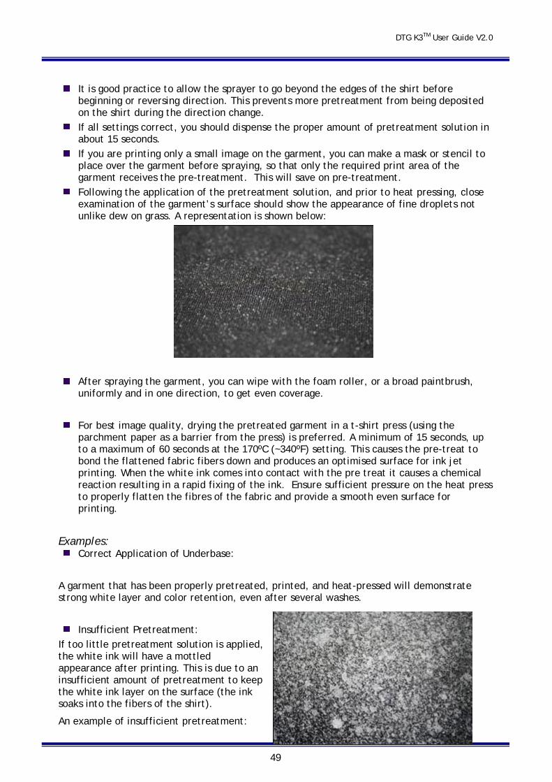
Following the application of the pretreatment solution, and prior to heat pressing, close examination of the garment’s surface should show the appearance of fine droplets not unlike dew on grass. A representation is shown below:
After spraying the garment, you can wipe with the foam roller, or a broad paintbrush, uniformly and in one direction, to get even coverage.
For best image quality, drying the pretreated garment in a t-shirt press (using the parchment paper as a barrier from the press) is preferred. A minimum of 15 seconds, up to a maximum of 60 seconds at the 170ºC (~340ºF) setting. This causes the pre-treat to bond the flattened fabric fibers down and produces an optimised surface for ink jet printing. When the white ink comes into contact with the pre treat it causes a chemical reaction resulting in a rapid fixing of the ink. Ensure sufficient pressure on the heat press to properly flatten the fibres of the fabric and provide a smooth even surface for printing.
Examples: Correct Application of Underbase:
A garment that has been properly pretreated, printed, and heat-pressed will demonstrate strong white layer and color retention, even after several washes.
Insufficient Pretreatment:
If too little pretreatment solution is applied, the white ink will have a mottled appearance after printing. This is due to an insufficient amount of pretreatment to keep the white ink layer on the surface (the ink soaks into the fibers of the shirt).
An example of insufficient pretreatment:
DTG K3TM User Guide V2.0
50
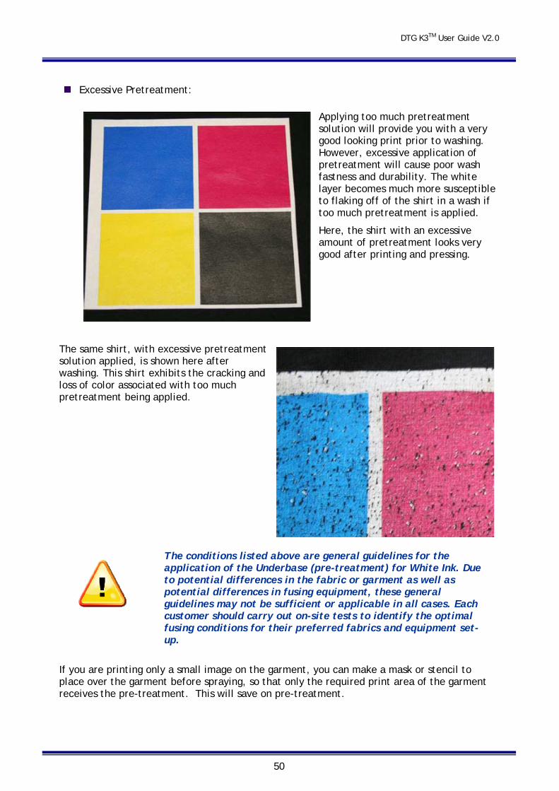
Excessive Pretreatment:
Applying too much pretreatment solution will provide you with a very good looking print prior to washing. However, excessive application of pretreatment will cause poor wash fastness and durability. The white layer becomes much more susceptible to flaking off of the shirt in a wash if too much pretreatment is applied.
Here, the shirt with an excessive amount of pretreatment looks very good after printing and pressing.
The same shirt, with excessive pretreatment solution applied, is shown here after washing. This shirt exhibits the cracking and loss of color associated with too much pretreatment being applied.
The conditions listed above are general guidelines for the application of the Underbase (pre-treatment) for White Ink. Due to potential differences in the fabric or garment as well as potential differences in fusing equipment, these general guidelines may not be sufficient or applicable in all cases. Each customer should carry out on-site tests to identify the optimal fusing conditions for their preferred fabrics and equipment set-up.
If you are printing only a small image on the garment, you can make a mask or stencil to place over the garment before spraying, so that only the required print area of the garment receives the pre-treatment. This will save on pre-treatment.
DTG K3TM User Guide V2.0
51
When printing white ink on lighter coloured garments (light blues, light greens, yellows, etc.) diluting the pre-treatment with water is recommended. A 50/50 solution with water will prevent any discolourisation of the lighter coloured garments. The coverage should be the same (10-15ml for an area of 14in x 17in).
It is a good idea to pre-treat all the garments for one job in a “batch”, and then move on to printing. Once a shirt is pre-treated it does not need to be printed immediately. This will make the production process smoother.
Light coloured garments where you are not planning to print any white ink generally do not require any pre-treatment process.
7.3 Load Garment to Platen / Platen to Printer
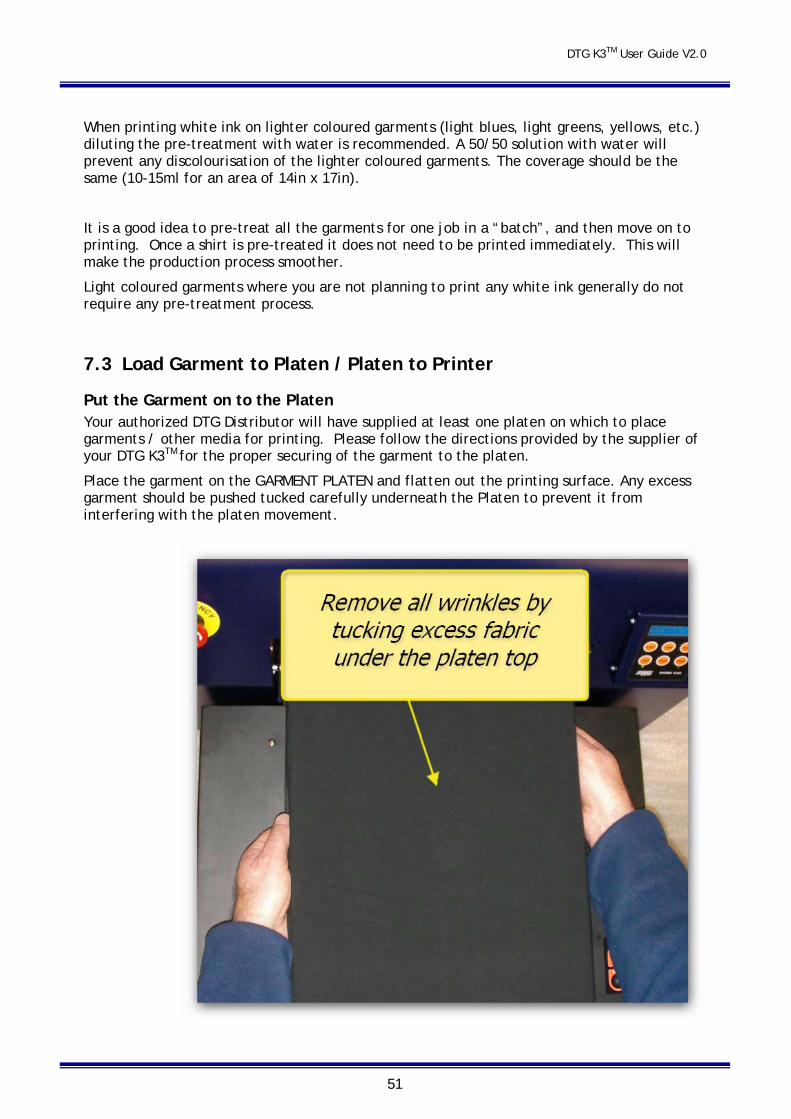
Put the Garment on to the Platen Your authorized DTG Distributor will have supplied at least one platen on which to place garments / other media for printing. Please follow the directions provided by the supplier of your DTG K3TM for the proper securing of the garment to the platen.
Place the garment on the GARMENT PLATEN and flatten out the printing surface. Any excess garment should be pushed tucked carefully underneath the Platen to prevent it from interfering with the platen movement.
DTG K3TM User Guide V2.0
52
Adjust Printing Bed Height / Move Platen to the Top of Page position Set the Platen (with garment(s) loaded) on to the Media Conveyor Belt.
Ensure the GAP is turned on by ensuring that the GAP light is not orange. The garment must sit just below the lower edge of the top blue case part. The printed image will appear out of focus if the garment is set too low or the Printing Bed is not level. Always make sure before you start printing that there are no wrinkles in the garment or seams sitting above the top of the sides of the Printing Bed.
Refer to Section 6.2 for detailed information.
The Printing Head must not hit the garment or the Platen or any other
foreign object during printing. If it lightly brushes the garment you will have to do a head cleaning before the next print. If it even lightly brushes against pre-treated fabric, the pre treat may seal the ink in the head, and you will need to immediately perform several head cleans – and potentially have to replace the Print Head with a new one. If it touches the Platen you will have to do a head alignment. If the Print Head hits the Platen or even the garment itself with some force, you may have to replace the Print Head with a new one.
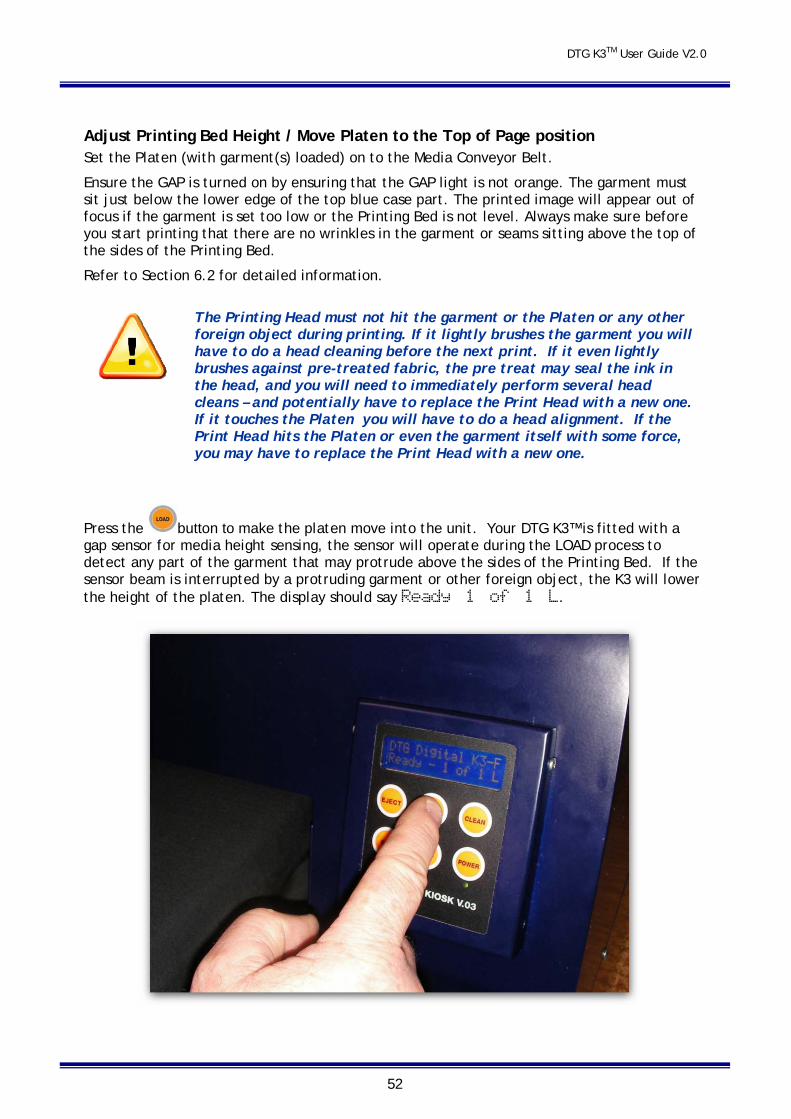
Press the button to make the platen move into the unit. Your DTG K3™ is fitted with a gap sensor for media height sensing, the sensor will operate during the LOAD process to detect any part of the garment that may protrude above the sides of the Printing Bed. If the sensor beam is interrupted by a protruding garment or other foreign object, the K3 will lower the height of the platen. The display should say Ready 1 of 1 L.
DTG K3TM User Guide V2.0
53
Print Your Image. Refer to the separate Quick Start guide and manual for your RIP.
After Printing Has Finished. After DTG K3™ has finished printing, the platen will automatically eject from the unit in the direction selected during the turn on process.
Further pull the platen out and remove the garment.
Checking PRINT QUALITY Print quality is an extremely important component of the printing process. You can check the print quality by doing a Nozzle Check from the Utility / Maintenance menu of the Epson R1900 driver (more information see page 39 of this manual). Be aware that you will need to do a Head Cleaning:
if any streaking appears in the print
if small drops of ink get on the garment during a printing cycle
if the unit has been sitting for a few days
if the printing head brushes the garment
To have DTG K3™ go through a head cleaning process, press the CLEAN button for four seconds. Severe head clogging may require you to do several head cleanings one after the other. You can perform a head cleaning while the unit is printing a job by simply holding down the CLEAN button for four seconds. You may have to clear lint from the bottom of the Print Head if you have printed a large quantity of garments with the setting so high that the printing head has brushed against the garments.
WARNING The head will automatically return to the capping station after 4 minutes. The LCD display will show the time remaining until this happens.
Removing INK SPOTS Remove any ink spots with a standard Spot Removal Gun before the print is heat cured. It is almost impossible to remove spots, stains or smudges once the ink has been heat cured. Be careful NOT to spray the wet print with the Spot remover or you will remove some of your image.
HEAT CURE Your Finished Print The final step is to heat cure your finished prints to completely set the ink. All prints should be cured either through a conveyor dryer or with a heat transfer press set at 335° F (170° C) for 120 seconds at 10psi. To check the temperature of your heat drying unit use an infrared heat gun. If using a conveyor dryer, run the belt speed very slow and make sure the garment lays flat on the belt.
The conditions listed above are general guidelines for the fusing of the DTGTex range of ink. Due to potential differences in the fabric or garment as well as potential differences in fusing equipment, these general guidelines may not be sufficient or applicable in all cases. Each customer should carry out on-site tests to identify the optimal fusing conditions for their preferred fabrics and equipment set-up.

DTG K3TM User Guide V2.0
54
You may have to use trial and error to perfect the curing process to ensure maximum binding of the ink pigments to the garment, without any heat damage to the garment.
WASHING Garments Garments printed with the DTG K3™ can be laundered as normal. It is a good idea to give your customer the following washing instructions:
Turn the garment inside out before washing and drying, use cold water only and a medium dryer temperature.
7.4 Cancelling a Print Job On rare occasions you may find you need to cancel a print in progress. Your RIP should have an option to cancel the print in progress. Refer to the User Guide for your RIP for further information.
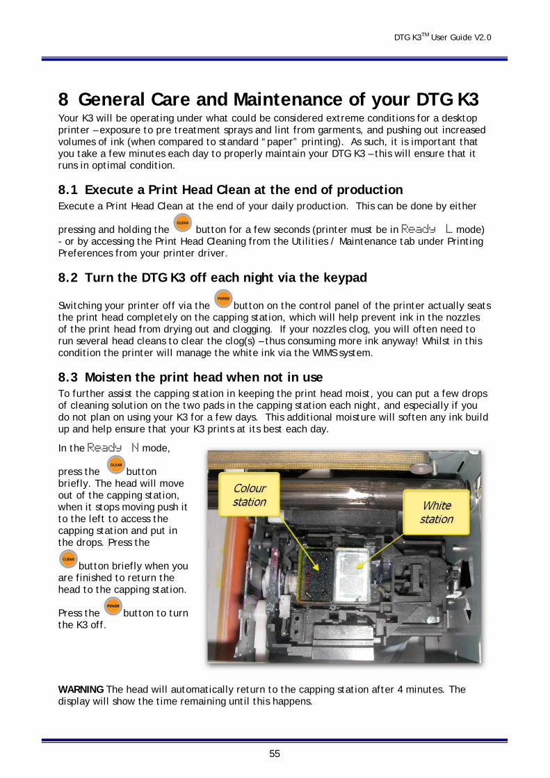
DTG K3TM User Guide V2.0
55
8 General Care and Maintenance of your DTG K3 Your K3 will be operating under what could be considered extreme conditions for a desktop printer – exposure to pre treatment sprays and lint from garments, and pushing out increased volumes of ink (when compared to standard “paper” printing). As such, it is important that you take a few minutes each day to properly maintain your DTG K3 – this will ensure that it runs in optimal condition.
8.1 Execute a Print Head Clean at the end of production Execute a Print Head Clean at the end of your daily production. This can be done by either
pressing and holding the button for a few seconds (printer must be in Ready L mode) - or by accessing the Print Head Cleaning from the Utilities / Maintenance tab under Printing Preferences from your printer driver.
8.2 Turn the DTG K3 off each night via the keypad
Switching your printer off via the button on the control panel of the printer actually seats the print head completely on the capping station, which will help prevent ink in the nozzles of the print head from drying out and clogging. If your nozzles clog, you will often need to run several head cleans to clear the clog(s) – thus consuming more ink anyway! Whilst in this condition the printer will manage the white ink via the WIMS system.
8.3 Moisten the print head when not in use To further assist the capping station in keeping the print head moist, you can put a few drops of cleaning solution on the two pads in the capping station each night, and especially if you do not plan on using your K3 for a few days. This additional moisture will soften any ink build up and help ensure that your K3 prints at its best each day.
In the Ready N mode,
press the button briefly. The head will move out of the capping station, when it stops moving push it to the left to access the capping station and put in the drops. Press the
button briefly when you are finished to return the head to the capping station.
Press the button to turn the K3 off.
WARNING The head will automatically return to the capping station after 4 minutes. The display will show the time remaining until this happens.
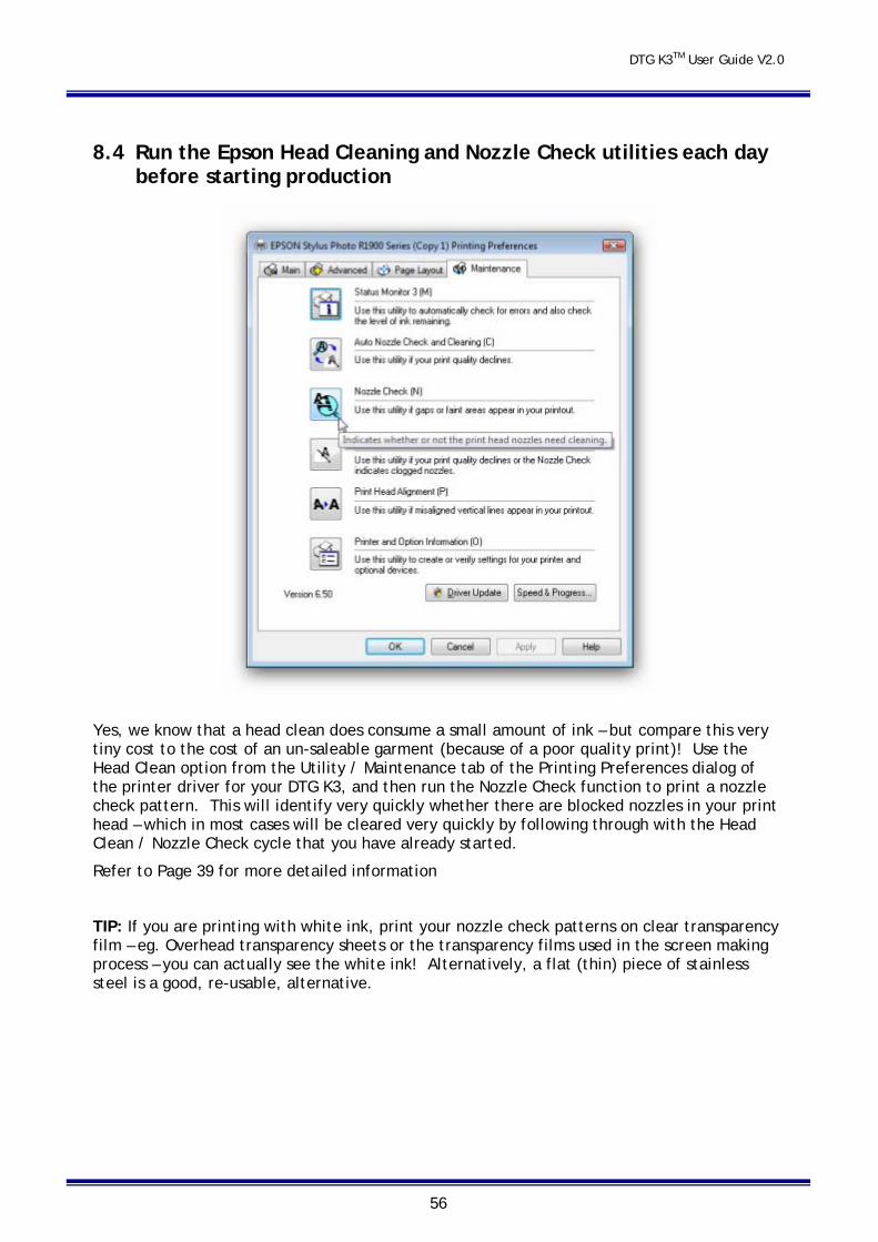
DTG K3TM User Guide V2.0
56
8.4 Run the Epson Head Cleaning and Nozzle Check utilities each day before starting production
Yes, we know that a head clean does consume a small amount of ink – but compare this very tiny cost to the cost of an un-saleable garment (because of a poor quality print)! Use the Head Clean option from the Utility / Maintenance tab of the Printing Preferences dialog of the printer driver for your DTG K3, and then run the Nozzle Check function to print a nozzle check pattern. This will identify very quickly whether there are blocked nozzles in your print head – which in most cases will be cleared very quickly by following through with the Head Clean / Nozzle Check cycle that you have already started.
Refer to Page 39 for more detailed information
TIP: If you are printing with white ink, print your nozzle check patterns on clear transparency film – eg. Overhead transparency sheets or the transparency films used in the screen making process – you can actually see the white ink! Alternatively, a flat (thin) piece of stainless steel is a good, re-usable, alternative.
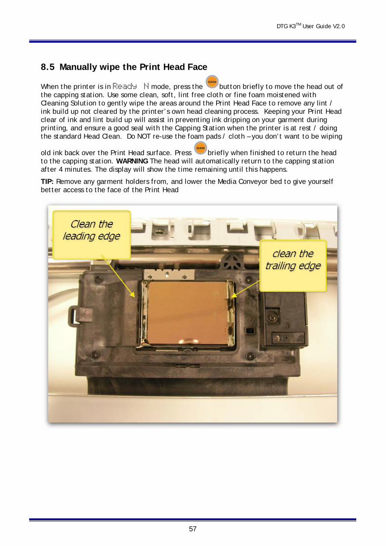
DTG K3TM User Guide V2.0
57
8.5 Manually wipe the Print Head Face
When the printer is in Ready N mode, press the button briefly to move the head out of the capping station. Use some clean, soft, lint free cloth or fine foam moistened with Cleaning Solution to gently wipe the areas around the Print Head Face to remove any lint / ink build up not cleared by the printer’s own head cleaning process. Keeping your Print Head clear of ink and lint build up will assist in preventing ink dripping on your garment during printing, and ensure a good seal with the Capping Station when the printer is at rest / doing the standard Head Clean. Do NOT re-use the foam pads / cloth – you don’t want to be wiping
old ink back over the Print Head surface. Press briefly when finished to return the head to the capping station. WARNING The head will automatically return to the capping station after 4 minutes. The display will show the time remaining until this happens.
TIP: Remove any garment holders from, and lower the Media Conveyor bed to give yourself better access to the face of the Print Head
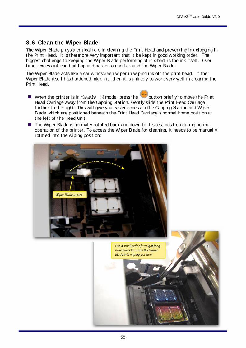
DTG K3TM User Guide V2.0
58
8.6 Clean the Wiper Blade The Wiper Blade plays a critical role in cleaning the Print Head and preventing ink clogging in the Print Head. It is therefore very important that it be kept in good working order. The biggest challenge to keeping the Wiper Blade performing at it’s best is the ink itself. Over time, excess ink can build up and harden on and around the Wiper Blade.
The Wiper Blade acts like a car windscreen wiper in wiping ink off the print head. If the Wiper Blade itself has hardened ink on it, then it is unlikely to work very well in cleaning the Print Head.
When the printer is in Ready N mode, press the button briefly to move the Print Head Carriage away from the Capping Station. Gently slide the Print Head Carriage further to the right. This will give you easier access to the Capping Station and Wiper Blade which are positioned beneath the Print Head Carriage’s normal home position at the left of the Head Unit.
The Wiper Blade is normally rotated back and down to it’s rest position during normal operation of the printer. To access the Wiper Blade for cleaning, it needs to be manually rotated into the wiping position:
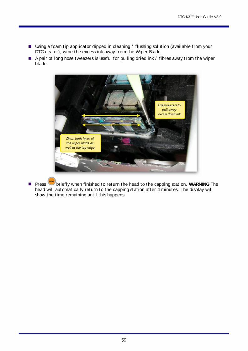
DTG K3TM User Guide V2.0
59
Using a foam tip applicator dipped in cleaning / flushing solution (available from your
DTG dealer), wipe the excess ink away from the Wiper Blade. A pair of long nose tweezers is useful for pulling dried ink / fibres away from the wiper
blade.
Press briefly when finished to return the head to the capping station. WARNING The head will automatically return to the capping station after 4 minutes. The display will show the time remaining until this happens.
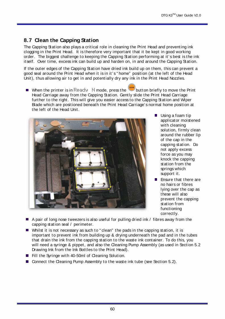
DTG K3TM User Guide V2.0
60
8.7 Clean the Capping Station The Capping Station also plays a critical role in cleaning the Print Head and preventing ink clogging in the Print Head. It is therefore very important that it be kept in good working order. The biggest challenge to keeping the Capping Station performing at it’s best is the ink itself. Over time, excess ink can build up and harden on, in and around the Capping Station.
If the outer edges of the Capping Station have dried ink build up on them, this can prevent a good seal around the Print Head when it is in it’s “home” position (at the left of the Head Unit), thus allowing air to get in and potentially dry any ink in the Print Head Nozzles.
When the printer is in Ready N mode, press the button briefly to move the Print Head Carriage away from the Capping Station. Gently slide the Print Head Carriage further to the right. This will give you easier access to the Capping Station and Wiper Blade which are positioned beneath the Print Head Carriage’s normal home position at the left of the Head Unit.
Using a foam tip applicator moistened with cleaning solution, firmly clean around the rubber lip of the cap in the capping station. Do not apply excess force as you may knock the capping station from the springs which support it.
Ensure that there are no hairs or fibres lying over the cap as these will also prevent the capping station from functioning correctly.
A pair of long nose tweezers is also useful for pulling dried ink / fibres away from the capping station seal / perimeter.
Whilst it is not necessary as such to “clean” the pads in the capping station, it is important to prevent ink from building up & drying underneath the pad and in the tubes that drain the ink from the capping station to the waste ink container. To do this, you will need a syringe & pippet, and also the Cleaning Pump Assembly (as used in Section 5.2 Drawing Ink from the Ink Bottles to the Print Head).
Fill the Syringe with 40-50ml of Cleaning Solution. Connect the Cleaning Pump Assembly to the waste ink tube (see Section 5.2).
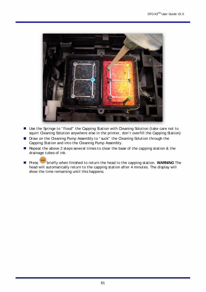
DTG K3TM User Guide V2.0
61
Use the Syringe to “flood” the Capping Station with Cleaning Solution (take care not to squirt Cleaning Solution anywhere else in the printer, don’t overfill the Capping Station)
Draw on the Cleaning Pump Assembly to “suck” the Cleaning Solution through the Capping Station and into the Cleaning Pump Assembly.
Repeat the above 2 steps several times to clear the base of the capping station & the drainage tubes of ink.
Press briefly when finished to return the head to the capping station. WARNING The head will automatically return to the capping station after 4 minutes. The display will show the time remaining until this happens.
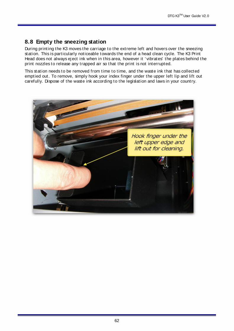
DTG K3TM User Guide V2.0
62
8.8 Empty the sneezing station During printing the K3 moves the carriage to the extreme left and hovers over the sneezing station. This is particularly noticeable towards the end of a head clean cycle. The K3 Print Head does not always eject ink when in this area, however it ‘vibrates’ the plates behind the print nozzles to release any trapped air so that the print is not interrupted.
This station needs to be removed from time to time, and the waste ink that has collected emptied out. To remove, simply hook your index finger under the upper left lip and lift out carefully. Dispose of the waste ink according to the legislation and laws in your country.
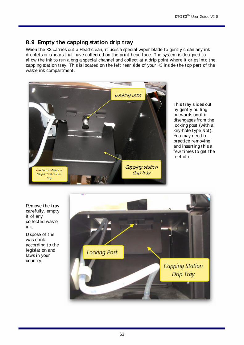
DTG K3TM User Guide V2.0
63
8.9 Empty the capping station drip tray When the K3 carries out a Head clean, it uses a special wiper blade to gently clean any ink droplets or smears that have collected on the print head face. The system is designed to allow the ink to run along a special channel and collect at a drip point where it drips into the capping station tray. This is located on the left rear side of your K3 inside the top part of the waste ink compartment.
This tray slides out by gently pulling outwards until it disengages from the locking post (with a key-hole type slot). You may need to practice removing and inserting this a few times to get the feel of it.
Remove the tray carefully, empty it of any collected waste ink.
Dispose of the waste ink according to the legislation and laws in your country.
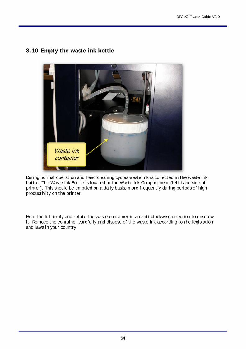
DTG K3TM User Guide V2.0
64
8.10 Empty the waste ink bottle
During normal operation and head cleaning cycles waste ink is collected in the waste ink bottle. The Waste Ink Bottle is located in the Waste Ink Compartment (left hand side of printer). This should be emptied on a daily basis, more frequently during periods of high productivity on the printer.
Hold the lid firmly and rotate the waste container in an anti-clockwise direction to unscrew it. Remove the container carefully and dispose of the waste ink according to the legislation and laws in your country.
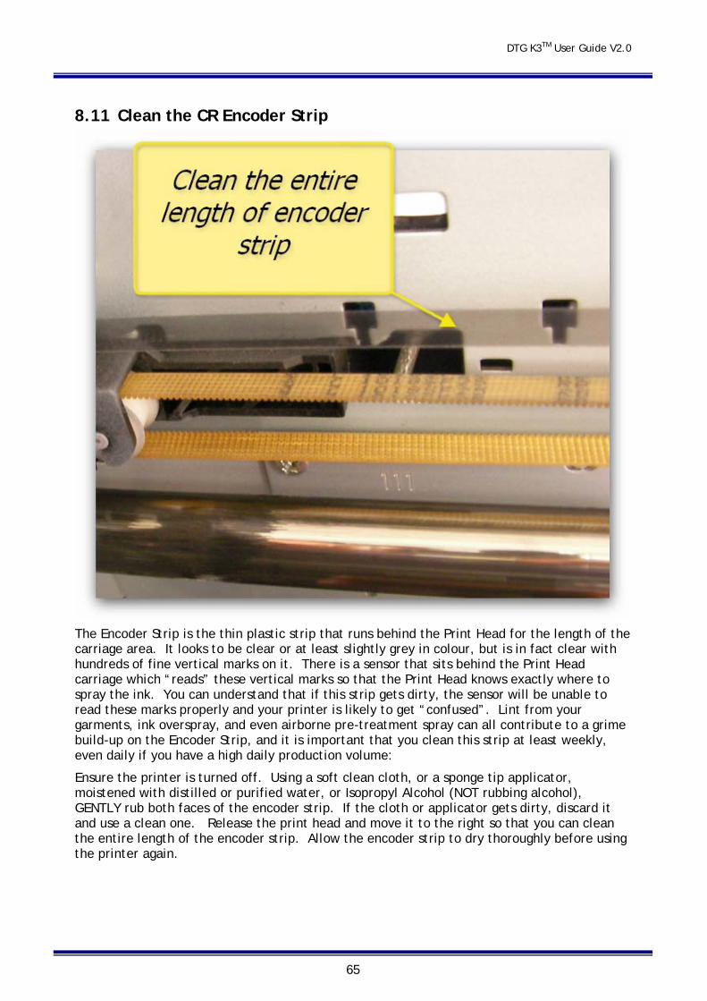
DTG K3TM User Guide V2.0
65
8.11 Clean the CR Encoder Strip
The Encoder Strip is the thin plastic strip that runs behind the Print Head for the length of the carriage area. It looks to be clear or at least slightly grey in colour, but is in fact clear with hundreds of fine vertical marks on it. There is a sensor that sits behind the Print Head carriage which “reads” these vertical marks so that the Print Head knows exactly where to spray the ink. You can understand that if this strip gets dirty, the sensor will be unable to read these marks properly and your printer is likely to get “confused”. Lint from your garments, ink overspray, and even airborne pre-treatment spray can all contribute to a grime build-up on the Encoder Strip, and it is important that you clean this strip at least weekly, even daily if you have a high daily production volume:
Ensure the printer is turned off. Using a soft clean cloth, or a sponge tip applicator, moistened with distilled or purified water, or Isopropyl Alcohol (NOT rubbing alcohol), GENTLY rub both faces of the encoder strip. If the cloth or applicator gets dirty, discard it and use a clean one. Release the print head and move it to the right so that you can clean the entire length of the encoder strip. Allow the encoder strip to dry thoroughly before using the printer again.
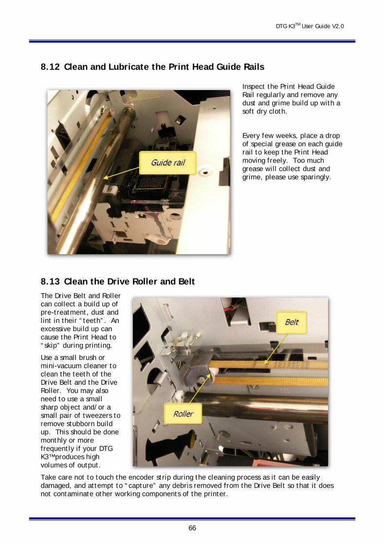
DTG K3TM User Guide V2.0
66
8.12 Clean and Lubricate the Print Head Guide Rails
Inspect the Print Head Guide Rail regularly and remove any dust and grime build up with a soft dry cloth.
Every few weeks, place a drop of special grease on each guide rail to keep the Print Head moving freely. Too much grease will collect dust and grime, please use sparingly.
8.13 Clean the Drive Roller and Belt The Drive Belt and Roller can collect a build up of pre-treatment, dust and lint in their “teeth”. An excessive build up can cause the Print Head to “skip” during printing.
Use a small brush or mini-vacuum cleaner to clean the teeth of the Drive Belt and the Drive Roller. You may also need to use a small sharp object and/or a small pair of tweezers to remove stubborn build up. This should be done monthly or more frequently if your DTG K3™ produces high volumes of output.
Take care not to touch the encoder strip during the cleaning process as it can be easily damaged, and attempt to “capture” any debris removed from the Drive Belt so that it does not contaminate other working components of the printer.
DTG K3TM User Guide V2.0
67
8.14 Environmental Conditions It is important to maintain consistent environmental conditions so that your DTG K3 can run at its best. Inkjet printers like humidity levels of 40 – 70%. They do not like extremes in temperature, so it is best to operate your DTG K3 in an air conditioned environment – but not such that fans are blowing directly across the printer (and therefore the print head which may dry the ink in the print head itself). As the ink needs to be stored at no less than 5° Celsius (41°F) and no more than 30° Celsius (86°F), this is also the recommended operating and storage temperature range for your DTG K3™.
Dust is also an enemy of the DTG K3 (and in fact any ink-jet printer). The working environment should be relatively dust free.
8.15 Clean your DTG K3™ Lint, dust and pre-treatment overspray can build up and interfere with not only the “internal” workings of the printer, but also the operation of the printer bed. Turn the printer off and clean all accessible surfaces of the printer with glass cleaner and a soft cloth (do not spray the cleaner directly onto the printer, rather onto the cloth) to remove dust and grime build up.
8.16 Cover your DTG K3™ We recommend that you cover your DTG K3 when it is not in use – use a small (clean) tarpaulin or similar, to help prevent dust from entering the carriage area of the printer and to help prevent the print head from drying out.
8.17 Avoid White Ink Separation As explained earlier in this User Guide, by it’s very nature, white ink (of any brand) is prone to “separation”, i.e. the separation of the pigment (the bits that give the white ink it’s opacity) from the binder (the bits that bind the pigment to your garments). If you do not print from your printer every day, you should at least turn it on and execute a head clean on
a daily basis (press and hold button for a few seconds when the printer is in Ready L mode) to keep the ink moving through the system. It is recommended that you also run a white ink print from your printer each day.
You must also gently shake any white ink bottles that you have in stock in order to maximize the shelf life of the white ink.
After several days of non-use, you may find that the white ink has separated in the Print Head to the point that when you print the white underbase of your first print, it comes out very translucent. You can either “print” this out by printing a large white square, or run 1-2 head cleanings from the Utilities / Maintenance tab under Printing Preferences from the printer driver.
8.18 Ink Levels It is recommended that you keep your ink bottles (particularly the white ink) ½ to ¾ full at all times.
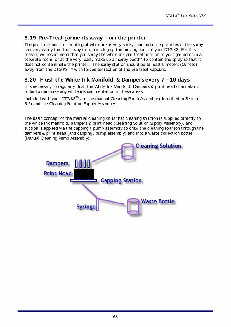
DTG K3TM User Guide V2.0
68
8.19 Pre-Treat garments away from the printer The pre-treatment for printing of white ink is very sticky, and airborne particles of the spray can very easily find their way into, and clog up the moving parts of your DTG K3. For this reason, we recommend that you spray the white ink pre-treatment on to your garments in a separate room, or at the very least, make up a “spray booth” to contain the spray so that it does not contaminate the printer. The spray station should be at least 5 meters (15 feet) away from the DTG K3 ™, with forced extraction of the pre treat vapours.
8.20 Flush the White Ink Manifold & Dampers every 7 – 10 days It is necessary to regularly flush the White Ink Manifold, Dampers & print head channels in order to minimize any white ink sedimentation in these areas.
Included with your DTG K3TM are the manual Cleaning Pump Assembly (described in Section 5.2) and the Cleaning Solution Supply Assembly.
The basic concept of the manual cleaning kit is that cleaning solution is supplied directly to the white ink manifold, dampers & print head (Cleaning Solution Supply Assembly), and suction is applied via the capping / pump assembly to draw the cleaning solution through the dampers & print head (and capping /pump assembly) and into a waste collection bottle (Manual Cleaning Pump Assembly).
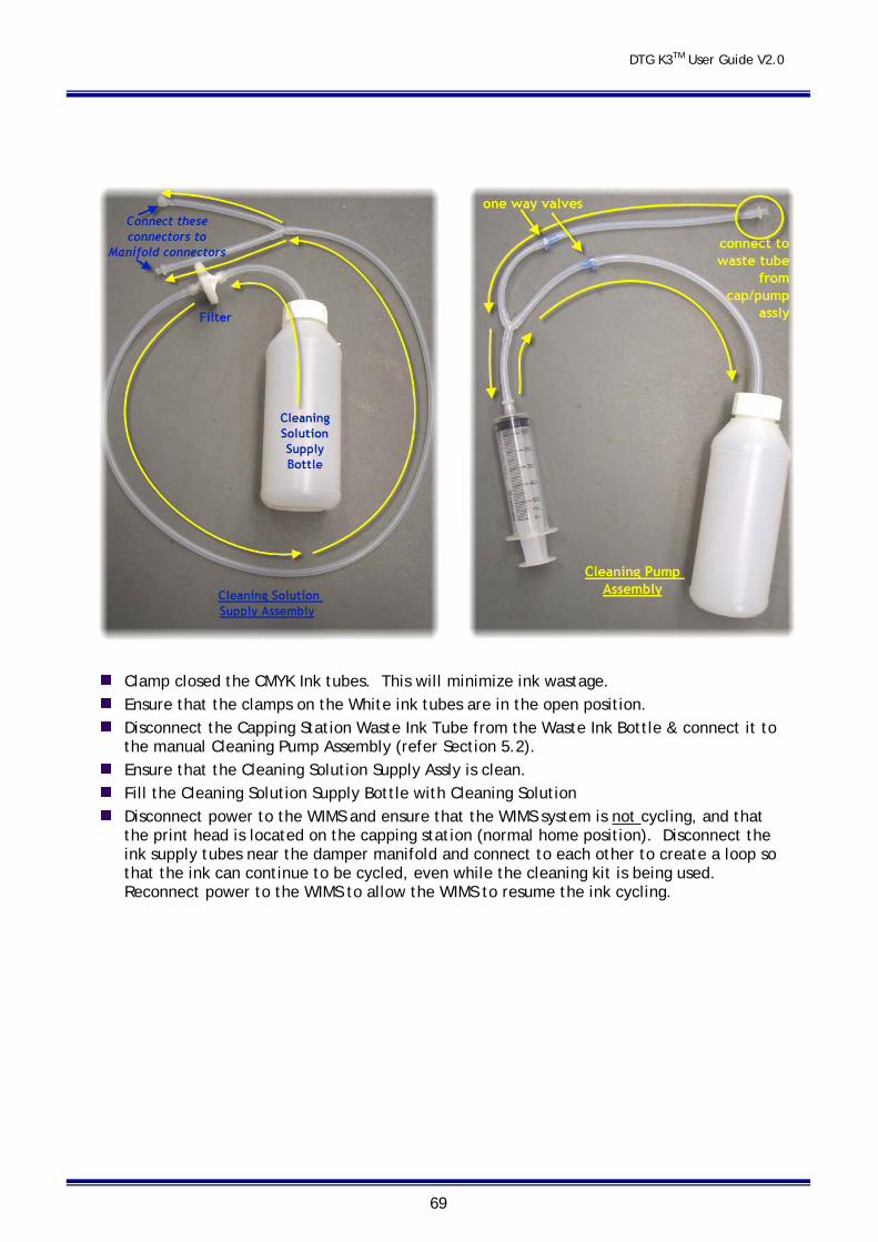
DTG K3TM User Guide V2.0
69
Clamp closed the CMYK Ink tubes. This will minimize ink wastage. Ensure that the clamps on the White ink tubes are in the open position. Disconnect the Capping Station Waste Ink Tube from the Waste Ink Bottle & connect it to
the manual Cleaning Pump Assembly (refer Section 5.2). Ensure that the Cleaning Solution Supply Assly is clean. Fill the Cleaning Solution Supply Bottle with Cleaning Solution Disconnect power to the WIMS and ensure that the WIMS system is not cycling, and that
the print head is located on the capping station (normal home position). Disconnect the ink supply tubes near the damper manifold and connect to each other to create a loop so that the ink can continue to be cycled, even while the cleaning kit is being used. Reconnect power to the WIMS to allow the WIMS to resume the ink cycling.
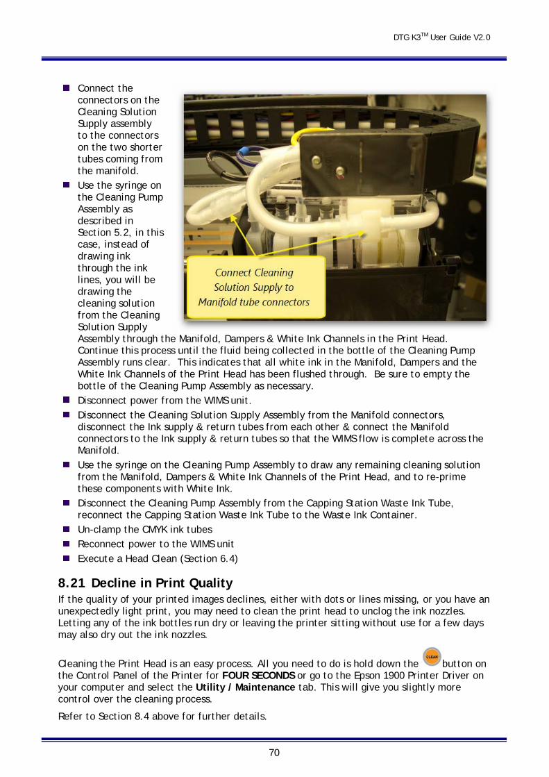
DTG K3TM User Guide V2.0
70
Connect the connectors on the Cleaning Solution Supply assembly to the connectors on the two shorter tubes coming from the manifold.
Use the syringe on the Cleaning Pump Assembly as described in Section 5.2, in this case, instead of drawing ink through the ink lines, you will be drawing the cleaning solution from the Cleaning Solution Supply Assembly through the Manifold, Dampers & White Ink Channels in the Print Head. Continue this process until the fluid being collected in the bottle of the Cleaning Pump Assembly runs clear. This indicates that all white ink in the Manifold, Dampers and the White Ink Channels of the Print Head has been flushed through. Be sure to empty the bottle of the Cleaning Pump Assembly as necessary.
Disconnect power from the WIMS unit. Disconnect the Cleaning Solution Supply Assembly from the Manifold connectors,
disconnect the Ink supply & return tubes from each other & connect the Manifold connectors to the Ink supply & return tubes so that the WIMS flow is complete across the Manifold.
Use the syringe on the Cleaning Pump Assembly to draw any remaining cleaning solution from the Manifold, Dampers & White Ink Channels of the Print Head, and to re-prime these components with White Ink.
Disconnect the Cleaning Pump Assembly from the Capping Station Waste Ink Tube, reconnect the Capping Station Waste Ink Tube to the Waste Ink Container.
Un-clamp the CMYK ink tubes Reconnect power to the WIMS unit Execute a Head Clean (Section 6.4)
8.21 Decline in Print Quality If the quality of your printed images declines, either with dots or lines missing, or you have an unexpectedly light print, you may need to clean the print head to unclog the ink nozzles. Letting any of the ink bottles run dry or leaving the printer sitting without use for a few days may also dry out the ink nozzles.
Cleaning the Print Head is an easy process. All you need to do is hold down the button on the Control Panel of the Printer for FOUR SECONDS or go to the Epson 1900 Printer Driver on your computer and select the Utility / Maintenance tab. This will give you slightly more control over the cleaning process.
Refer to Section 8.4 above for further details.
DTG K3TM User Guide V2.0
71
Please Note: Never turn off the printer while the power light is flashing as this may damage the printer.
Please Note: It is possible to do a head cleaning at any time even when the printer is printing. Printing will stop while it cleans the heads and resume where it stopped when cleaning is finished.
Please Note: It is recommended that you do a head cleaning if you see any drops of ink on the garments you are printing or if the Print Head comes in contact with the garment – the cleaning process will also clean the bottom of the Print Head.
8.22 Aligning the Print Head WARNING – DO NOT CARRY OUT ANY AUTOMATIC ADJUSTMENTS FROM THE MENU
If you notice any vertical or misaligned lines on your prints, or banding of any kind, you will need to do a Print Head Alignment. There are several ways in which the Print Head may become misaligned – it could simply be through normal use, or if the Print Head hits a garment or the metal Holding Ring during printing, or during transportation of the unit. If the Print Head has hit hard on a garment, on the Metal Holding Ring or any other hard surface it may be permanently damaged or misaligned and will need to be replaced.
In order to best align the print heads, you must firstly make sure that you have a “clean” Print Head – a good Nozzle Check Pattern is a good indication of this (see Section 8.4 above).
Follow the directions below to carry out a basic Print Head Alignment:
Turn the printer ON.
Place an A4 or A3 size sheet of clear film / stainless steel on top of the Garment Platen so that it butts up to the top left corner of the Platen. You may have to tape the film into place if it curls as it needs to be flat. Load the Platen.
Go to the Maintenance Tab of the Printing Preferences dialog (from the Printer Driver User Interface), Select Print Head Alignment
Click on the MANUAL button to select the next step DO NOT SELECT AUTOMATIC.
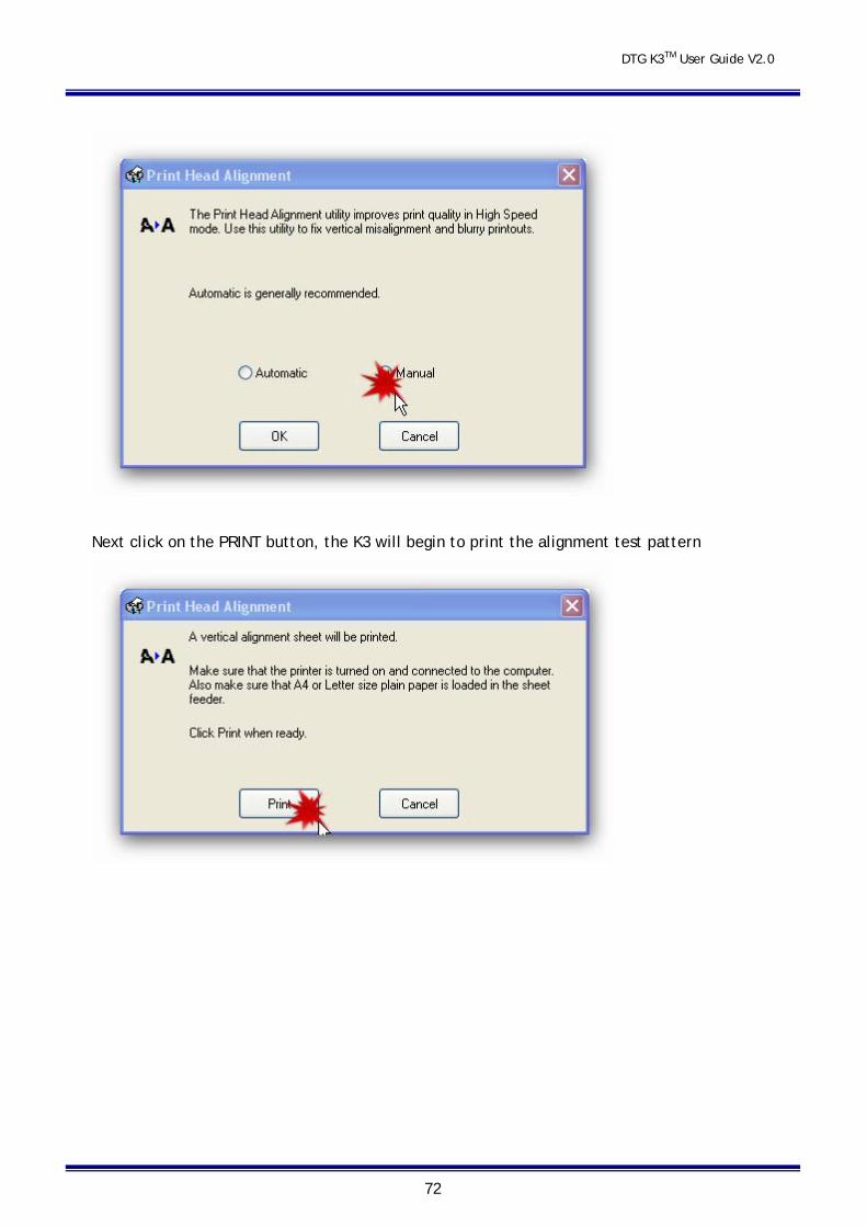
DTG K3TM User Guide V2.0
72
Next click on the PRINT button, the K3 will begin to print the alignment test pattern
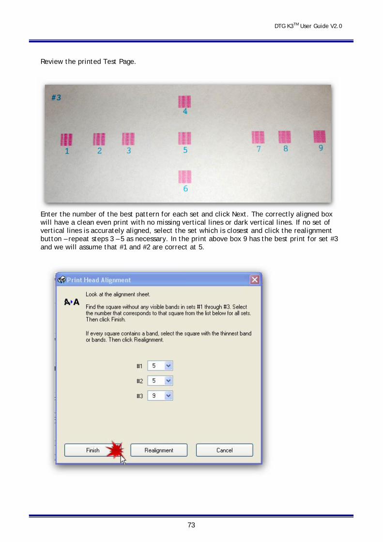
DTG K3TM User Guide V2.0
73
Review the printed Test Page.
Enter the number of the best pattern for each set and click Next. The correctly aligned box will have a clean even print with no missing vertical lines or dark vertical lines. If no set of vertical lines is accurately aligned, select the set which is closest and click the realignment button – repeat steps 3 – 5 as necessary. In the print above box 9 has the best print for set #3 and we will assume that #1 and #2 are correct at 5.
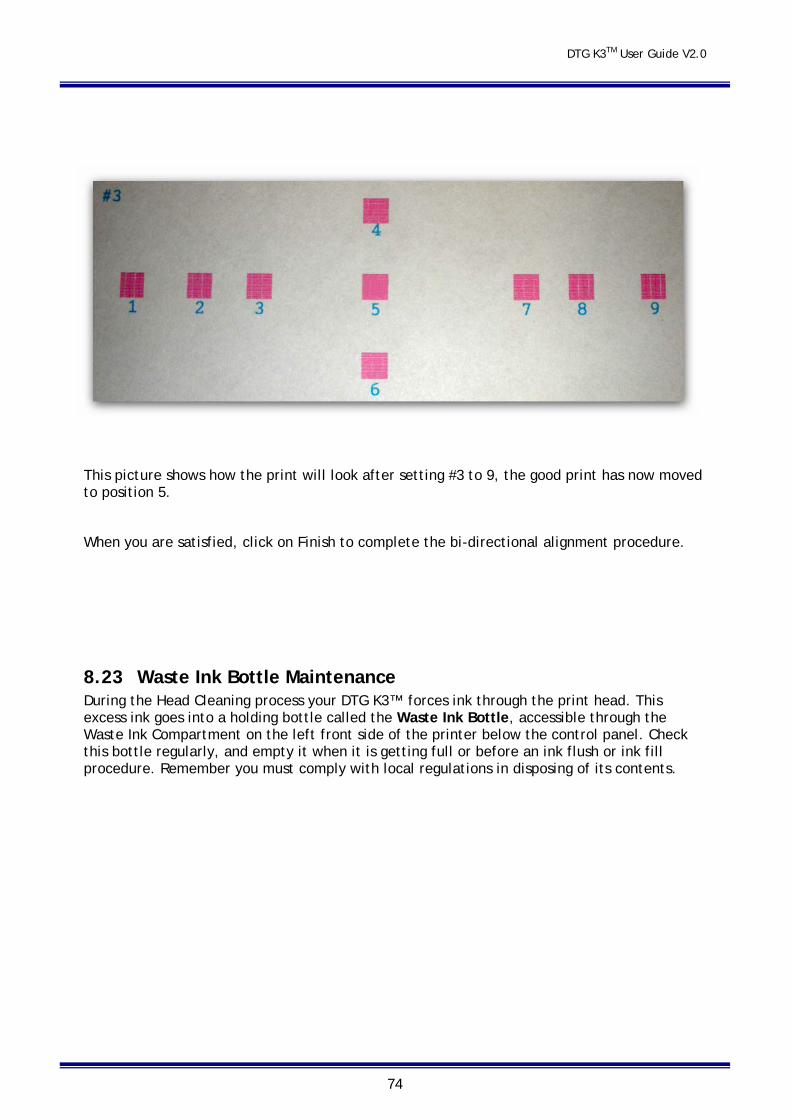
DTG K3TM User Guide V2.0
74
This picture shows how the print will look after setting #3 to 9, the good print has now moved to position 5.
When you are satisfied, click on Finish to complete the bi-directional alignment procedure.
8.23 Waste Ink Bottle Maintenance During the Head Cleaning process your DTG K3™ forces ink through the print head. This excess ink goes into a holding bottle called the Waste Ink Bottle, accessible through the Waste Ink Compartment on the left front side of the printer below the control panel. Check this bottle regularly, and empty it when it is getting full or before an ink flush or ink fill procedure. Remember you must comply with local regulations in disposing of its contents.
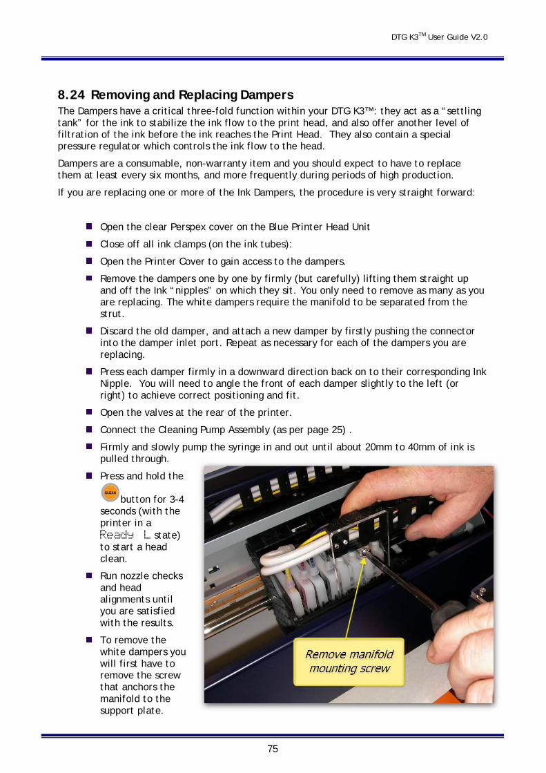
DTG K3TM User Guide V2.0
75
8.24 Removing and Replacing Dampers The Dampers have a critical three-fold function within your DTG K3™ : they act as a “settling tank” for the ink to stabilize the ink flow to the print head, and also offer another level of filtration of the ink before the ink reaches the Print Head. They also contain a special pressure regulator which controls the ink flow to the head.
Dampers are a consumable, non-warranty item and you should expect to have to replace them at least every six months, and more frequently during periods of high production.
If you are replacing one or more of the Ink Dampers, the procedure is very straight forward:
Open the clear Perspex cover on the Blue Printer Head Unit
Close off all ink clamps (on the ink tubes):
Open the Printer Cover to gain access to the dampers.
Remove the dampers one by one by firmly (but carefully) lifting them straight up and off the Ink “nipples” on which they sit. You only need to remove as many as you are replacing. The white dampers require the manifold to be separated from the strut.
Discard the old damper, and attach a new damper by firstly pushing the connector into the damper inlet port. Repeat as necessary for each of the dampers you are replacing.
Press each damper firmly in a downward direction back on to their corresponding Ink Nipple. You will need to angle the front of each damper slightly to the left (or right) to achieve correct positioning and fit.
Open the valves at the rear of the printer.
Connect the Cleaning Pump Assembly (as per page 25) .
Firmly and slowly pump the syringe in and out until about 20mm to 40mm of ink is pulled through.
Press and hold the
button for 3-4 seconds (with the printer in a Ready L state) to start a head clean.
Run nozzle checks and head alignments until you are satisfied with the results.
To remove the white dampers you will first have to remove the screw that anchors the manifold to the support plate.
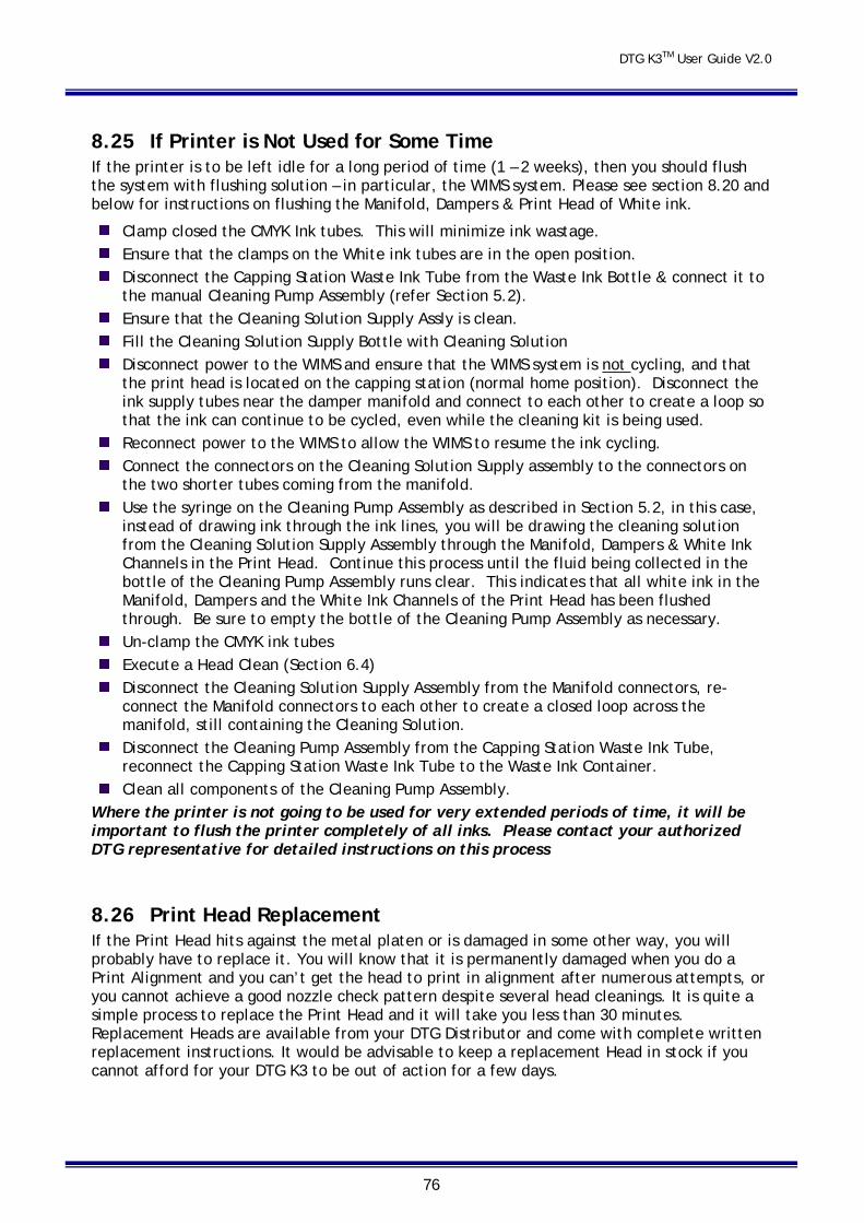
DTG K3TM User Guide V2.0
76
8.25 If Printer is Not Used for Some Time If the printer is to be left idle for a long period of time (1 – 2 weeks), then you should flush the system with flushing solution – in particular, the WIMS system. Please see section 8.20 and below for instructions on flushing the Manifold, Dampers & Print Head of White ink.
Clamp closed the CMYK Ink tubes. This will minimize ink wastage. Ensure that the clamps on the White ink tubes are in the open position. Disconnect the Capping Station Waste Ink Tube from the Waste Ink Bottle & connect it to
the manual Cleaning Pump Assembly (refer Section 5.2). Ensure that the Cleaning Solution Supply Assly is clean. Fill the Cleaning Solution Supply Bottle with Cleaning Solution Disconnect power to the WIMS and ensure that the WIMS system is not cycling, and that
the print head is located on the capping station (normal home position). Disconnect the ink supply tubes near the damper manifold and connect to each other to create a loop so that the ink can continue to be cycled, even while the cleaning kit is being used.
Reconnect power to the WIMS to allow the WIMS to resume the ink cycling. Connect the connectors on the Cleaning Solution Supply assembly to the connectors on
the two shorter tubes coming from the manifold. Use the syringe on the Cleaning Pump Assembly as described in Section 5.2, in this case,
instead of drawing ink through the ink lines, you will be drawing the cleaning solution from the Cleaning Solution Supply Assembly through the Manifold, Dampers & White Ink Channels in the Print Head. Continue this process until the fluid being collected in the bottle of the Cleaning Pump Assembly runs clear. This indicates that all white ink in the Manifold, Dampers and the White Ink Channels of the Print Head has been flushed through. Be sure to empty the bottle of the Cleaning Pump Assembly as necessary.
Un-clamp the CMYK ink tubes Execute a Head Clean (Section 6.4) Disconnect the Cleaning Solution Supply Assembly from the Manifold connectors, re-
connect the Manifold connectors to each other to create a closed loop across the manifold, still containing the Cleaning Solution.
Disconnect the Cleaning Pump Assembly from the Capping Station Waste Ink Tube, reconnect the Capping Station Waste Ink Tube to the Waste Ink Container.
Clean all components of the Cleaning Pump Assembly. Where the printer is not going to be used for very extended periods of time, it will be important to flush the printer completely of all inks. Please contact your authorized DTG representative for detailed instructions on this process
8.26 Print Head Replacement If the Print Head hits against the metal platen or is damaged in some other way, you will probably have to replace it. You will know that it is permanently damaged when you do a Print Alignment and you can’t get the head to print in alignment after numerous attempts, or you cannot achieve a good nozzle check pattern despite several head cleanings. It is quite a simple process to replace the Print Head and it will take you less than 30 minutes. Replacement Heads are available from your DTG Distributor and come with complete written replacement instructions. It would be advisable to keep a replacement Head in stock if you cannot afford for your DTG K3 to be out of action for a few days.
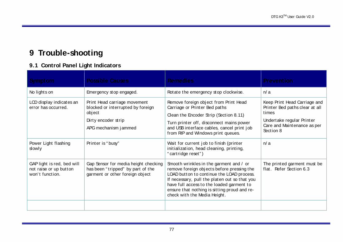
DTG K3TM User Guide V2.0
77
9 Trouble-shooting 9.1 Control Panel Light Indicators
Symptom Possible Causes Remedies Prevention
No lights on Emergency stop engaged. Rotate the emergency stop clockwise. n/a
LCD display indicates an error has occurred.
Print Head carriage movement blocked or interrupted by foreign object
Dirty encoder strip
APG mechanism jammed
Remove foreign object from Print Head Carriage or Printer Bed paths
Clean the Encoder Strip (Section 8.11)
Turn printer off, disconnect mains power and USB interface cables, cancel print job from RIP and Windows print queues.
Keep Print Head Carriage and Printer Bed paths clear at all times
Undertake regular Printer Care and Maintenance as per Section 8
Power Light flashing slowly
Printer is “busy” Wait for current job to finish (printer initialization, head cleaning, printing, “cartridge reset”)
n/a
GAP light is red, bed will not raise or up button won’t function.
Gap Sensor for media height checking has been “tripped” by part of the garment or other foreign object
Smooth wrinkles in the garment and / or remove foreign objects before pressing the LOAD button to continue the LOAD process. If necessary, pull the platen out so that you have full access to the loaded garment to ensure that nothing is sitting proud and re-check with the Media Height.
The printed garment must be flat. Refer Section 6.3
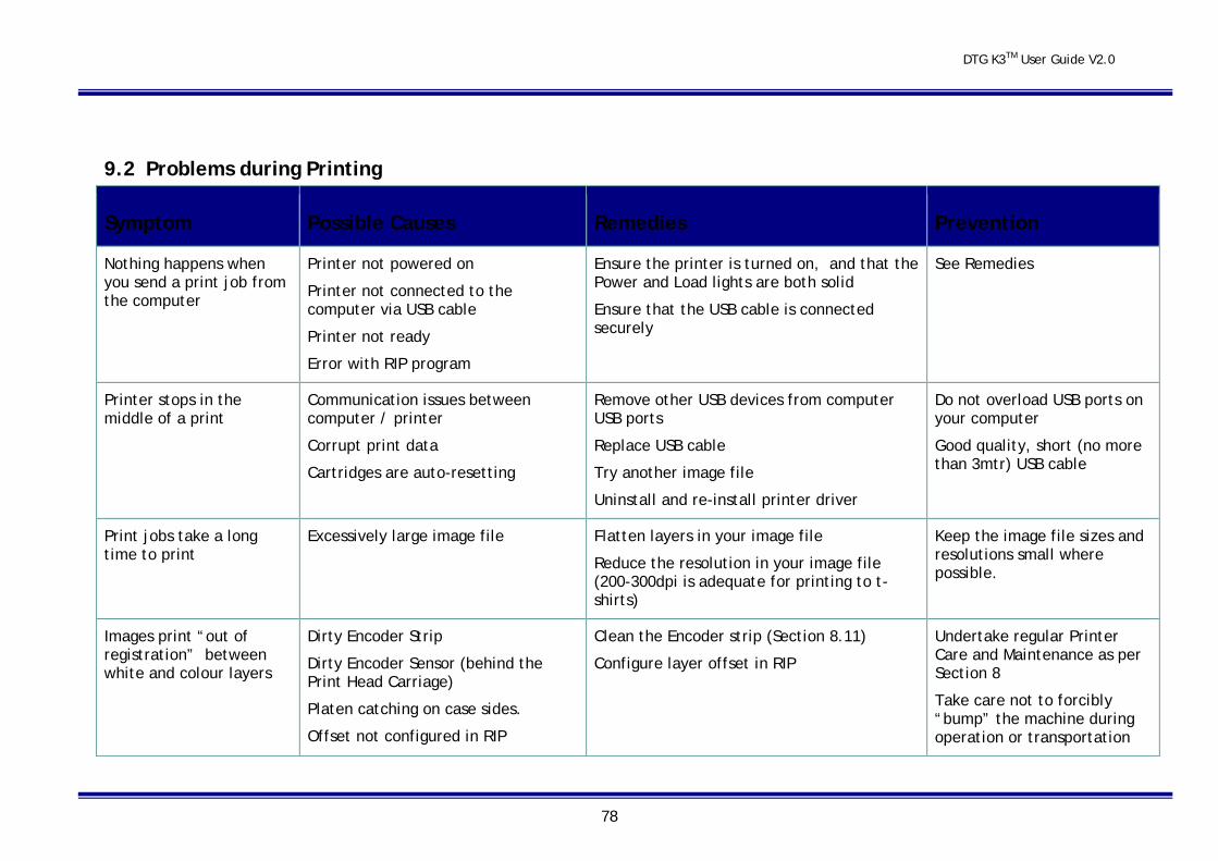
DTG K3TM User Guide V2.0
78
9.2 Problems during Printing
Symptom Possible Causes Remedies Prevention
Nothing happens when you send a print job from the computer
Printer not powered on
Printer not connected to the computer via USB cable
Printer not ready
Error with RIP program
Ensure the printer is turned on, and that the Power and Load lights are both solid
Ensure that the USB cable is connected securely
See Remedies
Printer stops in the middle of a print
Communication issues between computer / printer
Corrupt print data
Cartridges are auto-resetting
Remove other USB devices from computer USB ports
Replace USB cable
Try another image file
Uninstall and re-install printer driver
Do not overload USB ports on your computer
Good quality, short (no more than 3mtr) USB cable
Print jobs take a long time to print
Excessively large image file
Flatten layers in your image file
Reduce the resolution in your image file (200-300dpi is adequate for printing to t-shirts)
Keep the image file sizes and resolutions small where possible.
Images print “out of registration” between white and colour layers
Dirty Encoder Strip
Dirty Encoder Sensor (behind the Print Head Carriage)
Platen catching on case sides.
Offset not configured in RIP
Clean the Encoder strip (Section 8.11)
Configure layer offset in RIP
Undertake regular Printer Care and Maintenance as per Section 8
Take care not to forcibly “bump” the machine during operation or transportation
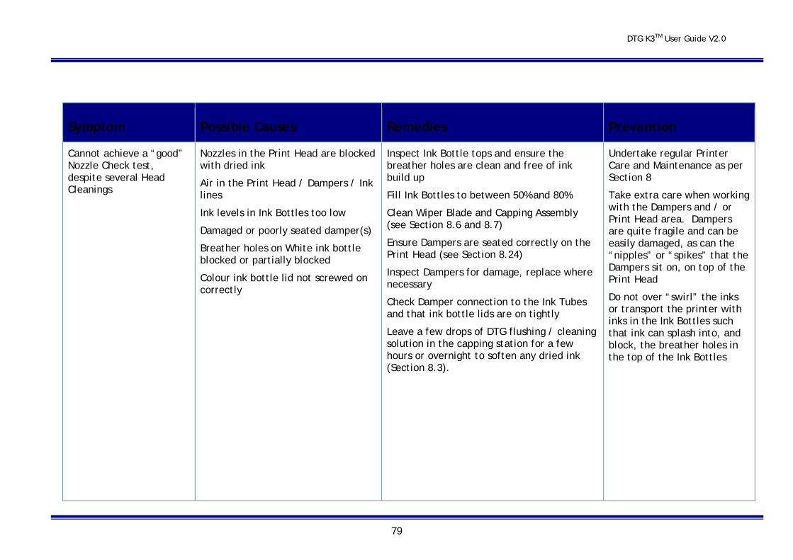
DTG K3TM User Guide V2.0
79
Symptom Possible Causes Remedies Prevention
Cannot achieve a “good” Nozzle Check test, despite several Head Cleanings
Nozzles in the Print Head are blocked with dried ink
Air in the Print Head / Dampers / Ink lines
Ink levels in Ink Bottles too low
Damaged or poorly seated damper(s)
Breather holes on White ink bottle blocked or partially blocked
Colour ink bottle lid not screwed on correctly
Inspect Ink Bottle tops and ensure the breather holes are clean and free of ink build up
Fill Ink Bottles to between 50% and 80%
Clean Wiper Blade and Capping Assembly (see Section 8.6 and 8.7)
Ensure Dampers are seated correctly on the Print Head (see Section 8.24)
Inspect Dampers for damage, replace where necessary
Check Damper connection to the Ink Tubes and that ink bottle lids are on tightly
Leave a few drops of DTG flushing / cleaning solution in the capping station for a few hours or overnight to soften any dried ink (Section 8.3).
Undertake regular Printer Care and Maintenance as per Section 8
Take extra care when working with the Dampers and / or Print Head area. Dampers are quite fragile and can be easily damaged, as can the “nipples” or “spikes” that the Dampers sit on, on top of the Print Head
Do not over “swirl” the inks or transport the printer with inks in the Ink Bottles such that ink can splash into, and block, the breather holes in the top of the Ink Bottles
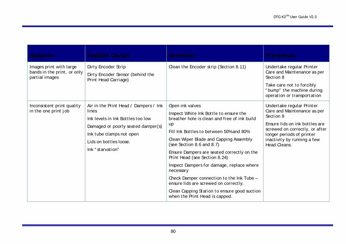
DTG K3TM User Guide V2.0
80
Symptom Possible Causes Remedies Prevention
Images print with large bands in the print, or only partial images
Dirty Encoder Strip
Dirty Encoder Sensor (behind the Print Head Carriage)
Clean the Encoder strip (Section 8.11)
Undertake regular Printer Care and Maintenance as per Section 8
Take care not to forcibly “bump” the machine during operation or transportation
Inconsistent print quality in the one print job
Air in the Print Head / Dampers / Ink lines
Ink levels in Ink Bottles too low
Damaged or poorly seated damper(s)
Ink tube clamps not open
Lids on bottles loose.
Ink “starvation”
Open ink valves
Inspect White Ink Bottle to ensure the breather hole is clean and free of ink build up
Fill Ink Bottles to between 50% and 80%
Clean Wiper Blade and Capping Assembly (see Section 8.6 and 8.7)
Ensure Dampers are seated correctly on the Print Head (see Section 8.24)
Inspect Dampers for damage, replace where necessary
Check Damper connection to the Ink Tube – ensure lids are screwed on correctly.
Clean Capping Station to ensure good suction when the Print Head is capped.
Undertake regular Printer Care and Maintenance as per Section 8
Ensure lids on ink bottles are screwed on correctly, or after longer periods of printer inactivity by running a few Head Cleans.
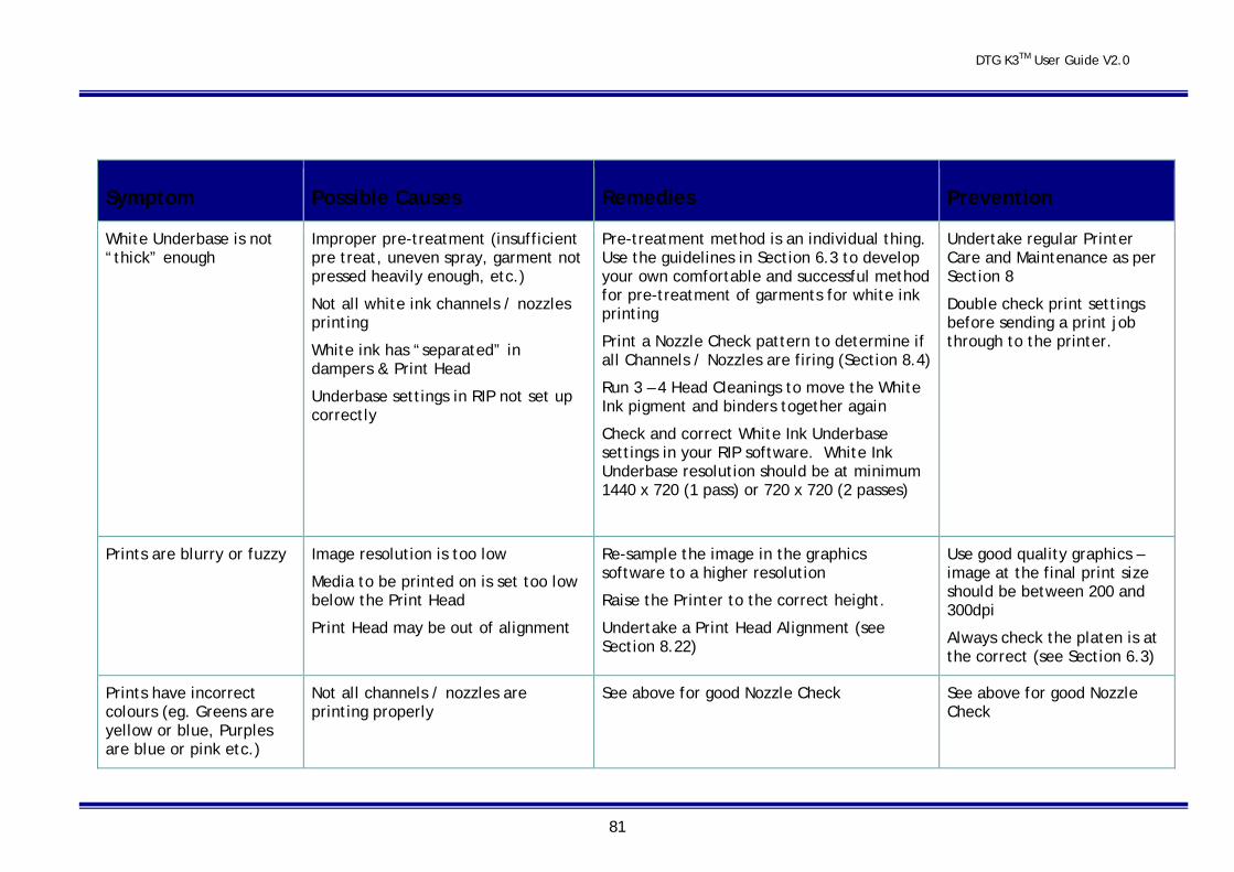
DTG K3TM User Guide V2.0
81
Symptom Possible Causes Remedies Prevention
White Underbase is not “thick” enough
Improper pre-treatment (insufficient pre treat, uneven spray, garment not pressed heavily enough, etc.)
Not all white ink channels / nozzles printing
White ink has “separated” in dampers & Print Head
Underbase settings in RIP not set up correctly
Pre-treatment method is an individual thing. Use the guidelines in Section 6.3 to develop your own comfortable and successful method for pre-treatment of garments for white ink printing
Print a Nozzle Check pattern to determine if all Channels / Nozzles are firing (Section 8.4)
Run 3 – 4 Head Cleanings to move the White Ink pigment and binders together again
Check and correct White Ink Underbase settings in your RIP software. White Ink Underbase resolution should be at minimum 1440 x 720 (1 pass) or 720 x 720 (2 passes)
Undertake regular Printer Care and Maintenance as per Section 8
Double check print settings before sending a print job through to the printer.
Prints are blurry or fuzzy Image resolution is too low
Media to be printed on is set too low below the Print Head
Print Head may be out of alignment
Re-sample the image in the graphics software to a higher resolution
Raise the Printer to the correct height.
Undertake a Print Head Alignment (see Section 8.22)
Use good quality graphics – image at the final print size should be between 200 and 300dpi
Always check the platen is at the correct (see Section 6.3)
Prints have incorrect colours (eg. Greens are yellow or blue, Purples are blue or pink etc.)
Not all channels / nozzles are printing properly
See above for good Nozzle Check See above for good Nozzle Check
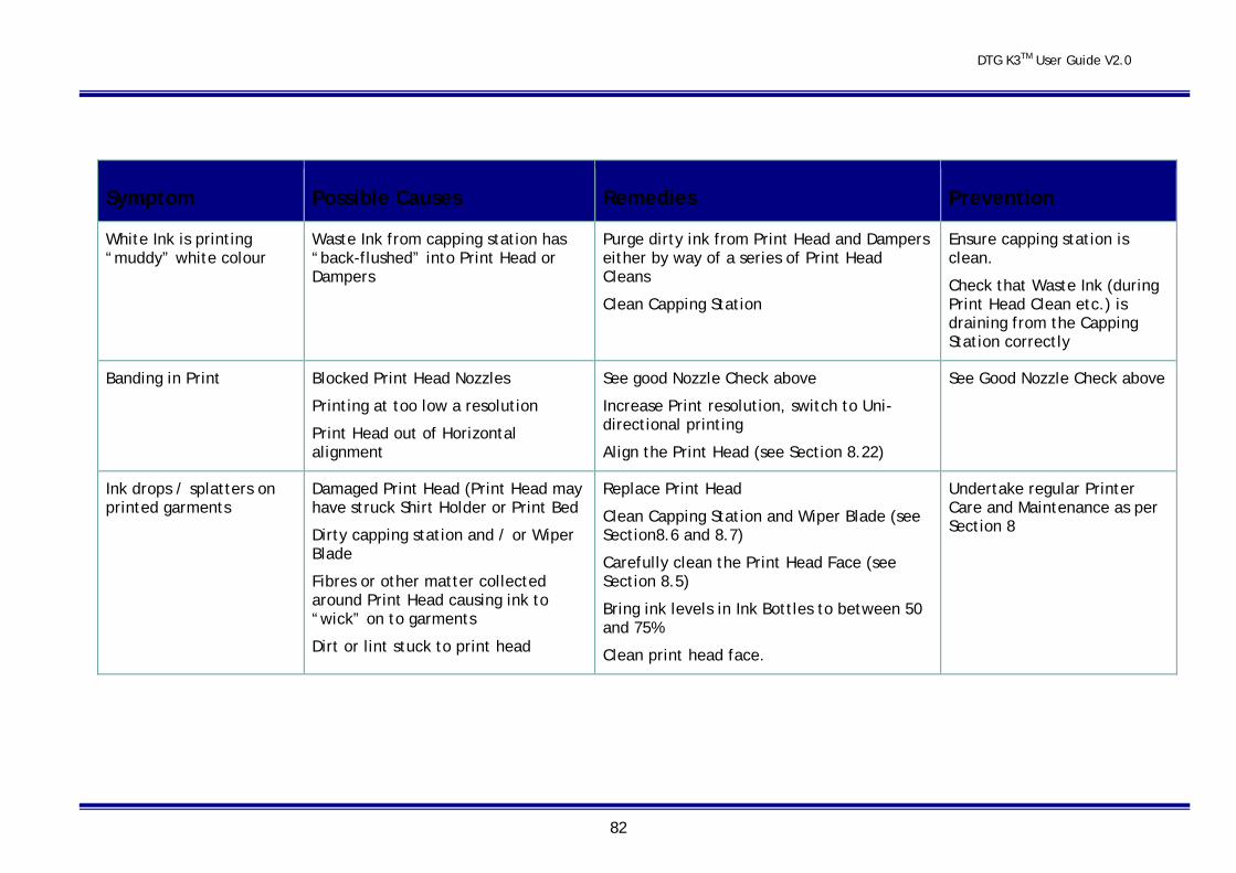
DTG K3TM User Guide V2.0
82
Symptom Possible Causes Remedies Prevention
White Ink is printing “muddy” white colour
Waste Ink from capping station has “back-flushed” into Print Head or Dampers
Purge dirty ink from Print Head and Dampers either by way of a series of Print Head Cleans
Clean Capping Station
Ensure capping station is clean.
Check that Waste Ink (during Print Head Clean etc.) is draining from the Capping Station correctly
Banding in Print Blocked Print Head Nozzles
Printing at too low a resolution
Print Head out of Horizontal alignment
See good Nozzle Check above
Increase Print resolution, switch to Uni-directional printing
Align the Print Head (see Section 8.22)
See Good Nozzle Check above
Ink drops / splatters on printed garments
Damaged Print Head (Print Head may have struck Shirt Holder or Print Bed
Dirty capping station and / or Wiper Blade
Fibres or other matter collected around Print Head causing ink to “wick” on to garments
Dirt or lint stuck to print head
Replace Print Head
Clean Capping Station and Wiper Blade (see Section8.6 and 8.7)
Carefully clean the Print Head Face (see Section 8.5)
Bring ink levels in Ink Bottles to between 50 and 75%
Clean print head face.
Undertake regular Printer Care and Maintenance as per Section 8
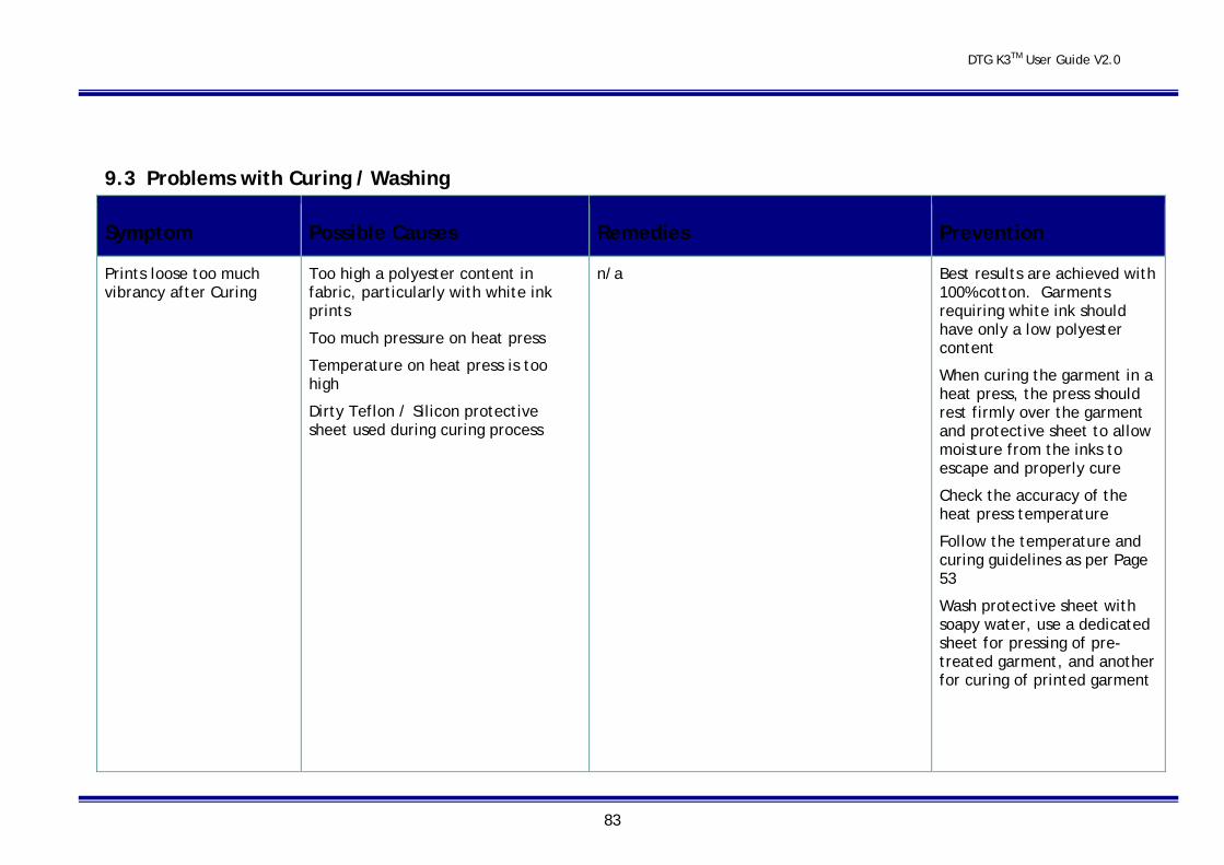
DTG K3TM User Guide V2.0
83
9.3 Problems with Curing / Washing
Symptom Possible Causes Remedies Prevention
Prints loose too much vibrancy after Curing
Too high a polyester content in fabric, particularly with white ink prints
Too much pressure on heat press
Temperature on heat press is too high
Dirty Teflon / Silicon protective sheet used during curing process
n/a Best results are achieved with 100% cotton. Garments requiring white ink should have only a low polyester content
When curing the garment in a heat press, the press should rest firmly over the garment and protective sheet to allow moisture from the inks to escape and properly cure
Check the accuracy of the heat press temperature
Follow the temperature and curing guidelines as per Page 53
Wash protective sheet with soapy water, use a dedicated sheet for pressing of pre-treated garment, and another for curing of printed garment
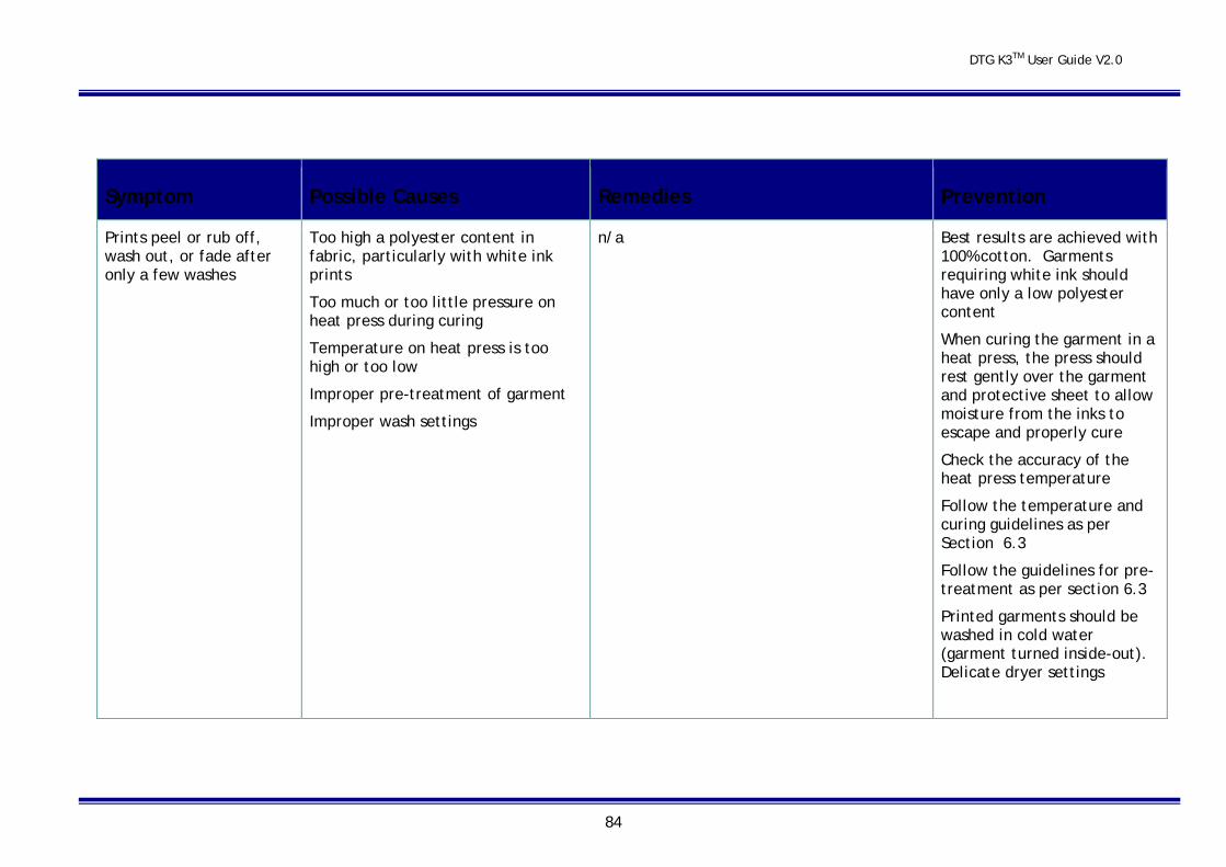
DTG K3TM User Guide V2.0
84
Symptom Possible Causes Remedies Prevention
Prints peel or rub off, wash out, or fade after only a few washes
Too high a polyester content in fabric, particularly with white ink prints
Too much or too little pressure on heat press during curing
Temperature on heat press is too high or too low
Improper pre-treatment of garment
Improper wash settings
n/a Best results are achieved with 100% cotton. Garments requiring white ink should have only a low polyester content
When curing the garment in a heat press, the press should rest gently over the garment and protective sheet to allow moisture from the inks to escape and properly cure
Check the accuracy of the heat press temperature
Follow the temperature and curing guidelines as per Section 6.3
Follow the guidelines for pre-treatment as per section 6.3
Printed garments should be washed in cold water (garment turned inside-out). Delicate dryer settings

DTG K3TM User Guide V2.0
85
10 Transporting or Storing Your Printer It is extremely important you observe the following before transporting or an extended shut down of your DTG K3™:
10.1 Preparing the printer for transportation / storage If the printer is to be transported over a long distance, and/or by a common carrier (where you cannot control the “care” with which the printer is transported) it is best to flush the printer of ink to avoid the possibility of ink spills and the ink drying in the print head.
Similarly, if the printer is not to be used for long periods of time, particulary where sample printing cannot be undertaken on a regular basis, it is best to flush the printer of ink to help diminish the risk of ink drying in the ink tubes / dampers / cartridges / Print Head.
Please contact your DTG Distributor / technician for full instructions on completely flushing your printer.
DTG K3TM User Guide V2.0
86
11 Product Support Our Support Policy We offer FREE support for the DTG K3™. Operating the unit is relatively easy, particularly if you follow the guidelines covered in this User Guide.
Support can be obtained by contacting the DTG Distributor from whom you purchased your DTG K3™. Support will generally be available during the Distributor’s normal business hours.
Before calling, please have your serial number at hand with specific details of the problem. If you have received an error message, please include the error number. You may find it easier to fax your questions before calling our support line.
Epson Support The DTG K3™ is NOT supported by Epson as it is a highly modified version of an Epson 1900 with hundreds of additional parts that are not provided by Epson. While we have approval from Epson to provide the Epson 1900 Printer Driver, Epson will not provide support for this driver. You must obtain any support for the Epson Driver and any internal Epson components you require from your DTG Distributor.
Third Party Software Support We will make every attempt to help with printing from programs like Corel Draw, Photoshop, Illustrator, etc., but we do not offer free support or training on these programs.

DTG K3TM User Guide V2.0
87
12 Requirements for PC Minimum System Requirements for Windows • Microsoft Windows compatible P4 PC with Windows XP home or professional recommended.
• A minimum of 1GB of RAM is recommended.
• A minimum of 200MB on your hard disk.
• A display monitor with a resolution of 1024 by 768 minimum.
• CD-ROM or DVD drives for installing the Printer Drivers.
• USB connection: 2 x USB 2.0 ports that comply with Windows.
Please Note: your RIP and graphics software will have additional system requirements. Please refer to your DTG Agent / Dealer for full specifications.
DTG K3TM User Guide V2.0
88
13 Printer Specifications
Method of printing: Piezo I.D.O.D Ink-Jet
Print Resolution: Max.1400×1440dpi
Max Printable Width: 300mm
Max Printable Length: 790mm
Max Print Media Thickness: 125mm (Max.thickness)
Ink: Five independent ink bottles Cyan, Magenta, Yellow, Black, White
Interface: USB 1 or 2
Power: 110-240V to suit local requirements
Power Consumption: Active: Approx 35W
Stay: Approx 25W
External Dimensions: Width: 470mm Length: 1260mm Height: 460mm
Weight: Approx 56KG
Included Printer Parts: USB Cable 1.8m
AC Power Cable 2m
CD with drivers and e-manual.

DTG K3TM User Guide V2.0
89
Limited Warranty Registration Card
Remove this page and copy and mail or fax within 10 days of receipt of machine to:
Impression Technology Pty Ltd
Unit 23 / 9 Powells Rd
Brookvale NSW 2100
Australia
Phone: +61 2 9905 0420
Fax: +61 2 9907 4744
Email: [email protected]
Company Name:_____________________________________________________
Contact Name:_______________________________________________________
Address:____________________________________________________________
City:__________________________________ State/Province:_______________
Zip/Postal Code:____________________ Country:_________________________
Phone:__________________________ Fax:_____________________________
Email:______________________________________________________________
Product: DTG K3™ Standard Serial Number:__________________________
Date Purchased:__________________ Date Received:_____________________
Purchased From:_____________________________________________________
Thank you for purchasing a DTG K3™!