User's 2768 Manual Precision Wheatstone Bridge276801 ― i ― Introduction Thank you for purchasing...
19
2768 Precision Wheatstone Bridge User's Manual IM 2768-01E IM 2768-01E 4th Edition: Oct. 2017 (YMI)
Transcript of User's 2768 Manual Precision Wheatstone Bridge276801 ― i ― Introduction Thank you for purchasing...

2768Precision Wheatstone Bridge
User'sManual
IM 2768-01E
IM 2768-01E4th Edition: Oct. 2017 (YMI)

IM 2768-01E
― i ―
IntroductionThank you for purchasing our Precision wheatstone bridge.
This manual describes the specifications and handling precautions of the Precision wheatstone bridge.
Before using this product, thoroughly read this manual to understand how to use it properly.
Contact information of Yokogawa offices worldwide is provided on the following sheet.
PIM 113-01Z2: Inquiries List of worldwide contacts
Notice regarding This User’s Manual
• The information covered in this User’s manual is subject to change without prior notice.
• Every effort has been made to ensure accuracy in the preparation of this manual.
Should any errors or omissions come to your attention however, please inform YOKOGAWA accordingly.
• YOKOGAWA is by no means liable for any damage resulting from the user’s mishandling of the product.
• This manual is intended to describe the functions of this product.
YOKOGAWA does not guarantee that these functions are suited to the particular purpose of the user.

IM 2768-01E
― ii ―
Cautionary Notes for Safe Use of the ProductWhen operating the instrument, be sure to observe the cautionary notes given below to ensure correct and
safe use of the instrument.
If you use the instrument in any way other than as instructed in this manual, the instrument’s protective
measures may be impaired.
This manual is an essential part of the product; keep it a safe place for future reference.
YOKOGAWA is by no means liable for any damage resulting from use of the instrument in contradiction to
these cautionary notes.
The following safety symbols are used on the instrument and in the manual:
Danger! Handle with Care.This mark indicates that operator must refer to an explanation inthe instruction manual in order to avoid risk of injury or death ofpersonnel or damage to the instrument.
This mark indicates earth (ground).
Since mishandling the instrument can result in an accident that may lead to injury or death of the operator, such as an electric shock, be sure to observe the following instructions.
WARNING
Protective Measures• If a crack appears in the instrument after it has been accidentally dropped or bumped,
the safety-purpose insulation may be damaged. By all means do not use the instrument, but ask the manufacture for repair.
Connection• To avoid electric shock, be sure to apply protective grounding to the grounding terminal.• Install a protection fuse as shown in the example of measurement.
Measurement• Always maintain the instrument within the limits for allowable current, voltage and power,
during operation. If there is more than one limit for any of these parameters, the lowest limit takes precedence.
External Power Supply• Only operate the instrument on a supply voltage no greater than 60 VDC.
Operating Environment• Do not operate the instrument in a flammable or explosive gas atmosphere.• Do not operate the instrument if there is any condensation on it.
Do Not Remove the Case or Disassemble• Do not open the case except when replacing batteries. Only Yokogawa service personnel are authorized to remove the casing or disassemble or
modify the instrument. Do not attempt to repair the instrument yourself, as doing so is extremely dangerous.

IM 2768-01E
― iii ―
Since mishandling the instrument can result in an accident, such as an electric shock, that may injure the operator or damage the instrument, be sure to observe the following instructions.
CAUTION
BatteriesDo not use a mixture of different types of batteries or a mixture of old and new batteries.If the instrument will not be used for a prolonged period, remove the batteries before storage.The battery fluid will leak more readily during long-term storage, resulting in instrument malfunction.
IM 2768-01E
― iv ―
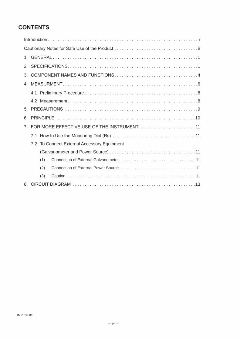
CONTENTS
Introduction . . . . . . . . . . . . . . . . . . . . . . . . . . . . . . . . . . . . . . . . . . . . . . . . . . . . . . . . . . . . . i
Cautionary Notes for Safe Use of the Product . . . . . . . . . . . . . . . . . . . . . . . . . . . . . . . . . . ii
1. GENERAL . . . . . . . . . . . . . . . . . . . . . . . . . . . . . . . . . . . . . . . . . . . . . . . . . . . . . . . . . . .1
2. SPECIFICATIONS. . . . . . . . . . . . . . . . . . . . . . . . . . . . . . . . . . . . . . . . . . . . . . . . . . . . .1
3. COMPONENT NAMES AND FUNCTIONS . . . . . . . . . . . . . . . . . . . . . . . . . . . . . . . . . .4
4. MEASURMENT. . . . . . . . . . . . . . . . . . . . . . . . . . . . . . . . . . . . . . . . . . . . . . . . . . . . . . .6
4.1 Preliminary Procedure . . . . . . . . . . . . . . . . . . . . . . . . . . . . . . . . . . . . . . . . . . . . . .6
4.2 Measurement . . . . . . . . . . . . . . . . . . . . . . . . . . . . . . . . . . . . . . . . . . . . . . . . . . . . .8
5. PRECAUTIONS . . . . . . . . . . . . . . . . . . . . . . . . . . . . . . . . . . . . . . . . . . . . . . . . . . . . . .9
6. PRINCIPLE . . . . . . . . . . . . . . . . . . . . . . . . . . . . . . . . . . . . . . . . . . . . . . . . . . . . . . . . .10
7. FOR MORE EFFECTIVE USE OF THE INSTRUMENT . . . . . . . . . . . . . . . . . . . . . . . 11
7.1 How to Use the Measuring Dial (Rs) . . . . . . . . . . . . . . . . . . . . . . . . . . . . . . . . . . 11
7.2 To Connect External Accessory Equipment
(Galvanometer and Power Source) . . . . . . . . . . . . . . . . . . . . . . . . . . . . . . . . . . . 11
(1) Connection of External Galvanometer. . . . . . . . . . . . . . . . . . . . . . . . . . . . . . . . . . 11
(2) Connection of External Power Source. . . . . . . . . . . . . . . . . . . . . . . . . . . . . . . . . . 11
(3) Caution. . . . . . . . . . . . . . . . . . . . . . . . . . . . . . . . . . . . . . . . . . . . . . . . . . . . . . . . . . 11
8. CIRCUIT DIAGRAM . . . . . . . . . . . . . . . . . . . . . . . . . . . . . . . . . . . . . . . . . . . . . . . . . .13

IM 2768-01E
― 1 ―
1. GENERAL
Precision Wheatstone Bridge 2768 is an instrument designed for measuring DC resistance from 0.1 Ω to 110 MΩ.This instrument is equipped with a galvanometer and a power source internally, and the measured value is indicated in-line indication without using any additional equipment externally.Moreover, this instrument is designed with maximum care for the precision and stability of resistance elements and also for the insulation of the measuring circuit, and is provided with a guard terminal and a ground terminal.Therefore the precision measurement is accomplished with 2768.
2. SPECIFICATIONS
× 100 mΩ
× 1 Ω
× 10 Ω
× 100 Ω
× 1 kΩ
× 10 kΩ
× 100 kΩ
× 1 MΩ
× 10 MΩ
10 µΩ
100 µΩ
1 mΩ
10 mΩ
100 mΩ
1 Ω
10 Ω
100 Ω
1 kΩ
±0.5 mΩ
±(0.02% of setting + 0.5 mΩ)
±0.02% of setting
±0.01% of setting
±0.01% of setting
±0.01% of setting
±0.02% of setting
±0.02% of setting
±0.05% of setting
0.10000 to 1.11110 Ω
1.1111 to 11.1110 Ω
11.111 to 111.110 Ω
0.11111 to 1.11110 kΩ
1.1111 to 11.1110 kΩ
11.111 to 111.110 kΩ
0.11111 to 1.11110 MΩ
1.1111 to 11.1110 MΩ
11.111 to 111.110 MΩ
Accuracy: at 23 ± 5°C, less than 75%
Measuring Range and Accuracy:
Range Measuring Range Accuracy Resolution

IM 2768-01E
― 2 ―
No. 1 Dial
No. 2 Dial
No.3 Dial
No. 4 Dial
No. 5 Dial
±0.006% (not included residual resistance.)
±0.01% (not included residual resistance.)
±0.1% (not included residual resistance.)
±0.5% (not included residual resistance.)
±5% (included residual resistance.)
1000 Ω × 10
100 Ω × 10
10 Ω × 10
1 Ω × 10
0.1 Ω × 10
At an ambient temperature of 23 ± 2°C, humidity of less than 75% R. H.
Residual resistance; Less than 0.02 Ω
(% of setting)
Measuring Arm:
Resistance Accuracy
× 100 mΩ
× 1 Ω
× 10 Ω
× 100 Ω
× 1 kΩ
× 10 kΩ
× 100 kΩ
× 1 MΩ
× 10 MΩ
±0.02%
±0.02%
±0.01%
±0.005%
±0.005%
±0.005%
±0.01%
±0.01%
±0.01%
10 Ω / 100 kΩ
10 Ω / 10 kΩ
100 Ω / 10 kΩ
1 kΩ / 10 kΩ
1 kΩ / 1 kΩ
10 kΩ / 1 kΩ
100 kΩ / 1 kΩ
100 kΩ / 100 Ω
100 kΩ / 10 Ω
*: At an ambient temperature of 23 ± 2°C, humidity of 75% R. H. and resistance ratio.
Ratio Arm; 0.2 W continuous
Measuring Arm; 0.2 W / Element, continuous
Ratio Arm:
Maximum Allowable Input:
Range Resistance Ratio Accuracy*

IM 2768-01E
― 3 ―
operative for approx. 300 hours.
(Dry Cell UM-1, or SUM-1 4 each and 006P 1 each)
at ambient humidity of less than 75%
(not including a handle and mounts)
Between the case and the circuits; More than 1000 MΩ at 250 VDC
User's Manual 1 each
Battery 1 set
Between the case and the circuits; 500 VAC, 1 minute
Maximum Sensitivity: Approximately 10µV / div.
Input Resistance: 9 kΩ
Max. Allowable Input Voltage: 5 V (peak value)
Power Source: 9 V (Dry Cell 006P) installed,
Galvanometer
Insulation Resistance:
Accessories:
Dielectric Strength:
Dimensions: Approx. 310 × 491 × 140 mm
Weight: Approx. 9.6 kg
Power Source: 1.5 V / 3 V / 6 V / 15 V

IM 2768-01E
― 4 ―
3. COMPONENT NAMES AND FUNCTIONS
[1]
[5]
[12] [11] [3] [4] [10] [13] [2]
[6] [7] [9] [8] [14]
Fig. 3.1 Front Panel
Galvanometer
5. 3
EXTGA
− EXTBA +
EXT
1.5V3V 6V 15V
POWER SUPPLY RANGE
EXT GAL H
×100 Ω×10 Ω×1 Ω
×1 kΩ×10 kΩ
×10 MΩ×1 MΩ×100 kΩ
×100 mΩ
BCHECK
4 8 9
BA GARs
(kΩ)Rx
GUARD YOKOGAWA
WHEATSTONE BRIDGE2768
L H
OFF INT GA SENSITIVITY
GUARD
(Front Panel)
[1] Measuring Arm:(Rs)
Is composed of 5 dial type variable resistors, and is able to change the resistance from 0.1 Ω till 11.111 kΩ in step of 0.1 Ω.The resistance value indicated in the windows is connected to the bridge circuit.
[2] Ratio Arm:(Range)
Used to select a multiplying factor depending on the resistance under test.
[3] Galvanometer Function SwitchINT. GA: Internal galvanometer is connected to the bridge circuit.
B CHECK: Used to check the power source for the internal galvanometer.(If the pointer reaches to the blue zone, the batteries are normal.)
EXT. GA: Internal galvanometer is connected to the bridge circuit.In this case, the power source for the galvanometer is set to OFF.

IM 2768-01E
― 5 ―
[4] Sensitivity Knob: Used to adjust the sensitivity of the internal galvanometer.Turn the knob to increase the sensitivity.
[5] Power Supply Function Switch:OFF: Power sources for the bridge circuit and the internal
galvanometer are switched off.
1.5 V to 15 V: Used to set the power supply voltage for the bridge circuit.The power source for the internal galvanometer will be ON.
EXT: The external power source is connected to the bridge circuit, and the power source for the internal galvanometer is set to ON.
[6] BA: This is a push button type switch used to switch the power source for the bridge circuit ON and OFF during measurement.
[7] GA: This is a push button type switch used to connect the galvanometer input to the bridge circuit.
[8] Rx Terminal: Used to connect the resistance under test.
[9] Rs Terminal: Used when the measuring dial (Rs) is employed as a variable resistor.
[10] EXT. GA Terminal: Used to connect the external galvanometer.
[11] EXT. BA Terminal: Used to connect the external power source.
[12] Ground Terminal
[13] Galvanometer Guard Terminal
[14] Rx Guard terminal
Battery Case: The case is located on the bottom of this instrument.Remove the cover by removing the screws to replace the batteries.The power source for the galvanometer is the dry cell battery (006P) located at the end of the case.

IM 2768-01E
― 6 ―
4. MEASURMENT
4.1 Preliminary Procedure
(1) Check of Galvanometer
Set the POWER SUPPLY function switch to ON, and the push button type switches BA and GA to OFF.Then position the galvanometer function switch at B CHECK.Next, set the galvanometer function switch to INT. GA to check if the pointer indicates 0 on the scale.If the pointer is deflected from the zero on the scale, turn the zero adjustment screw to shift the pointer to the zero on the scale.
(2) Connection of Resistor under Test (Rx)
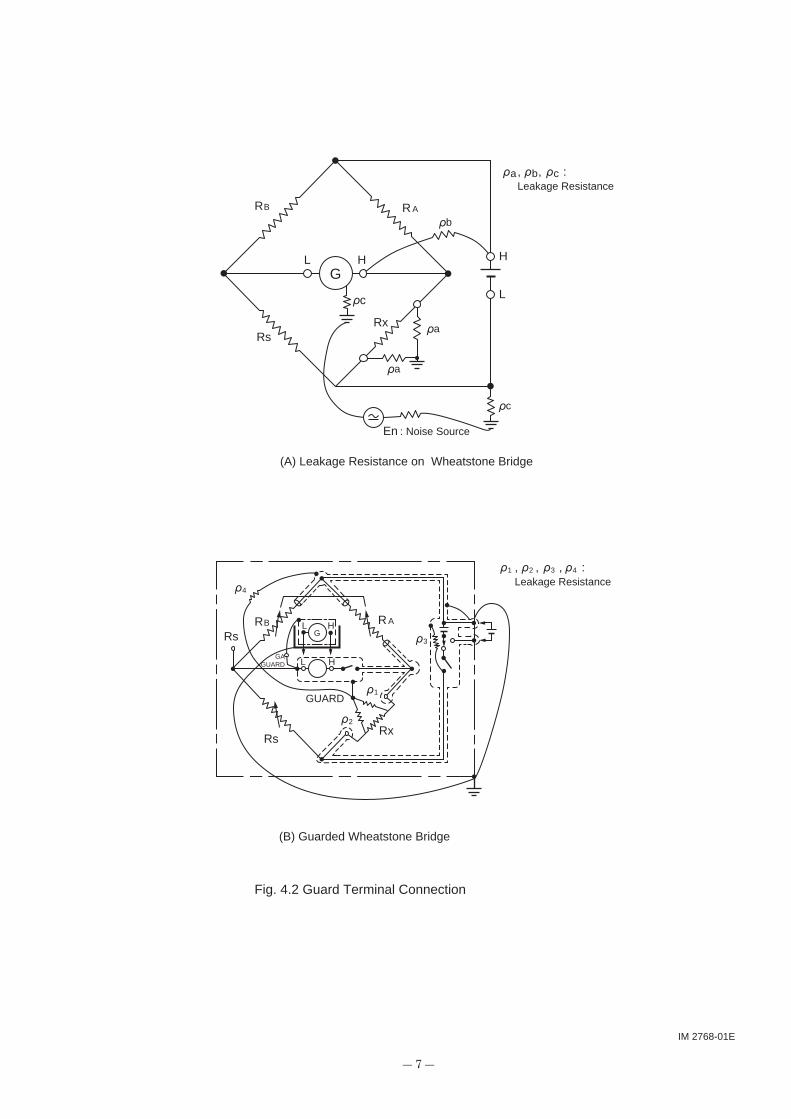
Connect the resistor to be measured to Rx terminals.A guard (3 terminal measurement) is required to measure a resistor higher than 100 kΩ accurately. (Fig. 4.1 and Fig. 4.2)
Rx
RxRx
ρ1 ρ2
to Rx terminals to Rx terminals Conductor
to GUARD terminal
to GUARD terminal
GUARD
Fig. 4.1 Rx and GUARD terminal Connection
(3) Selection of Multiplying Factor (Range)
Select the multiplying factor judging from the estimated value of the resistor under test connected to the Rx terminal.(Refer to the table listed in paragraph 2.)
IM 2768-01E
― 7 ―
G
GHHL
L
Rs
Rs
GUARD
GAGUARD
L
L
H
H
RsRx
ρa
ρa
ρc
ρc
ρbR A
R A
RB
RB
En
Rx
ρ4
ρ3
ρ1
ρ1 ρ2 ρ3 ρ4
ρ2
Fig. 4.2 Guard Terminal Connection
(B) Guarded Wheatstone Bridge
(A) Leakage Resistance on Wheatstone Bridge
, , , :Leakage Resistance
ρa ρb ρc, , :Leakage Resistance
: Noise Source

IM 2768-01E
― 8 ―
(4) Power Source Voltage and Null Balance Sensitivity
Select the power source voltage of the bridge circuit depending upon the resistor to be measured, and set the POWER SUPPLY function switch.3 V for the resistor under test which resistance is lower than 100 kΩ, and 150 V for those higher than 100 kΩ are typical setting of the function switch.With this voltage, the null balance sensitivity (Resistance variation of Rs side required to deflect one division from the balanced condition on the galvanometer) of this instrument is shown in Fig. 4.3.
0.1 Ω 1 Ω 1 MΩ 10 MΩ 100 MΩ1 kΩ 100 kΩ10 kΩ10 Ω 100 Ω
Fig. 4.3 Sensitivity and Accuracy
SensitivityAccuracy
0.001%
0.01%
0.1%
1%
10-5
10-4
10-3
10-2
10-1
/divRR
Rx
3 V 15 V
4.2 Measurement(1) Set the galvanometer to low sensitivity by turning the galvanometer SENSITIVITY
adjustment knob. (Turn the knob counter clockwise.)
(2) Set the measuring dials (Rs) to 1.9999.
(3) Observe the direction of the pointer deflection of the galvanometer by depressing momentarily the GA switch after depressing the BA switch.
If the pointer of the galvanometer deflects the plus ( ) side, increase the value of Rs dial, if the pointer is deflected to the minus ( ) side, decrease Rs to make the indication to 0.
When it reaches closely to an equilibrium, increase the sensitivity of the galvanometer and rebalance the bridge in the same manner as above.
When the galvanometer pointer indicates zero accurately, the value of unknown resistor can be obtained from the following:
Rx = (Dial Reading) × Multiplying factor (Ω)

IM 2768-01E
― 9 ―
5. PRECAUTIONS
(1) A measurement with high accuracy must be in a room where the temperature is stable to 18 to 25°C and where humidity is low.
After completion of the measurement, be sure to set the switches of POWER SUPPLY, GA and BA to OFF.
(2) In measurement, be sure to depress GA switch after BA switch has been depressed. If this order is reversed, the galvanometer pointer will misleadingly deflect for
the measuring dial operation inductance of the resistor under test when BA switch is depressed.
(3) The resistance of the lead wires which connect the resistance under test (Rx) to the Rx terminals, is included in the measured value.
Therefore, in measuring the resistance lower than 100 Ω, the influence of the lead wire resistance must be eliminated by measuring the resistor which is correctly calibrated, or by measuring the resistance of the lead wires.

IM 2768-01E
― 10 ―
6. PRINCIPLE
Fig. 6.1 is a theoretical diagram for a wheatstone bridge.
If the current flowing through the galvanometer is zero by adjusting Rs, the following relative equation is established.
Ix • R = Is • RA B
Ix • Rx = Is • Rs
AB
IsIx
RxRs
RR==
AB
RRRx = • Rs
This instrument is designed so that the multiplying factor is set from × 100 mΩ to × 10 MΩ by changing the RA / RB with the multiplying dial.Therefore, the unknown resistance Rx is obtained by multiplying the value of the measuring side dial Rs to the multiplying factor which is determined by the multiplying dial.
GA
Is
Ix
RxAR
BR
ig=0
Rs
Fig. 6.1 Theoretical diagram

IM 2768-01E
― 11 ―
7. FOR MORE EFFECTIVE USE OF THE INSTRUMENT
7.1 How to Use the Measuring Dial (Rs)The measuring dials (Rs) can be used as 5 dial variable resistors by separating them from the bridge circuit.The accuracy is 0.006% in maximum as shown in paragraph 2.It can be varied from 0.1 Ω to 11.1110 kΩ in 0.1 Ω step.Use Rs terminals and set POWER SUPPLY function switch to OFF to use this instrument as a variable resistor.
7.2 To Connect External Accessory Equipment (Galvanometer and Power Source)
When an external galvanometer which sensitivity is higher than the internal galvanometer, or any additional power sources are required for measurement, connect them as follows:
(1) Connection of External GalvanometerConnect the required galvanometer to EXT. GA terminals.Set the galvanometer function switch to EXT. GA.At the same time, the guard and the ground must be secured.Electronic Galvanometer 2709 is recommended to be used as an external galvanometer.(Maximum sensitivity 0.2 µA/div, input resistance 1 kΩ.) Note: Model 2709 has been discontinued.
(2) Connection of External Power SourceWhen a battery or a DC power source unit is required to be installed externally, connect it to EXT terminals and set POWER SUPPLY function switch to EXT. Ground side terminal of EXT. BA terminals.Accordingly connect the ground side of the external power source unit to side of this instrument.
(3) Caution(a) When internal batteries are not in use for long period,
remove the batteries from the instrument.
(b) In case a DC power source unit is used, if the ripple of the unit is large, the satisfactory operation of the galvanometer may not be expected due to the influence of the large ripple.

IM 2768-01E
― 12 ―
(c) When an external power source unit is used, be careful not to burn resistive elements by over-current.
The allowable electric power of this instrument is 0.2 W (continuous) which dose not degrade accuracy of the resistive element.
In case a power source unit is used of large capacity, connect a fuse 0.5 A in series with the power source.
(d) The maximum allowable input of the internal galvanometer is 5 V. When a high voltage external power source unit is used,
first roughly balance the galvanometer with a low voltage, and then increase the voltage. It is essential to complete the measurement as soon as possible. Be sure not set No. 1 dial of Rs to 0, and also not to short the Rx terminals.

IM 2768-01E
― 13 ―
8. CIRCUIT DIAGRAM
R20
0.5Ω
R19
0.2Ω
R18
0.2Ω
R17
0.1Ω
R26
90kΩ
R27
9kΩ
R28
900Ω
R29
90Ω
R30
10Ω
RV
10kΩ
R31
2.2M
Ω
R21
10Ω
R22
90Ω
R23
900Ω
R24
9kΩ
R25
90kΩ
S5
S6
S6
B6
S7
S8
G1
G1
S10
S6
to G
1
to G
1
R16
5ΩR15
2ΩR14
2ΩR13
1Ω
S4
S9
R4
5kΩ
R3
2kΩ
R2
2kΩ
R1
1kΩ
R33
330Ω
R34
10Ω
R32
10Ω
S1
G2
R8
500Ω
R7
200Ω
R6
200Ω
R5
100Ω
S2
S7
B5
006P
B4
B3
B2
B1
R12
50Ω
GU
AR
DE
XT.
R11
20Ω
R10
20Ω
R9
10Ω
S3
GA
LVA
B. C
HE
CK
INT.
GA
EX
T. G
A
GA
006P
GU
AR
D
GA
L (B
-)
BA
(B+)
From
RA
NG
E
RA
NG
E
× 10
0 mΩ
×
1 Ω
×
10 Ω
× 1
00 Ω
×
1 kΩ
× 1
0 kΩ
× 10
0 kΩ
×
1 MΩ
× 1
0 MΩ
M(±
5µA
)
AM
P
SE
NS
ITIV
ITY
L
L
H
H+M B
-
S21 -M S11
S12
EX
T.
PO
WE
R S
UP
PLY
BA
GU
AR
D
L
H
GU
AR
D
BA
T
BA
CA
SE
BA
CA
SE
UM
-1
15 V 6 V
3 V
1.5
V
OFF
EX
T.
53
48
9
Rx
Rs

Printed in Japan