User Operating-System Interface - Syl9.com - Main Page · · 2015-10-14Example of Windows and...
29
User Operating-System Interface Types of System Calls 5. Communication – (two common models) a) Message-passing model – communicating processes exchange messages with one another to transfer information. a) Shared-memory model - processes used shared memory create and shared memory attach system calls to create and gain access to regions of memory owned by other processes
Transcript of User Operating-System Interface - Syl9.com - Main Page · · 2015-10-14Example of Windows and...

User Operating-System Interface Types of System Calls
5. Communication – (two common models) a) Message-passing model – communicating processes exchange
messages with one another to transfer information.
a) Shared-memory model - processes used shared memory create and shared memory attach system calls to create and gain access to regions of memory owned by other processes

User Operating-System Interface Types of System Calls (Communication)
a) Message-passing model - Messages can be exchanged between processes
either directly or indirectly through a common mailbox
1. A connection must be opened
2. The name of other communicator must be known. Can be; 1. Another process on the same system
2. A process on another computer connected by a communications network (i.e. host name, ip address, process name), which is translated into an identifier in which the operating system refers to.
Both of the models are common in operating systems, and most systems implement both. Message passing is useful for exchanging smaller amounts of data, because no conflicts need be avoided. It is also easier to implement than is shared memory for intercomputer communication. Shared memory allows maximum speed and convenience of communication, since it can be done at memory transfer speed.

User Operating-System Interface Types of System Calls (Communication)
a) Shared-memory model – requires that two or more processes agree to remove
the restriction of preventing one process from accessing another process’s memory.
1. Information is exchanged by reading and writing data in shared areas.
2. The form of data is determined by the process (is not under the OS control)
3. Process are responsible for ensuring that they are not writing to the same memory location simultaneously
The get hostid and get processid system calls do this translation. The identifiers are then passed to the general-purpose open and close calls provided by the file system or to specific open connection and close connection system calls. The recipient process must usually give its permission for communication to take place with an accept connection call.

User Operating-System Interface Types of System Calls (Communication)
Summary of System calls
• Create, delete communication connection
• Send, receive messages
• Transfer status information
• Attach or detach remote devices.
Example of Windows and Unix System Calls
Windows Unix
Information Maintenance
CreatePipe() pipe()
CreateFileMapping() shmget()
MapViewOfFile() mmap()

User Operating-System Interface Types of System Calls
4. Protection – provides the mechanism for controlling access to the resources provided by a computer system
All computer systems, from servers to PDA’s, must be concerned with protection. Typically, system calls providing protection include set permission and get permission, which manipulate the permission settings of the resources such as files and disk. The allow user and deny user system calls specify whether particular users can – or cannot – be allowed access to certain resources.

User Operating-System Interface System Programs – also known as system utilities, provides a convenient environment for program development and execution. Some of them are simply interfaces to system calls; others are considerably more complex. These are the categories:
• File management – which are programs that create, delete, copy, rename, print, dump, list, and generally manipulates files and directories.
• Status information – the collecting of data pertaining to the system or process (i.e. system date, available memory, disk space, number of users, other status information, performance details, and logging, and debugging information.
• File modification (text editors) – the ability to create and modify the content of files stored on disk or other storage devices; may even include searches or transformation of text.

User Operating-System Interface • Programming-language support – Compilers, assemblers,
debuggers, and interpreters for common programming languages (such as C, C++, Java, Visual Basic, and PERL) are often provided to the user with the operating system.
• Program loading and execution – Once a program is assembled or compiled, it must be loaded into memory to be executed. The system may provide absolute loaders, relocatable loaders, linkage editors, and overlay loaders. Debugging systems for either high-level languages or machine languages are needed as well.
• Communications – These programs provide the mechanism for creating virtual connections among processes users, and computer systems. They allow users to send messages to one another’s screens, to browse Web pages, to send electronic-mail, to log in remotely, or to transfer file from one machine to another.

Operating-System Structure
• Simple Structure
Many commercial operating systems do not have well-defined structures. Frequently, such systems started as small, simple, and limited systems and then grew beyond their original scope. MS-DOS is an example of such a system. It was originally designed for a few people who had no idea that it would become so popular. It was written to provide the most functionality in the least space, so it was not divided into modules carefully.
Another example would be the original UNIX operating system. Like MS-DOS, UNIX initially was limit by hardware functionality.
It consist of two parts the kernel and the system programs.

Operating-System Structure
MS-DOS Layer Structure
application program
resident system program
MS-DOS device driver
ROM BIOS device driver
In MS-DOS, application programs are able to access the basic I/O routines to write directly to the display and disk drives. Such freedom leaves MS-DOS vulnerable to errant (or malicious) programs, causing entire system crashes when user programs fails.

Operating-System Structure • Layered Approach
With proper hardware support, operating systems can be broken into pieces that are smaller and more appropriate than those allowed by the original MS-DOS and UNIX systems.
A system can be made modular in many ways.
1. Layered Approach (levels) – where the bottom layer (layer 0) is hardware and the highest layer (layer N) is the user interface.
An operating-system layer is an implementation of an abstract object made up of data and the operations that can manipulate that data. A typical operating system layer – say, layer M – consists of data structures and a set of routines that can be invoked by higher-level layers. Layer M, in turn can invoke operations on lower-level layers.

Operating-System Structure
• Layered Approach
layer 0 hardware
layer 1
.
.
.
layer N user interface
Operating-System Structure
• Layered Approach
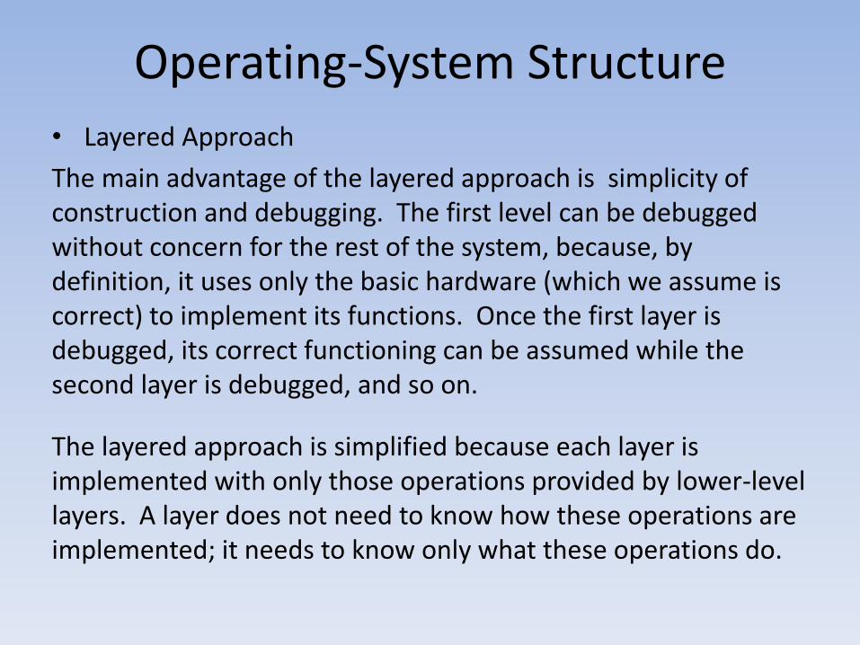
The main advantage of the layered approach is simplicity of construction and debugging. The first level can be debugged without concern for the rest of the system, because, by definition, it uses only the basic hardware (which we assume is correct) to implement its functions. Once the first layer is debugged, its correct functioning can be assumed while the second layer is debugged, and so on.
The layered approach is simplified because each layer is implemented with only those operations provided by lower-level layers. A layer does not need to know how these operations are implemented; it needs to know only what these operations do.

Operating-System Structure • Microkernels
Mach OS developed in mid-1980s at Carnegie Mellon University modularized the UNIX kernel using the microkernel approach.
This method structures the operating by removing all nonessential components from the kernel and implementing them as system and user-level programs, which results to a smaller kernel. It provides minimal process and memory management, in addition to a communication facility.
The main function of the microkernel is to provide a communication facility between the client program and the various services that are also running in user space, which provided by message passing.
Microkernels can suffer from performance decreases due to increased system functions (i.e. Window NT).

Operating-System Structure • Modules
Considered the best current methodology for operating-system design because it involves using object-oriented programming techniques to create a modular kernel.
The kernel has a set of core components and links in additional services either during boot time or during run time. This strategy uses dynamically loadable modules and is common in modern implementations of UNIX, such as Solaris, Linux, and Mac OS X.
This design allows the kernel to provide core services yet also allows certain features to be implemented dynamically. For example, device and bus drivers for specific hardware can be added to the kernel, and support for different file systems can be added as loadable modules.

Operating-System Structure • Solaris Loadable Modules
scheduling classes
device and bus drivers
miscellaneous modules
file systems
loadable system calls
STREAMS modules
executable formats
Core Solaris kernel

Operating-System Structure • Modules
The overall result resembles a layered system in that each kernel section has defined, protected interfaces; but it is more flexible than a layered system in that any module can call any other module. The approach is like the microkernel approach in that the primary module has only core functions and knowledge of how to load and communicate with other modules; but it is more efficient, because modules do not need to invoke message passing in order to communicate.

Chapter 3 - Processes • The Process
A process (job) is a program in execution. The process is more than the program code, which is sometimes know as the text section.
It also includes the current activity: 1. Program counter – the contents of the processor’s registers
2. Stack – contains temporary data (such as function parameters, return address, and local variables) and
3. Data section – contains global variables
4. Heap (may also be included) – memory that is dynamically allocated during process run time
Again, a program by itself is not a process; a program is a passive entity, such as a file containing a list of instructions stored on disk (often called an executable file) , where a process is an active entity, with a program counter specifying the next instruction to execute and a set of associated resources.

Chapter 3 - Processes • The Process
stack
data
text
heap
0
max
Process in memory.

Chapter 3 - Processes • Process State
As a process executes, it changes state. The state of a process is defined in part by the current activity of that process. Each process may be in one of the following states:
1. New – the process is being created.
2. Running – instructions are being executed.
3. Waiting – the process is waiting for some event to occur • I/O completion
• Reception of a signal
4. Ready – the process is waiting to be assigned to a processor.
5. Terminated – the process has finished execution.
The names of these states vary from operating system to operating system.

Chapter 3 - Processes • Process State

Chapter 3 - Processes • Process Control Block (PCB)
Each process is represented in the operating system by a process control block (PCB) – also called task control block. A PCB contains many pieces of information associated with a specific process, which includes:
1. Process state – (new, ready, running, waiting, halted, etc)
2. Program counter – indicates the address of the next instruction to be executed for this process.
3. CPU registers – includes accumulator, index registers, stack pointers, and general-purpose registers, plus any condition code information.
4. CPU-scheduling information – this information includes a process priority, pointers to scheduling queues, and any other scheduling parameters.
5. Memory-management information – this information includes the value of the base and limit registers, the page tables, or the segment tables, depending on the memory system used by the operating system.

Chapter 3 - Processes 6. Accounting Information – the amount of CPU and real time used,
time limits, account numbers, job or process numbers, etc.
7. I/O Status – the list of I/O devices allocated to the process, a list of open files, etc.
The PCB simply serves as the repository for any information that may vary from process to process.
Process Control Block (PCB)

Chapter 3 - Processes • Threads
The process model discussed thus far has implied that a process is a single thread of execution. For example, when a process is running a word-processing program, a single thread of instruction is being executed. This single thread of control allows the process to perform only one task at one time. The user cannot simultaneously type in characters and run the spell checker within the same process. A user cannot type in characters and run another word function (i.e. spell check) within the same process.
Some operating system allow processing multiple threads by extending the processing concept, enabling more than one task to be performed at one time.

Chapter 3 - Processes
CPU Switch from Process to Process
Chapter 3 - Processes Process Scheduling
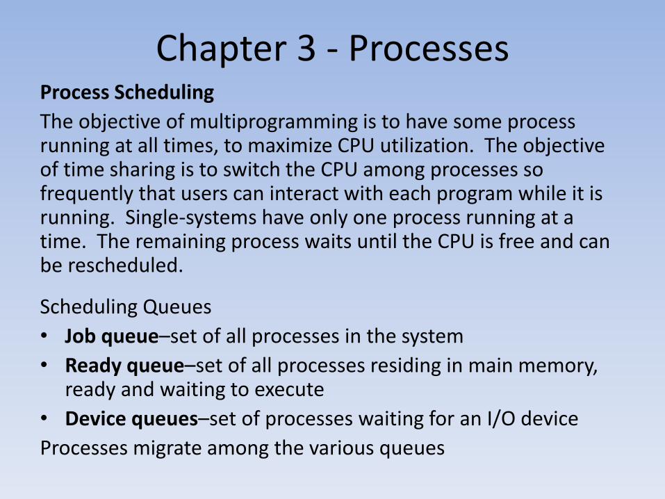
The objective of multiprogramming is to have some process running at all times, to maximize CPU utilization. The objective of time sharing is to switch the CPU among processes so frequently that users can interact with each program while it is running. Single-systems have only one process running at a time. The remaining process waits until the CPU is free and can be rescheduled.
Scheduling Queues
• Job queue–set of all processes in the system
• Ready queue–set of all processes residing in main memory, ready and waiting to execute
• Device queues–set of processes waiting for an I/O device
Processes migrate among the various queues

Chapter 3 - Processes When a process enters the system , it is placed in a job queue, which consist of all process in the system. Processes that resides in main memory and are ready and waiting to execute are kept on a list called the ready queue.
This queue is generally stored as a linked list. A ready-queue header contains pointers to the first and final PCBs in the list. Each PCB includes a pointer field that points to the next PCB in the ready queue.
There are other queues in the system, such as device queues. Suppose the process makes an I/O request to a shared device, such as a disk. The list of processes in the system, the disk may be busy with I/O request of some other process. The process therefore may have to wait for the disk. The list of process wainting for a particular I/O devices is called a device queue.

Chapter 3 - Processes
The Ready Queue and Various I/O Device Queues

Chapter 3 - Processes
Queueing-Diagram Representation of Process Scheduling

Chapter 3 - Processes A new process is initially put in the ready queue. It waits there until it is selected for execution. Or is dispatched. Once the process is allocated and is executed, one of several events could occur:
• The process could issue an I/O request and then be placed in an I/O queue.
• The process could create a new subprocess and wait for the subprocess’s termination
• The process could be removed forcibly from the CPU, as a result of an interrupt, and be put back in the ready queue.
In the first two cases, the process eventually switches from the waiting state and is then put back in the ready queue. A process continues this cycle until it terminates, at which time it is removed from all queues and has its PCB and resources deallocated.


![Awo Training Part 2 Prayer cycle[1] - Higher Intellect | … · · 2013-01-14example of the personal and collective chanting done in Ifa. This cycle has a wide range of variation](https://static.fdocuments.net/doc/165x107/5acd7dd77f8b9a875a8de02b/awo-training-part-2-prayer-cycle1-higher-intellect-of-the-personal-and.jpg)